


 Loading...
Smeg PGF95-3, PGF95BE3, PGF95SC3, PGF95F-4, PGF95K-4 User Manual
...Summary
1INSTRUCTIONS FOR SAFE AND PROPER USE_______________ 20
2POSITIONING OF THE HOB _______________________________ 22
3ADJUSTMENT TO DIFFERENT TYPES OF GAS _______________ 29
4FINAL OPERATIONS_____________________________________ 31
5USING THE HOB ________________________________________ 32
6CLEANING AND MAINTENANCE ___________________________ 34
THESE INSTRUCTIONS ARE VALID ONLY FOR END USER COUNTRIES WHOSE IDENTIFICATION SYMBOLS APPEAR ON THE COVER OF THIS MANUAL.
INSTRUCTIONS FOR THE INSTALLER: these are for the qualified technician who must carry out a suitable check of the gas system, install the appliance, set it functioning and carry out an inspection test.
INSTRUCTIONS FOR THE USER : these contain user advice, description of the commands and the correct procedures for cleaning and maintenance of the appliance.
19
Introduction
1 INSTRUCTIONS FOR SAFE AND PROPER USE
THIS MANUAL IS AN INTEGRAL PART OF THE APPLIANCE AND THEREFORE MUST BE KEPT IN ITS ENTIRETY AND IN AN ACCESSIBLE PLACE FOR THE WHOLE WORKING LIFE OF THE HOB. WE ADVISE READING THIS MANUAL AND ALL THE INSTRUCTIONS THEREIN BEFORE USING THE HOB. ALSO KEEP THE SERIES OF NOZZLES SUPPLIED. INSTALLATION MUST BE CARRIED OUT BY QUALIFIED PERSONNEL IN ACCORDANCE WITH THE REGULATIONS IN FORCE. THIS APPLIANCE IS INTENDED FOR FOR DOMESTIC USES AND CONFORMS TO EEC DIRECTIVES CURRENTLY IN FORCE. THE APPLIANCE IS DESIGNED TO CARRY OUT THE FOLLOWING FUNCTIONS: COOKING AND HEATING FOOD; ALL OTHER USES ARE TO BE CONSIDERED IMPROPER.
THE MANUFACTURER DECLINES ALL LIABILITY FOR IMPROPER USE .
DO NOT LEAVE THE PACKAGING MATERIALS UNATTENDED IN THE HOME ENVIRONMENT. SEPARATE THE DIFFERENT WASTE MATERIALS FROM THE PACKAGING AND DELIVER THEM TO THE NEAREST COLLECTION CENTRE FOR RECYCLABLE WASTE.
REGULATIONS REQUIRE THAT THE APPLIANCE IS EARTHED IN ACCORDANCE WITH ELECTRICAL SAFETY REGULATIONS.
THE PLUG TO BE CONNECTED TO THE POWER SUPPLY CABLE AND THE SOCKET MUST BE OF THE SAME TYPE AND MUST CONFORM TO CURRENT REGULATIONS.
THE POWER SOCKET MUST BE ACCESSIBLE AFTER THE APPLIANCE HAS BEEN BUILT IN.
NEVER UNPLUG THE APPLIANCE BY PULLING THE POWER SUPPLY CABLE.
IMMEDIATELY AFTER INSTALLATION, CARRY OUT A BRIEF INSPECTION TEST OF THE APPLIANCE, FOLLOWING THE INSTRUCTIONS BELOW. SHOULD THE APPLIANCE NOT FUNCTION, DISCONNECT IT FROM THE POWER SUPPLY AND CONTACT YOUR NEAREST TECHNICAL ASSISTANCE CENTRE.
NEVER ATTEMPT TO REPAIR THE APPLIANCE YOURSELF.
ALWAYS CHECK THAT THE CONTROL KNOBS ARE IN THE POSITION  (OFF) WHEN YOU FINISH USING THE HOB.
20

Introduction
THE APPLIANCE DATA PLATE, WITH TECHNICAL DATA, REGISTRATION NUMBER AND BRAND NAME, IS POSITIONED AT A VISIBLE POINT UNDER THE SAFETY COVER.
THE DATA PLATE ON THE PROTECTIVE COVER MUST NEVER BE REMOVED.
DO NOT PUT PANS WITHOUT PERFECTLY PERFECTLY SMOOTH AND FLAT BOTTOMS ON THE HOB PANSTAND GRIDS.
DO NOT USE COOKING RECEPTACLES THAT EXTEND BEYOND THE OUTSIDE PERIMETER OF THE HOB.
THE APPLIANCE IS DESIGNED FOR USE BY ADULTS. DO NOT ALLOW CHILDREN TO GO NEAR OR PLAY WITH IT.
THIS APPLIANCE IS MARKED ACCORDING TO THE EUROPEAN DIRECTIVE 2002/96/EC ON WASTE ELECTRICAL AND ELECTRONIC EQUIPMENT (WEEE).
THIS GUIDELINE IS THE FRAME OF A EUROPEAN-WIDE VALIDITY OF RETURN AND RECYCLING ON WASTE ELECTRICAL AND ELECTRONIC EQUIPMENT.
The manufacturer declines all liability for injury to persons or animals and for damage to property resulting from non-observance of the above prescriptions or from tampering with any part of the appliance or for the use of non-original spare parts.
21
Instructions for the installer
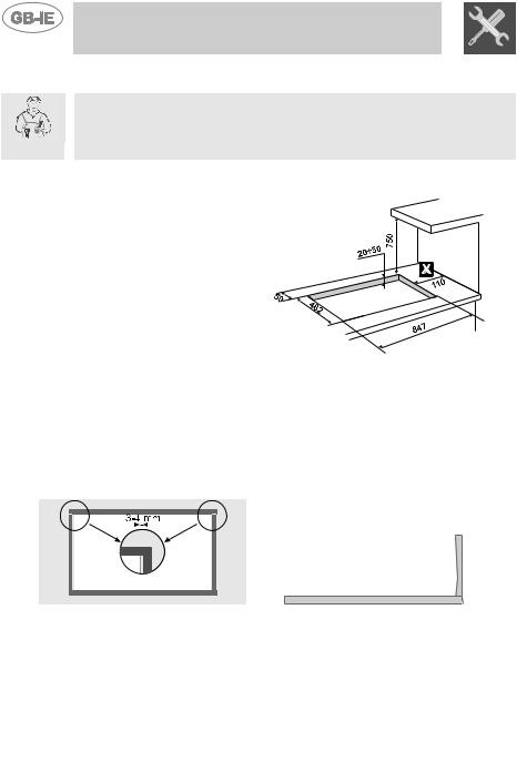
2 POSITIONING OF THE HOB
The following operation requires building and/or carpentry work so must be carried out by a competent tradesman.
Installation can be carried out on various materials such as masonry, metal, solid wood or plastic laminated wood, as long as they are heatresistant (T 90°C).
2.1Attachment to support structure, traditional built-in
model
Create an opening with the dimensions |
|
shown in the figure in the work surface, |
|
observing a minimum distance of 50 mm |
|
from the rear edge. |
|
This appliance can be installed next to walls |
|
that are higher than the work surface, as |
|
long as the distance "X" is kept between the |
|
appliance and the wall, as shown in the |
|
figure, to avoid damage from overheating. |
1) |
Make sure there is a minimum of 750 |
mm between the gas rings and any shelf that may be installed directly above them. Carefully position the gasket provided all around the outer edge of the hole in the work surface as shown in figure 2, pressing it down lightly to ensure it adheres properly. The front and rear sides of the gasket must skim the hole. Now place the hob on the insulating gasket and use the screws and fixing brackets (fig. 4) to secure the hob to the supporting structure, adjusting it until perfectly horizontal.
Carefully trim off the excess edge of the gasket C (Fig.3). The dimensions in figure 2 below refer to the distance between the hole and the inside edge of the gasket. Do not fit the brackets shown in fig. 4 until the hob has been set in place.
2) |
|
|
|
|
|
|
|
3) |
|
|
|
|
|
|
|
||
|
|
|
|
|
|
|
||
|
|
|
|
|
|
|
||
|
|
|
|
|
|
|
||
|
|
|
|
|
|
|
||
|
|
|
|
|
|
|
4)
22

Instructions for the installer
2.2Attachment to support structure, flush-mounting model
Create an opening with the dimensions |
|
|
shown in the figure in the work surface, |
|
|
observing a minimum distance of 50 mm |
|
|
from the rear edge. |
|
|
The lower part of the protective cover |
|
|
must be fully accessible when the |
|
|
appliance is installed. This appliance can |
|
|
be installed next to walls that are higher |
|
|
than the work surface, as long as the |
|
|
distance "X" is kept, as shown in the |
1) |
|
figure, to avoid damage from overheating. |
||
|
Make sure there is a minimum of 750 mm (Fig. 1) between the gas rings and any shelf that may be installed directly above them. This type of appliance also requires a cut 3 mm deep in the work-top with the dimensions shown in figure 4 (detail A, figure 2).
Before positioning the hob, position the adhesive sponge material “E” supplied over the milled surface (fig. 2). Now place the hob on the cut in the work-top and use the screws and fixing brackets (sequence shown in Fig. 3) to secure the hob to the supporting structure, adjusting it until perfectly horizontal. Do not fit the brackets shown in fig. 3 until the hob has been set in place.
3)
2)
3
4)
A
Apply a layer of “waterproof primer” to the milled surface.
23

Instructions for the installer
Important: Other types of installation will only be possible under the manufacturer's supervision.
Overall dimensions: location of gas and electrical connection points (all measures in mm).
Caution: surface temperature underneath may exceed 125 degrees C. To avoid a hazard, under-bench access must be restricted.
Refer to installation instruction
24
Loading...