

qbkbl
lйЙк~нбеЦ=fелнкмЕнбзел=
bеЦдблЬ


Sirona Dental Systems GmbH
Operating Instructions TENEO Table of contents
Table of contents
1 General information ................................................................................... 9
1.1 Dear Customer, ................................................................................ 9
1.2 Contact data ..................................................................................... 9
1.3 Notes on these Operating Instructions ............................................. 9
1.4 Other valid documents ..................................................................... 10
1.5 Warranty and liability ........................................................................ 10
1.6 Intended use ..................................................................................... 11
1.7 Formats and symbols used .............................................................. 11
2 Safety information...................................................................................... 12
2.1 Identification of danger levels ........................................................... 12
2.2 Information on the unit ...................................................................... 12
2.3 On-site installation ............................................................................ 12
2.4 Media quality .................................................................................... 12
2.5 Maintenance and repair .................................................................... 13
2.6 Trouble-free operation ...................................................................... 13
2.7 Vacuum system ................................................................................ 13
2.8 Patient chair ..................................................................................... 14
2.9 Ventilation slots ................................................................................ 14
2.10 Intermittent operation ....................................................................... 14
2.11 Touchscreen ..................................................................................... 14
2.12 Care and cleaning agents ................................................................ 14
2.13 Modifications and extensions of the system ..................................... 15
2.14 Electromagnetic compatibility ........................................................... 15
2.15 HF surgery ........................................................................................ 15
2.16 Dismantling/Installation .................................................................... 16
3 System description .................................................................................... 17
3.1 Standards/Approvals ........................................................................ 17
3.2 System overview .............................................................................. 18
3.3 Patient chair ..................................................................................... 19
3.4 Headrest ........................................................................................... 19
3.4.1 Motor-driven headrest .......................................................... 19
3.4.2 MultiMotion headrest............................................................ 20
3.5 Foot control ...................................................................................... 21
61 93 556 D3509
D3509.201.01.02.02 19.09.2008
3

Sirona Dental Systems GmbH
Table of contents Operating Instructions TENEO
3.6 Dentist element ................................................................................ 22
3.6.1 Instrument positions ............................................................. 23
3.6.2 EasyTouch user interface .................................................... 23
3.6.3 Touchscreen ........................................................................ 24
3.6.4 Fixed keys on the dentist element........................................ 25
3.7 Assistant element ............................................................................. 27
3.7.1 Instrument positions ............................................................. 28
3.7.2 User interface....................................................................... 28
3.7.3 Fixed keys on the assistant element .................................... 28
3.8 Water unit ......................................................................................... 29
3.9 External device connection .............................................................. 30
4 Operation .................................................................................................... 32
4.1 Starting up the treatment center ....................................................... 32
4.1.1 Initial startup......................................................................... 32
4.1.2 Switching the treatment center on/off................................... 32
4.1.3 Selecting a user profile......................................................... 33
4.2 Control concept of touchscreen ....................................................... 34
4.3 Foot control ...................................................................................... 35
4.3.1 Wireless foot control............................................................. 35
4.3.2 Operating the foot control..................................................... 36
4.3.3 Using the cursor control ....................................................... 38
4.4 Patient chair ..................................................................................... 40
4.4.1 Safety information ................................................................ 40
4.4.2 Safety stop ........................................................................... 41
4.4.3 Triggering an immediate movement stop............................. 42
4.4.4 Armrests............................................................................... 43
4.4.5 Simple/Advanced Start program operating mode ................ 44
4.4.6 Adjusting the motor-driven headrest .................................... 46
4.4.7 Adjusting the MultiMotion headrest ...................................... 47
4.4.8 Moving the patient chair via chair programs ........................ 49
4.4.9 Moving the chair manually ................................................... 52
4.4.10 Creating chair and shock positioning programs ................... 55
4.4.11 Setting the Massage/Active lumbar support functions ......... 55
4 D3509.201.01.02.02 19.09.2008
61 93 556 D3509

Sirona Dental Systems GmbH
Operating Instructions TENEO Table of contents
4.5 Dentist element ................................................................................ 56
4.5.1 Maximum load capacity........................................................ 56
4.5.2 Height adjustment ................................................................ 56
4.5.3 Motor-driven travel track....................................................... 56
4.5.4 Fixed keys on the dentist element........................................ 57
4.5.5 Quick setting keys and function levels ................................. 62
4.5.6 Saving instrument settings ................................................... 63
4.5.7 Placing the instruments in their holders ............................... 64
4.5.8 General instrument functions ............................................... 64
4.5.9 Electric motor ....................................................................... 69
4.5.10 Turbine ................................................................................. 73
4.5.11 SPRAYVIT L multifunctional syringe.................................... 73
4.5.12 SIROSONIC TL scaler ......................................................... 76
4.5.13 SIROTOM HF electrosurgical handpiece............................. 78
4.5.14 Implantological and endodontic treatments.......................... 84
4.6 Assistant element ............................................................................. 100
4.6.1 Maximum load capacity........................................................ 100
4.6.2 Height adjustment ................................................................ 100
4.6.3 Positionability ....................................................................... 100
4.6.4 Fixed keys on the assistant element .................................... 100
4.6.5 Suction handpieces.............................................................. 102
4.6.6 SPRAYVIT L multifunctional syringe .................................... 103
4.6.7 Mini L.E.D. curing light ......................................................... 104
4.6.8 Hydrocolloid.......................................................................... 107
4.7 Water unit ......................................................................................... 109
4.7.1 Swiveling the cuspidor bowl ................................................. 109
4.7.2 Tumbler filling with automatic sensor control ....................... 109
4.7.3 Adjusting the water amount for flushing ............................... 110
4.8 Tray .................................................................................................. 111
4.9 X-ray viewer ..................................................................................... 111
4.9.1 Attachment versions............................................................. 111
4.9.2 Switching the X-ray viewer on/off ......................................... 112
4.9.3 Attaching the anti-glare film.................................................. 112
4.10 SIROLUX FANTASTIC operating light ............................................. 113
4.10.1 Switching the operating light on/off and adjusting it ............. 113
4.10.2 Switching the composite function on/off............................... 113
4.11 SIVISION digital video system ......................................................... 114
4.11.1 SIVISION monitor................................................................. 114
4.11.2 SiroCam digital intraoral camera.......................................... 115
61 93 556 D3509
D3509.201.01.02.02 19.09.2008
5

Sirona Dental Systems GmbH
Table of contents Operating Instructions TENEO
4.12 External PC ...................................................................................... 119
4.12.1 SIVISION program ............................................................... 119
4.12.2 Open USB port..................................................................... 123
4.13 Configuration of the treatment center (setup) .................................. 123
4.13.1 Opening the setup programs................................................ 123
4.13.2 Configuring the EasyTouch user interface ........................... 124
4.13.3 Setting the date and time ..................................................... 125
4.13.4 Configuring control options .................................................. 126
4.13.5 Configure instruments .......................................................... 129
4.13.6 Configuring the network connection..................................... 131
4.13.7 Opening the Service domain................................................ 133
5 Care and cleaning instructions for the practice team ............................ 134
5.1 Basics ............................................................................................... 134
5.1.1 Intervals................................................................................ 134
5.1.2 Care and cleaning agents .................................................... 135
5.1.3 Microbiological water test..................................................... 135
5.2 Surfaces ........................................................................................... 136
5.2.1 Cleaning/disinfecting surfaces ............................................. 136
5.2.2 Disinfect the EasyTouch ...................................................... 137
5.2.3 Disinfecting handles ............................................................. 137
5.2.4 Disinfecting the tray.............................................................. 138
5.2.5 Disinfect, clean and care for the upholstery ......................... 139
5.2.6 Disinfecting the MultiMotion headrest .................................. 139
5.2.7 Thermally disinfect the instrument holder of the dentist element
140
5.2.8 Thermally disinfect the instrument holder of the assistant element
141
5.2.9 Clean the foot control ........................................................... 141
5.3 Instruments and instrument hoses ................................................... 141
5.3.1 Rinsing water lines ............................................................... 141
5.3.2 Purge water lines (purge function) ....................................... 142
5.3.3 Automatically purge water lines (autopurge function) .......... 144
5.3.4 Care for, disinfect and sterilize the treatment instruments... 148
5.3.5 Changing the cotton wool roll on the turbine hose............... 150
5.4 Vacuum system ................................................................................ 150
5.4.1 Purge the vacuum system.................................................... 150
5.4.2 Sterilize and disinfect the suction handpieces ..................... 150
5.4.3 Cleaning and disinfecting the vacuum system..................... 151
5.4.4 Cleaning and disinfecting the suction hoses........................ 153
5.4.5 Thermodisinfecting suction hoses........................................ 154
6 D3509.201.01.02.02 19.09.2008
61 93 556 D3509

Sirona Dental Systems GmbH
Operating Instructions TENEO Table of contents
5.5 Components of the water unit .......................................................... 155
5.5.1 Clean the gold trap............................................................... 155
5.5.2 Clean and disinfect the cuspidor bowl.................................. 155
5.5.3 Adding disinfectant for water................................................ 156
5.5.4 Change the water and air filters ........................................... 157
5.5.5 Changing the amalgam rotor................................................ 157
5.5.6 Emptying the sediment container ......................................... 159
5.5.7 Cleaning the filter insert of the wet suction device ............... 160
5.6 Sanitize the treatment center ........................................................... 162
5.7 Foot control and connection box ...................................................... 168
5.7.1 Changing the battery of the wireless foot control ................. 168
5.7.2 Changing the fuse of the external device connection........... 169
6 Maintenance by the service engineer....................................................... 170
6.1 Inspection and maintenance ............................................................ 170
6.2 Safety checks ................................................................................... 170
6.3 Safety tests for systems with HF surgical equipment ....................... 171
6.4 Maintenance Manual ........................................................................ 171
7 Malfunctions ............................................................................................... 172
7.1 Error messages ................................................................................ 172
7.2 Remote maintenance ....................................................................... 173
8 Spare parts and consumables .................................................................. 174
9 Technical data............................................................................................. 176
10 Disposal....................................................................................................... 178
11 Overview of all function keys.................................................................... 179
11.1 Fixed keys ........................................................................................ 179
11.1.1 Dentist element .................................................................... 179
11.1.2 Assistant element................................................................. 180
11.2 Start program ................................................................................... 181
11.3 Instrument program .......................................................................... 182
11.4 Treatment program ........................................................................... 183
11.4.1 Treatment selection.............................................................. 183
11.4.2 Implantology......................................................................... 184
11.4.3 Endodontics.......................................................................... 185
11.4.4 Endodontics administration .................................................. 185
61 93 556 D3509
D3509.201.01.02.02 19.09.2008
7

Sirona Dental Systems GmbH
Table of contents Operating Instructions TENEO
11.5 Other dialogs .................................................................................... 186
11.5.1 Timer screen ........................................................................ 186
11.5.2 SPRAYVIT program ............................................................. 186
11.5.3 Tumbler filling settings screen.............................................. 186
11.5.4 Flushing settings screen ...................................................... 187
11.6 SIVISION program ........................................................................... 187
11.6.1 SIDEXIS ............................................................................... 187
11.6.2 PowerPoint........................................................................... 189
11.6.3 Media Player ........................................................................ 189
11.7 Setup program ................................................................................. 189
11.7.1 User interface....................................................................... 189
11.7.2 Date and time....................................................................... 190
11.7.3 Control options ..................................................................... 190
11.7.4 Instruments .......................................................................... 191
11.7.5 Network connection.............................................................. 192
11.7.6 Service domain .................................................................... 192
Index ............................................................................................................ 193
NOTE:
For quick navigation within this document, we have provided an index starting
from page 193.
8 D3509.201.01.02.02 19.09.2008
61 93 556 D3509

Sirona Dental Systems GmbH 1 General information
Operating Instructions TENEO Dear Customer,
1 General information
1.1 Dear Customer,
We are pleased that you have equipped your practice with the TENEO®
treatment center.
Our claim is to recognize our customers' demands in good time and to create
innovative solutions. Together with your trade partner, you have configured
the unit to suit your individual taste. The new hub of your treatment room is
tailored to your personal needs.
®
With TENEO
innovative comfort and high quality design. With TENEO® we have enhanced
proven functions and turned customer requirements into innovations. In
conjunction with the EasyTouch user interface, the reliable travel track
concept now makes treatment more pleasant and efficient than ever before.
These Operating Instructions are designed to assist you prior to initial use and
whenever you require information later on.
We wish you much success and pleasure with TENEO
Your TENEO
you have a treatment center that stands for easy operation,
®
.
®
Team
1.2 Contact data
Customer Service Center Our German and English speaking Product Service staff are ready to answer
your technical questions by telephone from 7:30 a.m. to 5:30 p.m. CET. Of
course, you can also contact us by fax or e-mail outside of these working
hours as well.
Phone: +49 (0) 6251/16-1616
Fax: +49 (0) 6251/16-1818
E-Mail: product.service@sirona.de
To speed up the processing of your letter, be sure to specify "Bereich
Behandlungseinheiten" (Treatment Center Division) in the subject line of your
e-mail or fax.
Manufacturer's address Sirona Dental Systems GmbH
Fabrikstrasse 31
64625 Bensheim
Germany
Phone: +49 (0) 6251/16-0
Fax: +49 (0) 6251/16-2591
E-Mail: contact@sirona.com
www.sirona.com
1.3 Notes on these Operating Instructions
Observe the Operating Instructions Please familiarize yourself with the unit by reading through these Operating
Instructions before putting it into operation. It is essential that you comply with
the specified warning and safety information.
61 93 556 D3509
D3509.201.01.02.02 19.09.2008
9

1 General information Sirona Dental Systems GmbH
Other valid documents Operating Instructions TENEO
Keep documents safe Always keep the Operating Instructions handy in case you or another user
require(s) information at a later point of time. The technical documentation
supplied in a corresponding binder is also part of the product. File any other
operating instructions which may be required in this binder as well.
NOTE: Brief operating instructions
A manual containing brief operating instructions has been provided to help
you look up functions quickly.
In case you sell the unit, make sure that the Operating Instructions and all
other technical documents are attached to it so that its new owner can
familiarize himself with its functioning and the specified warning and safety
information. The technical documents are a component of the product.
Help If you reach an impasse despite having thoroughly studied the Operating
Instructions, please contact your dental depot.
1.4 Other valid documents
You treatment center can be equipped with additional components that are
described in separate sets of operating instructions. The instructions as well
as any warning and safety information contained therein also must be
observed.
A separate manual of operating instructions exists for each of the following
Sirona products:
z Treatment instruments and accessories
z SIROLUX FANTASTIC operating light
z 19" flat-screen monitor
z HUGO dental working stool
1.5 Warranty and liability
Warranty Passport To safeguard your warranty claims, please complete the attached "Installation
Report / Warranty Passport" together with the service engineer immediately
after the installation of your unit.
Maintenance Maintenance must be performed at scheduled intervals to ensure the
operational and functional reliability of your product and to protect the safety
and health of patients, users and other persons. For more information, please
refer to "Maintenance by the service engineer" [ 170].
The system owner is responsible for making sure that all maintenance
activities are performed.
As manufacturers of medical electrical equipment, we can assume
responsibility for the safety properties of the system only if maintenance and
repairs on the system are performed either by us or by agencies which we
have expressly authorized and if components affecting safe operation of the
system are replaced by original spare parts in case of failure.
Exclusion of liability In the event that the system owner fails to fulfill its obligation to perform
maintenance activities or ignores error messages, Sirona Dental Systems
GmbH and its authorized dealers cannot assume any liability for any damage
thus incurred.
61 93 556 D3509
10 D3509.201.01.02.02 19.09.2008
Sirona Dental Systems GmbH 1 General information
Operating Instructions TENEO Intended use
1.6 Intended use
This dental treatment center is intended for the diagnosis, therapy and dental
treatment of humans by properly trained and qualified personnel.
This unit is not intended for operation in areas subject to explosion hazards.
Proper use also includes compliance with the present operating instructions
and the relevant maintenance instructions.
1.7 Formats and symbols used
The symbols and character formats used in the present manual have the
following meaning:
Instructions for action
References
Lists
Designations, commands, menu items
and quotes.
9 Prerequisite
Prompts you to do something.
1. First action step
2. Second action step
or
¾ Alternative action
ª Result, reaction of treatment
center
See "General information" Identifies a reference to another text
passage.
[ 11] Indicates the page being referred to.
List
Designates a list.
Designation (in italics) Denotes key, button and program
designations
61 93 556 D3509
D3509.201.01.02.02 19.09.2008
"Command/menu item" Identifies commands, menu items or
quotations.
11
Sirona Dental Systems GmbH 2 Safety information
Operating Instructions TENEO Identification of danger levels
2 Safety information
2.1 Identification of danger levels
Lead text
To prevent personal injury and material damage, please observe the warning
and safety information provided in the present operating instructions. Such
information is highlighted as follows:
Warning, Caution, Note
WARNING: Warning of bodily injury
For a possible danger that could result in light to serious bodily injury.
CAUTION: Caution against damage
For a possibly harmful situation which could lead to damage of the product or
an object in its environment.
NOTE: Information to make work easier
For application information and other useful information.
2.2 Information on the unit
The following symbol can be found on the unit rating plate:
Observe accompanying documents. They are attached to the unit.
2.3 On-site installation
The on-site installation must have been performed according to our
requirements. The details are described in the document "Installation
Requirements."
2.4 Media quality
The air and water supplies must meet the requirements specified in the
installation instructions. Use only drinking water and dry, oil-free and
hygienically clean air for the water and air supplies of the treatment center.
To ensure compliance with the medical and national legal requirements for
water from treatment centers, the treatment center must be equipped with a
disinfection system.
As the owner of the treatment center, you are responsible for the water
quality.
For this reason, you should check the water quality at regular intervals, see
"Microbiological inspection of the water" [ 135]. Please contact your
specialized dealer or your relevant dental association for the respective
national requirements and measures.
61 93 556 D3509
D3509.201.01.02.02 19.09.2008
Highly immunosuppressed patients should not come in contact with water
from the treatment center. The use of sterile solutions is recommended.
12

2 Safety information Sirona Dental Systems GmbH
Maintenance and repair Operating Instructions TENEO
2.5 Maintenance and repair
Authorized technical personnel and
spare parts
Maintenance intervals Despite the outstanding quality of your treatment center and regular care by
As manufacturers of dental medical equipment and in the interest of the
operational safety of your system, we stress the importance of having
maintenance and repair of your treatment center performed only by ourselves
or by agencies expressly authorized by us. Furthermore, safety-critical
system components must always be replaced with original spare parts upon
failure.
We suggest that you request a certificate, showing the nature and extent of
the work performed, from those who carry out such work, and specify that the
certificate show any changes in rated parameters or working ranges, as well
as the date, the name of the firm and a signature.
the practice team, in the interest of operational safety, it is essential to have
preventive maintenance performed at scheduled intervals.
In order to ensure the operational safety and reliability of your treatment
center and to avoid damage due to natural wear, you as the system owner
must have your system checked regularly by an authorized service engineer
from your dental depot. Furthermore, safety checks must be performed.
Please contact your dental depot to obtain a maintenance offer. For more
information, please refer to "Maintenance by the service engineer" [ 170].
2.6 Trouble-free operation
Generally valid
The use of this unit is permissible only when the unit is functioning flawlessly.
If failure-free operation of the unit cannot be guaranteed, the unit must be
taken out of service. The unit must be checked for faults by authorized
technical personnel and repaired if necessary.
2.7 Vacuum system
The suction removal of aluminum and other metal oxides from blasting
devices via the automatic separator and the amalgam separator integrated in
the treatment center is prohibited! This would cause extreme wear and
clogging of the suction and water paths.
A separate vacuum system must be used in connection with metal oxide
blasting devices. Treatment centers equipped with a central wet suction
system are generally suitable for suction removal of the above material.
However, make sure to observe the instructions provided by the manufacturer
of your vacuum system.
No restrictions apply when using salt blasting devices in connection with
Sirona treatment centers. However, in such cases, make sure that the system
is subsequently flushed with an adequate amount of water.
13 D3509.201.01.02.02 19.09.2008
61 93 556 D3509
Sirona Dental Systems GmbH 2 Safety information
Operating Instructions TENEO Patient chair
2.8 Patient chair
Please observe the maximum load capacity of the patient chair of 165 kg.
The weight distribution complies with ISO 6875. The safety test is performed
with multiple safety factor according to
IEC 60601-1.
The maximum permissible weight of accessories mounted on the patient
chair is 5 kg.
The patient’s arms and legs must be resting on the upholstery of the chair.
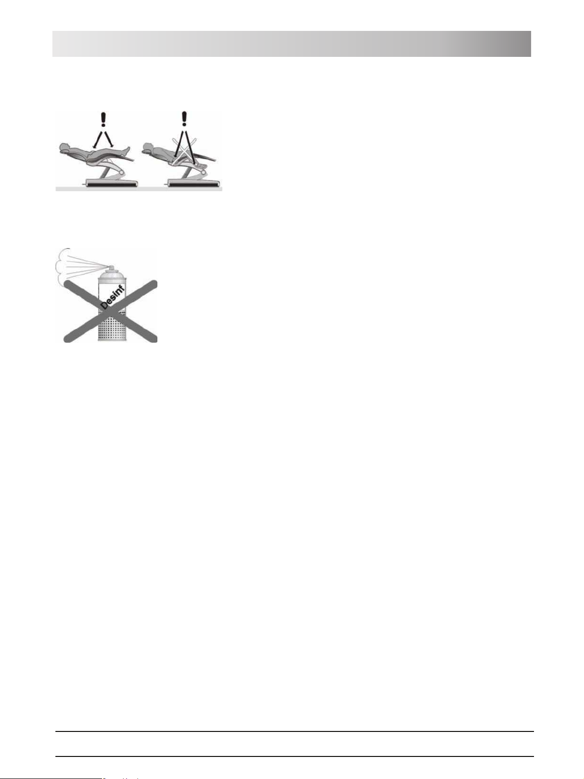
2.9 Ventilation slots
Under no circumstances may the ventilation slots on the unit be covered,
since otherwise the air circulation will be obstructed. This may cause the unit
to overheat.
Do not spray liquids such as disinfectants into the ventilation slots. This could
cause the unit to malfunction. Use only wipe disinfection in the vicinity of the
ventilation slots.
2.10 Intermittent operation
The motors of the treatment center and of the treatment instruments are
designed for intermittent operation corresponding to the dental mode of
treatment.
Drive motors for patient chair and backrest: Max. 6% on-load factor, cycle
duration 425s
Other motors: ≥ 6% on-load factor, cycle duration 250s
SiroCam digital intraoral camera: 1min on / 3min off
2.11 Touchscreen
The monitor of the dentist element is equipped with touch-sensitive control
technology.
The touchscreen must not be operated with pointed objects such as ball-point
pens, pencils, etc. Such objects could damage or scratch its surface. Always
operate the touchscreen by pressing it gently with your fingertip.
2.12 Care and cleaning agents
Unsuitable care and cleaning agents may corrode the surface of the unit.
Therefore, use only care and cleaning agents which have been approved by
Sirona. For more information, please refer to "Care and cleaning agents" [
135].
61 93 556 D3509
D3509.201.01.02.02 19.09.2008
14

2 Safety information Sirona Dental Systems GmbH
Modifications and extensions of the system Operating Instructions TENEO
2.13 Modifications and extensions of the
system
Modifications to this system which might affect the safety of the system
owner, patients or other persons are prohibited by law.
For reasons of product safety, this product may be operated only with original
Sirona accessories or third-party accessories expressly approved by Sirona.
The user assumes the risk of using non-approved accessories.
If any devices not approved by Sirona are connected, they must comply with
the applicable standards, e.g.:
z IEC 60950 for information technology equipment (e.g. PC) and
z IEC 60601-1 for medical electrical equipment.
The treatment center monitor must fulfill the requirements of IEC 60950 and
IEC 60601-1.
The loudspeaker port of the monitor may be connected only to a device that
complies with IEC 60950 (e.g. a PC) or
IEC 60601-1. Under no circumstances may it be connected e.g. to a stereo
system, etc.
If a system is created during the installation process, the requirements of IEC
60601-1-1 must be fulfilled.
2.14 Electromagnetic compatibility
Medical electrical equipment is subject to special precautionary measures
regarding electromagnetic compatibility (EMC). It must be installed and
operated as specified in the document "Installation Requirements."
Portable and mobile RF communications equipment may interfere with
medical electrical equipment. Therefore, the use of such devices (e.g. mobile
phones) in practice or hospital environments must be prohibited.
The presence of electromagnetic interference in the vicinity of the treatment
center may cause image degradation and interruptions in the data
transmission via the USB interface to the PC. In those cases, repeat the
image acquisition or other actions.
In the event of heavy interference, it may be necessary to restart the PC. It is
therefore not recommended to use the PC for controlling other devices that
provide essential performance components.
2.15 HF surgery
This dental treatment center is available with a high-frequency surgical
device.
Only in the Federal Republic of Germany: The system owner is obliged to
keep a “Medical Product Log” if any HF surgical equipment is installed! For
more information, refer to "Safety tests for systems with HF surgical
equipment" [ 171].
15 D3509.201.01.02.02 19.09.2008
61 93 556 D3509

Sirona Dental Systems GmbH 2 Safety information
Operating Instructions TENEO Dismantling/Installation
2.16 Dismantling/Installation
Observe the installation instructions
When dismantling and reassembling the system, proceed according to the
installation instructions for new installation in order to guarantee its
functioning and stability.
61 93 556 D3509
D3509.201.01.02.02 19.09.2008
16
Sirona Dental Systems GmbH 3 System description
Operating Instructions TENEO Standards/Approvals
3 System description
3.1 Standards/Approvals
Certification
The TENEO® treatment center complies with the following standards:
z IEC 60601-1 (electrical and mechanical safety)
z IEC 60601-1-2 (electromagnetic compatibility)
z IEC 60601-1-4 (software)
z IEC 60601-1-6 (serviceability)
z IEC 60601-2-2 (HF surgery)
z ISO 6875 (Patient chair)
z ISO 9680 (Operating light)
z ISO 11143 (Amalgam separator), see also below
z EN 1717 (Connection to the drinking water system), see also below
Original language: German
This product bears the CE mark in accordance with the provisions of the
Council Directive 93/42/EEC of June 14, 1993 concerning medical devices
(MDD).
0123
The treatment center meets the requirements of the Canadian Standards
Association (CSA) according to CAN/CSA-C22.2 No. 601.1-M90
(AM 1 + AM 2), provided the CSA mark is attached on the type plate.
The amalgam separator achieves a separation efficiency of >98%. It therefore
meets the requirements of the standard ISO 11143 and the German Institute
for Structural Engineering (DIBT). The amalgam separator bears the Ü mark
of the DIBT and the AFNOR mark (of the French Standards Institute).
The treatment center complies with the technical rules and requirements on
safety and hygiene for connection to the public drinking water supply. The unit
is certified according to the requirements of the DVGW (Deutscher Verein für
Gas und Wasser = German Gas and Water Association). The unit thus fulfills
the requirements of EN 1717.
The current approvals are listed on the rating label of the patient chair.
The wireless modules in the wireless foot control and in the treatment center
meet the requirements of the R&TTE directive 1999/5/'EC. Standards:
z EN 60950-1
z EN 301489-1, EN 301489-17, EN 300328
The modules meet the requirements of the Federal Communications
Commission (Part 15 of the FCC Rules).
FCC ID: SIFNANOLOCAVR0108
®
TENEO
is a registered trademark of Sirona Dental Systems GmbH.
61 93 556 D3509
D3509.201.01.02.02 19.09.2008
17
3 System description Sirona Dental Systems GmbH
System overview Operating Instructions TENEO
3.2 System overview
The treatment center comprises the following main components:
A Patient chair [ 19]
B Motor-driven headrest [ 19] (shown here) or MultiMotion
headrest [2 20]
C Foot control [ 21] (with cable or wireless link)
D Dentist element [ 22]
E Assistant element [ 27]
F Water unit [ 29]
G Media block [ 30] and power switch [2 32]
18 D3509.201.01.02.02 19.09.2008
61 93 556 D3509
Sirona Dental Systems GmbH 3 System description
Operating Instructions TENEO Patient chair
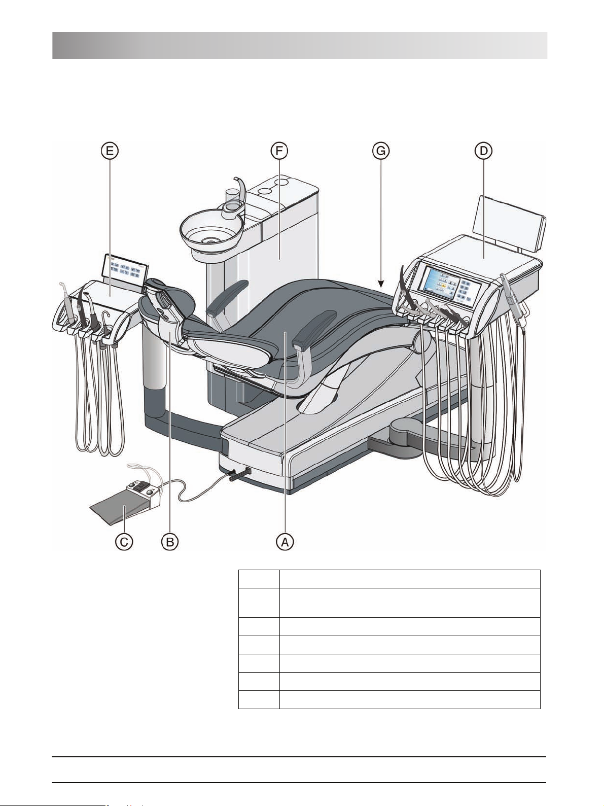
3.3 Patient chair
The patient chair features a variety of motor adjustment options to optimally
adapt the patient's position to the given treatment.
A
J
A Motor-driven headrest (shown here) or MultiMotion headrest
B
I
H
C
D
E
G
F
B Backrest
CSeat
D Armrest
E Toeboard
F Chair base
G Travel track for dentist element
H4-way foot switch
I Foot control cable port
J Rotary joint for assistant element
3.4 Headrest
3.4.1 Motor-driven headrest
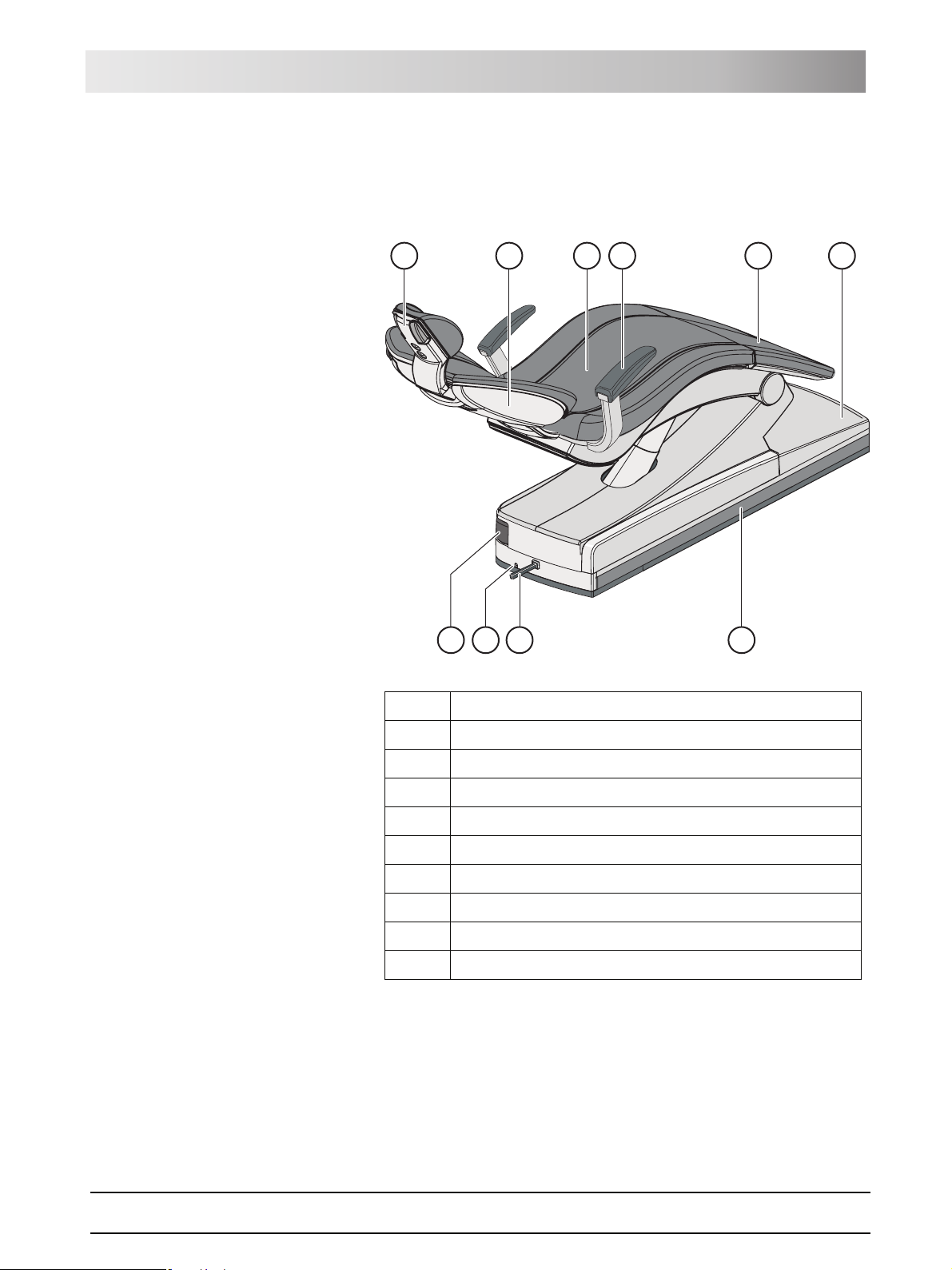
The headrest allows for the following adjustment options:
z Motor-driven extension/retraction to adapt to the patient's stature
z Motor-driven tilting for maxillary/mandibular treatment
61 93 556 D3509
D3509.201.01.02.02 19.09.2008
19
3 System description Sirona Dental Systems GmbH
Headrest Operating Instructions TENEO
z Manual tilting via quick mechanical adjustment
z Shifting/rotation of the head support via the magnetic holder
A
B
C
D
A Removable head pad with magnetic holder
B Quick mechanical adjustment of headrest tilt
C Upper 4-way switch for headrest functions
D Lower 4-way switch for chair functions
For details, see "Adjusting the motor-driven headrest" [ 46].
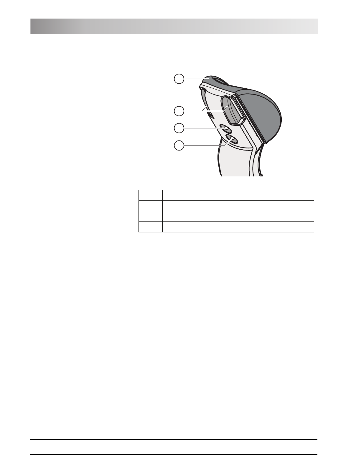
3.4.2 MultiMotion headrest
The MultiMotion headrest enables optimal access to the patient. The
following settings are possible:
z Retraction/extension of the headrest extension to adjust the headrest to
the patient's stature
z Adjustment of head inclination for maxillary/mandibular treatment
z Rotation of patient's head about the longitudinal axis of his body
z Lateral inclination of the patient's head
20 D3509.201.01.02.02 19.09.2008
61 93 556 D3509
Sirona Dental Systems GmbH 3 System description
S
0
Operating Instructions TENEO Foot control
A Removable head pad
B Operating handle for tilt adjustment
C Release button (concealed) for rotation and lateral tilt
D Headrest extension for stature adjustment
E Release button for removing the headrest
For details, see "Adjusting the MultiMotion headrest" [ 47].
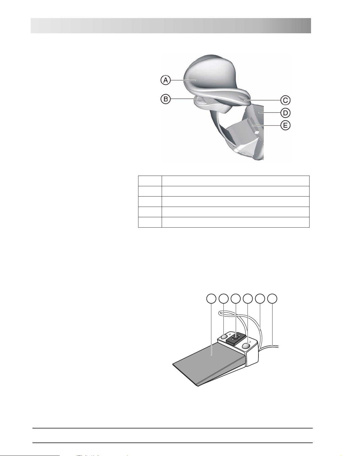
3.5 Foot control
The foot control enables hand-free control of the treatment instruments. Via
the integrated cursor control, virtually all functions of the treatment center can
be controlled via the foot control as an alternative to hand control.
E
A
B
C
D
F
61 93 556 D3509
D3509.201.01.02.02 19.09.2008
21

3 System description Sirona Dental Systems GmbH
Dentist element Operating Instructions TENEO
A Foot pedal as speed foot control or direct starter
B Left button (program key S or spray)
C 4-way foot switch plate for cursor control
D Right button (program key 0 or chip blower)
E Positioning bar
F Connecting cable
The foot control is also available with radio transmission. The connecting
cable has been omitted for the wireless foot control. The power supply is
provided by a battery.
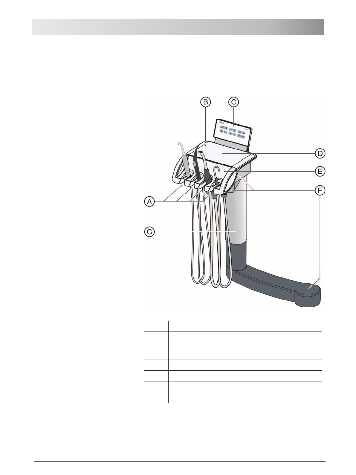
3.6 Dentist element
All functions of the treatment center can be controlled via the EasyTouch
control panel on the dentist element. The dentist element is moved via a
motor-driven travel track.
22 D3509.201.01.02.02 19.09.2008
61 93 556 D3509
Sirona Dental Systems GmbH 3 System description
Operating Instructions TENEO Dentist element
A Removable instrument holder (max. 6 instruments)
B Removable handles (left/right)
C Touchscreen for display and operation
D Fixed keys
EMain switch
FX-ray viewer
G Skid-proof silicone mat
H Additional holder for intraoral camera
I Support arm, height-adjustable
J Slide of motor-driven travel track
3.6.1 Instrument positions
The following instrument position assignments are possible:
Holder 1 Holder 2 Holder 3 Holder 4 Holder 5 Holder 6 Extra holder
SPRAYVIT L
multifunctional
syringe
1
Motor:
• SL
• BL
• BL ISO
• BL Implant
Turbine Turbine Turbine Turbine SIROTOM HF
1
Motor:
• SL
• BL
• BL ISO
• BL Implant
1
Motor:
• SL
• BL
• BL ISO
• BL Implant
1
Motor:
• SL
• BL
• BL ISO
• BL Implant
SIROSONIC
TL2 scaler
SiroCam digital
intraoral
camera
electrosurgical
handpiece
SIROSONIC
2
scaler
TL
SiroCam digital
intraoral
camera
1
The SL motor and the motors from the BL line cannot be combined.
2
A maximum of one SIROSONIC TL scaler can be connected.
3.6.2 EasyTouch user interface
61 93 556 D3509
D3509.201.01.02.02 19.09.2008
23
3 System description Sirona Dental Systems GmbH
Dentist element Operating Instructions TENEO
A Touchscreen (pressure-sensitive user interface)
B Fixed keys (membrane keyboard)
3.6.3 Touchscreen
The touchscreen displays virtual function keys according to the program
selected. A list of all function keys is provided in the Appendix of this
document, see "Overview of all function keys" [ 179].
Some programs are divided into a main program and sub-screens. The main
programs are briefly introduced below:
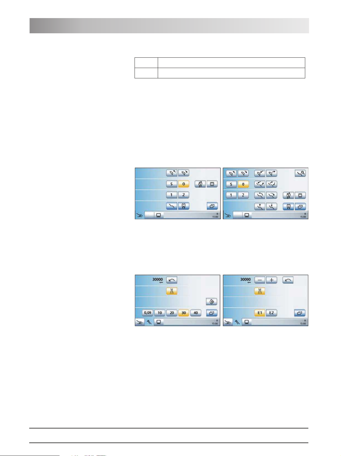
Start program The Start program can be displayed in the Simple Start program or Advanced
Start program operating mode. Details on both operating modes, see "Simple/
Advanced Start program" [ 44].
Simple Start program operating mode (left) and Advanced Start program
operating mode (right)
Instrument program The Instrument program matching the instrument currently removed is
displayed. The Instrument programs can be displayed either with the quick
setting keys or via the function levels. For details, see "Quick setting keys and
function levels" [ 62].
Motor screen with quick setting keys (left) and function levels (right)
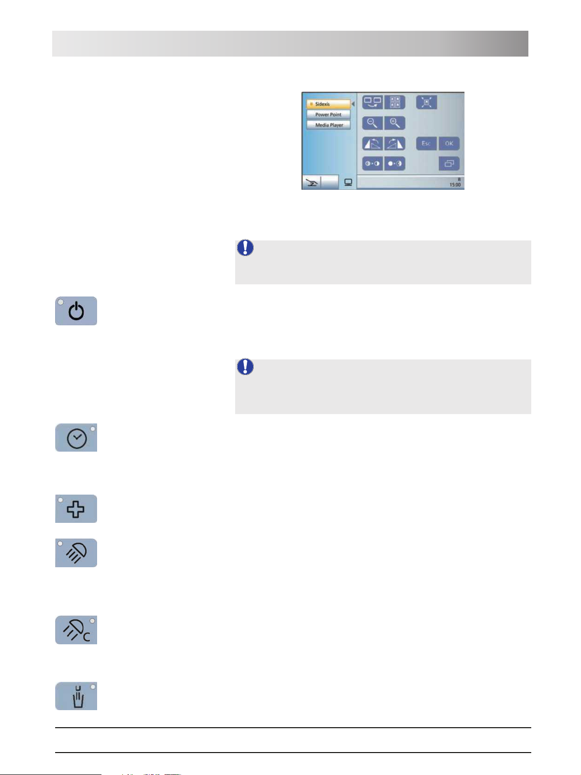
SIVISION program The SIVISION program enables the control of certain computer programs
running on the external PC directly from the treatment center. For details, see
"External PC" [ 119].
24 D3509.201.01.02.02 19.09.2008
61 93 556 D3509
Sirona Dental Systems GmbH 3 System description
Operating Instructions TENEO Dentist element
SIVISION program
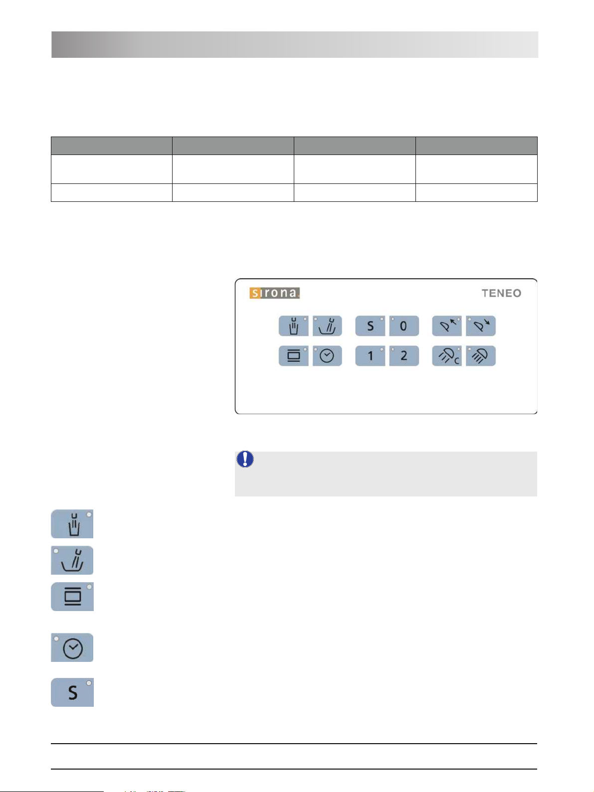
3.6.4 Fixed keys on the dentist element
NOTE: Detailed description
For a more detailed description of the fixed key functions, see "Fixed keys on
the dentist element" [ 57].
Fixed keys on the dentist element
Main switch
Switches the treatment center on/off.
To switch off, press and hold the key until an acoustic signal sounds. Then
release the key.
NOTE: Power switch
The treatment center also features a power switch on the base of the chair
that separates the treatment center from the power supply, see "Switching the
treatment center on/off" [ 32].
Timer function
Opens the Timer Function screen where any of six preset timers can be
activated. The time lapse is displayed in the footer of the touchscreen.
When the Timer Function key is pressed (> 2 s), the Timer Function settings
screen appears.
Shock positioning
Immediately moves the patient chair to a position for shock positioning of the
patient.
Operating light
Switches the operating light on/off.
Light intensity > 24,000 lux at 100%
When the operating light key is pressed (> 2 s), the Light Intensity settings
screen appears.
Composite function
Switches the composite setting for the operating light on/off.
This function is required to prevent premature curing of composite fillings.
61 93 556 D3509
D3509.201.01.02.02 19.09.2008
Reduced light intensity < 8,000 lux
Tumbler filling
Starts the tumbler filling function.
25
3 System description Sirona Dental Systems GmbH
Dentist element Operating Instructions TENEO
When the Tumbler filling key is pressed (> 2 s), the filling time and water
heating settings screen appears.
Flushing
Starts the flushing of the cuspidor bowl.
When the Flushing key is pressed (> 2 s), the Flushing Time settings screen
appears.
Freely selectable function
e.g. call key
freely available relay 230 VAC, 6 A
(connected by the service engineer).
This function can be preset as a button or as a switch in the Setup program.
Freely selectable function
freely available relay 230 VAC, 6 A
(connected by the service engineer).
This function can be preset as a button or as a switch in the Setup program.
Clean key
Pressing this key deactivates the complete user interface of the dentist
element. Pressing it again > 3 s reactivates the control panel.
This is used to make sure that no unwanted functions can be accidentally
triggered while cleaning the surface.
Setup key
Used for individual configuration of the treatment center by the user and for
reading out messages by the service engineer, see "Configuration of the
treatment center (Setup)" [ 123].
26 D3509.201.01.02.02 19.09.2008
61 93 556 D3509
Sirona Dental Systems GmbH 3 System description
Operating Instructions TENEO Assistant element
3.7 Assistant element
The functional scope of the assistant element is adapted to the dental
assistant's field of activity. It can, however, also be positioned so as to enable
unassisted treatment by the dentist.
61 93 556 D3509
D3509.201.01.02.02 19.09.2008
A Holders 1 to 4 (from left to right) for instruments
B Position of the hydrocolloid connection (concealed, under the
assistant element)
C User interface
D Skid-proof silicone mat
E Removable instrument holder
F 3 rotary joints for flexible positioning (partially concealed)
G Support arm, height adjustable by service engineer
27
3 System description Sirona Dental Systems GmbH
Assistant element Operating Instructions TENEO
3.7.1 Instrument positions
The following instrument position assignments are possible:
Holder 1 Holder 2 Holder 3 Holder 4
Mini L.E.D. curing light
Surgical suction device
SPRAYVIT L multifunctional
syringe
If the assistant element is equipped with a hydrocolloid connection, the
surgical suction device cannot be installed.
3.7.2 User interface
3.7.3 Fixed keys on the assistant element
Spray aspirator Saliva ejector
NOTE: Detailed description
For a more detailed description of the fixed key functions, see "Fixed keys on
the assistant element" [ 100].
Fixed keys on the assistant element
Tumbler filling
on/off
Flushing of the cuspidor bowl
on/off
X-ray viewer
on/off
This key has no function on the version not equipped with an X-ray viewer.
Timer function
Triggers the time lapse of the first timer. The timer is set on the dentist
element.
Chair program S
Mouth rinsing position with memory function (freely programmable)
28 D3509.201.01.02.02 19.09.2008
61 93 556 D3509
Sirona Dental Systems GmbH 3 System description
Operating Instructions TENEO Wate r uni t
Chair program 0
Entry/exit position (freely programmable)
Chair programs 1 and 2
(freely programmable)
Headrest
Moves the motor-driven headrest out/in for size adjustment. These keys do
not function if a MultiMotion headrest is installed.
Composite function
Switches the composite setting for the operating light on/off.
Reduced light intensity < 8,000 lux
Operating light
on/off
Light intensity > 24,000 lux at 100%
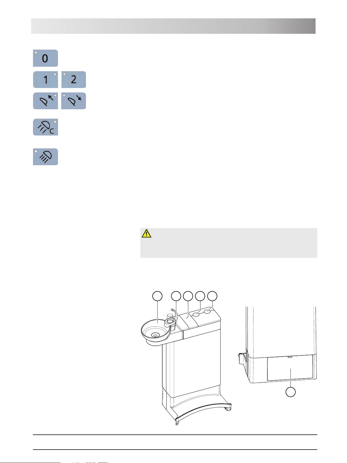
3.8 Water unit
The water unit is equipped with a disinfection system. It adds a disinfectant to
the water the patient comes in contact with. This reduces the amount of germs
in the water lines.
Germs in water lines
WARNING: Microorganisms can multiply in the water.
These microorganisms could increase the risk of damage to one's health.
¾ Never operate the treatment center without disinfectants.
The water unit can be optionally equipped with an automatic separator
(separation of suction air and waste water) combined with an amalgam
separator/sediment container or with a wet suction device.
E
A
B
C
D
61 93 556 D3509
D3509.201.01.02.02 19.09.2008
F
29
3 System description Sirona Dental Systems GmbH
External device connection Operating Instructions TENEO
A Swiveling cuspidor bowl
B Tumbler filler (depicted) or tumbler filler with automatic sensor
control for automatic filling of the tumbler
C Maintenance cover for disinfectant
D Mount for support arm of operating light
E Mount for tray support arm
F Maintenance flap for accessing flushing valve, amalgam
separator, sediment container or filter insert for wet suction
3.9 External device connection
External medical accessories can be connected to the external device
connection. They must comply with the requirements of Medical Device
Directive 93/42/EEC.
Connecting additional de vices
CAUTION: Additional devices connected to the external device
connection are exposed to a hydrogen peroxide concentration of 0.1‰-
0.2‰.
If the additional devices are not suitable for the specified hydrogen peroxide
concentration, they may be damaged.
¾ Before connecting any additional devices, check to make sure that they
can be exposed to a hydrogen peroxide concentration. Contact the
manufacturer of the relevant additional device, if necessary.
¾ Additional devices must not be sanitized with the treatment center, see
"Sanitizing the treatment center" [ 162].
NOTE: DVGW approval
Due to the design of the treatment center according to EN 1717/DIN 1988
(DVGW requirements) the connected additional devices fulfill the above
standards.
NOTE: Self-contained power supply
The inlet connector remains live when the power switch is turned off. The
connected external devices must therefore possess their own power switch.
However, the air and water connections are switched off.
30 D3509.201.01.02.02 19.09.2008
61 93 556 D3509

Sirona Dental Systems GmbH 3 System description
Operating Instructions TENEO External device connection
WATER AIR
Max.6A
FuseT6.3AH250~
A
B
C
D
A Inlet connector with power supply (max. 6 A)
B Fuse for inlet connector (6.3 A slow-blow)
C Quick coupling for water
D Quick coupling for air
Pressure Flow rate
Water 2,2 ± 0,2 bar max. 300 ml/min
Air 4,4 ± 0,5 bar max. 70 Nl/min
61 93 556 D3509
D3509.201.01.02.02 19.09.2008
31

Sirona Dental Systems GmbH 4 Operation
Operating Instructions TENEO Starting up the treatment center
4 Operation
4.1 Starting up the treatment center
4.1.1 Initial startup
Sanitation must be performed prior to initial startup of your treatment center.
This is done by filling all water-bearing lines with a concentrated disinfectant
to reduce the exposure of the water to bacteria.
If the service engineer skipped the sanitation procedure after installing your
treatment center based on an agreement with you or sanitation has not been
performed for more than one week, please perform sanitation yourself. Refer
to "Sanitizing the treatment center" [ 162] for more information.
Sanitation takes approx. 24 hours.
4.1.2 Switching the treatment center on/off
The treatment center is equipped with a standby system for enhanced
convenience when switching it on and off.
The treatment center thus features a power switch at the base of the chair and
a main switch on the dentist element.
4.1.2.1 Power switch
The power switch connects the treatment center to the power supply. During
longer periods of disuse, the treatment center should be disconnected from
the power supply. It then no longer consumes any energy.
The power switch contains an automatic device fuse.
Connecting the treatment center to the power supply
9 The treatment center is installed according to the "Installation
IR
A
WATER
50~
2
ax.6A
M
seT6.3AH
Fu
OFF
A
ON
Instructions" by authorized technical personnel.
¾ Turn on power switch A.
ª The treatment center is connected to the power supply.
Disconnecting the treatment center from the power supply
9 The treatment center is shut down, see "Switching the treatment center
off" (below).
¾ Turn power switch A off.
ª The treatment center is disconnected from the power supply.
4.1.2.2 Main switch
Switching the treatment center on
The main switch switches the treatment center from the Standby mode to
operational readiness.
61 93 556 D3509
D3509.201.01.02.02 19.09.2008
Following switch-on, the operating system is booted and an automatic selftest is performed.
32

4 Operation Sirona Dental Systems GmbH
Starting up the treatment center Operating Instructions TENEO
9 The power switch is turned on.
¾ Press the main switch on the dentist element.
ª The LED of the main switch lights up on the dentist element.
ª The treatment center powers up and establishes operational readiness.
NOTE: Maintenance deadline
If the next maintenance call is due in less than 42 days or the maintenance
deadline has already been exceeded, a message appears on the
touchscreen. For more information, please refer to "Inspection and
maintenance" [ 170].
Switching the treatment center to the Standby mode
On completing your work, you should switch the treatment center off with the
main switch on the dentist element both for safety reasons and to reduce its
power consumption. Pressing the main switch turns the air and water supply
as well as all electronic components off. Only the Standby circuit (power
consumption 3 W) is still supplied with voltage.
¾ Press and hold the main switch on the dentist element until an acoustic
signal sounds. Then release the key.
ª The treatment center then shuts down and switches itself to the Standby
mode.
ª The LED of the main switch goes out on the dentist element.
4.1.3 Selecting a user profile
The treatment center enables you to manage up to six user profiles. Multiple
users can operate the treatment center without having to do without their own
individual treatment and operation related settings.
The following is stored in the user profiles:
z Creation of chair programs, see "Creating chair programs and shock
positioning" [ 55]
z Configurations in the Setup programs, see "Configuration of the treatment
center (Setup)" [ 123]
z Settings in the start and Instrument programs, see "Saving the instrument
settings" [ 63]
z Configuration of the SIVISION screen for PC control. The configuration is
saved in the PC application SIUCOM plus that is installed on the external
PC.
Once the user profile has been selected, the corresponding configurations
and settings become available once again.
If any of the user profiles are not required, their number can be limited, see
"Preselecting the number of user profiles" [ 127].
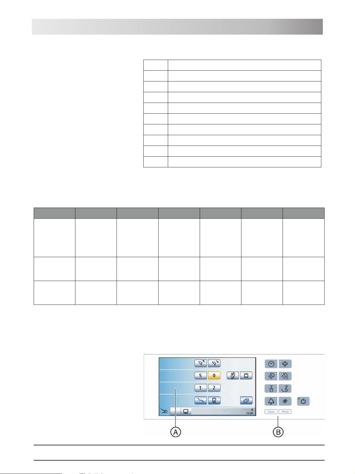
The user profiles (A) are distinguished with the letters A to F. The active user
profile, here B, is displayed in the footer of the touchscreen. The user profile
used last is automatically used when the treatment center is switched on.
33 D3509.201.01.02.02 19.09.2008
61 93 556 D3509

Sirona Dental Systems GmbH 4 Operation
Operating Instructions TENEO Control concept of touchscreen
9 The Start program is displayed on the touchscreen in the Simple (shown
here) orAdvanced Start program mode, see "Simple/Advanced Start
program operating mode" [ 44].
¾ Select the desired user profile. Touch the User profile key as often as
necessary.
ª The user profile displayed in the footer is active.
4.2 Control concept of touchscreen
The touchscreen displays virtual function keys according to the program
selected. Required functions can be triggered either by touching the function
keys with your finger or via cursor with the foot control.
The adjacent illustration shows the touchscreen of a treatment center as
supplied to the customer and maximally equipped.
NOTE: Missing function keys
Function keys for functions which the treatment center is not equipped with
are not displayed on the touchscreen. Moreover, the touchscreen user
interface can be altered via individual Setup changes, see "Configuration of
the treatment center (Setup)" [ 123].
Footer
The three program change keys on the bottom left edge of the touchscreen
can be used to change between the following main programs:
z Start program
z Instrument program
z SIVISION program
The selected program is highlighted blue.
If a symbol of a program change key is hidden, the corresponding main
program cannot be selected in the current operating state. It is not possible:
z to change to the Instrument program if no instrument has been withdrawn
from its holder
z to change to the SIVISION program if the PC connection has been
switched off or is not configured.
Connection errors involving the external PC are marked by a warning
triangle, see below.
In the sub-screens or settings screens (see below), all main programs are
shaded gray in the footer. You can change from sub-screens and settings
screens to a main program by touching one or the three keys.
61 93 556 D3509
D3509.201.01.02.02 19.09.2008
A status bar is located on the right. If multiple user profiles (A) are
preselected, active user profiles A to F are displayed along with the current
time underneath.
34

4 Operation Sirona Dental Systems GmbH
Foot control Operating Instructions TENEO
Status messages are displayed to indicate e.g. failure to communicate with
the external PC, the need to change the amalgam separator or add
disinfectant, the need to charge the battery of the wireless foot control, error
messages, or the number of days left until the next maintenance call or
sanitation run.
If the treatment function is switched on, the selected treatment and the
assigned burr drive are also displayed here.
Sub-screens
Some programs are divided into a main program and sub-screens.
The function keys for the basic functions are displayed in the main programs.
The Sub-screen key (two rectangles) leads to further setting possibilities.
Sub-screens are automatically hidden after a certain period has elapsed. The
Return key (return arrow) closes the opened sub-screen immediately.
Settings screens
In many cases, functions not only can be switched on or off, but also can be
set. If a function key is pressed and held (> 2 s), the corresponding settings
screen appears. This screen is superimposed onto the one lying below it. The
screen located in the background has a semitransparent appearance and is
temporarily disabled for inputs.
Settings screens are automatically hidden after a certain period has elapsed.
The Return key (return arrow) closes the opened settings screen
immediately.
Key background colors
General functions are represented by gray keys. If the corresponding function
is switched on or active, the key is displayed orange.
Keys that initiate a program change or lead to sub-screens and settings
screens are displayed blue.
As long as a key remains activated, its active state is marked by a bold black
border.
4.3 Foot control
The treatment center can be operated using a wireless foot control or a foot
control with a cable connection.
4.3.1 Wireless foot control
Technical data of the wireless module, see Foot control radio interface" [
177].
35 D3509.201.01.02.02 19.09.2008
61 93 556 D3509

Sirona Dental Systems GmbH 4 Operation
S
0
S
0
Operating Instructions TENEO Foot control
4.3.1.1 Setting the wireless foot control on the treatment
center
The wireless foot control must be assigned to the treatment center via a
registration. This prevents malfunctions caused by neighboring wireless foot
controls.
9 The treatment center and wireless foot control are ready for operation.
9 All instruments are in place.
1. Simultaneously press and hold the left and right buttons of the foot control
S
0
(> 2 s).
ª An acoustic signal sounds. The following message appears on the
touchscreen:
2. Confirm that this wireless foot control is to be used on the treatment
center by pressing the OK button. The registration process can be
interrupted with the Esc key.
ª The message is hidden. The wireless foot control is assigned to the
treatment center.
61 93 556 D3509
D3509.201.01.02.02 19.09.2008
4.3.1.2 Battery voltage message
The wireless foot control is powered by a battery. An almost empty battery is
detected by the system and displayed in the footer. The battery should then
be replaced within a week to prevent system failure.
When the battery is completely empty, an error code is output, see "Error
messages" [ 172]. Then the treatment center can no longer be operated.
The battery can be changed by the user, see "Changing the battery of the
wireless foot control" [ 168].
4.3.2 Operating the foot control
The foot control operating elements are assigned different functions,
depending on whether the instruments are all deposited or an instrument is
removed from its holder.
Foot pedal
9 All instruments are in place.
¾ Step on the foot pedal.
ª The dentist element moves toward the operator as long as the pedal
is actuated
9 An instrument is removed.
¾ Step on the foot pedal.
ª The instrument is activated. The intensity is regulated according to
the pedal movement if necessary (if the speed foot control is set, see
"General instrument functions" [ 64]). If the intraoral camera is removed,
the display switches to the still or live image.
36

4 Operation Sirona Dental Systems GmbH
S
0
S
0
S
0
S
0
Foot control Operating Instructions TENEO
4-way foot switch plate
If the cursor control is switched on, it is operated via the 4-way foot switch
plate, see "Using the cursor control" [ 38].
If the cursor control is switched off, then:
9 All instruments are in place.
¾ Slide the 4-way foot switch plate upward.
ª The dentist element moves toward the foot end as long as the pedal is
actuated.
9 An electric motor is removed.
¾ Slide the 4-way foot switch plate to the right or left.
ª The CW/CCW rotation of the electric motor is activated.
Left button
9 All instruments are in place.
S
¾ Press the left button.
ª The chair moves to mouth rinsing position S.
9 An instrument (motor, turbine, SIROSONIC TL) is removed.
¾ Press the left button.
ª Spray or NaCl is switched on/off. If the intraoral camera is removed,
the video still image is saved.
NOTE: Allocation of additional functions
Users can allocate additional functions to this key that correspond to the
position of the blue cursor, see also "Using the cursor control" [ 38].
Right button
9 All instruments are in place.
0
¾ Press the right button.
ª The chair moves to entry/exit position 0.
9 An instrument (motor, turbine) is removed.
¾ Press the right button.
ª The chip blower remains switched on as long as the button is
pressed. If the intraoral camera is removed, the video still image is saved.
NOTE: Allocation of additional functions
Users can allocate additional functions to this key that correspond to the
position of the blue cursor, see also "Using the cursor control" [ 38].
61 93 556 D3509
37 D3509.201.01.02.02 19.09.2008

Sirona Dental Systems GmbH 4 Operation
S
0
Operating Instructions TENEO Foot control
4.3.3 Using the cursor control
4.3.3.1 Functionality
Cursor control as an alternative mode of operation
The touchscreen and the fixed keys of the dentist element can also be
operated hand-free via the foot control. This method of operation optimally
supports hygiene, especially in connection with sterile treatment work.
For cursor control, the foot control features a 4-way foot switch plate that can
be moved in four directions.
The cursor position is optically displayed on the touchscreen or on the fixed
keys.
The cursor control is reserved for the Start and Instrument programs. The
SIVISION programs cannot be controlled via the cursor.
Cursor control setting options
Note that different settings can be made for the cursor control in the Setup
program. The functions assigned to the 4-way foot switch plate vary
according to its setting. The adjacent symbols for setting the cursor are used
in the Setup program.
z Cursor control switched off:
The dentist element moves away from the user when the 4-way foot
switch plate is pressed upward. Counterclockwise or clockwise motor
rotation can be selected by sliding the 4-way foot switch plate to the left or
right.
z Cursor control switched on, without program change:
The cursor can be moved along the cursor path by holding or repeating
upward or downward actuation of the 4-way foot switch plate.
z Cursor control switched on, with program change:
The cursor can be moved along the cursor path by holding or repeating
upward or downward actuation of the 4-way foot switch plate. If the cursor
is located at the end of the cursor path, it can be toggled between the Start
program and the Instrument program.
Please also note the information on "orange and blue bars," see below.
To set the cursor control to the mode you prefer, refer to "Setting the cursor
control" [ 126].
61 93 556 D3509
D3509.201.01.02.02 19.09.2008
Current cursor position
If the cursor control is activated, the current position of the cursor is displayed
by an orange bar located between the pairs of keys on the touchscreen or
between the fixed keys on the EasyTouch control panel.
38

4 Operation Sirona Dental Systems GmbH
S
0
S
0
S
0
Foot control Operating Instructions TENEO
Cursor path
The cursor path runs between the pairs of keys, moving from top to bottom
and from left to right, usually in multiple loops. The cursor path can be
traversed between the starting and end points either in a forward or a reverse
direction.
If no further cursor position is available on the touchscreen, the cursor jumps
out of the touchscreen. The cursor path is then continued between the fixed
keys on the EasyTouch control panel.
In Instrument programs, all quick setting keys are selected simultaneously.
This is indicated by a horizontal orange bar located behind the quick setting
keys. The speed or intensity is then set by actuating the 4-way foot switch
plate to the left or right briefly (values on quick setting keys) or for a longer
time (intermediate values), see "Operating the cursor control" [ 39].
The Clean key, Setup routine and main switch cannot be accessed via the
cursor control.
Orange and blue bars
A blue bar indicates which functions are assigned with the left or right button
S
0
of the foot control. For example, the mouth rinsing position (S) and entry/exit
position (0) chair programs are assigned in the Start program, while the Spray
and Chip blower are assigned in the Instrument program.
If the cursor control without program change is activated, the blue bars also
can be selected with the cursor. If the cursor control with program change is
activated, the blue bars are skipped for faster navigation.
Chip blower key in the Instrument program
When the cursor control is activated, the instrument program will display the
Chipblower key.
4.3.3.2 Operating the cursor control
Moving the cursor
¾ Briefly slide the 4-way foot switch plate upward or downward.
ª The orange cursor moves forward or back one cursor position.
¾ Hold the 4-way foot switch plate up or down (auto cursor).
ª The orange cursor slowly moves from one cursor position to another.
61 93 556 D3509
39 D3509.201.01.02.02 19.09.2008

Sirona Dental Systems GmbH 4 Operation
S
0
S
0
S
0
Operating Instructions TENEO Patient chair
Actuating a function or fixed key
¾ Press left button: Slide the 4-way foot switch plate to the left.
Press the right button: Slide the 4-way foot switch plate to the right.
ª The selected key is highlighted orange on the touchscreen (if
switched on) resp. gray or blue (if switched off). The LED of the selected
fixed key lights up or goes out on the control panel of the dentist element.
Activating a quick setting key and setting intermediate values
Operation of the cursor control for screens with quick setting keys is illustrated
based on the example of the motor screen.
9 The cursor control is switched on.
1. Move the cursor to the quick setting keys.
ª The quick setting keys are highlighted with an orange bar.
2. Setting the values of the quick setting keys: Briefly move the 4-way foot
switch plate to the left or right.
Setting the intermediate values: Move the 4-way foot switch plate to the
left or right and hold it in this position.
ª The motor speed is displayed in the first line. If the motor is set to a
value corresponding to one of the quick setting keys, it is highlighted
orange.
Changing programs
9 Cursor control with program change is switched on.
1. Position the cursor at the starting point of the cursor path.
2. Move the cursor past the start position. Hold the 4-way foot switch plate
in the upward position.
ª The touchscreen display changes to the start or Instrument program.
4.4 Patient chair
4.4.1 Safety information
Chair movements
WARNING: The clearance between the chair upholstery and its
base may decrease during chair movements.
Parts of the patient's or user's body may be pinched or crushed.
¾ Make sure that no limbs protrude into the free space between the
upholstery and the base of the chair during chair movements. Also make
sure that the patient's arms and legs are resting on the chair's upholstery.
¾ Do not place any objects on the base of the chair.
61 93 556 D3509
D3509.201.01.02.02 19.09.2008
40

4 Operation Sirona Dental Systems GmbH
Patient chair Operating Instructions TENEO
Maximum load capacity of patient chair
WARNING: The maximum load capacity of the patient chair is 165
kg acc. to ISO 6875 (tested with multiple safety acc. to IEC 60601-1).
If the maximum load capacity is exceeded,a risk of damage to the treatment
chair and injury of the patient exists.
¾ Never allow any persons who weigh more than 160 kg to sit on the
patient chair.
¾ The maximum additional weight of accessories mounted on the patient
chair is 5 kg.
Obstacles in the movement range
WARNING: Objects protrude into the movement range of the chair.
There is a risk of crushing the patient and damaging the objects.
¾ Make sure that no objects such as e.g. windows, drawers or other
devices protrude into the movement range of the treatment center.
NOTE: Chair interlock
As long as a treatment instrument is activated, all functions for moving the
patient chair are disabled for safety reasons.
4.4.2 Safety stop
The treatment center is equipped with various safety stops to prevent
crushing. The cutoff trigger points are shown in the following illustration:
Display of triggered safety switches (all shown on one illustration)
A Assistant element support arm
B Cuspidor bowl
C Backrest
41 D3509.201.01.02.02 19.09.2008
61 93 556 D3509

Sirona Dental Systems GmbH 4 Operation
S
0
Operating Instructions TENEO Patient chair
D Armrest, right
E Manual switching strip front/rear, right/left
F Toeboard
G Rear housing, rear lift frame, front lift frame
right/left in each case.
The three safety switches are jointly displayed on the
touchscreen.
The following occurs when one or more safety switches is triggered:
z An acoustic signal sounds (if the movement is interrupted)
z All chair movements stop immediately
z The triggered safety switches are displayed on the touchscreen.
z A correction movement in the opposite direction is executed for approx. 3
seconds for movements of the patient chair (but not for movements of the
assistant element or the swiveling cuspidor) insofar as this clearly leads to
a reduction of the hazard.
As long as a safety switch is activated, the operation of the treatment center
is restricted.
If a safety switch is permanently blocked, please contact your service
engineer.
4.4.3 Triggering an immediate movement stop
You can stop the movement of the chair to a programmed position as follows:
¾ Press the main switch or the Shock positioning fixed key on the dentist
element.
¾ Touch one of the patient chair keys on the touchscreen.
¾ Press one of the patient chair keys on the control panel of the assistant
element.
¾ Press the left or right button of the foot switch with all instruments in
S
0
place.
61 93 556 D3509
D3509.201.01.02.02 19.09.2008
42

4 Operation Sirona Dental Systems GmbH
Patient chair Operating Instructions TENEO
¾ Actuate the 4-way foot switch in any direction.
¾ Actuate the 4-way switch on the motor-driven headrest in any direction.
ª All movements of the treatment center are stopped immediately.
4.4.4 Armrests
The patient chair can be equipped with armrests on both sides.
Left armrest
WARNING: The clearance between the left armrest and the water
unit is confined.
The patient's hand can be caught between the left armrest and the housing of
the water unit during chair travel.
¾ Make sure that the patient's hand always remains outside of the collision
area.
Swiveling the armrest
The armrest on the side of the dentist element can be swiveled out 90° for
easier entry and exit.
1. Press and hold the locking button behind the armrest.
ª The armrest is unlocked.
2. Swivel the armrest toward the rear or toward the front.
ª The armrest automatically engages in both end positions.
Removing/attaching the armrest
The right armrest is equipped with a safety switch that stops chair movement
immediately when the armrest is swiveled outward (risk of collision with the
dentist element)
43 D3509.201.01.02.02 19.09.2008
61 93 556 D3509

Sirona Dental Systems GmbH 4 Operation
Operating Instructions TENEO Patient chair
If the armrest is removed, the supplied cover must be inserted in the mount
on the patient chair instead of the armrest in order to bridge the safety switch.
If the safety switch is not bypassed with the cover when the armrest is
removed, the treatment center will be disabled by the triggered safety switch,
see also "Safety stop" [ 41].
1. Press and hold the release button on the bottom side of the armrest and
pull out the armrest.
2. Insert the cover instead of the armrest.
ª The cover automatically locks in place. The safety switch of the
armrest is bypassed.
Proceed in reverse order when installing the armrest. Press the tab of the
cover with one finger to release it from the side of the chair.
CAUTION: A swiveling armrest does not have an end stop that
would prevent a collision when fitted in the left-hand position.
Fitting a swiveling armrest in the left-hand position can lead to collisions with
the tumbler during certain chair movements.
¾ Only use the swiveling armrest on the right-hand side of the treatment
center.
4.4.5 Simple/Advanced Start program operating
mode
Function of the Start programs
In the Start program, you can select functions associated with movement of
the patient chair. Furthermore, you also can access additional general
functions via the Start program.
Difference between Simple and Advanced Start program modes
In the Simple Start program operating mode, only the chair program function
keys and, if present, the Move headrest in/out function are displayed in the
screen.
Simple Start program operating mode
In the Simple Start program operating mode, the remaining functions are
listed in the separate Manual Chair Adjustment screen. This is achieved via
the additional Manual Chair Adjustment key.
61 93 556 D3509
D3509.201.01.02.02 19.09.2008
44

4 Operation Sirona Dental Systems GmbH
Patient chair Operating Instructions TENEO
Manual Chair Adjustment screen (for Simple Start program mode only)
In the Advanced Start program mode, all function keys associated with
movement of the patient chair are displayed together in a single screen.
Advanced Start program operating mode
Missing function keys in the Start program
The screens displayed above show the function keys of a fully equipped
treatment center. Function keys for functions which the treatment center is not
equipped with are not displayed on the touchscreen. In the Start program this
includes function keys for the following equipment options:
z Motor-driven headrest
z Treatment (endodontics and implantology)
Furthermore, the screens may vary due to individual Setup settings. The
following configurations may influence the Start programs, see:
z "Showing/hiding" chair programs 3 and 4" [ 126]
z "Showing/hiding the fine adjustment key" [ 126]
z "Preselecting the number of user profiles" [ 127]
z "Setting the X-ray image viewer key to white screen on the SIVISION
monitor" [ 129]
Using the Simple/Advanced Start program operating mode
You can select the operating mode you prefer to use; see "Changeover
between Simple and Advanced Start program" [ 126].
Opening the Start program
After the treatment center is switched on the Start program automatically
appears in the selected operating mode.
If the treatment center is already in operation and the Start program is not
displayed, proceed as follows:
¾ Touch the Start program program change key in the footer of the
touchscreen.
45 D3509.201.01.02.02 19.09.2008
61 93 556 D3509

Sirona Dental Systems GmbH 4 Operation
Operating Instructions TENEO Patient chair
ª The Start program is displayed in the selected operating mode.
4.4.6 Adjusting the motor-driven headrest
The motor-driven headrest can be adjusted via the touchscreen or directly on
the headrest.
Motor-driven headrest
WARNING: Fine objects can enter the mechanism of the motor-
driven headrest through the gap.
Long hair, dangling jewelry or loosely fitting clothing can be pulled in.
¾ Position the patient in such a way that his/her hair and any objects he/
she is wearing cannot be pulled in.
4.4.6.1 Moving the headrest in/out
The treatment chair is adjusted to the patient's stature by moving the headrest
in or out.
Via touchscreen
9 The Start program is displayed on the touchscreen.
¾ Touch the Headrest in/out keys.
Via the assistant element
¾ Press the Headrest in/out fixed keys.
Via the 4-way switch
¾ Slide the upper 4-way switch upward or downward.
4.4.6.2 Inclining the headrest
The headrest can be tilted either via motor drive or manually (quick
mechanical adjustment).
Via touchscreen
9 The Manual Chair Adjustment screen or the Start program is displayed
on the touchscreen in the Advanced Start program operating mode.
¾ Touch the Tilt headrest keys.
61 93 556 D3509
D3509.201.01.02.02 19.09.2008
46

4 Operation Sirona Dental Systems GmbH
Patient chair Operating Instructions TENEO
Via the 4-way switch
¾ Slide the upper 4-way switch to the left or right.
Via quick mechanical adjustment
1. Hold the headrest securely in place before unlocking it.
A
A
2. Press buttons A together.
ª The headrest is thus disconnected from the motor drive and can be
tilted manually.
4.4.7 Adjusting the MultiMotion headrest
The MultiMotion headrest enables you to adjust the patient's head in a way
that optimally supports viewing of hard-to-access areas of the patient's
mouth.
4.4.7.1 Patient height adjustment
The headrest can be adjusted to the patient's height by pulling out or pushing
in the headrest extension.
NOTE: Treatment without readjustment
Before positioning the patient on the headrest, make sure that the head
support has been optimally adjusted to the patient's height. This simplifies all
subsequent work with the MultiMotion headrest considerably, since
readjustment to the patient's height can thus be omitted when changing over
from mandibular to maxillary treatment.
4.4.7.2 Setting the jaw position
The MultiMotion headrest enables you to change between the maxillary and
mandibular positions without adjusting the headrest extension. The
anatomical movement of the arched extension keeps the patient's head in the
support.
47 D3509.201.01.02.02 19.09.2008
61 93 556 D3509

Sirona Dental Systems GmbH 4 Operation
Operating Instructions TENEO Patient chair
1. Raise the headrest slightly by raising the operating handle.
ª The headrest is unloaded.
2. Press the release on the operating handle.
ª The lock for vertical adjustment is released.
3. Press and hold the release. Holding the headrest by the operating
handle, raise or lower it to the required position.
4. Let go of the the release on the operating handle.
ª The headrest is locked again.
4.4.7.3 Rotating and tilting the headrest
The MultiMotion headrest enables rotation of the patient's head about the
longitudinal axis of his body as well as lateral tilting of his head.
1. Press one or both of the lateral releases (A) on the headrest.
ª The lock for rotational and tilt adjustment is released.
2. Press and hold the releases (A). Set the headrest to the desired position.
3. Let go of the releases (A). Make sure that the headrest is indeed locked
in place after you let go of the releases!
ª The headrest is locked again.
4.4.7.4 Removing and inserting the headrest
For certain treatments (e.g. of children) it may be expedient to remove the
MultiMotion headrest completely in order to obtain better access to the
patient. The patient's head is then supported on a head pad. It is magnetically
attached to the headrest extension.
The head pad is not included in the scope of supply. It can be ordered from a
specialized dealer.
61 93 556 D3509
D3509.201.01.02.02 19.09.2008
48

4 Operation Sirona Dental Systems GmbH
Patient chair Operating Instructions TENEO
Head pad magnet
WARNING: The head pad contains a strong magnet on its bottom
side.
This magnet could affect any cardiac pacemaker located nearby.
Furthermore, direct contact of the head pad with magnetic cards can delete
data stored on the cards.
¾ Therefore, make sure that the magnet is never located in the immediate
vicinity of any patients, users or technical personnel wearing a cardiac
pacemaker.
¾ Make sure that no magnetic cards or any other data storage media are
located in the immediate vicinity of the head pad.
Removing the MultiMotion headrest
1. Press the release button (A).
2. Pull the complete headrest out of the headrest extension (C).
3. Cover the opening of the headrest extension with the cover cap (B).
4. If a children's head pad (D) is available, place it on the headrest
extension.
ª The head pad is held magnetically.
NOTE: Storage of the MultiMotion headrest
Store the MultiMotion in a safe place where it cannot fall onto the floor.
Inserting the MultiMotion headrest
1. Check the guide of the removed headrest for contamination and remove
any contamination you may find.
2. Remove the cover cap (B).
3. Reinsert the MultiMotion in the guide from above until it audibly locks in
place. Pull on the headrest again to make sure that it is locked securely
in place.
4.4.8 Moving the patient chair via chair programs
The chair programs can be selected via the touchscreen or via the user
interface of the assistant element. The entry/exit and mouth rinsing positions
can also be selected via the foot control.
You can individually reprogram the factory preset chair programs to suit your
own wishes; see "Creating chair programs" [ 55].
You can select the chair program during which the dentist element is to
approach the treatment center; see "Linking dentist element movement to
chair programs" [ 128].
49 D3509.201.01.02.02 19.09.2008
61 93 556 D3509

Sirona Dental Systems GmbH 4 Operation
S
0
Operating Instructions TENEO Patient chair
Cuspidor bowl moves to starting positi on
NOTE: The cuspidor bowl automatically swivels back to its starting
position
The cuspidor bowl automatically returns beforehand to ensure that the patient
does not collide with it during chair movements. This return travel is
dependent on the chair movement and is executed only if a collision hazard
exists.
4.4.8.1 Moving the patient chair to the entry/exit position
The following functions are triggered for simple patient entry and exit in the
entry/exit position:
z The patient chair moves to an upright position
z The dentist element moves to the foot end
z The operating light switches off
z The cuspidor bowl swivels out
The tumbler heater can be set so that it automatically switches off when the
entry/exit position (0) chair program is activated; see "Linking the tumbler
heater to the entry/exit position" [ 128].
Entry/exit position
WARNING: The patient's feet may get caught in the instrument
hoses of the dentist element when he enters or leaves the patient chair.
The patient may trip or fall.
¾ Turn the dentist element outward before the patient enters or leaves it.
Via touchscreen
9 The Start program is displayed on the touchscreen.
¾ Touch the 0 key briefly (< 2 s).
Via foot control
9 All instruments are in place.
0
¾ Press the right button of the foot control.
Via the assistant element
¾ Press the 0 key on the assistant element briefly (< 2 s).
4.4.8.2 Moving the patient chair to the mouth rinsing
position
61 93 556 D3509
D3509.201.01.02.02 19.09.2008
The following functions are triggered in the mouth rinsing position:
z The operating light switches off
z The chair moves the patient to an upright position
50

4 Operation Sirona Dental Systems GmbH
S
0
Patient chair Operating Instructions TENEO
This can be used to set the cuspidor bowl so that it automatically moves
inward when the mouth rinsing position (S) chair program is selected;
see"Linking the movement of the cuspidor bowl to the mouth rinsing position"
[ 127].
Via touchscreen
9 The Start program is displayed on the touchscreen.
¾ Touch the S key briefly (< 2 s).
Via foot control
9 All instruments are in place.
S
¾ Press the left button of the foot control.
Via the assistant element
¾ Press the S key on the assistant element briefly (< 2 s).
4.4.8.3 Using the last position memory function
The last chair position is stored before the patient chair moves to mouth
rinsing position S. When mouth rinsing position key S is pressed again, the
treatment center returns to the previously set treatment position.
9 The patient chair is located in any treatment position.
1. Press the S key on the touchscreen, or press the S key on the user
interface of the assistant element, or press the left button of the foot
control (with all instruments in place in their holders).
ª The treatment center moves to the mouth rinsing position.
2. Press the S key on the touchscreen, or on the user interface of the
assistant element, or press the left button of the foot control again.
ª The treatment center automatically returns to the position where the
patient chair was located prior to the mouth rinsing position.
4.4.8.4 Activating other chair programs
The number of chair programs can be extended to 4 or limited to 2; see
"Showing/hiding chair programs 3 and 4" [ 126].
Via touchscreen
9 The Start program is displayed on the touchscreen.
¾ Touch key 1, 2 or, if required, 3, 4 briefly (< 2 s).
61 93 556 D3509
51 D3509.201.01.02.02 19.09.2008

Sirona Dental Systems GmbH 4 Operation
Operating Instructions TENEO Patient chair
Via the assistant element
¾ Press key 1 key or 2 on the assistant element briefly (< 2 s).
NOTE:
Chair programs 3 and 4 cannot be selected on the assistant element.
4.4.9 Moving the chair manually
Cuspidor bowl moves to starting positi on
NOTE: The cuspidor bowl automatically swivels back to its starting
position
The cuspidor bowl automatically returns beforehand to ensure that the patient
does not collide with it during chair movements. This return travel is
dependent on the chair movement and is executed only if a collision hazard
exists.
4.4.9.1 Manual Chair Adjustment screen (for Simple Start
program mode only)
9 The Start program is displayed on the touchscreen with the Simple Start
program operating mode.
1. Touch the Manual Chair Adjustment key.
ª The Manual Chair Adjustment screen is displayed.
2. Perform the settings described in the following sections.
4.4.9.2 ErgoMotion – Tilting the patient couch and
inclining the backrest
Compensated motion of the seat and backrest without any compression or
stretching effects for the patient
Via touchscreen
9 The Manual Chair Adjustment screen or the Start program is displayed
on the touchscreen in the Advanced Start program operating mode.
¾ Touch the ErgoMotion keys.
61 93 556 D3509
D3509.201.01.02.02 19.09.2008
52

4 Operation Sirona Dental Systems GmbH
Patient chair Operating Instructions TENEO
Via the 4-way foot switch
¾ Slide the 4-way foot switch to the left or right.
Via the 4-way switch
¾ Slide the upper 4-way switch to the left or right.
4.4.9.3 OrthoMotion – Tilting the patient chair
Tilting motion of the patient chair without changing the angle between the seat
and backrest. This movement is particularly suitable for patients with limited
mobility.
9 The Manual Chair Adjustment screen or the Start program is displayed
on the touchscreen in the Advanced Start program operating mode.
¾ Touch the OrthoMotion keys.
4.4.9.4 Adjusting the chair height
Via touchscreen
9 The Manual Chair Adjustment screen or the Start program is displayed
on the touchscreen in the Advanced Start program operating mode.
¾ Touch the Chair height adjustment keys.
Via the 4-way foot switch
¾ Slide the 4-way foot switch upward or downward.
Via the 4-way switch
¾ Slide the lower 4-way switch upward or downward.
61 93 556 D3509
53 D3509.201.01.02.02 19.09.2008

Sirona Dental Systems GmbH 4 Operation
Operating Instructions TENEO Patient chair
4.4.9.5 Moving the patient chair with the fine adjustment
Depending on the type of treatment, it may be necessary to adjust the patient
chair more slowly and more precisely (e.g., for tiny corrections in case of
treatment under a microscope). In this case, the Fine Adjustment key can be
displayed in the Start program; see "Showing/hiding the fine adjustment key"
[ 126].
Fine adjustment on/off
9 The Manual Chair Adjustment screen or the Start program is displayed
on the touchscreen in the Advanced Start program operating mode.
9 The Fine Adjustment key is displayed on the touchscreen.
¾ Touch the Fine Adjustment key.
ª If the key is highlighted orange, the patient chair travels at reduced
speed for the following chair movements:
Movement via touchscreen
¾ Touch the ErgoMotion, OrthoMotion or Chair height adjustment key.
Movement via 4-way foot switch
¾ Move the 4-way foot switch to the left or right for the ErgoMotion or up or
down to adjust the chair height.
Movement via 4-way switch
¾ Move the 4-way switch to the left or right for the ErgoMotion or up or down
to adjust the chair height.
61 93 556 D3509
D3509.201.01.02.02 19.09.2008
54

4 Operation Sirona Dental Systems GmbH
Patient chair Operating Instructions TENEO
4.4.10 Creating chair and shock positioning programs
Chair programs
The six factory set chair programs:
z Mouth rinsing position S
z Entry/exit position 0
z 1 and 2
z 3 and 4 if selected
can be individually reprogrammed for each of the six user profiles (A to F).
You can determine whether chair programs 3 and 4 will be displayed in the
chair screen; see "Showing/hiding chair programs 3 and 4" [ 126].
9 The Start program is displayed on the touchscreen.
1. Move the patient chair to the required treatment position; see "Moving the
chair manually" [ 52].
2. If a motor-driven headrest is installed: Tilt the headrest to the required
treatment position; see "Inclining the headrest" [ 46].
3. Switch the operating light on or off (to program the desired state), see
"Switching the SIROLUX FANTASTIC on/off".
4. Move the dentist element to the required position; see "Moving the dentist
element" [ 56].
NOTE: Dentist element movement
You can select the chair programs during which the dentist element is to
move; see "Linking dentist element movement to chair programs" [ 128].
5. Press and hold the desired program key (S, 0, 1, 2 or, if applicable, 3, 4)
(> 2 s).
ª An audible signal sounds. Your settings are now stored under the
desired program key.
NOTE: Programming on the assistant element
Chair programs S, 0, 1, 2 can also be programmed on the assistant element
side.
Shock positioning
When the Shock positioning key is pressed, the patient chair immediately
moves to a position suitable for shock positioning of the patient.
The shock positioning position preset at the factory can be reprogrammed.
1. Move the patient chair to the desired position.
2. Press and hold the Shock positioning key (> 2 s).
4.4.11 Setting the Massage/Active lumbar support
functions
The patient chair has a gentle massage function and/or an active lumbar
support function.
61 93 556 D3509
55 D3509.201.01.02.02 19.09.2008

Sirona Dental Systems GmbH 4 Operation
Operating Instructions TENEO Dentist element
Opening the chair sub-screen
Opening the sub-screen
9 The Start program is displayed on the touchscreen.
¾ Touch the Sub-screen key.
ª The Start sub-screen is displayed.
Switching the massage function on/off
¾ Touch the Massage Function key.
ª If the key is highlighted orange, the Massage function is activated.
Setting the active lumbar support
¾ Adapt the active lumbar support to the patient's spinal curvature. Touch
the Decrease active lumbar support/Increase active lumbar support keys.
4.5 Dentist element
4.5.1 Maximum load capacity
The maximum load of the dentist element is 2 kg (4.4 lbs).
A silicone mat and an NaCl bottle with the corresponding accessories
(weighing approx. 1.5 kg or 3.3 lbs) can also be attached; see "Preparing for
use of NaCl saline solution" [ 67].
4.5.2 Height adjustment
The height of the dentist element can be adjusted to achieve an ergonomic
instrument height.
Please contact your service engineer.
61 93 556 D3509
D3509.201.01.02.02 19.09.2008
4.5.3 Motor-driven travel track
The treatment center is equipped with a motor-driven travel track for the
dentist element.
56

4 Operation Sirona Dental Systems GmbH
S
0
Dentist element Operating Instructions TENEO
Entry/exit position
WARNING: The patient's feet may get caught in the instrument
hoses of the dentist element when he enters or leaves the patient chair.
The patient may trip or fall.
¾ Turn the dentist element outward before the patient enters or leaves it.
Moving the dentist element toward the user
9 All instruments are in place.
¾ Step on the pedal of the foot control.
ª The dentist element moves toward the operator as long as the pedal
is actuated
Moving the dentist element toward the foot end
This function is not available with the cursor control switched on. In this case,
the dentist element can be moved to the foot end at the end of treatment by
pressing the Entry/exit position (0) key, see "Moving the patient chair to the
entry/exit position" [ 50].
9 The cursor control switched off.
9 All instruments are in place.
¾ Slide the 4-way foot switch plate upward.
ª The dentist element moves toward the foot end as long as the pedal is
actuated.
4.5.4 Fixed keys on the dentist element
4.5.4.1 Main switch
The treatment center is switched on/off with the main switch.
To switch off, press and hold the key until an acoustic signal sounds. Then
release the key.
NOTE: Power switch
The treatment center also features a power switch on the base of the chair
that separates the treatment center from the power supply, see "Switching the
treatment center on/off" [ 32].
61 93 556 D3509
57 D3509.201.01.02.02 19.09.2008

Sirona Dental Systems GmbH 4 Operation
Operating Instructions TENEO Dentist element
4.5.4.2 Timer function
A set time can be counted down to zero with the timer function. Up to six
timers can be preset. A time loop (automatic restart of the countdown) and an
acoustic signal (when the set time has expired) can be added to each timer.
Presetting the timers
The maximum time setting is 9 minutes and 30 seconds. When making the
settings, note that only the timer located at the far left can be triggered with
the Timer fixed key on the assistant element.
1. Press and hold the Timer fixed key on the dentist element (> 2 s).
ª The Timer Function settings screen is displayed on the touchscreen.
2. Select one of the six timers to change its presetting. To do this, touch one
of the selection keys along the bottom edge of the settings screen.
ª The selected timer is highlighted orange.
3. Use the – and + keys to set the required time.
Increments:
From 0:05 to 1:00 = 5 s steps
From 1:00 to 3:00 = 10 s steps
From 3:00 to 9:30 = 30 s steps
4. Select whether the time loop and the acoustic signal should be activated/
deactivated for the selected timer. Touch the Time Loop and or Acoustic
Signal key.
ª If a function is switched on, the corresponding key is highlighted
orange.
5. Select another timer for adjustment or close the settings screen with the
Return key.
ª All settings are automatically saved when the screen is closed.
Starting the timers
1. Press the Timer fixed key briefly.
ª The last timer used is started immediately. The set and elapsed time
are displayed in the footer. The Timer functionscreen remains visible.
2. If you wish to use a different timer, touch one of the timers at the lower
edge of the screen.
ª If the expired time is less than the new setting of the timer, the new
time will be shown in the footer. The previously started timer will not be
reset to zero.
61 93 556 D3509
D3509.201.01.02.02 19.09.2008
58

4 Operation Sirona Dental Systems GmbH
Dentist element Operating Instructions TENEO
3. Optionally: You can switch the time loop and/or acoustic signal on/off
while the timer is counting down. Touch the Time Loop and/or the
Acoustic Signal key.
ª If a function is switched on, the corresponding key is highlighted
orange.
Stopping/resetting the timer
When the Timer function screen is deactivated, the timer can also be stopped
by pressing the Timer fixed key. If the screen is activated, the timer will be
reset to zero.
4.5.4.3 Shock positioning
Immediately moves the patient chair to a position for shock positioning of the
patient.
To program the position of the shock positioning function, see "Creating chair
programs and shock positioning" [ 55]
4.5.4.4 Operating light
Operating light
The light intensity of the operating light is > 24,000 lux.
Switching the operating light on/off
The operating light is always switched on at the set brightness level, see
"Adjusting the brightness" (below).
¾ Press the Operating Light fixed key.
ª If the operating light is switched on, the LED of the fixed key lights up
on the dentist and assistant elements.
Adjusting the brightness
The brightness of the operating light can be adjusted on the touchscreen of
the treatment center.
1. Press and hold the Operating Light fixed key on the dentist element
(> 2 s).
ª The Brightness settings screen is displayed on the touchscreen.
2. Use the – and + keys to adjust the brightness of the operating light.
4.5.4.5 Composite function
Description of composit e function
With the composite function, the operating light can be operated at a reduced
brightness of < 8,000 lux.
61 93 556 D3509
59 D3509.201.01.02.02 19.09.2008

Sirona Dental Systems GmbH 4 Operation
Operating Instructions TENEO Dentist element
This function is required to prevent premature curing of composite fillings.
Composite function
¾ Press the Composite Function fixed key.
ª If the composite function is switched on, the LED of the fixed key
lights up on the dentist and assistant elements. The light intensity of the
operating light is > 8,000 lux.
4.5.4.6 Tumbler filling
Filling the tumbler
1. Place the tumbler under the tumbler filler.
2. Press the Tumbler Filling fixed key.
ª The tumbler is filled with water for the preset time.
Pressing the Tumbler Filling fixed key again stops the filling function
immediately.
NOTE:
Tumbler filling with automatic sensor control [ 109]
Opening the settings screen
¾ Press and hold the Tumbler Filling fixed key (> 2 s).
ª The T umbler Filling settings screen is displayed.
Linking tumbler filling to the mouth rinsing position and setting the
filling time
1. Touch the Link tumbler filling to mouth rinsing position key.
ª If the key is marked orange, the tumbler filling function will
automatically be switched on for the duration of the preset filling time
when the mouth rinsing position chair program (S) is activated.
2. Use the – and + keys to set the filling time.
61 93 556 D3509
D3509.201.01.02.02 19.09.2008
60

4 Operation Sirona Dental Systems GmbH
Dentist element Operating Instructions TENEO
Setting the water tempering
1. Switch the tumbler tempering function on/off. Touch the Water Tempering
key.
ª If the key is highlighted orange, the tumbler tempering function is
activated. The water tempering keys are displayed.
2. Use the – and + keys to set the water temperature.
4.5.4.7 Flushing of the cuspidor bowl
The flushing function is used for coarse cleaning of the cuspidor bowl during
treatment.
Switching the flushing on/off
¾ Press the Flushing fixed key.
ª The LED in the key lights up during the flushing function. The flushing
function is activated for the preset flushing time.
Setting the flushing time
1. Press and hold the Flushing key on the dentist element (> 2 s).
ª The Flushing settings screen appears on the touchscreen.
2. Set the flushing time with the + and – keys.
Link flushing to mouth rinsing position S
¾ Touch the Link flushing to mouth rinsing position S key.
ª If the key is marked orange, flushing is automatically activated for the
duration of the flushing time set when approaching the mouth rinsing
position S.
4.5.4.8 Freely selectable function
Bell
e.g. call key
Freely available relay 230 V, 6 A
(connected by service engineer).
This function can be preset as a pushbutton or as a switch in the Setup
program, see "Setting the bell/hash key as a pushbutton or as a switch" [
129].
Hash
Freely available relay 230 V, 6 A
(connected by service engineer).
This function can be preset as a pushbutton or as a switch in the Setup
program, see "Setting the bell/hash key as a pushbutton or as a switch" [
129].
61 93 556 D3509
61 D3509.201.01.02.02 19.09.2008

Sirona Dental Systems GmbH 4 Operation
Operating Instructions TENEO Dentist element
4.5.4.9 Clean
Pressing this key deactivates the complete user interface of the dentist
element. Pressing it again > 3 s reactivates the control panel.
This is used to make sure that no unwanted functions can be accidentally
triggered while cleaning the surface, see "Disinfecting the EasyTouch" [
137].
4.5.4.10 Setup
Used for individual configuration of the treatment center by the user and for
reading out messages by the service engineer, see "Configuration of the
treatment center (Setup)" [ 123].
4.5.5 Quick setting keys and function levels
Control options The treatment center offers you two selectable control options in certain
Instrument programs. The instruments can be set either with the quick setting
keys or via the function levels. The selected setting applies to each user
profile, A to F, for the following Instrument programs:
z Electric motor [ 69]
z SIROSONIC TL scaler [ 76]
z SIROTOM HF electrosurgical handpiece [ 78]
Difference between quick setting keys
and function levels
If you use the Quick setting keys, keys with five predefined motor speed
values (0.09...40 x1000 rpm) or intensity values (1...100 %) are displayed.
The values shown on the quick setting keys can be selected by touching them
briefly (< 0.5 s).
Intermediate values can be set as follows: If you press and hold a quick
setting key (> 0.5 s) whose value is greater than or equal to the speed or
intensity value displayed in the first line, the value increases. If you press and
hold a quick setting key (> 0.5 s) whose value is less than the speed or
intensity value displayed in the first line, the value decreases. The quick
setting keys are shaded gray for intermediate values.
Motor screen (speed) and ultrasonic screen (intensity) with quick setting keys
When using function levels, you have two "storage locations" (E1/E2) at
your disposal for saving settings or recalling them at the push of a button.
These settings can nevertheless be changed during treatment.
A distinction is made between coarse and fine adjustment of the rpm and
intensity settings. If the – or + key is touched briefly (< 0.5 s), the increments
correspond to the quick setting keys (speed: 0.09 or 0.2, 10, 20, ...; intensity:
1, 25, 50, ...). If the – or + key is held (> 0.5 s), intermediate values can also
be set.
61 93 556 D3509
D3509.201.01.02.02 19.09.2008
62

4 Operation Sirona Dental Systems GmbH
Dentist element Operating Instructions TENEO
Motor screen with function levels
Using quick setting keys or function
levels
Opening the Instrument program When an instrument is removed from its holder, the corresponding Instrument
You can select operation via quick setting keys or via function levels in the
Setup program; see "Preselecting quick setting keys with SaveMode/with
DropMode or function levels" [ 130].
program automatically appears on the touchscreen.
4.5.6 Saving instrument settings
With quick setting keys
You can determine whether the Memory key should be displayed in the
Instrument programs with the quick setting keys; see "Preselecting quick
setting keys with SaveMode/with DropMode or function levels" [ 130].
z SaveMode – The Memory key is displayed in the instrument programs:
The settings made in the Instrument program will be saved after the
instrument is placed in its holder only if the Memory key was pressed
beforehand (> 2 s).
After an instrument is removed, the previously saved settings are preset.
9 An instrument is removed from its holder.
9 The Instrument program with quick setting keys is displayed with the
Memory key.
9 The desired settings are made; see also "General instrument functions"
[ 64].
¾ Press and hold the Memory key.
ª An audible signal sounds. The settings in the Instrument program and
its sub-screen are saved.
z DropMode – Memory key hidden in Instrument programs:
When the instrument is deposited, the settings made in the Instrument
program will automatically be saved.
With function levels
The settings which have been made can be saved to and recalled from two
function levels
(E1, E2). These settings can nevertheless be changed during treatment.
9 An instrument is removed from its holder.
9 The Instrument program with function levels is displayed on the
touchscreen.
9 All settings are made; see also "General instrument functions" [ 64].
61 93 556 D3509
63 D3509.201.01.02.02 19.09.2008

Sirona Dental Systems GmbH 4 Operation
Operating Instructions TENEO Dentist element
1. Press and hold key E1 or E2 (> 2 s).
ª An audible signal sounds. The settings in the Instrument program and
its sub-screen are saved to the corresponding function level.
2. Repeat this procedure for the second function level.
ª The settings can be recalled by briefly touching the key (< 2 s).
4.5.7 Placing the instruments in their holders
Automatic opening of Instrument programs
The Instrument program that corresponds to the removed instrument is
automatically displayed on the touchscreen.
Therefore, always make sure that all instruments are placed in the correct
instrument holders. If any instruments are placed in the wrong holders, the
wrong Instrument programs will be opened when they are removed from the
holders.
If more than one instrument is removed, the screen of the instrument removed
first is displayed.
Ball stopper
Ball stopper
A ball stopper for an unoccupied instrument holder is supplied with the dentist
element.
Insert the ball stopper in an unassigned instrument holder. This prevents
accidental deposit of an instrument in this holder.
To reorder the ball stopper, see "Spare parts and consumables" [ 174].
4.5.8 General instrument functions
Settings pertaining to the coolant, instrument light and foot control can be
made in the sub-screen of the removed instrument.
The sub-screens vary according to the instrument currently removed.
Functions not available for the relevant instrument are not displayed in the
sub-screen.
4.5.8.1 Opening the sub-screen
9 An instrument is removed from its holder.
9 The Instrument program of the removed instrument is displayed on the
touchscreen.
¾ Touch the Sub-screen key.
ª The sub-screen is displayed.
61 93 556 D3509
D3509.201.01.02.02 19.09.2008
64

4 Operation Sirona Dental Systems GmbH
S
0
Dentist element Operating Instructions TENEO
4.5.8.2 Selecting a coolant
Air, spray or NaCl can be preselected as the instrument coolant in the subscreen. The preselected coolant can then be switched on or off in the
Instrument program.
9 The Sub-screen of the removed instrument is displayed on the
touchscreen.
¾ Select the coolant required for the removed instrument. Touch the Spray,
Air or NaCl key.
ª The key of the preselected coolant is highlighted orange. The key of
the preselected coolant is displaced in the Instrument program.
4.5.8.3 Switching the preselected coolant on/off
Cooling treatment areas
WARNING: Instrument can be operated without coolant.
Tooth substance can be damaged by frictional heat.
¾ Always make sure that the treatment area does not overheat whenever
you switch the coolant off.
Via touchscreen
9 An instrument is removed from its holder.
¾ Touch the key of the preselected coolant (Spray, Air or NaCl).
ª If the key of the preselected coolant is highlighted orange, it will be
switched on together with the instrument when the foot pedal is actuated.
If the key is highlighted gray, the coolant is switched off.
Via foot control
9 An instrument is removed from its holder.
S
¾ Press the left button of the foot control.
ª If the key of the preselected coolant (Spray, Air or NaCl) is highlighted
orange on the touchscreen, it will be switched on together with the
instrument when the foot pedal is actuated.
4.5.8.4 Instrument light on/off and adjustment
If the instrument is equipped with an instrument light, its brightness can be
adjusted.
61 93 556 D3509
65 D3509.201.01.02.02 19.09.2008

Sirona Dental Systems GmbH 4 Operation
Operating Instructions TENEO Dentist element
9 The Sub-screen of the removed instrument is displayed on the
touchscreen.
1. Press and hold the Instrument light key (> 2 s).
ª The Instrument Light settings screen is displayed. The instrument
light comes on.
2. Use the – and + keys to adjust the brightness of the instrument light.
3. Touch the Return key.
ª The Instrument Light settings screen is hidden immediately. The
settings are saved. If the Instrument Light key is highlighted orange, the
function is activated.
4.5.8.5 Preselecting the instrument light operating voltage
The original Sirona halogen lamp is usually operated at 3.6 V. Voltages over
3.8 V destroy the lamp. The operating voltage can be adjusted for lamps
made by other manufacturers.
Setting the operating voltage
CAUTION: The operating voltages of different lamps may vary.
Overvoltages can lead to damage.
¾ When changing lamps, make sure that the operating voltage is properly
set for the new lamp.
9 The Turbine, Motor or Ultrasonic screen is displayed on the touchscreen.
1. Press and hold the Setup fixed key (> 2 s).
ª The Setup program of the corresponding instrument is displayed.
2. Use the – and + keys to adjust the maximum operating voltage of the
instrument light.
The instrument light voltage of the SPRAYVIT L multifunctional syringe can
also be adjusted, see "Setting the media temperature and instrument light" [
74].
61 93 556 D3509
D3509.201.01.02.02 19.09.2008
4.5.8.6 Setting the foot control as a direct starter or speed
foot control
The foot control can be set as a direct starter or as a speed foot control in the
motor or SIROSONIC TL scaler sub-screen:
z Direct starter
When the foot control is actuated, the instrument is switched on with the
set speed and intensity.
66

4 Operation Sirona Dental Systems GmbH
Dentist element Operating Instructions TENEO
z Speed foot control
Used to continuously adjust the instrument up to maximally the set speed
and intensity values depending on the setting the foot control pedal.
9 The Sub-screen of the removed instrument is displayed on the
touchscreen.
¾ Touch the Direct Starter/speed foot control key.
ª If the key is highlighted gray, the direct starter function is switched on.
If the key is highlighted orange, the speed foot control function is switched
on.
4.5.8.7 Setting the spray amount
The spray amount is preset at the factory. However, it can be adjusted using
the control valve at the bottom of the dentist element. This setting is then valid
for all burr drives.
+
A
B
1. Loosen the ring (A) counterclockwise.
2. Set the spray amount by turning the screw (B).
3. Check the set spray amount with a burr drive and correct the setting if
necessary.
4. Tighten ring (A) again.
4.5.8.8 Preparing for use of NaCl saline solution
A sterile saline solution instead of spray water is prepared for cooling via the
peristalic pump.
The peristaltic pump hose is a disposable item. To reorder it, see "Spare parts
and consumables" [ 174].
67 D3509.201.01.02.02 19.09.2008
61 93 556 D3509

Sirona Dental Systems GmbH 4 Operation
Operating Instructions TENEO Dentist element
9 The peristaltic pump drive and a retaining bracket are attached to the
C
B
dentist element. Please contact your local distributor if necessary.
9 A new peristaltic pump hose is available.
D
H
G
1. Attach the NaCl bottle to the retaining bracket of the dentist element.
2. Undo the locking mechanism (A) and fold it down. Swivel the latch
A
fastener (B) upward.
3. Open the two hose holders (C) upward (at the top) and downward. Lay
the silicone hose (D) as shown, i.e. with the thickened part wrapped
around the pump wheel. Close the hose holders (C).
NOTE: Direction of flow of the peristaltic pump
The shorter end of the hose with the cannula must be located at the top of the
pump; the longer end of the hose leading to the handpiece must be located at
the bottom. See the adjacent drawing.
4. Swivel the latch fastener (B) down onto the hose on the pump wheel.
Secure the latch fastener (B) with the locking mechanism (A).
Note: The flow rate is set with the spring on the locking mechanism (A).
Do not under any circumstances change the factory setting.
5. Push the short end of the hose with the cannula through the stopper and
into the NaCl bottle. The regulator in the hose clip (E) must be completely
open (regulating wheel in top position).
6. Run the long end of the hose alongside the corresponding motor hose up
to the contra-angle handpiece. Fasten the hose with clips F.
7. Attach the coupling (G) to the hose. Connect the thin silicone hose (H) to
the coupling (G).
8. Connect the thin silicone hose H to the connectors on the contra-angle
handpiece. For details, see the Operating Instructions of the contra-angle
handpiece.
F
E
61 93 556 D3509
D3509.201.01.02.02 19.09.2008
4.5.8.9 Setting the NaCl flow rate
9 The Sub-screen of the removed instrument is displayed on the
touchscreen.
1. Press and hold the NaCl key (> 2 s).
ª The NaCl settings screen is displayed.
68

4 Operation Sirona Dental Systems GmbH
Dentist element Operating Instructions TENEO
2. Use the – and + keys to set the flow rate of the NaCl pump.
3. Touch the Return key.
ª The NaCl settings screen is hidden immediately. The settings are
saved. If the NaCl key is highlighted orange, the function is activated.
Flow rate of the ultrasonic tip
CAUTION: Ultrasonic tips of third-party manufacturers in some
cases don't offer a sufficient flow rate in conjunction with the NaCl
function.
Use only ultrasonic tips from Sirona.
4.5.9 Electric motor
NOTE:
Also observe the operating instructions for the different motors.
4.5.9.1 Motor and coupling versions
Available electric motors include a collector motor (SL motor or SL motor with
ISO adapter), two brushless motors (BL or BL ISO motor), and a special
brushless implantology motor (BL Implant motor) for surgical interventions.
The SL motor and the motors of the BL line all require separate control
electronics. It is not possible to combine collector and brushless motors.
Collector motor
Collector motors are DC motors in which the voltage supply is realized via
carbon brushes. The speed range lies between 200 and approx. 40,000 rpm
(revolutions per minute).
SL motor The green coded instrument hose (GN) must be used for the SL motor.
GN
The SL motor is designed for direct operation of T1 Classic handpieces. In
order to connect e.g. T1 Line and T2 Revo handpieces, an ISO adapter must
be used.
69 D3509.201.01.02.02 19.09.2008
61 93 556 D3509

Sirona Dental Systems GmbH 4 Operation
Operating Instructions TENEO Dentist element
Brushless motors
Brushless motors are designed as three-phase motors (without carbon
brushes). They are characterized by precise controllability and longevity.
Their speed range lies between 90 and 40,000 rpm (revolutions per minute).
These motors can be sterilized.
Hose coding Each brushless motor features a special instrument hose with electrical
coding. The treatment center uses these codes to detect which motor is
connected and configures the control accordingly. The confusion of different
variations is ruled out due to the mechanical coding at the hose and motor.
Additionally, the motor couplings are color-coded at the motor and hose.
BL motor The blue coded instrument hose (BU) must be used for the BL motor.
BU
The BL motor is designed for direct operation of T1 Classic handpieces. In
order to connect e.g. T1 Line and T2 Revo handpieces, an ISO adapter must
be used.
BL ISO motor The black (BK) coded instrument hose must be used for the BL ISO motor.
BK
The BL ISO motor is directly equipped with an ISO coupling. T1 Line and T2
Revo handpieces can thus be used (without an adapter). In comparison to the
SL and BL motors, the BL ISO motor has a higher torque.
BL Implant motor The yellow (YE) coded instrument hose must be used for the BL Implant
motor.
61 93 556 D3509
D3509.201.01.02.02 19.09.2008
YE
The BL Implant motor is designed especially for surgical use. The air/water
ducts (spray) and instrument light have therefore been omitted. It features a
very high torque.
70

4 Operation Sirona Dental Systems GmbH
Dentist element Operating Instructions TENEO
4.5.9.2 Setting the speed
Selecting the speed with the quick setting keys
9 The electric motor is removed from its holder.
9 The Motor screen is displayed on the touchscreen.
¾ Touch one of the quick setting keys in the bottom line key briefly (< 0.5 s).
ª The quick setting key is highlighted orange. The selected speed is
displayed in the first line in rpm (revolutions per minute).
NOTE: Rpm values of quick setting keys
The speed of the motor in rpm equals 1,000x the speed value shown on the
key times.
The 0.09 key = 90 rpm (for brushless motors)
The 0.20 key = 200 rpm (for collector motors)
The 10 key = 10,000 rpm
The 20 key = 20,000 rpm
The 30 key = 30,000 rpm
The 40 key = 40,000 rpm
Please note that the speed of the burr depends on the selected straight or
contra-angle handpiece.
Selecting intermediate speed values with quick setting keys
9 An electric motor is removed from its holder.
9 The Motor screen is displayed on the touchscreen.
¾ Increasing the speed: Press and hold a quick setting key whose speed
value is greater than or equal to the value displayed in the first line
(> 0.5 s).
Reducing the speed: Press and hold a quick setting key whose speed
value is less than the value displayed in the first line (> 0.5 s).
ª The selected speed is displayed in the first line in rpm (revolutions per
minute). The quick setting keys are shaded gray for intermediate values.
NOTE: Increments
The size of the increments depends on the speed range setting.
For brushless motors:
From 90 to 400 rpm = 10 rpm increments
From 400 to 5,000 rpm = 200 rpm increments
From 5,000 to 40,000 rpm = 1,000 rpm increments
For collector motors:
From 200 to 2,000 rpm = 200 rpm increments
From 2,000 to 10.000 rpm = 400 rpm increments
From 10,000 to 40,000 rpm = 1,000 rpm increments
Please note that the speed of the burr depends on the selected straight or
contra-angle handpiece.
71 D3509.201.01.02.02 19.09.2008
61 93 556 D3509

Sirona Dental Systems GmbH 4 Operation
S
0
Operating Instructions TENEO Dentist element
Setting the speed with function levels
9 The electric motor is removed from its holder.
9 The Motor screen is displayed on the touchscreen.
¾ Set the speed using the – and + keys.
< 0.5 s coarse adjustment, > 0.5 s fine adjustment
ª The selected speed is displayed in the first line in rpm (revolutions per
minute).
Increments for coarse adjustment, see "Selecting the speed with the quick
setting keys" (above).
Increments for fine adjustment, see "Selecting intermediate speed values with
the quick setting keys" (above).
4.5.9.3 Setting the direction of rotation
The direction of rotation can be changed only with the motor stopped.
Via touchscreen
9 An electric motor is removed from its holder.
9 The Motor screen is displayed on the touchscreen.
¾ Touch the CCW Rotation key on the touchscreen.
ª For counterclockwise rotation: The key is highlighted orange and an
orange CCW arrow appears.
For clockwise rotation: The key is displayed gray and the orange CCW
arrow disappears.
Via foot control
When the cursor control is switched off, the rotational direction of the motor
can also be set via the 4-way foot switch plate of the foot control.
9 An electric motor is removed from its holder.
9 The Motor screen is displayed on the touchscreen.
¾ For counterclockwise rotation: Slide the 4-way foot switch plate to the left.
For clockwise rotation: Move the 4-way foot switch plate to the right.
ª For counterclockwise rotation: The CCW Rot ation key is highlighted
orange and an orange CCW arrow appears.
For clockwise rotation: The CCW Rot ation key is displayed gray and the
orange CCW arrow disappears.
61 93 556 D3509
D3509.201.01.02.02 19.09.2008
72

4 Operation Sirona Dental Systems GmbH
Dentist element Operating Instructions TENEO
NOTE: Audible warning signal during CCW rotation
After you start the electric motor with the foot control, an audible warning
signal sounds 6 times if counterclockwise rotation is activated.
4.5.9.4 Implantology/endodontics treatments with motor
If your treatment center is equipped with the Implantology/endodontics
software option, please observe the instructions provided in the Chapter
"Implantological and endodontic treatments" [ 84]. If you do not have this
option, please note that you have no possibility for setting the electronic
torque.
Endodontics with motor screen
WARNING: No electronic torque limitation is available in the motor
screen.
Endodontic files can easily break during operation without torque limitation.
¾ Never perform endodontic treatments without torque limitation. Use an
endodontic handpiece with mechanical torque limitation, e.g. SIRONiTi
from Sirona.
4.5.10 Tur bi ne
NOTE:
Also observe the operating instructions for the different turbines.
The turbine hose is equipped with a standardized coupling according to ISO
9168.
The coolant, i.e. spray or air, and the instrument light can be set in the turbine
sub-screen; see "General instrument functions" [ 64].
4.5.11 SPRAYVIT L multifunctional syringe
The multifunctional syringe is used to clean the treatment areas and blow
them dry. It supplies preheated air and water media. The heating cartridge is
located in the handpiece.
NOTE:
Also observe the operating instructions of the SPRAYVIT L.
4.5.11.1 Safety information
The SPRAYVIT is equipped with extensive safety monitoring functions.
However, please observe the following information.
73 D3509.201.01.02.02 19.09.2008
61 93 556 D3509

Sirona Dental Systems GmbH 4 Operation
Operating Instructions TENEO Dentist element
Risk of scalding with SPRAYVIT (ho se change)
WARNING: After changing the SPRAYVIT hose, no cooling water
for the SPRAYVIT heating cartridge flows until the hose is completely
filled.
The patient may be scalded by the emission of hot steam. The heating
cartridge can overheat and be destroyed.
¾ After changing the hose of the SPRAYVIT L multifunctional syringe,
press the Water key briefly repeatedly until there is an ample supply of
water in the hose before treating the patient.
NOTE: Heating cartridge switch-on delay
To minimize the risk of scalding, the SPRAYVIT water heater is not activated
for several seconds after the treatment center is switched on and after a hose
change when the Water key is initially pressed.
Risk of scalding with SPRAYVIT (flow rate)
WARNING: If the flow rate is insufficient, hot water may be emitted
by the SPRAYVIT.
The patient could thus be scalded.
¾ Check the water flow rate prior to use.
¾ Check the flow rate at least once a month and whenever you suspect that
it may be insufficient as described in the section "Checking the flow rate
of the SPRAYVIT L multifunctional syringe" [ 149]. Clean the nozzle
according to the SPRAYVIT Operating Instructions.
A
NOTE: Electronic flow monitoring
If the electronic flow monitoring system detects low flow, the water heater will
be deactivated and the system displays the corresponding error message,
see also "Error messages" [ 172].
4.5.11.2 Operating the SPRAYVIT L multifunctional syringe
The following instructions apply to the standard version of the SPRAYVIT L
multifunctional syringe (water on the right). A SPRAYVIT with inverted keys
(water on the left) is available as an option.
¾ Press the Air key (A).
B
ª Air flows out of the instrument tip.
¾ Press the Water key (B).
ª Water flows out of the instrument tip.
¾ Press the Air key (A) and the Water key (B) simultaneously.
ª Spray flows out of the instrument tip.
For more information on operation and care, please refer to the Operating
Instructions of the SPRAYVIT.
4.5.11.3 Setting the media temperature and the instrument
light
The media temperature and instrument light of the two SPRAYVIT L
multifunction syringes on the dentist and assistant elements can be set
separately.
61 93 556 D3509
D3509.201.01.02.02 19.09.2008
74

4 Operation Sirona Dental Systems GmbH
Dentist element Operating Instructions TENEO
Settings made in the SPRAYVIT setup program always refer to the
multifunctional syringe currently removed from the dentist or the assistant
element. If both SPRAYVIT L multifunctional syringes are removed from their
holders, the settings apply only to the multifunctional syringe of the dentist
element.
Opening the setup program
In order to prevent interference with the treatment process, the corresponding
screen does not automatically appear on the touchscreen when the
SPRAYVIT is removed from its holder. It must be opened with the Setup key.
9 The SPRAYVIT L multifunctional syringe has been removed from its
holder on the dentist or assistant element.
¾ Press and hold the Setup fixed key (> 2 s).
ª The SPRAYVIT setup program is displayed.
Switching the air tempering on/off
The air tempering can be switched off, e.g. to check the sensitivity of the
patient's teeth with cold air.
¾ Touch the Air Temperature key.
ª If the key is highlighted orange, the air tempering function is
activated.
NOTE: Automatic cutoff of air heating
If the air heating is operated continuously for more than 60 s, the heating
function automatically switches off for safety reasons. Briefly set down the
SPRAYVIT unit to reactivate the heating.
Activating/deactivating and setting the water tempering
The heating power of the water heater of the SPRAYVIT L multifunctional
syringe is adjustable. Changes in the inlet temperature of the water supply
(e.g. summer/winter) can thus be compensated for. The setting range is
roughly 8° C.
Risk of scalding with SPRAYVIT (heating powe r setting)
WARNING: The heating power can be set too high.
The patient then feels that the water is too warm.
¾ Adapt the heating power of the water heating to the inlet temperature of
the water.
¾ Before using the SPRAYVIT L multifunctional syringe, check the water
temperature, e.g. with the back of your hand.
1. Touch the Spray T empering key.
75 D3509.201.01.02.02 19.09.2008
61 93 556 D3509

Sirona Dental Systems GmbH 4 Operation
Operating Instructions TENEO Dentist element
ª If the key is highlighted orange, the water tempering function is
activated.
2. Use the – and + keys to set the water temperature.
Switching the instrument light on/off and adjusting the brightness
1. Touch the Instrument Light key.
ª If the key is highlighted orange, the instrument light on the SPRAYVIT
L multifunctional syringe is switched on, provided that it is the only
instrument removed from its holder.
If the SPRAYVIT L is not operated for 10 s, the instrument light
automatically switches off.
2. Use the – and + keys to set the brightness.
Preselecting the instrument light operating voltage
The original Sirona halogen lamp is operated at 3.6 V. The operating voltage
can be set to max. 5 V in order to adapt it to different lamps.
Setting the operating voltage
CAUTION: The operating voltages of different lamps may vary.
Overvoltages can lead to damage.
¾ When changing lamps, make sure that the operating voltage is properly
set for the new lamp.
!
¾ Use the – and + keys to adjust the operating voltage of the instrument
light.
4.5.12 SIROSONIC TL scaler
The SIROSONIC TL scaler is used to remove plaque and for endodontic
treatment.
NOTE:
Also observe the operating instructions of the SIROSONIC TL.
4.5.12.1 Safety information
The torque wrench is used as a tool for screwing in instrument tips and, at the
same time, to protect against injury.
Attaching the torque wrench (SIROSON IC)
WARNING: Ultrasonic tips are sharply pointed.
There is a risk of injuring one's hand on the deposited scaler.
¾ Always attach the torque wrench to the scaler for protection as soon as
you deposit the handpiece.
Only ultrasonic tips from Sirona
WARNING: In some cases, ultrasonic tips from other
manufacturers do not guarantee safe operation.
Use only ultrasonic tips from Sirona.
61 93 556 D3509
D3509.201.01.02.02 19.09.2008
76

4 Operation Sirona Dental Systems GmbH
Dentist element Operating Instructions TENEO
SIROSONIC TL laser radiation
The Laser Radiation warning symbol is displayed in the upper left-hand
corner of the touchscreen in the Ultrasonic screen.
The instrument light is generated by a powerful LED located at the instrument
end of the hose. The light is fed through the instrument via a light guide.
WARNING: The ultrasonic hose contains an LED that falls under
laser class 2.
If the ultrasonic handpiece is switched on with the instrument hose removed,
there is a risk of eye damage.
¾ Do not switch the scaler on when the ultrasonic handpiece is removed
from the instrument hose.
¾ Do not stare into the LED at the end of the hose.
4.5.12.2 Setting the intensity
Selecting the intensity with the quick setting keys
9 The SIROSONIC TL scaler is removed from its holder.
9 The Ultrasonic screen is displayed on the touchscreen.
¾ Touch one of the quick setting keys in the bottom line key briefly (< 0.5 s).
ª The quick setting key is highlighted orange. The selected intensity is
displayed in percent in the first line.
Setting intermediate intensity values with quick setting keys
9 The SIROSONIC TL scaler is removed from its holder.
9 The Ultrasonic screen is displayed on the touchscreen.
¾ Increasing the intensity: Press and hold a quick setting key whose
intensity value is greater than or equal to the value displayed in the first
line (> 0.5 s).
Reducing the intensity: Press and hold a quick setting key whose
intensity value is less than the value displayed in the first line (> 0.5 s).
ª The selected intensity is displayed in percent in the first line. The
intensity changes in increments of 1. The quick setting keys are shaded
gray for intermediate values.
77 D3509.201.01.02.02 19.09.2008
61 93 556 D3509

Sirona Dental Systems GmbH 4 Operation
Operating Instructions TENEO Dentist element
Setting the intensity with function levels
9 The SIROSONIC TL scaler is removed from its holder.
9 The Ultrasonic screen is displayed on the touchscreen.
¾ Set the intensity using the – and + keys.
< 0.5s coarse adjustment, > 0.5s fine adjustment
ª The selected intensity is displayed in percent in the first line.
NOTE: Increments
The coarse adjustment increments are 1, 25, 50, 75, 100.
For fine adjustment, the intensity changes in increments of 1.
20% intensity increase (boost function)
The boost function allows for a 20% increase of the intensity during treatment
in relation to the final value. With an intensity of 80%, only the maximum value
of 100% can be selected.
9 The SIROSONIC TL scaler is removed from its holder.
9 The Ultrasonic screen is displayed on the touchscreen.
¾ Touch the 20% key on the touchscreen.
ª The key is highlighted orange. The Boost function is activated.
Switching on the endodontics function
The intensity of the endodontics function is limited for safety reasons, e.g. in
order to prevent broken needles.
NOTE: Endo intensity values
The intensity can be adjusted from 1e to 5e. Please note that the endodontics
intensity values of 1e to 5e do not agree with the values of 1 to 5 in the
calculus removal mode.
Always use the endo function for endodontics!
If instrument programs with quick setting keys are used, values 1e to 5e will
be assigned to the quick setting keys when the endo function is activated.
9 The SIROSONIC TL scaler is removed from its holder.
9 The Ultrasonic screen is displayed on the touchscreen.
¾ Touch the Endo key.
ª The key is highlighted orange. The ultrasonic intensity values are
replaced by the endodontic intensity values (1e to 5e) on the touchscreen.
4.5.13 SIROTOM HF electrosurgical handpiece
During high frequency surgery, currents with a frequency of 1 MHz are
conducted through the patient's body.
61 93 556 D3509
D3509.201.01.02.02 19.09.2008
NOTE:
Also observe the operating instructions of the SIROTOM.
78

4 Operation Sirona Dental Systems GmbH
Dentist element Operating Instructions TENEO
4.5.13.1 Safety information
Improper operation and failure to observe precautions can cause serious
accidents when working with the electrosurgical unit.
Cardiac pacemakers (SIROTOM)
WARNING: High frequency currents and fields may influence
cardiac pacemakers.
The function and operating mode of the cardiac pacemaker may be disturbed.
¾ We recommend not using the electrosurgical unit for patients with
cardiac pacemakers.
Further warnings concerning treatment with the electrosurgical unit:
z The patient should not come into contact with metallic parts which are
grounded or have substantial capacitance to ground.
z The power output should be set to the lowest possible value for the
relevant purpose.
z If the surgical unit appears to supply little power or does not work properly
in its normal setting, this may be caused by a poor contact in the supply
cable (connector).
z Combustible substances, which are used for instance as cleaning or
disinfecting agents, should have evaporated before applying surgery.
Cotton wool can be ignited. Endogenous gases can be ignited.
z Contact between the HF handpiece and metal implants or
supraconstructions must be avoided.
z The active electrosurgical function can impair the function of other
electronic devices.
z Check the electrode cable regularly for possible damage to the insulation.
z If a line voltage fade occurs, the HF electronics switch off automatically.
Deposit the handpiece briefly. Then you can continue working as usual.
z Also refer to the chapter "Safety tests for systems with HF surgical
equipment" [ 171].
4.5.13.2 Connecting the neutral electrode
The neutral electrode should always be used during treatment with the
electrosurgical unit. It connects the patient to ground via a defined
capacitance (capacitor). Reproducible high frequency currents are thus
ensured.
¾ Plug in the connector of the neutral electrode on the bottom of the dentist
element.
WARNING:
The patient must always hold the neutral electrode in his hand during
treatment.
61 93 556 D3509
79 D3509.201.01.02.02 19.09.2008

Sirona Dental Systems GmbH 4 Operation
Operating Instructions TENEO Dentist element
4.5.13.3 Setting the intensity
Selecting the intensity with the quick setting keys
9 The SIROTOM HF electrosurgical handpiece is removed from its holder.
9 The Electrosurgery screen is displayed on the touchscreen.
¾ Touch one of the quick setting keys in the bottom line key briefly (< 0.5 s).
ª The quick setting key is highlighted orange. The selected intensity is
displayed in percent in the first line (Intens).
Setting intermediate intensity values with quick setting keys
9 The SIROTOM HF electrosurgical handpiece is removed from its holder.
9 The Electrosurgery screen is displayed on the touchscreen.
¾ Increasing the intensity: Press and hold a quick setting key whose
intensity value is greater than or equal to the value displayed in the first
line (> 0.5 s).
Reducing the intensity: Press and hold a quick setting key whose
intensity value is less than the value displayed in the first line (> 0.5 s).
ª The selected intensity is displayed in percent in the first line (Intens).
The quick setting keys are shaded gray for intermediate values.
NOTE: Increments
The size of the increments depends on the intensity range setting.
From 1 to 10: Increments of 1
From 10 to 100: increments of 5
Selecting the intensity with function levels
9 The SIROTOM HF electrosurgical handpiece is removed from its holder.
9 The Electrosurgery screen is displayed on the touchscreen.
¾ Set the intensity using the – and + keys.
< 0.5s coarse adjustment, > 0.5s fine adjustment
ª The selected intensity is displayed in percent in the first line (Intens).
NOTE: Increments
The coarse adjustment increments are 1, 25, 50, 75, 100.
The size of the increments for fine adjustment depends on the intensity range
setting.
From 1 to 10: Increments of 1
From 10 to 100: increments of 5
4.5.13.4 Setting the modulation type
In modulation type 0 (Mod 0), the HF output voltage (UHF) is constant. In
Mod 1 to Mod 4 the output voltage is increased further and pulsed. The
maximum output power remains limited to 50 W for all modulation types.
61 93 556 D3509
D3509.201.01.02.02 19.09.2008
80

4 Operation Sirona Dental Systems GmbH
U
HF
t
ms
0
0,6
1,2
1,8
2,4
3,0
Mod 0
Mod 2
Mod 4
Dentist element Operating Instructions TENEO
U
HF
t
ms
NOTE: Selection of modulation type
Always select Mod 0 for electrotomy!
For coagulation, select modulated current type Mod 1 to 4 for the depth of
crust based on experience.
9 The SIROTOM HF electrosurgical handpiece is removed from its holder.
9 The Electrosurgery screen (illustration with quick setting keys) is
displayed on the touchscreen.
¾ Use the – and + keys to set the modulation type of the HF current to (Mod)
0 to 4.
ª The selected modulation type is displayed in the second line (Mod).
4.5.13.5 Operating the SIROTOM HF electrosurgical
handpiece
The electrosurgical handpiece is used for electrotomy (cutting), coagulation
and desiccation in biterminal technique. Different electrodes are available for
this purpose.
The SIROTOM handpiece is a type BF applied part
9 The neutral electrode is plugged into the connection socket on the bottom
side of the dentist element.
1. Instruct the patient to hold the neutral electrode firmly in one hand
throughout the treatment.
2. Remove the electrosurgical handpiece from its holder.
ª The Electrosurgery screen is displayed on the touchscreen.
NOTE: Automatic cutoff of the SIVISION monitor
The monitor switches off as soon as the HF handpiece is removed.
3. Select the intensity.
4. Select the modulation type based on your experience.
61 93 556 D3509
81 D3509.201.01.02.02 19.09.2008

Sirona Dental Systems GmbH 4 Operation
Operating Instructions TENEO Dentist element
5. Actuate the foot control.
ª The HF electrosurgical handpiece is switched on. The symbol for
nonionizing electromagnetic radiation is displayed on the left side of the
touchscreen (illustration with quick setting keys). A continuous acoustic
signal sounds (the volume can be adjusted by the service engineer).
NOTE: Unit switches off automatically
For interference suppression reasons, the handpiece may be used only for a
few seconds.
If the foot control is pressed for more than one minute, the HF power is
interrupted. Step on the foot pedal again to switch it back on.
6. Carry out treatment.
7. Release the foot control.
ª The power of the electrosurgical handpiece is switched off.
Release the foot control before you deposit the HF instrument. The
programmed values of the previously selected user level appear again the
next time the handpiece is removed.
Intensity = 100
4.5.13.6 Technical data
Power characteristics
for cutting and coagulation
Power measured between handpiece and protective ground wire.
61 93 556 D3509
D3509.201.01.02.02 19.09.2008
82

4 Operation Sirona Dental Systems GmbH
Dentist element Operating Instructions TENEO
Intensity = 50
Power curve
Technical information
Maximum output voltage peak –
peak between handpiece and
protective ground wire
When cutting: 1400 V
At max. coagulation: 1600 V
Modulation frequency: 1667 Hz
Frequency of operating and alarm
1200 Hz
tone:
Output power max. 50W across 300 ohms at Coag 0
350 ohms at Coag 1
400 ohms at Coag 2
500 ohms at Coag 3
600 ohms at Coag 4
The neutral electrode is connected to the protective ground wire through a
capacitor.
83 D3509.201.01.02.02 19.09.2008
61 93 556 D3509

Sirona Dental Systems GmbH 4 Operation
Operating Instructions TENEO Dentist element
Explanation of the symbols and labels used
Neutral electrode connection
Neutral electrode with high frequency
referenced to earth
SIROTOM HF electrosurgical handpiece, type
BF applied part
DAB 25% ED 10s SD 40s
1 MHz / 50 W
300 - 600 Ohm
Intermittent operation 25%
Duty time 10s
Cycle time 40s
HF frequency 1MHz
Symbol for non-ionizing radiation
4.5.13.7 Safety checks
In Germany, medical devices are subject to the provisions of the Ordinance
on the Installation, Operation and Use of Medical Devices (MedizinprodukteBetreiberverordnung – MPBetreibV). Safety checks must be performed and a
medical product log must be kept.
For more information, refer to "Safety tests for systems with HF surgical
equipment" [ 171].
4.5.14 Implantological and endodontic treatments
The Treatment functions support implantological and endodontic treatments.
The speed and torque of the instrument tip can be precisely adjusted and
saved for later reference if desired. This is possible for every work step for
implantology treatments. A selection of the most popular file systems with the
speed and torque values recommended by the manufacturer is available for
endodontic treatments. The file assortment and sequence can be set by the
user.
The treatment center allows for the management of two implantological and
up to five endodontic treatments with individual settings for each user profile.
The therapy functions can only be used in conjunction with the precisely
adjustable brushless motors. If the adjacent display appears when the
Treatment function is switched on (see below), the software has detected that
the burr drives marked with a warning triangle are not suitable for treatment
purposes. In this case, please contact your dental depot.
61 93 556 D3509
D3509.201.01.02.02 19.09.2008
In order to supply the burr drive with a sterile saline solution during
implantological treatments, a peristaltic pump must be attached to the dentist
element; see "Preparing for use of NaCl saline solution" [ 67].
84

4 Operation Sirona Dental Systems GmbH
Dentist element Operating Instructions TENEO
4.5.14.1 Treatment selection
Switching the function on and selecting the treatment
When the Treatment function is switched on, the treatment types
"Endodontics" and "Implantology" are specified in two separate lists. The
required treatment is selected from these lists.
NOTE: Pencil symbol
Endodontic treatments that were created or edited by the user are marked
with a pencil symbol. Please note that changes can be made in the file system
for these treatments, e.g. outside files can be added and files can be deleted;
see "Inserting a file in the sequence" [ 92].
9 The Start program is displayed on the touchscreen.
1. Touch the Treatment key.
ª The Treatment selection screen is displayed.
2. Touch the button for the desired endodontic (left) or implantological
(right) treatment.
ª The Simple/Advanced Start Program is displayed. The Treatment key
is marked orange. In the footer an orange dot indicates which burr drive is
assigned to the treatment. Please refer to the following section "Assigning
burr drives" for information on the significance of the empty or filled dots.
3. Take the burr drive from the instrument holder which is marked with an
orange dot in the footer.
ª Depending on the type of treatment selected, the Implantology
Program or the Simple Endodontics Program is displayed on the
touchscreen.
Implantology program (left) and Simple Endodontics program (right)
NOTE: Display of the blue and orange cursor
In the Implantology and Endodontics Treatment Programs, the key
assignment of the foot control is indicated by blue and orange cursor bars
even when cursor control is switched off. The orange cursor can only be
moved with the 4-way foot switch plate when cursor control is switched on. For
more information on the cursor control, please refer to "Using the cursor
control" [ 38].
Assigning the burr drive
A specific burr drive must be assigned to each treatment type, i.e.
endodontics and implantology.
61 93 556 D3509
85 D3509.201.01.02.02 19.09.2008

Sirona Dental Systems GmbH 4 Operation
Operating Instructions TENEO Dentist element
The Treatment Selection screen indicates which burr drive is assigned to the
treatment type and which one could be used alternatively:
z Empty, gray circle
Instrument cannot be used for the selected treatment type
z Solid gray circle
Burr drive can be assigned to the selected treatment type
z Solid orange circle
Burr drive is assigned to the selected treatment type
If you would like to use a different burr drive for the selected treatment, you
can change this setting.
9 The Treatment selection screen is displayed on the touchscreen.
1. Before selecting the treatment, touch the left-hand or right-hand Assign
burr drive key.
Left-hand key: endodontic treatments
Right key: implantological treatments
ª The Assign burr drive display appears.
2. Remove the burr drive you would like to use for the treatment type from
its holder.
ª The Assi gn burr drive display automatically disappears. The selected
burr drive is marked by an orange circle in the Treatment selection screen.
Switching the Treatment function off
If the Treatment function is activated, the Implantology program or the
Endodontics program will be displayed on the touchscreen instead of the
Motor screen when the burr drive assigned to the selected treatment is
removed from its holder. In order for the Motor screen to be displayed again
the next time the burr drive is removed, the Treatment function must be
switched off beforehand.
¾ Touch the Treatment key again.
ª If the key is highlighted blue, the Treatment function is deactivated.
The Motor screen opens when the burr drives are removed.
4.5.14.2 Implantology
4.5.14.2.1 Setting the gear reduction of the contra-angle
handpiece
9 The Implantology program is displayed on the touchscreen.
61 93 556 D3509
D3509.201.01.02.02 19.09.2008
86

4 Operation Sirona Dental Systems GmbH
Dentist element Operating Instructions TENEO
¾ The Contra-angle handpiece key is used to set the reduction ratio. The
only available reduction rate at the moment is 20:1.
Contra-angle handpiece for implantology
WARNING: Only the Sirona contra-angle handpiece IMPLANT 20:1
may be used for the Implantology function.
Instruments from other manufacturers can lead to malfunctions. Outside
instruments may be improperly calibrated for implantology.
¾ Use only the IMPLANT 20:1 contra-angle handpiece from Sirona for
implantology.
¾ Check whether the reduction ratio on the touchscreen agrees with the
value specified on the contra-angle handpiece being used.
4.5.14.2.2 Calibrating the burr drive
A calibration must be performed at the start of treatment as well as each time
you change or lubricate the contra-angle handpiece.
The contra-angle handpiece is automatically checked during calibration. This
includes a measurement of motor current at different speeds to assess the
properties of the system.
NOTE:
Use only Sirona instruments to guarantee correct calibration.
9 The Implantology program is displayed on the touchscreen.
1. Attach the contra-angle handpiece that you would like to use for the
implantology treatment to the electric motor.
2. Insert the tool in the contra-angle handpiece. This ensures that the tool is
taken into account in the measurement.
3. Touch the Cal key on the touchscreen.
ª The button flashes orange.
4. Hold down the foot pedal throughout the duration of the calibration.
ª The Cal key continues to flash. If the burr drive is calibrated, the key
permanently remains highlighted orange. The calibration is then
completed.
4.5.14.2.3 Setting the speed and torque
In the Implantology function, the speed and torque values of the contra-angle
handpiece, and not those of the motor, are specified. The control electronics
of the burr drive calculate the motor control based on the specified gear
reduction and the speed and torque settings.
9 The Implantology program is displayed on the touchscreen.
¾ Set the speed and torque of the contra-angle handpiece using the – and
+ keys.
< 0.5 s coarse adjustment, > 0.5 s fine adjustment
ª The selected speed is displayed in the first line in rpm (revolutions per
minute). The torque is displayed in the second line in Ncm (Newton
centimeter).
87 D3509.201.01.02.02 19.09.2008
61 93 556 D3509

Sirona Dental Systems GmbH 4 Operation
Operating Instructions TENEO Dentist element
NOTE: Torque adjustment
The maximum adjustable torque depends on the system motor and the speed
settings.
Incorrect speed and torque settin gs
WARNING: Improperly selected speeds and torque values
endanger the patient.
Treatment errors, e.g. jaw damage, may result from incorrect settings.
¾ Observe the manufacturer's instructions regarding tools and implants.
4.5.14.2.4 Setting the direction of rotation
The direction of rotation can be changed only with the motor stopped.
Counterclockwise rotation is performed without torque limitation. The torque
setting keys are hidden when counterclockwise rotation is selected.
9 The Implantology program is displayed on the touchscreen.
¾ Touch the CCW Rotation key on the touchscreen.
or
¾ Press the right button of the foot control.
ª For counterclockwise rotation: The CCW Rot ation key is highlighted
orange and an orange CCW arrow appears.
For clockwise rotation: The CCW Rot ation key is displayed gray and the
orange CCW arrow disappears.
NOTE: Audible warning signal during CCW rotation
After you start the electric motor with the foot control, an audible warning
signal sounds 6 times if counterclockwise rotation is activated.
4.5.14.2.5 Activating/deactivating and setting the NaCl flow
In order to supply the burr drive with a sterile saline solution during
implantological treatments, a peristaltic pump must be attached to the dentist
element; see "Preparing for use of NaCl saline solution" [ 67].
The peristaltic pump can be switched on/off by touching the NaCl key. If the
key is highlighted orange, the pump can be activated by stepping on the foot
pedal.
The NaCl flow rate set of the peristaltic pump is permanently displayed by a
bar in the third line of the touchscreen in the Implantologyprogram.
The flow rate can be set by pressing and holding the NaCl key (for more than
2 seconds). For details, see "Setting the NaCl flow rate" [ 68].
4.5.14.2.6 Selecting a work step
61 93 556 D3509
D3509.201.01.02.02 19.09.2008
Individual settings can be made and saved for each implantology work step,
e.g. predrilling, final drilling, tapping, etc., see "Saving settings" [ 89]. At the
end of each work step, the required settings can be accessed immediately by
selecting the next step.
The number of work steps can be set; see "Setting the number of work steps"
[ 90].
88

4 Operation Sirona Dental Systems GmbH
Dentist element Operating Instructions TENEO
9 The Implantology program is displayed on the touchscreen.
¾ Select the required implantology work step. Touch the previous or next
work step key.
ª The selected work step is displayed on the touchscreen. The settings
saved in the work step are preset.
If NaCl rinsing was selected in the Implantology sub-screen, the CCW
Rotation key is displayed instead of the previous work step key. The
implantology steps can be run through only in a forward loop. See
"Preselecting NaCl rinsing, setting the flow rate, and activating the rinse
function" [ 90].
4.5.14.2.7 Saving settings
The following settings can be saved for the selected work step in the
Implantology program:
z For speed and torque values, see "Setting the speed and torque" [ 87].
z NaCl flow rate, see "Activating/deactivating and setting the NaCl flow" [
88]
9 The Implantology program is displayed to select the desired work step.
9 The corresponding settings are made.
¾ Press and hold the Memory key (> 2 s).
ª An audible signal sounds. Your settings for the selected work step are
now saved.
4.5.14.2.8 Sub-screen functions
Opening the implantology sub-screen
Opening the implantology sub-screen
9 The Implantology program is displayed on the touchscreen.
¾ Touch the Sub-screen key.
ª The Implantology sub-screen is displayed.
89 D3509.201.01.02.02 19.09.2008
61 93 556 D3509

Sirona Dental Systems GmbH 4 Operation
S
0
Operating Instructions TENEO Dentist element
Preselecting NaCl rinsing, setting the flow rate, and activating the rinse function
Preselecting NaCl rinsing, setting the flow rate, and activating the rinse
function
The NaCl rinsing function can be used to activate an NaCl jet to rinse the
treatment area whenever the burr instrument is not running.
Preselect NaCl rinsing key
A setting can be made to show or hide the NaCl Rinsing key in the
Implantology program. If the show function is selected, the NaCl, NaCl
Rinsing and CCW Rotation keys are all displayed adjacent to one other. The
implantology steps can be run through only in a forward loop.
9 The Implantology sub-screen is displayed on the touchscreen.
¾ Touch the Preselect NaCl rinsing key.
ª If the key is highlighted orange, the NaCl rinsing keys are shown in
the sub-screen and the NaCl rinsing is displayed in the Implantology
program.
Setting the flow rate for NaCl rinsing The flow rate of the peristaltic pump for NaCl rinsing can be set separately.
9 The Preselect NaCl rinsing key is marked orange in the sub-screen. The
setting keys for the NaCl rinsing are now displayed.
Activating NaCl rinsing via button on
foot control
0
¾ Use the – and + keys to set the flow rate for NaCl rinsing.
9 The NaCl rinsing key is displayed in the Implantology program.
¾ Press the right button of the foot control.
ª The NaCl rinsing function remains active as long as the key is
pressed.
Switching the torque signal on/off
Switching the torque signal on/off
This can be used to set the acoustic signal that sounds whenever 75% of the
currently set torque value is exceeded.
¾ Touch the Acoustic Signal key.
ª If the key is highlighted orange, the torque acoustic signal is
activated.
Setting the foot control as a direct starter or speed foot control
Setting the foot control as a direct starter or speed foot control
The foot control can be set as a direct starter (key highlighted gray) or as a
speed (key highlighted orange) foot control.
For details, see "Setting the foot control as a direct starter or speed foot
control" [ 66].
Setting the number of work steps
Setting the number of work steps
The number of implantology treatment work steps, e.g. predrilling, final
drilling, tapping, etc. can be set. Up to eight work steps can be preset.
61 93 556 D3509
D3509.201.01.02.02 19.09.2008
90

4 Operation Sirona Dental Systems GmbH
Dentist element Operating Instructions TENEO
¾ Use the – and + keys to set the number of work steps.
ª The number of work steps is displayed on the left side:
Implant 1... X.
4.5.14.2.9 Preparing the treatment center for sterile operation
The requirements for sterile operation must be fulfilled for surgical
interventions. It is recommended to work exclusively with the cursor control to
avoid touching the user interface.
Covering the dentist element with a sterile drape
The dentist element can be covered with a sterile drape for sterile operation.
A rectangle must be cut out of the drape to allow for operation and visibility of
the EasyTouch.
Use of separate motor holder
Since the instrument holder of the dentist element is inaccessible due to the
sterile drape, the burr drive being used can be deposited in a separate motor
holder. This separate holder can be placed on top of the dentist element.
The motor holder can be sterilized.
To reorder the motor holder, see "Spare parts and consumables" [ 174].
The Implant motor becomes the active instrument as soon as the hose of the
implantology instrument is connected to the dentist element.
Attaching the instrument hose cover
The instrument hose of the burr drive used can be covered with a sterile paper
sleeve. The instrument hose sleeves can be ordered from a specialized
dealer.
4.5.14.3 Endodontics
4.5.14.3.1 File selection
In the Simple Endodontics program
A list of the files available for this endodontic treatment is displayed over the
full height of the touchscreen in the Simple Endodontics program. Seven files
can thus be displayed simultaneously.
The speed and torque values preset or set for the selected files are
automatically used.
9 An endodontic treatment is selected.
9 The Simple Endodontics program is displayed on the touchscreen.
¾ Use the ↑ and ↓ keys to select the file that you would like to use.
ª The selected file is highlighted orange.
In the Advanced Endodontics program
A maximum of three files is displayed in the Advanced Endodontics program.
Speed and torque values can be modified individually, see "Setting the speed
and torque" [ 94].
9 The Simple Endodontics program is displayed on the touchscreen.
61 93 556 D3509
91 D3509.201.01.02.02 19.09.2008

Sirona Dental Systems GmbH 4 Operation
Operating Instructions TENEO Dentist element
1. Touch the Sub-screen key.
ª The Advanced Endodontics program is displayed.
2. Use the ↑ and ↓ keys to select the file that you would like to use.
ª The selected file is highlighted orange. The recommended maximum
values of the selected file are displayed above the speed and torque
values in fine gray print.
NOTE: Cursor control
The four keys that are marked with cursor positions (blue/orange) can also be
operated with the foot control.
NOTE: Background shading of files
Files are displayed on the touchscreen with or without a white background.
Files subsequently inserted in the file sequence by the user are marked with a
transparent background. To insert files in the sequence, see "Inserting a file in
the sequence" [ 92].
Material fatigue of endodontic files
WARNING: Endodontic files are subject to material fatigue.
Fatigued files may break during treatment.
¾ Use files only for the service life specified by the manufacturer.
4.5.14.3.2 Inserting a file in the sequence
Individual files from other popular file systems can be inserted in a file system
for endodontic treatment. These files are then inserted in the list of the file
sequence at the desired position.
Individual files can also be removed from the endodontic treatment; see
"Removing a file from the sequence" [ 96].
NOTE: Automatic file system reset
On completion of the Treatment function, the files that were inserted in the
existing file system are reset. The added files are thus removed from the
sequence.
Changes can only be made to user-created treatments that are marked with a
pencil symbol in the Treatment selection program. These changes will be
saved after the treatment is completed. See also "Creating a new endodontic
treatment" [ 98].
9 The Simple Endodontics program is displayed on the touchscreen.
61 93 556 D3509
D3509.201.01.02.02 19.09.2008
92

4 Operation Sirona Dental Systems GmbH
Dentist element Operating Instructions TENEO
1. Touch the Sub-screen key.
ª The Advanced Endodontics program is displayed.
2. Select the position in the file sequence where an additional file should be
inserted. Touch the ↑ and ↓ keys.
or
¾ Touch the position of the file in the file list.
ª The selected position is highlighted orange.
3. Touch the Insert file key.
ª The Insert File screen is displayed.
4. Select the file system from which you would like to insert a file in the file
sequence. Touch the File System key.
ª Each time the key is touched, the next file system is displayed on the
left side of the touchscreen.
5. Select the file you would like to insert at the previously specified position
from the list. Touch the ↑ and ↓ keys. Then confirm with the OK key.
or
¾ Touch the file in the file list.
ª The Insert File screen is hidden. The selected file was inserted at the
desired position.
4.5.14.3.3 Calibrating the burr drive
A calibration must be performed at the start of treatment as well as each time
you change or lubricate the contra-angle handpiece. A re-calibration is not
necessary after changing a file.
The contra-angle handpiece is automatically checked during calibration. This
includes a measurement of motor current at different speeds to assess the
properties of the system.
NOTE:
Use only Sirona instruments to guarantee correct calibration.
93 D3509.201.01.02.02 19.09.2008
61 93 556 D3509

Sirona Dental Systems GmbH 4 Operation
Operating Instructions TENEO Dentist element
9 The Simple Endodontics program (shown here) or the Advanced
Endodontics program is displayed on the touchscreen. The Advanced
Endodontics program can be opened by touching the Sub-screen key
(two cascaded rectangles).
1. Attach the contra-angle handpiece that you would like to use for the
treatment to the electric motor.
2. Insert a file in the contra-angle handpiece. This ensures that the file is
taken into account in the measurement.
3. Touch the Cal key on the touchscreen.
or
¾ Press the right button of the foot control.
ª The button flashes orange.
4. Hold down the foot pedal throughout the duration of the calibration.
ª The Cal key continues to flash. If the burr drive is calibrated, the key
permanently remains highlighted orange. The calibration is then
completed.
4.5.14.3.4 Setting the speed and torque
You can modify the parameters of the file if you don't want to use the default
file settings.
In the Endodontics function, the speed and torque values of the contra-angle
handpiece, and not those of the motor, are specified. The control electronics
of the burr drive calculate the motor control based on the specified gear
reduction and the speed and torque settings.
9 The Advanced Endodontics program is displayed on the touchscreen.
9 A file is selected.
¾ Set the speed and torque of the contra-angle handpiece using the – and
+ keys.
< 0.5 s coarse adjustment, > 0.5 s fine adjustment
ª The selected speed is displayed in the first line in rpm (revolutions per
minute). The torque is displayed in the second line in Ncm (Newton
centimeter).
For endodontics, the maximum values recommended by the file manufacturer
are displayed above the speed and torque values in fine gray print. They
serve as an orientation when setting.
NOTE: Torque adjustment
The maximum adjustable torque depends on the system motor and the speed
settings.
Incorrect speed and torque settin gs
61 93 556 D3509
D3509.201.01.02.02 19.09.2008
WARNING: Improperly selected speeds and torque values
endanger the patient.
Treatment errors, e.g. breaking of a file, may result from incorrect settings.
¾ Observe the manufacturer's instructions regarding file systems.
94

4 Operation Sirona Dental Systems GmbH
Dentist element Operating Instructions TENEO
4.5.14.3.5 Setting the direction of rotation
The direction of rotation can be changed only with the motor stopped.
Counterclockwise rotation is performed without torque limitation. The torque
setting keys are hidden when counterclockwise rotation is selected.
9 The Simple/Advanced Endodontics program is displayed on the
touchscreen.
¾ Touch the CCW Rotation key on the touchscreen.
or
¾ Press the left button of the foot control.
ª For counterclockwise rotation: The CCW Rotation key is highlighted
orange and an orange CCW arrow appears.
For clockwise rotation: The CCW Rotation key is displayed gray and the
orange CCW arrow disappears.
NOTE: Audible warning signal during CCW rotation
After you start the electric motor with the foot control, an audible warning
signal sounds 6 times if counterclockwise rotation is activated.
4.5.14.3.6 Sub-screen functions
Opening the endodontics sub-screen
Opening the endodontics sub-screen
NOTE: Simple/Advanced Endodontics program display
After the start of a treatment, the Simple Endodontics program is shown by
default. After setting down the instruments and retrieving them again, the last
active program, i.e., the Simple or the Advanced Endodontics program is
displayed.
9 The Simple Endodontics program is displayed on the touchscreen.
1. Touch the Sub-screen key.
ª The Advanced Endodontics program is displayed.
95 D3509.201.01.02.02 19.09.2008
61 93 556 D3509

Sirona Dental Systems GmbH 4 Operation
Operating Instructions TENEO Dentist element
2. Touch the Sub-screen key again.
ª The Endodontics sub-screen is displayed.
For endodontic treatments, the settings are made individually for each file.
1. Use the ↑ and ↓ keys to select the file for which you would like to change
the settings.
ª The selected file is highlighted orange.
2. Perform the settings as described in the following sections. Confirm your
settings with the Memory key.
ª The settings you have made will be saved for the selected file.
NOTE: Memory key hidden
Please note that the factory-preset endodontics treatment settings cannot be
changed. The Memory key is therefore hidden in the sub-screen for these
treatments.
In order to change the settings of a factory-preset endodontic treatment
despite this restriction, the treatment must be copied first; see "Copying an
existing endodontic treatment" [ 98].
Setting the gear reduction of the contra-angle handpiece
Setting the gear reduction of the contra-angle handpiece
The Contra-angle handpiece key is used to set the reduction ratio. The only
available reduction rate at the moment is 6:1.
Switching the auto reverse function on/off
A setting can be made so that the burr drive automatically switches to
counterclockwise rotation when the preset torque value is reached. If the foot
pedal is pressed again, the burr drive switches back to clockwise rotation.
¾ Touch the AutoRev key.
ª If the key is highlighted orange, the auto-reverse function is activated.
Switching the torque signal on/off
Switching the torque signal on/off
This can be used to set the acoustic signal that sounds whenever 75% of the
currently set torque value is exceeded.
¾ Touch the Acoustic Signal key.
ª If the key is highlighted orange, the torque acoustic signal is
activated.
Remove file from sequence
Remove file from sequence
Individual files can be removed from the sequence.
61 93 556 D3509
D3509.201.01.02.02 19.09.2008
96

4 Operation Sirona Dental Systems GmbH
Dentist element Operating Instructions TENEO
NOTE: Automatic file system reset
On completion of the Treatment function, the files that have been removed
from the file system are reinserted.
Changes made in the file system remain effective after the Treatment function
has been completed only for customized endodontic treatments marked with
a pencil symbol in the Treatment selection screen; see "Creating a new
endodontic treatment" [ 98].
1. Select the file that you would like to remove from the sequence from the
list. Touch the ↑ and ↓ keys.
or
¾ Touch the file in the file list.
ª The selected position is highlighted orange.
2. Touch and hold down the Delete key for more than 2 seconds.
ª The selected file is removed from the sequence.
4.5.14.3.7 Endodontic treatment administration
Up to five endodontic treatments can be added to the left treatment list of the
Treatment selection screen. The following functions are used to administer
the endodontic treatment list:
z Create, copy, rename and, if necessary, delete endodontic treatments
z Add specified file systems to the endodontic treatment list
Opening the sub-screen
Opening the sub-screen
9 The Start program is displayed on the touchscreen.
1. Touch the Treatment key.
ª The Treatment selection screen is displayed.
2. Touch the Sub-screen key.
ª The Endodontics administration sub-screen is displayed on the
touchscreen.
97 D3509.201.01.02.02 19.09.2008
61 93 556 D3509

Sirona Dental Systems GmbH 4 Operation
Operating Instructions TENEO Dentist element
Creating a new endodontic treatment
Creating a new endodontic treatment
The treatment center enables you to create up to five endodontic treatments.
1. Touch the Create new endodontic treatment key.
ª A keyboard then appears. The text box is empty.
2. Enter the designation of the endodontic treatment you would like to
create. Confirm your entry with the OK key.
ª The keyboard is hidden. The new endodontic treatment is displayed
in the treatment list with the designation you entered.
Copying an existing endodontic treatment
Copying an existing endodontic treatment
To reduce the amount of setting work required, you can copy a similar
treatment and resave it in the treatment list under a different name instead of
creating a new endodontic treatment. Then the settings can be changed.
This procedure allows for making changes to factory-preset endodontic
treatments (without a pencil symbol).
1. Touch the button of an endodontic treatment that you would like to copy.
ª The selected button is highlighted orange.
2. Touch the Copy endodontic treatment key.
ª A keyboard is displayed. The name of the endodontic treatment to be
copied is displayed in the text box.
3. Rename the endodontic treatment. Confirm your entry with the OK key.
ª The keyboard is hidden. The new endodontic treatment is displayed
in the treatment list with the designation you entered.
Rename endodontic treatment
Rename endodontic treatment
When creating and copying endodontic treatments, the user must name them
accordingly. They also can be renamed later on to facilitate corrections and
editing.
61 93 556 D3509
D3509.201.01.02.02 19.09.2008
NOTE:
Factory specified endodontic treatments cannot be renamed. If an endodontic
treatment without a pencil symbol is selected, the Rename endodontic
treatment key is hidden.
98

4 Operation Sirona Dental Systems GmbH
Dentist element Operating Instructions TENEO
1. Touch the button of an endodontic treatment that you would like to
rename.
ª The selected button is highlighted orange.
2. Touch the Rename endodontic treatment key.
ª A keyboard is displayed. The designation to be changed is displayed
in the text box.
3. Rename the endodontic treatment. Confirm your entry with the OK key.
ª The keyboard is hidden. The designation of the endodontic treatment
is changed in the treatment list.
Deleting an endodontic treatm ent from the list
Deleting an endodontic treatment from the list
If endodontic treatments are no longer required or must be replaced, they can
be deleted from the treatment list.
1. Touch the button of an endodontic treatment that you would like to delete.
ª The selected button is highlighted orange.
2. Touch the Delete endodontic treatmen t key for more than 2 seconds.
ª The selected endodontic treatment is deleted. It is no longer
displayed in the treatment list.
Adding a file system to the treatmen t list
Adding a file system to the treatment list
The parameters of the most popular endodontic file systems, the sequence of
the corresponding files, and their permissible speed and torque values are
stored in the treatment center software. The required file systems can be
added to the endodontic treatment list via a pick list.
1. Touch the Add file system key.
ª A list of the most popular file systems is displayed.
2. Select the file system that you would like to add to the endodontic
treatment list. You can browse the list with the ↑ and ↓ keys. Touch the
button of the desired file system (multiple file systems can also be
selected).
ª The selected buttons are highlighted orange.
3. Touch the Return key.
99 D3509.201.01.02.02 19.09.2008
61 93 556 D3509

Sirona Dental Systems GmbH 4 Operation
Operating Instructions TENEO Assistant element
ª The T reatment administration screen is displayed. The selected file
systems are displayed in the endodontic treatment list of the Treatment
selection screen.
4.6 Assistant element
4.6.1 Maximum load capacity
The maximum load of the assistant element is 1.5 kg (3.3 lbs). Additionally, a
skid-proof silicone mat can be placed on top of it.
WARNING:
To prevent injuries caused by falling objects, never place anything on the
support arm of the assistant element.
4.6.2 Height adjustment
The height of the assistant element can be adjusted to achieve an ergonomic
instrument height.
Please contact your service engineer.
4.6.3 Positionability
Collision with the assista nt element
WARNING: The assistant element can be positioned above or
below the patient chair.
The patient could be pinched during chair movements or the chair could be
damaged.
¾ Move the assistant element out of the collision zone before moving the
patient chair.
NOTE: Safety stop
In case of collision, a safety system in the support arm stops the chair
movement.
4.6.4 Fixed keys on the assistant element
61 93 556 D3509
D3509.201.01.02.02 19.09.2008
100
 Loading...