

Page 1
INSTALLATION AND MAINTENANCE INSTRUCTIONS
TENS ONES
8
7
8
7
CAUTION
I56-3945-001
SK-FIRE-CO Multi-Criteria CO
12 Clintonville Road, Northford, CT 06472
203.484.7161; Fax: 203.484.7118
and Smoke Sensor
www.silentknight.com
SPECIFICATIONS
Operating Voltage Range: 15 to 32 VDC
Standby Current: 300µA @ 24 VDC (one communication every 5 sec. with LED blink enabled)
Max. Alarm Current (LED on:) 7 mA @ 24 VDC
Operating Humidity Range: 15% to 90% Relative Humidity, Non-condensing
Operating Temperature Range: 0°C to 38°C (32°F to 100°F)
Height: 2.7˝ (69 mm) installed in B200S Base*
Diameter: 6.875˝ (175 mm) installed in B200S Base*
Weight: 4.6 oz. (130 g)
*For additional compatible bases, refer to the Base/Sensor Cross Reference
Chart at systemsensor.com.
BEFORE INSTALLING
4. After all sensors have been installed, apply power to the control unit and
activate the communication line.
5. Test the sensor(s) as described in the TESTING section of this manual.
This sensor must be installed in compliance with the control panel system installation manual. For local audible indication of a fire and/or carbon monoxide alarm, it is recommended to install the SK-FIRE-CO detector into a B200S
series sounder base. If a local audible device is not used, care should be taken
to develop a proper response plan. The installation must meet the requirements of the Authority Having Jurisdiction (AHJ). Sensors offer maximum
performance when installed in compliance with the National Fire Protection
Dust covers provide limited protection against airborne dust particles during
shipping. Dust covers must be removed before the sensors can sense smoke or
carbon monoxide. Remove sensors prior to heavy remodeling or construction.
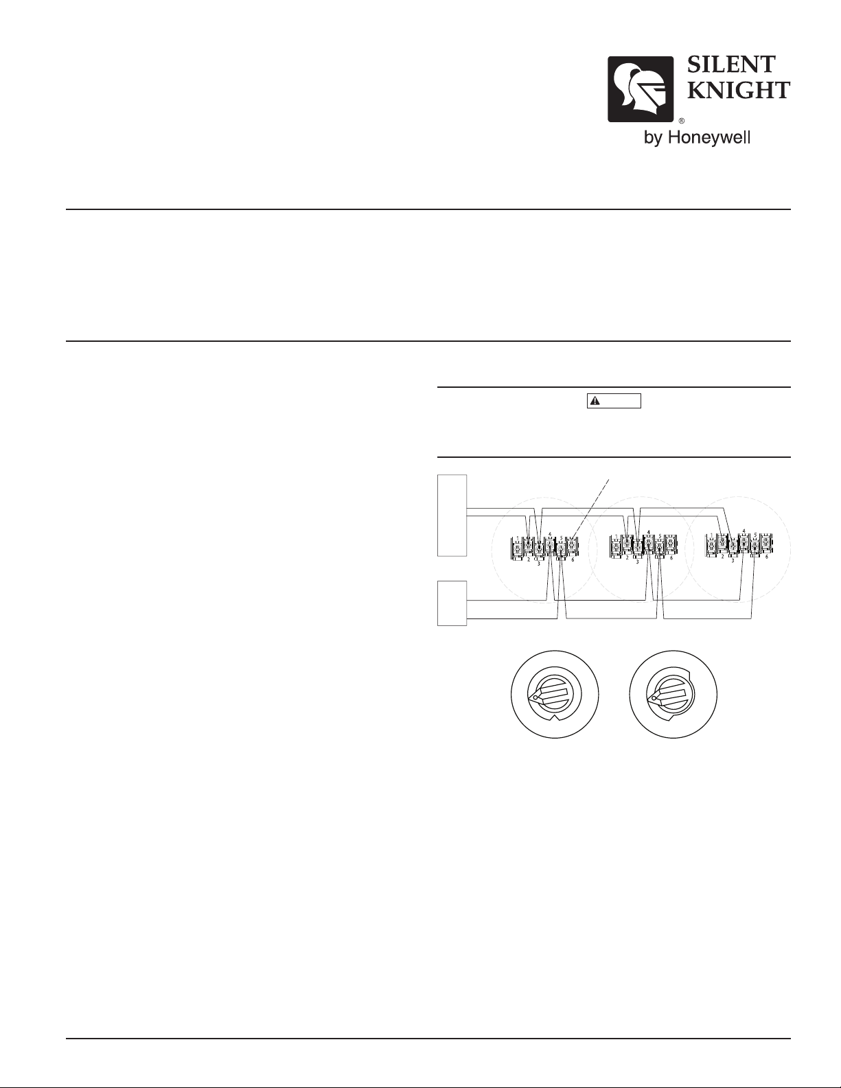
FIGURE 1. WIRING DIAGRAM:
OPTIONAL REMOTE ANNUNCIATOR
Association (NFPA); see NFPA 72 and NFPA 720. For a complete list of compat-
U.L. LISTED COMPATIBLE
(–) COMM.
(+) COMM.
CONTROL PANEL
4
1
5
2
6
3
4
1
5
2
6
3
4
1
5
2
6
3
ible bases, refer to the Base/Sensor Cross Reference Chart at systemsensor.com.
GENERAL DESCRIPTION
Model SK-FIRE-CO is a plug-in type smoke sensor that is a photoelectronic
sensing chamber combined with carbon monoxide (CO), thermal and infra-red
(IR) sensors as well as a carbon monoxide detector both with addressable-analog communications. The sensors transmit an analog representation of smoke
and/or carbon monoxide density over a communication line to a control panel.
Rotary-decade switches are provided for setting the sensor’s address.
Two LEDs on the sensor are controlled by the panel to indicate sensor status.
An output is provided for connection to an optional remote LED annunciator
(P/N RA400Z /RA100Z).
The SK-FIRE-CO requires compatible addressable communications to function properly. Connect these sensors to listed-compatible control panels only.
SPACING
Silent Knight recommends spacing sensors in compliance with NFPA 72. In
low air flow applications with smooth ceilings, space sensors 30 feet apart.
For specific information regarding sensor spacing, placement, and special applications, refer to NFPA 72 or the System Smoke Detector Application Guide,
available from Silent Knight.
TAMPER-RESISTANCE
Model SK-FIRE-CO includes a tamper-resistant capability that prevents removal from the bracket without the use of a tool. Refer to the base manual for
details on making use of this capability.
WIRING GUIDE
All wiring must be installed in compliance with the National Electrical Code,
applicable local codes, and any special requirements of the Authority Having
Jurisdiction. Proper wire gauges should be used. The installation wires should
be color-coded to limit wiring mistakes and ease system troubleshooting. Improper connections will prevent a system from responding properly in the
event of a fire.
Remove power from the communication line before installing sensors.
1. Wire the sensor base (supplied separately) per the wiring diagram, see
Figure 1.
2. Set the desired address on the sensor address switches, see Figure 2.
3. Install the sensor into the sensor base. Push the sensor into the base
while turning it clockwise to secure it in place.
(+) POWER
(–) POWER
EXTERNAL
24V SUPPLY
C0474-02
FIGURE 2. ROTARY DECADE ADDRESS SWITCHES:
9
6
5
4
3
2
1
10
11
12
13
14
15
0
6
5
9
4
3
2
1
0
C0162-00
SMOKE SENSOR TESTING
Before testing, notify the proper authorities that the system is undergoing
maintenance, and will temporarily be out of service. Disable the system to
prevent unwanted alarms.
All sensors must be tested after installation and periodically thereafter. Testing
methods must satisfy the Authority Having Jurisdiction (AHJ). Sensors offer maximum performance when tested and maintained in compliance with NFPA 72.
The sensor can be tested in the following ways:
A. Functional: Magnet Test (P/N M02-04-01 or M02-09-00)
This sensor can be functionally tested with a test magnet. The test mag-
net electronically simulates smoke in the sensing chamber, testing the
sensor electronics and connections to the control panel.
1. Hold the test magnet in the magnet test area as shown in Figure 3.
2. The sensor should alarm the panel.
Two LEDs on the sensor are controlled by the panel to indicate sensor
status. Coded signals, transmitted from the panel, can cause the LEDs
to blink, latch on, or latch off. Refer to the control panel technical documentation for sensor LED status operation and expected delay to alarm.
SK-400-011 1 I56-3945-001
Page 2

CAUTION
SENSOR COVER
TABS
FIGURE 3. TEST MAGNET POSITION:
TEST
MAGNET
B. Smoke Entry:
For SK-FIRE-CO, smoke entry testing should be performed immediately
following the magnet test. Magnet test initiates an approximately 10 minute period when the detector’s signal processing software routines are
not active. Failure to first perform the magnet test will introduce a time
delay before the detector alarms.
Aerosol Generator (Gemini 501) The GEMINI model 501 aerosol genera-
tor can be used for smoke entry testing. Set the generator to represent
4%/ft to 5%/ft obscuration as described in the GEMINI 501 manual. Using the bowl shaped applicator, apply aerosol until the panel alarms.
Canned Aerosol Simulated Smoke. Additionally, canned aerosol simu-
lated smoke (canned smoke agent) may be used for smoke entry testing
of the smoke detector. Tested and approved aerosol smoke products are:
MANUFACTURER MODEL
Home Safeguard Industries 25S
SDi CHEK02 and CHEK06
SDi SOLOA4
SDi SMOKESABRE-01
When used properly, the canned smoke agent will cause the smoke de-
tector to go into alarm. Refer to the manufacturer’s published instructions for proper use of the canned smoke agent.
Canned aerosol simulated smoke (canned smoke agent) formulas will vary by
manufacturer. Misuse or overuse of these products may have long term adverse
effects on the smoke detector. Consult the canned smoke agent manufacturer’s
published instructions for any further warnings or caution statements.
C. Direct Heat Method (Hair Dryer of 1000-1500 watts)
A hair dryer of 1000-1500 watts should be used to test the thermistors. Di-
rect the heat toward either of the two thermistors, holding the heat source
approximately 12 inches from the detector in order to avoid damaging
the plastic housing. The detector will reset only after it has had sufficient
time to cool. Make sure both thermistors are tested individually.
D. Multi-Criteria Testing
Testifire® by SDi provides testing of the smoke, heat and CO sensors. Consult
the manufacturer’s published instructions for complete usage instructions.
A sensor that fails any of these tests should be cleaned as described under
CLEANING, and retested. If the sensor fails after cleaning, it must be replaced.
When testing is complete, restore the system to normal operation and notify
the proper authorities that the system is back in operation.
FUNCTIONAL GAS TEST
NOTE: Check with local codes and the AHJ to determine whether or not a
functional gas test is desired for an installation.
A canned CO testing agent may be used to verify the detector’s ability to
sense CO. Tested and approved canned CO testing agent is solo detector testers model C6 CO Detector Tester available from SDi. Initiate the CO testing
feature of the detector as follows:
C0951-00
FIGURE 4. CO TESTING:
SPRAY AEROSOL
CO HERE INTO
TOP RING
COVER
REMOVAL
C0952-01
1. Put the device into test mode by holding a test magnet in the magnet test
area as shown in Figure 3 for 6-12 seconds.
NOTE: If the magnet is held in place for too long the fire alarm test function
will be triggered. Reset the panel and proceed with testing the CO portion of
the device. It may be preferred to put the device into fire alarm first via the
magnet test to ensure the device has successfully entered test mode.
2. Spray a UL approved CO agent into the top ring of the detector’s gas entry ports within 1/4” of the detector for at least 1 second (see Figure 4). It
is recommended to use the applicator straw included with the CO agent
to more efficiently direct the CO into the detection cell during testing.
3. The detector will go into alarm if gas entry is successful. It may take up
to 1 minute for the device to alarm. Once the detector is in alarm allow 5
minutes for the CO to clear and exit the detector.
The dector will automatically enable the signal processing after 10 minutes.
Testing the detector will activate the alarm relay and send a signal to the panel.
CAUTION: This carbon monoxide detector is designed for indoor use only.
Do not expose to rain or moisture. Do not knock or drop the detector. The
detector will not protect against the risk of carbon monoxide poisoning if not
properly wired. The detector will only indicate the presence of carbon monoxide gas at the sensor. Carbon monoxide gas may be present in other areas.
This carbon monoxide detector is NOT:
• Designed to detect any gas other than carbon monoxide
• To be seen as a substitute for the proper servicing of fuel-burning appliances or the sweeping of chimneys.
• To be used on an intermittent basis, or as a portable alarm for the spillage of combustion products from fuel-burning appliances or chimneys.
Carbon monoxide gas is a highly poisonous gas which is released when fuels
are burnt. It is invisible, has no smell and is therefore impossible to detect with
the human senses. Under normal conditions in a room where fuel burning
appliances are well maintained and correctly ventilated, the amount of carbon
monoxide released into the room by appliances should not be dangerous.
Symptoms of carbon monoxide poisoning: Carbon monoxide bonds to the
hemoglobin in the blood and reduces the amount of oxygen being circulated
in the body. The following symptoms are examples taken from NFPA 720.
They represent approximate values for healthy adults:
Concentration (ppm CO) Symptoms
200 Mild headache after 2-3 hours
of exposure
400 Headache and nausea after
1-2 hours of exposure
800 headache, nausea, and dizziness
after 45 minutes of exposure;
collapse and unconsciousness after
2 hours of exposure
Many causes of reported carbon monoxide poisoning indicate that while victims are aware that they are not well, they become so disoriented that they
are unable to save themselves by either exiting the building or calling for assistance. Also, young children and pets may be the first to be affected.
SK-400-011 2 I56-3945-001
Page 3

SENSOR COVER
DETECTOR BASE
ALARM THRESHOLDS ARE AS FOLLOWS:
Parts Per Million Detector response time, min.
70 ±5ppm 60-240
150 ±5ppm 10-50
400 ±10ppm 4-15
Per UL standard 2075, the SK-FIRE-CO has been tested to the sensitivity limits
defined in UL standard 2034.
What to do if the carbon monoxide detector goes into alarm:
Immediately move to a spot where fresh air is available, preferably outdoors.
IMPORTANT: This detector should be tested and maintained regularly following National Fire Protection Association (NFPA) 720 requirements.
CLEANING
Before removing the detector, notify the proper authorities that the smoke
detector system is undergoing maintenance and will be temporarily out of
service. Disable the zone or system undergoing maintenance to prevent unwanted alarms.
1. Remove the sensor to be cleaned from the system.
2. Remove the sensor cover. Use a small flat blade screwdriver to gently release each of the four cover removal tabs that hold the cover place. Use
caution to avoid damaging the thermistors and other sensors (see Figure 5).
3. Carefully vacuum the outside of the anti insect screen without removing
it from the detector cover.
4. The chamber cover, CO and IR sensors may be removed as a single assembly. Gently pull the assembly away from the sensing chamber being
careful neither to damage the thermistors, the IR / CO sensor PCB nor to
strain the connector cable to the PCB, then gently folded away from the
optical chamber.
5. Use a vacuum cleaner and/or clean compressed air to remove dust and
debris from the sensing chamber and sensing chamber cover.
6. Re-install the sensing chamber cover assembly by sliding the cover over
the chamber, gently pressing it home until it snaps into place.
7. Re-install the sensor cover. Use the cover removal tabs, LEDs and thermistors to align the cover with the sensor. Snap the cover into place.
8. When all sensors have been cleaned and re-installed, restore power to
the loop and test the sensor(s) as described under TESTING.
After completion of maintenance and testing, notify the proper authorities
that the system is operational.
FIGURE 5. SENSOR ASSEMBLY:
IR
SENSOR
COVER
REMOVAL
TABS
CO
SENSOR
OPTICAL
CHAMBER
COVER
THERMISTORS
OPTICAL
CHAMBER
BASE
C0952-00
CO SENSOR LIFETIME
The CO cell has an expected lifetime of approximately six years. The detector is programmed to signal the approach of end of this lifetime to the control panel. The CO cell is not a field replaceable component and on failure,
you should contact the system supplier to arrange for replacement of the cell.
The smoke sensor will continue to operate using the photoelectric sensing
chamber, thermal and infra-red sensors even though the CO cell is no longer
operational. The CO detector will not operate once the CO cell has reached
its end of life.
SPECIAL NOTE REGARDING SMOKE DETECTOR GUARDS
Smoke detectors are not to be used with detector guards unless the combination has been evaluated and found suitable for that purpose.
SK-400-011 3 I56-3945-001
Page 4

Please refer to insert for the Limitations of Fire Alarm Systems
This device complies with part 15 of the FCC Rules. Operation is subject to the following two conditions: (1) This device may not cause harmful interference, and (2) this device must
accept any interference received, including interference that may cause undesired operation.
NOTE: This equipment has been tested and found to comply with the limits for a Class B digital device, pursuant to Part 15 of the FCC Rules. These limits are designed to provide
reasonable protection against harmful interference in a residential installation. This equipment generates, uses and can radiate radio frequency energy and, if not installed and used
in accordance with the instructions, may cause harmful interference to radio communications. However, there is no guarantee that interference will not occur in a particular installation. If this equipment does cause harmful interference to radio or television reception, which can be determined by turning the equipment off and on, the user is encouraged to try
to correct the interference by one or more of the following measures:
– Reorient or relocate the receiving antenna.
– Increase the separation between the equipment and receiver.
– Connect the equipment into an outlet on a circuit different from that to which the receiver is connected.
– Consult the dealer or an experienced radio/TV technician for help.
FCC STATEMENT
SK-400-011 4 I56-3945-001
©2013 Honeywell International Inc.
 Loading...