

Page 1

INTELLIKNIGHT
MODEL 5808
Addressable Fire Control Panel
Installation and
Operation Manual
Part Number 151274 D, 06/03
Page 2

Content
Section 1
Introduction .............................................................................................................................................. 1-1
1.1 Overview of Basic System ....................................................................................................................... 1-1
1.1.1 Hardware Features ............................................................................................................................ 1-1
1.1.2 Software Features ............................................................................................................................. 1-2
1.2 About this Manual .................................................................................................................................... 1-2
1.2.1 Terms Used in this Manual ............................................................................................................... 1-2
1.3 Compatible Products ................................................................................................................................ 1-3
1.4 How to Contact Silent Knight .................................................................................................................. 1-4
Section 2
Agency Listings, Approvals, and Requirements ................................... 2-1
2.1 Federal Communications Commission (FCC) ......................................................................................... 2-1
2.2 Underwriters Laboratories (UL) .............................................................................................................. 2-2
2.2.1 Requirements for All Installations .................................................................................................... 2-2
2.2.2 Requirements for Central Station Fire Alarm Systems .................................................................... 2-2
2.2.3 Requirements for Local Protected Fire Alarm Systems ................................................................... 2-2
2.2.4 Requirements for Remote Station Protected Fire Alarm Systems - Digital Alarm Communicator
Transmitter (DACT) ......................................................................................................................... 2-2
Section 3
Before You Begin Installing ............................................................................................... 3-1
3.1 Whatís in the Box? ................................................................................................................................... 3-1
3.2 Environmental Specifications .................................................................................................................. 3-1
3.3 Electrical Specifications ........................................................................................................................... 3-2
3.4 Wiring Specifications ............................................................................................................................... 3-3
3.5 Board Assembly Diagram ........................................................................................................................ 3-4
3.6 Calculating Current Draw and Standby Battery ...................................................................................... 3-5
3.6.1 Worksheet Requirements .................................................................................................................. 3-5
3.6.2 Current Draw Worksheet .................................................................................................................. 3-6
3.6.2.1 Maximum Battery Standby Load ........................................................................................... 3-8
Section 4
Control Panel Installation ...................................................................................................... 4-1
4.1 Mounting the Control Panel Cabinet ....................................................................................................... 4-1
4.1.1 Removing the 5808 Assembly from the Housing ............................................................................. 4-1
4.2 AC Connection ......................................................................................................................................... 4-2
4.3 Battery Connection .................................................................................................................................. 4-3
4.3.1 RBB Accessory Cabinet ................................................................................................................... 4-4
4.3.1.1 Installing the RBB Accessory Cabinet and Batteries ............................................................. 4-4
151274 i
Page 3

4.4 SBUS Wiring ........................................................................................................................................... 4-6
4.4.1 Calculating Wiring distance for SBUS modules ..............................................................................4-6
4.4.2 Wiring Configurations ...................................................................................................................... 4-9
4.5 Remote Annunciator 5860 Installation .................................................................................................. 4-10
4.5.1 Mounting the 5860 .......................................................................................................................... 4-11
4.5.1.1 Flush Mounting .................................................................................................................... 4-12
4.5.1.2 Surface Mounting ................................................................................................................. 4-14
4.5.2 Model 5860 Connection to the Panel .............................................................................................. 4-14
4.6 5824 Serial/Parallel Interface Installation .............................................................................................. 4-15
4.6.1 Selecting 5824 Options ................................................................................................................... 4-16
4.7 5880 LED Driver Module ...................................................................................................................... 4-18
4.7.1 5880 Board Layout ......................................................................................................................... 4-18
4.7.2 FACP Connection ........................................................................................................................... 4-19
4.7.3 LED Wiring .................................................................................................................................... 4-20
4.7.4 Dry Contact Wiring ........................................................................................................................ 4-21
4.8 5865-3 / 5865-4 LED Annunciator Installation ..................................................................................... 4-22
4.8.1 FACP Connection ........................................................................................................................... 4-23
4.8.2 5865 Mounting ................................................................................................................................ 4-23
4.9 Configuring Modules ............................................................................................................................. 4-25
4.9.1 Assigning Module IDs .................................................................................................................... 4-25
4.10 Telephone Connection ........................................................................................................................... 4-26
4.11 Notification Appliance/Auxiliary Power Circuits .................................................................................. 4-27
4.11.1 Conventional Notification Appliance ............................................................................................. 4-27
4.11.1.1 Class B Notification Wiring ................................................................................................. 4-27
4.11.1.2 Class A Notification Wiring ................................................................................................ 4-28
4.11.2 Auxiliary Power Installation ........................................................................................................... 4-29
4.11.2.1 Door Holder Power .............................................................................................................. 4-29
4.11.2.2 Constant Power .................................................................................................................... 4-30
4.11.2.3 Resettable Power .................................................................................................................. 4-30
4.12 On-Board Relays (Conventional) ........................................................................................................... 4-30
4.12.1 Trouble Relay ................................................................................................................................. 4-30
4.12.2 Programmable Relays ..................................................................................................................... 4-30
4.13 Remote Station Applications ................................................................................................................. 4-31
4.13.1 Keltron Model 3158 Installation ..................................................................................................... 4-31
4.13.2 City Box Connection Using the 5220 Module ................................................................................4-32
4.13.3 NFPA 72 Polarity Reversal ............................................................................................................. 4-33
4.13.3.1 Using the 5220 Module ........................................................................................................ 4-33
4.13.4 Using the SD500-ARM Addressable Relay Module ...................................................................... 4-35
4.13.5 Using a MR-201/T Control Relay From Air Products ................................................................... 4-36
Section 5
SLC Device Installation ............................................................................................................ 5-1
5.1 Types of SLC Devices ............................................................................................................................. 5-1
5.2 Maximum Number of Devices ................................................................................................................. 5-2
5.3 Wiring Requirements for SLC Devices ................................................................................................... 5-2
5.3.1 Wiring SLC devices in Style 4 (Class B) ......................................................................................... 5-2
5.3.2 Wiring SLC Devices in Style 6 & 7 (Class A) ................................................................................. 5-4
5.4 Heat and Smoke Detector Installation ..................................................................................................... 5-5
5.4.1 Wiring ............................................................................................................................................... 5-5
5.5 Duct Detector Installation ........................................................................................................................ 5-6
5.6 Input Monitor Module (SD500-AIM) ...................................................................................................... 5-7
151274 ii
Page 4

5.7 Mini Input Module (SD500-MIM) .......................................................................................................... 5-8
5.8 Relay Module Installation ........................................................................................................................ 5-9
5.8.1 Electrical Specifications ................................................................................................................... 5-9
5.8.2 Wiring ............................................................................................................................................... 5-9
5.9 SLC Device Addressing ......................................................................................................................... 5-10
5.9.1 EEPROM Addressing ..................................................................................................................... 5-10
5.9.2 Dipswitch Addressing ..................................................................................................................... 5-11
Section 6
Programming Overview ........................................................................................................... 6-1
6.1 JumpStart Autoprogramming ................................................................................................................... 6-1
6.1.1 Input Points ....................................................................................................................................... 6-2
6.1.2 Output Points .................................................................................................................................... 6-2
6.1.3 Running JumpStart ........................................................................................................................... 6-2
6.2 Mapping Overview .................................................................................................................................. 6-4
6.2.1 Input Point Mapping ......................................................................................................................... 6-5
6.2.2 Output Circuit Mapping .................................................................................................................... 6-6
6.2.3 Zone Event Mapping ........................................................................................................................ 6-7
6.2.4 Mapping LED Points ........................................................................................................................ 6-9
6.3 Silent Knight Software Suite (SKSS) .................................................................................................... 6-10
6.4 Annunciator Programming ..................................................................................................................... 6-10
6.4.1 Entering / Exiting the Program Menu ............................................................................................. 6-11
6.4.2 Moving through the Menus ............................................................................................................. 6-12
6.4.3 Selecting Options and Entering Data .............................................................................................. 6-12
6.4.4 Editing Keys ................................................................................................................................... 6-13
6.5 Programming Menu Quick Reference ................................................................................................... 6-14
Section 7
Programming ......................................................................................................................................... 7-1
7.1 Modules .................................................................................................................................................... 7-1
7.1.1 Edit Modules .....................................................................................................................................7-1
7.1.1.1 Naming Modules .................................................................................................................... 7-2
7.1.1.2 Module, Wiring Class ............................................................................................................ 7-2
7.1.2 Adding a Module .............................................................................................................................. 7-2
7.1.3 Deleting a Module ............................................................................................................................ 7-3
7.2 Zone ......................................................................................................................................................... 7-4
7.2.1 Edit Zone ........................................................................................................................................... 7-4
7.2.1.1 Edit Zone Name ..................................................................................................................... 7-4
7.2.1.2 Edit Zone Properties ............................................................................................................... 7-5
7.2.1.3 Zone Outputs .......................................................................................................................... 7-7
7.2.1.4 Cadence Patterns .................................................................................................................. 7-10
7.2.2 Add Zone ........................................................................................................................................ 7-11
7.2.3 Delete Zone ..................................................................................................................................... 7-11
7.2.4 View Zone Points ............................................................................................................................ 7-12
7.3 Group ..................................................................................................................................................... 7-13
7.3.1 Edit Group ....................................................................................................................................... 7-13
7.3.1.1 Edit Group Name ................................................................................................................. 7-13
7.3.1.2 Edit Group Properties ........................................................................................................... 7-14
7.3.2 Add Group ...................................................................................................................................... 7-16
151274 iii
Page 5

7.3.3 Delete Group ................................................................................................................................... 7-16
7.3.4 View Group Points .......................................................................................................................... 7-17
7.3.5 Edit Output Group Templates ......................................................................................................... 7-18
7.4 Point ....................................................................................................................................................... 7-19
7.4.1 Point Programming For SLC .......................................................................................................... 7-19
7.4.2 Point Programming For Internal
or External Power Module (5496) .................................................................................................. 7-22
7.4.3 Point Programming For 5880 and 5865 Modules ........................................................................... 7-23
7.4.3.1 Assigning a Name to a Points .............................................................................................. 7-24
7.5 System Options ...................................................................................................................................... 7-26
7.5.1 Reporting Account .......................................................................................................................... 7-26
7.5.1.1 Edit Accounts ....................................................................................................................... 7-27
7.5.1.2 Auto Test Time .................................................................................................................... 7-30
7.5.2 Phone Lines ..................................................................................................................................... 7-30
7.5.2.1 Dialing Prefix ....................................................................................................................... 7-31
7.5.2.2 Number of Answer Rings .................................................................................................... 7-31
7.5.2.3 Dial Option (TouchTone or Pulse) ....................................................................................... 7-32
7.5.2.4 Rotary Format ...................................................................................................................... 7-32
7.5.2.5 Line Monitor ........................................................................................................................ 7-32
7.5.2.6 Ground Start Relay ............................................................................................................... 7-32
7.5.2.7 Answering Machine Bypass ................................................................................................. 7-33
7.5.3 Sys. Event Outputs .......................................................................................................................... 7-33
7.5.3.1 Trouble Events ..................................................................................................................... 7-33
7.5.3.2 System Alarm Cadence ........................................................................................................ 7-34
7.5.4 Miscellaneous Options .................................................................................................................... 7-35
7.5.4.1 Water Flow Delay ................................................................................................................ 7-35
7.5.4.2 Low AC Report Delay .........................................................................................................7-36
7.5.4.3 Automatic Daylight Savings Adjustment ............................................................................ 7-36
7.5.4.4 Clock Display Format (AM/PM or Military) ....................................................................... 7-36
7.5.4.5 Change AC Line Frequency ................................................................................................. 7-36
7.5.5 Miscellaneous Options 2 ................................................................................................................. 7-37
7.5.5.1 Synchronize Strobes Active During Silence ........................................................................ 7-37
7.5.5.2 Auto Display Oldest Event .................................................................................................. 7-37
7.5.5.3 Report by Zone or by Point .................................................................................................. 7-37
7.5.6 Edit Banner Message ...................................................................................................................... 7-38
7.6 JumpStart Autoprogramming ................................................................................................................. 7-39
7.7 Computer Account ................................................................................................................................. 7-40
7.8 Access Codes ......................................................................................................................................... 7-41
7.8.1 Profile Edit Menu ............................................................................................................................ 7-42
7.8.1.1 Edit Name ............................................................................................................................ 7-42
7.8.1.2 Edit Access Code ................................................................................................................. 7-42
7.8.1.3 Panel Functions .................................................................................................................... 7-43
Section 8
System Operation ............................................................................................................................ 8-1
8.1 Annunciator Description .......................................................................................................................... 8-1
8.1.1 LCD Displays ................................................................................................................................... 8-2
8.1.2 Banner ............................................................................................................................................... 8-2
8.2 Key Operation .......................................................................................................................................... 8-2
8.3 Menu System ............................................................................................................................................ 8-3
8.3.1 Main Menu Overview ....................................................................................................................... 8-3
151274 iv
Page 6

8.3.2 Using the Menus ............................................................................................................................... 8-4
8.4 Basic Operation ........................................................................................................................................ 8-4
8.4.1 Setting Time and Date ...................................................................................................................... 8-4
8.4.2 Disable / Enable a Point .................................................................................................................... 8-4
8.4.3 View Event History .......................................................................................................................... 8-4
8.4.3.1 To clear the event history ....................................................................................................... 8-5
8.4.4 Conduct a Fire Drill .......................................................................................................................... 8-5
8.4.5 Conduct an Indicator Test ................................................................................................................. 8-5
8.4.6 Conduct a Walk Test ......................................................................................................................... 8-6
8.4.7 Conduct a Dialer Test ....................................................................................................................... 8-6
8.4.8 Silence alarms or troubles ................................................................................................................. 8-6
8.4.9 Reset alarms ...................................................................................................................................... 8-7
8.4.10 Check Detector Through Point Status .............................................................................................. 8-7
8.4.11 View Status of a Point ...................................................................................................................... 8-8
8.4.12 View Alarms or Troubles ................................................................................................................. 8-8
8.4.13 View System Information ................................................................................................................. 8-8
8.4.14 Reset dialer ....................................................................................................................................... 8-8
8.4.15 Communicating with a Remote Computer ....................................................................................... 8-9
8.4.16 Working with a Printer ................................................................................................................... 8-10
8.5 Operation Mode Behavior ...................................................................................................................... 8-11
8.6 Releasing Operations ............................................................................................................................. 8-14
8.6.1 Single Interlock Zone Releasing ..................................................................................................... 8-15
8.6.2 Double Interlock Zone Releasing ................................................................................................... 8-16
Section 9
Reporting ..................................................................................................................................................... 9-1
9.1 Receivers Compatible with the Control Panel ......................................................................................... 9-1
Section 10
Installation Records .................................................................................................................... 10-1
10.1 SLC Point Record .................................................................................................................................. 10-1
Section 11
Testing and Troubleshooting ......................................................................................... 11-1
11.1 Troubleshooting ..................................................................................................................................... 11-1
11.2 Common Problems ................................................................................................................................. 11-1
11.2.1 Event History .................................................................................................................................. 11-2
11.3 Built-in Troubleshooting and Testing Tools .......................................................................................... 11-3
11.3.1 SLC Device Locator ....................................................................................................................... 11-3
11.3.2 SLC Multi Locator .......................................................................................................................... 11-4
11.3.3 I/O Point Control ............................................................................................................................ 11-5
151274 v
Page 7

Appendix A
Compatible Devices ..................................................................................................................... A-1
A.1 Notification Appliances .......................................................................................................................... A-1
A.2 Door Holder Device ................................................................................................................................ A-9
Appendix B
Special Characters Lists .........................................................................................................B-1
B.1 Characters used for Naming .....................................................................................................................B-1
151274 vi
Page 8

Section 1
Introduction
The 5808 Fire Alarm Control / Communicator is an addressable fire control system that meets
the requirements of UL 864.
1.1 Overview of Basic System
The 5808 base system is 127 addressable point sytem with a built-in annunciator which can
also be used to program the system.
1.1.1 Hardware Features
ï The 5808 panel contains one SLC (Signaling Line Circuit) which supports 127
addressable devices (points).
ï 6.0A of output power is available through 4 sets of terminals for notification appliance
circuits or auxiliary applications. Each circuit is power limited per UL 864 and can source
up to 3.0A (total output power for all 4 circuits must not exceed 6.0A).
ï Built-in dual phone line, digital alarm communicator/transmitter (DACT).
ï Reports events to central station by point or by zone.
ï UL Listed for pre-action and deluge releasing systems.
ï Two general purpose Form C programmable relays.
ï One Form C Trouble Relay.
ï Basic system operation can be performed using a key or a user code.
ï Can be used with up to 8 Model 5860 Remote Annunciators (sold separately).
ï Can be used with Model 5865-3, 5865-4, and 5880 in any combination for a total of eight
devices on one control panel. See Sections 4.7 and 4.8 for additional information on these
models.
ï Printing of detector status, event history, and real time event log available through the
Model 5824 Serial / Parallel Interface (sold separately).
ï 125 software zones, 125 output groups.
ï Add 4 Notification/Auxiliary power circuits with each 5496 Intelligent Power Module (up
to 8, 5496s per system).
151274 1-1
Page 9

Model 5808 Installation and Operation Manual
1.1.2 Software Features
ï Advanced smoke detector features:
ñAutomatic drift compensation
ñMaintenance alert region
ñPoint status eliminates calibrated smoke test requirements for NFPA 72
ï ì JumpStartî feature for easy programming
ï Non-volatile event history stores 1000 events
ï A choice of output patterns available for notification outputs, including ANSI 3.41
temporal signal
ï Built-in synchronization appliance support for AMSECO, Faraday, GentexÆ, or
WheelockÆ.
1.2 About this Manual
This manual is intended to be a complete reference for all installation and operation tasks for
the 5808. Please let us know if the manual does not meet your needs in any way. We value
your feedback!
1.2.1 Terms Used in this Manual
The following terminology is used with the 5808 system:
Term Description
SLC Signaling Line Circuit
Module The term module is used for all hardware devices except for
SLC addressable devices and notification appliances. This
includes the 5808 panel itself.
Input Point An addressable sensing device, such as a smoke or heat detector
or a contact monitor device.
Input Zone A protected area made up of input points.
Output Point
(or Output Circuit)
Group (or ì Output Groupî ) A group of output points. Operating characteristics are common
Output (or ì Cadenceî ) Pattern The pattern that the output will use, for example, Constant,
Mapping Mapping is the process of specifying which outputs are
A notification point or circuit for notification appliances. Relay
circuits and auxiliary power circuits are also considered output
points.
to all output points in the group.
March Code, ANSI 3.41. Applies to zones and special system
events. See Section 7.5.3.2 for additional information.
activated when certain events occur in the system. Section 6.2
explains mapping in detail.
1-2 151274
Page 10

Introduction
1.3 Compatible Products
The chart below lists the products available from Silent Knight for use with the 5808.
Type of
Device
SLC Devices
Other
Modules
Model Description
SD500-AIM Contact Monitor Module (switch input). Standard size. (This device replaces Model
SD500-FRCM-4. See Note below.)
SD500-ARM Relay Module (This device replaces Model SD505-ARM. See Note below.)
SD500-MIM Mini Contact Monitor Module (switch input). Small size. (This device replaces
Model SD500-FRCM. See Note below.)
SD500-PS Addressable pull station
SD500-LED The SD500-LED is a LED driver module capable of driving 80 LEDs which connects
to the SLC loop on a Silent Knight addressable control panel.
Up to 40 SD500-LED modules can be used on the SLC loop.
SD500-LIM Short circuit isolator module for SLC devices.
SD505-6IB Short circuit isolator base for SD505-AHS, SD505-APS, and SD505-AIS detectors.
SD505-AHS Heat Sensor
SD505-AIS Ionization Smoke Detector
SD505-APS Photoelectric Smoke Detector
SD505-ADH
Duct housing is shipped
with a detector base only.
Detector head must be
ordered separately.
SD505-ADHR Duct detector housing with relay module. Compatible with the same peripheral
SD505-DTS Optional remote test station compatible with the SD505-ADHR.
5211 Ground Start Relay For use with ground start telephone network. (Do not use in UL installations.)
5824 Serial/Parallel
Interface
5496 Intelligent Power
Module
5860 and 5860R Remote
Fire Alarm Annunciator
5860TG and 5860TR Trim
Ring Kit
5865-3 and 5865-4 LED
Annunciator
5880 LED Driver Module Driver for up to 40 LEDs. Interfaces with customized annunciator boards. In addition
5883 General Purpose
Relay Module
7860 Telephone Cord RJ31X cord for connecting phone line to the 5808.
Duct Housing for use with SD505-AIS ionization smoke detector or SD505-APS
photoelectric smoke detector head.
Intake tubing for duct available in 3 lengths:
STS-2.5: Duct widths 1.0í to 2.5í
STS-5.0: Duct widths 2.5í to 5.0í
STS-10.0: Duct widths 5.0í to 10.0í
When ordering SD505-ADH, specify intake tubing size and order the appropriate
smoke detector, if needed.
devices as the SD505-ADH.
Allows a printer to be attached for the system for on-site event logging, detector
status and event history reports. Two maximum per system.
Provides 4 additional Notification Appliance Circuits/Auxiliary power. (Up to 8 per
5808 system.)
Same operation, similar appearance as on-board annunciator. Up to 8 5860s per
system. 5860 is gray; 5860R is red.
Trim ring kits for surface mounting the 5860 annunciator. 5860TG is gray; 5860TR is
red.
LED annunciator can display up to 30 LEDs (15 red and 15 yellow). 5865-4 has key
switches for silence and reset, and a system trouble LED.
the 5880 has eight generic switch input points.
Provides 10 Form C relays. Designed to be driven by the 5880. Up to four, 5883s can
be used with each 5880 module.
151274 1-3
Page 11

Model 5808 Installation and Operation Manual
Type of
Device
Software
Misc.
Silent Knight Software
Suite (SKSS) 5660
SKSS Facility
Management Software
5670
7628 UL Listed End-of-line resistor
RBB Remote Battery Box used when your backup batteries requirements use backup
Model Description
For communication and panel programming with a Windows-based computer and
*modem (not sold by Silent Knight, see Table 1-1 for compatible modems). Enables
remote viewing of detector status and event history.
For remote viewing of detector status and event history. Requires a modem (not sold
by Silent Knight).
batteries that are too large to fit into the main control panel cabinet.
Note: 5865-3, 5865-4, and 5880 can be used in any combination, up to a total of eight devices on one panel.
The following modems have been tested by Silent Knight for compatibility with the 5808 and
the Silent Knight Software Suite software packages:
Table 1-1: Compatible Modems
Manufacturer Model
US Robotics 28.8
LifeStyle
Motorola
MultiTech MT19321ZDX
28.8, 3400 series
Premier 33.6
1.4 How to Contact Silent Knight
If you have a question or encounter a problem not covered in this manual, contact Silent
Knight Technical Support at 800-328-0103 (or 763-493-6455). To order parts, contact Silent
Knight Sales at 800-446-6444 (or 763-493-6435).
1-4 151274
Page 12

Introduction
Limitations of Fire Alarm Systems
Manufacturer recommends that smoke and/or heat detectors be located throughout a protected
premise following the recommendations of the current edition of the National Fire Protection
Association Standard 72 (NFPA 72
), manufacturerís recommendations, State and local codes,
and the recommendations contained in Guide for the Proper Use of System Smoke Detectors
which is made available at no charge to all installing dealers. A study by the Federal
Emergency Management Agency (an agency of the United States government) indicated that
smoke detectors may not go off or give early warning in as many as 35% of all fires. While
fire alarm systems are designed to provide warning against fire, they do not guarantee warning
or protection against fire. A fire alarm system may not provide timely or adequate warning, or
simply may not function, for a variety of reasons. For example:
ï Particles of combustion or smoke from a developing fire may not reach the sensing
chambers of smoke detectors because:
Barriers such as closed or partially closed doors, walls, or chimneys may inhibit particle or
smoke flow.
Smoke particles may become cold, stratify, and not reach the ceiling or upper walls where
detectors are located.
,
Smoke particles may be blown away from detectors by air outlets
Smoke particles may be drawn into air returns before reaching the detector.
In general, smoke detectors on one level of a structure cannot be expected to sense fires
developing on another level.
ï The amount of smoke present may be insufficient to alarm smoke detectors. Smoke
detectors are designed to alarm at various levels of smoke density. If such density levels
are not created by a developing fire at the location of detectors, the detectors will not go
into alarm.
ï Smoke detectors, even when working properly, have sensing limitations. Detectors that
have photoelectronic sensing chambers tend to detect smoldering fires better than flaming
fires, which have little visible smoke. Detectors that have ionizing-type sensing chambers
tend to detect fast flaming fires better than smoldering fires. Because fires develop in
different ways and are often unpredictable in their growth, neither type of detector is
necessarily best and a given type of detector may not provide adequate warning of a fire.
ï Smoke detectors are subject to false alarms and nuisance alarms and may have been
disconnected by users. For example, a smoke detector located in or near a kitchen may go
into nuisance alarm during normal operation of kitchen appliances. In addition, dusty or
steamy environments may cause a smoke detector to falsely alarm. If the location of a
smoke detector causes an abundance of false alarms or nuisance alarms, do not disconnect
the smoke detector; call a professional to analyze the situation and recommend a solution.
ï Smoke detectors cannot be expected to provide adequate warning of fires caused by arson,
children playing with matches (especially within bedrooms), smoking in bed, violent
explosions (caused by escaping gas, improper storage of flammable materials, etc.).
ï Heat detectors do not sense particles of combustion and are designed to alarm only when
heat on their sensors increases at a predetermined rate or reaches a predetermined level.
Heat detectors are designed to protect property, not life.
151274 1-5
Page 13

Model 5808 Installation and Operation Manual
ï Warning devices (including horns, sirens, and bells) may not alert people or wake up
sleepers who are located on the other side of closed or partially open doors. A warning
device that activates on a different floor or level of a dwelling or structure is less likely to
awaken or alert people. Even persons who are awake may not notice the warning if the
alarm is muffled by noise from a stereo, radio, air conditioner or other appliance, or by
passing traffic. Audible warning devices may not alert the hearing-impaired (strobes or
other devices should be provided to warn these people). Any warning device may fail to
alert people with a disability, deep sleepers, people who have recently used alcohol or
drugs, or people on medication or sleeping pills.
Please note that:
i) Strobes can, under certain circumstances, cause seizures in people with conditions
such as epilepsy.
ii) Studies have shown that certain people, even when they hear a fire alarm signal, do not
respond or comprehend the meaning of the signal. It is the property ownerís responsibility to conduct fire drills and other training exercises to make people aware of fire
alarm signals and instruct on the proper reaction to alarm signals.
iii) In rare instances, the sounding of a warning device can cause temporary or permanent
hearing loss.
ï Telephone lines needed to transmit alarm signals from a premises to a central station may
be out of service or temporarily out of service. For added protection against telephone line
failure, backup radio transmission systems are recommended.
ï System components, though designed to last many years, can fail at any time. As a
precautionary measure, it is recommended that smoke detectors be checked, maintained,
and replaced per manufacturerís recommendations.
ï System components will not work without electrical power. If system batteries are not
serviced or replaced regularly, they may not provide battery backup when AC power fails.
ï Environments with high air velocity or that are dusty or dirty require more frequent
maintenance.
In general, fire alarm systems and devices will not work without power and will not function
properly unless they are maintained and tested regularly.
While installing a fire alarm system may make the owner eligible for a lower insurance rate,
an alarm system is not a substitute for insurance.
Property owners should continue to act
prudently in protecting the premises and the people in their premises and should properly
insure life and property and buy sufficient amounts of liability insurance to meet their needs.
1-6 151274
Page 14

Introduction
Requirements and recommendations for proper use of fire alarm systems including smoke detectors and other fire alarm devices:
Early fire detection is best achieved by the installation and maintenance of fire detection
equipment in all rooms and areas of the house or building in accordance with the requirements
and recommendations of the current edition of the National Fire Protection Association
Standard 72, National Fire Alarm Code (NFPA 72), the manufacturerís recommendations,
State and local codes and the recommendations contained in Guide for the Proper Use of
System Smoke Detectors, which is made available at no charge to all installing dealers. For
specific requirements, check with the local Authority Having Jurisdiction (ex. Fire Chief) for
fire protection systems.
Requirements and Recommendations include:
ï Smoke Detectors shall be installed in sleeping rooms in new construction and it is
recommended that they shall also be installed in sleeping rooms in existing construction.
ï It is recommended that more than one smoke detector shall be installed in a hallway if it is
more than 30 feet long.
ï It is recommended that there shall never be less then two smoke detectors per apartment or
residence.
ï It is recommended that smoke detectors be located in any room where an alarm control is
located, or in any room where alarm control connections to an AC source or phone lines
are made. If detectors are not so located, a fire within the room could prevent the control
from reporting a fire.
ï All fire alarm systems require notification devices, including sirens, bells, horns, and/or
strobes. In residential applications, each automatic alarm initiating device when activated
shall cause the operation of an alarm notification device that shall be clearly audible in all
bedrooms over ambient or background noise levels (at least 15dB above noise) with all
intervening doors closed.
ï It is recommended that a smoke detector with an integral sounder (smoke alarm) be
located in every bedroom and an additional notification device be located on each level of
a residence.
ï To keep your fire alarm system in excellent working order, ongoing maintenance is
required per the manufacturerís recommendations and UL and NFPA standards. At a
minimum the requirements of Chapter 7 of NFPA 72 shall be followed. A maintenance
agreement should be arranged through the local manufacturerís representative.
Maintenance should be performed annually by authorized personnel only.
ï The most common cause of an alarm system not functioning when a fire occurs is
inadequate maintenance. As such, the alarm system should be tested weekly to make sure
all sensors and transmitters are working properly.
151274 1-7
Page 15

Model 5808 Installation and Operation Manual
1-8 151274
Page 16

Section 2
Agency Listings, Approvals, and Requirements
2.1 Federal Communications Commission (FCC)
1. The following information must be provided to the telephone company before the 5808
can be connected to the phone lines:
Table 2-1
A Manufacturer: Silent Knight
B Model Number: 5808
C FCC registration number: AC6 USA-34758-AL-E
Ringer equivalence: 0.8B
D Type of jack: RJ31X
E Facility Interface Codes: Loop Start: 02LS2
Ground Start: 02GS2
F Service Order Code: 9.0F
2. This device may not be directly connected to coin telephone or party line services.
3. This device cannot be adjusted or repaired in the field. In case of trouble with the device,
notify the installing company or return to:
Silent Knight
7550 Meridian Circle
Maple Grove, MN 55369-4927
763-493-6455
800-328-0103
4. If the 5808 causes harm to the telephone network, the telephone company will notify the
user in advance that temporary discontinuance of service may be required. If advance
notice is not practical, the telephone company will notify the user as soon as possible.
Users have the right to file complaints, if necessary, with the Federal Communications
Commission.
5. The telephone company may make changes in its facilities, equipment, operations, or pro-
cedures that could affect the operation of the equipment. If this happens, the telephone
company will provide advance notice to allow you to make the necessary modifications to
maintain uninterrupted service.
Warning
This device has been verified to comply with FCC Rules Part 15. Operation is subject to the following conditions:
(1) This device may not cause radio interference, and (2) This device must accept any interference received,
including interference that may cause undesired operation.
151274 2-1
Page 17

Model 5808 Installation and Operation Manual
2.2 Underwriters Laboratories (UL)
2.2.1 Requirements for All Installations
General requirements are described in this section. When installing an individual device,
refer to the specific section of the manual for additional requirements. The following
subsections list specific requirements for each type of installation (for example, Central
Station Fire Alarm systems, Local Protected Fire Alarm systems, and so on). See Section 8.6
for information on releasing operation.
1. All field wiring must be installed in accordance with NFPA 70 National Electric Code.
2. Use the addressable smoke detectors specified in Section 5.1 of this manual.
3. Use UL listed notification appliances compatible with the 5808 from those specified in the
Appendix at the back of this manual.
4. A full system checkout must be performed any time the panel is programmed.
2.2.2 Requirements for Central Station Fire Alarm
Systems
1. Use both phone lines. Enable phone line monitors for both lines.
2. You must program a phone number and a test time so that the 5808 sends an automatic
daily test to the central station.
3. Do not use the ground start option.
4. The AC Loss Hours option must be set from 6-12 hours.
5. The Attempts to Report option must be set for 5.
2.2.3 Requirements for Local Protected Fire Alarm
Systems
At least one UL listed supervised notification appliance must be used.
2.2.4 Requirements for Remote Station Protected Fire
Alarm Systems - Digital Alarm Communicator
Transmitter (DACT)
1. Do not exceed the current load restrictions shown in Section 3.6.2.1.
2. The AC Loss Hours option must be set from 15-30 hours.
2-2 151274
Page 18

Section 3
Before You Begin Installing
This section of the manual is intended to help you plan your tasks to facilitate a smooth
installation. Please read this section thoroughly, especially if you are installing a 5808 panel
for the first time.
3.1 Whatís in the Box?
The 5808 ships with the following hardware:
ï A cabinet with all hardware assembled
ï Two keys for the front door
ï Two keys for user operation of the on-board annunciator (installer operations require the
Installerís Code)
ï Ten 4.7K ohm end-of-line resistors
ï A battery cable for batteries wired in series
3.2 Environmental Specifications
It is important to protect the 5808 control panel from water. To prevent water damage, the
following conditions should be AVOIDED when installing the units:
ï Do not mount directly on exterior walls, especially masonry walls (condensation)
ï Do not mount directly on exterior walls below grade (condensation)
ï Protect from plumbing leaks
ï Protect from splash caused by sprinkler system inspection ports
ï Do not mount in areas with humidity-generating equipment (such as dryers, production
machinery)
When selecting a location to mount the 5808 control panel, the unit should be mounted where
it will NOT be exposed to temperatures outside the range of 0∞C-49∞C (32∞F-120∞F) or
humidity outside the range of 10%-85% at 30∞C (86∞F) noncondensing.
151274 3-1
Page 19

Model 5808 Installation and Operation Manual
3.3 Electrical Specifications
Table 3-1 list the terminal block on the 5808 as well as a description of the each individual
terminal and their respective electrical rating. For location of the terminals refer to Figure 3-2.
Table 3-1: Terminal Descriptions and Electrical Specifications
Terminal No.
Terminal Block 1 AC INPUT
Terminal Block 2
Terminal Block 3
Terminal Block 4
Terminal Block 5
Group Individual Voltage Current
SLC IN
SLC OUT
SLC PROG
TELCO 1
PHONE 1
TELCO 2
PHONE 2
TROUBLE
RELAY 1
RELAY 2
NAC1
NAC2
NAC3
NAC4
SBUS
BATTERY
Label
B AC input (hot) 120 VAC, 60 Hz 2.75 A
Earth Earth Ground N/A N/A
W AC input (neutral) 120 VAC, 60 Hz 2.75 A
ñ
+
ñ
+
ñ
+
RING Phone Line 1 Telco Ring
TIP Phone Line 1 Telco Tip
RING Phone Line 1 Phone Ring
TIP Phone Line 1 Phone Tip
RING Phone Line 2 Telco Ring
TIP Phone Line 2 Telco Tip
RING Phone Line 2 Phone Ring
TIP Phone Line 2 Phone Tip
NC Normally closed relay contact
NO Normally open relay contact
NC Normally closed relay contact
NO Normally open relay contact
NC Normally closed relay contact
NO Normally open relay contact
ñ
+
ñ
+
ñ
+
ñ
+
B
A
+
ñ
+ To Positive battery terminal
ñ To Negative battery terminal
Used for Class A installations 32 VDC 150 mA
SLC terminals 32 VDC 150 mA
Used for programming SLC
Detectors
Notification Appliance
Circuit/Auxiliary power
Notification Appliance
Circuit/Auxiliary power
Notification Appliance
Circuit/Auxiliary power
Notification Appliance
Circuit/Auxiliary power
SBUS Communication 5 VDC 100 mA
SBUS Power 24 VDC 1.0 A
Description
Rating
32 VDC 150 mA
24 VDC 2.5 A, resistiveCOM Common terminal
24 VDC 2.5 A, resistiveCOM Common terminal
24 VDC 2.5 A, resistiveCOM Common terminal
24 VDC
24 VDC
24 VDC
24 VDC
24 VDC
3.0 Amp NAC or Aux
power
3.0 Amp NAC or Aux
power
3.0 Amp NAC or Aux
power
3.0 Amp NAC or Aux
power
Up to 33 Ah (see Section
4.3 for details)
3-2 151274
Page 20
Before You Begin Installing
3.4 Wiring Specifications
Induced noise (transfer of electrical energy from one wire to another) can interfere with
telephone communication or cause false alarms. To avoid induced noise, follow these
guidelines:
ï Isolate input wiring from high current output and power wiring. Do not pull one multi-
conductor cable for the entire panel. Instead, separate the wiring as follows:
High voltage AC power Terminals
SLC loops
Audio input/output Phone line circuits
Notification circuits NAC1 through NAC4
SBUS
Relay circuits
ï Do not pull wires from different groups through the same conduit. If you must run them
together, do so for as short a distance as possible or use shielded cable. Connect the shield
to earth ground at the panel. You must route high and low voltages separately.
ï Route the wiring around the inside perimeter of the cabinet. It should not cross the circuit
board where it could induce noise into the sensitive microelectronics or pick up unwanted
RF noise from the high speed circuits. See Figure 3-1 for an example.
ï High frequency noise, such as that produced by the inductive reactance of a speaker or
bell, can also be reduced by running the wire through ferrite shield beads or by wrapping it
around a ferrite toroid.
Phone Lines
SLC IN/OUT
AC Power
Input
1/4" spacing must be
maintained between each
of these circuit types; as well
as between power limited
and non-power limited circuits.
Relay Outputs
NAC/Aux Power
Outputs
SBUS Devices
151274 3-3
Figure 3-1 Wire Routing Example
Page 21
Model 5808 Installation and Operation Manual
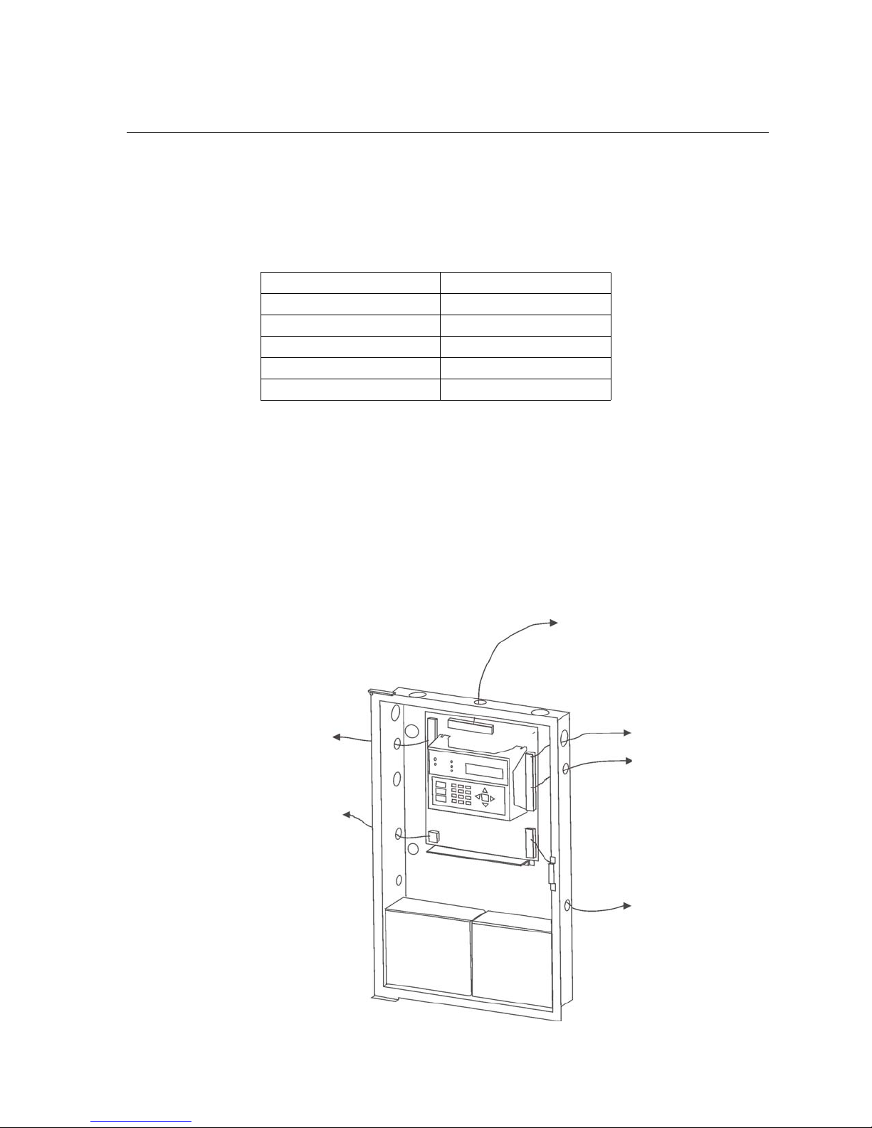
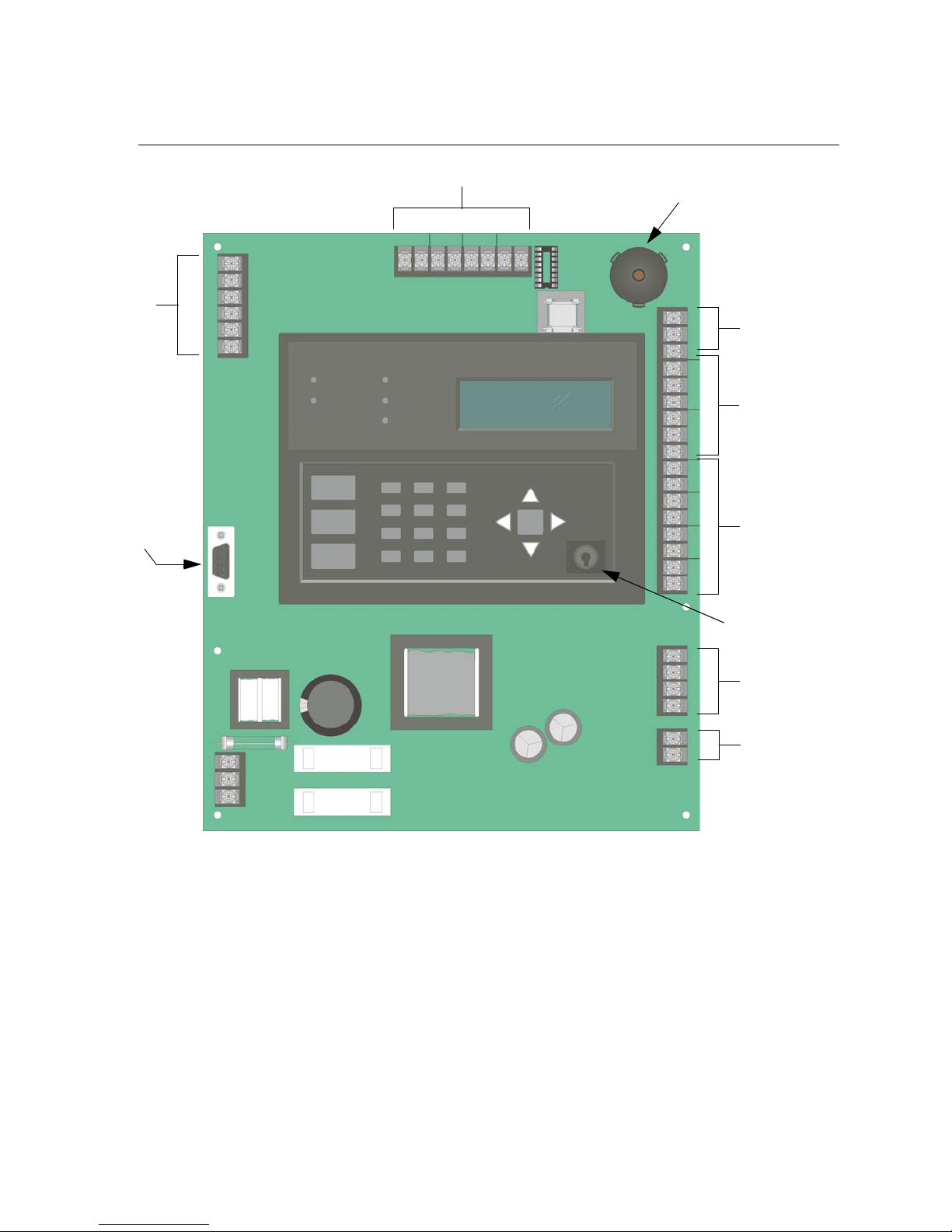
3.5 Board Assembly Diagram
SLC
In/Out
Programming
Port
Phone lines
On-board
Annunciator
Form C
Trouble
Relay
Form C
Relays
NAC/Aux
Power Circuits
Key Switch
Input
SBUS
Connections
Battery
Connections
AC Power
Input
Figure 3-2 Model 5808 Assembly
Figure 3-2 shows the circuit boards, and annunciator. If you should need to remove the control
board for repair, remove the nine mounting screws (six on the circuit board and 3 on the heatsink) which hold the control board in the cabinet. Then lift the control board out of the
cabinet.
3-4 151274
Page 22

3.6 Calculating Current Draw and Standby Battery
This section is for helping you determine the current draw and standby battery needs for your
installation.
3.6.1 Worksheet Requirements
The following steps must be taken when determining 5808 current draw and standby battery
requirements.
Filling in the Current Draw Worksheet, Table 3-2 (Section 3.6.2)
1. For the 5808, the worst case current draw is listed for the panel, addressable devices, and
all SBUS expanders. Fill in the number of addressable devices that will be used in the system and compute the current draw requirements for alarm and standby. Record this information in Table 3-2 at Line A.
2. Add up the current draw for all auxiliary devices and record in the table at Line B.
3. Add up all notification appliance loads and record in the table at Line C.
4. For notification appliance circuits and auxiliary devices not mentioned in the manual,
refer to the device manual for the current ratings.
5. Make sure that the total alarm current you calculated, including current for the panel itself,
does not exceed 6.0 A. This is the maximum alarm current for the 5808 control panel.
If the current is above 6.0 A you will need to use a notification power expander(s) such as
the Silent Knight 5496 intelligent power module, to distribute the power loads so that the
5808 or the power expanders do not exceed their power rating. Refer to the current draw
worksheets provided with the 5496 manual so you do not exceed their power requirements.
6. Complete the remaining instructions in Table 3-2 for determining battery size require-
ments.
151274 3-5
Page 23

Model 5808 Installation and Operation Manual
3.6.2 Current Draw Worksheet
Use Table 3-2 to determine current requirements during alarm/battery standby operation.
(Copy the page if additional space is required.)
Table 3-2: Current Draw Worksheet
Device # of Devices Current per Device
For each device use this formula: This column X This column = Current per number of devices.
5808 Fire Panel (Current draw
from battery)
Addressable SLC Devices
SD500-AIM
SD500-MIM mA mA
SD500-PS
SD500-ARM mA mA
SD505-AHS mA mA
SD505-AIS mA mA
SD505-APS mA mA
SD500-LED (40 max.)
SD505-ADHR (127 max.)
SD505-DTS (127 max.) Alarm: ***75 mA
SD505-ADH (127 max.) None, included with detector current.
SLC Isolator Devices
SD505-LIM (254 max.)
SD505-6IB (127 max.)
Accessories Modules
5860 Remote Fire Alarm
Annunciator
5824 Serial / Parallel Module (2 max.) Standby/Alarm: 45 mA mA mA
5496 Notification Power Expander (8 max.) Standby/Alarm: 10 mA mA mA
5865-4 LED Annunciator
(with reset and silence switches)
5865-3 LED Annunciator
5880 Generic LED Driver Module
1
(127 max.) Standby/Alarm: 0.55 mA
(8 max.)
(8 max.)
Standby: 206 mA 206 mA
Alarm: 356 mA 356 mA
Standby: 10 mA mA
Aux. Pwr
SLC
Aux. Pwr
SLC
Standby/Alarm 0.092 mA mA mA
Standby: 20 mA mA
Alarm: 25 mA mA
Standby: 35 mA mA
Alarm: 145 mA mA
Standby: 35 mA mA
Alarm: 145 mA mA
Standby: 35 mA mA
Alarm: 200 mA mA
Alarm: 220 mA mA
LED: 10 mA mA mA
Standby/
Alarm: 0.55 mA
Standby: ***35 mA mA
Alarm: ***75 mA mA
Standby/
Alarm: .082 mA
Standby
Current
mA mA
mA mA
mA mA
Alarm
Current
3-6 151274
Page 24

Table 3-2: Current Draw Worksheet
Before You Begin Installing
Device # of Devices Current per Device
Standby: 0 mA mA
5883 Relay Interface (32 max.)
A Total System Current
*Auxiliary Devices Refer to devices manual for current rating.
B Auxiliary Devices Current
Notification Appliance Ciruits Refer to devices manual for current rating.
C Notification Appliances Current
D Total current ratings of all devices in system (line A + line B + C) mA mA
E Total current ratings converted to amperes (line D x .001): A A
F Number of standby hours (24 or 60 for NFPA 72, chapter 1, 1-5.2.5): H
G Multiply lines E and F. Total standby AH AH
H Alarm sounding period in hours. (For example, 5 minutes = .0833 hours) H
I Multiply lines E and H. Tota l a la r m AH
J
**Add lines G and I.
Alarm: 220 mA
(22 mA per relay)
Alarm/Standby: mA mA mA
Alarm/Standby: mA mA mA
Alarm/Standby: mA mA mA
Alarm/Standby: mA mA mA
Alarm: mA mA
Alarm: mA
Alarm: mA mA
Alarm: mA mA
Total ampere hours
required
Standby
Current
AH
Alarm
Current
mA
mA
mA
AH
* If you are using door holders, you do not need to consider door holder current for alarm/battery standby,
because power is removed during that time. However, during normal operation, door holders draw current
and must be included in the 6.0 A total current that can be drawn from the panel.
** Use next size battery with capacity greater than required.
*** If using Aux power only. No standby or alarm current for battery calculation if using 24 VAC, 120 VAC or
240 VAC.
151274 3-7
Page 25

Model 5808 Installation and Operation Manual
3.6.2.1 Maximum Battery Standby Load
The table below shows the maximum battery standby load for the 5808 based on 24 and 60
hours of standby. The standby load calculations of line D in the Current Draw Calculation
Worksheet (Table 3-2) must be less than the number shown in the table below for the battery
size used and standby hours required.
Rechargeable Battery Size
7 AH 221 mA 85 mA
12 AH 475 mA 190 mA
18 AH 685 mA 270 mA
33 AH 1.1 A 450 mA
* Required for NFPA 72 Auxiliary Protected Fire Alarm systems for Fire Alarm Service (City Box) and Remote
Station Protected Fire Alarm systems (Polarity Reversal) and Digital Alarm Communicator/Transmitter
(DACT).
Max. Load for 24 hrs.
Standby, 5 mins. Alarm
*Max. Load for 60 hrs.
Standby, 5 mins. Alarm
Warning!
Silent Knight does not support the use of batteries smaller than those listed in table above. If you use a battery
too small for the installation, the system could overload the battery resulting in the installation having less than
the required 24 hours standby power. Use Table 3-2 to calculate the correct battery amperes/hour rating needed
for your installation.
3-8 151274
Page 26

Section 4
Control Panel Installation
Caution!
To avoid the risk of electrical shock and damage to the unit, power should be OFF at the control panel while
installing or servicing.
4.1 Mounting the Control Panel Cabinet
Read the environmental specifications in Section 3.2 before mounting the 5808 panel.
The 5808 cabinet dimensions are:
16" W x 26.4" H x 3.5" D (40.64 cm W x 67.06 cm H x 8.89 cm D).
The 5808 panel should be located within a secured area, where it is accessible to main drop
wiring runs and where it can be easily tested and serviced. End-users responsible for
maintaining the panel should be able to hear alarms and troubles. When selecting a location,
keep in mind that the panel itself is the main source of alarm and trouble annunciation.
When mounting on interior walls, use appropriate screw anchors in plaster. When mounting
on concrete, especially when moisture is expected, attach a piece of 3/4 inch plywood to the
concrete surface and then attach the 5808 to the plywood. Also mount any other desired
components to the plywood.
DO NOT flush-mount the 5808 cabinet in a wall designated as a fire break.
4.1.1 Removing the 5808 Assembly from the Housing
If it should ever be necessary to remove the control panel assembly from the cabinet for
repair, do so by removing the screws that hold the control panel in to the cabinet. Do not
attempt to disassemble the circuit boards.
151274 4-1
Page 27
Model 5808 Installation and Operation Manual
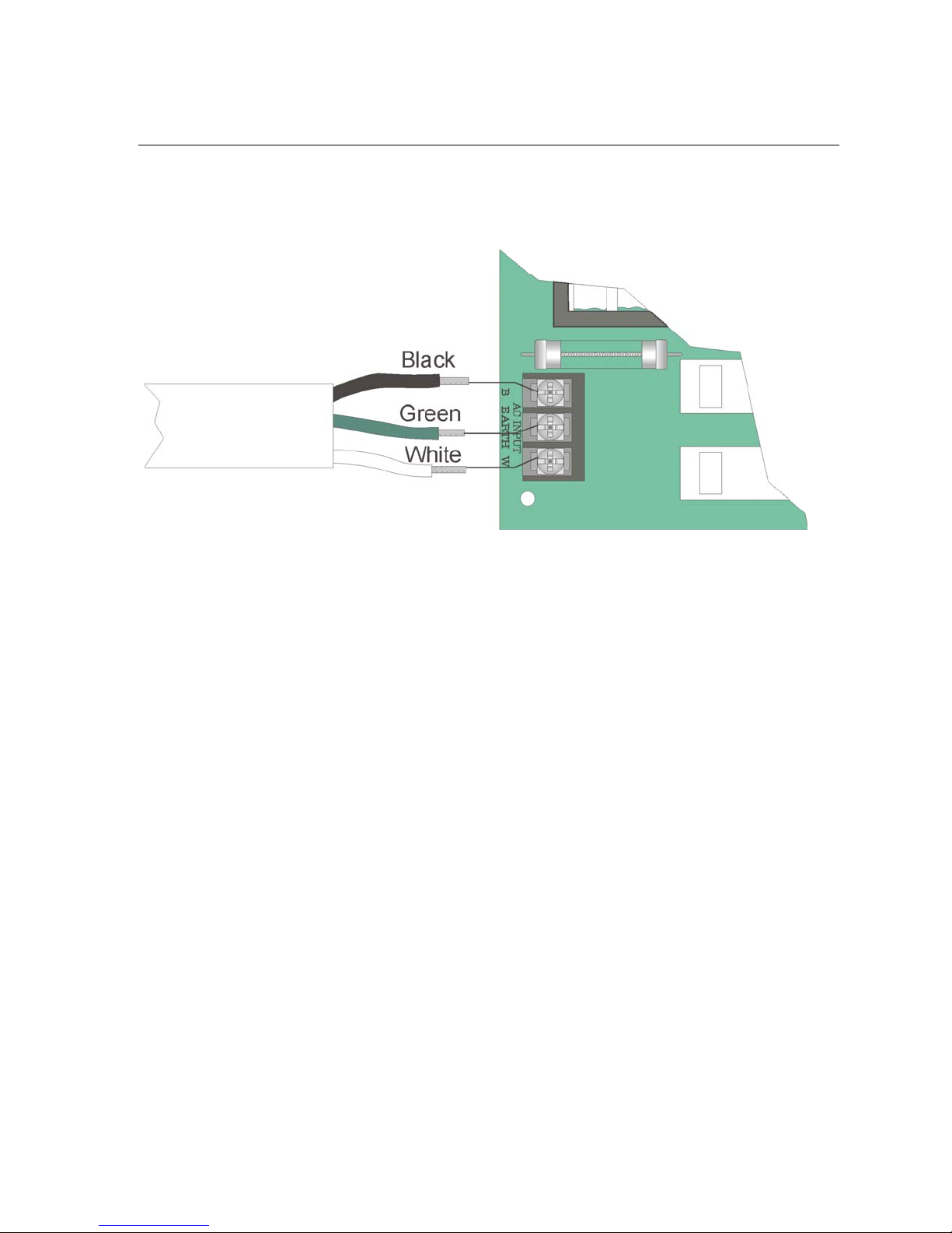
4.2 AC Connection
At installation, connect the AC terminals to the power source as shown in Figure 4-1. It may
be necessary for a professional electrician to make this connection.
The AC terminals are rated at 120 VAC, 60 Hz, 2.5A .
Figure 4-1 120VAC Power Connection
4-2 151274
Page 28
Control Panel Installation
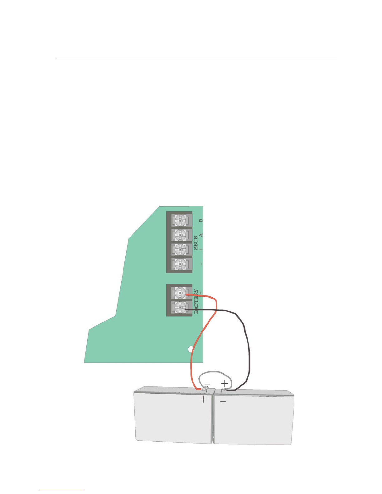
4.3 Battery Connection
The control panel battery charge capacity is 7.0 to 33.0 AH. The main control cabinet can
house batteries up to 18 AH, larger capacity batteries can be housed in a RBB (see Section
4.3.1 for deteails).Use 12V batteries of the same AH rating. Determine the correct AH rating
as per your current load calculation (see Section 3.6).
Wire batteries in series to produce a 24-volt equivalent. Do not parallel batteries to increase
the AH rating.
The following steps and diagram explain how to connect the batteries.
1. Connect the black wire from the control panel negative (ñ) battery terminal to the negative
(ñ) side of Battery #2.
2. Connect the jumper wire provided (P/N 140694) from the positive (+) side of Battery #2
to the (ñ) negative side of Battery #1.
3. Connect the red wire from the control panel positive (+) terminal to the positive (+) side of
Battery #1.
Red
Black
Battery Jumper
(P/N 140694)
Shipped With Panel
UL Listed 12V Battery
Battery 1
Figure 4-2 Battery Connection
151274 4-3
UL Listed 12V Battery
Battery 2
Page 29
Model 5808 Installation and Operation Manual
4.3.1 RBB Accessory Cabinet
The Model RBB Accessory cabinet can be used when your backup batteries requirements use
backup batteries that are too large to fit into the main control panel cabinet. The RBB cabinet
holds batteries up to the 33 AH size. The RBB dimensions are 16" W x 10" H x 6" D (40.64
cm W x 25.4 cm H x 15.24 cm D).
4.3.1.1 Installing the RBB Accessory Cabinet and Batteries
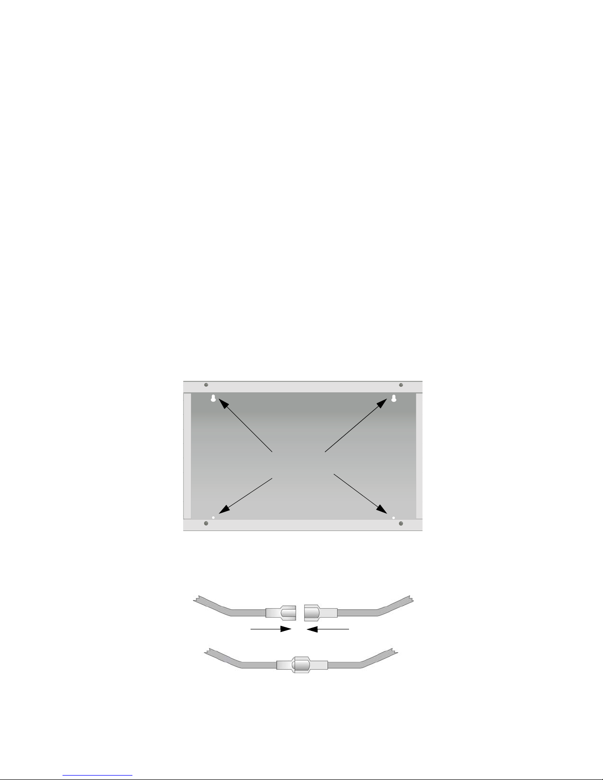
To properly install the accessory cabinet and backup batteries, follow these steps:
1. Mount the accessory cabinet. See figure Figure 4-3 for the four cabinet mounting holes.
ï If mounting onto drywall the accessory cabinet must be mounted onto 3/4-inch ply-
wood. This is necessary because the weight of the batteries inside the accessory cabinet could cause the cabinet to pull away from the drywall.
ï When mounting on concrete, especially when moisture is expected, attach a piece of
3/4-inch plywood to the concrete surface and then attach the RBB cabinet to the plywood.
ï If using the battery cable extenders provided (P/N 140643), mount the RBB cabinet no
more than 18" away from the main control panel cabinet. This will ensure that the battery cables reach the battery terminals.
Cabinet
Mounting Holes
Figure 4-3 RBB Cabinet Mounting Holes
2. Connect the main control panel battery cables to the battery cable extenders as shown in
Figure 4-4.
Figure 4-4 Splicing Control panel Battery Cable to RBB Battery Cable Extenders
4-4 151274
Page 30
Control Panel Installation
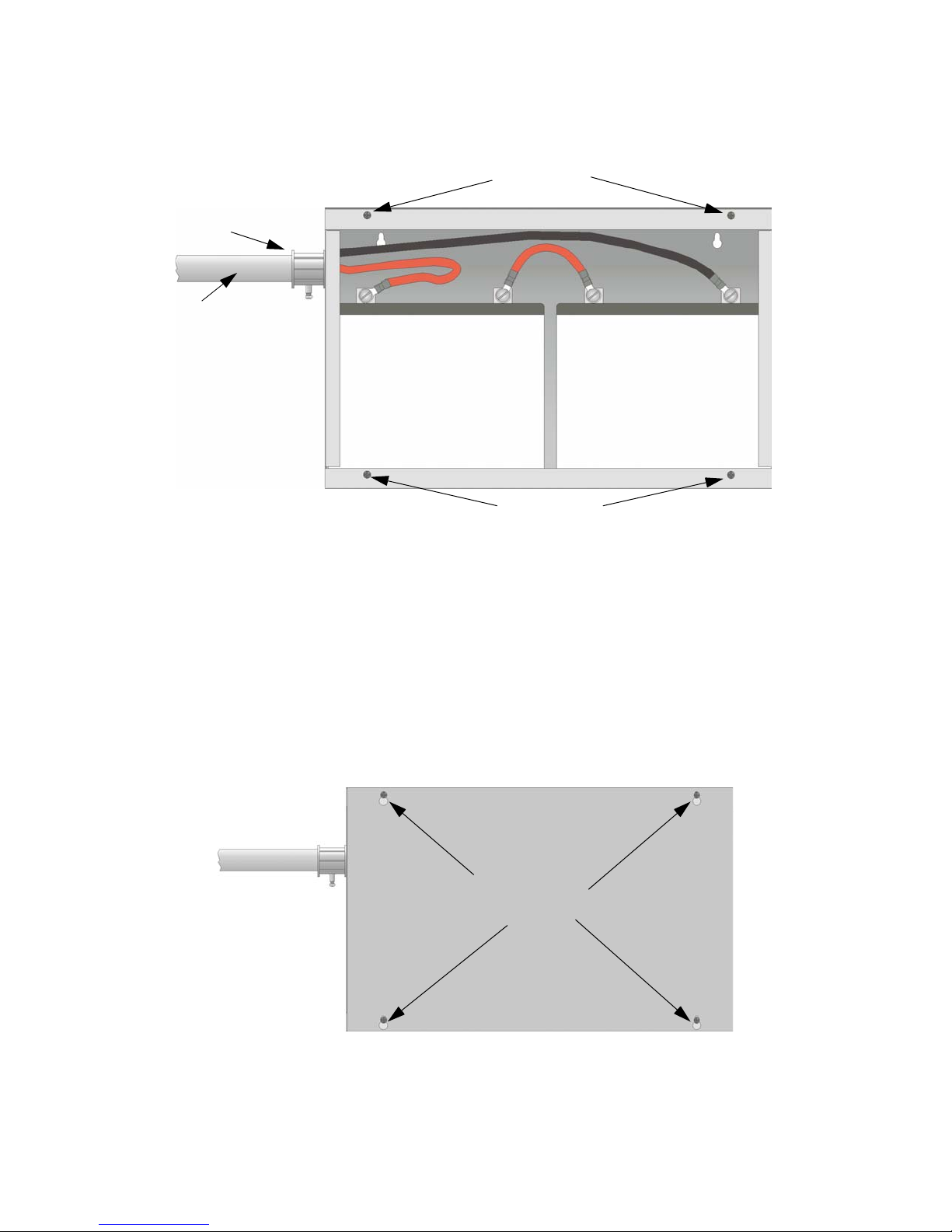
3. Run extended battery cable from control panel cabinet through conduit to RBB cabinet.
See Figure 4-5.
RBB Cabinet
Cover Screws
Conduit
Coupler
Conduit
+
Figure 4-5 Battery Connections in the RBB Cabinet
Note: Figure 4-5 is an example of how the wire connections can be routed. However, any other cabinet knock-
outs (on either the main control panel or the RBB cabinet), that are not previously being used may be utilized to connect conduit between the two cabinets.
-
+
RBB Cabinet
Cover Screws
-
4. Connect battery leads to the backup battery terminals. See Figure 4-5.
Observe the proper polarity to prevent damage to the batteries or the control panel.
5. Insert the RBB cover screws into the cover mounting holes (see Figure 4-5).
Screw the cover screw 3/4 of the way into the cover mounting hole.
6. Align the cover plate mounting keyhole over the cover mounting screws. See Figure 4-6.
Figure 4-6 Cover Plate Mounting Keyholes and Cover Mounting Screws Alignment
7. Slide the cover into place and tighten the cover mounting screws. See Figure 4-6.
151274 4-5
Cover Plate
Mounting Keyholes
Page 31

Model 5808 Installation and Operation Manual
4.4 SBUS Wiring
This section contains information on calculating SBUS wire distances and the types of wiring
configurations (Class B).
4.4.1 Calculating Wiring distance for SBUS modules
The following instructions will guide you in determining the type of wire and the maximum
wiring distance that can be used with control panel SBUS accessory modules.
To calculate the wire gauge that must be used to connect SBUS modules to the control panel,
it is necessary to calculate the total worst case current draw for all modules on a single 4conductor bus. The total worst case current draw is calculated by adding the individual worst
case currents for each module. The individual worst case values are shown in the table below.
Note: Total worst case current draw on a single SBUS cannot exceed 1 amp.
Model Number Worst Case Current Draw
5860 Fire Annunciator .100 amps
5824 Parallel/Serial Interface .040 amps
5880 LED Driver Module .250 amps
5865 LED Fire Annunciator .200 amps
5496 Notification Power Supply .010 amps
After calculating the total worst case current draw, Table 4-1 specifies the maximum distance
the modules can be located from the panel on a single wire run. The table insures 6.0 volts of
line drop maximum. In general, the wire length is limited by resistance, but for heavier wire
gauges, capacitance is the limiting factor.
4-6 151274
Page 32

Control Panel Installation
These cases are marked in the chart with an asterisk (*). Maximum length can never be more
than 6,000 feet, regardless of gauge used. (The formula used to generate this chart is shown in
the note below).
Table 4-1: Wiring Distances
Wiring Distance: SBUS Modules to Panel
Total Worst Case
Current Draw (amps)
0.100 1852 ft. 4688 ft. * 6000 ft. * 6000 ft.
0.200 926 ft. 2344 ft. 3731 ft. 5906 ft.
0.300 617 ft. 1563 ft. 2488 ft. 3937 ft.
0.400 463 ft. 1172 ft. 1866 ft. 2953 ft.
0.500 370 ft. 938 ft. 1493 ft. 2362 ft.
0.600 309 ft. 781 ft. 1244 ft. 1969 ft.
0.700 265 ft. 670 ft. 1066 ft. 1687 ft.
0.800 231 ft. 586 ft. 933 ft. 1476 ft.
0.900 206 ft. 521 ft. 829 ft. 1312 ft.
1.000 (Max) 185 ft. 469 ft. 746 ft. 1181 ft.
22 Gauge 18 Gauge 16 Gauge 14 Gauge
Note: The following formulas were used to generate the wire distance chart:
Maximum Resistance (Ohms) =
Maximum Wire Length (Feet) =
(6000 feet maximum)
where: Rpu = Ohms per 1000 feet for various Wire Gauges (see table below)
Wire Gauge Ohms per 1000 feet (Rpu)
Total Worst Case Current Draw (amps)
Maximum Resistance (Ohms)
22 16.2
18 6.4
16 4.02
14 2.54
6.0 Volts
Rpu
* 500
151274 4-7
Page 33

Model 5808 Installation and Operation Manual
Wiring Distance calculation example:
Suppose a system is configured with the following SBUS modules:
2 - Module 5860 Fire Annunciator
1 - 5496 Notification Power Expander
1 - 5865 LED Fire Annunciator
1 - 5824 Parallel/Serial Interface
The total worst case current is calculated as follows:
5860 Current Draw = 2 x .100 amps = .200 amps
5496 Current Draw = 1 x .010 amps = .010 amps
5865 Current Draw = 1 x .200 amps = .200 amps
5824 Current Draw = 1 x .040 amps = .040 amps
Total Worst Case Current Draw = .450 amps
Using this value, and referring to the Wiring Distance table, it can be found that the available
options are:
370 feet maximum using 22 Gauge wire
938 feet maximum using 18 Gauge wire
1493 feet maximum using 16 Gauge wire
2362 feet maximum using 14 Gauge wire
4-8 151274
Page 34

4.4.2 Wiring Configurations
Figure 4-7 illustrates Class B configuration.
Control Panel Installation
Supervised
Power Limited
Figure 4-7 SBUS Class B Wiring
151274 4-9
Page 35

Model 5808 Installation and Operation Manual
4.5 Remote Annunciator 5860 Installation
The optional Model 5860 Remote Annunciator, shown in Figure 4-8, performs the same
functions as the on-board annunciator. Operation is identical. Up to 8 annunciators can be
added to the 5808 system.
Figure 4-8 Model 5860 Remote Annunciator, Front View
5860 installation involves the following steps:
1. Make sure power is off at the panel.
2. Mount the 5860 in the desired location (see Section 4.5.1).
3. Connect the 5860 to the panel (see Section 4.5.2).
4. Use the dipswitches on the back of the 5860 to assign an ID# to the 5860 (see Section
4.9.1).
5. The new 5860 module must be added to the system through programming. JumpStart will
add the module automatically (see Section 6.1). You can also add it manually (see Section
7.1.2). Select a name, if desired (see Section 7.1.1.1).
4-10 151274
Page 36

Control Panel Installation
4.5.1 Mounting the 5860
This section of the manual describes mounting the remote annunciator. The annunciator can
be flush- or surface-mounted.
Figure 4-9 shows the parts of the annunciator. Instructions for disassembling and mounting
appear on the following pages.
151274 4-11
Figure 4-9 Annunciator Parts
Page 37

Model 5808 Installation and Operation Manual
The 5860 comes from the factory fully assembled. You must disassemble it for mounting. To
disassemble the annunciator, use a 5/64 hex wrench to remove the set screws, located on the
bottom of the annunciator bezel. (See Figure 4-10 for location of the set screws.)
Figure 4-10 Annunciator Back Box and Bezel Details
4.5.1.1 Flush Mounting
This section of the manual describes flush mounting. You can flush-mount with or without an
electrical box.
4-12 151274
Page 38

Control Panel Installation
Flush Mounting with an Electrical Box
The 5860 annunciator can be used with the following types of electrical boxes: 4S, singlegang, and double-gang.
If an electrical box is used, the box must be 1-3/8î back from the face of the wall to
accommodate the annunciator. Studs used with an electrical box must be two by fours (or
larger).
Figure 4-11 Placement of Electrical Box for Flush Mounting
Flush Mounting Steps
1. Cut a hole in the sheet rock to the following dimensions: 8-1/4î w x 6-5/8î h. If an electri-
cal box is used, the box must be 1-3/8î back from face of wall to accommodate the annunciator (see Figure 4-11).
2. Remove knockout holes as needed for wires.
3. Fit the annunciator back box into the hole and stabilize with mounting wires. Angle the
mounting wires into the first hole past the sheet rock. Secure the wires behind the screws
as shown in Figure 4-12. When all four wires are in place, the back box should fit snugly
into the hole in the sheet rock.
151274 4-13
Page 39

Model 5808 Installation and Operation Manual
4. After the annunciator wiring to the panel has been completed (described in Section 4.5.2),
replace the electronic assembly in the back box. Place the bezel over the back box and
tighten the set screws on the bezel.
Figure 4-12 Flush Mounting the Back Box
4.5.1.2 Surface Mounting
The 5860 can be mounted directly to a surface or can be attached to a single, double, or foursquare electrical box. The Model 5860TG/TR trim ring kit is available for use when surface
mounting.
1. Drill holes in the surface to match the screw holes on the back box.
2. Fit the trim ring over the back box.
3. Attach the back box to the surface using screws provided.
4. After the annunciator wiring to the panel has been completed (described in Section 4.5.2),
replace the electronic assembly in the back box. Place the bezel over the back box and
tighten the set screws on the bezel.
4.5.2 Model 5860 Connection to the Panel
Connect the 5860 to the panel as shown in Figure 4-13.
Figure 4-13 Model 5860 Connection to the Panel
4-14 151274
Supervised
Power Limited
Page 40

Control Panel Installation
4.6 5824 Serial/Parallel Interface Installation
The 5824 Serial / Parallel Interface allows you to connect a printer to the panel, so you can
print a real-time log of system events, a report of detector status, and event history.
Instructions for installing the 5824 appear below.
5824 installation involves the following steps:
1. Make sure power is off at the panel.
2. Connect the 5824 to the panel as shown in Figure 4-14.
Note: Two 5824s per panel maximum.
3. Use the dipswitches on the back of the 5824 board to assign an ID# to the 5824 (see Sec-
tion 4.9.1).
4. Configure the 5824 device through programming. See Section 4.6.1.
5. Connect a printer to the 5824 as shown in Figure 4-15.
Supervised
Power Limited
Figure 4-14 5824 Connection to the Panel
151274 4-15
Page 41

Model 5808 Installation and Operation Manual
To Parallel Printer
To Serial Printer
Figure 4-15 Printer Connection
4.6.1 Selecting 5824 Options
Configuring the 5824 includes the following steps:
ï Add the module to the system. JumpStart will add the module automatically (see Section
6.1). You can also add it manually (see Section 4.9).
ï Select a name, if desired (see Section ).
ï Select options for the printer and the output port. See below.
4-16 151274
Page 42

Printer and Output Port Options
Control Panel Installation
1. From the Main Menu, select for Program Menu.
2. Select for Module.
3. Select for Edit Module.
1
1
7
4. From the list that displays, select the 5824 module you want to configure.
5. Press to bypass the next two screens. A screen similar to the one shown in
ENTER ENTER
Figure 4-16 will display.
Figure 4-16 Selecting Printer and Output Port Options
6. Select options for the printer as needed for your installation. Most printers are parallel.
7. If you are using a serial printer, use the next screen to select serial port options as required
for your printer. Refer to your printer manual if you need more information.
Option Choices
Baud Rate: 75 - 19200
Data Bits: 5 - 8
Stop Bits: .5, 1, 2
Parity: None, Even, Odd
151274 4-17
Page 43

Model 5808 Installation and Operation Manual
4.7 5880 LED Driver Module
The 5880 is an LED driver board that can be used in a wide variety of applications, including
as an interface with most customized floor plan annunciator boards. The 5880 can drive up to
40 LEDs and has one PZT controller. The 5880 also has eight inputs for dry contact
monitoring. The following sub-sections describe hardware installation. Refer to Section 6 for
programming information.
4.7.1 5880 Board Layout
Figure 4-17 is a picture of the 5880 board showing locations of screw terminals for connection
to the panel and contact monitor wiring; pin connectors for connecting LEDs; and the
dipswitch for selecting an SBUS ID number.
Dry Contact Inputs - Supervised/Power Limited
SBUS Address
DIPs
SBUS Connection
Figure 4-17 5880 Board Layout
4-18 151274
Page 44

Control Panel Installation
4.7.2 FACP Connection
The 5880 connects to the panel via the SBUS. Make connections as shown in Figure 4-18.
After the 5880 is connected to the panel, it must be added to the system. This programming
step is described in Section 4.9.
Supervised
Power Limited
Figure 4-18 5880 Connection to Main Control Panel Assembly
151274 4-19
Page 45

Model 5808 Installation and Operation Manual
4.7.3 LED Wiring
There are four 12-pin connectors on the 5880 board for connecting LEDs. Each LED gets its
power from Pin 11. Internal resistors are sized so that there is approximately 10 mA of current
for each LED, no series resistors are required. LED outputs can be mapped to output circuits.
See Section 6 for programming details.
Wire the LEDs as shown in Figure 4-19.
On connector P1, Pin 12 is an open collector output for controlling a PZT. If used, the 5880
PZT will match the PZT pattern of the on-board (or 5860) annunciator.
Note: The circuit connected to ì Open Collector Outputî (last pin on P1) must be current limited so that no more
than 100 mA of current is allowed to flow into the open collector transistor.
4-20 151274
Figure 4-19 5880 Board Layout
Page 46

Control Panel Installation
4.7.4 Dry Contact Wiring
The 8 input circuits on the 5880 board are for monitoring switch inputs-any type of switch
supported by the control panel can be used with the 5880. For example, you can use a 5880 to
monitor pull stations, water flow, tamper, reset, or silence switches.
Wire dry contacts as shown in Figure 4-20. Notice grouping of terminals; power terminals are
shared by two inputs.
Supervised
151274 4-21
Model 7628
4.7kΩ EOL
Figure 4-20 Dry Contact Wiring
Page 47
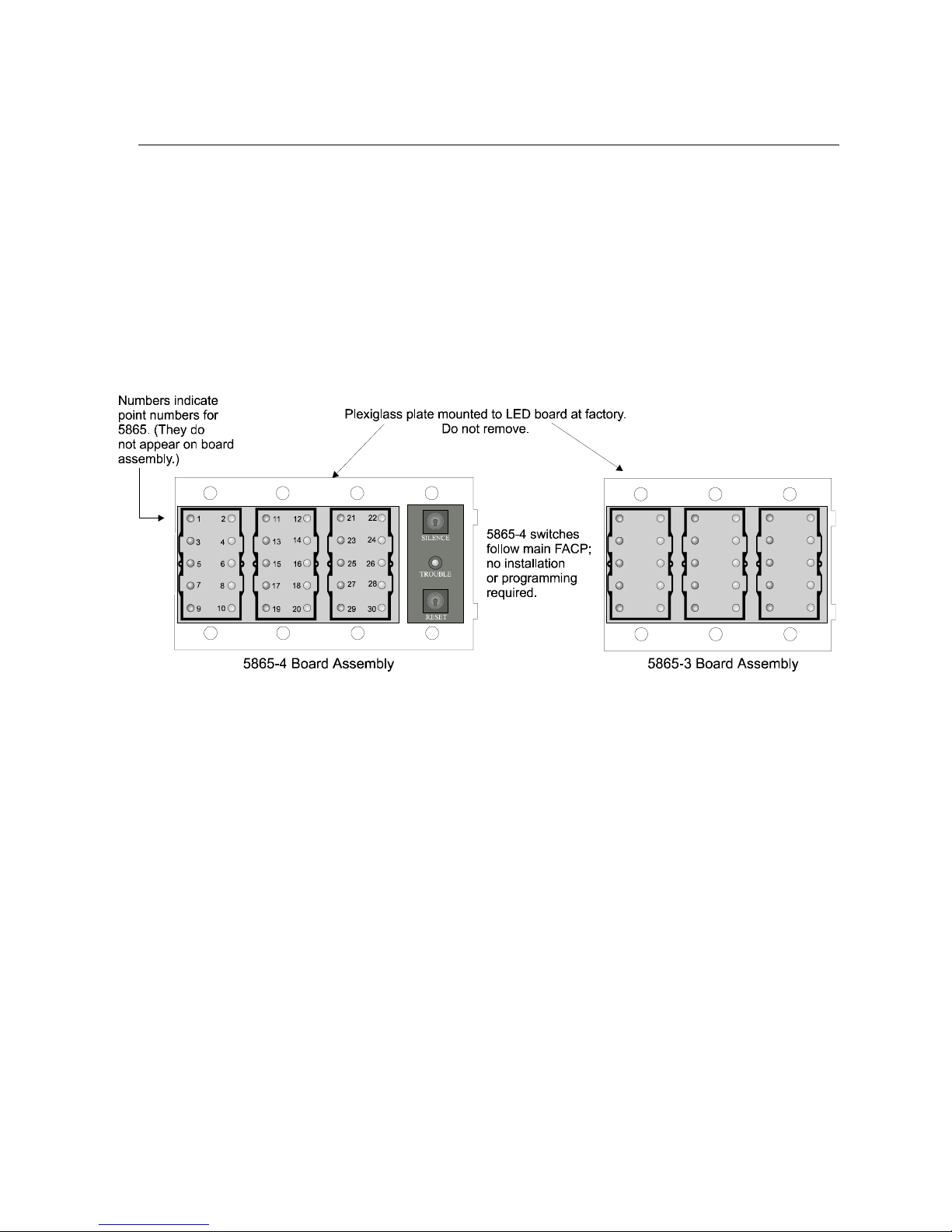
Model 5808 Installation and Operation Manual
4.8 5865-3 / 5865-4 LED Annunciator Installation
The 5865-3 and 5865-4 are LED annunciators. The 5865-4 has 30 mappable LEDs, remote
silence and reset key switches, and a general system trouble LED. The 5865-3 has 30
mappable LEDs only. These are arranged as 15 pairs of red (typically used for alarm) and
yellow (typically used for trouble) LEDs.
Installation of the 5865-3 and 5865-4 is identical. The key switches and the trouble LED
follow the behavior of other system annunciators and do not require any installation steps. The
following sub-sections describe how to install the 5865-3 and 5865-4 hardware. Refer to
Section 6 for programming information.
Note: This manual uses ì 5865î when referring to aspects of the 5865-3 and 5865-4 that are common to both
models.
Figure 4-21 5865-3 and 5865-4 Assembly (front view)
4-22 151274
Page 48

Control Panel Installation
4.8.1 FACP Connection
The 5865 connects to the panel via the SBUS. Make connections as shown in Figure 4-22.
After the 5865 is connected to the panel, it must be added to the system. This programming
step is described in Section 4.9.
Supervised
Power Limited
Figure 4-22 5865 Connection to the FACP
4.8.2 5865 Mounting
Mount the 5865-4 to a standard 4-gang electrical box. Mount the 5865-3 to a standard 3-gang
electrical box. In Figure 4-23, the 5865-4 attached to a 4-gang box is used as an example.
The 5865 ships with a set of zone description labels that can be inserted into the 5865 board
assembly. These labels can be used in a typewriter or can be written on by hand.
151274 4-23
Figure 4-23 5865 Mounting Example
Page 49

Model 5808 Installation and Operation Manual
Slide the labels under the plexiglass as shown in Figure 4-24. The LEDs will show through the
label when illuminated.
Figure 4-24 Inserting Zone Description Labels
4-24 151274
Page 50

Control Panel Installation
4.9 Configuring Modules
This section describes how to configure any system hardware modules that have been added
to the system.
4.9.1 Assigning Module IDs
When installing a hardware module (such as, 5824, 5860, 5496, 5865-3 or 5865-4), you must
use the dipswitches on the module to assign an ID# to the module.
Figure 4-25 shows all possible dipswitch positions and their correlation to a numerical ID. For
example, to select ID 2, place dipswitch 2 in the up position.
Refer to Section 7.1 to edit, add, delete, and view module list.
151274 4-25
Figure 4-25 Possible module addresses
Page 51

Model 5808 Installation and Operation Manual
4.10 Telephone Connection
Connect the telephone lines as shown in Figure 4-26. The Model 7860 phone cord is available
from Silent Knight for this purpose.
A number of programmable options are available for customizing telephone lines. These
options are described in Section 7.5.
Supervised
Figure 4-26 Connection of Telephone Lines
4-26 151274
Page 52

Control Panel Installation
4.11 Notification Appliance/Auxiliary Power Circuits
Four outputs are built-in to the 5808 FACP which can be programmed to be used as NACs
(Class A or Class B) or as Aux power.
This section of the manual explains how to install conventional notification appliances and
how these terminals can be used for auxiliary power.
4.11.1 Conventional Notification Appliance
This sub-section of the manual explains how to install conventional notification appliances for
Class A (Style Z) and Class B (Style Y) configurations.
4.11.1.1 Class B Notification Wiring
You must use an appliance from the list of compatible appliances in the Appendix A at the
back of this manual.
To install a Class B notification appliance circuit:
1. Wire Class B Notification appliances as shown in Figure 4-27.
2. Configure the circuit through programming (see Section 7.4).
UL Listed EOL
Model 7628
4.7 kΩ
Alarm Polarity
Shown.
Figure 4-27 Class B Notification Appliance Circuit Wiring
151274 4-27
Notification Wiring
Supervised
Power Limited
Page 53

Model 5808 Installation and Operation Manual
4.11.1.2 Class A Notification Wiring
You must use an appliance from the list of compatible appliances in the Appendix at the back
of this manual.
To install a Class A notification appliance circuit:
1. Wire the Class A notification appliances as shown in Figure 4-28.
2. Configure the circuit for Class A in programming (see Section 7.4).
Supervised
Power Limited
Figure 4-28 Class A Notification Appliance Circuit Configuration
4-28 151274
Page 54

Control Panel Installation
4.11.2 Auxiliary Power Installation
NAC Circuits 1-4 on the control panel can be used as auxiliary power circuits. The three types
of auxiliary power available are:
ï Door Holder (see section 4.11.2.1)
ï Constant (see section 4.11.2.2)
ï Resettable Power (see section 4.11.2.3)
Auxiliary power circuits are power limited. Each circuit can source up to 3A (total current for
all NAC circuits must not exceed 6A).
To install an auxiliary power circuit:
1. Wire the NAC circuit(s) that will be used for auxiliary power. See Figure 3-2 for location
of NAC circuits.
2. Configure the auxiliary power output through programming (see section 7.4).
4.11.2.1 Door Holder Power
Door holder power is intended for fire door applications. When there are no alarms in the
system and the panel has AC power, door holder circuits have 24-volt power present at their
terminals. Any alarm will cause power to disconnect. Power will be re-applied when the
system is reset. If AC power is off for more than 15 seconds, the auxiliary door holder power
will be disconnected to conserve the battery backup. When AC power is restored, power is
immediately restored to the door holder circuits.
Supervised
Power Limited
Figure 4-29 Example of an Auxiliary Power For Door Holder
Note: Figure 4-29 uses UL listed door holder Model 1400 from Door Control International as an example.
151274 4-29
Page 55

Model 5808 Installation and Operation Manual
4.11.2.2 Constant Power
Use constant power for applications that require a constant auxiliary power source. Power is
always present at Constant circuits.
4.11.2.3 Resettable Power
Resettable power is typically used to power beam detectors, flame detectors and conventional
4-wire smoke detectors. For circuits selected as Resettable, 24-volt power is always present at
the terminals unless a system reset occurs. If a system reset occurs, power is disconnected
from the terminals for 30 seconds, then re-applied.
4.12 On-Board Relays (Conventional)
The control panel has two built-in programmable relays and a built-in trouble relay. All relays
are Form C rated at 2.5 A @ 24 VDC.
Connect to Power
Limited Sources only
Figure 4-30 Location of Conventional Relay Circuits
Note: The N.C. contact is the relay contact that is closed when the panel has power and there are no alarm or
trouble conditions.
4.12.1 Trouble Relay
The control panel has a dedicated Form C trouble relay built into terminals labeled
TROUBLE. The relay provides a normally open and a normally closed contact. The trouble
relay will deactivate under any trouble condition.
4.12.2 Programmable Relays
The control panel has two Form C programmable relays built into terminals labeled RELAY 1
or RELAY 2. Each relay provides a normally open and a normally closed contact.
To install one or two programmable relays, follow these steps.
1. Wire Relay 1 and/or Relay 2 as needed for your application. See Figure 4-30 for the location of the relay terminals.
2. Configure the relay through programming (see section 7.4).
4-30 151274
Page 56

Control Panel Installation
4.13 Remote Station Applications
4.13.1 Keltron Model 3158 Installation
The control panel is compatible with Keltron Model 3158, used for direct connection to a
Keltron receiver. The 3158 reports alarms, supervisories, and troubles.
The steps for connecting the 3158 to the control panel. Refer to the 3158 installation
instructions for complete information.
1. Wire the 3158 to the control panel as shown in the connection list and Figure 4-31.
2. Wire the 3158 within 20 feet of the control panel. Wiring must be enclosed in conduit.
3. Program control panel Relay 2 for alarm.
4. Program NAC circuit 2 for alarm.
5. Program NAC circuit 1 for supervisory non latching.
Note: NACs must be programmed for continuous and non-silencing.
Figure 4-31 Keltron 3158 Connection to Control Panel
151274 4-31
Not suitable for remote station protected premises service
where separate transmission circuits are required for fire
supervisory (if applicable), and trouble signals.
Page 57

Model 5808 Installation and Operation Manual
4.13.2 City Box Connection Using the 5220 Module
This section describes how to connect the control panel to a municipal fire alarm box or ì city
boxî as required by NFPA 72 Auxiliary Protected Fire Alarm systems for fire alarm service.
The city (master) box is an enclosure that contains a manually operated transmitter used to
send an alarm to the municipal communication center which houses the central operating part
of the fire alarm system.
City Box Standby Current: 0 (Notification supervision current
accounted for in control panel draw.)
Alarm Current: 1 Amp for 1 second
The maximum coil and wire resistance (combined) must not exceed 30 ohms.
To install the 5220 for city box connection:
1. Use one of the knockouts on the right side of the control panel to connect the 5220 using a
short piece of conduit (must not exceed 20 feet in length).
2. Wire the 5220 to the control panel as shown in Figure 4-32. This drawing also shows how
to connect the city box coil to terminals 3 and 4 on the 5220. Do not install an EOL resistor in the terminals of the NAC circuit used for this application.
3. Connect earth ground wire to the 5220 chassis with mounting screw.
4. Program the NAC circuit used as a continuous and non-silencing. Refer to Section 7.4.1
for zone grouping and mapping.
It is not possible to reset the remote indication until you clear the condition and reset the
control panel.
Non-Supervised
Non-Power Limited
Note:
NAC Circuit 4 Used
as an example.
Any NAC circuit
could be used.
4-32 151274
Figure 4-32 City Box Connection
Page 58

Control Panel Installation
4.13.3 NFPA 72 Polarity Reversal
4.13.3.1 Using the 5220 Module
When the 5220 is wired and programmed for polarity reversal, it reports alarm and trouble
events to a remote site. Alarms will override trouble conditions and it will not be possible to
reset the remote indicator until the condition is cleared and the control panel is reset.
If an alarm condition occurs, the alarm relay will close, overriding the trouble condition.
Standby Current: 100 mA
Alarm: 100 mA
To install the 5220 for polarity reversal, follow the steps below:
1. Locate the knockout on the right side of the control panel cabinet to connect the 5220
using a short piece of conduit (must not exceed 20 feet in length).
2. Wire the 5220 to the control panel using the four-wire pigtail provided as shown in Figure
4-33. This diagram also shows how to connect the 5220 to the remote indicator. Do not
install an EOL resistor in the terminals of the NAC circuit used for this application.
3. Connect earth ground wire to the 5220 chassis with mounting screw.
4. Program the NAC circuit used as continuous and non-silencing. Refer to Section 7.4.1 for
zone grouping and mapping.
151274 4-33
Page 59
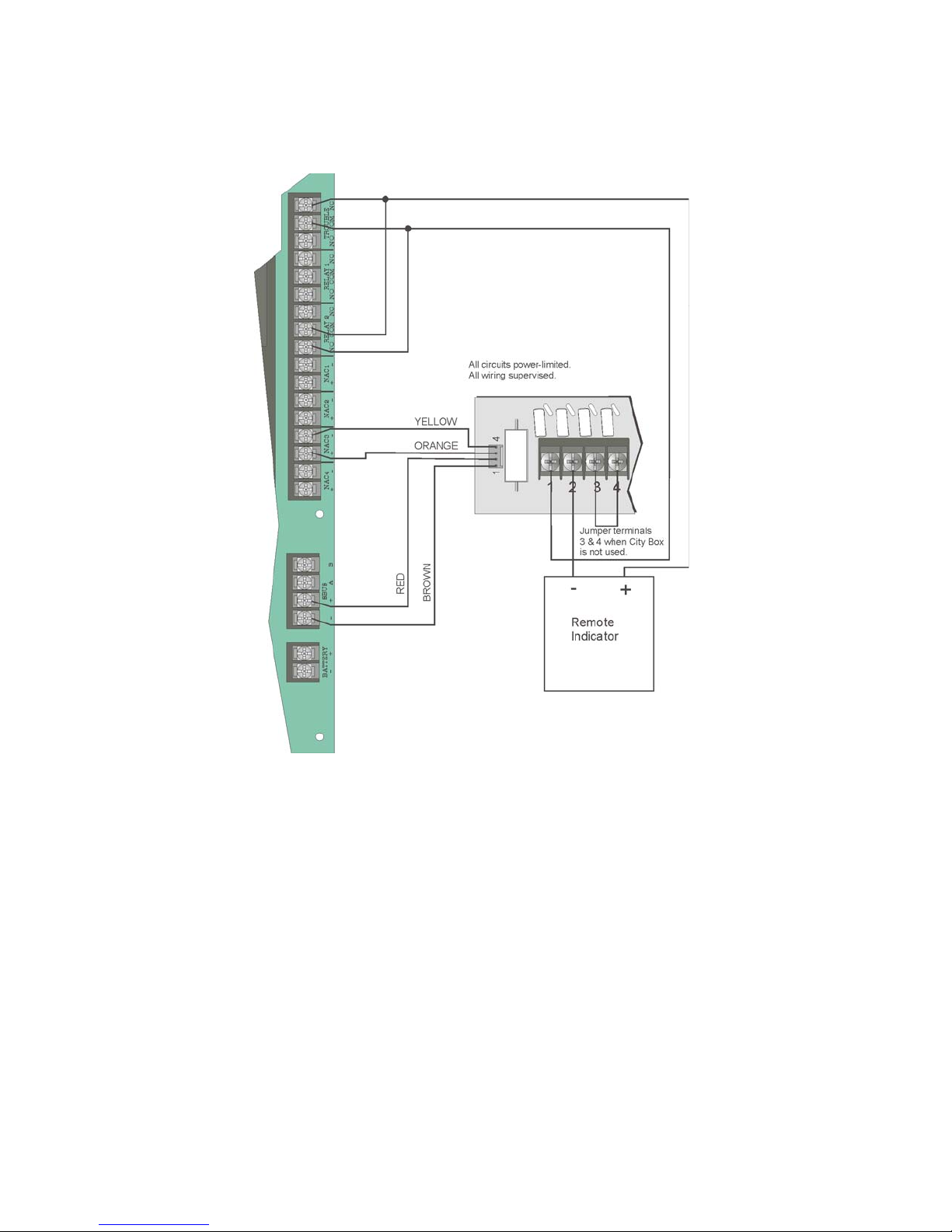
Model 5808 Installation and Operation Manual
5. If necessary, adjust loop current using the potentiometer (R10) on the 5220 board . Normal loop current is 2-to-8 mA with a 1k ohm remote station receiving unit. Maximum loop
resistance is 3k ohm.
Note:
NAC circuit 1 and Relay 1
used as examples. Any
NAC circuit and either
relay 1 or relay 2 could
be used.
Figure 4-33 Polarity Reversal Connection Using the 5220 Module
4-34 151274
Page 60

Control Panel Installation
4.13.4 Using the SD500-ARM Addressable Relay Module
When the SD500-ARM is wired for polarity reversal, it reports alarm and trouble events to a
remote site. Alarms will override trouble conditions and it will not be possible to reset the
remote indicator until the condition is cleared and the control panel is reset.
Relay 2 must be programmed for Alarm (default).
Note: If you need to transmit supervisories or trouble conditions, additional SD500-ARM modules must be added.
Use relay 1 to transmit supervisory conditions. Use the trouble relay to transmit trouble conditions.
Wire the SD500-ARM as shown in Figure 4-34.
Supervised
Power Limited
Intended for Connection to a
Polarity Reversal Circuit of A
Remote Station Receiving Unit
Having Compatible Rating.
Figure 4-34 Polarity Reversal Connection Using the SD500-ARM Module
151274 4-35
To Remote
Receiving Station
UL Listed
Model 7642
Page 61

Model 5808 Installation and Operation Manual
4.13.5 Using a MR-201/T Control Relay From Air Products
When the MR-201/T control relay is wired for polarity reversal, it reports alarm and trouble
events to a remote site. Alarms will override trouble conditions and it will not be possible to
reset the remote indicator until the condition is cleared and the control panel is reset.
If an alarm condition occurs, the alarm relay will close, overriding the trouble condition.
Current: 15 mA max.
Operating Voltage: 24 VDC nominal
Resistance: 4 KΩ
To install the MR-201/T for polarity reversal, follow the steps below:
1. Wire the MR-201/T as shown in Figure 4-35.
Intended for Connection
to a Polarity Reversal
Circuit of A Remote
Station Receiving Unit
Having Compatible
Rating.
Supervised
Power Limited
Figure 4-35 Polarity Reversal Connection Using the MR-201/T Relay
2. Program the NAC circuit for non silence NAC circuit (see Section 7.4).
Note: If you need to transmit supervisories or trouble conditions, additional relay modules must be added. Use
relay 1 to transmit supervisory conditions. Use the trouble relay to transmit trouble conditions.
4-36 151274
Page 62

Section 5
SLC Device Installation
Caution
To avoid the risk of electrical shock and damage to the unit, power should be OFF at the control panel while
installing or servicing.
5.1 Types of SLC Devices
The following types of SLC devices can be used with the system.
ï Model SD500-AIM Input Module (switch input), standard size, dipswitch configurable
ï Model SD500-LED Addressable LED Driver Module. Capable of driving 80 LEDs, Up
to 40 SD500-LED modules can be used per SLC loop. Refer to SD500-LED Installation
Instruction P/N 151232.
ï Model SD500-MIM Mini Input Monitor Module (switch input), small size, dipswitch
configurable. Fits in single-gang box with manual pull station switch.
ï Model SD500ARM Addressable Relay Module, dipswitch configurable
ï Model SD500-LIM. SLC short circuit isolator module. Fits in a double gang box. Refer
to SD500-LIM Installation Instructions P/N 151125.
ï Model SD505-6IB. Short circuit isolator base for SD505-AHS, SD505-AIS, and SD505-
APS SLC devices. Refer to SD505-6IB Installation Instructions P/N 151175.
ï Model SD505-AHS Heat Sensor
ï Model SD505-AIS Ionization Smoke Detector
ï Model SD505-APS Photoelectric Smoke Detector
ï Model SD505-ADH Duct Housing (used with SD505-AIS or SD505-APS smoke
detectors)
ï Model SD505-ADHR Duct Detector Housing With Relay (used with SD505-AIS or
SD505-APS smoke detectors). Refer to SD505-ADHR Installation Instructions P/N
151126.
ï Model SD505-DTS Remote Test Switch & LED indicator for the SD505-ADHR.
ï Model SD500-PS Addressable pull station. Refer to SD500-PS Installation Instuctions
P/N 151177.
151274 5-1
Page 63

Model 5808 Installation and Operation Manual
5.2 Maximum Number of Devices
A total of 127 addressable devices can be used with the system.
5.3 Wiring Requirements for SLC Devices
The following information applies to all SLC devices. Refer to the section that describes the
type of device you are installing for details.
5.3.1 Wiring SLC devices in Style 4 (Class B)
No special wire is required for addressable loops. The wire can be untwisted, unshielded, solid
or stranded as long as it meets the National Electric Code 760-51 requirements for power
limited fire protective signaling cables.
Maximum wiring resistance is 50 ohms.
Maximum loop length depends on the wire gauge.
Wire Gauge Max. Distance
22 AWG 1500 feet
18 AWG 3900 feet
16 AWG 6200 feet
14 AWG 10,000 feet
Figure 5-1 and Figure 5-2 show how wire length is determined for out-and-back tap and T-tap
style wiring.
Figure 5-1 Calculating wire run length for a simple out and back
5-2 151274
Page 64

SLC Device Installation
When using T-taps, the total length of all taps and the main bus must not exceed 40,000 feet.
This requirement must be met in addition to the maximum distance requirements for the
various wire gauges.
Figure 5-2 Calculating Wire Run Length for a T-tap
151274 5-3
Page 65
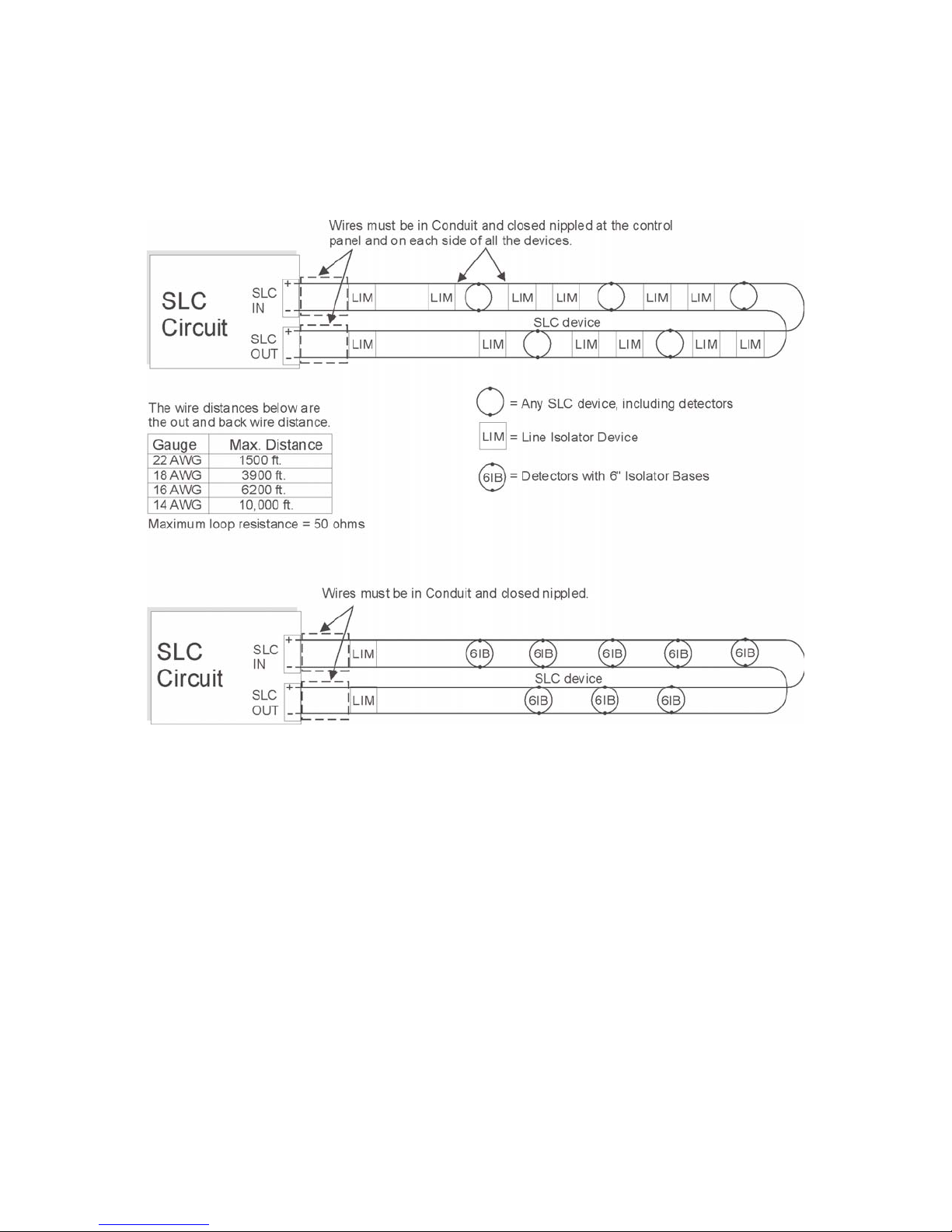
Model 5808 Installation and Operation Manual
5.3.2 Wiring SLC Devices in Style 6 & 7 (Class A)
Figure 5-3 illustrates how to wire the SLC loop for Style 6 or Style 7 Class A installations.
Note: Style 6 does not use short circuit isolator devices.
Figure 5-3 Class A SLC Configuration
Note: No t-taps allowed on class A SLC loops.
5-4 151274
Page 66

SLC Device Installation
5.4 Heat and Smoke Detector Installation
The information in this section applies to the following models: SD505-AHS Heat Detector,
SD505-AIS Ionization Smoke Detector, and SD505-APS Photoelectric Smoke Detector.
See also Section 5.9 for information on how to address the detectors.
5.4.1 Wiring
1. Wire device bases as shown in Figure 5-4.
2. Set the address for each device as described in Section 5.9.
3. Connect the device as shown in Figure 5-4.
Figure 5-4 Heat or Smoke Detector Connection to the FACP
151274 5-5
Page 67

Model 5808 Installation and Operation Manual
to duct detector base
5.5 Duct Detector Installation
Figure 5-5 shows the layout of the SD505-ADH duct housing with a detector base in place,
including location of the terminals for connection to the FACP. Figure 5-6 shows wiring in
detail.
Address the detector head before attaching it to the base. This procedure is explained in
Section 5.9.
Connect tubes at back of housi ng.
Exhaust Tube
2
1
5
6
3
4
1234
Pre-wired connections
Inlet Tube
Detector Base
Terminals on detector
base ar e for SLC lo op
not
connection. Make loop
connections below.
Connec t to
SLC loop.
See Fig. 5
for wiring details.
.
Figure 5-5 Model SD505-ADH Internal View Showing Connector Locations
Figure 5-6 Duct Detector Connection to the Control Panel
5-6 151274
Page 68

SLC Device Installation
5.6 Input Monitor Module (SD500-AIM)
Wire and mount the SD500-AIM full-size input module as described in this section (see
Figure 5-7 and Figure 5-8). See Section 5.9.2 for information on how to use the on-board
dipswitch to select an address for the module.
Wire the monitor modules to the SLC as shown in Figure 5-7.
SD500-MIM
Control
Panel
SD500-AIM
Figure 5-7 SD500-AIM/MIM Input Module Connection to the FACP (Class B)
151274 5-7
Page 69

Model 5808 Installation and Operation Manual
Figure 5-8 SD500-AIM/MIM Input Module Mounting Example
5.7 Mini Input Module (SD500-MIM)
Wire the SD500-MIM Mini Input Module as shown in this section (see Figure 5-7 and Figure
5-8). The SD500-MIM fits inside a single-gang electrical box. See Section 5.9.2 for
information on using the on-board dipswitch to select an address for the module.
5-8 151274
Page 70

SLC Device Installation
5.8 Relay Module Installation
The information in this section applies to Model SD500-ARM Relay Modules. See Section
5.9.2 for information on how to use the on-board dipswitch to select an address for the
module.
5.8.1 Electrical Specifications
The following is electrical rating information for SD500-ARM relay modules.
Relay Ratings
30 VDC @ 2.0 A Resistive
30 VDC @ 1.0 A Inductive (.6PF)
30 VDC @ 0.6 A (0.35PF) Pilot Dutyó Light duty low voltage S.W.
120 VAC @ 0.6 A (0.35PF) Pilot Duty
Connect to power limited sources only.
Note: PF = Power Factor.
5.8.2 Wiring
Wire relay modules to the panel or to the SLC as shown in Figure 5-9.
Control Panel
Supervised
Power Limited
SD500-ARM
Figure 5-9 Relay Module Connection to the FACP (Class B)
151274 5-9
Page 71

Model 5808 Installation and Operation Manual
5.9 SLC Device Addressing
5.9.1 EEPROM Addressing
Select addresses for the following models through software as described here:
ï Model SD505-AHS Heat Detector
ï Model SD505-APS Photoelectric Smoke Detector
ï Model SD505-AIS Ionization Smoke Sensor
You must use the Installer Code to perform this task. Here are the steps.
1. Connect a detector base temporarily to the programming terminals as shown in Figure 5-
10. (You can use the same base for each detector.)
Figure 5-10 Temporary of Detector Base to Panel for Addressing
2. Enter the Installer code and Press .
3. Select for Point Functions.
4. Select for Set SLC Dev Addr.
2
3
5. Select ì Yesî by pressing the up arrow, then press . (The panel will go into
trouble at this point. You can use the key to stop the PZT. The trouble will clear
ENTER
ENTER
SILENCE
automatically when the panel reinitializes when you finish programming.)
6. When the wait message clears, the following options display:
1
for Read Address. Use to read (or check) a single detectorís address.
2
for Write Address. Use to program a single detectorís address.
3
for Seq. Programming. Use to program more than one detector in sequential order.
7. If you are changing addresses, write the programmed address on the back of the device.
8. To exit press left arrow until fully exited.
5-10 151274
Page 72

SLC Device Installation
5.9.2 Dipswitch Addressing
Input and relay module addresses are set using the dipswitch that appears on the module
board. The chart below shows the available addresses. For example, to select address 3, place
dipswitches 1 and 2 in the up position. The range of valid addresses is 1-127 (0 is an invalid
address).
Figure 5-11 SLC Device Addressing Using Dipswitches
151274 5-11
Page 73

Model 5808 Installation and Operation Manual
5-12 151274
Page 74

Section 6
Programming Overview
This section of the manual is intended to give you an overview of the programming process.
Please read this section of the manual carefully, especially if you are programming the control
panel for the first time.
The JumpStart feature automates many programming tasks and selects default options for the
system. You will run JumpStart at least once when you are installing the system. See Section
6.1 for details. After you run JumpStart, you may need to do some additional programming
depending on your installation. Section 7 of this manual covers manual programmable options
in detail.
Programming the panel can be thought of as a three part process. You must program:
ï System options. These are options that affect general operation of the panel (see Section
7.5 for details).
ï Options for input points and zones. These are primarily options that control detection
behavior of devices (see Section 7.4 for details).
ï Options for output points and groups. This includes selecting characteristics for output
groups and mapping output circuits to output groups (see Section 7.4 for details).
6.1 JumpStart Autoprogramming
The JumpStart feature allows for faster system setup. When you run JumpStart (immediately
after addressing SLC devices), the system scans devices on all SLC loops and determines
device type (for example, ionization smoke detector or heat sensor) and selects some system
options based on the device type. This saves the installer from having to program options for
each device. Depending on the application, the installer may need to make some changes after
JumpStart completes.
See Section 6.1.3 for complete details about running JumpStart.
IMPORTANT
JumpStart is intended to be run one time only, immediately after SLC devices have been addressed and connected.
JumpStart will reset all manually programmed options to default settings. Do not run JumpStart after you have
configured the system.
151274 6-1
Page 75

Model 5808 Installation and Operation Manual
6.1.1 Input Points
JumpStart will determine the number and type of input points (detectors or contact monitor
modules) on each SLC loop. JumpStart assigns the correct detector type (heat, ionization or
photoelectric), so the installer does not need to edit device type for detectors. Any contact
monitor modules on the system will be assigned type "Manual Pull." The installer will need to
manually change the switch type if manual pull is not correct.
JumpStart creates one zone (Zone 1) and assigns all input points to Zone 1. Zone 1 is mapped
to Output Group 1. After JumpStart completes, you can re-map to configure a multiple zone/
output group system (see Section 7.2.1.3). For a general explanation of mapping, see Section
6.2.
6.1.2 Output Points
JumpStart creates three output groups and assigns output circuits as follows:
Circuits 1-4:
Configured as Notification and assigned to Group 1. JumpStart automatically programs Zone
1 to activate Group 1 using constant on output.
Circuit 5 (Relay 1):
Assigned to Group 124. JumpStart automatically programs Zone 1 to activate Group 124
using constant on output when a supervisory condition occurs.
Circuit 6 (Relay 2):
Assigned to Group 125. JumpStart automatically programs Zone 1 to activate Group 125
using constant on output when an alarm occurs.
Addressable output points (Relay modules, NAC Modules, Sounder Bases, Relay Bases):
All addressable relay devices will be configured as "Output Pt" (general purpose output point)
and assigned to Group 1.
Note: Relay output is constant even if the zone activating the relay is programmed with an output pattern.
6.1.3 Running JumpStart
Run JumpStart immediately after you have addressed and connected all input devices
(detectors, pull stations, and so on) and output devices (notification appliances, relays, and so
on).
Note: If you need to install a few devices after you have run JumpStart, you can install them manually. Follow
instructions in Section 8 for configuration.
To run JumpStart, follow these steps.
1. Press to view the Main Menu.
2. Select for Program Menu.
7
3. From the next menu, select for JumpStart.
6-2 151274
6
Page 76

Programming Overview
4. The message "WARNING Will reset all system options" displays on the LCD. Select Yes
to continue. A series of messages displays for the next several seconds. JumpStart scans
the SLC loops for devices. This can take several minutes, depending on the number of
devices attached.
5. When the message "Configure System Done" displays on the LCD, press any key to continue.
6. Select one of the following options from the menu that displays.
1 1
- Review System Press if you need to review the JumpStart configuration.
2 2
- Repeat JumpStart Press if you need to rerun JumpStart for any reason.
3 3
- Accept Configuration 1. If you are ready to make the JumpStart configuration permanent, select .
2. The system will ask you if the installation contains duct detectors. If there
are none, select for No and skip to Step 8. If the system contains duct
detectors, select for Yes and continue with Step 3.
3. From the list that displays, select the SLC device that contains the duct
detectors.
4. The first photoelectric or ionization detector on the system will display.
1 2
Select for DUCT and for NonDUCT.
2
1
5. Press to select the next detector. Select for DUCT and for NonDUCT. Continue until all duct detectors have been selected. (Note: You
can move backwards through the list with .)
6. When you reach the last detector on this device, press .
7. The system will ask you if there are more duct detectors in the system. If
there are, select for Yes and repeat from Step 3. If there are no more
duct detectors, select for No and continue with Step 8.
8. The system will restart in 10 seconds. You can press to restart immedi-
ately. Do not select for System Diagnostics. (This feature is for use in
testing at the factory.)
9. After the system resets, it will use the new JumpStart configuration.
1
2
2
1 2
1
151274 6-3
Page 77

Model 5808 Installation and Operation Manual
6.2 Mapping Overview
This section of the manual is an overview of mapping. Details about how to select mapping
options appear in the appropriate subsections in Section 7.
Mapping is an important concept with the control panel. In general terms, mapping is
assigning or linking events to outputs that should activate when events occur. You do this by
assigning input points to input zones, output points to output groups and then linking or
mapping zones and output groups.
Figure 6-1 is a brief overview of the concept of mapping. The next several pages of the
manual show these subjects in detail.
Figure 6-1 Mapping Overview
6-4 151274
Page 78

Programming Overview
6.2.1 Input Point Mapping
Input points are assigned to input zones. Any input point can be assigned to any input zone.
(Input points can be assigned to one zone only. An input point can be designated as "Unused,"
which means it has not been assigned to a zone.)
Figure 6-2 Input Point Assignment Example
151274 6-5
Page 79

Model 5808 Installation and Operation Manual
6.2.2 Output Circuit Mapping
Figure 6-3 is a simple example showing how to assign notification and relay output circuits to
groups. For an example of a simple floor above/floor below application, see Figure 6-5.
Figure 6-3 Assigning Output Circuits to Groups (Example)
6-6 151274
Page 80

Programming Overview
6.2.3 Zone Event Mapping
There are 8 types of events that can occur in zones (see below). For each event type, you can
activate up to 8 output groups and patterns. If it is necessary to map to more than 8 output
groups, an output group template may be used (see Section 7.3.5 for information on output
group templates). Event types are:
ï Manual Pull Alarm
ï Water Flow Alarm
ï Detector Alarm (heat or smoke detectors)
ï Aux 1 and Aux 2 Alarm (user-specified alarm types)
ï Pre-alarm
ï Supervisory
ï Trouble
Figure 6-4 Example of Zone Events Mapped to Output Groups and Patterns
151274 6-7
Page 81

Model 5808 Installation and Operation Manual
Figure 6-5 Example of Zone Events Mapped to Output Groups and Patterns
6-8 151274
Page 82

Programming Overview
6.2.4 Mapping LED Points
Figure 6-6 is a simple example showing how LED points are mapped to zones and output
groups. Typically you would create two output groups for each zone, one for alarms and one
for troubles. (LED points are available when Models 5865-3/4 and/or 5880 are used with the
system.)
Figure 6-6 Example of LED Points Mapped to Output Groups
151274 6-9
(applies to Models 5865-3/4 and 5880)
Page 83

Model 5808 Installation and Operation Manual
6.3 Silent Knight Software Suite (SKSS)
There are two ways to program the control panel. One way is to program directly from an
annunciator, either the on-board annunciator or a Model 5860 Remote Annunciator.
Annunciator programming is explained in Section 6.4.
The other method for programming is through the SKSS. The downloading software is an
optional software package that allows you to easily program the control panel using a
Windows-based computer and a *modem (not sold by Silent Knight). The software works in
the following way. First you use the software to program options for the panel, saving the
options in a file. You can then download the file to the panel. The software includes an on-line
help system and a manual.
* See Section 1.3 for a list of modems that have been tested by Silent Knight for compatibility with the control
panel and the Silent Knight Software Suite.
6.4 Annunciator Programming
There are two ways to program a control panel. One way is through the SKSS (see Section
6.3).
The other method is to program directly from an annunciator, using either the on-board
annunciator or a Model 5860 Remote Annunciator.
The following subsections describe programming basics, including a description of editing
keys available for programming and how to move through programming menus. Section 7
contain specific information about individual programming options.
6-10 151274
Page 84

Programming Overview
6.4.1 Entering / Exiting the Program Menu
To enter the Program Mode:
1. Enter the Installer Code (factory programmed default code is 123456).
2. The display prompts you to press the or key to bring up the Main Menu (see Figure
6-7).
Figure 6-7 Keypad Enabled Screen
3. Then press . The menus described in Section 7 of this manual will display. Section 6.5
7
of this manual is a quick reference listing all programmable options and JumpStart
defaults.
To Exit Program Mode:
When you have completed working with the menus, press (left arrow) several times until
you are exited from programming mode. Two prompts will display. The first prompt is to
make sure you intended to leave the Program Menu (select Yes or No as appropriate). The
second prompt is for accepting all changes. If you select No, any changes you have made
since you entered the Program Menu will have no effect.
151274 6-11
Page 85

Model 5808 Installation and Operation Manual
6.4.2 Moving through the Menus
Figure 6-8 shows how to move through Menu screens, using the System Options screen as an
example.
Figure 6-8 Moving through Program Menu
(System Options Sub-Menu Used as an Example)
6.4.3 Selecting Options and Entering Data
There are several ways to make programming selections using the control panel depending on
which screen you are currently using. The chart below is a generic explanation.
To Press
Select from a menu. Enter the number of the option.
Enter numeric data. Press the appropriate number on the annunciator.
Enter text (alphanumeric data). Enter each letter individually by pressing and holding any numeric key until the
one you wish to select displays. Then press (right arrow) to select the letter. See
Section 6.4 for complete information.
Select from a scrolling list.
Use (up arrow) and (down arrow) to move through a list of available
options. When the option you want to select is displayed, press .
6-12 151274
Page 86

Programming Overview
6.4.4 Editing Keys
The keys shown in Figure 6-9 are available for use when you are in the Program Menu.
Figure 6-9 Editing Keys Available from Program Menu
151274 6-13
Page 87

Model 5808 Installation and Operation Manual
6.5 Programming Menu Quick Reference
This section of the manual lists all Program Menu options in the order they appear on the submenus. Default settings are indicated in text or marked with an asterisk. The comments
column provide quick information and a reference to a section (if applicable) which has more
detailed information.
Menu Options/Defaults Comments
Internal SLC Enter Module Name Select Class
Internal Pwr Enter Module Name
Internal Annu Enter Module Name
Edit Module
Module
Add Module
Delete Module List of Modules See Section 7.1.3
View Module List List of Modules
5496 Enter Module Name
5865 Enter Module Name
5880 Enter Module Name
5824 Enter Module Name
5860 Enter Module Name
5860-Keystation
5824-Ser/Par/IO
5496-IO/Pwr Sup
5880-LED/IO Dev
5865-LED Annunc
See Section 4.9
See Section 7.1.2
6-14 151274
Page 88

Programming Overview
Menu Options/Defaults Comments
Enter Name1
Enter Number1
Enter Name2
Enter Number2
*1 Count
2 Count
Verification
Type
Heat Temp Set 135∞ to 150∞F
Manual Pull
(MP)
Wat er Flow
(WF)
Detector Alarm
(DE)
Aux 1 (A1)
Pre-alarm (PR)
Supervisory
(SU)
Trouble (TR) no group
Cadence 00-20
Local Zone Yes or No
Alarm Ver.
PA S
SNGL ILOCK
DBL ILOCK
(Groups 01 &
250, Pattern
00)
no groupAux 2 (A2)
(Group 249,
Pattern 00)
Sec. 7.2
Sec. 7.2.3
Sec. 7.2.4
Zone
Edit Zone Name
Zone Properties
Edit Zone Select Zone to Edit
Zone Outputs
Zone Accessry Opt
Add Zone Adds next available zone number. Sec. 7.2.2
Delete Zone
View Zone Points
Select Zone to be
Deleted
List of all points in
selected zone.
151274 6-15
Page 89

Model 5808 Installation and Operation Manual
Menu Options/Defaults Comments
Enter Name1
Group
Edit Group Select Group
Add Group
Delete Group
View Group Points Select Group
Edit OPG
Template
Select Group to
Delete
Select Template
Number
Group Name
Group Properties
Select Group
Include in template
Select Pattern 0-20 0 = Constant. Refer to Figure 7-5
Enter Number1
Enter Name2
Enter Number2
Latching
Options
Silencing
Options
Group Active
With:
Ye s
No
See Section
7.3.1.1.
*NonLatching
Latching
*SILENCE Silenceable
NON-SIL Non-Silenceable
Auto
Unsilence
SIL-INHIB Silence after inhib
SHUTDOWN
Group
Activates for
all Man. Pull
Group
Activates for
Fire Drill
Group
Activates for
Aux 1
Group
Activates for
Aux 2
Ignore Global
Cadence
Sec. 7.3.3
Sec. 7.3.1.1
Sec. 7.3.1
Auto Un-silenced
Sec. 7.3.1
delay. Sec. 7.3.1
Automatic
Shutdown Sec.
7.3.1
*No
*Yes
*No
*No
*No
6-16 151274
Page 90

Programming Overview
Menu Options/Defaults Comments
UNUSED
PHOTO
ION
Point
SLC Loop Enter Pt
Select Type
Internal Pwr and
External Power
Select Group or
Zone Number
Edit Name Enter Name See Section 7.4
Enter Point #
5880
5865
Select Group #
Edit Name Enter Name
Enter Point #
Select Group #
Edit Name Enter Name See 7.4
DETECTOR
SWITCH
RELAY
UNUSED
B NOTIF
A NOTIF
AUX PWR
NOTIF
UNUSED
NOTIF
UNUSED
HEAT
PHOT DUCT
ION DUCT
MAN_PULL
WATERFLOW
SUPERVSY LATCH
FIREDRILL
SILENCE
RESET
PA S_ AC K
ZN_AUX1
ZN_AUX2
SYS_AUX1
SYS_AUX2
DETECT SW
TAMP ER
OUTPUT PT Select Group
AUX CONST
AUX RESET
AUX DOOR
Select Group
CONSTANT
RESETABLE
DOOR
Select zone See Section 7.4.
LATCH
NLATCH
NLATCH
LATCH
NLATCH
LATCH
NLATCH
LATCH
NLATCH
LATCH
NLATCH
Group or Zone selection will
appear depending on the type is
selected
See Section 7.4.
See Section 7.4.
151274 6-17
Page 91

Model 5808 Installation and Operation Manual
Menu Options/Defaults Comments
For each account (1-4), select:
Edit Account # *123456 Account # (6-digit
number, identifies
account to central
station)
Sec. 7.5.1
Edit Format *Contact ID Reporting Format
(SIA, S20,
Contact ID)
Sec. 7.5.1
Y (Yes) *Yes Sec. 7.5.1
System
Options
Reporting
Accounts
Edit Acct.
Auto Test Time
Report Alarms
Rep. Alarm Restore
Report Troubles,
Supervisories,
Enable/Disable
Report Test
Report Resets
Switch attempts 1 - 5 *5 Sec. 7.5.2
Edit Phone #1 up to 24 digits blank Sec. 7.5.2
Set the Hour
Select AM/PM
N (No)
M (Must)
Y (Yes) *No
N (No)
M (Must)
Y (Yes)
N (No)
M (Must)
Y (Yes)
N (No)
M (Must)
Y (Yes)
N (No)
M (Must)
*02:00 AM Sec. 7.5.1.2Set the Minutes
6-18 151274
Page 92

Programming Overview
Menu Options/Defaults Comments
For each phone line (1 & 2), select:
Dialing Prefix Up to 8 digits none Sec. 7.5.2.1
# of Answer Rings Range: 00-15 06 Number of rings
before panel
answers a call
from a computer
Sec. 7.5.2.2
System
Option
(cont.)
Phone Lines Select Phone Line
Trouble Events
System Event
Outputs
Sys Alarm Cadence
TT
TT/PL TouchTone
Select Dialing
Option
PULSE Pulse dialing
Rotary Pulse Format
Line Monitor
Not Used
Answering Machine
Bypass
System Trouble
Alarm Silence Select Group
Trbl Silence
User Selected
Fire Drill
System Aux2
U = 60/40
E = 66/34
Yes *Ye s S e c. 7. 5. 2. 5
No
Yes = e n a bled
No = disabled
Yes = e n a bled
No = disabled
Select Group
Select Cadence Sec. 7.5.3.1
Select Cadence
Select Group
Select Cadence
Group Tr
SBUS Com
SBUS Pwr
SLC Loop
AC Loss
Battery
Gnd Flt
Phone Ln
Account
Printer
Aux Pwr
Sys Sw
Select Cadence ConstantSystem Aux1 Sec.7.5.3.2
TouchTone
*U
*N = Disabled
*Y = Enabled
None selected
None selected
None selected
Select Group
Select
Cadence
Touch Tone
alternating with
pulse see Section
7.5.2.3
Sec. 7.5.2.4
Sec. 7.5.2.6
Sec. 7.5.2.7
Sec. 7.5.3.1
151274 6-19
Page 93

Model 5808 Installation and Operation Manual
Menu Options/Defaults Comments
0 - 90 Seconds *30 sec Water Flow delay is the number
System
Option
(cont.)
JumpStart
AutoPrg
Computer
Account
Water Flow Delay
6 - 30 hours *6 hrs Low AC Report
Low AC Delay
Misc. Options
Misc. Options 2
Edit Banner
No See Section 7.6
Ye s
Computer Account
#
Computer Access
Code
Computer Phone # Up to 24 digits
DST
CLK
AC Freq:
SYNC Strbs w/ Sil
Auto Display Oldest
Report By
Internal Message See Section 7.5.6
Custom Message
*123456
*0
Y (Enabled)
N (Disabled)
AM/PM
MIL
50 Hz See Section
60 Hz
Neither
Y (Enabled)
N (Disabled)
Y (Enabled)
N (Disabled)
Zone
Point
Edit Line 1
Edit Line 2
*Enabled
*AM/PM
*Enabled
*Disabled
*Zone
of sec before water flow alarm is
generated. Sec. 7.5.4.1
Delay. Sec.
7.5.4.2
Automatic daylight Savings
enable or disable. Sec. 7.5.4.3
System Clock Format (AM/PM or
military). Sec. 7.5.4.4
7.5.4.5
See Section
7.5.5.1
See Section
7.5.5.2
See Section
7.5.5.3
See also Section 7.7
See Section 7.7 for programming
phone number.
6-20 151274
Page 94

Programming Overview
Menu Options/Defaults Comments
Edit Name
Edit Access Code
System Reset
System Silence
System Event Ack.
Fire Drill Key
System Tests
Fire Drill Menu
Indicator Test
Walk Test noReport
Wal k Te s t w /Re po r t
Access
Codes
Select Profile
(01 - 20)
Edit Panel
Functions
Dialer Test
Clear History Buffer
Point Functions
Disable/Enable
Point
Point Status
Set SLC Device
Address
SLC Device Locator
SLC Multi-Device
Locator
I/O Point Contol
Event History
Set Time & Date
Printer Options
Event Logging
Print Event History
Print Detector
Status
Print System Config
Reset Dialer
Program Menu
System Information
Upload/Download
Profile 1 is the profile that dictates
what functions the Fire Fighter
Key has access to. Because this is
the profile for a key the user name
and the access code can not be
edited for this profile.
Profile 2 is the profile for the
installer and is referred to as the
"Installer Code". This profiles
user name and panel functions can
not be edited.
See Section 7.8.
151274 6-21
Page 95

Model 5808 Installation and Operation Manual
6-22 151274
Page 96

Section 7
Programming
This section of the manual describes how to manually program the control panel from the
built-in annunciator. Each subsection discusses these menu options in detail. All options
described in this section can be performed using the Silent Knight Software Suite 5660.
Important!
Before any customized programming is done, JumpStart should be run first. After
JumpStart is run, thoroughly test the system. The reason the system should be tested
after JumpStart is because Jumpstart automatically programs the system, searching for
and configuring all SLC and SBUS devices it finds. JumpStart allows you to confirm
the integrity of the installation prior to performing any custom programming. After
determining that the hardware is properly installed, custom programming can be
performed. Refer to Section 6.
7.1 Modules
This section lists the options available under the module option in the program menu. The
types of modules available for the control panel are, 5860 (Keystation), 5824 (Serial/Parallel
input/output), 5880 (LED Input/Output module), 5496 (Intelligent Power Module), and a
5865 (LED Annunciator).
7.1.1 Edit Modules
The features that can be edited when this option is selected are, module name, and class of
wiring (Class A or Class B).
To edit an existing module, follow these steps:
1. Enter the installer code.
1. Press
2. Select for Program Menu.
Display reads: Initializing
3. Press to enter module menu.
4. Press to edit a module.
5. Use the or arrow to select the module you wish to edit.
or to display the main menu.
7
Please wait . . .
1
1
151274 7-1
Page 97

Model 5808 Installation and Operation Manual
7.1.1.1 Naming Modules
You can assign an English name to a system hardware module to make it easier to recognize
on a display.
6. If you wish to edit the modules name press the or arrow to select each character
for the modules name (or press to bypass name edit).
Press the to move to the next character.
Figure 7-1 Edit module Name Programming Screen Example
7.1.1.2 Module, Wiring Class
7. Choose the class of wiring you wish to use for this module by pressing the or
arrow, then press .
7.1.2 Adding a Module
If you need to add a new hardware module to the system, follow these steps.
You must be in the Main Menu to perform this task. If necessary, enter the Installer Code.
1. Press or to display the main menu.
2. Select for Program Menu.
Display reads: Initializing
3. Press to enter module menu.
7
Please wait . . .
1
4. Press to add a module.
7-2 151274
2
Page 98

Programming
5. From the next screen, select the number that corresponds to the type of module you are
adding from the <New Module Type> screen.
The screen will display ì Adding module [#]...î for a few moments. You will be returned
to the <New Module Type> screen where you can select another module if desired.
You must save changes when you exit the Program Menu or the new module will not be
added.
Note: If you Add a Module that has not been physically connected, the panel will go into trouble after it
reinitializes (when you exit the Program Menu). When the new module is attached, the trouble will correct
itself automatically the next time you power up the system.
7.1.3 Deleting a Module
If you ever need to delete a module, follow these steps.
You must be in the Main Menu to perform this task. If necessary, enter the Installer Code.
1. Enter the installer code.
2. Press or to display the main menu.
3. Select for Program Menu.
7
Display reads: Initializing
Please wait . . .
4. Press to enter module menu.
5. Press to delete a module.
1
3
6. A warning screen will display. If you want to proceed with deleting the module, select
Yes. To cancel, select No.
151274 7-3
Page 99

Model 5808 Installation and Operation Manual
7.2 Zone
Through the zone option in the program menu you can edit, add, delete, and view zone points.
Selections made here affect all detectors and switches in the zone. Up to 125 zones can be
used in the system.
7.2.1 Edit Zone
Features that can be edited through the edit zone option are, edit zone name, zone properties
(which includes, zone type, and detector sensitivity), and zone output mapping.
To edit a zone, follow these steps:
1. Enter the installer code.
2. Press
3. Select for Program Menu.
or to display the main menu.
7
Display reads: Initializing
Please wait . . .
4. Press to enter zone menu.
5. Press to edit a zone.
2
1
6. Enter the zone number, then press .
7.2.1.1 Edit Zone Name
7. Press to edit the selected zoneís name.
A screen similar to the one shown in Figure 7-2 displays.
1
Figure 7-2 Selecting Character for Zone Name
7-4 151274
Page 100

Programming
8. Select the characters for the zone name by pressing the or arrow until the desired
character is shown then press .
OR
Enter the Numerical Designator for the character you want, then press . See Appendix B
Table B-1 of this manual for a list of available characters and their numeric designators.
9. Repeat step 8 until the name is complete.
10. Press when the name is complete.
7.2.1.2 Edit Zone Properties
Zone properties consist of, alarm delay characteristics, and heat detector sensitivity.
1. Do steps 1 through 6 of Section 7.2.1.
2. Press to edit the properties of the selected zone.
2
Detection type also selected from
this screen (see Table 7-1).
151274 7-5
 Loading...