


Siemens SINUMERIK 840DE, SINUMERIK 840D, SINUMERIK 840DE powerline, SINUMERIK 840D powerline, SIMODRIVE 611 digital User Manual
RGB ELEKTRONIKA AGACIAK CIACIEK
SPÓŁKA JAWNA
Jana Dlugosza 2-6 Street
51-162 Wrocław
Poland
biuro@rgbelektronika.pl
+48 71 325 15 05
www.rgbautomatyka.pl
www.rgbelektronika.pl
DATASHEET
www.rgbautomatyka.pl
www.rgbelektronika.pl
OTHER SYMBOLS:
6FC5247-0AA00-0AA1
6FC52470AA000AA1, 6FC52470AA00 0AA1, 6FC52470AA00-0AA1, 6FC5247 0AA000AA1, 6FC5247 0AA00 0AA1,
6FC5247 0AA00-0AA1, 6FC5247-0AA000AA1, 6FC5247-0AA00 0AA1, 6FC5247-0AA00-0AA1
SIEMENS
YOUR
PARTNER IN
MAINTENANCE
At our premises in Wrocław, we have a fully equipped servicing facility. Here we perform all the repair
works and test each later sold unit. Our trained employees, equipped with a wide variety of tools and
having several testing stands at their disposal, are a guarantee of the highest quality service.
OUR SERVICES
ENCODERS
SERVO
DRIVERS
LINEAR
ENCODERS
SERVO AMPLIFIERS
CNC
MACHINES
MOTORS
POWER
SUPPLIERS
OPERATOR
PANELS
CNC
CONTROLS
INDUSTRIAL
COMPUTERS
PLC
SYSTEMS
Repair this product with RGB ELEKTRONIKA
ORDER A DIAGNOSIS
∠
Buy this product at RGB AUTOMATYKA
BUY
∠
Valid for
Control
SINUMERIK 840D
SINUMERIK 840DE (export version)
SINUMERIK 840D powerline
SINUMERIK 840DE powerline
Drive
SIMODRIVE 611 digital
03/2006 Edition
SINUMERIK 840D
Configuring the NCU
Manual
System Overview 1
Connection Conditions 2
Structure and Installation 3
Description of the NCU 4
I/O Modules 5
Terminal Block 6
DMP Compact Modules 7
Maintenance and Service 8
Abbreviations A
Index
SINUMERIK® documentation
Printing history
Brief details of this edition and previous editions are listed below.
The status of each edition is shown by the code in the “Remarks” column.
Status code in the “Remarks” column:
A New documentation.. . . . .
B Unrevised reprint with new Order No.. . . . .
C Revised edition with new status. . . . . .
Edition Order No. Remarks
06.94 6FC5297-0AC10-0BP0 A
08.94 6FC5297-0AC10-0BP1 C
02.95 6FC5297-2AC10-0BP0 C
04.95 6FC5297-2AC10-0BP1 C
09.95 6FC5297-3AA01-0BP0 Description of differences
03.96 6FC5297-3AC10-0BP0 C
08.97 6FC5297-4AC10-0BP0 C
12.97 6FC5297-4AC10-0BP1 C
12.98 6FC5297-5AC10-0BP0 C
08.99 6FC5297-5AC10-0BP1 C
04.00 6FC5297-5AC10-0BP2 C
10.00 6FC5297-6AC10-0BP0 C
09.01 6FC5297-6AC10-0BP1 C
11.02 6FC5297-6AC10-0BP2 C
11.03 6FC5297-6AC10-0BP3 C
12.04 6FC5297-7AC10-0BP0 C
03.06 6FC5297-7AC10-0BP1 C
Trademarks
All product names mentioned may be trademarks or product designations of Siemens AG or their suppliers,
whose use by third parties for their own purposes may infringe the rights of the trademark owners.
Further information is available in the Internet under:
http://www.siemens.com/motioncontrol
This publication was produced with Interleaf V 7.
Copyright
©
Siemens AG, 2006.
Other functions not described in this documentation might be
executable in the control. However, no claim can be made regarding
the availability of these functions when the equipment is first supplied
or in the event of servicing.
We have checked that the contents of this document correspond to
the hardware and software described. Nevertheless, differences
might exist and therefore we cannot guarantee that they are
completely identical. However, the information contained in this
document is reviewed regularly and any necessary changes included
in subsequent editions. We welcome suggestions for improvement.
Subject to change without prior notice.
Siemens AG
Order No. 6FC5297-7AC10-0BP1
Printed in German
y
iii
© Siemens AG, 2006. All rights reserved
SINUMERIK 840D Configuring Manual NCU (PHD) – 03.06 Edition
Preface
The SINUMERIK documentation is subdivided into 3 parts:
General Documentation
User documentation
Manufacturer/Service documentation
A list of documents with the respective available languages is updated on a
monthly basis and is available on the Internet at:
http://www.siemens.com/motioncontrol
Select “Support” → “Technical Documentation” → “Overview of Documents”.
The Internet version of the DOConCD (DOConWEB) is available at:
http://www.automation.siemens.com/doconweb
Information on the training offerings and on FAQs (frequently asked questions)
can be found in the Internet under:
http://www.siemens.com/motioncontrol
and menu item “Support”.
This documentation is intended for:
Project engineers, electricians and installers
Maintenance and service personnel
The information in this manual enables installation of the SINUMERIK 840D
Numerical Control and measures for maintenance and service to be carried out.
This documentation only describes the functionality of the standard version.
Extensions or changes made by the machine tool manufacturer are docu-
mented by the machine tool manufacturer. Other functions not described in this
documentation might be executable in the control. This does not, however, rep-
resent an obligation to supply such functions with an initial delivery or when ser-
vicing.
For the sake of simplicity, this documentation does not contain all detailed infor-
mation about all types of the product and cannot cover every conceivable case
of installation, operation, or maintenance.
If you have any questions about the control, please contact the hotline:
Europe and Africa time zone
A&D Technical Support
Tel.: +49 (0) 180 / 5050 222
Fax: +49 (0) 180 / 5050-223
Internet: http://www.siemens.com/automation/support-request
E-mail: mailto:adsupport@siemens.com
SINUMERIK
Documentation
Target group
Benefits
Standard version
Technical Support
03.06
iv
© Siemens AG, 2006. All rights reserved
SINUMERIK 840D Configuring Manual NCU (PHD) – 03.06 Edition
Asia and Australia time zone
A&D Technical Support
Tel.: +86 1064 719 990
Fax: +86 1064 747 474
Internet: http://www.siemens.com/automation/support-request
E-mail: mailto:adsupport@siemens.com
America time zone
A&D Technical Support
Tel.: +1 423 262 2522
Fax: +1 423 262 2289
Internet: http://www.siemens.com/automation/support-request
E-mail: mailto:adsupport@siemens.com
Note
Country-specific telephone numbers for technical support are provided under
the following Internet address:
http://www.siemens.com/automation/service&support
For questions on the documentation (suggestions, corrections), please send a
fax or e-mail to the following address:
Fax: +49 (0) 9131 / 98 - 63315
E-mail: mailto:motioncontrol.docu@siemens.com
Fax form: See the reply form at the end of the brochure
http://www.siemens.com/sinumerik
The EC conformity declarations on EMC are to be found at/can be obtained
from:
In the Internet:
http://www.ad.siemens.com/csinfo
under the product/order no. 15257461
At the relevant branch office of the A&D MC group of Siemens AG.
This manual contains information which you should observe in order to ensure
your own personal safety, as well to avoid material damage. Notices which are
relevant to your own personal safety are highlighted by a safety alert symbol;
notices which are relevant only to equipment and property damage have no
safety alert symbol. The warnings appear in decreasing order of risk as given
below.
!
Danger
Indicates that death or serious injury will result if proper precautions are not
taken.
Questions about
the manual
SINUMERIK
Internet address
EC Conformity
Declaration
Safety information
Preface
03.06
v
© Siemens AG, 2006. All rights reserved
SINUMERIK 840D Configuring Manual NCU (PHD) – 03.06 Edition
!
Warning
Indicates that death or serious injury may result if proper precautions are not
taken.
!
Caution
With a safety alert symbol, indicates that minor personal injury may result if
proper precautions are not taken.
Caution
Without a safety alert symbol, indicates that property damage can result if
proper precautions are not taken.
Notice
Indicates that an undesirable event or state may arise if the relevant notes are
not observed.
If several hazards of different degrees occur, the hazard with the highest degree
must always be given priority. If a warning note with a warning triangle warns of
personal injury, the same warning note can also contain a warning of material
damage.
Startup and operation of the device / equipment / system in question must only
be performed using this documentation. Only qualified personnel should be
allowed to commission and operate the device/system. Qualified persons are
defined as persons who are authorized to commission, to ground, and to tag
circuits, equipment, and systems in accordance with established safety prac-
tices and standards.
Please note the following:
!
Warning
The equipment may only be used for single purpose applications explicitly
described in the catalog and in the technical description and it may only be
used along with third-party devices and components recommended by
Siemens. To ensure trouble-free and safe operation of the product, it must be
transported, stored and installed as intended and maintained and operated with
care.
Qualified
personnel
Proper use
Preface
03.06
vi
© Siemens AG, 2006. All rights reserved
SINUMERIK 840D Configuring Manual NCU (PHD) – 03.06 Edition
Should it be necessary to test or take measurements on live equipment, then
the specifications and procedures defined in Accident Prevention Regulation of
the Berufsgenossenschaft BGV A3 (German employer’s liability insurance as-
sociation) must be adhered to, in particular § 8 “Permissible deviations when
working with live components”. Suitable electric tools should be used.
!
Danger
Operating electrical equipment has parts and components that are at
hazardous voltage levels.
After disconnecting all the supply voltages, a hazardous voltage will be present
in the DC link of all SIMODRIVE modules for another 5 minutes!
See Operating Guide
!
Danger
Repairs to devices that have been supplied by our company must only be
carried out by SIEMENS Customer Service or by repair centers
authorized by SIEMENS. When replacing parts or components, only use
those parts that are included in the spare parts list.
Before opening the equipment, always ensure that the power is off.
EMERGENCY STOP devices complying with EN 60204 (VDE 0113 Part 1)
must remain effective in all automation equipment modes. Resetting the
EMERGENCY STOP device must not cause an uncontrolled or undefined
restart.
Anywhere in the automation equipment where faults might cause major
material damage or even physical injury, in other words, where faults could
be dangerous, additional external precautions must be taken, or facilities
must be provided, that guarantee or enforce a safe operational state, even
when there is a fault (e.g. using an independent limit value switch,
mechanical interlocks etc.).
!
Warning
Connecting cables and signal lines should be installed so that inductive and
capacitive interference does not in any way impair the automation functions.
Warning
The modules contain electrostatically sensitive devices. Discharge yourself of
electrostatic energy before touching the components. The easiest way to do
this is to touch a conductive, grounded object immediately beforehand (for
example, bare metal parts of control cabinet or the protective ground contact of
a socket outlet).
Danger notes
Preface
03.06
vii
© Siemens AG, 2006. All rights reserved
SINUMERIK 840D Configuring Manual NCU (PHD) – 03.06 Edition
Electrostatically Sensitive Devices
!
Important
Handling of modules containing devices sensitive to
electrostatic discharge:
When handling components which can be destroyed by electrostatic
discharge, it must be ensured that personnel, the workstation and
packaging are well grounded!
Generally, electronic modules must not be touched unless work has to be
carried out on them. Only touch electronic modules after you have
grounded yourself.
Touch components only if:
– you are constantly grounded via an ESD arm band,
– ESD-shoes or ESD-shoe grounding strips if there is an ESD floor.
Modules may be placed only on electrically conductive surfaces (table with
ESD top, conductive ESD foam plastic, ESD packing bags, ESD transport
containers).
Keep modules away from visual display units, monitors or TV sets
(minimum distance from screen 10 cm).
Do not bring ESD-sensitive modules into contact with chargeable and
highly-insulating materials, such as plastic, insulating table tops or clothing
made of synthetic materials.
Measurements on modules are allowed only if
– the measuring instrument is properly earthed (e.g. equipment grounding
conductor), or
– before measuring with a potential-free measuring instrument, the probe
is briefly discharged (e.g. touch the unpainted metal parts of the control
housing).
!
Important
This notice indicates important facts that must be taken into consideration.
Note
This note contains additional important information.
ESDS information
Additional notes
Preface

03.06
viii
© Siemens AG, 2006. All rights reserved
SINUMERIK 840D Configuring Manual NCU (PHD) – 03.06 Edition
Preface
Notes
ix
© Siemens AG, 2006. All rights reserved
SINUMERIK 840D Configuring Manual NCU (PHD) – 03.06 Edition
1 System Overview 1-11. . . . . . . . . . . . . . . . . . . . . . . . . . . . . . . . . . . . . . . . . . . . . . . . . . . .
1.1 System configuration 1-11. . . . . . . . . . . . . . . . . . . . . . . . . . . . . . . . . . . . . . . . .
1.2 Labels and stickers 1-16. . . . . . . . . . . . . . . . . . . . . . . . . . . . . . . . . . . . . . . . . .
1.3 Non-Siemens keyboards 1-17. . . . . . . . . . . . . . . . . . . . . . . . . . . . . . . . . . . . . .
2 Connection Conditions 2-19. . . . . . . . . . . . . . . . . . . . . . . . . . . . . . . . . . . . . . . . . . . . . .
2.1 Secondary electrical conditions 2-19. . . . . . . . . . . . . . . . . . . . . . . . . . . . . . . .
2.1.1 Power supply 2-20. . . . . . . . . . . . . . . . . . . . . . . . . . . . . . . . . . . . . . . . . . . . . . .
2.1.2 Safe isolation to EN 61800–5–1 2-21. . . . . . . . . . . . . . . . . . . . . . . . . . . . . . .
2.1.3 Grounding concept 2-23. . . . . . . . . . . . . . . . . . . . . . . . . . . . . . . . . . . . . . . . . . .
2.1.4 RI suppression measures 2-24. . . . . . . . . . . . . . . . . . . . . . . . . . . . . . . . . . . . .
2.2 Climatic and mechanical environmental conditions 2-26. . . . . . . . . . . . . . .
2.2.1 Transport and storage conditions 2-26. . . . . . . . . . . . . . . . . . . . . . . . . . . . . .
2.2.2 Operating conditions 2-27. . . . . . . . . . . . . . . . . . . . . . . . . . . . . . . . . . . . . . . . .
2.3 MPI/OPI network rules 2-29. . . . . . . . . . . . . . . . . . . . . . . . . . . . . . . . . . . . . . .
3 Structure and Installation 3-31. . . . . . . . . . . . . . . . . . . . . . . . . . . . . . . . . . . . . . . . . . . .
3.1 Structure of the SINUMERIK 840D 3-31. . . . . . . . . . . . . . . . . . . . . . . . . . . . .
3.2 Installation of the SINUMERIK 840D 3-32. . . . . . . . . . . . . . . . . . . . . . . . . . .
4 Description of the NCU 4-37. . . . . . . . . . . . . . . . . . . . . . . . . . . . . . . . . . . . . . . . . . . . . .
4.1 Components 4-37. . . . . . . . . . . . . . . . . . . . . . . . . . . . . . . . . . . . . . . . . . . . . . . .
4.2 Mounting 4-41. . . . . . . . . . . . . . . . . . . . . . . . . . . . . . . . . . . . . . . . . . . . . . . . . . .
4.2.1 NCU box without a fan box 4-41. . . . . . . . . . . . . . . . . . . . . . . . . . . . . . . . . . . .
4.2.2 NCU box with a fan box 4-42. . . . . . . . . . . . . . . . . . . . . . . . . . . . . . . . . . . . . .
4.3 NCU module interfaces 4-45. . . . . . . . . . . . . . . . . . . . . . . . . . . . . . . . . . . . . . .
4.4 Cable distributor (distributor box) 4-56. . . . . . . . . . . . . . . . . . . . . . . . . . . . . . .
4.5 Technical data 4-60. . . . . . . . . . . . . . . . . . . . . . . . . . . . . . . . . . . . . . . . . . . . . . .
5 I/O Modules 5-63. . . . . . . . . . . . . . . . . . . . . . . . . . . . . . . . . . . . . . . . . . . . . . . . . . . . . . . . .
5.1 Single I/O module 5-63. . . . . . . . . . . . . . . . . . . . . . . . . . . . . . . . . . . . . . . . . . . .
6 Terminal Block 6-71. . . . . . . . . . . . . . . . . . . . . . . . . . . . . . . . . . . . . . . . . . . . . . . . . . . . . .
6.1 NCU terminal block 6FC5211-0AA00-0AA0 6-71. . . . . . . . . . . . . . . . . . . . . .
7 DMP Compact Modules 7-77. . . . . . . . . . . . . . . . . . . . . . . . . . . . . . . . . . . . . . . . . . . . . .
7.1 DMP compact module 16E 6FC5111-0CA01-0AA0 7-77. . . . . . . . . . . . . .
7.2 DMP compact module 16 A 6FC5111-0CA02-0AA1 7-79. . . . . . . . . . . . . .
7.3 DMP compact module 8 A 6FC5111-0CA03-0AA1 7-81. . . . . . . . . . . . . . .
7.4 DMP compact module 1I analog 6FC5 111-0CA04-0AA0 7-83. . . . . . . . . .
7.5 DMP compact module 1E NC analog 6FC5211-0AA10-0AA0 7-86. . . . . .
7.6 DMP compact module 1A analog 6FC5111-0CA05-0AA0 7-88. . . . . . . . . .
Contents
03.06
x
© Siemens AG, 2006. All rights reserved
SINUMERIK 840D Configuring Manual NCU (PHD) – 03.06 Edition
8 Maintenance and Service 8-91. . . . . . . . . . . . . . . . . . . . . . . . . . . . . . . . . . . . . . . . . . . . .
8.1 Battery and fan replacement 8-91. . . . . . . . . . . . . . . . . . . . . . . . . . . . . . . . . .
A Abbreviations A-93. . . . . . . . . . . . . . . . . . . . . . . . . . . . . . . . . . . . . . . . . . . . . . . . . . . . . . .
B Index Index-95. . . . . . . . . . . . . . . . . . . . . . . . . . . . . . . . . . . . . . . . . . . . . . . . . . . . . . . . . . . . . . .
1-11
© Siemens AG, 2006. All rights reserved
SINUMERIK 840D Configuring Manual NCU (PHD) – 03.06 Edition
System Overview
1.1 System configuration
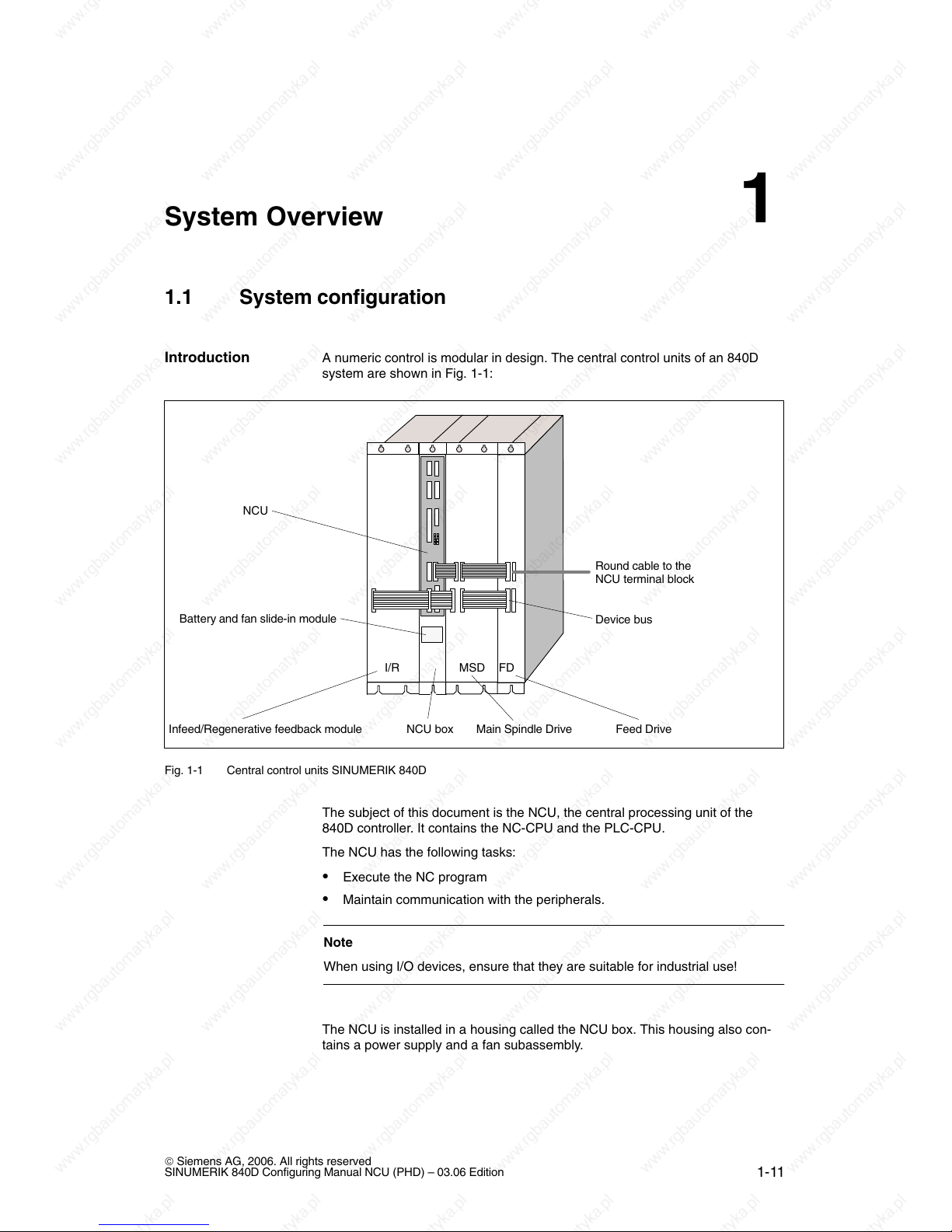
A numeric control is modular in design. The central control units of an 840D
system are shown in Fig. 1-1:
Battery and fan slide-in module
Infeed/Regenerative feedback module Feed DriveMain Spindle DriveNCU box
Round cable to the
NCU terminal block
NCU
Device bus
I/R FDMSD
Fig. 1-1 Central control units SINUMERIK 840D
The subject of this document is the NCU, the central processing unit of the
840D controller. It contains the NC-CPU and the PLC-CPU.
The NCU has the following tasks:
Execute the NC program
Maintain communication with the peripherals.
Note
When using I/O devices, ensure that they are suitable for industrial use!
The NCU is installed in a housing called the NCU box. This housing also con-
tains a power supply and a fan subassembly.
Introduction
1

03.06
1.1 System configuration
1-12
© Siemens AG, 2006. All rights reserved
SINUMERIK 840D Configuring Manual NCU (PHD) – 03.06 Edition
The NCU can communicate with the peripheral components via numerous inter-
faces. These are shown in Fig. 1-2 with their connections to the NCU and ex-
plained in more detail in Table 1-1:
NCU terminal block
IN OUT
X20 X21
Distribution
box
SIMATIC
S7-300
Handheld unit
Type B-MPI
X3
IM
X2
or
2x sensor
2x handwheel
PG / PC, e.g. Field PG
–X102
–X112
–X111
–X121
X130B
X130A
–X172
–X101
NCU
–X122
Cable
distribut
or
PROFIBUS DP I/Os
Reserved for service
X1
X2
X4
: Optional
MPI cable
*)
SIMODRIVE
components
MPI bus
for PCU / MCP (see Fig. 1-3)
*) MPI cable or MPI PG cable
Memory card
(PCMCIA)
Ä
Handheld terminal
HT 6
or
Mini-
handheld unit
4x digit. input
4x digit. output
Fig. 1-2 SINUMERIK 840D system overview
Connection
configuration
1 S
y
stem Overview
03.06
1.1 System configuration
1-13
© Siemens AG, 2006. All rights reserved
SINUMERIK 840D Configuring Manual NCU (PHD) – 03.06 Edition
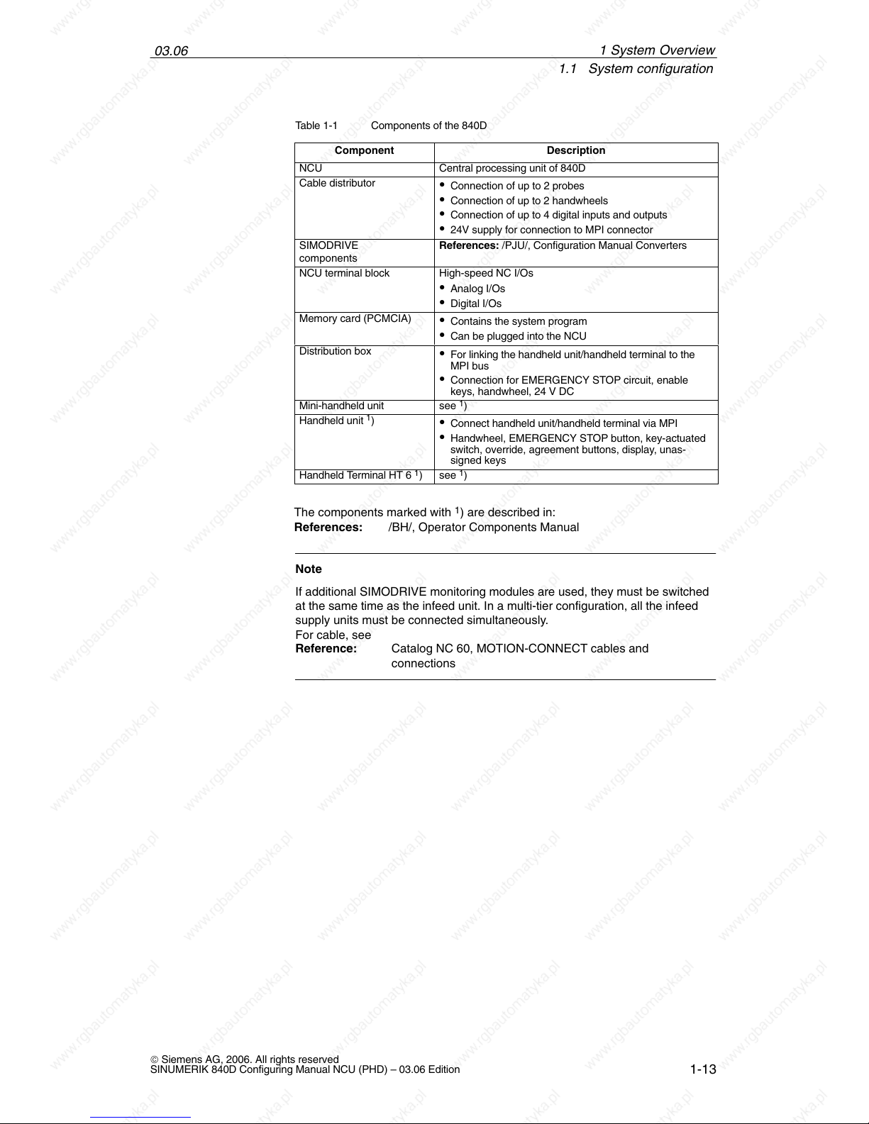
Table 1-1 Components of the 840D
Component
Description
NCU Central processing unit of 840D
Cable distributor
Connection of up to 2 probes
Connection of up to 2 handwheels
Connection of up to 4 digital inputs and outputs
24V supply for connection to MPI connector
SIMODRIVE
components
References: /PJU/, Configuration Manual Converters
NCU terminal block High-speed NC I/Os
Analog I/Os
Digital I/Os
Memory card (PCMCIA)
Contains the system program
Can be plugged into the NCU
Distribution box
For linking the handheld unit/handheld terminal to the
MPI bus
Connection for EMERGENCY STOP circuit, enable
keys, handwheel, 24 V DC
Mini-handheld unit see 1)
Handheld unit 1)
Connect handheld unit/handheld terminal via MPI
Handwheel, EMERGENCY STOP button, key-actuated
switch, override, agreement buttons, display, unas-
signed keys
Handheld Terminal HT 6 1) see 1)
The components marked with 1) are described in:
References: /BH/, Operator Components Manual
Note
If additional SIMODRIVE monitoring modules are used, they must be switched
at the same time as the infeed unit. In a multi-tier configuration, all the infeed
supply units must be connected simultaneously.
For cable, see
Reference: Catalog NC 60, MOTION-CONNECT cables and
connections
1 System Overview
03.06
1.1 System configuration
1-14
© Siemens AG, 2006. All rights reserved
SINUMERIK 840D Configuring Manual NCU (PHD) – 03.06 Edition
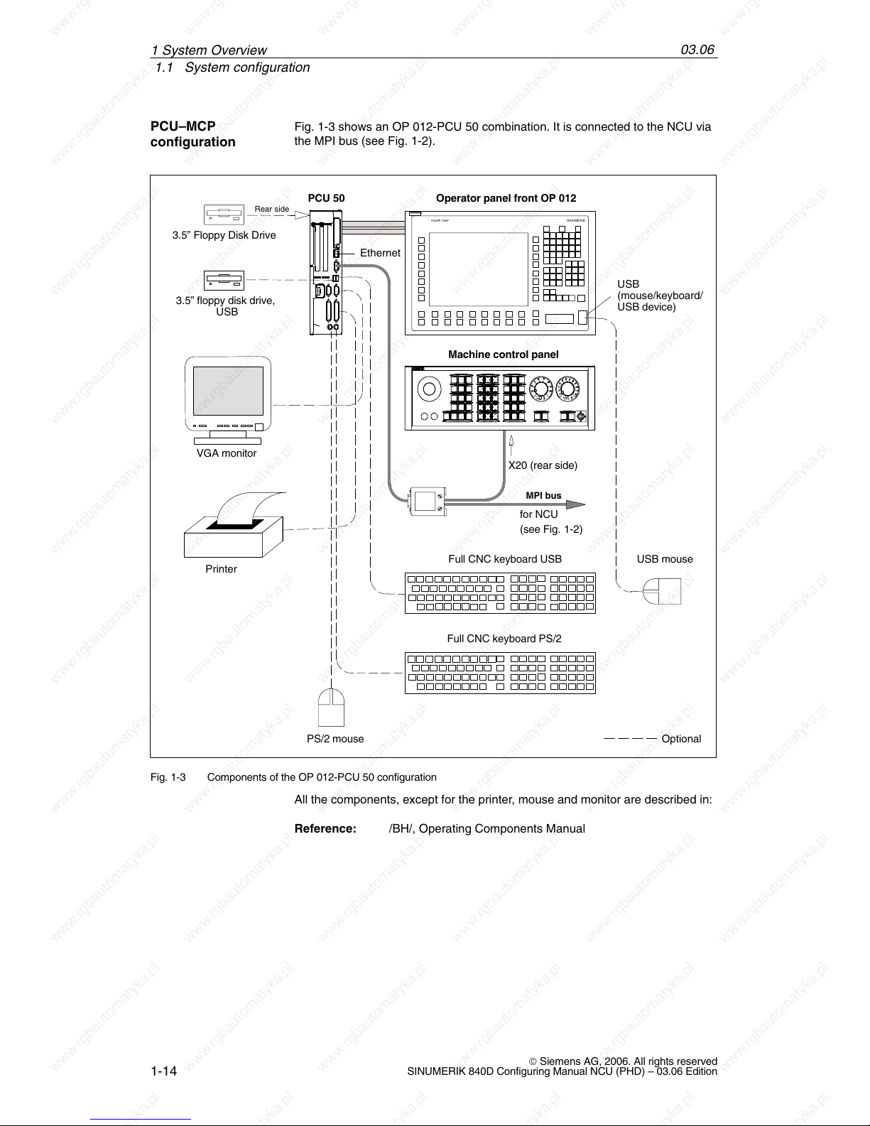
Fig. 1-3 shows an OP 012-PCU 50 combination. It is connected to the NCU via
the MPI bus (see Fig. 1-2).
Operator panel front OP 012PCU 50
Full CNC keyboard PS/2
3.5” Floppy Disk Drive
PS/2 mouse
VGA monitor
Printer
Machine control panel
X20 (rear side)
MPI bus
Ethernet
for NCU
(see Fig.
1-2)
Rear side
Optional
USB
(mouse/keyboard/
USB device)
* TEMP* POWER
SIEMENS
SINUMERIK
USB mouse Full CNC keyboard USB
3.5” floppy disk drive,
USB
Fig. 1-3 Components of the OP 012-PCU 50 configuration
All the components, except for the printer, mouse and monitor are described in:
Reference: /BH/, Operating Components Manual
PCU–MCP
configuration
1 S
y
stem Overview
03.06
1.1 System configuration
1-15
© Siemens AG, 2006. All rights reserved
SINUMERIK 840D Configuring Manual NCU (PHD) – 03.06 Edition
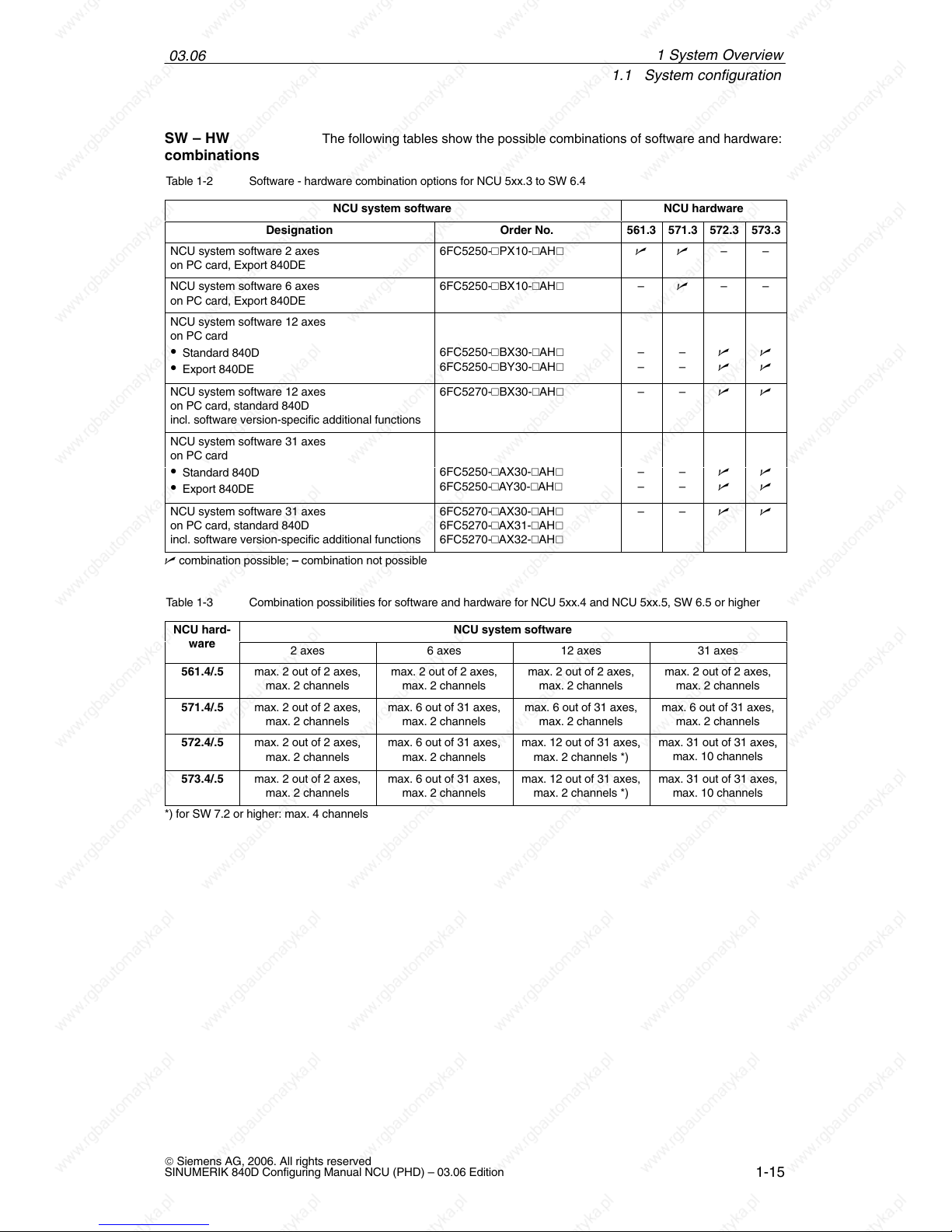
The following tables show the possible combinations of software and hardware:
Table 1-2 Software - hardware combination options for NCU 5xx.3 to SW 6.4
NCU system software
NCU hardware
Designation Order No. 561.3 571.3 572.3 573.3
NCU system software 2 axes
on PC card, Export 840DE
6FC5250-PX10-AH – –
NCU system software 6 axes
on PC card, Export 840DE
6FC5250-BX10-AH – – –
NCU system software 12 axes
on PC card
Standard 840D
Export 840DE
6FC5250-BX30-AH
6FC5250-BY30-AH
–
–
–
–
NCU system software 12 axes
on PC card, standard 840D
incl. software version-specific additional functions
6FC5270-BX30-AH – –
NCU system software 31 axes
on PC card
Standard 840D
Export 840DE
6FC5250-AX30-AH
6FC5250-AY30-AH
–
–
–
–
NCU system software 31 axes
on PC card, standard 840D
incl. software version-specific additional functions
6FC5270-AX30-AH
6FC5270-AX31-AH
6FC5270-AX32-AH
– –
combination possible; – combination not possible
Table 1-3 Combination possibilities for software and hardware for NCU 5xx.4 and NCU 5xx.5, SW 6.5 or higher
NCU hard-
NCU system software
ware
2 axes 6 axes 12 axes 31 axes
561.4/.5 max. 2 out of 2 axes,
max. 2 channels
max. 2 out of 2 axes,
max. 2 channels
max. 2 out of 2 axes,
max. 2 channels
max. 2 out of 2 axes,
max. 2 channels
571.4/.5 max. 2 out of 2 axes,
max. 2 channels
max. 6 out of 31 axes,
max. 2 channels
max. 6 out of 31 axes,
max. 2 channels
max. 6 out of 31 axes,
max. 2 channels
572.4/.5 max. 2 out of 2 axes, max. 6 out of 31 axes, max. 12 out of 31 axes, max. 31 out of 31 axes,
,
max. 2 channels
,
max. 2 channels
,
max. 2 channels *)
,
max. 10 channels
573.4/.5 max. 2 out of 2 axes,
max. 2 channels
max. 6 out of 31 axes,
max. 2 channels
max. 12 out of 31 axes,
max. 2 channels *)
max. 31 out of 31 axes,
max. 10 channels
*) for SW 7.2 or higher: max. 4 channels
SW – HW
combinations
1 S
y
stem Overview
03.06
1.2 Labels and stickers
1-16
© Siemens AG, 2006. All rights reserved
SINUMERIK 840D Configuring Manual NCU (PHD) – 03.06 Edition
1.2 Labels and stickers
In case of technical queries or service, please quote all data on the rating plate
to the local SIEMENS office responsible for your equipment.
One of the following labels is attached to the components and modules:
Example: Component number: 570 573.9001.00
Product version: B (last cross)
570 573.9001.00
E
D
C
SIEMENS
A
B
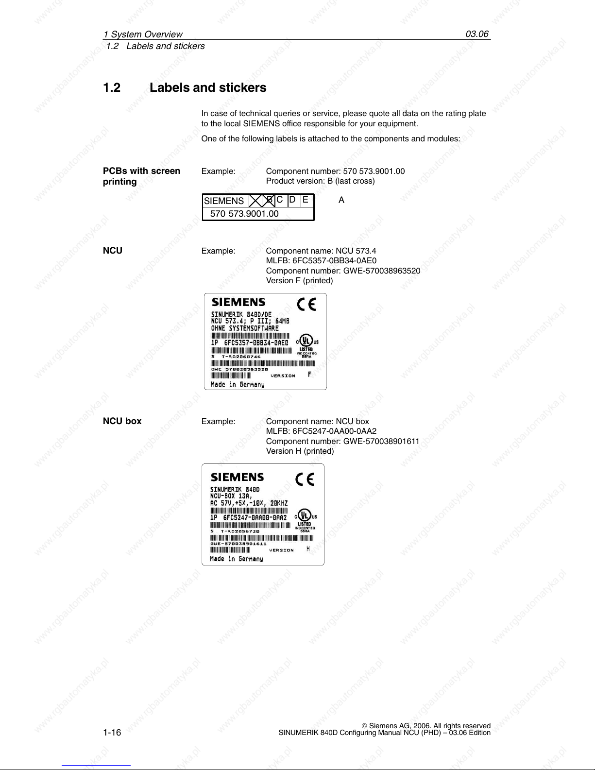
Example: Component name: NCU 573.4
MLFB: 6FC5357-0BB34-0AE0
Component number: GWE-570038963520
Version F (printed)
Example: Component name: NCU box
MLFB: 6FC5247-0AA00-0AA2
Component number: GWE-570038901611
Version H (printed)
PCBs with screen
printing
NCU
NCU box
1 S
y
stem Overview
03.06
1.3 Non-Siemens keyboards
1-17
© Siemens AG, 2006. All rights reserved
SINUMERIK 840D Configuring Manual NCU (PHD) – 03.06 Edition
1.3 Non-Siemens keyboards
When standard PC keyboards are used, ensure that they have a CE symbol
and correspond to industrial requirements. Otherwise, there may be problems
with the PC keyboard.
If you encounter problems, contact the relevant regional office.
Standard PC
keyboard
1 S
y
stem Overview

03.06
1.3 Non-Siemens keyboards
1-18
© Siemens AG, 2006. All rights reserved
SINUMERIK 840D Configuring Manual NCU (PHD) – 03.06 Edition
1 System Overview
Notes
2-19
© Siemens AG, 2006. All rights reserved
SINUMERIK 840D Configuring Manual NCU (PHD) – 03.06 Edition
Connection Conditions
2.1 Secondary electrical conditions
The controller is tested for compliance with the environmental conditions speci-
fied below. Fault-free operation is only ensured if:
These environmental conditions are maintained when storing, transporting
and operating the equipment,
Original components and spare parts are used. This applies in particular to
the use of specified cables and plug connectors,
The equipment has been correctly mounted/installed.
!
Danger
The equipment may not be commissioned until it has been clearly identified
that the machine in which the controller is installed is in full conformance with
the specifications in EC Machinery Directive 98/37/EC.
The connection conditions must be carefully maintained for the complete sys-
tem. Please contact your local Siemens office or representative for any assis-
tance.
Compliance with
the connection
conditions
Assistance and
support
2
03.06
2.1 Secondary electrical conditions
2-20
© Siemens AG, 2006. All rights reserved
SINUMERIK 840D Configuring Manual NCU (PHD) – 03.06 Edition
2.1.1 Power supply
!
Warning
The DC power supply is always referenced to ground and must be
generated by a safety transformer.
User interfaces must be powered via a DC power supply with safe isolation
to EN 61800–5–1.
In the case of supply cables > 10 m, protective elements must be fitted at
the device input in order to protect against lightning (surge voltage).
The DC power supply must be connected to the ground/shield of the NC for
EMC and/or functional reasons. For EMC reasons, this connection should
only be made at one point. As a rule, the connection is provided as
standard in the S7-300 I/Os. If this is not the case in exceptional
circumstances, the ground connection should be made to the grounding rail
of the NC cabinet; also refer to /EMC/ EMC Configuration Guideline.
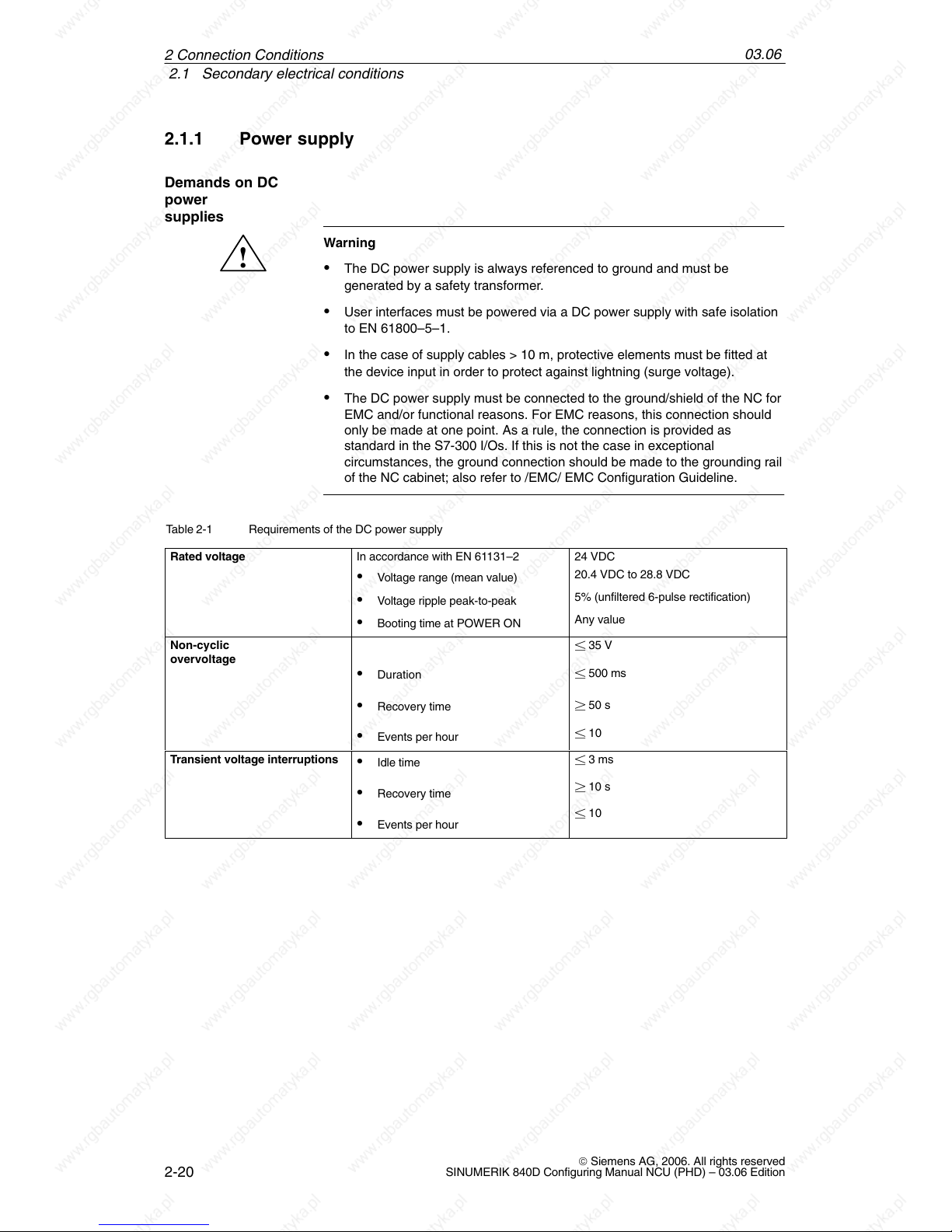
Table 2-1 Requirements of the DC power supply
Rated voltage
In accordance with EN 61131–2
Voltage range (mean value)
Voltage ripple peak-to-peak
Booting time at POWER ON
24 VDC
20.4 VDC to 28.8 VDC
5% (unfiltered 6-pulse rectification)
Any value
Non-cyclic
overvoltage
Duration
Recovery time
Events per hour
35 V
500 ms
50 s
10
Transient voltage interruptions
Idle time
Recovery time
Events per hour
3 ms
10 s
10
Demands on DC
power
supplies
2 Connection Conditions
03.06
2.1 Secondary electrical conditions
2-21
© Siemens AG, 2006. All rights reserved
SINUMERIK 840D Configuring Manual NCU (PHD) – 03.06 Edition
2.1.2 Safe isolation to EN 61800–5–1
The complete system includes user interfaces (UIs) and interfaces for servicing,
startup and maintenance.
UIs are all the interfaces that are freely accessible to the machine operator wi-
thout the need for tools or aids. These user interfaces are designed with safe
isolation to EN 61800–5–1.
!
Danger
The interfaces for servicing, start-up and maintenance purposes are provided
without safe isolation.
If necessary, these interfaces can be isolated safely using a supplementary
adapter (insulation voltage 230 V AC). Although these adapters are not included
in the Siemens scope of delivery, you can buy these parts from your local
dealer, who will be happy to advise you.
!
Danger
Safe isolation can only be ensured if the system configuration specified below
is strictly adhered to. When mounting additional components (e.g., S7-300 FM,
IP) with a UI, please make sure that the UI has basic insulation for at least
230 V AC.
End user
interfaces (UI)
Interfaces for
servicing, startup
and maintenance
2 Connection Conditions
03.06
2.1 Secondary electrical conditions
2-22
© Siemens AG, 2006. All rights reserved
SINUMERIK 840D Configuring Manual NCU (PHD) – 03.06 Edition
Basic insulation Safety isolation
G
3ph 400 V AC
N
Housing/shield
840D / 611 digital
1
2
3
4
10
4
4
5
6
11
S7-300 I/Os
MSTT/MCP
PCU
9
24 V
8
Person
G
7
10
11
Terminal
block
11
Motor
5
4
HHU/
HT 6
Distribution box
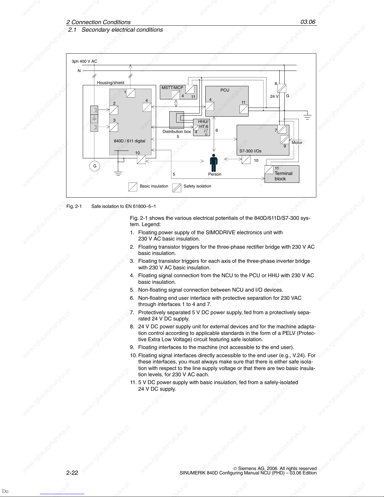
Fig. 2-1 Safe isolation to EN 61800–5–1
Fig. 2-1 shows the various electrical potentials of the 840D/611D/S7-300 sys-
tem. Legend:
1. Floating power supply of the SIMODRIVE electronics unit with
230 V AC basic insulation.
2. Floating transistor triggers for the three-phase rectifier bridge with 230 V AC
basic insulation.
3. Floating transistor triggers for each axis of the three-phase inverter bridge
with 230 V AC basic insulation.
4. Floating signal connection from the NCU to the PCU or HHU with 230 V AC
basic insulation.
5. Non-floating signal connection between NCU and I/O devices.
6. Non-floating end user interface with protective separation for 230 VAC
through interfaces 1 to 4 and 7.
7. Protectively separated 5 V DC power supply, fed from a protectively sepa-
rated 24 V DC supply.
8. 24 V DC power supply unit for external devices and for the machine adapta-
tion control according to applicable standards in the form of a PELV (Protec-
tive Extra Low Voltage) circuit featuring safe isolation.
9. Floating interfaces to the machine (not accessible to the end user).
10. Floating signal interfaces directly accessible to the end user (e.g., V.24). For
these interfaces, you must always make sure that there is either safe isola-
tion with respect to the line supply voltage or that there are two basic insula-
tion levels, for 230 V AC each.
11. 5 V DC power supply with basic insulation, fed from a safely-isolated
24 V DC supply.
2 Connection Conditions
03.06
2.1 Secondary electrical conditions
2-23
© Siemens AG, 2006. All rights reserved
SINUMERIK 840D Configuring Manual NCU (PHD) – 03.06 Edition
2.1.3 Grounding concept
The SINUMERIK 840D system consists of a number of individual components,
each of which must comply with the appropriate EMC and safety standards. The
individual system components are:
NCU box
Machine control panel MCP
Keyboard
Operator panels (operator panel front + PCU/TCU)
NCU terminal block
Distributor box and handheld unit
S7-300 I/O with IM 361 interface module
Single I/O module
The NCU box is a 50 mm wide cassette that is integrated into the infeed/regen-
erative feedback (I/RF) unit, FSD and MSD.
The individual modules are attached to a metal cabinet panel by means of
screws. Make sure that near the screws a low-impedance contact of the NCU
box with the cabinet wall can be made. Insulating paints at the contact point
must be removed. The electronic grounding points of the modules are intercon-
nected via the device and drive bus and at the same time conducted to the
X131 terminal of the I/RF module.
The ground and module ground M should be connected at the power supply
terminal of the IM 361. Further, for the EFP, “SHIELD” and “M24” must be con-
nected in connector X1.
2 Connection Conditions
03.06
2.1 Secondary electrical conditions
2-24
© Siemens AG, 2006. All rights reserved
SINUMERIK 840D Configuring Manual NCU (PHD) – 03.06 Edition
Operator panel
front
SL
SL
Power
electronics
Machine bed
Grounding bar
Central ground connection
conductor/protective
conductor
PA
G
G
PA
Gating
electronics
NCU
SL in the motor cable
Machine
control panel
S7-300 peripherals
/single I/O module
PA
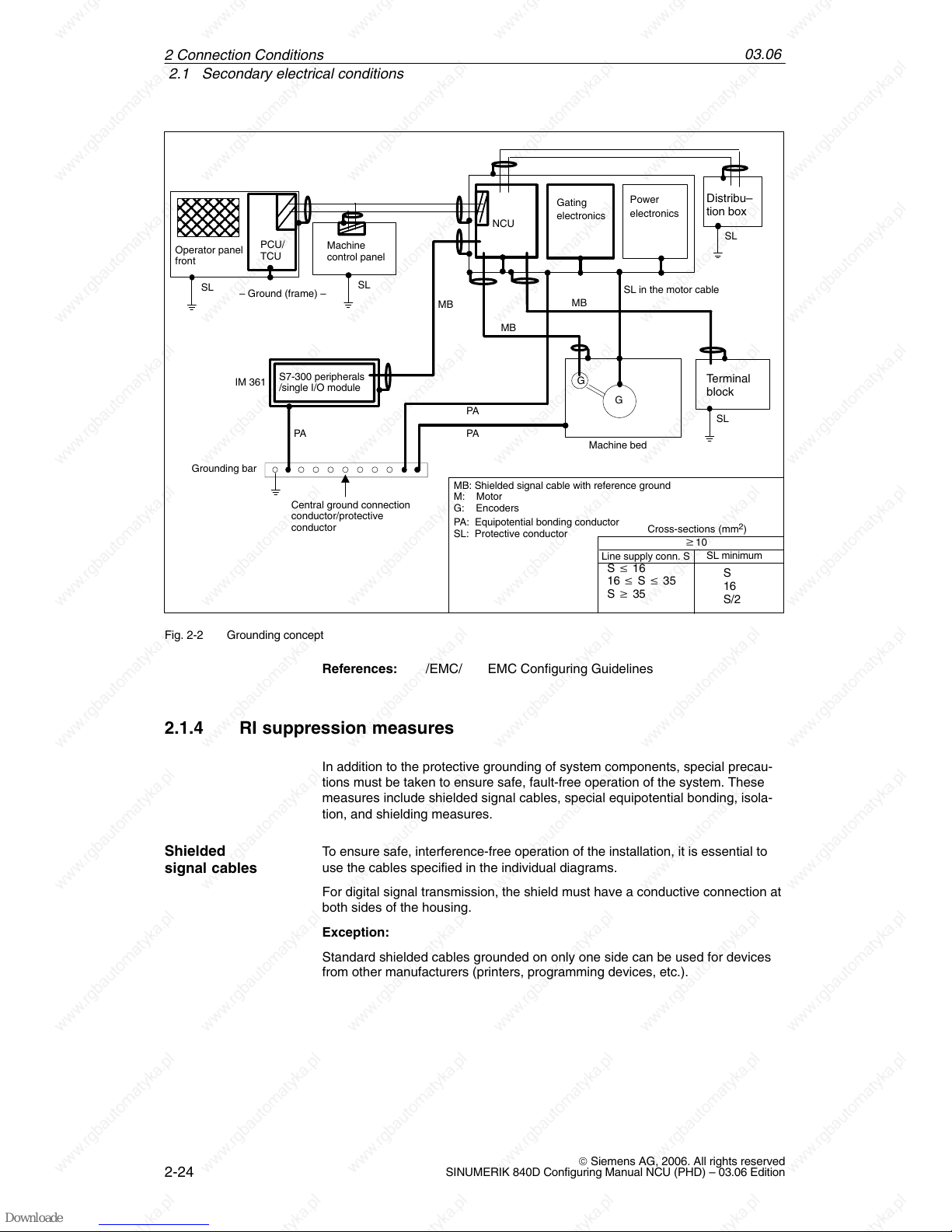
MB
MB: Shielded signal cable with reference ground
PA: Equipotential bonding conductor
SL: Protective conductor
M: Motor
G: Encoders
– Ground (frame) –
SL
Terminal
block
SL
Distribu–
tion box
Cross-sections (mm2)
w10
Line supply conn. S
SL minimum
S v 16
16 v S v 35
S w 35
S
16
S/2
MB
IM 361
PCU/
TCU
MB
Fig. 2-2 Grounding concept
References: /EMC/ EMC Configuring Guidelines
2.1.4 RI suppression measures
In addition to the protective grounding of system components, special precau-
tions must be taken to ensure safe, fault-free operation of the system. These
measures include shielded signal cables, special equipotential bonding, isola-
tion, and shielding measures.
To ensure safe, interference-free operation of the installation, it is essential to
use the cables specified in the individual diagrams.
For digital signal transmission, the shield must have a conductive connection at
both sides of the housing.
Exception:
Standard shielded cables grounded on only one side can be used for devices
from other manufacturers (printers, programming devices, etc.).
Shielded
signal cables
2 Connection Conditions
03.06
2.1 Secondary electrical conditions
2-25
© Siemens AG, 2006. All rights reserved
SINUMERIK 840D Configuring Manual NCU (PHD) – 03.06 Edition
These external devices may not be connected to the control during normal op-
eration. However, if the system cannot be operated without them, then the cable
shields must be connected at both ends. Furthermore, the external device must
be connected to the control via an equipotential bonding cable.
Definition:
Signal cables (example)
– Data cables (MPI, sensor cables, etc.)
– Binary inputs and outputs
– EMERGENCY OFF lines
Load cables (example)
– Low-voltage supply cables (230 V AC, +24 V DC etc.)
– Supply cables to contactors (primary and secondary circuit)
In order to achieve the best possible noise immunity of the complete system
(control, power module, machine), the following EMC measures must be care-
fully observed:
Signal cables and load cables must be routed at the greatest possible dis-
tance from one another.
If necessary, signal and load cables may cross one another (if possible, at
an angle of 90°), but must never be laid close or parallel to one another.
Only cables provided by the manufacturer should be used as signal cables
from and to the NCU.
Signal cables may not be routed close to strong external magnetic fields
(e.g. motors and transformers).
Pulse-carrying HC/HV cables must always be laid completely separately
from all other cables.
If signal lines cannot be routed a sufficient distance away from other cables,
they must be installed in grounded cable ducts (metal).
The clearance (interference injection area) between the following lines must
be kept to a minimum:
– Signal line and electrical circuit signal line (twisted)
– Signal line and associated equipotential bonding conductor
– Equipotential bonding conductor and PE conductor (routed together)
!
Important
For further notes on interference suppression measures and the connection of
shielded cables, please refer to
References: /EMC/ EMC Configuring Guidelines
Cable definitions
Rules for routing
cables
2 Connection Conditions
03.06
2.2 Climatic and mechanical environmental conditions
2-26
© Siemens AG, 2006. All rights reserved
SINUMERIK 840D Configuring Manual NCU (PHD) – 03.06 Edition
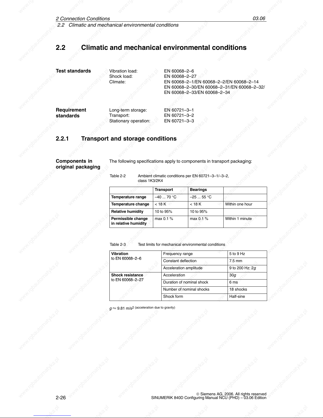
2.2 Climatic and mechanical environmental conditions
Vibration load: EN 60068–2–6
Shock load: EN 60068–2–27
Climate: EN 60068–2–1/EN 60068–2–2/EN 60068–2–14
EN 60068–2–30/EN 60068–2–31/EN 60068–2–32/
EN 60068–2–33/EN 60068–2–34
Long-term storage: EN 60721–3–1
Transport: EN 60721–3–2
Stationary operation: EN 60721–3–3
2.2.1 Transport and storage conditions
The following specifications apply to components in transport packaging:
Table 2-2 Ambient climatic conditions per EN 60721–3–1/–3–2,
class 1K3/2K4
Transport Bearings
Temperature range –40 ... 70 °C –25 ... 55 °C
Temperature change < 18 K < 18 K Within one hour
Relative humidity 10 to 95% 10 to 95%
Permissible change
in relative humidity
max 0.1 % max 0.1 % Within 1 minute
Table 2-3 Test limits for mechanical environmental conditions
Vibration
Frequency range 5 to 9 Hz
to EN 60068–2–6
Constant deflection 7.5 mm
Acceleration amplitude 9 to 200 Hz: 2g
Shock resistance
Acceleration 30g
to EN 60068–2–27
Duration of nominal shock 6 ms
Number of nominal shocks 18 shocks
Shock form Half-sine
g 9.81 m/s
2 (acceleration due to gravity)
Test standards
Requirement
standards
Components in
original packaging
2 Connection Conditions
03.06
2.2 Climatic and mechanical environmental conditions
2-27
© Siemens AG, 2006. All rights reserved
SINUMERIK 840D Configuring Manual NCU (PHD) – 03.06 Edition
Backup batteries must only be transported in the original packaging. No special
authorization is required to ship backup batteries. The lithium content is approxi-
mately 300 mg.
Note
The backup battery is classified as a hazardous substance, Class 9, in
accordance with the relevant air-freight transportation regulations.
!
Danger
Incorrect handling of backup batteries can lead to a risk of ignition, explosion
and combustion. The stipulations of EN 60086-4, in particular regarding
avoidance of mechanical or electrical tampering of any kind, must be complied
with.
For more information on handling batteries, see Chapter 8.1.
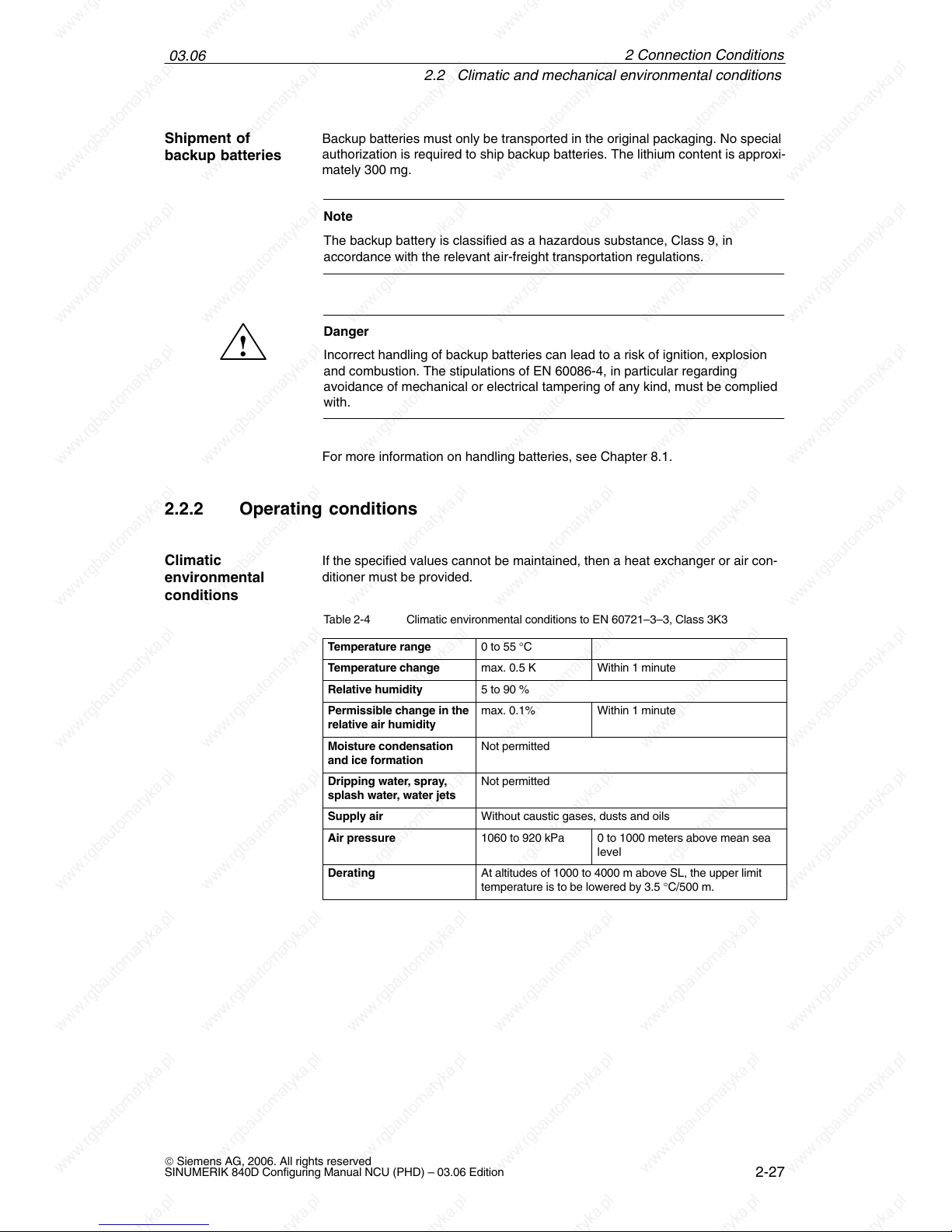
2.2.2 Operating conditions
If the specified values cannot be maintained, then a heat exchanger or air con-
ditioner must be provided.
Table 2-4 Climatic environmental conditions to EN 60721–3–3, Class 3K3
Temperature range
0 to 55 °C
Temperature change max. 0.5 K Within 1 minute
Relative humidity 5 to 90 %
Permissible change in the
relative air humidity
max. 0.1% Within 1 minute
Moisture condensation
and ice formation
Not permitted
Dripping water, spray,
splash water, water jets
Not permitted
Supply air Without caustic gases, dusts and oils
Air pressure 1060 to 920 kPa 0 to 1000 meters above mean sea
level
Derating At altitudes of 1000 to 4000 m above SL, the upper limit
temperature is to be lowered by 3.5 °C/500 m.
Shipment of
backup batteries
Climatic
environmental
conditions
2 Connection Conditions
03.06
2.2 Climatic and mechanical environmental conditions
2-28
© Siemens AG, 2006. All rights reserved
SINUMERIK 840D Configuring Manual NCU (PHD) – 03.06 Edition
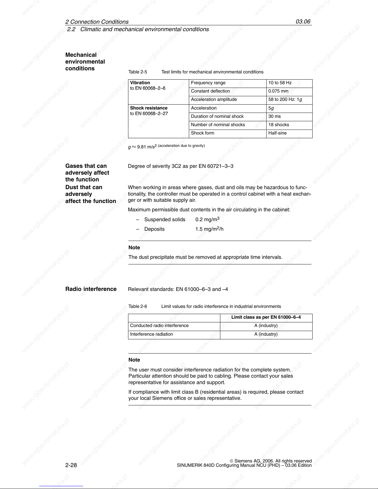
Table 2-5 Test limits for mechanical environmental conditions
Vibration
Frequency range 10 to 58 Hz
to EN 60068–2–6
Constant deflection 0.075 mm
Acceleration amplitude 58 to 200 Hz: 1g
Shock resistance
Acceleration 5g
to EN 60068–2–27
Duration of nominal shock 30 ms
Number of nominal shocks 18 shocks
Shock form Half-sine
g 9.81 m/s
2 (acceleration due to gravity)
Degree of severity 3C2 as per EN 60721–3–3
When working in areas where gases, dust and oils may be hazardous to func-
tionality, the controller must be operated in a control cabinet with a heat exchan-
ger or with suitable supply air.
Maximum permissible dust contents in the air circulating in the cabinet:
– Suspended solids 0.2 mg/m
3
– Deposits 1.5 mg/m2/h
Note
The dust precipitate must be removed at appropriate time intervals.
Relevant standards: EN 61000–6–3 and –4
Table 2-6 Limit values for radio interference in industrial environments
Limit class as per EN 61000–6–4
Conducted radio interference A (industry)
Interference radiation A (industry)
Note
The user must consider interference radiation for the complete system.
Particular attention should be paid to cabling. Please contact your sales
representative for assistance and support.
If compliance with limit class B (residential areas) is required, please contact
your local Siemens office or sales representative.
Mechanical
environmental
conditions
Gases that can
adversely affect
the function
Dust that can
adversely
affect the function
Radio interference
2 Connection Conditions
 Loading...