

Siemens SINUMERIK 808D, SINUMERIK 808D ADVANCED M, SINUMERIK 808D ADVANCED, SINUMERIK 808D ADVANCED T User Manual
Page 1
© Siemens AG 2017. All rights reserved
01/2017
1
SINUMERIK
SINUMERIK 808D, SINUMERIK 808D ADVANCED
Programming and Operating Manual (Manual Machine Plus
(MM+), Turning)
User Manual
Legal information
Warning notice system
This manual contains notices you have to observe in order to ensure your personal safety, as well as to prevent damage to property. The
notices referring to your personal safety are highlighted in the manual by a safety alert symbol, notices referring only to property damage
have no safety alert symbol. These notices shown below are graded according to the degree of danger.
DANGER
indicates that death or severe personal injury will result if proper precautions are not taken.
WARNING
indicates that death or severe personal injury may result if proper precautions are not taken.
CAUTION
indicates that minor personal injury can result if proper precautions are not taken.
NOTICE
indicates that property damage can result if proper precautions are not taken.
If more than one degree of danger is present, the warning notice representing the highest degree of danger will be used. A notice warning of
injury to persons with a safety alert symbol may also include a warning relating to property damage.
Qualified Personnel
The product/system described in this documentation may be operated only by
personnel qualified
for the specific task in accordance with
the relevant documentation, in particular its warning notices and safety instructions. Qualified personnel are those who, based on their
training and experience, are capable of identifying risks and avoiding potential hazards when working with these products/systems.
Proper use of Siemens products
Note the following:
WARNING
Siemens products may only be used for the applications described in the catalog and in the relevant technical documentation. If products
and components from other manufacturers are used, these must be recommended or approved by Siemens. Proper transport, storage,
installation, assembly, commissioning, operation and maintenance are required to ensure that the products operate safely and without any
problems. The permissible ambient conditions must be complied with. The information in the relevant documentation must be observed.
Page 2

Programming and Operating Manual (Manual Machine Plus (MM+), Turning)
2 01/2017
Preface
Applicable products
This manual is valid for the following control systems:
Control system
Software version
SINUMERIK 808D ADVANCED T (Turning)
SINUMERIK 808D ADVANCED M (Milling)
V4.7.4: PPU161.3/PPU160.2 with spindle/feed servo system
SINUMERIK 808D (Turning)
SINUMERIK 808D (Milling)
V4.7.4: PPU141.2 with feed servo system
Documentation components and target audience
End-user documentation
Target audience
Programming and Operating Manual (Turning) Programmers and operators of turning machines
Programming and Operating Manual (Milling)
Programmers and operators of milling machines
Programming and Operating Manual (ISO Turning/Milling)
Programmers and operators of turning/milling machines
Programming and Operating Manual (Manual Machine Plus
(MM+), Turning)
Programmers and operators of turning machines
Diagnostics Manual Mechanical and electrical designers, commissioning engi-
neers, machine operators, and service and maintenance
personnel
Manufacturer/service documentation
Target audience
Commissioning Manual Installation personnel, commissioning engineers, and ser-
vice and maintenance personnel
Function Manual
Mechanical and electrical designers, technical professionals
Parameter Manual
Mechanical and electrical designers, technical professionals
Service Manual Mechanical and electrical designers, technical profession-
als, commissioning engineers, and service and maintenance
personnel
Readme file
Third-party software - Licensing terms and copyright information
My Documentation Manager (MDM)
Under the following link you will find information to individually compile your documentation based on the Siemens content:
www.siemens.com/mdm
Standard scope
This manual only describes the functionality of the standard version. Extensions or changes made by the machine tool
manufacturer are documented by the machine tool manufacturer.
Technical support
Country
Hotline 1)
Further service contact information:
• Worldwide Web site:
https://support.industry.siemens.com/cs/ww/en/
• Chinese Web site:
http://www.siemens.com.cn/808D
Germany
+49 911 895 7222
China +86 400 810 4288
1)
You can find more hotline information at the worldwide Web site given above.
EC Declaration of Conformity
The EC Declaration of Conformity for the EMC Directive can be found on the Internet at
http://www.siemens.com/automation/service&support.
Here, enter the number "
67385845
" as the search term or contact your local Siemens office.
Page 3

Programming and Operating Manual (Manual Machine Plus (MM+), Turning)
01/2017
3
Table of contents
Preface ................................................................................................................................................................... 2
1 Fundamental safety instructions .............................................................................................................................. 4
1.1 General safety instructions ...................................................................................................................... 4
1.2 Industrial security .................................................................................................................................... 4
2 Turning on, Reference Point Approach .................................................................................................................... 5
3 Setting-up ............................................................................................................................................................... 6
3.1 Measuring tools ....................................................................................................................................... 6
3.2 Limit stops ............................................................................................................................................... 8
3.2.1 Setting and activating/deactivating limit stops ......................................................................................... 9
3.2.2 Turning against a stop ........................................................................................................................... 11
3.3 Setting the workpiece zero .................................................................................................................... 12
4 Manual machining ................................................................................................................................................. 13
4.1 Fundamentals of manual machining ...................................................................................................... 13
4.2 Display and operator control options in the main screen ....................................................................... 13
4.2.1 Toggling the display............................................................................................................................... 16
4.2.2 Machining with the handwheels ............................................................................................................. 18
4.2.3 Setting the increment weighting for the handwheel ............................................................................... 18
4.2.4 Machining with axis direction switch ...................................................................................................... 18
4.2.5 Spindle advance/reverse ....................................................................................................................... 19
4.2.6 Tool change ........................................................................................................................................... 19
4.2.7 Changing the feedrate/spindle value ..................................................................................................... 20
4.2.8 Changing the feedrate/spindle type ....................................................................................................... 21
4.2.9 Change the speed limitation for constant cutting rate ............................................................................ 22
4.3 Manual machining with machining types ............................................................................................... 23
4.3.1 Axis-parallel traversal ............................................................................................................................ 23
4.3.2 Manual taper turning.............................................................................................................................. 24
4.3.3 Manual radius turning ............................................................................................................................ 25
4.3.3.1 Radius turning type A ............................................................................................................................ 27
4.3.3.2 Radius turning type B ............................................................................................................................ 27
4.3.3.3 Radius turning type C ............................................................................................................................ 28
4.4 Manual machining using cycles (functions) ........................................................................................... 28
4.4.1 Principle operating sequence ................................................................................................................ 28
4.4.2 General parameters............................................................................................................................... 31
4.4.3 Manual drilling centered ........................................................................................................................ 32
4.4.4 Manual thread tapping ........................................................................................................................... 35
4.4.5 Manual grooving/parting ........................................................................................................................ 37
4.4.5.1 Groove cycle - single ............................................................................................................................. 37
4.4.5.2 Groove cycle - multiple .......................................................................................................................... 39
4.4.5.3 Extended grooving ................................................................................................................................ 41
4.4.5.4 Multiple extended grooving .................................................................................................................... 44
4.4.6 Manual thread cutting ............................................................................................................................ 45
4.4.6.1 Thread cutting ....................................................................................................................................... 46
4.4.6.2 Thread recutting .................................................................................................................................... 49
4.4.7 Roughing cycles .................................................................................................................................... 51
4.4.7.1 Roughing cycle A .................................................................................................................................. 52
4.4.7.2 Roughing cycle B .................................................................................................................................. 55
4.4.7.3 Roughing cycle C .................................................................................................................................. 57
4.4.7.4 Roughing cycle D ................................
.................................................................................................. 59
4.
4.7.5 Roughing cycle E .................................................................................................................................. 61
4.4.7.6 Roughing cycle F ................................................................................................................................... 63
4.4.7.7 Roughing cycle, free contour ................................................................................................................. 65
4.4.7.8 Execute a roughing cycle ...................................................................................................................... 68
5 Machining the machining step program manually ................................................................................................... 69
5.1 Tool change in the machining step program .......................................................................................... 73
Page 4
Programming and Operating Manual (Manual Machine Plus (MM+), Turning)
4 01/2017
5.2 Teach In ................................................................................................................................................ 75
5.3 Simulate machining ............................................................................................................................... 77
5.4 Executing the machining step program ................................................................................................. 78
6 Messages .............................................................................................................................................................80
1
Fundamental safety instructions
1.1
General safety instructions
WARNING
Danger to life if the safety instructions and residual risks are not observed
If the s
afety instructions and residual risks in the associated hardware documentation are not observed, accidents involving
severe injuries or death can occur.
• Observe the safety instructions given in the hardware documentation.
•
Consider the residual risks for the risk evaluation.
WARNING
Danger to life or malfunctions of the machine as a result of incorrect or changed parameterization
As a result of incorrect or changed parameterization, machines can malfunction, which in turn can lead to injuries or death.
• Protect the parameterization (parameter assignments) against unauthorized access.
•
Respond to possible malfunctions by applying suitable measures (e.g. EMERGENCY STOP or EMERGENCY OFF).
1.2
Industrial security
Note
Industrial security
Siemens provides products and solutions with industrial secur
ity functions that support the secure operation of plants,
systems, machines and networks.
In order to protect plants, systems, machines and networks against cyber threats, it is necessary to implement
– and
continuously maintain
– a holistic, state-of-the-
art industrial security concept. Siemens products and solutions only represent
one component of such a concept.
The customer is responsible for preventing unauthorized access to its plants, systems, machines and networks. Systems,
machines and components should only be connected to the enterprise network or the internet if and to the extent necessary
and with appropriate security measures (e.g. use of firewalls and network segmentation) in place.
Additionally, Siemens’ guidance on appropriate security measures should be taken into account. For more information about
industrial security, please visit:
Industrial security (
http://www.siemens.com/industrialsecurity).
Siemens’ products and solutions
undergo continuous development to make them more secure. Siemens strongly
recommends to apply product updates as soon as available and to always use the latest product versions. Use of product
versions that are no longer supported, and failure to apply lat
est updates may increase customer’s exposure to cyber
threats.
To stay informed about product updates, subscribe to the Siemens Industrial Security RSS Feed at:
Industrial security (
http://www.siemens.com/industrialsecurity).
Page 5
Programming and Operating Manual (Manual Machine Plus (MM+), Turning)
01/2017
5
WARNING
Danger to life as a result of unsafe operating states resulting from software manipulation
Software manipulations (e.g. viruses, trojans, malware or worms) can cause unsafe operating states in your system that
may lead to death, serious injury, and property damage.
• Keep the software up to date.
• Incorporate the automation and drive components into a holistic, state-of-the-art industrial security concept for the
installation or machine.
• Make sure that you include all installed products into the holistic industrial security concept.
• Protect files stored on exchangeable storage media from malicious software by with suitable protection measures, e.g.
virus scanners.
2
Turning on, Reference Point Approach
Note
If the controller has already been preconfigured
to Manual Machine Plus (MM+) by the machine manufacturer, the desired
operating area is activated once the controller has been started up.
This operating area runs only in SIEMENS mode instead of ISO mode.
Operating sequence
Note that if MD1105 = 1, after power on, the control system automatically opens the main screen for MM+.
1. Press this key on the machine control panel to open the "JOG" window.
Page 6
Programming and Operating Manual (Manual Machine Plus (MM+), Turning)
6 01/2017
2. Press this softkey to open the MM+ operating area.
3. If the axes have not approached the reference point, press this key to change to the
"REF.POINT" window for reference point approaching operation; otherwise, skip this step.
For more information on refer
ence point approaching, see Chapter "Switching on and refer-
encing
" of the SINUMERIK 808D/SINUMERIK 808D ADVANCED Programming and Oper-
ating Manual (Turning).
4. Press this softkey to exit the operating area.
Note
The pictures in the parameterization screenforms depend on the
setting of the machine data by the machine manufacturer,
that is, display of the tool position before or behind the center of rotation with regards to the turret head.
3
Setting-up
3.1
Measuring tools
Functionality
You can measure tools manually in the MM+ operating area. In this case, the manual tool measurement function accesses
the tool list data.
Note
To access the tool list, proceed as follows:
→
Page 7
Programming and Operating Manual (Manual Machine Plus (MM+), Turning)
01/2017
7
NOTICE
Tool breakage or workpiece damage
An uncalibrated or incorrectly calibrated tool can lead to dimensional errors or to incorrect cutting values. If the values
entered are very different from the actual tool values, there is a risk that the tool may break or the mechanism or workpiece
may be damaged.
Requirement
Load the tool beforehand or enter the tool number in the "T" field. After confirming the input, a dialog will prompt you to press
the following hardkey. If this key is pressed, the tool will be changed.
Note
First approach a machine position whe
re the tool change can be performed without danger.
Operating sequence
Proceed as follows to measure the tool for the X axis of the loaded turning tool.
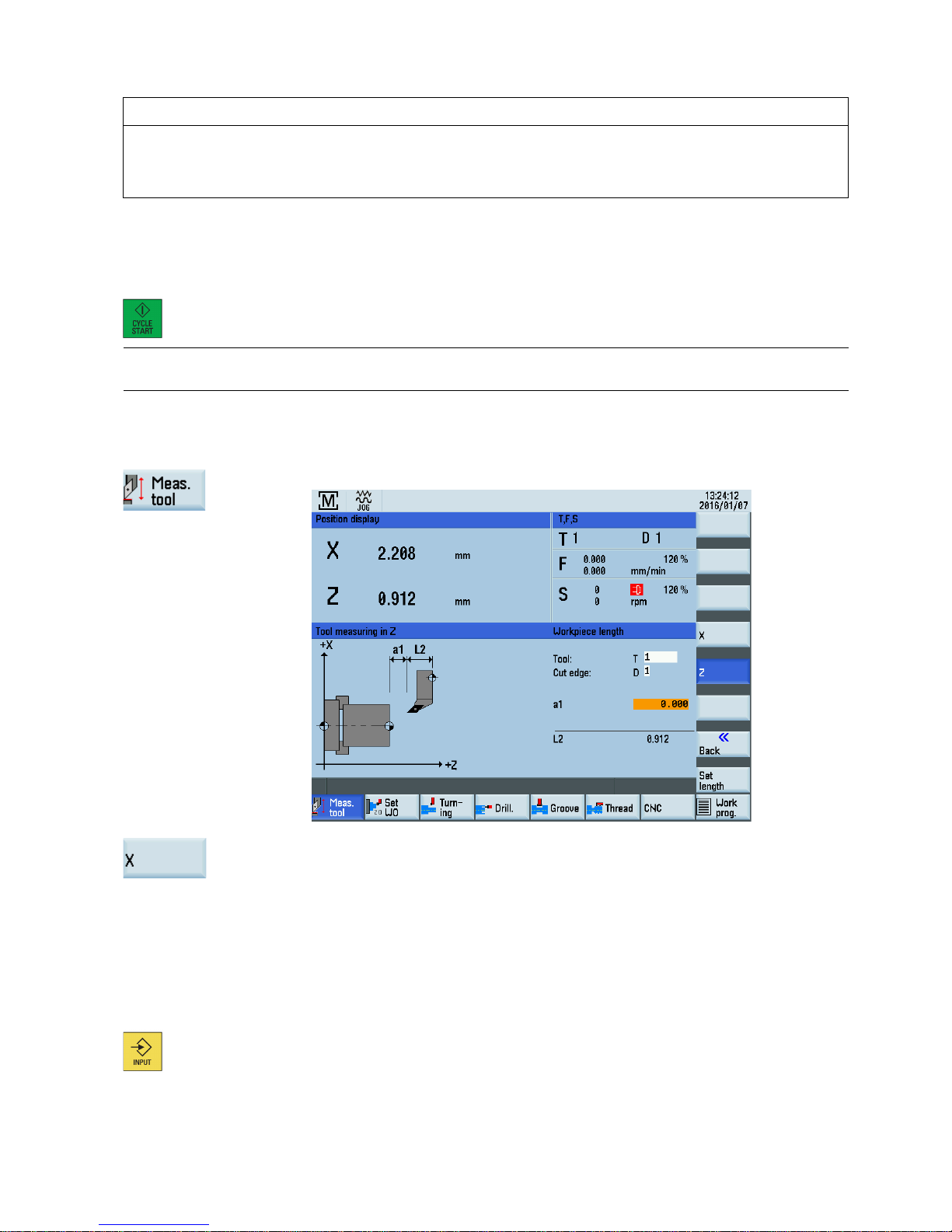
1. Press this softkey. The following screen appears.
2. Press this softkey.
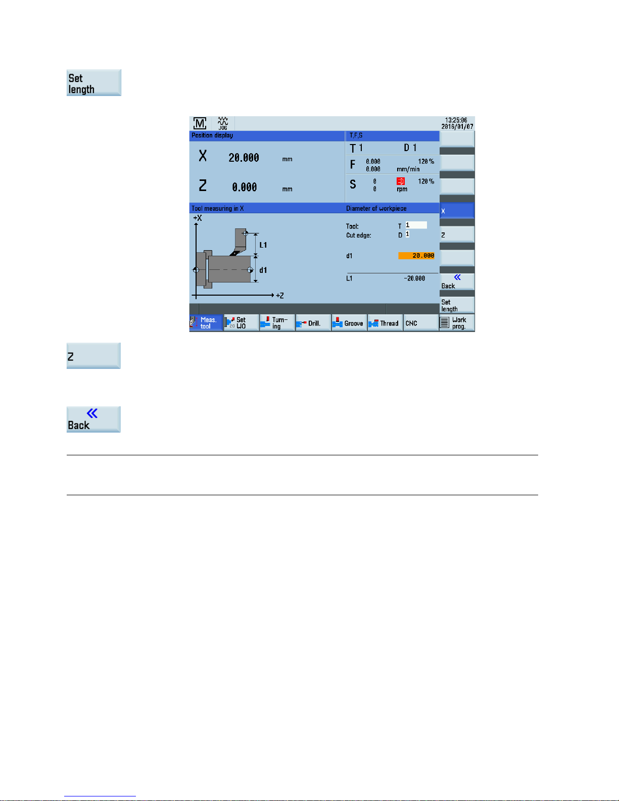
The screen for measuring the X axis (L1) appears.
3. Check that the current tool number appears in the display fiel
d for the tool, since the calibra-
tion operation will relate to this tool.
4.
Carefully "scratch" a workpiece by an X handwheel infeed when the spindle is turning.
5. Move the slide slightly (without changing the X position) along the Z axis (longitudin
al turn-
ing) with the handwheel.
6.
Switch the spindle off.
7.
Enter the diameter measured on the workpiece in entry field "d1".
8. Accept the value by pressing this hardkey.
The controller then automatically calculates the corresponding tool offset (in the radius) and
displays this
as value "L1" in the screen form.
Page 8
Programming and Operating Manual (Manual Machine Plus (MM+), Turning)
8 01/2017
9. Press this softkey.
The modified tool offset for the selected tool is applied in the X axis. Provided that the
"scratch position" in the X axis has not been moved, the measured diameter is now di
s-
played as the actual position in the position display
of the tool measurement screen.
10. Press this softkey.
The scr
een for measuring the Z axis appears.
The Z axis can be measured in the same way as the X axis.
When measuring the tool in the Z axis, you may define a distance between the workpiece
and the turning tool tip in input field "a1" to avoid surface damage on the workpiece.
11. Press this so
ftkey to return to the main screen for MM+.
Note
New offset settings lost
If you exit the screen form in step 8, the new offset will not take effect.
3.2
Limit stops
Functionality
Limit stops are used to stop the axes in a specific position.
If an axis stops in the limit stop position, it cannot be moved again until the triggering limit stop is reset.
By setting the limit stops, in the MM+ operating area, it is possible to turn simple shoulders (including tapers) without the
need for any further cycle parameterization.
Supplementary conditions
● The limit stop position is always an absolute dimension, which in turn always corresponds to the position in the absolute
actual value display on the MM+ interface. A relative limit stop position is not possible.
● A limit stop position can be entered/accepted only when the axes are stationary; otherwise, an error message appears.
Page 9
Programming and Operating Manual (Manual Machine Plus (MM+), Turning)
01/2017
9
3.2.1
Setting and activating/deactivating limit stops
Functionality
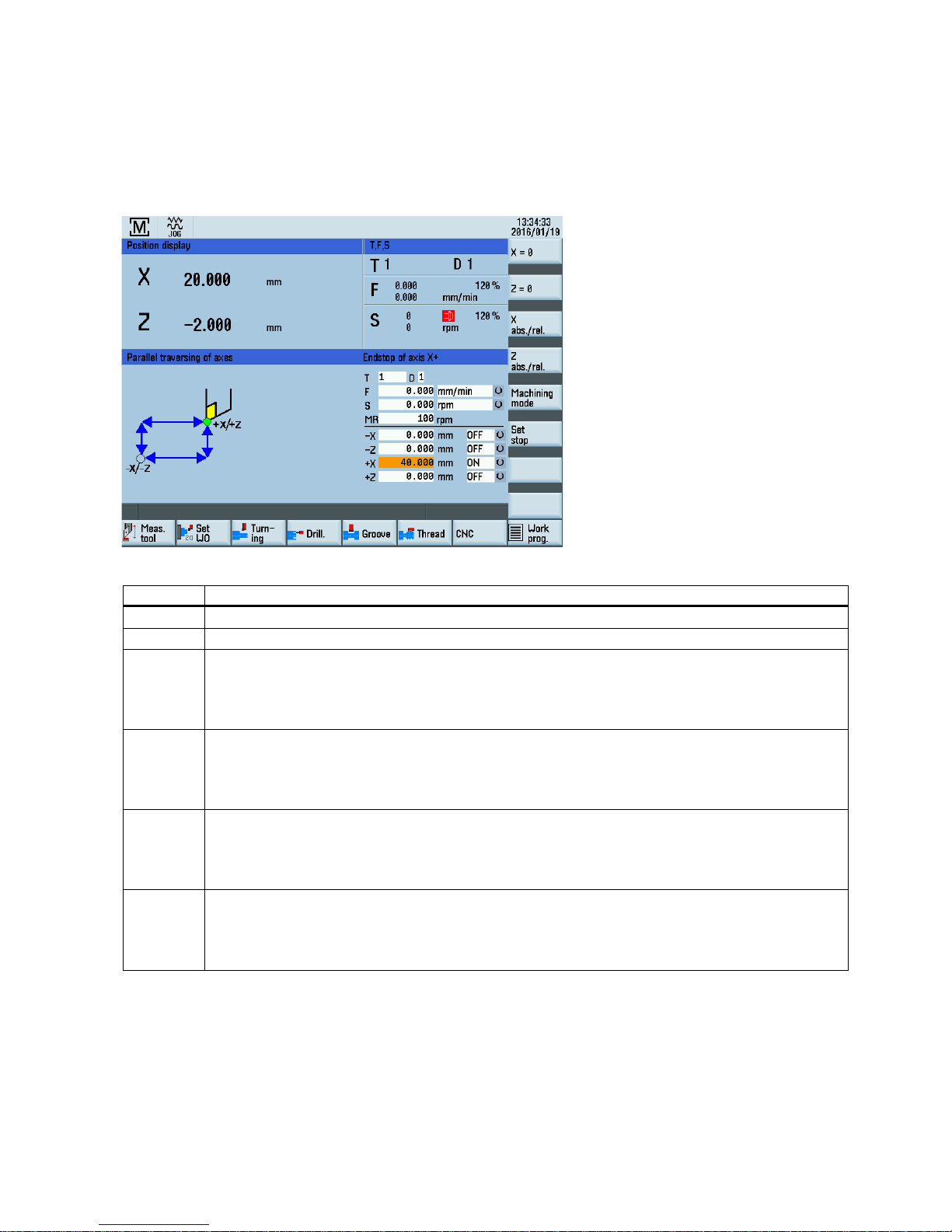
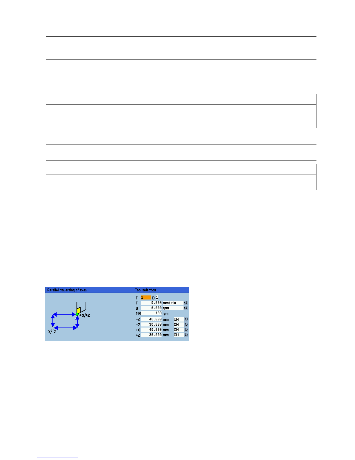
In the main screen of MM+, limit stops can be entered into the input fields "-X/-Z/+X/+Z".
In the following screen, the cursor is located in the desired input field (with an orange background).
Parameter
Parameter
Description
ON
The limit stop is activated.
OFF
The limit stop is deactivated.
- X Negative absolute position of the limit stop of the X axis.
The axis stops automatically when both of the following are met:
• The limit stop is active.
•
The specified axis traverses in the negative direction and reaches the absolute limit stop position.
+X Positive absolute position of the limit stop of the X axis.
The axis stops automatically when both of the following are met:
• The limit stop is active.
•
The specified axis traverses in the positive direction and reaches the absolute limit stop position.
-Z Negative absolute position of the limit stop of the Z axis.
The axis stops automatically when both of the following are met:
• The limit stop is active.
•
The specified axis traverses in the negative direction and reaches the absolute limit stop position.
+Z Positive absolute position of the limit stop of the Z axis.
The axis stops automatically when both of the following are met:
• The limit stop is active.
•
The specified axis traverses in the positive direction and reaches the absolute limit stop position.
Page 10
Programming and Operating Manual (Manual Machine Plus (MM+), Turning)
10 01/2017
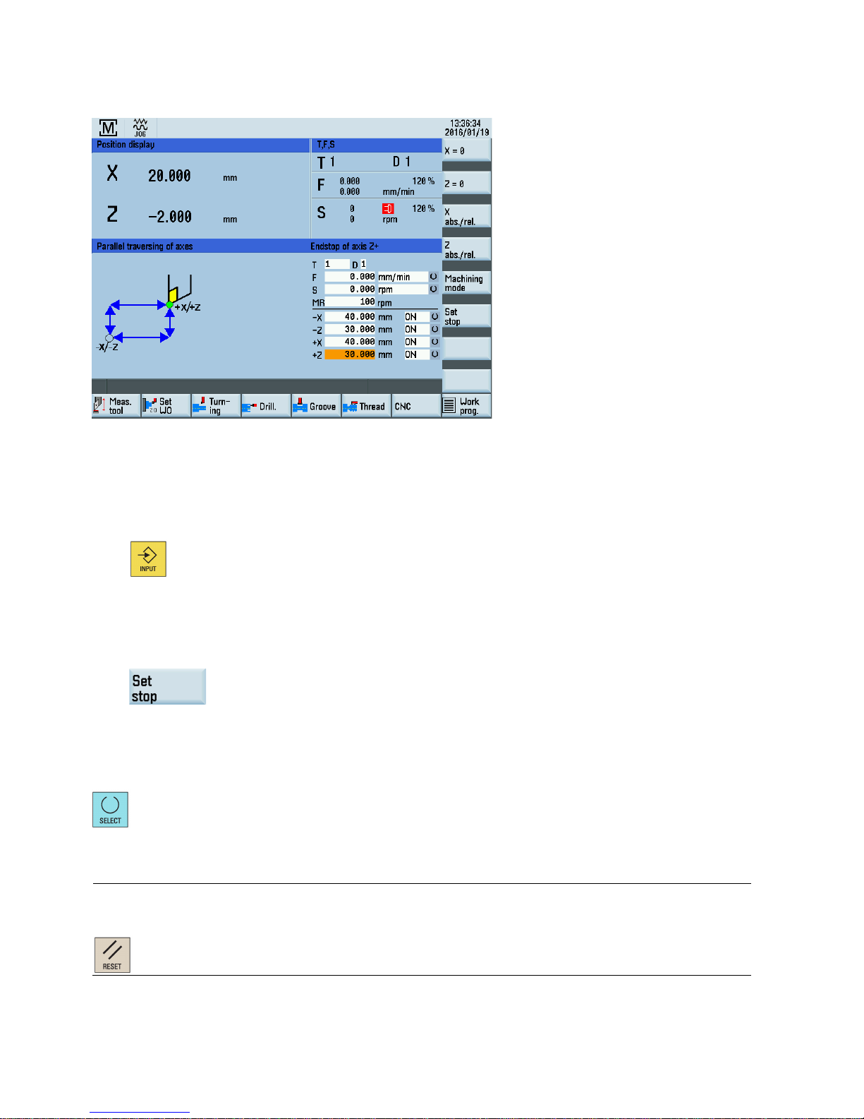
All of the limit stops are set in the following screen.
Operating sequences
You can use the following methods to enter a limit stop position:
● Direct position entry:
– Select the input field of the relevant limit stop with the cursor keys.
– Now use the numeric keys to enter the absolute position you require.
– Press the above hardkey to accept the value.
● Accepting the current actual position:
– Select the input field of the relevant limit stop with the cursor keys.
– Traverse to the required position using the axis direction switch (for example, <-Z> or <+X/-X/+Z>).
– Press the above softkey.
The current actual position of the relevant axis is transferred to the input field.
Activating/disabling limit stops
The limit stops are activated/deactivated individually using the above hardkey.
Here, you can select ON or OFF.
Note
After activating a limit stop, set MD201
52[59] = 1 to retain the current setting even after you press the following key.
Page 11

Programming and Operating Manual (Manual Machine Plus (MM+), Turning)
01/2017
11
3.2.2
Turning against a stop
Example:
The following example explains the operating principle of limit stops using the axis direction keys.
You can also use the handwheel to perform the machining operation.
Task
The following shoulder with a finishing allowance of 0.2 mm must be turned:
● 100 mm in the Z direction
● 50 mm final diameter in the X direction
The end face starts at 0 mm in the Z direction. The blank diameter is 70 mm.
Operating sequences for infeeding to stop
1. Position the axes in front of the workpiece (for example, X +75 mm/Z +5 mm).
2. Check the machining technology data.
3. Set the following limit stops:
– -X at 50.4 mm
– -Z at -99.8 mm (due to finishing allowance)
– +Z at +5 mm
4. Delete the limit stop for +X; it is not required.
5. Start the spindle.
6. Using the handwheel, infeed to the 1st depth of cut in the X direction.
7. Start machining in the Z axis in the negative direction using the axis direction switch.
When the limit stop position in Z -99.8 mm is reached, the Z axis stops automatically.
A message is displayed, saying that limit stop -Z is reached.
8. Switch-out the axis direction switch.
9. Using the handwheel, retract the tool from the workpiece in the X direction.
10. Using the axis direction switch and rapid traverse override, move the tool in a positive Z direction towards the workpiece
until the axis stops.
A message is displayed, saying that limit stop +Z is reached.
11. Switch-out the axis direction switch.
12. Using the handwheel, infeed to the next depth of cut in the X direction.
13. Start machining in the Z axis in the negative direction using the axis direction switch.
Repeat the procedure until the depth of rough cut is reached.
A message is displayed as the tool is fed in, saying that limit stop -X is reached.
Once this cut has been completed, adjust the limit stops to the finished dimension, provided that the axes are positioned
in front of the workpiece.
Operating sequences for adjusting to finished dimension
1. Adjust the limit stops to the finished dimension: -X to 50.0 mm/-Z to -100.0 mm
2. Using the handwheel, infeed in the X direction until a message saying that limit stop -X is reached appears.
3. Start machining in the Z axis in the negative direction using the axis direction switch.
When the limit stop position in Z -100.0 mm is reached, the Z axis stops automatically.
A message is displayed, saying that limit stop -Z is reached.
4. Switch-out the axis direction switch in the Z direction and start in the positive X direction (finishing the end face).
5. Switch-out the axis direction switch in the X direction as soon as the tool tip leaves the workpiece.
Page 12
Programming and Operating Manual (Manual Machine Plus (MM+), Turning)
12 01/2017
3.3
Setting the workpiece zero
Functionality
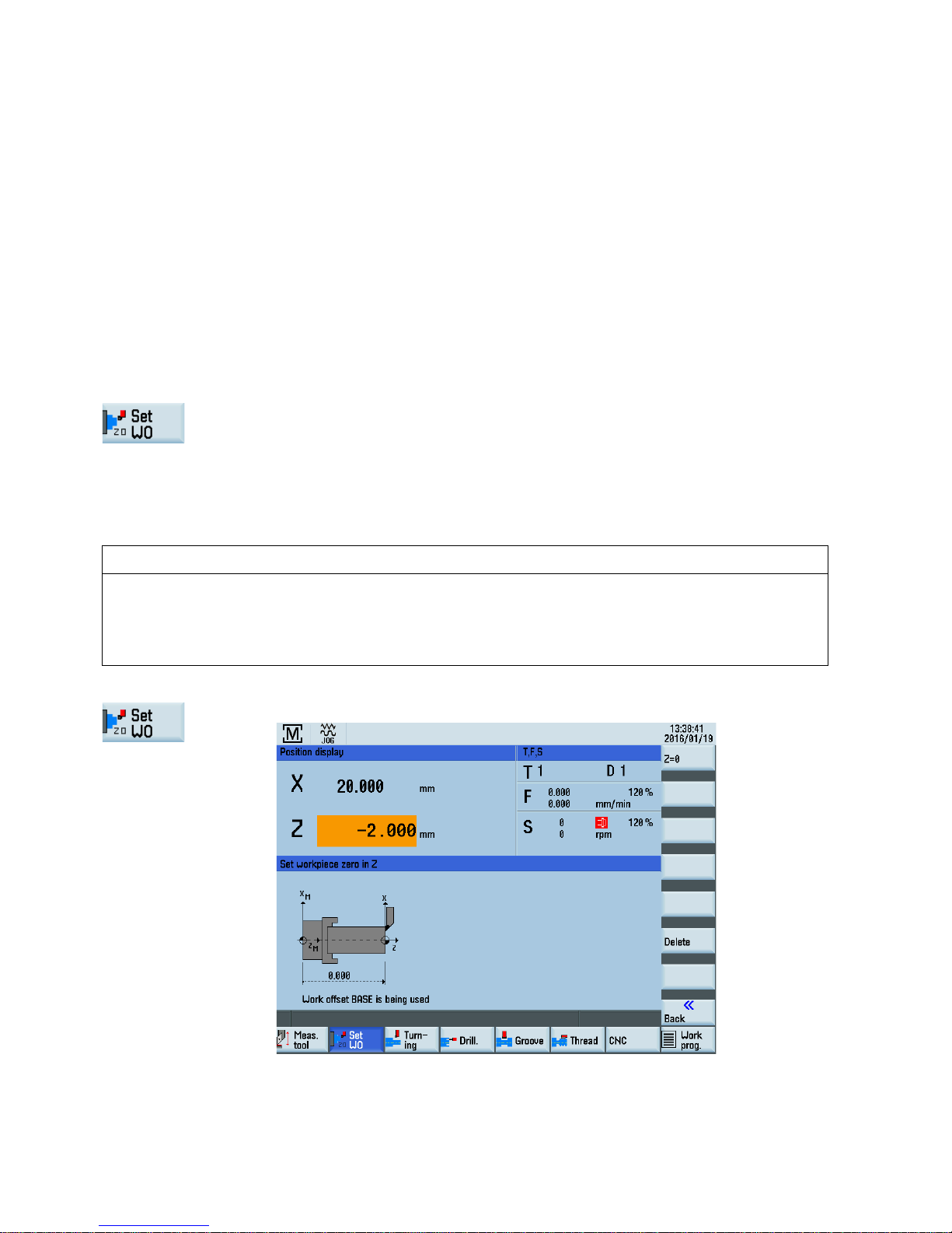
The function of setting the workpiece zero can be used to specify the reference point for machining the workpiece.
Typical application/procedure:
1. Parameterize all the machining steps (cycles) for the workpiece in relation to a "virtual zero point" (for example, an end
face).
2. Clamp the blank.
3. Scratch the relevant surface which corresponds to the "virtual zero point".
4. Use the function of setting the workpiece zero to adapt the workpiece coordinate system to the parameterized machining
operation.
Make sure that the axis does not exit from the approached position.
Additional information
The following operations are performed automatically when
you select this softkey:
•
The work offset is automatically calculated according to the current axis position in the
longitudinal axis (Z), entered in the control system memory as the basic offset and activated.
•
This will also set the position displayed for the longitudinal axis (Z) to 0.000, as this always
corresponds to the workpiece coordinate system.
•
If the workpiece zero is reset, the value "0.000" will be automatically entered in the control
system memory as the basic offset. The workpiece coordinate system display will change to
reflect this.
NOTICE
Setting the workpiece zero carefully
Setting the workpiece zero affects the absolute machining position of all machining steps that have been parameterized in
the controller. All machining steps will now be performed in relation to the zero point that has just been set.
Setting/resetting the workpiece zero without due care and attention can result in serious damage to the tool, workpiece or
machine.
Operating sequences
1. Press this softkey in the main screen for MM+.
This screen displays the currently program
med Z value of the basic work offset.
Page 13

Programming and Operating Manual (Manual Machine Plus (MM+), Turning)
01/2017
13
2. Press this softkey to set the workpiece zero.
The workpiece coordinate system of the longitudinal axis (Z) displays the value "0.000". The
required work offset is computed automatically and stored in the appropriate place in the co
n-
trol system.
3. Press this softkey to reset t
he work offset that is currently stored on the control system. The
value "0.000" is entered in the basic offset memory location. However, all other offsets and the
active tool offset remain unchanged.
4
Manual machining
4.1
Fundamentals of manual machining
Functionality
You can perform the following machining operations manually:
● Axis-parallel traversal
● Taper turning
● Radius turning
● Drilling - centered
● Tapping
● Groove cycles/Expan. groove
● Thread cutting
● Rough turning of contours
Fundamentals
The following operations must be performed before manual machining can proceed:
● Axes referenced
● Tools measured
● Limit stops set
● Set workpiece zero point
4.2
Display and operator control options in the main screen
Functionality
Note
If the controller has already been preconfigured
to MM+ by the machine manufacturer, the desired operating area is
activated once the controller has been started up. If you have not yet executed a reference point approach, you will be in
"REF.POINT" operating mode after start
-up.
You can reference the a
xes in the Siemens standard user interface as well as in the operating area MM+.
Page 14

Programming and Operating Manual (Manual Machine Plus (MM+), Turning)
14 01/2017
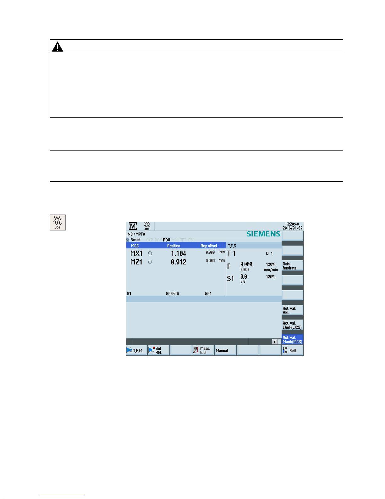
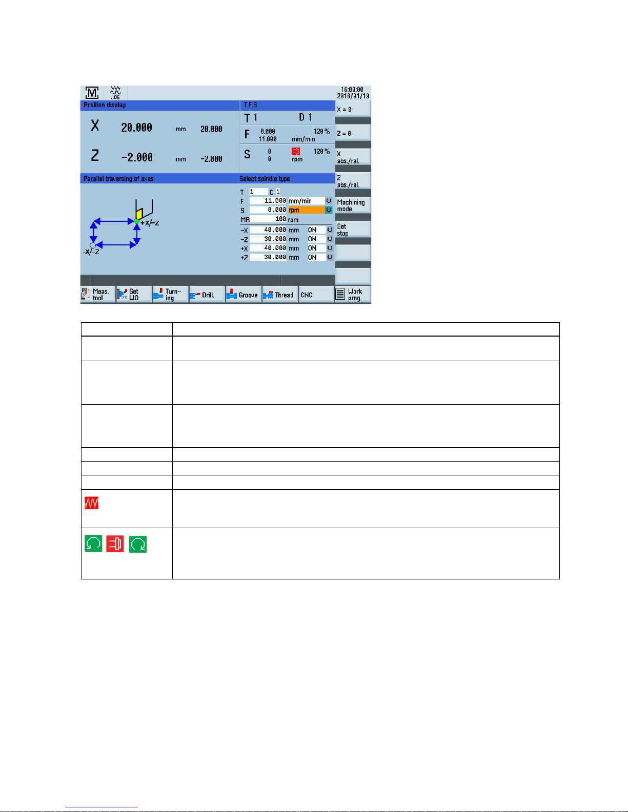
You have referenced the axes and accessed the MM+ operating area. The following screen represents the main screen of
this operating area.
Note about the position display in the main screen for MM+
● Absolute position display active:
The position value displayed in the large-size font is the absolute position. No additional value is shown.
● Relative position display active (see following diagram):
The position value displayed in the large-size font is the relative position. The position value displayed next to it in the
small-size font is the absolute position.
Controlling the axes and spindle
In manual machining mode, the axes and spindle can be controlled by the following methods:
● The compound slide rest is controlled by:
– Handwheels (Page 18) for the X and Z axes, or
– Axis direction switch (Page 18)
● The spindle is controlled by:
– Spindle direction of rotation switch (Page 19)
Page 15
Programming and Operating Manual (Manual Machine Plus (MM+), Turning)
01/2017
15
Values displayed in the position display and T, F, S
Displayed values
Meaning
In front of axis letters
+/-
• Current traversing direction of axes
S value/S type %
• Programmed value for the spindle speed (rev/min)
in either "rev/min" or "m/min", depending on the settings for the machining technology data.
•
Current position of the spindle override switch in %.
F value/F type %
• Programmed feed value
in either "m/min" or "mm/Rev", depending on the settings for the machining technology data.
•
Current position of the feedrate override switch in %.
T value
• Tool number of the tool used
D value
•
Tool offset applied
INC value
• Handwheel pulse weighting setting
•
Feed stop as a result of:
– Feedrate override at position 0%.
– An alarm is active which prevents the axes from moving.
•
Spindle status
– Spindle counter-clockwise
– Spindle stop
– Spindle clockwise
Page 16
Programming and Operating Manual (Manual Machine Plus (MM+), Turning)
16 01/2017
Machining and technology data
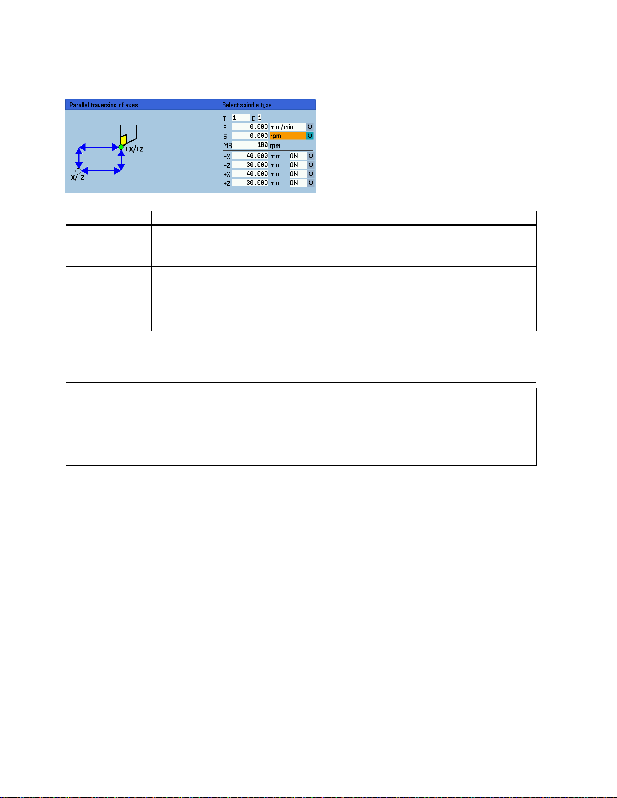
You must enter the machining technology data in the following input fields:
The machining technology data is as follows:
Parameter
Description
T
Tool number of the used tool (only for use of a manual tool-changer system)
F
Feedrate with choice of units mm/min (time feed) and mm/rev (revolutional feed),
S
Spindle type with the choice of units rpm (constant spindle speed) and m/min (constant cutting rate),
MR
Speed limitation for constant cutting rate
-X
-Z
+X
+Z
Positions of the limit stops, the limit stops can be activated using the toggle field "ON/OFF"
Note
Generally speaking, the relevant machining technology data must be entered before starting manual machining.
NOTICE
Device damage caused by excessive chucking device speed
When constant cutting rate (G96) is selected, the maximum permissible spindle speed, corresponding to the fitted tool
chucking device must be entered in the input field MR (spindle speed limitation).
Failure to pay sufficient attention to this point can lead to serious damage as a result of the chucking device speed being
exceeded.
4.2.1
Toggling the display
Functionality
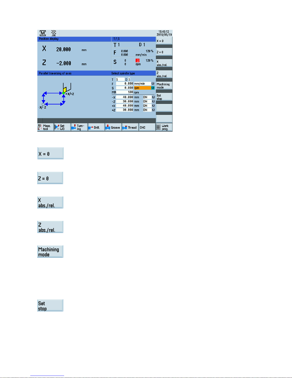
In the position display screen, you can edit the displayed values using the vertical softkeys.
Page 17
Programming and Operating Manual (Manual Machine Plus (MM+), Turning)
01/2017
17
Softkeys
Change the display to the relative position display mode and reset the display in the X axis.
Change the display to the relative position display mode and reset the display in the Z axis.
Toggle the display between the absolute position display mode and the relative position display mode in the X axis.
Toggle the display between the absolute position display mode and the relative position display mode in the Z axis.
Switching between the following operating modes:
● Traversing the axes parallel to the axis
● Taper turning
● Radius turning
The parameters for the machining type are displayed in the main screen of the MM+.
The current actual position of the relevant axis is transferred to the selected input field (-X/-Z/+X/+Z).
Page 18
Programming and Operating Manual (Manual Machine Plus (MM+), Turning)
18 01/2017
4.2.2
Machining with the handwheels
Functionality
The handwheels for the X and Z axes are not mechanically connected to the feed screws. Electronic pulse generators
mounted on the handwheels generate the information needed by the controller to execute the required traversing movement.
The handwheels are only active when the axis direction switch is in the zero position or the individual axis control keys are
disabled.
The distance traversed per handwheel pulse depends on the increment weighting setting.
Note
If the handwheel increment weighting is set t
o "0" or if the feedrate override weighting is in the "0" position, the handwheels
are disabled.
4.2.3
Setting the increment weighting for the handwheel
Functionality
Set the increment weighting from the Increment weighting machine control panel.
If you are unable to adjust the increment weighing, it will be because the controller's internal mode is incompatible with this
process.
Press the above hardkey once to resolve the problem.
NOTICE
Set increment weighing carefully
An incorrect increment weighting setting can result in damage to the workpiece, tool and machine.
4.2.4
Machining with axis direction switch
Functionality
You can move the axes in the desired direction by changing over the axis direction switch.
The feedrate at which an axis is traversed depends on the settings in the input fields for machining technology data.
The axis feedrate is also influenced by the feedrate override weighting setting and, depending on the option selected in the
input fields for machining technology data (revolutional feed/cutting speed), by the spindle override weighting.
If the above hardkey is also pressed, the axis is moved at the maximum possible speed, unless the feedrate override
weighting setting is used to specify a different value.
Page 19
Programming and Operating Manual (Manual Machine Plus (MM+), Turning)
01/2017
19
Note
If the feedrate override weighting is set to "0", any type of axis movement is b
locked.
With the revolutional feed and cutting speed settings, the feed is blocked until the spindle reaches the setpoint speed.
4.2.5
Spindle advance/reverse
Functionality
NOTICE
Start spindle
The spindle value should be checked before starting the spindle (for example, when changing the tool).
The last value set is active (this depends on the machinery construction of a machine manufacturer).
You start the spindle in the appropriate direction (spindle advance/reverse) by changing over the spindle direction switch:
Note
The spindle cannot be started, unless the chuck guard switch is enabled. Close the chuck guard.
NOTICE
Do not alter the chuck guard
Do not alter or adjust the chuck guard/chuck guard switch.
When the spindle is switched off, it brakes and comes to a halt. If a spindle brake is fitted, it is applied. If there is no spindle
brake or it is switched off, the spindle can be rotated freely once it has stopped.
The programmed spindle speed can be controlled by means of an appropriate spindle override switch setting (for example,
50 %).
4.2.6
Tool change
Functionality
A basic differentiation must be made between a manual and an automatic tool-changer system.
For an automatic system, the tool change is controlled by the PLC user program. The currently loaded tool is displayed in
the MM+ main screen.
For a manual system, the required tool number is manually entered from an input screen form.
Note
The following display machine data define the display:
•
MD290 CTM_POS_COORDINATE_SYSTEM
– = 0 -> Position of the tool after the turning center
– = 2 -> Position of the tool before the turning center (refer to the figure above)
•
MD1104 TOOL_CHG_MANUALMODE_MA
– = 0 -> Editing of the "T" and "D" fields is not possible, the fields are grayed out
– = 1 -> Editing of the "T" and "D" fields is possible
Page 20
Programming and Operating Manual (Manual Machine Plus (MM+), Turning)
20 01/2017
Operating sequences
Follow the sequence of operations below to enter the required tool number:
1.
Move the cursor onto the input field for the T value.
2. Enter the tool number using the nu
meric keys.
(The tool you wish to select must be set up in the tool list.)
3. Accept the tool number by pressing this hardkey.
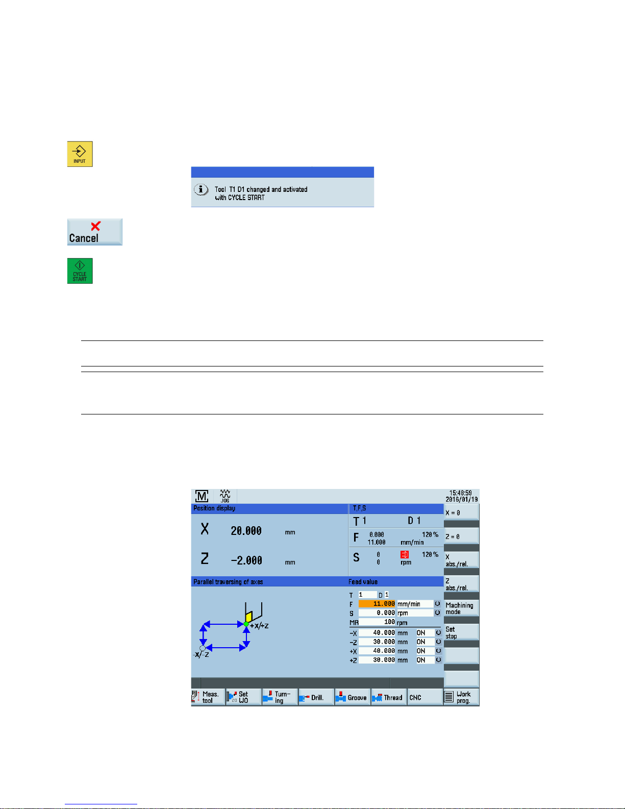
The following information text with the corresponding tool number is displayed:
Acknowledge this information text using this softkey.
4. Press this hardkey.
The tool number is changed.
Please note the following for a manual tool change:
● The real tool change on the machine (tool relocation) is finished.
● The appropriate tool number (tool offset) must be communicated to the control by making a manual entry.
Note
A new tool number may be selected only if all axes and the spi
ndle are stationary.
Note
The tool number entered in the T value field must correspond to the tool loaded into the machine; otherwise, the tool will
have to be recalibrated (see also section "
Measuring tools (Page 6)"). An uncalibrated or incorrectly calibrated tool can
lead to dimensional errors or to incorrect cutting values.
4.2.7
Changing the feedrate/spindle value
Changing the operating sequence, feed rate "F"/spindle value "S"
Follow the sequence of operations below to enter the required feedrate or spindle value:
1. Position the cursor on the input field for the value in the main screen for MM+.
Page 21
Programming and Operating Manual (Manual Machine Plus (MM+), Turning)
01/2017
21
2.
Edit the programmed value using the numeric keys.
3. Press this hardkey.
The value is activated.
Note
The F value (feed rate) or the S value (spindle) can only be changed if all axes and the spindle are stationary.
4.2.8
Changing the feedrate/spindle type
Changing the operating sequences feedrate type "F"
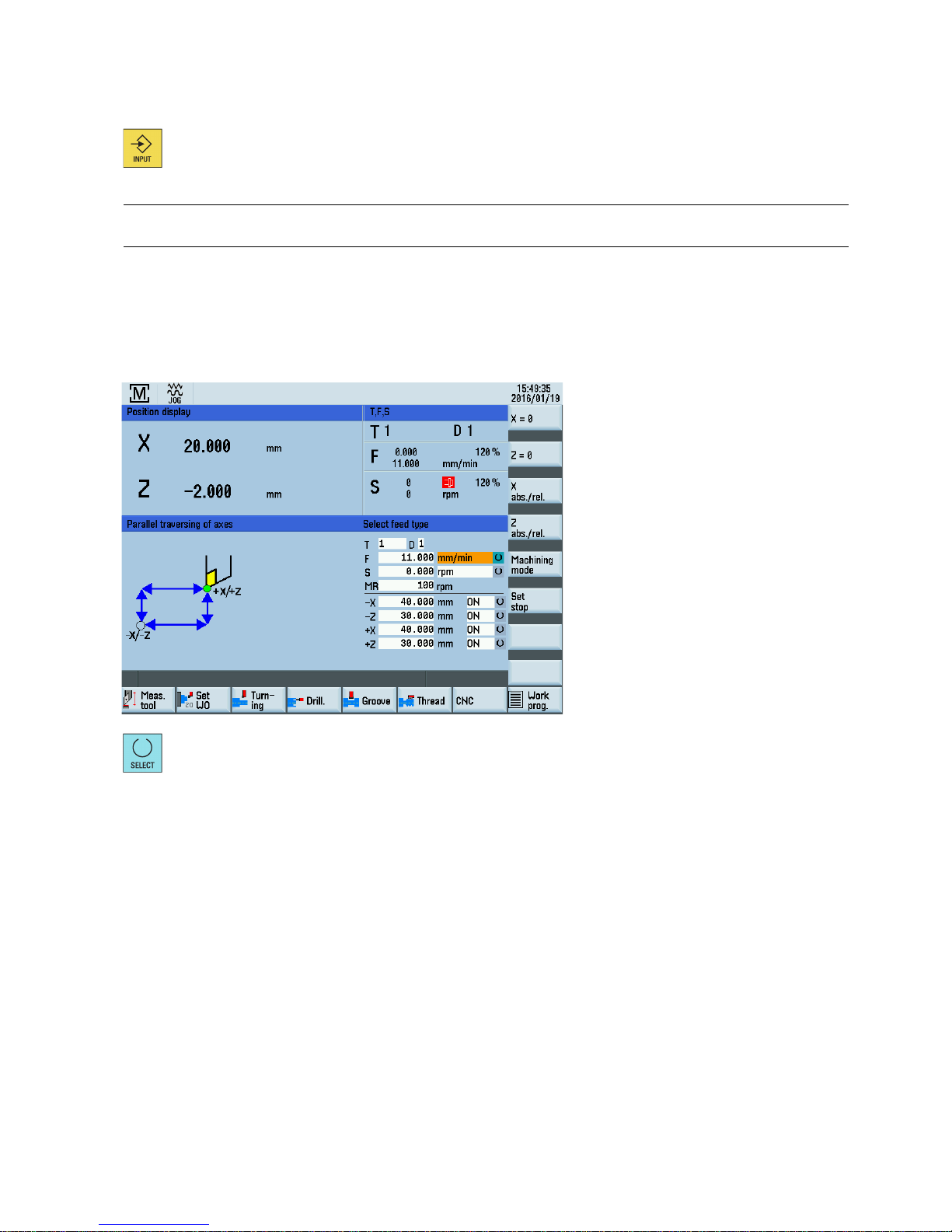
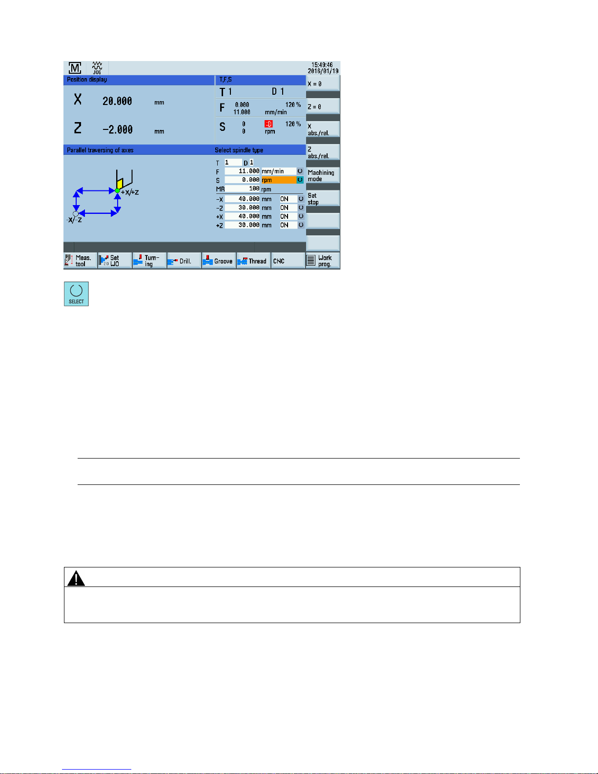
By pressing the cursor keys, you go to the display field which contains the currently programmed feedrate type (with an
orange background).
By pressing the above hardkey, you can choose one of the following feedrate types:
● Time feed (mm/min)
If time feed is selected, the axes are moved at the speed entered in this field (mm/min) (unless rapid traverse override is
activated). It can be influenced by the feedrate override switch setting.
The time feed is only possible for a constant spindle speed.
● Rotary feedrate (mm/rev)
In the "spindle speed + revolutional feedrate" or "constant cutting speed + revolutional feedrate" mode, the value entered
in this field determines the axis speed (unless rapid traverse override is activated). It is influenced directly by the feedrate
override weighting setting and indirectly by the spindle override weighting setting.
Changing the operating sequences spindle type "S"
By pressing the cursor keys, you go to the display field which contains the currently programmed spindle type (with an
orange background).
Page 22
Programming and Operating Manual (Manual Machine Plus (MM+), Turning)
22 01/2017
By pressing the above hardkey, you can choose one of the following spindle types:
● Constant spindle speed (rpm)
This value defines the programmed spindle speed for machining in the "spindle speed + time feed" or "spindle speed +
revolutional feedrate" mode.
The constant spindle speed is achieved only if no speed reduction is programmed by means of spindle override
weighting or with spindle setting data.
● Constant cutting rate (m/min)
Cutting speed input value for machining in the "cutting speed + revolutional feedrate" mode. The spindle speed is
adjusted to the machining diameter of the workpiece so that uniform cutting conditions are achieved.
Since the spindle would (in simple mathematical terms) have to rotate at an "infinitely high" speed at the rotational center
point in this mode, this speed is limited in the spindle setting data by the input value "MR".
The constant cutting speed can also be influenced by means of the feedrate and spindle override weighting settings.
Note
The feedrate or spindle type can only be changed if all axes and the spindle are stationary.
4.2.9
Change the speed limitation for constant cutting rate
Change the speed limitation operating sequences
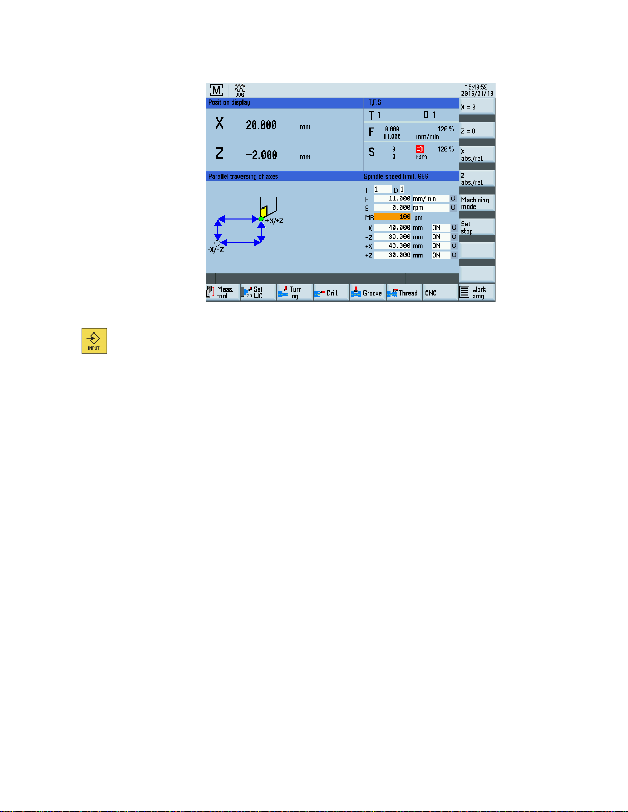
When a constant cutting rate (G96) is programmed, the maximum permissible spindle speed, corresponding to the fitted tool
chucking device, must be entered in the input field "MR" (spindle speed limitation).
WARNING
Spindle speed limitation
Failure to pay sufficient attention to this point can lead to serious damage as a result of the chucking device speed being
exceeded.
Page 23
Programming and Operating Manual (Manual Machine Plus (MM+), Turning)
01/2017
23
1. Position the cursor on the input field for the value in the MM+ main screen.
2.
Edit the programmed value using the numeric keys.
3. Press this hardkey.
The value is activated.
Note
The value m
ay be changed only when all axes and the spindle are stationary.
4.3
Manual machining with machining types
4.3.1
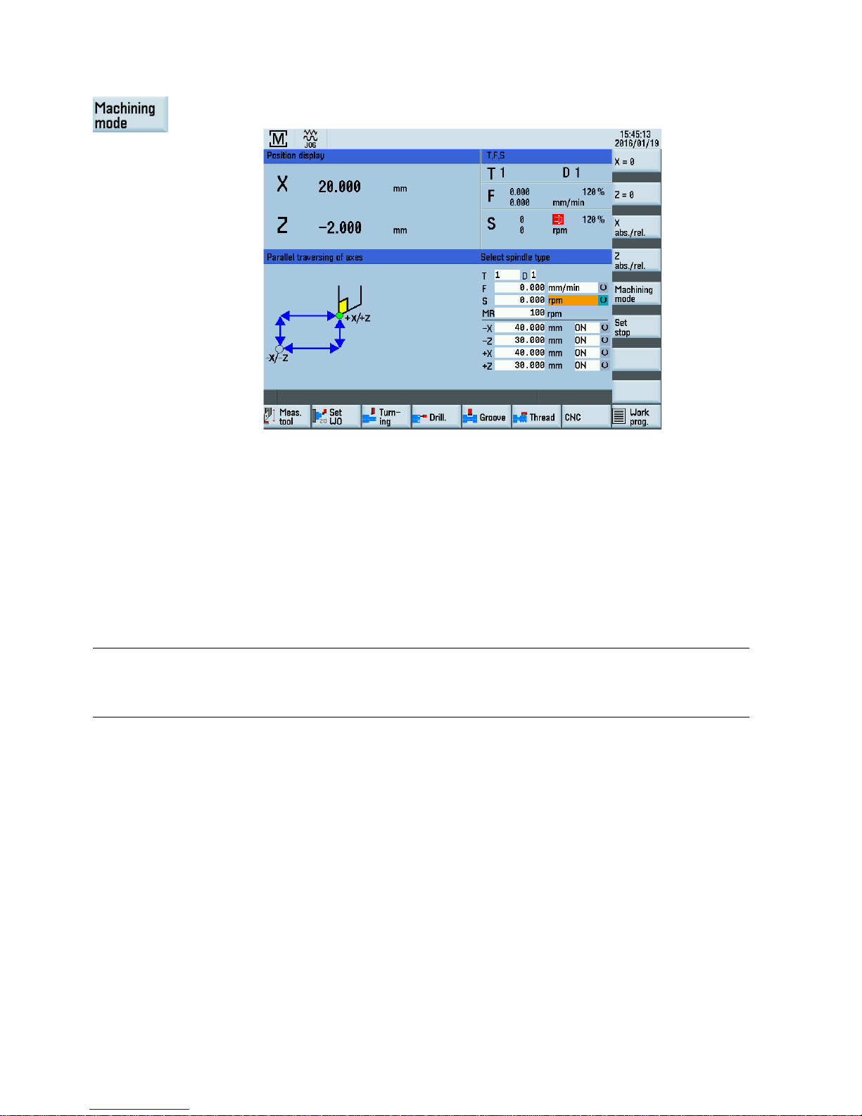
Axis-parallel traversal
Functionality
The axis-parallel traversal is used for the simple cutting on the workpiece or for positioning the axes.
If you move the axis direction switch, the control then moves the X and Z axes accordingly.
Operating sequences
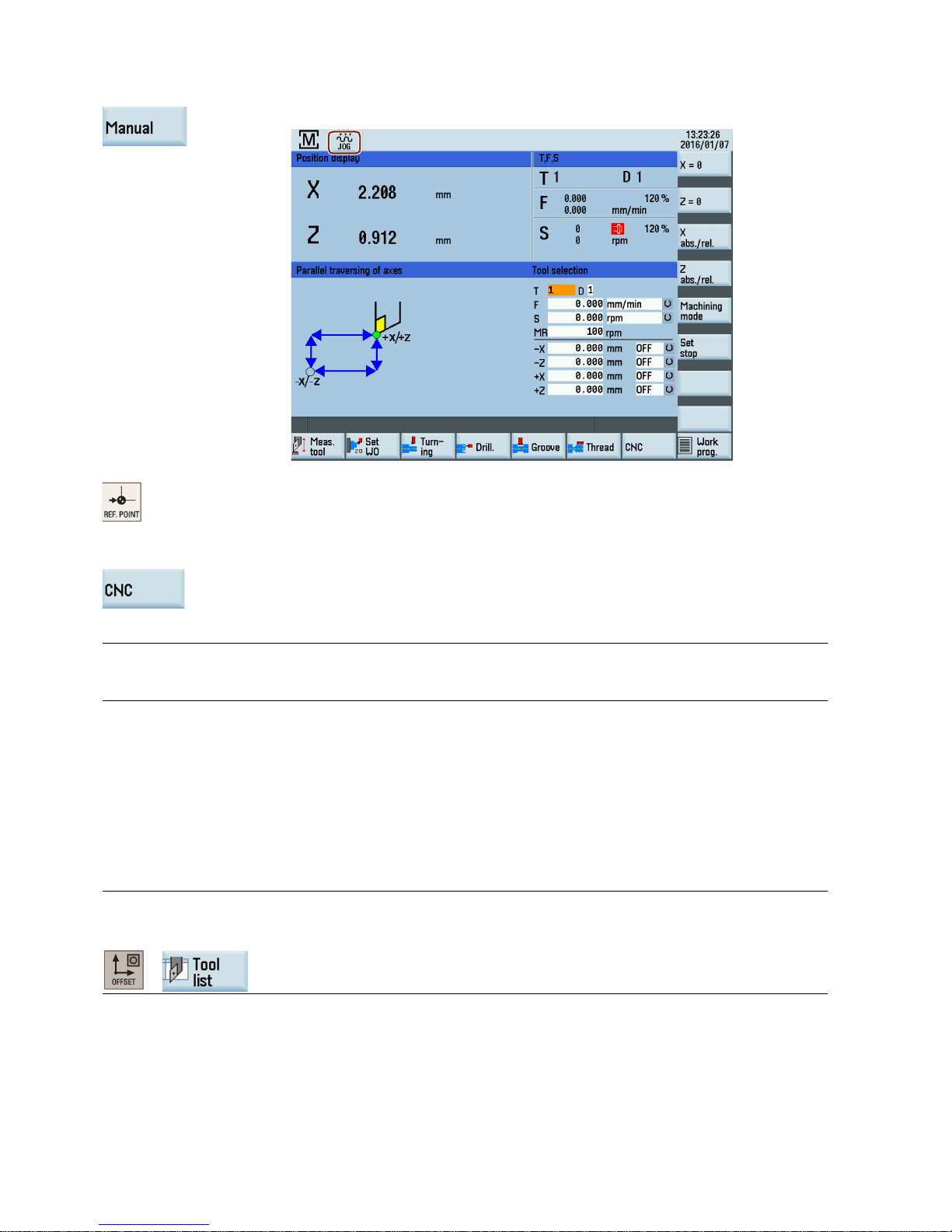
1. You can access the axis
-parallel traversal function via the main screen MM+.
Page 24
Programming and Operating Manual (Manual Machine Plus (MM+), Turning)
24 01/2017
2. If a different machining mode is active, press this soft
key until the following mode screen is
displayed.
4.3.2
Manual taper turning
Functionality
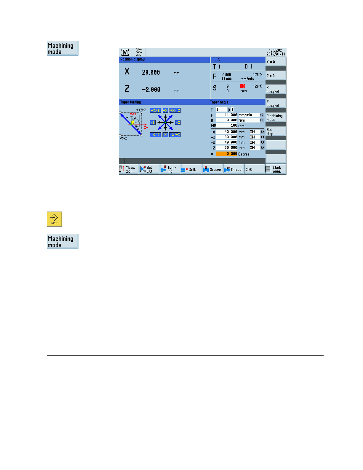
The manual taper turning function is intended for the simple production of tapered workpieces.
For this machining type, you need to enter an angle (taper angle α). The angle input rotates the controller's internal
coordinate system according to the angle value.
When you move the axis direction switch, the controller then uses the angle input to interpolate (and simultaneously
traverses) the X and Z axes accordingly.
The programmed axis feed then applies to the path being traversed and not to the corresponding axis.
If tapers with defined end points are to be turned, the use of limit stops is a helpful addition to this function.
Note
The desired taper is traversed only by
means of an axis direction switch or axis direction keys of the machine control panel
depending on the machine equipment.
A traversal using the handwheels is not possible.
Operating sequences
1.
You can access the manual taper turning function in the main screen for MM+.
Page 25
Programming and Operating Manual (Manual Machine Plus (MM+), Turning)
01/2017
25
2. Press t
his softkey until the following screen is displayed.
3. The input field for the taper angle "
α" is immediately displayed with an orange background
when the machining mode is selected. You must enter the angle using the numeric keys.
A positive angle value rotates the coordinate system in traverse direction X+.
A negative angle value rotates the coordinate system in traverse direction X-.
4. The entered value is immediately accepted using this hardkey.
The taper angle remains active until you exit this machining mode by pressing this sof
tkey.
4.3.3
Manual radius turning
Functionality
The manual radius turning function is designed to simplify the machining of inside and outside radii.
The positions of the axes at the time that machining is selected form the starting point for the radii to be traversed.
When you move the axis direction switch, the control then uses the input values to interpolate (and simultaneously traverse)
the X and Z axes accordingly.
The programmed axis feed then applies to the path being traversed and not to the corresponding axis.
Note
The desired radius is traversed only by means of an axis direction switch or axis direction keys of the machine control panel
depending on the machine equipment.
A traversal using the handwheels is not possible.
Operating sequences
1.
You can access the manual radius turning function in the main screen for MM+.
Page 26
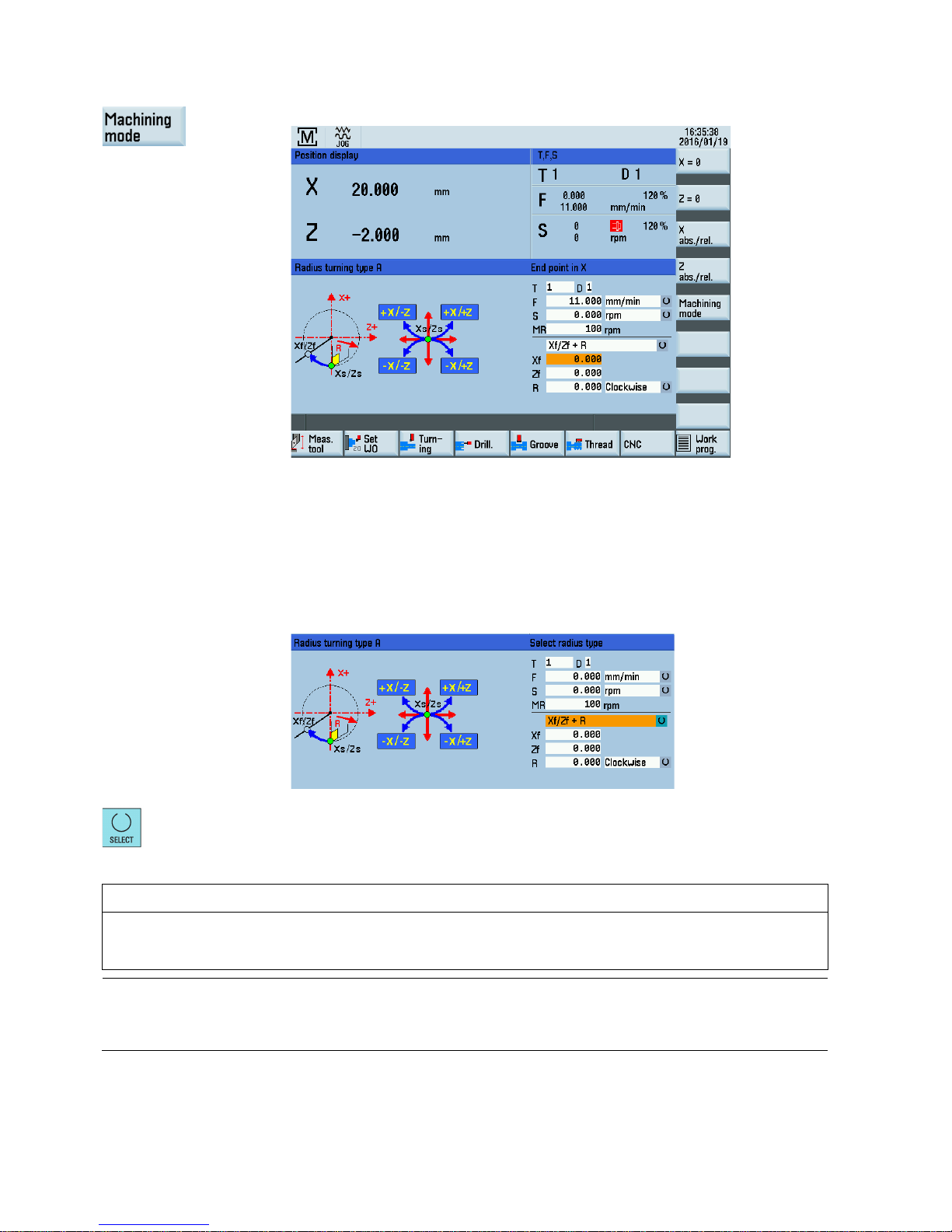
Programming and Operating Manual (Manual Machine Plus (MM+), Turning)
26 01/2017
2. Press this softkey until the following
machining mode screen is displayed.
You can exit the machining mode by pressing this softkey again.
The three types available for radius turning differ in the specification of the values for spec
i-
fying the radius.
•
Type A
•
Type B
•
Type C
3. By pressing the cursor keys you can go to the
display field which contains the active radius
type (with an orange background).
4. By pressing this hardkey, you can select the radius type.
NOTICE
Input values correctly
Omitting or using the wrong sign for the input values or entering the wrong arc direction can lead to a collision and may
destroy the tool or the workpiece.
Note
Any limit stops that are activated should be disabled before starting radius turning or set to a value outside the traversing
range needed for radius turning; otherwise, an error message is transmitted by the controller which preven
ts the "Manual
radius turning" function being started.
Page 27
Programming and Operating Manual (Manual Machine Plus (MM+), Turning)
01/2017
27
4.3.3.1
Radius turning type A
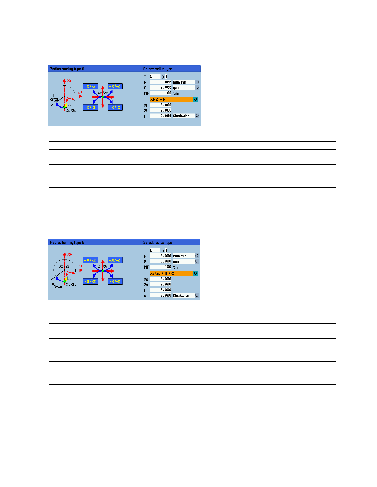
For radius turning type A, the radius to be machined is specified by the end point, the radius and the machining direction.
Parameter
Parameter
Description
Xf This input value describes the position of the circle end point in the X axis. The input
value is evaluated as absolute position (in the diameter).
Zf This input value describes the position of the circle end point in the Z axis. The input
value is evaluated as absolute position.
R
This input value describes the radius to be traversed.
Counterclockwise/Clockwise This toggle field selects whether a circle must be traversed in the clockwise or coun-
terclockwise direction.
4.3.3.2
Radius turning type B
For the radius turning type B, the radius to be machined is specified by the center, the radius, the opening angle and the
machining direction.
Parameter
Parameter
Description
Xc This input value describes the position of the circle center in the X axis. The input
value is evaluated as absolute position (in the diameter).
Zc This input value describes the position of the circle center in the Z axis. The input
value is evaluated as absolute position.
R
This input value describes the radius to be traversed.
α
This input value describes the opening angle of the radius to be traversed.
Counterclockwise/Clockwise This toggle field selects whether a circle must be traversed in the clockwise or coun-
terclockwise direction.
Page 28
Programming and Operating Manual (Manual Machine Plus (MM+), Turning)
28 01/2017
4.3.3.3
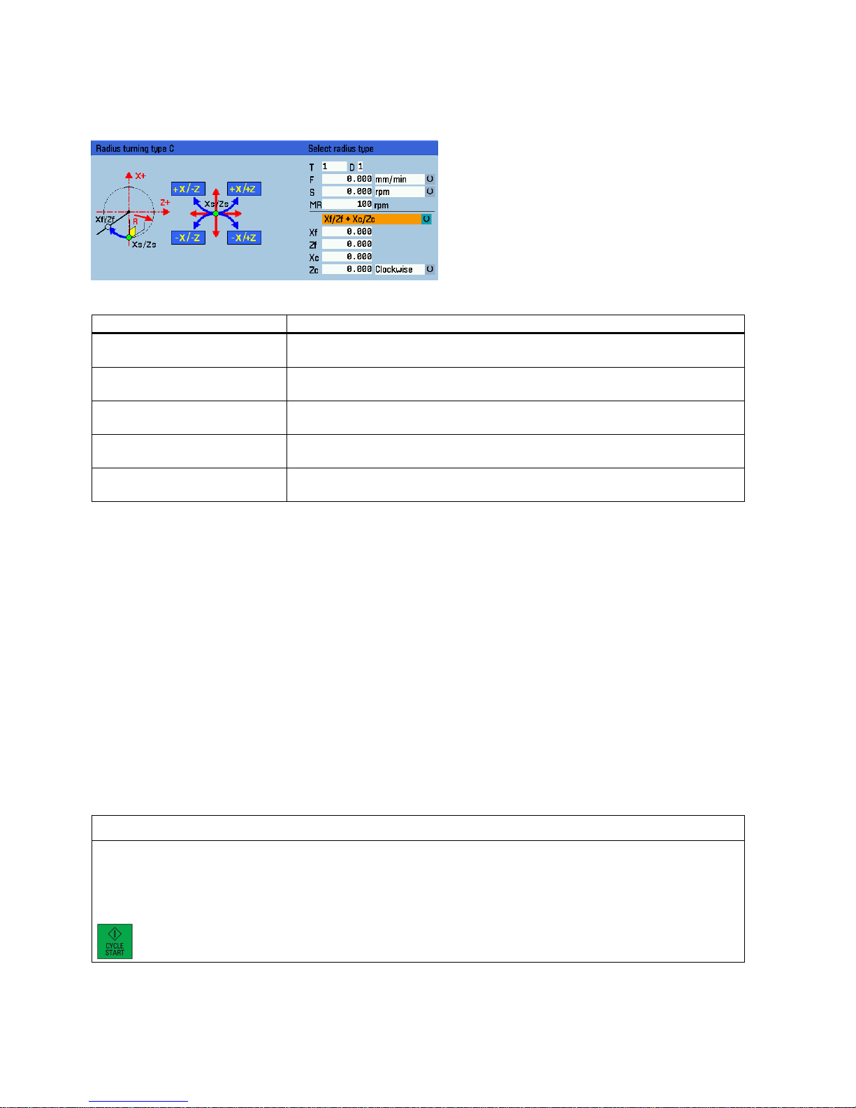
Radius turning type C
For the radius turning type C, the radius to be machined is specified by the center, the end point and the machining direction.
Parameter
Parameter
Description
Xf This input value describes the position of the circle end point in the X axis. The input
value is evaluated as absolute position (in the diameter).
Zf This input value describes the position of the circle end point in the Z axis. The input
value is evaluated as absolute position.
Xc This input value describes the position of the circle center in the X axis. The input
value is evaluated as absolute position (in the diameter).
Zc This input value describes the position of the circle center in the Z axis. The input
value is evaluated as absolute position.
Counterclockwise/Clockwise This toggle field selects whether a circle must be traversed in the clockwise or coun-
terclockwise direction.
4.4
Manual machining using cycles (functions)
4.4.1
Principle operating sequence
Functionality
You can perform the following functions manually:
● Drilling centric
● Tapping
● Groove cycles/Expan. groove
● Thread cutting
● Rough turning of contours
When manually machining these functions, the operating sequence is essentially executed in the same way.
Requirement
The following requirements must be fulfilled before you can execute the functions:
NOTICE
Damage to the tool, workpiece or machine
In machining operations, a spindle rotating in the wrong direction can cause serious damage to the tool, workpiece or
machine.
Check the direction of rotation of the spindle before pressing the following key.
Page 29
Programming and Operating Manual (Manual Machine Plus (MM+), Turning)
01/2017
29
● The spindle is rotating in the correct direction.
● Any axis position from which the workpiece position is machined can be approached without risk of collision.
● All parameters for the cycles are correctly assigned.
Note
Parts can be machined manually only by a spindle started in the correct rotational direction. An
error message is otherwise
displayed.
Operating sequences
1. Press this softkey in the main screen of MM+.
2. Press this softkey and then parameterize the function.
Page 30
Programming and Operating Manual (Manual Machine Plus (MM+), Turning)
30 01/2017
3. This softkey will support you with the parameterization and execution of functions.
The actual position value of the relevant axis is transferred to the parameter input fields
when you press this softkey.
The input field must be selected with
the cursor keys; otherwise, an error message is dis-
played when you accept the axis position, saying that the value cannot be accepted.
This softkey takes you back to the main screen.
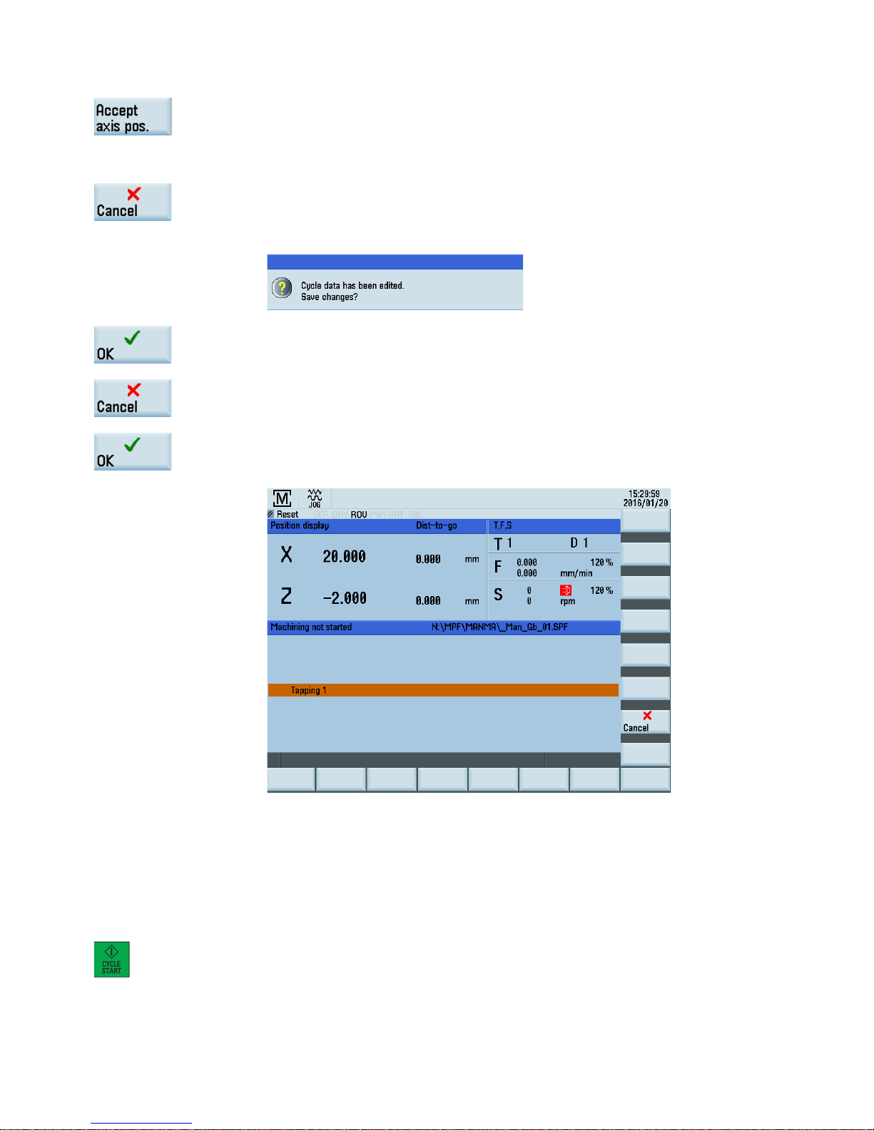
If you have edited any values, the following prompt window appears:
4.
Your inputs are accepted when you press this softkey.
Your inputs are discarded when you press this softkey.
5. The function was parameterized (for
example, thread tapping).
Activate the function using this softkey.
The following execute screen appears:
The current machining status is displayed in the center of the execute screen. This status
could be one of the following:
•
Machining not started
•
Machining active
•
Machining aborted
•
Machining interrupted
•
Machining finished
6. Start machining using this hardkey.
The machining operation on the workpiece is executed.
Page 31

Programming and Operating Manual (Manual Machine Plus (MM+), Turning)
01/2017
31
Press this hardkey if you want to interrupt the machining operation. The selected direction of
the spindle rotation continues to be activated.
By pressing this hardkey, "JOG" operatin
g mode is automatically changed, that is, you can
traverse the axes manually. By continuing executing a cycle start , the interruption point is
approached again and execution of the program is continued.
7. If machining was terminated (for example, completed), the execution screen can b
e exited
using this softkey.
Note
In step 2, a detailed parameter description of each function can be found in the relevant sections.
4.4.2
General parameters
General parameters
When parameterizing the particular functions, among others, the following general parameters are available:
Parameter
Description
Function name
Number of the selected function
Tool (T)
Tool number
Compensation (D)
Tool offset number
Direction of spindle
rotation
Toggle field for spindle direction of rotation (clockwise/counterclockwise)
Feed value (F)
Feed value
Type of feedrate
Toggle field for feed type (mm/min or mm/rev)
Spindle speed (S)
Spindle speed value
Spindle type
Toggle field for spindle type (rev/min)
Coolant
Toogle field for coolant function (coolant OFF/coolant ON)
Machining The type of machining operation can be selected in this toggle field. The following options are
available: complete machining, roughing only, and finishing only.
Position The machining direction can be selected with the first toggle field.
The following options are available: outside right, inside right, and outside left. The diagram displayed on the screen changes to indicate which option is selected.
The cutting direction can be selected with the second toggle field.
Available selection
: infeed in the longitudinal axis and roughing cut in the transverse axis (face), or
roughing cut in the longitudinal axis and infeed in the transverse axis (long.). The current selection
is shown in the form of a diagram on the screen.
Reference
Contour start position in the longitudinal axis (absolute position of the Z axis).
Note
Additional parameter descriptions for the individual functions are provided in the corresponding chapters.
Page 32
Programming and Operating Manual (Manual Machine Plus (MM+), Turning)
32 01/2017
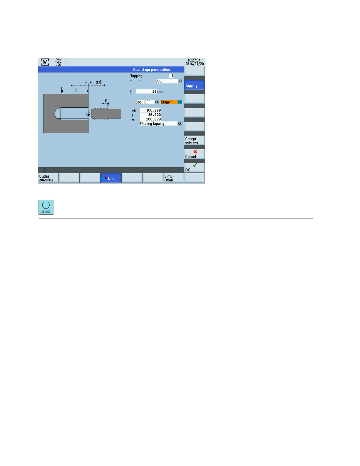
Optional parameter, gear stage pre-selection
In the input fields for the relevant manual machining, for example, thread tapping, it is possible to pre-select the gear stage.
If a gear unit is installed on the machine, you can select the gear stage by using the following hardkey:
Note
The selection of the gear stages can be changed by
the following general machine data:
•
$MN14512 USER_DATA_HEX[31]
– 1's digit -> Number of selectable gear stages
– 10's digit -> = 1 -> With selection of the automatic gear stage
4.4.3
Manual drilling centered
Functionality
The "Manual drilling centered" function is designed to produce deep-hole drill holes in the turning center. Before you start the
cycle, you must position the tool in such a way that it can approach the programmed Z initial position without risk of collision.
The function itself will position the tool on the center of rotation.
Page 33
Programming and Operating Manual (Manual Machine Plus (MM+), Turning)
01/2017
33
Operating sequences
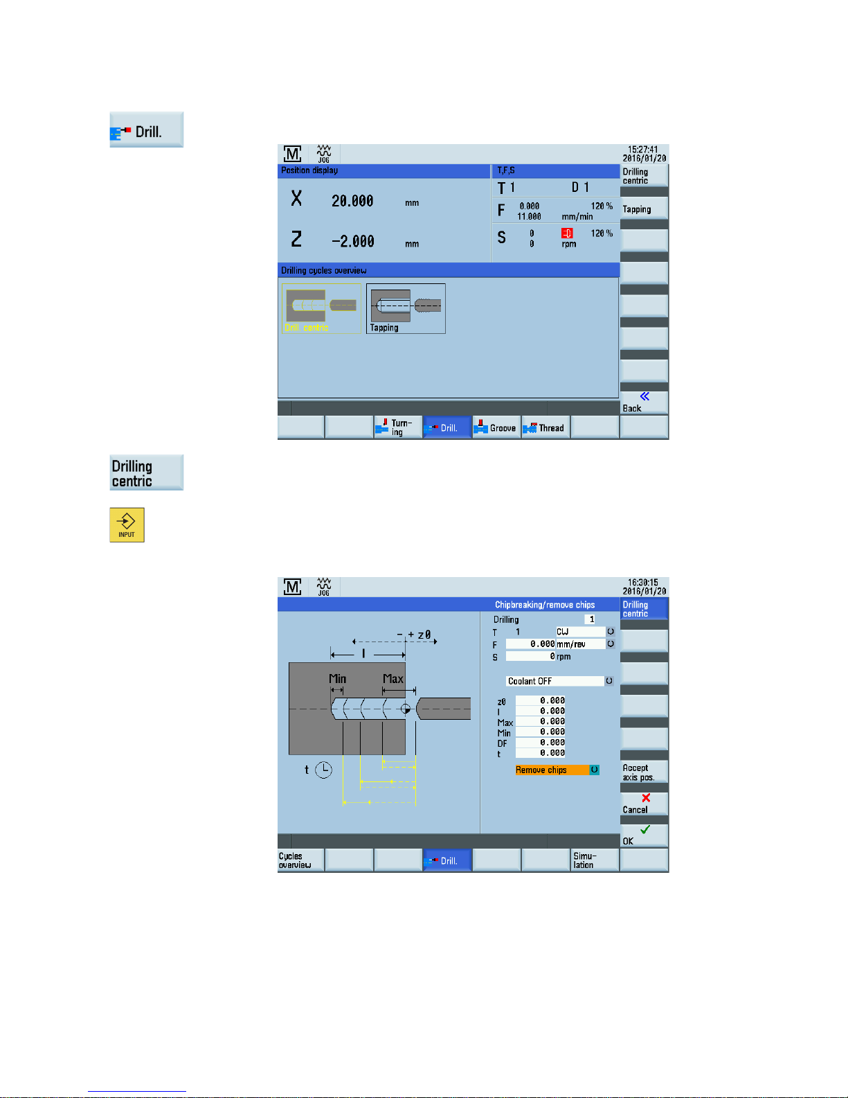
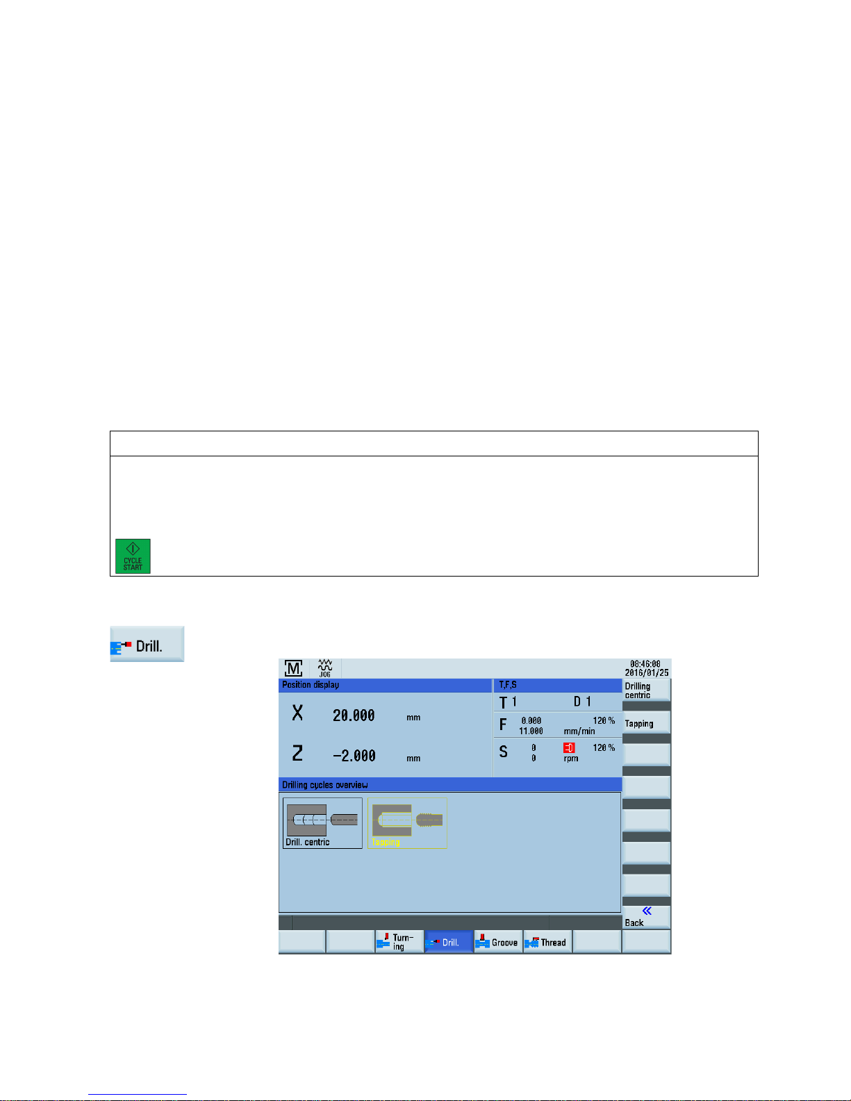
1. You can access the drilling cycle overview by pressing this softkey in the basic screen for
MM+.
2. You can access the "Manual center drilling" function by pressing this softkey in the drilling
cycle overview.
Alternatively, you can select this function with cursor keys and activate it wit
h this hardkey.
Remove chips:
Page 34
Programming and Operating Manual (Manual Machine Plus (MM+), Turning)
34 01/2017
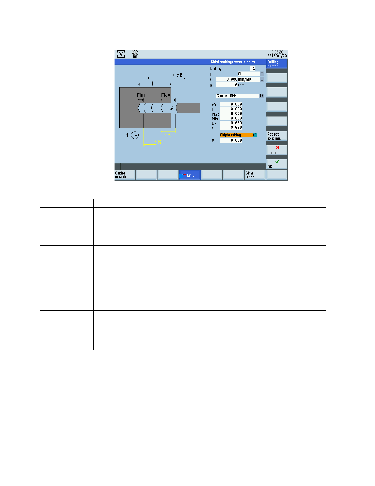
Chip breaking:
Parameter
Parameter
Description
Reference (z0) Start position for the drill hole in the longitudinal axis
(absolute position of Z axis)
Drilling depth (l) Enter the depth of the drill hole to be created, taking the start position for the drill hole ("Refer. z0")
as the starting point. The drilling direction is always towards the chuck and cannot be reversed.
Max. infeed (Max) Maximum infeed value for the first infeed in the longitudinal axis
Min. infeed (Min)
Minimum infeed value in the longitudinal axis, which must be observed for the final infeed.
Degression factor f
Degression factor: the value by which the second and all subsequent infeeds in the longitudinal axis
are multiplied. The following general rule applies: An input value greater than 1 increases the infeed
depth with each infeed, an input value of less than 1 reduces it with each infeed. To switch off de-
gression, enter 1 (or 0) here.
Dwell time (t)
Dwell time on reaching the drilling depth
Return travel distance (chip breaking
only) (R)
Return travel distance in the longitudinal axis for chip breaking.
Chip breaking/remove chips
With this toggle field you can select between machining with "chip breaking" or "remove chips".
With "chip breaking", on reaching the corresponding infeed depth the tool is retracted in the longitudinal axis by a defined value (chip breaking) before the next infeed. With "remove chips" on the
other hand, the tool is withdrawn from the drill hole on reaching the corresponding infeed depth.
The next infeed then continues as usual. The current selection is shown as a graphic in the left-
hand section of the screen.
Drilling
The machining sequence is as follows:
1. Starting from the current axis position, the tool is traversed to the cycle start point in the longitudinal axis. This is
calculated internally from the value for the "Reference z0" parameter (taking into account the clearance distance).
2. The transverse axis is positioned to the center of rotation.
3. The first infeed in the axial axis (as defined in the "Infeed Max." parameter) is then performed.
4. The subsequent traversing movement in the axial axis depends on whether "chip breaking" or "remove chips" has been
selected. With "chip breaking", the tool is retracted in the longitudinal axis by the value set in the "return travel"
parameter; with "remove chips", the longitudinal axis is positioned at the cycle start point.
Page 35
Programming and Operating Manual (Manual Machine Plus (MM+), Turning)
01/2017
35
5. The subsequent infeeds in the longitudinal axis are always calculated in the same way: new infeed value = last infeed
value x factor + return travel value The new infeed value is monitored to ensure that it complies with the value for the
"Infeed Min." parameter. If the infeed value is below the minimum infeed, this value is imposed, provided that the drilling
depth allows it. The calculation is followed by the infeed in the longitudinal axis.
6. Infeed motion and "chip breaking/remove chips" then alternate until the drilling depth specified in the "Length I"
parameter is reached.
7. Once the required drilling depth is reached, the waiting time specified in the "Dwell t" parameter begins.
8. At the end of this waiting time, the tool is traversed to the cycle start point in the longitudinal axis.
4.4.4
Manual thread tapping
Functionality
The manual thread tapping function is designed to produce internal threads in the turning center, either with a compensating
chuck or in a rigid tapping operation.
Before you start the cycle, you must position the tool in such a way that it can approach the programmed Z initial position
without risk of collision. The function itself will position the tool on the center of rotation.
The machining feedrate is calculated from the programmed spindle speed and the thread pitch. This feedrate might not be
the same as the programmed feedrate.
If you have selected the cutting rate as the spindle type, the value set for the maximum spindle speed with G96 or the value
for the maximum spindle speed is applied for thread tapping. (because the thread is tapped in the turning center, that is, X=0)
NOTICE
Setting the spindle override weighting to 100%
If the time feed is selected in the input fields of machining technology data, for the sake of the pitch to be calculated
correctly, the spindle override weighting must be set to "100%"; otherwise, the tapping tool or workpiece may be damaged.
Prior to pressing the following hardkey, check that the spindle override weighting is set to 100%.
Operating sequences
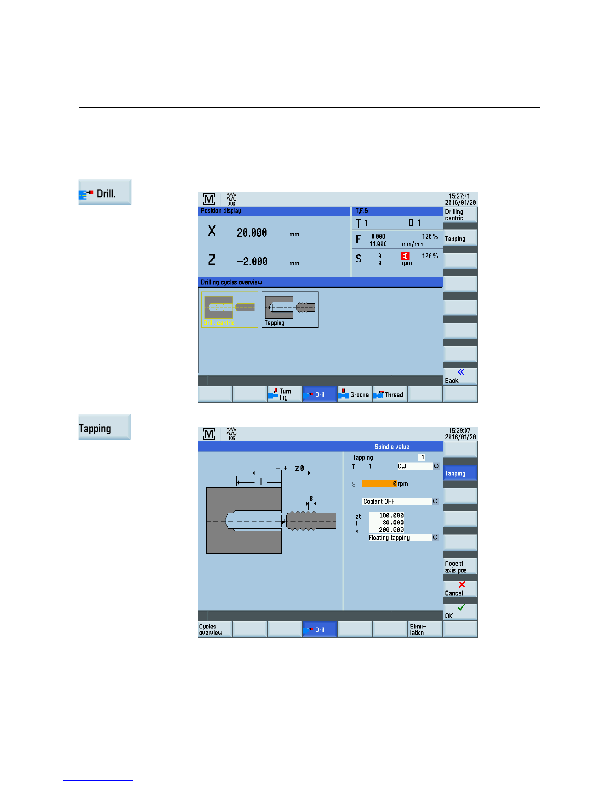
1. You can access the drilling cycle overview by pressing this softkey in the basic screen for
MM+.
Page 36
Programming and Operating Manual (Manual Machine Plus (MM+), Turning)
36 01/2017
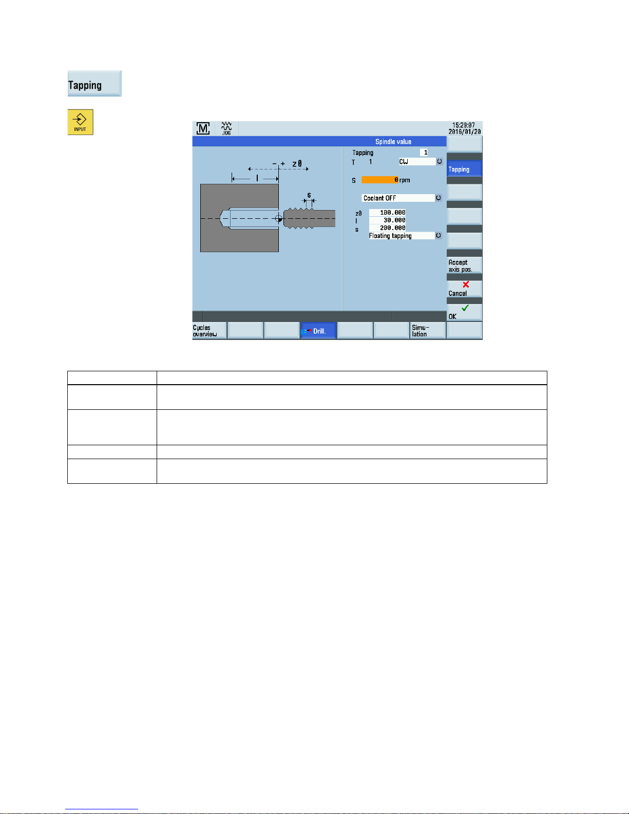
2. You can access the manual tapping function by pressing this softkey in the drilling cycle
overview.
Alternatively, you can select this function with cursor keys and activate it with this
hardkey.
Parameters
Parameter
Description
Reference (z0) Start position for the drill hole in the longitudinal axis
(absolute position of Z axis)
Drilling depth (l) Enter the thread length here. The tapping direction is always towards the chuck and cannot be
reversed. The choice of a left-hand or right-hand thread depends on the direction of rotation of the
spindle and the thread tapping tool.
Lead (s)
Enter the thread pitch here.
With compensating
chuck/Rigid tapping
Depending on the manufacturer, you can select as to whether the machining is carried-out with or
without compensating chuck.
Tapping operation
The machining sequence is as follows:
1. Starting from the current axis position, the tool is traversed to the cycle start point in the longitudinal axis. This is
calculated internally from the value for the "Reference z0" parameter (taking into account the clearance distance).
2. The transverse axis is positioned to the center of rotation.
3. The controller then waits (at the cycle start point) for the next zero mark of the spindle encoder in order to start the axis
movement in the longitudinal axis (defined thread start point).
4. When the thread length (end point) is reached, the spindle and longitudinal axis change direction and withdraw the
tapping tool from the drill hole again.
5. The longitudinal axis then stops at the cycle start point and the spindle changes direction again. The spindle is now
running in the direction in which it was originally started.
Page 37
Programming and Operating Manual (Manual Machine Plus (MM+), Turning)
01/2017
37
4.4.5
Manual grooving/parting
Functionality
The manual grooving function is suitable for producing grooves on the peripheral surface and face end and for tapping
turned parts. Groove cycles can be used to produce filleted corners or beveled edges on surfaces.
In addition, the multiple execution function can be used to produce multiple tappings and multiple grooves with a uniform
offset.
Note
The grooving tool must be configured in the tool list; in doing so, the width of the tool must be programmed via the panel
width or via cutting edge 1 (D1) or cutting edge 2 (D2
).
4.4.5.1
Groove cycle - single
Operating sequences
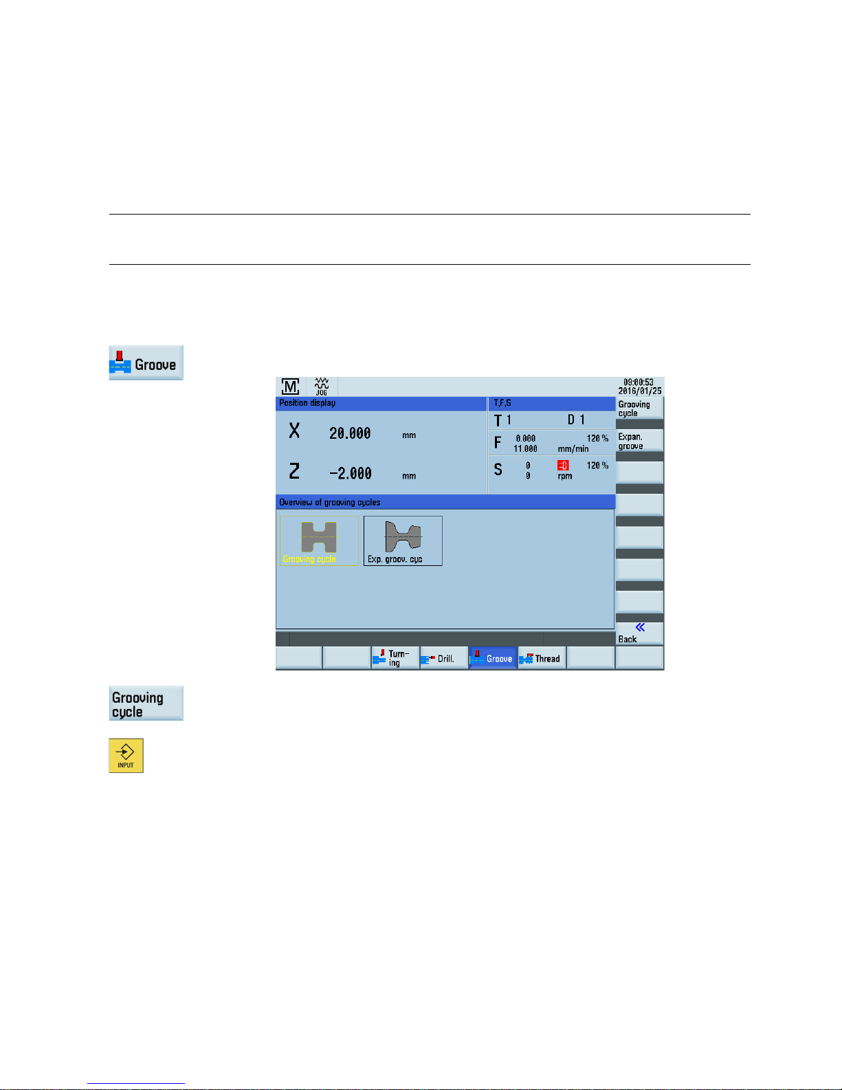
1. You can access the grooving cycle overview by pressing this softkey in the basic screen for
MM+.
2. You can access the manual grooving function by pressing this softkey in the grooving cycle
overview.
Alternatively, you can select this function with cursor keys and activate it with this hardkey.
Page 38
Programming and Operating Manual (Manual Machine Plus (MM+), Turning)
38 01/2017
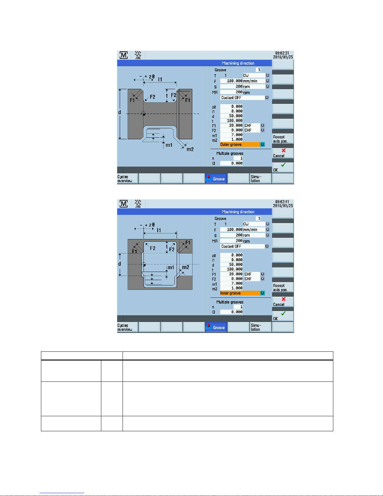
Outer groove:
Inner groove:
Parameter
Parameter
Description
Reference z0 Starting position for the groove. The edge of the groove facing the chuck is always
specified here. The value to be entered indicates the absolute position in the longitudi-
nal axis (Z axis).
Groove width l1 This value is the groove width, which together with the value for "Reference z0" speci-
fies the absolute position of the edge of the groove on the side of the groove facing
away from the spindle. If the groove width setting is the same as the tool width, and "0"
is assigned to the parameters "Edge F1" and "Edge F2" (selection between "CHF" and
"RND"), the tapping function is activated.
Diameter d Starting diameter for the groove. The value to be entered is the absolute position in the
transverse axis (X axis).
Page 39

Programming and Operating Manual (Manual Machine Plus (MM+), Turning)
01/2017
39
Parameter
Description
Groove depth t This value is the groove depth which together with the value for "Diameter d" specifies
the absolute position of the base of the groove.
Chamfer/radius F1 Depending on the option selected, this value forms either an input radius (display
"RND") or an input chamfer (display "CHF") of less than 45
0
on both sides of the
groove. You can toggle between RND and CHF using the toggle key. An input value of
0.0 switches this function off.
Chamfer/radius F2 Depending on the option selected, this value forms either a radius (display "RND") or a
chamfer (display "CHF") of less than 45
0
on both sides of the groove as the transition to
the base of the groove. You can toggle between RND and CHF using the toggle key. An
input value of 0.0 switches this function off.
Max. infeed depth m1 Enter the maximum infeed depth for roughing during grooving. The cycle's internal in-
feed calculation ensures that this input value is not exceeded during machining.
Finishing allowance
m2
Finishing allowance perpendicular to the contour.
Outer groove/inner
groove
In this toggle field you can select whether an internal or an external groove is required.
The selection is indicated by a diagram on the screen.
Groove cycle - single
The machining sequence is as follows:
1. Starting from the current axis position, the first calculated groove position is approached (diagonally) in both axes, taking
into account the clearance distance and finishing allowance.
2. Execute the depth infeeds as a roughing motion in the transverse axis (X axis): each infeed depth is calculated internally
so that firstly the setting "m1" is not exceeded and secondly the infeed distance is kept uniform until the base of the
groove is reached (taking into account the final machining allowance). After each infeed, the tool is retracted by the
clearance distance for chip breaking.
3. When the base of the groove is reached for the first time, the tool is withdrawn from the material at the programmed
feedrate.
4. This is followed by the width infeed in the longitudinal axis: the width offset is calculated internally, taking into account the
tool width (length "l2") and the groove width (length "l1") so that the machining is as uniform as possible.
5. Depth infeeds are then alternated as roughing motion and width offset until the entire groove contour has been cleared.
The only difference between the first depth infeed and the others is that when the base of the groove is reached, the tool
is retracted by the clearance distance and then moved out of the groove in rapid traverse.
6. Finishing is started immediately after the roughing operation. The entire contour is traversed from both sides to the
center of the base of the groove at the feedrate specified in the input fields of machining technology data before the start
of the cycle.
7. Finally, the original position of the axes before the start of machining is approached diagonally.
4.4.5.2
Groove cycle - multiple
Functionality
Note
The multiple groove function supplements the single groove option. This function can be used only if all the parameters for
the single groove function have been assigne
d.
Page 40
Programming and Operating Manual (Manual Machine Plus (MM+), Turning)
40 01/2017
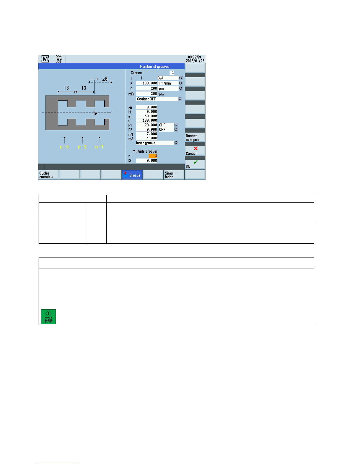
As soon as you position the cursor in any of the input fields in the multiple grooves area of the screen, the display changes
from single groove to multiple grooves:
Parameter
Parameter
Description
Distance l3 Groove offset in the longitudinal axis (Z axis): This input value determines the offset be-
tween several identical grooves during production. The direction of the groove offset be-
tween the individual grooves is always towards the chuck.
Number n Number of grooves to be produced. Entering "0" or "1" here has the same effect: A single
groove is produced. When you enter a value of ">1", the appropriate number of grooves is
machined. The input value in parameter "Length I3" defines the necessary offset.
NOTICE
Reserve sufficient clearance from the spindle
When you are machining multiple grooves, make sure that there is sufficient clearance from the spindle as measured from
starting position "Reference z0" to allow all parameterized grooves to be machined. There is otherwise a risk of collision
between the tool and the chuck.
Check the plausibility of the input values before pressing the following key.
Multiple grooves
The machining sequence is as follows:
1. Starting from the current axis position, the first groove is produced as described for the single groove function.
2. The starting point for the next groove is then approached in the longitudinal axis (X axis), taking into account the
clearance distance. The offset is always in the direction of the spindle (chuck).
3. Another complete groove is then machined (as described for the single groove function).
4. Groove machining and offset in the axial axis then alternate until the number of grooves specified in the "Number n"
parameter has been produced.
5. On completion of the final groove, the original position of the axes before the start of machining is approached diagonally.
Page 41
Programming and Operating Manual (Manual Machine Plus (MM+), Turning)
01/2017
41
4.4.5.3
Extended grooving
Operating sequences
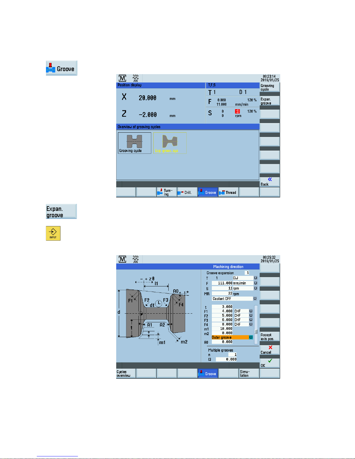
1. You can access the grooving cycle overview by pressing this softkey in the basic screen for
MM+.
2. You can access the extended grooving function by pressing this softkey in the grooving
cycle overview.
Alternatively, you can select this function with cursor keys and activate it with thi
s hardkey.
Outer groove:
Page 42
Programming and Operating Manual (Manual Machine Plus (MM+), Turning)
42 01/2017
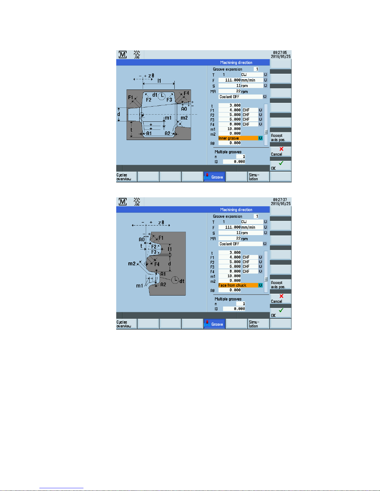
I
nner groove:
Face from chuck:
Page 43
Programming and Operating Manual (Manual Machine Plus (MM+), Turning)
01/2017
43
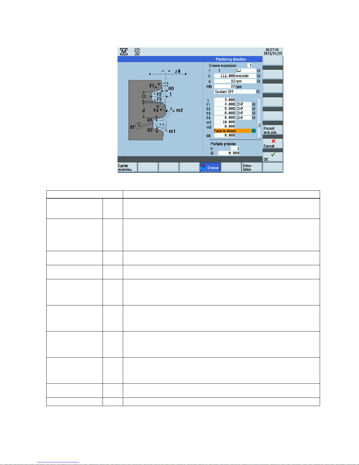
Face to chuck:
Parameter
Parameter
Description
Reference z0 Starting position for the groove. The edge of the groove facing the chuck is always
specified here. The value to be entered indicates the absolute position in the longitudi-
nal axis (Z axis).
Groove width l1 This value is the groove width, which together with the value for "Reference z0" speci-
fies the absolute position of the edge of the groove on the side of the groove facing
away from the spindle. If the groove width setting is the same as the tool width, and "0"
is assigned to the parameters "Edge F1" and "Edge F2" (selection between "Chamfer
CHF" and "Radius RND), the tapping function is activated.
Diameter d Starting diameter for the groove. The value to be entered is the absolute position in the
transverse axis (X axis).
Groove depth t This value is the groove depth which together with the value for "Diameter d" specifies
the absolute position of the base of the groove.
Chamfer/radius F1 Depending on the option selected, this value forms either an input radius (display "Ra-
dius RND") or an input chamfer (display "Chamfer CHF") on the first side of the groove.
You can toggle between RND/CHF using the toggle key. An input value of 0.0 switches
this function off.
Chamfer/radius F2 Depending on the option selected, this value forms either a radius (display "Radius
RND") or a chamfer (display "Chamfer CHF") on the first side of the groove as the transition to the base of the groove. You can toggle between RND/CHF using the toggle
key. An input value of 0.0 switches this function off.
Chamfer/radius F3 Depending on the option selected, this value forms either a radius (display "Radius
RND") or a chamfer (display "Chamfer CHF") on the second side of the groove as the
transition to the base of the groove. You can toggle between RND/CHF using the toggle
key. An input value of 0.0 switches this function off.
Chamfer/radius F4 Depending on the option selected, this value forms either an input radius (display "Ra-
dius RND") or an input chamfer (display "Chamfer CHF") on the second side of the
groove. You can toggle between RND/CHF using the toggle key. An input value of 0.0
switches this function off.
Max. infeed depth m1 Enter the maximum infeed depth for roughing during grooving. The cycle's internal in-
feed calculation ensures that this input value is not exceeded during machining.
Finishing allowance
m2
Finishing allowance perpendicular to the contour.
Page 44

Programming and Operating Manual (Manual Machine Plus (MM+), Turning)
44 01/2017
Parameter
Description
External
groove/internal
groove/planar to
chuck/planar from
chuck
In this toggle field you can select the type of groove machining required whereby the
respective selection is displayed in a diagram on the screen.
Contour angle
A0
This input value specifies the angle of the incline where the groove is to be executed.
Flank angle 1
A1
This input value determines the inclination of the first groove flank.
Flank angle 2
A2
This input value determines the inclination of the second groove flank.
Dwell time at recess
base
dt Here you can enter the dwell time of the tool on the groove base.
Extended grooving
The machining sequence is as follows:
1. Starting from the current axis position, the first calculated groove position is approached (diagonally) in both axes, taking
into account the clearance distance and finishing allowance.
2. Executing the depth infeeds in the form of a roughing movement: each infeed depth is calculated internally so that firstly
the setting "m1" is not exceeded and secondly the infeed distance is kept uniform until the base of the groove is reached
(taking into account the final machining allowance). After each infeed, the tool is retracted by the clearance distance for
chip breaking.
3. When the base of the groove is reached for the first time, the tool is withdrawn from the material at the programmed
feedrate.
4. Now the width infeed is executed: the width offset is calculated cycle-internally, taking into account the tool width and the
groove width (length "l1") so that the machining is as uniform as possible.
5. Depth infeeds are then alternated as roughing motion and width offset until the entire groove contour has been cleared.
The only difference between the first depth infeed and the others is that when the base of the groove is reached, the tool
is retracted by the clearance distance and then moved out of the groove in rapid traverse.
6. Finishing is started immediately after the roughing operation. The entire contour is traversed from both sides to the
center of the base of the groove at the feedrate specified in the input fields of machining technology data before the start
of the cycle.
7. Finally, the original position of the axes before the start of machining is approached diagonally.
4.4.5.4
Multiple extended grooving
Functionality
Note
The multiple extended grooving function supplements the extended grooving option. This function can be used only if all the
parameters for the extended grooving function h
ave been assigned.
Page 45
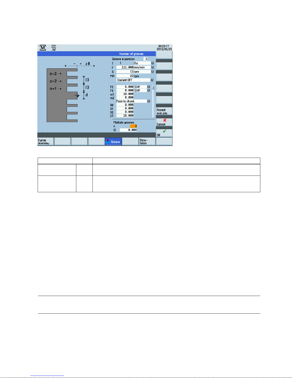
Programming and Operating Manual (Manual Machine Plus (MM+), Turning)
01/2017
45
As soon as you position the cursor in any of the input fields in the multiple grooves area of the screen, the display changes
from single groove to multiple grooves:
Parameter
Parameter
Description
Distance l3 Groove offset: This input value determines the offset between several identical grooves
during production.
Number n Number of grooves to be produced. Entering "0" or "1" here has the same effect: A single
groove is produced. When you enter a value of ">1", the appropriate number of grooves is
machined. The input value in parameter "Length I3" defines the necessary offset.
Multiple grooves
The machining sequence is as follows:
1. Starting from the current axis position, the first groove is produced as described for the extended grooving function.
2. The starting point for the next groove is then approached taking into account the clearance distance.
3. Another complete grooving cycle is then executed (as described for the extended grooving function).
4. Groove machining and offset then alternate until the number of grooves specified in the "Number n" parameter has been
executed.
5. On completion of the final groove, the original position of the axes before the start of machining is approached diagonally.
4.4.6
Manual thread cutting
Functionality
The manual thread cutting function provides a wide range of options for producing, remachining and recutting longitudinal,
tapered and face threads.
They can be single-start or multiple-start threads.
Note
Any limi
t stops that are activated should be disabled before starting thread cutting or set to a value outside the traversing
range needed for thread cutting.
Page 46
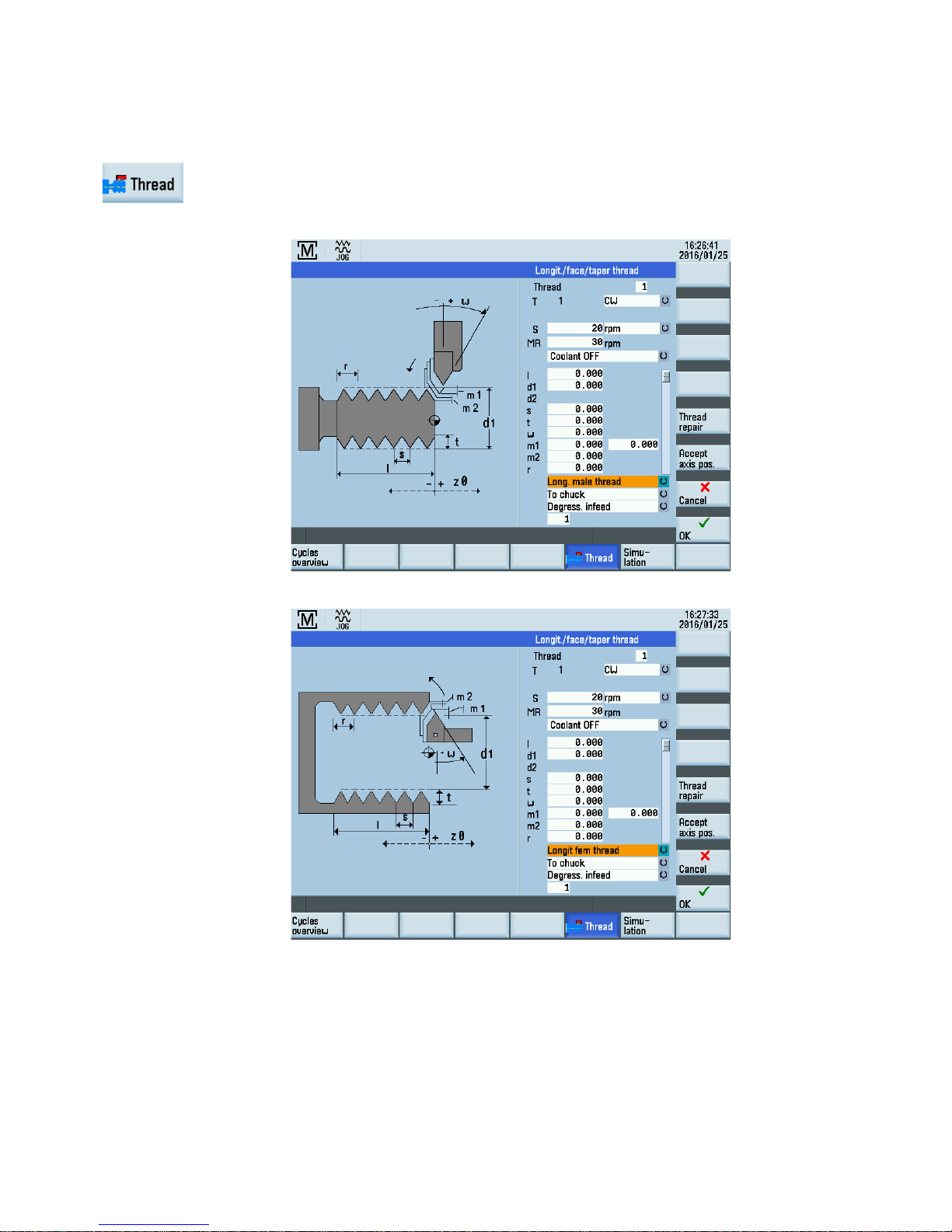
Programming and Operating Manual (Manual Machine Plus (MM+), Turning)
46 01/2017
4.4.6.1
Thread cutting
Operating sequences
1. You can access the manual thread cutting function by pressing this softkey in the main
screen f
or MM+.
Longitudinal male thread:
Longitudinal female thread:
Page 47
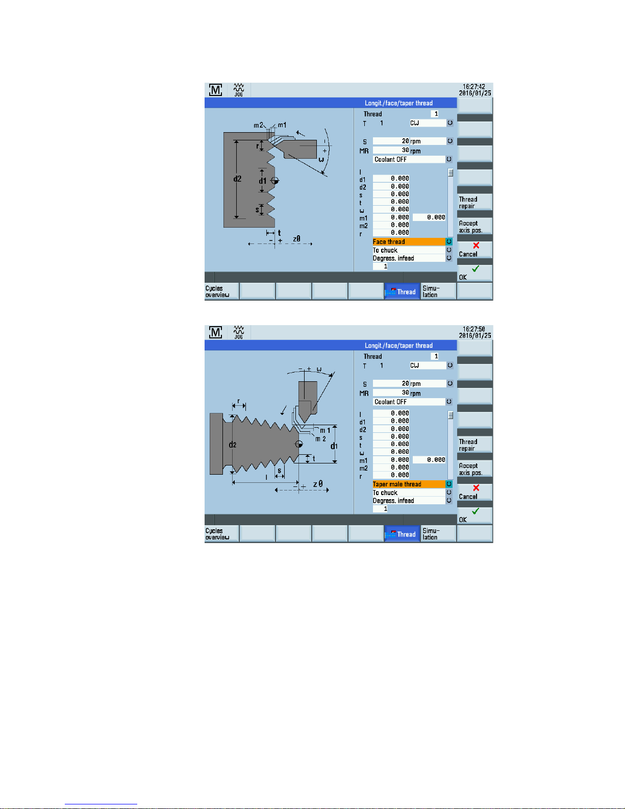
Programming and Operating Manual (Manual Machine Plus (MM+), Turning)
01/2017
47
Face thread:
Taper ma
le thread:
Page 48
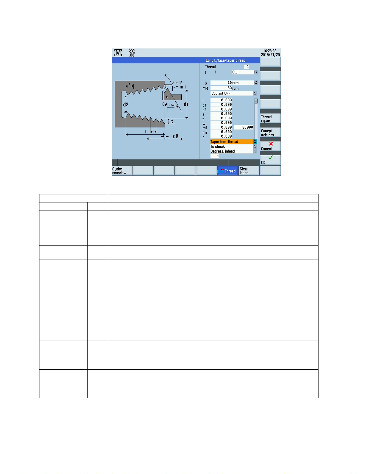
Programming and Operating Manual (Manual Machine Plus (MM+), Turning)
48 01/2017
Taper female threa
d:
Parameters
Parameter
Description
Reference
z0
Start position for the thread in the longitudinal axis (absolute position of the Z axis).
Thread length l Enter the length of the thread to be created, taking the start position for the thread ("Refer-
ence z0") as the starting point. The choice of whether to produce a left-hand or a right-hand
thread depends purely on the starting direction for the spindle.
Diameter Start d1 Start position for the thread in the transverse axis (absolute position of the X axis in the
diameter). This value applies in the reference point.
Diameter End d2 End position for the thread in the transverse axis (absolute position of the X axis in the di-
ameter).
Lead
s
Enter the required pitch in mm/rev.
Depth t This parameter is used to set the thread depth.
Note:
If the value of the displayed machine date 1108 equals 1 (requirement for automatically
calculating the thread depth) and the input field "t" equals 0, then the thread depth "t" will be
automatically calculated and entered when you enter the pitch value.
The following applies to all male threads:
• a thread pitch of 1 mm results in a thread depth of 0.613 mm
The following applies to all female threads:
• a thread pitch of 1 mm results in a thread depth of 0.541mm
The thread depth is adjusted according to an increase or reduction in the pitch value.
Infeed angle w Infeed angle; this specifies the angle of infeed during machining. A negative value causes
an alternating infeed.
Max. infeed depth
Min. infeed depth
m1 Enter here the maximum or minimum infeed depth for roughing. The cycle-internal infeed
calculation ensures that this entry value is not exceeded or falls short during thread cutting.
Finishing allowance
m2 Finishing allowance
Thread run-out
path
r Thread run-out path
Page 49
Programming and Operating Manual (Manual Machine Plus (MM+), Turning)
01/2017
49
Parameter
Description
Longitudinal internal thread/
longitudinal external thread/
face thread/
taper external thread/
taper internal thread
In this toggle field you can select whether an internal or an external thread is required. The
selection is indicated by a diagram on the screen.
To chuck/
From chuck
You can select the machining direction of the thread using this toggle field.
Number of thread starts
The number of thread starts is defined here.
Softkey
The above softkey is used to select remachining or thread recutting (thread repair).
Thread cutting
The machining sequence is as follows:
1. Starting from the current axis position, the start position for the thread (d1/z0) is approached in rapid traverse.
2. This is followed by infeed by the first depth of cut.
3. The controller then waits for the next zero mark from the spindle encoder in order to start the axis movements
(longitudinal axis and/or transverse axis) (depending on the thread geometry).
4. Once the end position for the thread has been reached in both axes, the tool is withdrawn from the workpiece in rapid
traverse.
5. The start position for the thread is then approached in the longitudinal and transverse axis in rapid traverse, observing a
clearance distance.
6. Infeed to the next depth of cut.
7. Wait for the next marker pulse from the spindle encoder to start the axes...
This process continues until all cuts have been completed. An additional finishing cut to smooth the thread is then
performed and the start position for the thread is approached in the longitudinal and transverse axes.
8. There is now a choice of two options:
– Machining is now complete and the execution screen can be closed with the following softkey:
– If you wish to continue machining the thread, for example, if thread finishing is required, press the following hardkey
again:
4.4.6.2
Thread recutting
Functionality
The thread recutting function is a subfunction of "Manual thread cutting". It can be used to recut a thread or to continue
machining the thread on a workpiece that has been unclamped in between.
To make thread recutting to proceed correctly, you have to enter the appropriate values in the thread cutting screen form.
Page 50
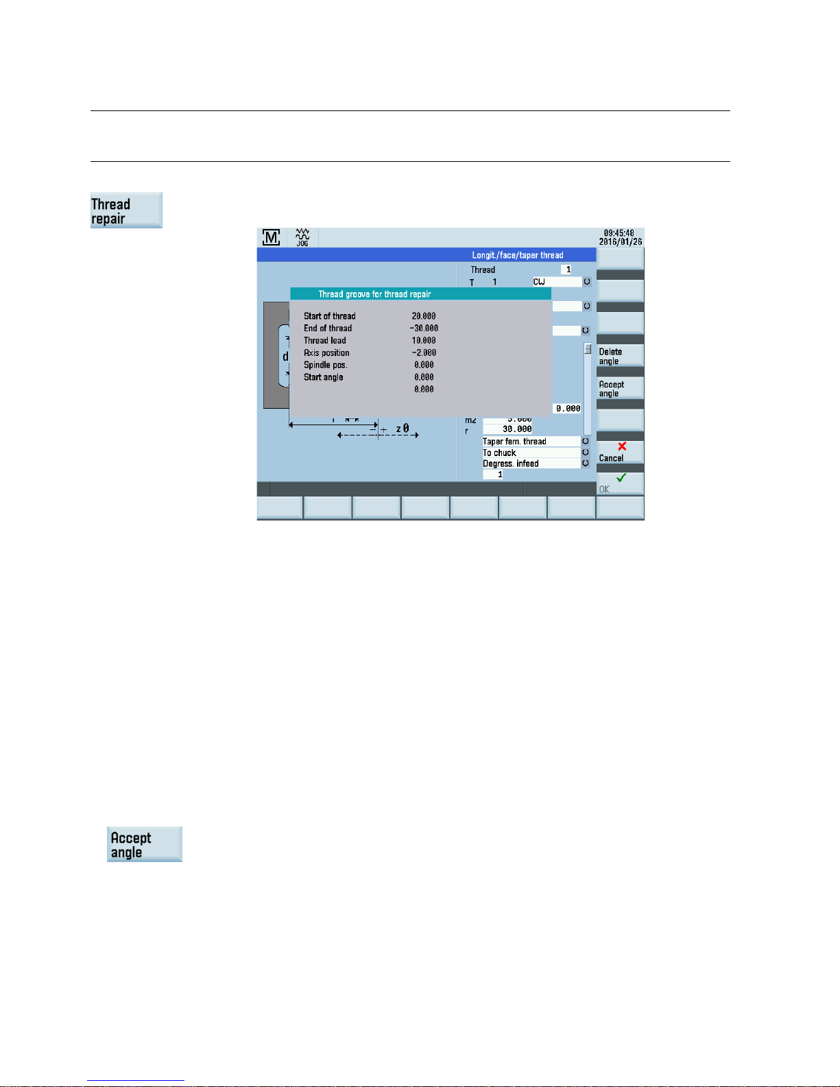
Programming and Operating Manual (Manual Machine Plus (MM+), Turning)
50 01/2017
Operating sequences
Note
The thread recutting function uses the entry values from the thread cutting screen form. This screen form must therefore
have been completed so that thread cutting can proceed correctly.
1. You can call the thread recutting function with this s
oftkey.
The following screen form appears:
The values displayed for start of thread, end of thread and axis position relate to the type of
thread selected.
Longitudinal and taper thread
≤ 45° (Z axis)
Face and taper thread ≤ 45° (X axis)
All values displayed on this screen form are for information only; it is not, therefore, possible
to alter them directly.
Execute thread recut
The following requirements must be fulfilled before you can recut a thread:
● Appropriate values must already have been entered in the thread cutting screen form at this point.
● The screen above is displayed.
● The spindle must be stationary (switched off) and must already have been synchronized, in other words, it must have
been turned through at least one full revolution since the controller was last powered up; otherwise, an error message
appears when the thread angle is accepted.
● Now use the handwheels to traverse the axes until the thread cutting tool can be threaded into the existing thread.
● Carefully introduce the tool into the thread. The axis position value shown on the screen must be between the values for
the thread initial position and thread end position.
● Press the above softkey. The current spindle angle is now converted into the appropriate starting angle offset for thread
cutting. The starting angle that is now displayed corresponds to the angle that will subsequently be used as the starting
angle offset for machining a right-hand or left-hand thread.
● Using the handwheels, move the axes into a position from which the start of the thread can be approached safely.
Page 51
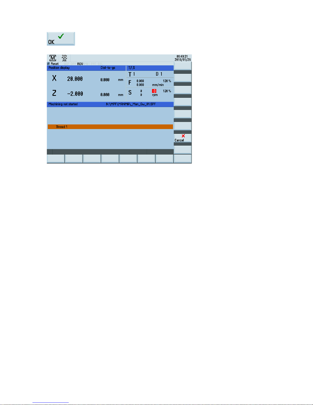
Programming and Operating Manual (Manual Machine Plus (MM+), Turning)
01/2017
51
● Press the above softkey and the following screen appears:
The rest of the thread cutting process is exactly the same as that described for the manual thread cutting function.
The only difference is that thread cutting is not started with the marker pulse from the spindle encoder but with the angle that
was calculated in the previous screen for thread repair (thread recutting) as the start angle offset.
4.4.7
Roughing cycles
Functionality
The roughing cycles (integrated in the control) are the easiest way of producing common paraxial cutting contours. They are
defined by setting particular input parameters in the appropriate screen forms.
The contour can be machined using the following position of the contour:
● Outside right
● Inside right
● Outside left
Roughing is either longitudinal or planar.
Page 52
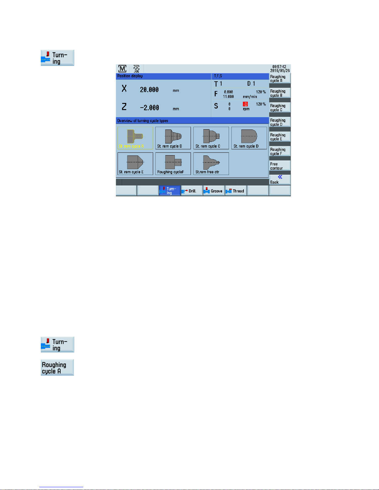
Programming and Operating Manual (Manual Machine Plus (MM+), Turning)
52 01/2017
Operating sequences
1. Starting from the main menu for MM+ you can reach the roughing cycle functions via this
softkey.
The following roughing cycles can be used via the vertical softkey bar or by choosing via cursor keys:
● Roughing cycle A - simple stepped contour
● Roughing cycle B - expanded stepped contour with beveled edges
● Roughing cycle C - expanded stepped contour with rounding
● Roughing cycle D - single radius
● Roughing cycle E - single taper
● Roughing cycle F - Face and longitudinal turning
● Roughing cycle - free contour
4.4.7.1
Roughing cycle A
Functionality
The roughing cycle A function is used to produce a simple stepped contour (step), with the option of working the transitions
to adjacent faces as a radius or chamfer.
Operating sequences
1. You can access the turning cycle o
verview by pressing this softkey in the basic screen for
MM+.
2. In the displayed screen, press this softkey.
Page 53
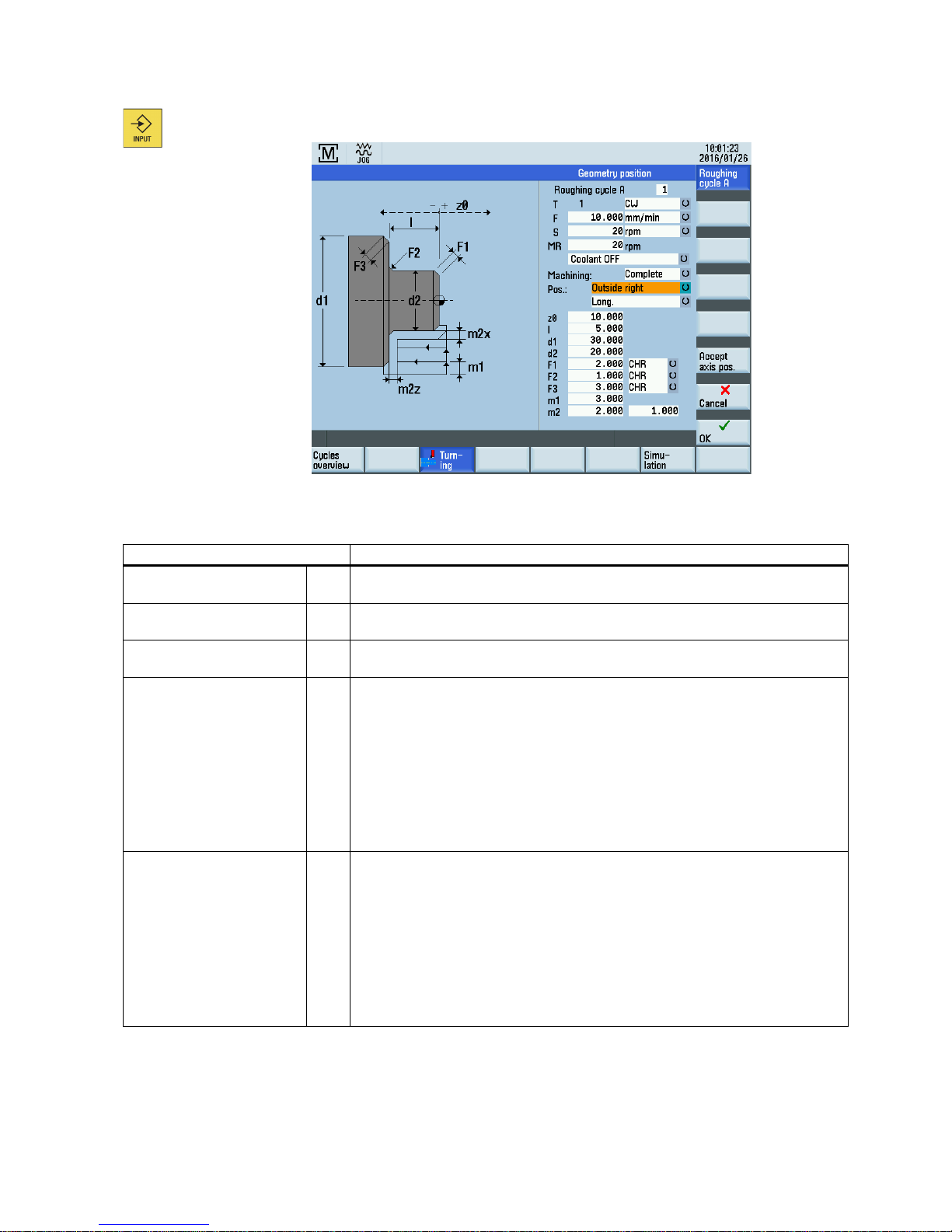
Programming and Operating Manual (Manual Machine Plus (MM+), Turning)
01/2017
53
Alternatively, you can select this function from the turning cycle overview with cursor keys
and activate it with this hardkey.
Input fields
The input fields in the roughing cycle A screen form have the following meanings:
Parameter
Description
Length l Enter the length of the "step" to be produced, taking the contour start position
("Reference z0") in the axial axis (Z axis) as the starting point.
Diameter d1 Outside diameter of the "step" to be machined in the radial axis (absolute position
of the X axis in the diameter).
Diameter d2 Inside diameter of the "step" to be machined in the radial axis (absolute position of
the X axis in the diameter).
Chamfer/radius F1 Depending on the option selected, this value forms either a transition radius (dis-
play "RND") or a transition chamfer (display "CHR" or "CHF") of less than 45
0
between the end face and the inside diameter of the "step". You can toggle between
RND/CHR/CHF using the toggle key. An input value of 0.0 switches this function
off.
Two types of dimensioning are possible with the chamfers:
• in the case of chamfer CHR, the value specifies the width of the chamfer in the
direction of the movement,
• in the case of chamfer CHF, the value corresponds with the length of the cham-
fer.
Chamfer/radius F2 Depending on the option selected, this value forms either a transition radius (dis-
play "RND") or a transition chamfer (display "CHR" or "CHF") of less than 45
0
between the end face and the inside diameter of the "step". You can toggle between
RND/CHR/CHF using the toggle key. An input value of 0.0 switches this function
off.
Two types of dimensioning are possible with the chamfers:
• in the case of chamfer CHR, the value specifies the width of the chamfer in the
direction of the movement,
• in the case of chamfer CHF, the value corresponds with the length of the cham-
fer.
Page 54
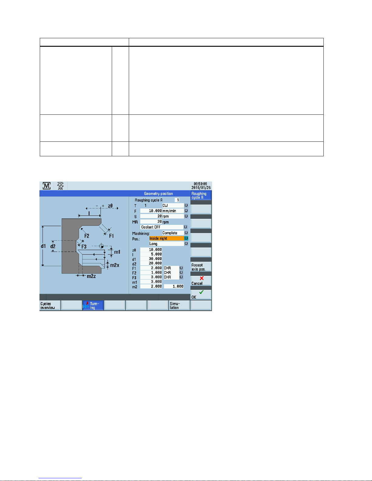
Programming and Operating Manual (Manual Machine Plus (MM+), Turning)
54 01/2017
Parameter
Description
Chamfer/radius F3 Depending on the option selected, this value forms either a transition radius (dis-
play "RND") or a transition chamfer (display "CHR" or "CHF") of less than 45
0
between the end face and the inside diameter of the "step". You can toggle between
RND/CHR/CHF using the toggle key. An input value of 0.0 switches this function
off.
Two types of dimensioning are possible with the chamfers:
• in the case of chamfer CHR, the value specifies the width of the chamfer in the
direction of the movement,
• in the case of chamfer CHF, the value corresponds with the length of the cham-
fer.
Max. infeed depth m1 Enter the maximum infeed depth for roughing. The internal infeed calculation en-
sures that the infeed is as uniform as possible throughout the roughing operation.
This entry value represents the maximum value possible and is therefore not ex-
ceeded.
Finishing allowance m2 Finishing allowance in the X axis (m2x)
Finishing allowance in the Z axis (m2z)
The following possibilities exist for the position of the geometry:
Inside right:
Page 55
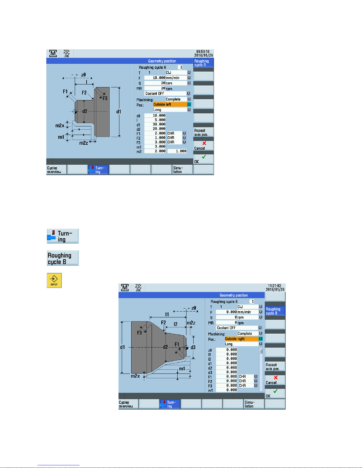
Programming and Operating Manual (Manual Machine Plus (MM+), Turning)
01/2017
55
Outside left:
4.4.7.2
Roughing cycle B
Functionality
The roughing cycle B function is used to produce a simple cutting contour, with an additional interpolation point allowing
beveled or tapered contours. Transitions to adjacent faces can again be worked as a radius or chamfer.
Operating sequences
1. You can access the turning cycle overview by pressing this softkey in the basic screen for
MM+.
2. In the displayed screen, press this softkey.
Alternatively, you can select this function from the turning cycle overview with cursor keys
and
activate it with this hardkey.
Page 56

Programming and Operating Manual (Manual Machine Plus (MM+), Turning)
56 01/2017
Input fields
The input fields in the roughing cycle B screen form have the following meanings:
Parameter
Description
Length l1 Enter the length of the "step" to be produced, taking the contour start position ("Reference
z0") in the axial axis (Z axis) as the starting point.
Length l2 Interpolation point position, which defines the position of the additional contour interpolation
point in the longitudinal axis (Z axis).
Diameter d1 Outside diameter of the "step" to be machined in the radial axis (absolute position of the X
axis in the diameter).
Diameter d2 Interpolation point diameter, which together with the "Interpolation point position l2" parame-
ter defines the position of the interpolation point in the radial axis (absolute position of the X
axis in the diameter), allowing beveled faces to be produced within a "step".
Diameter d3 Inside diameter of the "step" to be machined in the radial axis (absolute position of the X
axis in the diameter).
Chamfer/radius F1 Depending on the option selected, this
value forms either a transition radius (display "RND")
or a transition chamfer (display "CHR" or "CHF") of less than 450 between the end face and
the inside diameter of the "step". You can toggle between RND/CHR/CHF using the toggle
key. An input value of 0.0 switches this function off.
Two types of dimensioning are possible with the chamfers:
• in the case of chamfer CHR, the value specifies the width of the chamfer in the direction
of the movement,
• in the case of chamfer CHF, the value corresponds with the length of the chamfer.
Chamfer/radius F2
Depending on the option selected, this value forms either a transition radius (display "RND")
or a transition chamfer (display "CHR" or "CHF") of less than 450 between the end face and
the inside diameter of the "step". You can toggle between RND/CHR/CHF using the toggle
key. An input value of 0.0 switches this function off.
Two types of dimensioning are possible with the chamfers:
• in the case of chamfer CHR, the value specifies the width of the chamfer in the direction
of the movement,
• in the case of chamfer CHF, the value corresponds with the length of the chamfer.
Chamfer/radius F3
Depending on the option selected, this value forms either a transition radius (display "RND")
or a transition chamfer (display "CHR" or "CHF") of less than 450 between the end face and
the inside diameter of the "step". You can toggle between RND/CHR/CHF using the toggle
key. An input value of 0.0 switches this function off.
Two types of dimensioning are possible with the chamfers:
• in the case of chamfer CHR, the value specifies the width of the chamfer in the direction
of the movement,
•
in the case of chamfer CHF, the value corresponds with the length of the chamfer.
Max. infeed depth m1 Enter the maximum infeed depth for roughing. The internal infeed calculation ensures that
the infeed is as uniform as possible throughout the roughing operation. This entry value
represents the maximum value possible and is therefore not exceeded.
Finishing allow-
ance
m2 Finishing allowance in the X axis (m2x)
Finishing allowance in the Z axis (m2z)
Page 57
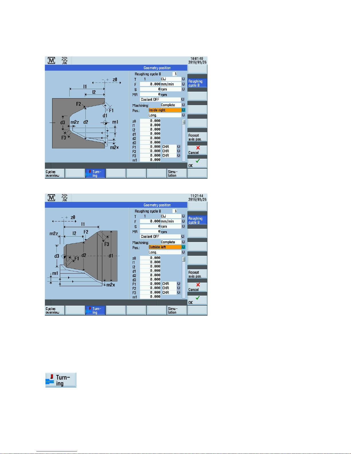
Programming and Operating Manual (Manual Machine Plus (MM+), Turning)
01/2017
57
The following possibilities exist for the position of the geometry:
Inside right:
Outside left:
4.4.7.3
Roughing cycle C
Functionality
The roughing C function is used to produce a special cutting contour, with a filleted transition between the inside and outside
diameter of the contour. Other chamfers or radii cannot be included.
Operating sequences
1. You can access the turning cycle overview by pressing this softkey in the basic screen for
MM+.
Page 58
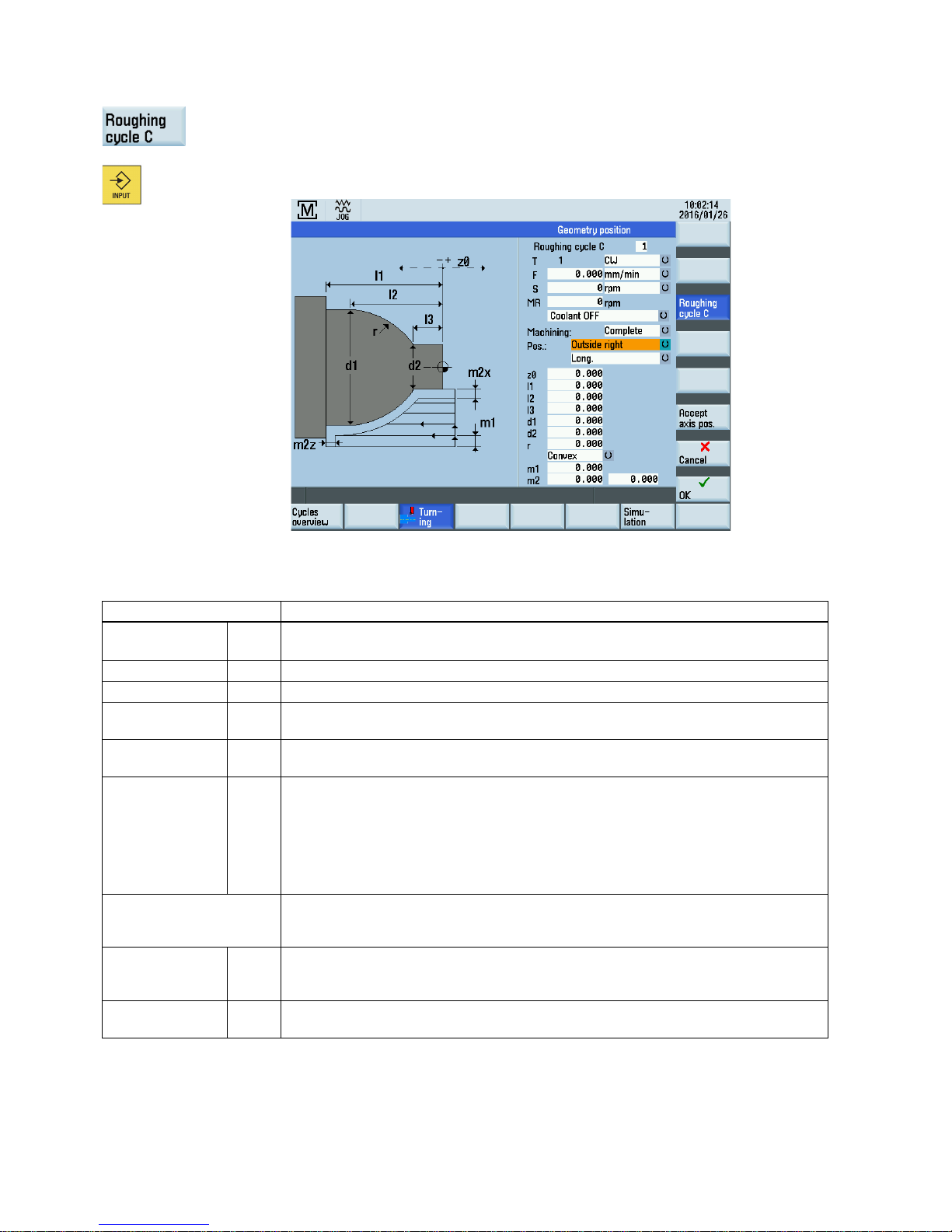
Programming and Operating Manual (Manual Machine Plus (MM+), Turning)
58 01/2017
2. In the displayed screen, press this softkey.
Alternatively, you can select this function from the turning cycle overview with cursor keys
and activate it with this hardkey.
Input fields
The input fields in the roughing cycle C screen form have the following meanings:
Parameter
Description
Length l1 Enter the end point of the contour in the axial axis here, taking the contour start position
("Reference z0") in the axial axis (Z axis) as the starting point.
Length
l2
End point of filleting in the longitudinal axis (Z axis).
Length l3 Start point of filleting in the longitudinal axis (Z axis).
Diameter d1 Outside diameter of the "step" to be machined in the radial axis (absolute position of the X
axis in the diameter).
Diameter d2 Inside diameter of the "step" to be machined in the radial axis (absolute position of the X
axis in the diameter).
Radius r This entry value determines the size of the filleting, the center of the circle being calculated
internally. It is located on the imaginary line that is central and "normal" (90
o
) to the imaginary connecting line between points "l2/d1" and "l3/d2". The choice of whether the center
point is on the side of the contour facing towards or away from the turning center is determined by the "convex/concave" function key setting. If the radius entered is too small, an
error message will be displayed during machining (after a cycle start) since the contour
cannot be produced in this case.
Convex/concave This toggle key is used to specify on which side of the contour the circle center point should
be located. The circular machining direction, and hence the appearance of the finished
contour, is adjusted accordingly.
Max. infeed depth m1 Enter the maximum infeed depth for roughing. The internal infeed calculation ensures that
the infeed is as uniform as possible throughout the roughing operation. This entry value
represents the maximum value possible and is therefore not exceeded.
Finishing allow-
ance
m2 Finishing allowance in the X axis (m2x)
Finishing allowance in the Z axis (m2z)
Page 59
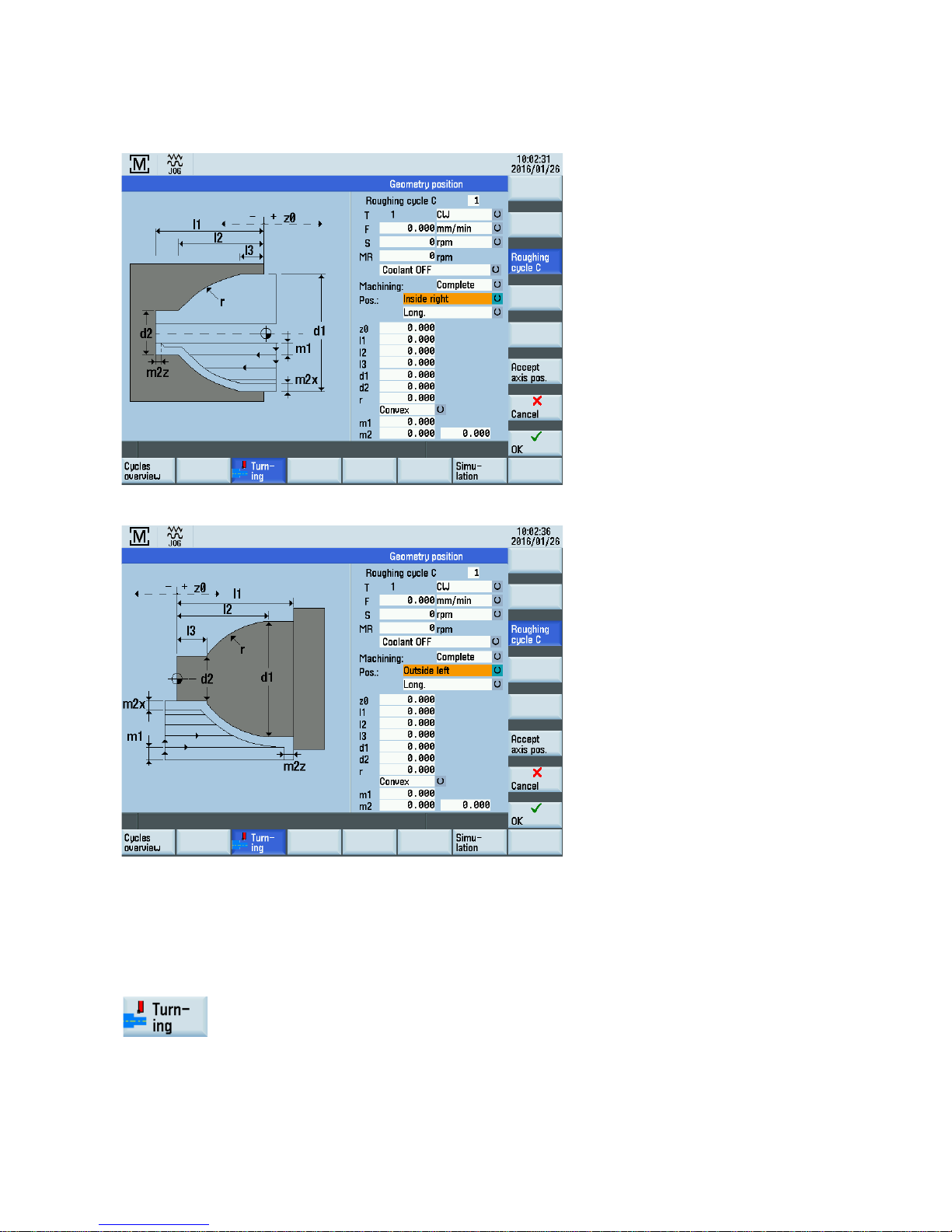
Programming and Operating Manual (Manual Machine Plus (MM+), Turning)
01/2017
59
The following possibilities exist for the position of the geometry:
Inside right:
Outside left:
4.4.7.4
Roughing cycle D
Functionality
The roughing cycle D function allows a single radius contour to be machined, supported by cycles.
Operating sequences
1. You can access the turning cycle overview by pressing this softkey in the basic screen for
MM+.
Page 60
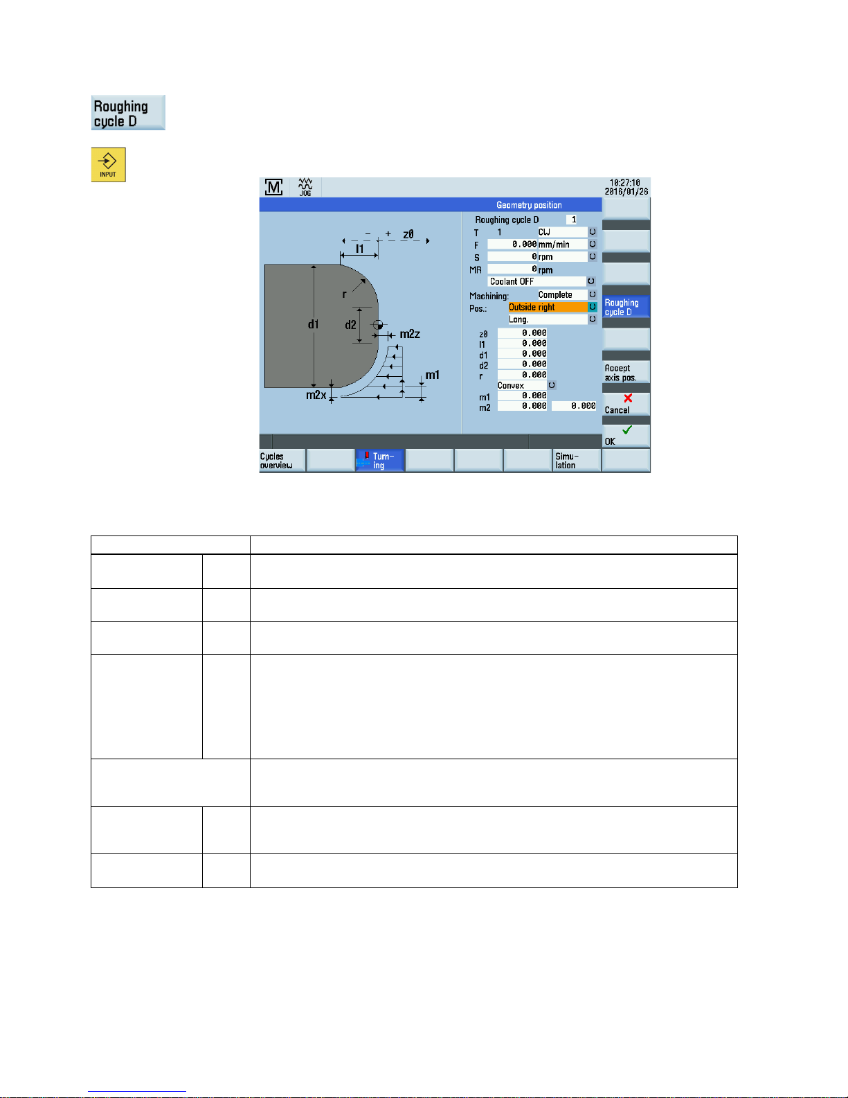
Programming and Operating Manual (Manual Machine Plus (MM+), Turning)
60 01/2017
2. In the displayed screen, press this softkey.
Alternatively, you can select this function from the turning cycle overview with cursor keys
and activate it with this hardkey.
Input fields
The input fields in the roughing cycle D screen form have the following meanings:
Parameter
Description
Length l1 Enter the end point of the contour in the axial axis here, taking the contour start position
("Reference z0") in the axial axis (Z axis) as the starting point.
Diameter d1 Outside diameter of the contour to be machined in the transverse axis (absolute position of
the X axis in the diameter).
Diameter d2 Inside diameter of the "radius" to be machined in the radial axis (absolute position of the X
axis in the diameter).
Radius R This input value determines the size of the radius, the center of the circle being calculated
internally. It is located on the imaginary line that is central and "normal" (90
0
) to the imaginary connecting line between points "(Z0-l1)/d1" and "Z0/d2". The choice of whether the
center point is on the side of the contour facing towards or away from the turning center is
determined by the "convex/concave" function key setting. If the radius entered is too small,
an error message will be displayed during machining (after a cycle start) since the contour
cannot be produced in this case.
Convex/concave This toggle key is used to specify on which side of the contour the circle center point should
be located. The circular machining direction, and hence the appearance of the finished
contour, is adjusted accordingly.
Max. infeed depth m1 Enter the maximum infeed depth for roughing. The internal infeed calculation ensures that
the infeed is as uniform as possible throughout the roughing operation. This entry value
represents the maximum value possible and is therefore not exceeded.
Finishing allow-
ance
m2 Finishing allowance in the X axis (m2x)
Finishing allowance in the Z axis (m2z)
Page 61
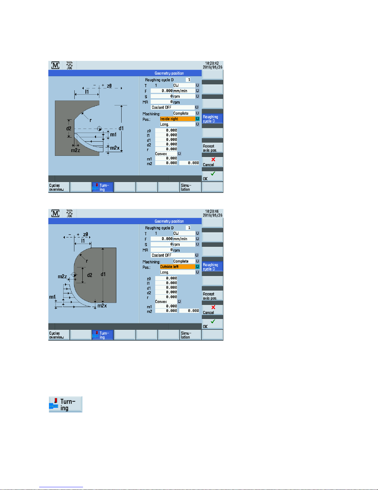
Programming and Operating Manual (Manual Machine Plus (MM+), Turning)
01/2017
61
The following possibilities exist for the position of the geometry:
Inside right:
Outside left:
4.4.7.5
Roughing cycle E
Functionality
The roughing cycle E function allows a single taper contour to be machined, supported by cycles.
Operating sequences
1. You can access the turning cycle overview by pressing this softkey in the basic screen for
MM+.
Page 62
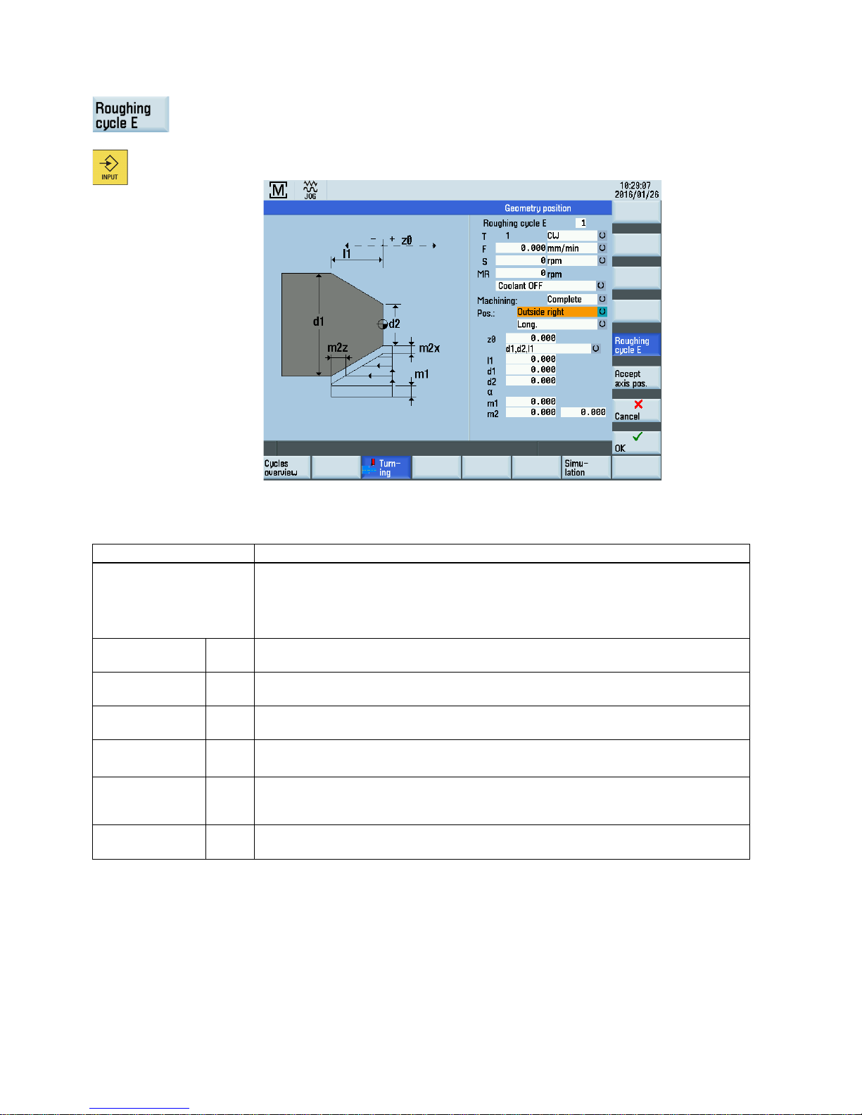
Programming and Operating Manual (Manual Machine Plus (MM+), Turning)
62 01/2017
2. In the displayed screen, press this softkey.
Alternatively, you can select this function from the turning cycl
e overview with cursor keys
and activate it with this hardkey.
Input fields
The input fields in the roughing cycle E screen form have the following meanings:
Parameter
Description
d1, d2,... The dimensioning type can be selected in this toggle field.
The following options are available:
"d1,d2,l1" -> "d1,l1,angle" -> "d2,l1,angle" -> "d1,d2,angle(d1)" -> "d1,d2,angle(d2)"
The selection is indicated in the diagram displayed on the screen.
Length l1 Enter the length of the taper to be produced, taking the contour start position ("Reference
z0") in the axial axis (Z axis) as the starting point.
Diameter d1
Outside diameter of the taper to be machined in the transverse axis (absolute position of the
X axis in the diameter).
Diameter d2 Inside diameter of the taper to be machined in the transverse axis (absolute position of the
X axis in the diameter).
Angle α Angle of the taper to be machined.
The reference point is either d1 or d2 depending on which dimensioning type is selected.
Max. infeed depth m1 Enter the maximum infeed depth for roughing. The internal infeed calculation ensures that
the infeed is as uniform as possible throughout the roughing operation. This entry value
represents the maximum value possible and is therefore not exceeded.
Finishing allow-
ance
m2 Finishing allowance in the X axis (m2x)
Finishing allowance in the Z axis (m2z)
Page 63
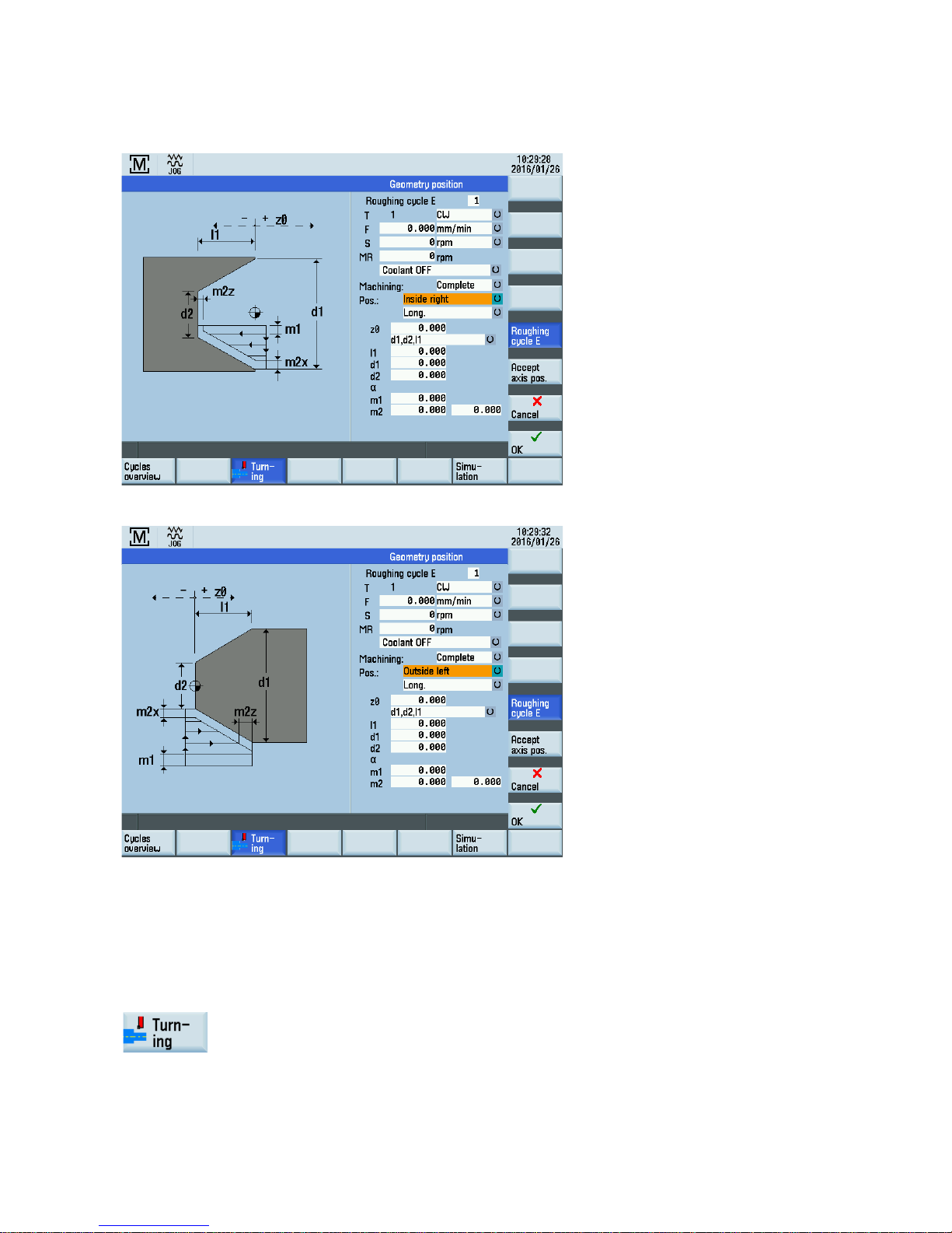
Programming and Operating Manual (Manual Machine Plus (MM+), Turning)
01/2017
63
The following possibilities exist for the position of the geometry:
Inside right:
Outside left:
4.4.7.6
Roughing cycle F
Functionality
The roughing cycle F function allows cycle-supported production of an end face (cutting direction is planar) or of a peripheral
surface (cutting direction is longitudinal).
Operating sequences
1. You can access the turning cycle overview by pressing
this softkey in the basic screen for
MM+.
Page 64
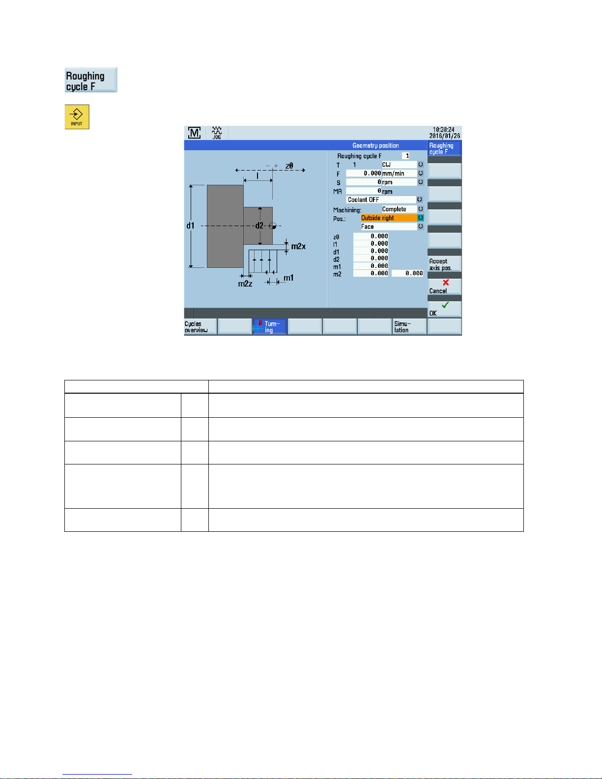
Programming and Operating Manual (Manual Machine Plus (MM+), Turning)
64 01/2017
2. In the displayed screen, press this softkey.
Alternatively, you can select this function from the turning cycle overview with cursor keys
and activate it with this hardkey.
Input fields
The input fields in the "Roughing F" screen form have the following meanings:
Parameter
Description
Length l Enter here the length of the end face to be cut, taking the contour start position
("Reference z0") in the longitudinal axis (Z axis) as the starting point.
Diameter d1 External diameter of the end face to be cut (absolute position of the X axis in the
diameter).
Diameter d2 Internal diameter of the end face to be cut (absolute position of the X axis in the
diameter).
Max. infeed depth m1 Enter the maximum infeed depth for roughing. The internal infeed calculation en-
sures that the infeed is as uniform as possible throughout the roughing operation.
This entry value represents the maximum value possible and is therefore not ex-
ceeded.
Finishing allowance m2 Finishing allowance in the X axis (m2x)
Finishing allowance in the Z axis (m2z)
Page 65
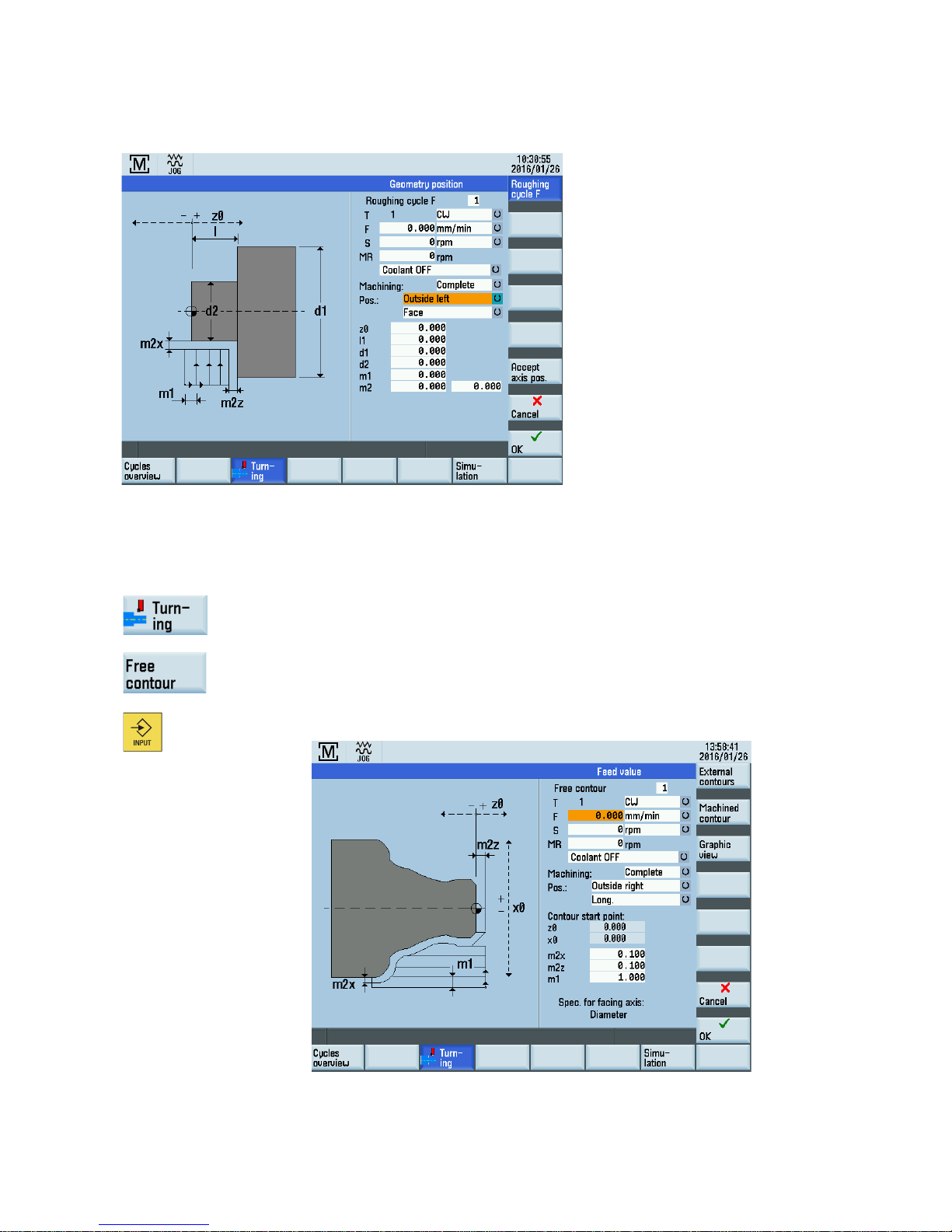
Programming and Operating Manual (Manual Machine Plus (MM+), Turning)
01/2017
65
The following option is available for the position of the geometry:
Outside left:
4.4.7.7
Roughing cycle, free contour
Functionality
The free contour cycle function is used for the input and for the processing of an arbitrary contour path.
Operating sequences
1. You can access the turning cycle overview by pressing this softkey in the basic screen for
MM+.
2. In the displayed scree
n, press this softkey.
Altern
atively, you can select this function from the turning cycle overview with cursor keys
and activate it with this hardkey.
Page 66
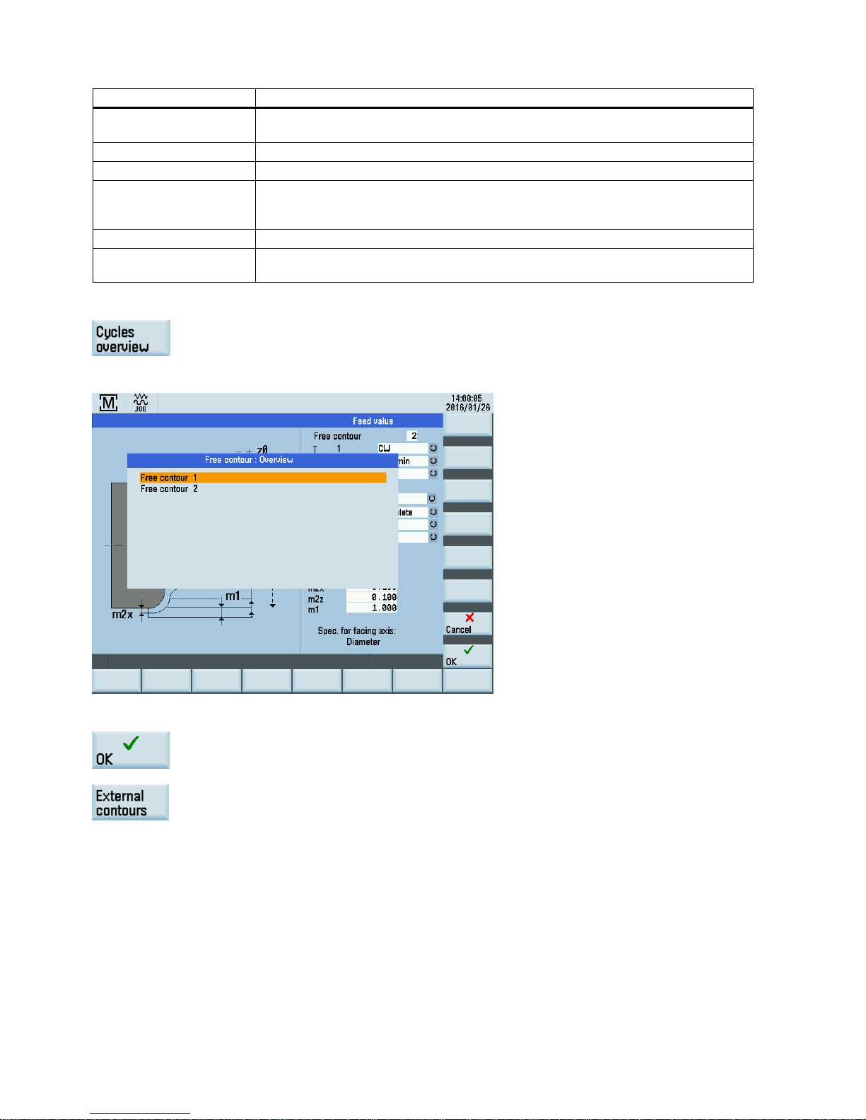
Programming and Operating Manual (Manual Machine Plus (MM+), Turning)
66 01/2017
Parameter
Description
x0
Outside diameter of the shaft to be machined in the transverse axis (absolute position of the
X axis in the diameter).
m2x
Finishing allowance horizontal to the contour.
m2z
Finishing allowance perpendicular to the contour.
m1 Enter the maximum infeed depth for roughing. The internal infeed calculation ensures that
the infeed is as uniform as possible throughout the roughing operation. This entry value
represents the maximum value possible and is therefore not exceeded.
NAME
If an external contour has been selected, the path to the contour program is shown here.
Specification for transverse
axis
The selected specification is displayed.
Softkeys
The cycle overview function lists all free contours contained in the machining step program.
To choose, place the cursor on the appropriate line and press the following softkey:
It is also possible to assign a contour of an external contour subroutine to the cycle.
Page 67
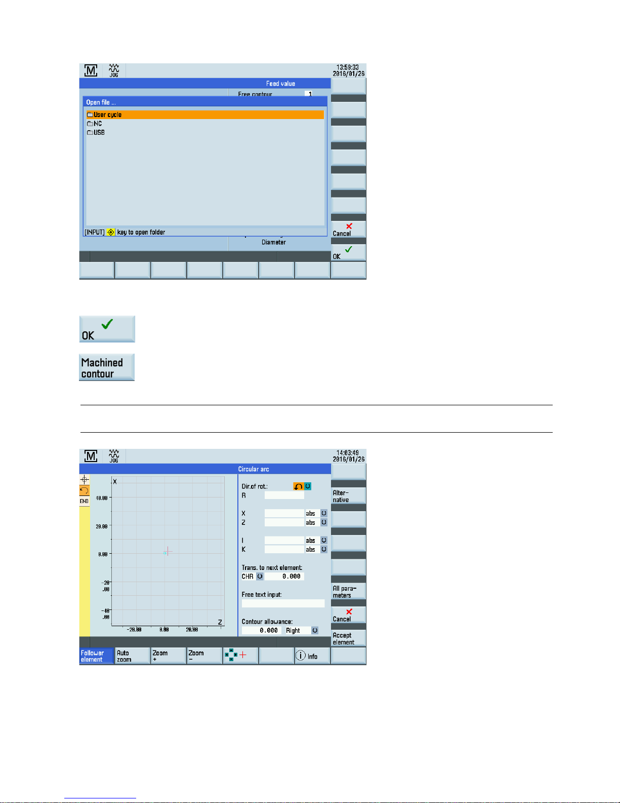
Programming and Operating Manual (Manual Machine Plus (MM+), Turning)
01/2017
67
This function opens a dialog box with which the contour subroutine can be selected. Pressing the following softkey links the
selected program with the cycle:
The machined contour function branches to the contour input.
Note
Only contours listed in the cycle overview can be machined. External contours cannot be machined.
First, define the contour starting point.
Page 68
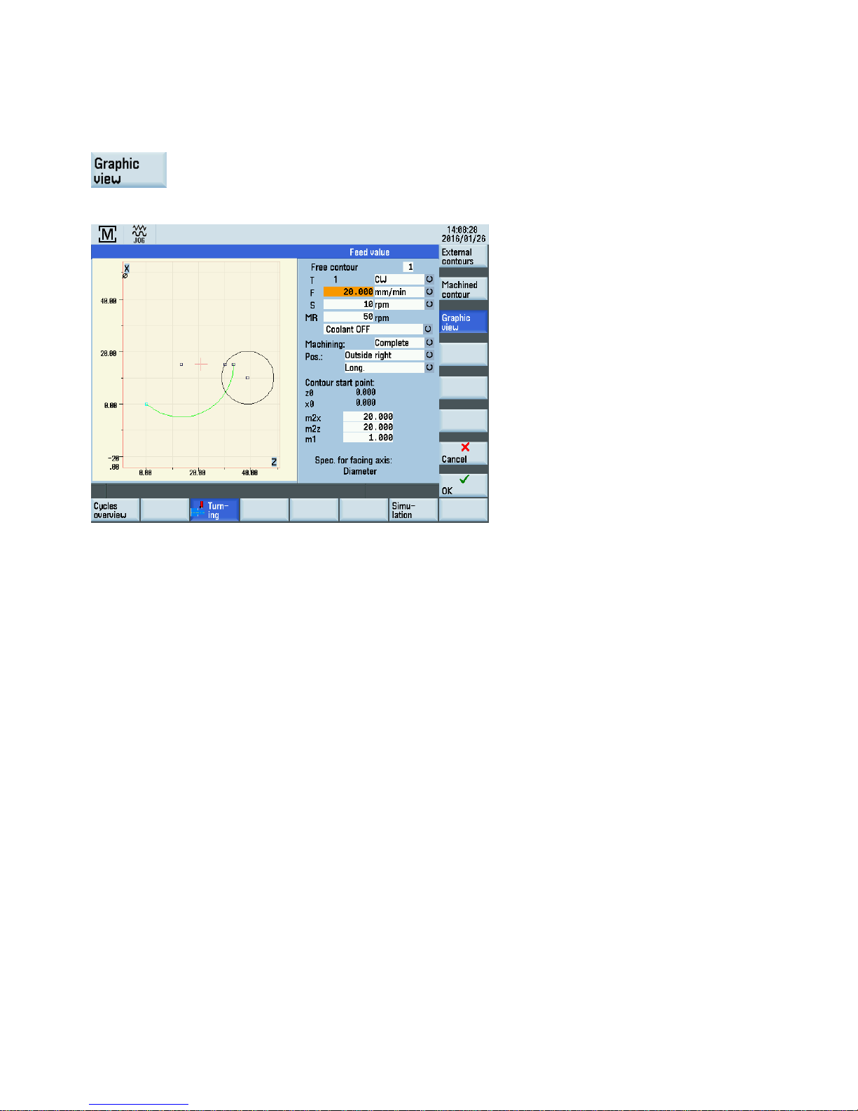
Programming and Operating Manual (Manual Machine Plus (MM+), Turning)
68 01/2017
References
For more information on the machined contour function, see Section "Defining a start point" of the SINUMERIK
808D/SINUMERIK 808D ADVANCED Programming and Operating Manual (Turning).
Rather than the auxiliary chart, this function displays the entered contour section.
4.4.7.8
Execute a roughing cycle
Rough cutting
Starting from the current axis position, the rough cutting sequence is as follows:
1. Diagonal approach to the start position calculated in the cycle in both axes.
The safety clearance and finishing allowance are taken into account.
2. Infeed in the infeed axis (transverse axis or longitudinal axis, depending on whether the planar or longitudinal cutting
direction was selected).
The infeed is calculated within the cycle as follows:
– The input value "m1" is not exceeded.
– The infeed quantity is guaranteed to remain constant until the unmachined contour is reached (taking finishing
allowance into account).
3. Execution of the paraxial roughing motion in the cutting axis until the unmachined contour is reached.
The finishing allowance is taken into account.
4. Withdrawal from the material in the infeed axis by the infeed distance.
5. Retraction by the clearance distance below 45° in both axes.
6. Return in the cutting axis to the start position calculated in the cycle.
7. New infeed in the infeed axis by the infeed depth calculated in the cycle.
All roughing cuts are performed one after another, as described above.
Page 69
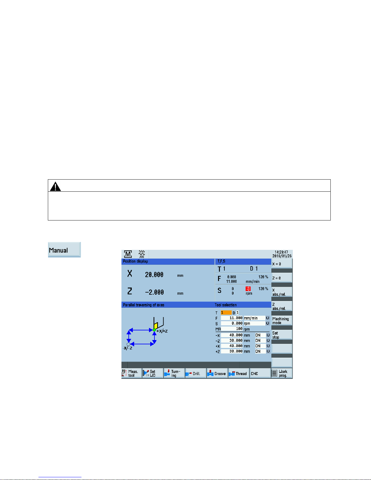
Programming and Operating Manual (Manual Machine Plus (MM+), Turning)
01/2017
69
Finish cutting
When the final rough cut is completed, the contour is finish cut with the following motions:
1. Traverse in the infeed axis to the finished dimension for the contour, corrected by the clearance distance.
2. Infeed in both axes (below 45°) to the contour start point.
3. Execution of the finishing motion along the parameterized contour.
4. Retraction by the clearance distance below 45° in both axes.
5. Return in the cutting axis to the start position calculated in the cycle.
6. Finally, the original position of the axes before the start of machining is approached diagonally.
5
Machining the machining step program manually
Functionality
The machining step program function can be used to define a list containing an optional sequence of machining cycles.
This list can then be automatically machined step by step.
The controller can store a maximum of 390 steps.
WARNING
Danger to life and/or damage to machine due to insecure part programs
Running an insecure part program on your machine may cause unexpected attacks to the machine, which in turn can lead
to death, personal injuries, and/or machine damage.
•
Make sure you use part programs that come from trusted sources.
Operating sequences
1. Press this softkey to access the basic screen for MM+.
Page 70
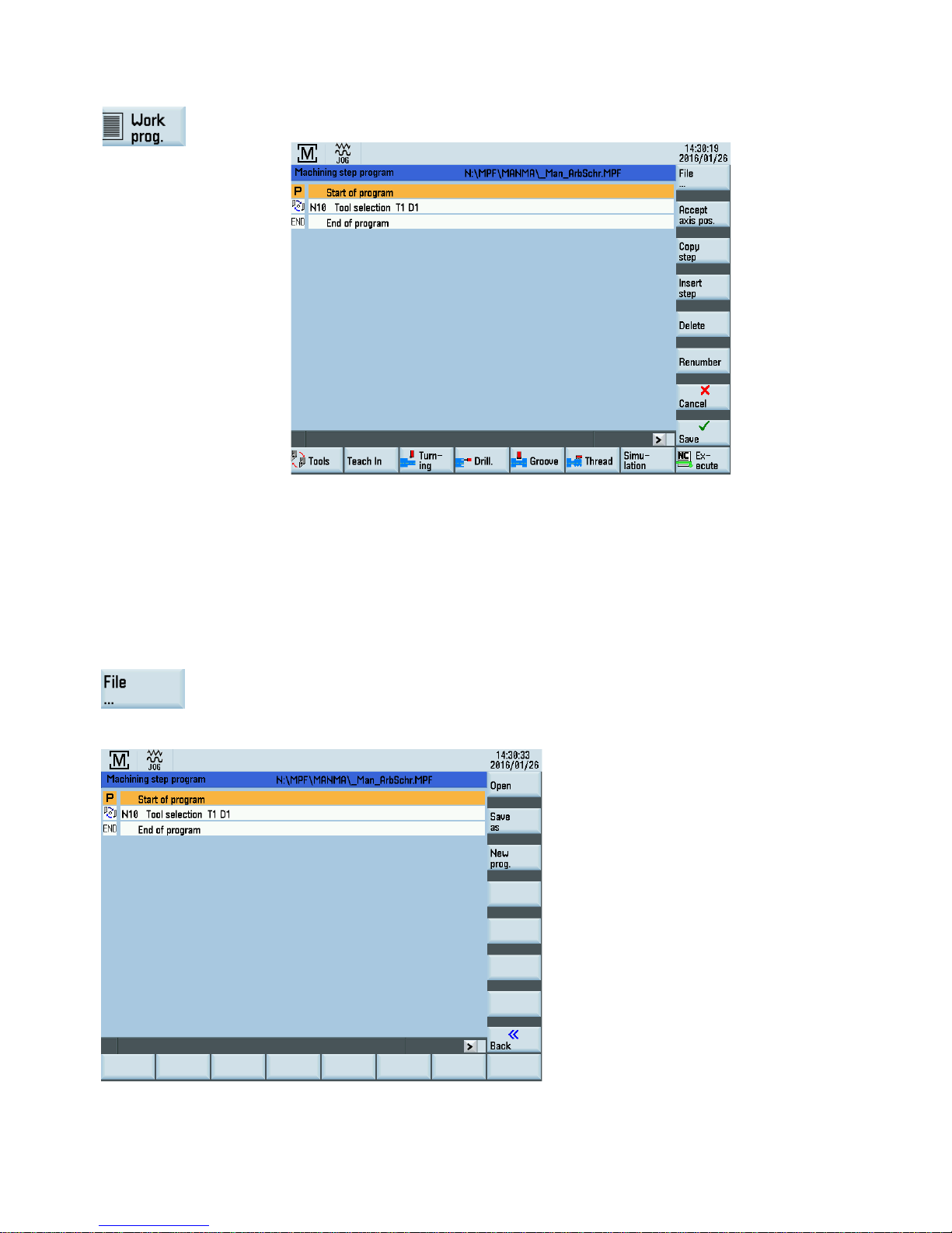
Programming and Operating Manual (Manual Machine Plus (MM+), Turning)
70 01/2017
2. You can access the screen for input into the list by pressing this softkey in the main screen
for MM+.
Screen handling functions
● To select machine steps, press the <cursor up> or <cursor down> key on the PPU. The selected step is displayed on an
orange background.
● If you have selected a machining cycle, the input screen for this cycle or the taught block opens automatically when you
press the <cursor right> key.
Softkeys
Other inputs in the screen are made with softkeys:
Opens the following dialog box:
Page 71
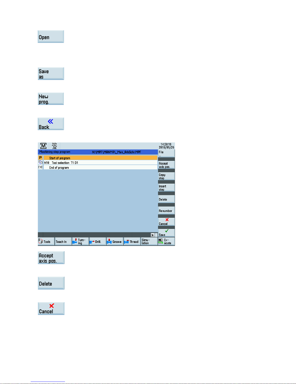
Programming and Operating Manual (Manual Machine Plus (MM+), Turning)
01/2017
71
Displays a dialog used to open an existing machining step program or create a new machining step program.
If the file is not located in drive N (control system storage), ensure that the external medium is not removed during the
machining.
Displays a save dialog.
Displays a dialog used to create a program.
Returns to the menu for the machining step program
Inserts a positioning block at the current machine axis position in the selected machining step.
Deletes the currently selected machining step.
Interrupts the machining step program function.
This softkey returns you to the main screen for MM+.
If you have changed any values, a prompt window informs you accordingly.
Page 72
Programming and Operating Manual (Manual Machine Plus (MM+), Turning)
72 01/2017
: Press it to save the values.
: Press it to discard the settings.
Saves the machining step program.
This softkey returns you to the main screen for MM+.
Inserts a tool change into the program.
This softkey shows you the dialog box for Tool change in the machining step program (Page 73).
Inserts a traversing block in the program.
Inserts a roughing cycle in the program.
This softkey shows you the dialog box for Roughing cycles (Page 51).
Inserts a drilling cycle in the program.
This softkey shows you the dialog box for the Manual thread tapping (Page 35).
Inserts a groove/cutting cycle into the program.
This softkey shows you the dialog box for the Manual grooving/parting (Page 37).
Inserts a thread cycle.
This softkey shows you the dialog box for the Manual thread cutting (Page 45).
This softkey shows you the dialog box for machining Simulate machining (Page 77).
Saves the selected step program.
Page 73
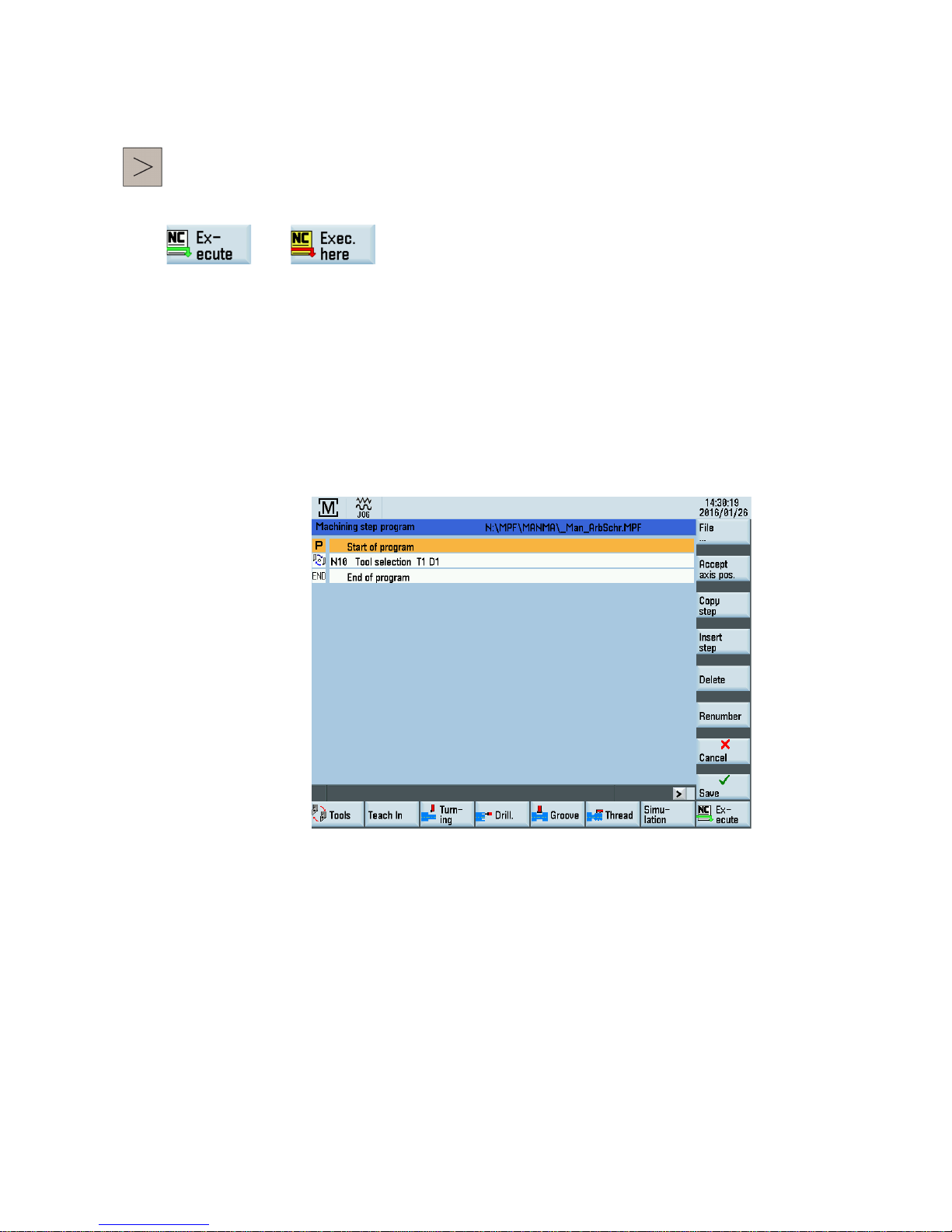
Programming and Operating Manual (Manual Machine Plus (MM+), Turning)
01/2017
73
This softkey opens the screen form in which the Executing the machining step program (Page 78) step program is actually
executed.
Changes the softkey function as follows.
From
to
5.1
Tool change in the machining step program
Functionality
You add a tool change step to the machining step program.
If the value of the display machine data 361 (USER_MEAS_TOOL_CHANGE) is 1, the tool number can be specified
manually; otherwise, the controller saves the active tool as machining step in the step program.
Operating sequences
1. You have opened a machining step progr
am.
Move the cursor to the machining step after which the tool should be changed.
Page 74
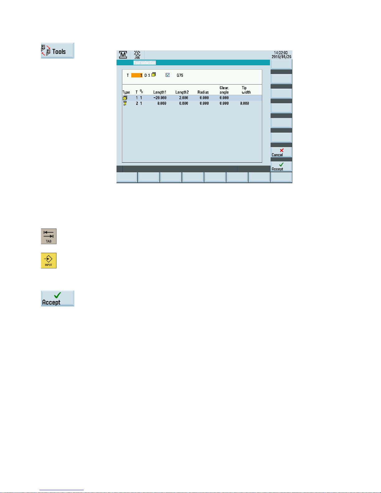
Programming and Operating Manual (Manual Machine Plus (MM+), Turning)
74 01/2017
2. Press this softkey and a list with all tools created in the control system will be displayed.
The fields "T" and "D" contain the active tool and the active cutting edge number, respe
c-
tively.
3.
To select the tool, enter the tool number and the cutting edge numb
er in the input fields "T"
and "D", respectively.
Alternatively, perform the following operations to select the tool:
Use this key to change to the list and position the cursor on the appropriate tool.
Then press this key to confirm the selection.
The selected tool is copied into the "T" input field.
4. If the t
ick is set in the field "G75" (approach fixed point), the controller travels to a stored
fixed point before the tool change.
5. Press this softkey.
Page 75
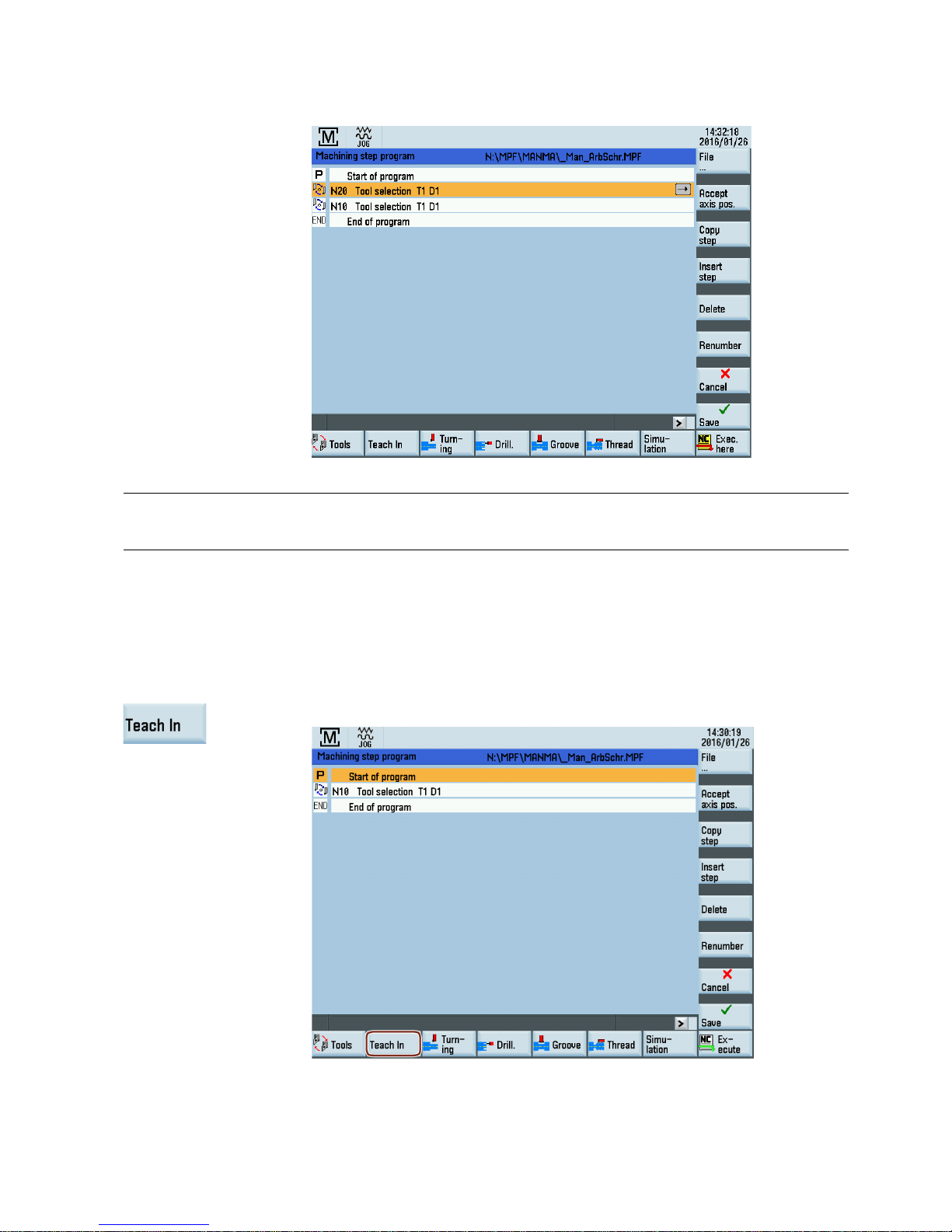
Programming and Operating Manual (Manual Machine Plus (MM+), Turning)
01/2017
75
6. The active tool is inserted into the step program as machining step.
Note
If the tool change is to be performed without travelling to a fixed point, travel to a safe machine position beforehand and save
this point as work step in the step program.
5.2
Teach In
Functionality
Using this function, an approached axis position can be directly entered into a specific traversing block.
Operating sequences
1. You can reach the teach in function in the machining step program by pressing this softkey.
Page 76
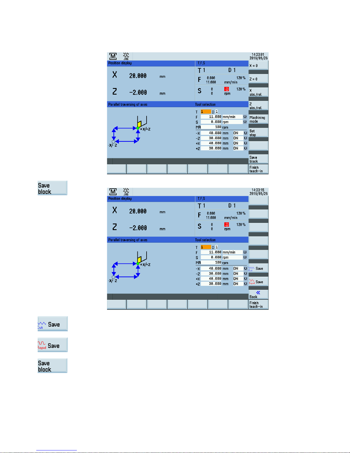
Programming and Operating Manual (Manual Machine Plus (MM+), Turning)
76 01/2017
The controller switches to the manual machining screen forms of axis
-parallel turning, taper
turning and radius turning.
2. Traverse to a position that is to be taught in and press this softkey.
3. You can save the position with path feed with this softkey.
4. You can save the position with rapid traverse via this softkey.
After the control acknowledged the action with a sc
reen message (for example, saying that
the block was inserted as N20), a new position could be traversed to and this is in turn
taught in using this softkey.
Page 77
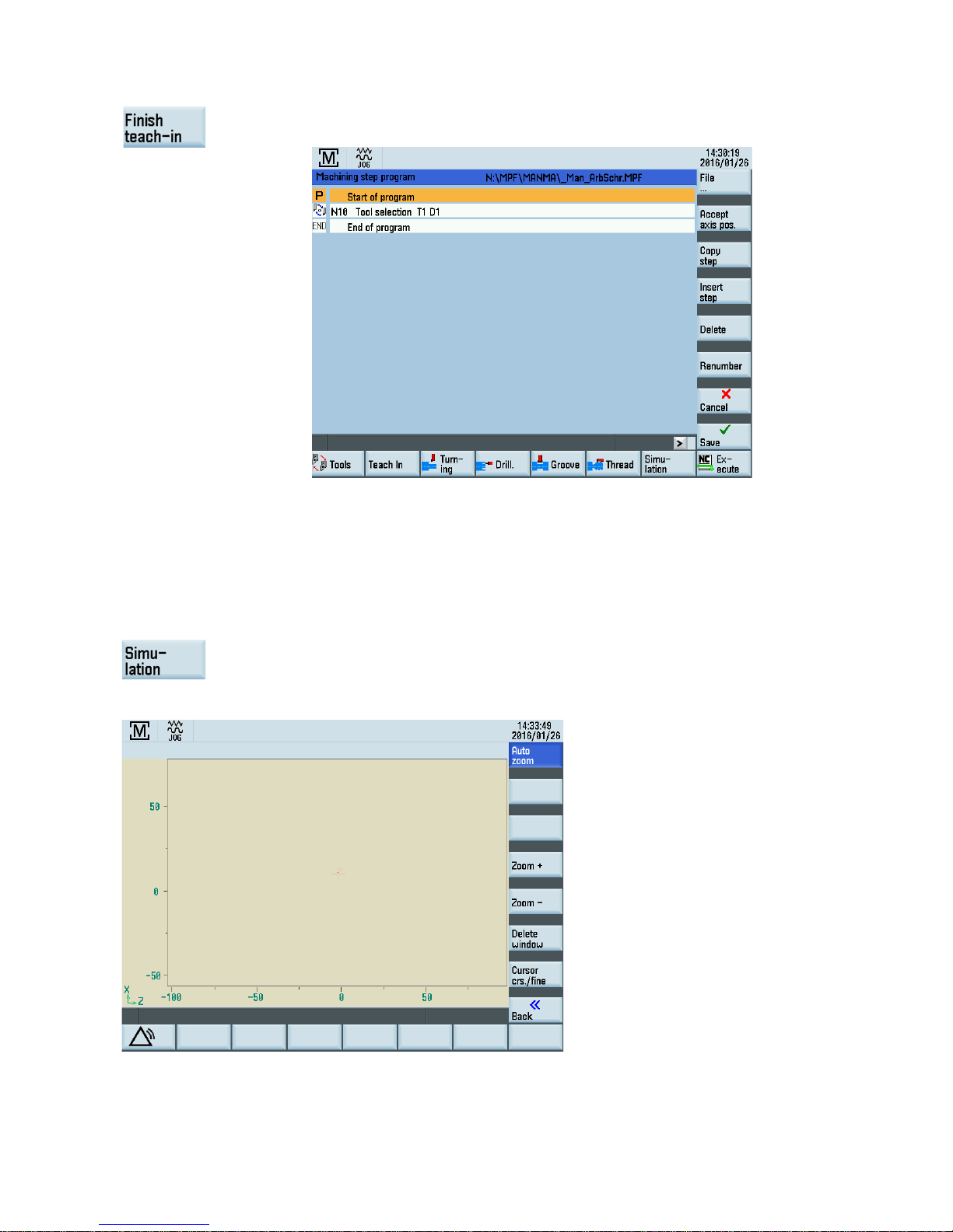
Programming and Operating Manual (Manual Machine Plus (MM+), Turning)
01/2017
77
5. Exit the teach in mode via this softkey.
The menu returns to the machining step program.
5.3
Simulate machining
Function
You can use this function to graphically display the execution of a single cycle on the screen.
Operating sequences
The start screen is opened.
Page 78
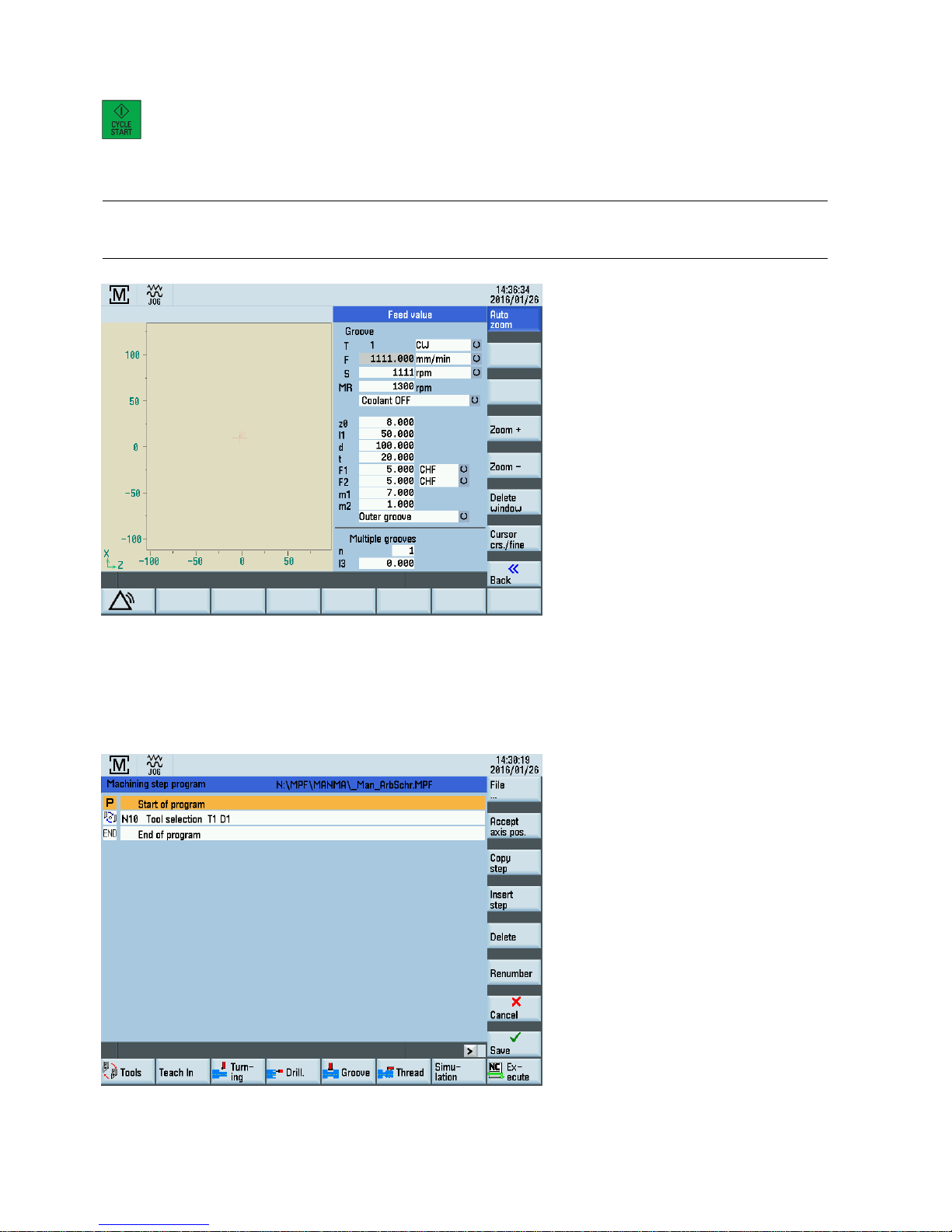
Programming and Operating Manual (Manual Machine Plus (MM+), Turning)
78 01/2017
Press the above hardkey to start the simulation for the selected part program.
Simulation of individual cycles
Note
If the simulation is used to test a single cycle, the display area is divided into the traversing movements and technology data
columns. The technology data cannot be changed in simulation mode.
References
For more information on further operating options for a simulation, see Chapter "Program simulation" of the SINUMERIK
808D/SINUMERIK 808D ADVANCED Programming and Operating Manual (Turning).
5.4
Executing the machining step program
Functionality
Page 79
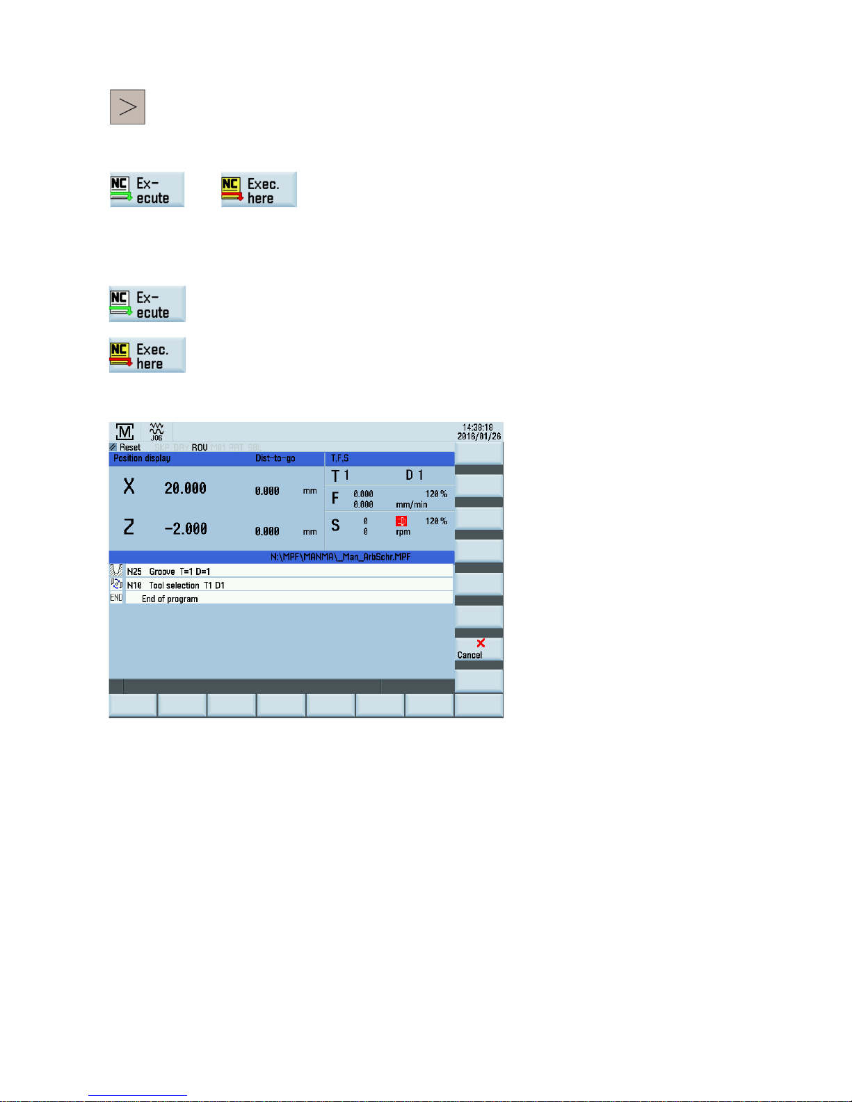
Programming and Operating Manual (Manual Machine Plus (MM+), Turning)
01/2017
79
In the "Machining step program" function, you can toggle between the following horizontal softkey functions using the above
hardkey.
and
The two functions change from the machining step program into that screen form in which the actual machining step
program is to be executed:
The complete machining step program is executed with the following:
With the above softkey, the program is executed from the actual cursor position in the machining step program (step that is
marked in the program).
Operating sequences, executing the machining step program
The current machining status is displayed in the center of the execute screen. This status could be one of the following:
● Machining not started
● Machining active
● Machining aborted
● Machining interrupted
● Machining finished
Page 80
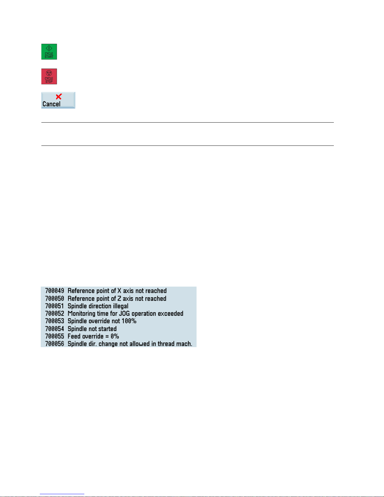
Programming and Operating Manual (Manual Machine Plus (MM+), Turning)
80 01/2017
1.
Start machining using this hardkey.
The machining operation on the workpiece is executed.
The individual machining steps are executed in the order in which you program them.
Press this hardkey
if you want to interrupt the machining operation.
2. If machining was terminated (for example, completed), the execution screen can be exited
using this softkey.
Note
The individual machining steps are performed with the currently programmed direction of spindle rotation. This need
not
coincide with the position of the spindle direction switch or with the spindle direction selected with the spindle keys.
6
Messages
Functionality
The meanings of the messages listed below differ from those given in the SINUMERIK 808D/SINUMERIK 808D
ADVANCED Diagnostics Manual:
10631
-X limit stop reached
10631
+X limit stop reached
10631
-Z limit stop reached
10631
+Z limit stop reached
PLC alarm messages are specially configured for the "Manual Machine Plus" system in the shipped version of the "Manual
Machine Plus" software.
The following list of PLC alarm messages applies, unless the machine manufacturer has defined an alternative or additional
list of errors.
Page 81

Programming and Operating Manual (Manual Machine Plus (MM+), Turning)
01/2017
Trademarks
All names identified by ® are registered trademarks of
Siemens AG
. The remaining trademarks in this publication may be trademarks whose
use by third parties for their own purposes could violate the rights of the owner.
Disclaimer of Liability
We have reviewed the contents of this publication to ensure consistency with
the hardware and software described. Since variance cannot
be precluded entirely, we cannot guarantee full consistency. However, the information in this publication is reviewed regular
ly and any
necessary corrections are included in subsequent editions.
Siemens AG
Division Digital Factory
Postfach 48 48
90026 NÜRNBERG
GERMANY
 Loading...