

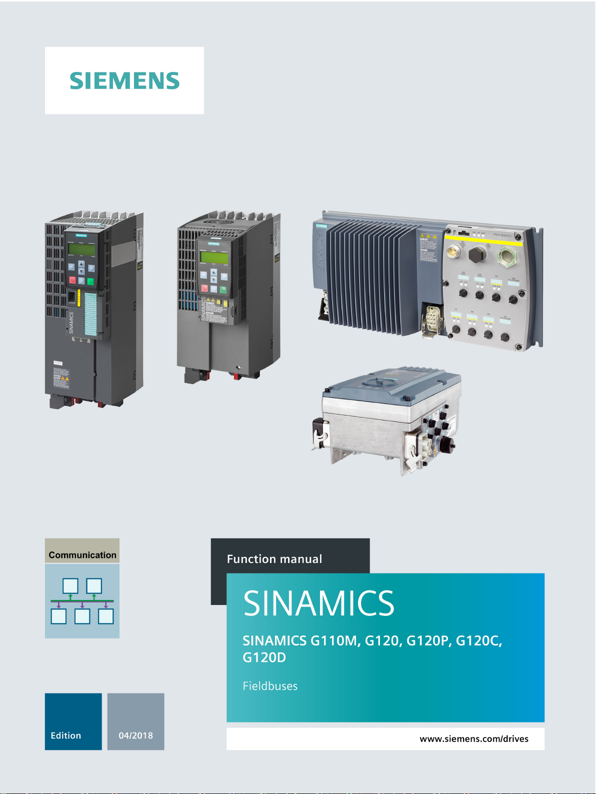
Siemens SINAMICS G110M, SINAMICS G120, SINAMICS G120P, SINAMICS G120C, SINAMICS G120D Function Manual
Page 1
Page 2

Page 3
___________________
___________________
___________________
___________________
___________________
___________________
___________________
___________________
___________________
SINAMICS
SINAMICS G120, G120P, G120C,
G120D, G110M
Fieldbuses
Function Manual
Edition 04/2018, firmware V4.7 SP10
04/2018, FW V4.7 SP10
A5E34229197B AE
Preface
Fundamental safety
instructions
1
General information
2
Communication via
PROFIBUS and PROFINET
3
Communication via
EtherNet/IP
4
Communication via RS485
5
Communication over
CANopen
6
Communication via AS-i only for G110M
7
Appendix
A
Page 4
Siemens AG
Division Digital Factory
Postfach 48 48
90026 NÜRNBERG
GERMANY
A5E34229197B AE
Ⓟ
Copyright © Siemens AG 2014 - 2018.
All rights reserved
Legal information
Warning notice system
DANGER
indicates that death or severe personal injury will result if proper precautions are not taken.
WARNING
indicates that death or severe personal injury may result if proper precautions are not taken.
CAUTION
indicates that minor personal injury can result if proper precautions are not taken.
NOTICE
indicates that property damage can result if proper precautions are not taken.
Qualified Personnel
personnel qualified
Proper use of Siemens products
WARNING
Siemens products may only be used for the applications described in the catalog and in the relevant technical
maintenance are required to ensure that the products operate safely and without any problems. The permissible
ambient conditions must be complied with. The information in the relevant documentation must be observed.
Trademarks
Disclaimer of Liability
This manual contains notices you have to observe in order to ensure your personal safety, as well as to prevent
damage to property. The notices referring to your personal safety are highlighted in the manual by a safety alert
symbol, notices referring only to property damage have no safety alert symbol. These notices shown below are
graded according to the degree of danger.
If more than one degree of danger is present, the warning notice representing the highest degree of danger will
be used. A notice warning of injury to persons with a safety alert symbol may also include a warning relating to
property damage.
The product/system described in this documentation may be operated only by
task in accordance with the relevant documentation, in particular its warning notices and safety instructions.
Qualified personnel are those who, based on their training and experience, are capable of identifying risks and
avoiding potential hazards when working with these products/systems.
Note the following:
documentation. If products and components from other manufacturers are used, these must be recommended
or approved by Siemens. Proper transport, storage, installation, assembly, commissioning, operation and
All names identified by ® are registered trademarks of Siemens AG. The remaining trademarks in this publication
may be trademarks whose use by third parties for their own purposes could violate the rights of the owner.
We have reviewed the contents of this publication to ensure consistency with the hardware and software
described. Since variance cannot be precluded entirely, we cannot guarantee full consistency. However, the
information in this publication is reviewed regularly and any necessary corrections are included in subsequent
editions.
for the specific
04/2018 Subject to change
Page 5

Preface
About this manual
Fieldbuses for SINAMICS G120
Additional fieldbuses for SINAMICS G120P
Additional fieldbuses for SINAMICS G110M
Changes in this edition
What is the meaning of the symbols in the manual?
This manual describes the settings and preconditions that are required to communicate with
a higher-level control system with the subsequently listed fieldbus systems.
● PROFIBUS DP
● PROFINET
● EtherNet/IP
● USS
● Modbus RTU
● CANopen
● BACnet MS/TP
● P1
● AS-Interface
Inverter settings are described in the context of the Startdrive PC commissioning tool. The
descriptions for settings using STARTER have been removed.
Reference to further information in the manual
Download from the Internet
DVD that can be ordered
End of a handling instruction.
❒
Fieldbuses
Function Manual, 04/2018, FW V4.7 SP10, A5E34229197B AE
3
Page 6

Preface
Fieldbuses
4 Function Manual, 04/2018, FW V4.7 SP10, A5E34229197B AE
Page 7

Table of contents
Preface ................................................................................................................................................... 3
1 Fundamental safety instructions .............................................................................................................. 9
2 General information .............................................................................................................................. 13
3 Communication via PROFIBUS and PROFINET ................................................................................... 17
1.1 General safety instructions ....................................................................................................... 9
1.2 Warranty and liability for application examples ........................................................................ 9
1.3 Industrial security .................................................................................................................... 10
2.1 Ethernet and PROFINET protocols that are used .................................................................. 14
3.1 PROFIDRIVE profile - Cyclic communication ......................................................................... 17
3.1.1 Assigning control and status words ........................................................................................ 21
3.1.1.1 Control and status word 1 ....................................................................................................... 21
3.1.1.2 Control and status word 2 ....................................................................................................... 25
3.1.1.3 Control and status word 3 ....................................................................................................... 26
3.1.2 NAMUR message word .......................................................................................................... 28
3.1.3 Control and status word, encoder ........................................................................................... 29
3.1.4 Position actual value of the encoder ....................................................................................... 31
3.1.5 Extend telegrams and change signal interconnection ............................................................ 33
3.1.6 Data structure of the parameter channel ................................................................................ 35
3.1.6.1 Application examples .............................................................................................................. 39
3.1.7 Slave-to-slave communication ................................................................................................ 41
3.2 PROFIDRIVE profile - Acyclic communication ....................................................................... 42
3.3 PROFIdrive profile - Diagnostic channels ............................................................................... 47
3.3.1 Diagnostics with PROFINET ................................................................................................... 48
3.3.2 Diagnostics with PROFIBUS .................................................................................................. 50
3.4 Identification & maintenance data (I&M) ................................................................................. 54
3.5 S7 communication .................................................................................................................. 55
3.5.1 Directly accessing a SINAMICS G120 converter from a SIMATIC panel ............................... 55
3.6 Communication via PROFINET .............................................................................................. 59
3.6.1 Converter with PROFINET interface ....................................................................................... 61
3.6.2 Integrating inverters into PROFINET ...................................................................................... 62
3.6.3 PROFINET IO operation ......................................................................................................... 63
3.6.3.1 What do you have to set for communication via PROFINET?................................................ 63
3.6.3.2 Configuring communication to the control .............................................................................. 63
3.6.3.3 Installing GSDML .................................................................................................................... 65
3.6.3.4 Activating diagnostics via the control ...................................................................................... 65
3.6.4 PROFIenergy .......................................................................................................................... 65
3.6.4.1 General inverter behavior when in the PROFIenergy energy-saving mode ........................... 66
3.6.4.2 Supported PROFIenergy energy-saving modes ..................................................................... 66
3.6.4.3 Settings and displays for PROFIenergy in the inverter ........................................................... 67
3.6.4.4 Control commands and status queries ................................................................................... 68
Fieldbuses
Function Manual, 04/2018, FW V4.7 SP10, A5E34229197B AE
5
Page 8

Table of contents
4 Communication via EtherNet/IP ............................................................................................................ 81
5 Communication via RS485 ................................................................................................................... 107
3.6.5 The inverter with PROFINET interface as Ethernet node. ..................................................... 70
3.7 Communication via PROFIBUS ............................................................................................. 72
3.7.1 Inverters with PROFIBUS interface ....................................................................................... 73
3.7.2 What do you have to set for communication via PROFIBUS? .............................................. 75
3.7.3 Integrating inverters into PROFIBUS ..................................................................................... 76
3.7.4 Configuring communication to the control system ................................................................. 76
3.7.4.1 Configuring the communication using SIMATIC S7 control ................................................... 76
3.7.4.2 Configuring the communication with a third-party control system ......................................... 76
3.7.4.3 Installing the GSD .................................................................................................................. 77
3.7.5 Setting the address ................................................................................................................ 78
3.8 Select telegram ...................................................................................................................... 79
4.1 Inverters with Ethernet/IP interface ........................................................................................ 82
4.2 Connect converter to Ethernet/IP........................................................................................... 84
4.3 What do you need for communication via Ethernet/IP?......................................................... 85
4.4 Configuring communication via EtherNet/IP .......................................................................... 86
4.4.1 Communication settings ......................................................................................................... 86
4.4.2 Special issues if you wish to use the ODVA AC/DC Drive profile ......................................... 87
4.5 Supported objects .................................................................................................................. 88
4.5.1 Supported ODVA AC/DC assemblies .................................................................................. 102
4.6 Create generic I/O module ................................................................................................... 103
4.7 The inverter as an Ethernet station ...................................................................................... 104
5.1 Inverter with RS485 interface ............................................................................................... 108
5.2 Integrating inverters into a bus system via the RS485 interface ......................................... 110
5.3 Communication via USS ...................................................................................................... 111
5.3.1 Basic settings for communication ........................................................................................ 111
5.3.1.1 Setting the address .............................................................................................................. 112
5.3.1.2 Parameters to set communication via USS ......................................................................... 113
5.3.2 Telegram structure ............................................................................................................... 114
5.3.3 User data range of the USS telegram .................................................................................. 115
5.3.4 USS parameter channel ....................................................................................................... 116
5.3.4.1 Telegram examples, length of the parameter channel = 4 .................................................. 120
5.3.5 USS process data channel (PZD) ........................................................................................ 122
5.3.6 Time-out and other errors .................................................................................................... 123
5.4 Communication using Modbus RTU .................................................................................... 125
5.4.1 Basic settings for communication ........................................................................................ 126
5.4.1.1 Setting the address .............................................................................................................. 127
5.4.1.2 Parameters for Modbus communication settings ................................................................. 128
5.4.2 Modbus RTU telegram ......................................................................................................... 130
5.4.3 Baud rates and mapping tables ........................................................................................... 131
5.4.4 Mapping tables - inverter data ............................................................................................. 133
5.4.5 Acyclic communication via Modbus RTU ............................................................................. 136
5.4.6 Write and read access using function codes ....................................................................... 137
5.4.7 Acyclically read and write parameter via FC 16 ................................................................... 140
Fieldbuses
6 Function Manual, 04/2018, FW V4.7 SP10, A5E34229197B AE
Page 9

Table of contents
6 Communication over CANopen ........................................................................................................... 169
7 Communication via AS-i - only for G110M ........................................................................................... 215
5.4.7.1 Read parameter .................................................................................................................... 141
5.4.7.2 Write parameter .................................................................................................................... 142
5.4.8 Communication procedure .................................................................................................... 144
5.4.9 Application example .............................................................................................................. 145
5.5 Communication via BACnet MS/TP - only CU230P-2 HVAC / BT ....................................... 146
5.5.1 Basic settings for communication ......................................................................................... 147
5.5.1.1 Setting the address ............................................................................................................... 148
5.5.1.2 Parameters for setting communication via BACnet .............................................................. 149
5.5.2 Supported services and objects ............................................................................................ 151
5.5.3 Acyclic communication (general parameter access) via BACnet ......................................... 160
5.6 Communication via P1 - only CU230P-2 HVAC, CU230P-2 BT........................................... 162
5.6.1 Basic settings for communication via P1 .............................................................................. 163
5.6.2 Setting the address ............................................................................................................... 164
5.6.3 Point numbers ....................................................................................................................... 165
6.1 Network management (NMT service) ................................................................................... 172
6.2 SDO services ........................................................................................................................ 175
6.2.1 Access to SINAMICS parameters via SDO .......................................................................... 175
6.2.2 Access PZD objects via SDO ............................................................................................... 177
6.3 PDO services ........................................................................................................................ 179
6.3.1 Predefined connection set .................................................................................................... 182
6.3.2 Free PDO mapping ............................................................................................................... 184
6.3.3 Interconnect objects from the receive and transmit buffers .................................................. 187
6.3.4 Free PDO mapping for example of the actual current value and torque limit....................... 189
6.4 CANopen operating modes .................................................................................................. 191
6.5 RAM to ROM via the CANopen object 1010 ........................................................................ 193
6.6 Object directories .................................................................................................................. 194
6.6.1 General objects from the CiA 301 communication profile .................................................... 194
6.6.2 Free objects .......................................................................................................................... 203
6.6.3 Objects from the CiA 402 drive profile .................................................................................. 204
6.7 Integrating the inverter into CANopen .................................................................................. 206
6.7.1 Connecting inverter to CAN bus ........................................................................................... 207
6.7.2 Setting the node ID and baud rate ........................................................................................ 207
6.7.3 Setting the monitoring of the communication ....................................................................... 208
6.8 Error diagnostics ................................................................................................................... 210
6.9 CAN bus sampling time ........................................................................................................ 214
7.1 Setting the address ............................................................................................................... 217
7.2 Single Slave mode ................................................................................................................ 219
7.3 Dual Slave mode ................................................................................................................... 221
7.4 Assignment tables ................................................................................................................. 224
7.5 Cyclic and acyclic communication via CTT2 ........................................................................ 226
7.5.1 Cyclic communication ........................................................................................................... 227
Fieldbuses
Function Manual, 04/2018, FW V4.7 SP10, A5E34229197B AE
7
Page 10

Table of contents
A Appendix ............................................................................................................................................. 231
Index ................................................................................................................................................... 239
7.5.2 Acyclic communication - standard ....................................................................................... 228
7.5.3 Acyclic communication - manufacturer-specific ................................................................... 228
A.1 Application examples for communication with STEP7......................................................... 231
A.2 Manuals and technical support ............................................................................................ 232
A.2.1 Overview of the manuals ..................................................................................................... 232
A.2.2 Configuring support .............................................................................................................. 236
A.2.3 Product Support ................................................................................................................... 237
Fieldbuses
8 Function Manual, 04/2018, FW V4.7 SP10, A5E34229197B AE
Page 11
1
1.1
General safety instructions
WARNING
Danger to life if the safety instructions and residual risks are not observed
WARNING
Malfunctions of the machine as a result of incorrect or changed parameter settings
1.2
Warranty and liability for application examples
If the safety instructions and residual risks in the associated hardware documentation are
not observed, accidents involving severe injuries or death can occur.
• Observe the safety instructions given in the hardware documentation.
• Consider the residual risks for the risk evaluation.
As a result of incorrect or changed parameterization, machines can malfunction, which in
turn can lead to injuries or death.
• Protect the parameterization (parameter assignments) against unauthorized access.
• Handle possible malfunctions by taking suitable measures, e.g. emergency stop or
emergency off.
Application examples are not binding and do not claim to be complete regarding
configuration, equipment or any eventuality which may arise. Application examples do not
represent specific customer solutions, but are only intended to provide support for typical
tasks.
As the user you yourself are responsible for ensuring that the products described are
operated correctly. Application examples do not relieve you of your responsibility for safe
handling when using, installing, operating and maintaining the equipment.
Fieldbuses
Function Manual, 04/2018, FW V4.7 SP10, A5E34229197B AE
9
Page 12

Fundamental safety instructions
1.3
Industrial security
Note
Industrial security
Siemens provides products and solutions with industrial security functions that support the
secure operation of plants, systems, machines and networks.
In order to protect plants, systems, machines and networks against cyber threats, it is
necessary to implement
security concept. Siemens’ products and solutions constitute one element of
Customers are responsible for preventing unauthorized access to their plants, systems,
machines and networks. Such systems, machines and components should only be
connected to an enterprise network or the Internet if and to the extent such
necessary and only when appropriate security measures (e.g. firewalls and/or network
segmentation) are in place.
For additional information on industrial security measures that may be implemented, please
visit:
Industrial security (
Siemens’ products and solutions undergo continuous development to make them more
secure. Siemens strongly recommends that product updates are applied as soon as they are
available and that the latest product versions are used. Use of product versions that are no
longer supported, and failure to apply the latest updates may increase customer’s exposure
to cyber threats.
To stay informed about product updates, subs
Feed at:
Industrial security (
1.3 Industrial security
– and continuously maintain – a holistic, state-of-the-art industrial
such a concept.
a connection is
http://www.siemens.com/industrialsecurity)
cribe to the Siemens Industrial Security RSS
http://www.siemens.com/industrialsecurity)
Further information is provided on the Internet:
Industrial Security Configuration Manual
(https://support.industry.siemens.com/cs/ww/en/view/108862708)
Fieldbuses
10 Function Manual, 04/2018, FW V4.7 SP10, A5E34229197B AE
Page 13

Fundamental safety instructions
WARNING
Unsafe operating states resulting from software manipulation
1.3 Industrial security
Software manipulations (e.g. viruses, trojans, malware or worms) can cause unsafe
operating states in your system that may lead to death, serious injury, and property
damage.
• Keep the software up to date.
• Incorporate the automation and drive components into a holistic, state-of-the-art
industrial security concept for the installation or machine.
• Make sure that you include all installed products into the holistic industrial security
concept.
• Protect files stored on exchangeable storage media from malicious software by with
suitable protection measures, e.g. virus scanners.
• Protect the drive against unauthorized changes by activating the "know-how protection"
drive function.
Fieldbuses
Function Manual, 04/2018, FW V4.7 SP10, A5E34229197B AE
11
Page 14

Fundamental safety instructions
1.3 Industrial security
Fieldbuses
12 Function Manual, 04/2018, FW V4.7 SP10, A5E34229197B AE
Page 15

2
Communication with the control, even when the line voltage is switched off
If, in your plant or system, communication with the control system should continue to function
even when the line voltage is switched off, then you must externally supply the
inverter/Control Unit with 24 V DC. To do this, use terminals 31 and 32 – or connector X01.
You can find additional details in the operating instructions for the inverter or the Control
Unit.
Fieldbuses
Function Manual, 04/2018, FW V4.7 SP10, A5E34229197B AE
13
Page 16

General information
2.1
Ethernet and PROFINET protocols that are used
Protocol
Port
number
Layer
(2) Link layer
(4) Transport layer
Function/description
Accessible stations, PROFINET Discovery and configuration
xx-xx-xx = Organizationally Unique Identifier
PROFINET Link Layer Discovery protocol
01-80-C2-00-00-0E
PROFINET medium redundancy
xx-xx-xx = Organizationally Unique Identifier
PROFINET send clock and time synchronization, based on IEEE
1588
xx-xx-xx = Organizationally Unique Identifier
(PROFINET)
PROFINET Cyclic IO data transfer
PROFINET connection less RPC
order to establish an application relationship (PROFINET AR).
2.1 Ethernet and PROFINET protocols that are used
The inverter supports the protocols listed in the following tables. The address parameters,
the relevant communication layer as well as the communication role and the communication
direction are specified for each protocol.
You require this information to set the appropriate safety measures to protect the automation
system, e.g. in the firewall.
As the security measures are limited to Ethernet and PROFINET networks, no PROFIBUS
protocols are listed in the table.
Table 2- 1 PROFINET protocols
DCP:
Discovery and
configuration
protocol
LLDP:
Link Layer
Discovery
Protocol
MRP:
Media Redun-
dancy Protocol
PTCP
Precision
Transparent
Clock Protocol
Not
relevant
Not
relevant
Not
relevant
Not
relevant
(2) Ethernet II and
IEEE 802.1Q and
Ethertype 0x8892
(PROFINET)
(2) Ethernet II and
IEEE 802.1Q and
Ethertype 0x88CC
(PROFINET)
(2) Ethernet II and
IEEE 802.1Q and
Ethertype 0x88E3
(PROFINET)
(2) Ethernet II and
IEEE 802.1Q and
Ethertype 0x8892
(PROFINET)
DCP is used by PROFINET to determine PROFINET devices and to
make basic settings.
DCP uses the special multicast MAC address:
xx-xx-xx-01-0E-CF,
LLDP is used by PROFINET to determine and manage neighborhood relationships between PROFINET devices.
LLDP uses the special multicast MAC address:
MRP enables the control of redundant routes through a ring topology.
MRP uses the special multicast MAC address:
xx-xx-xx-01-15-4E,
PTC is used to implement send clock synchronization and time synchronization between RJ45 ports, which are required for IRT operation.
PTCP uses the special multicast MAC address:
xx-xx-xx-01-0E-CF,
PROFINET IO
data
PROFINET
Context Manager
Fieldbuses
14 Function Manual, 04/2018, FW V4.7 SP10, A5E34229197B AE
Not
relevant
34964 (4) UDP
(2) Ethernet II and
IEEE 802.1Q and
Ethertype 0x8892
The PROFINET IO telegrams are used to transfer IO data cyclically
between the PROFINET IO controller and IO devices via Ethernet.
The PROFINET context manager provides an endpoint mapper in
Page 17

General information
Protocol
Port
number
Layer
(2) Link layer
(4) Transport layer
Function/description
Net/IP.
Net/IP.
Protocol
Port
number
Layer
(2) Link layer
(4) Transport layer
Function/description
ISO-on-TCP protocol
oriented data exchange to a remote CPU, WinAC or devices of other
and is always required.
Simple network management protocol
It is activated in the factory setting, and is always required
(4) UDP
2.1 Ethernet and PROFINET protocols that are used
Table 2- 2 Ethernet/IP protocols
Implicit messaging
Explicit messaging
2222 (4) UDP Used for exchanging I/O data.
This is inactive when delivered. Is activated when selecting Ether-
44818 (4) TCP
(4) UDP
Used for parameter access (writing, reading).
This is inactive when delivered. Is activated when selecting Ether-
Table 2- 3 Connection-oriented communication protocols
ISO on TCP
(according to
RFC 1006)
102 (4) TCP
ISO on TCP (according to RFC 1006) is used for the message-
suppliers.
Communication with ES, HMI, etc. is activated in the factory setting,
SNMP
Simple Net-
work Manage-
161 (4) UDP
SNMP enables network management data to be read out and set
(SNMP managed objects) by the SNMP manager.
ment Protocol
Reserved 49152 ...
(4) TCP
65535
Fieldbuses
Function Manual, 04/2018, FW V4.7 SP10, A5E34229197B AE
Dynamic port area that is used for the active connection endpoint if
the application does not specify the local port.
15
Page 18

General information
2.1 Ethernet and PROFINET protocols that are used
Fieldbuses
16 Function Manual, 04/2018, FW V4.7 SP10, A5E34229197B AE
Page 19
3
3.1
PROFIDRIVE profile - Cyclic communication
Communication telegrams if "basic positioner" has been configured
Communication telegrams for speed control
Depending on the Control Unit or inverter, there are different telegrams for communication
via PROFIBUS DP or PROFINET IO. The structure of the individual telegrams are listed
below.
The Startdrive commissioning tool or an operator panel only list the telegrams for selection
that are possible with your particular inverter.
How to commission the inverter and select a telegram are described in the operating
instructions.
Overview of the manuals (Page 232)
The inverter has the following telegrams if you have configured the "Basic positioner"
function:
● Standard telegram 7, PZD-2/2
● Standard telegram 9, PZD-10/5
● SIEMENS telegram 110, PZD-12/7
● SIEMENS telegram 111, PZD-12/12
● Telegram 999, free interconnection
Telegrams 7, 9, 110 and 111 are described in the "Basic positioner" Function Manual
Overview of the manuals (Page 232)
The send and receive telegrams of the inverter for closed-loop speed control are structured
as follows:
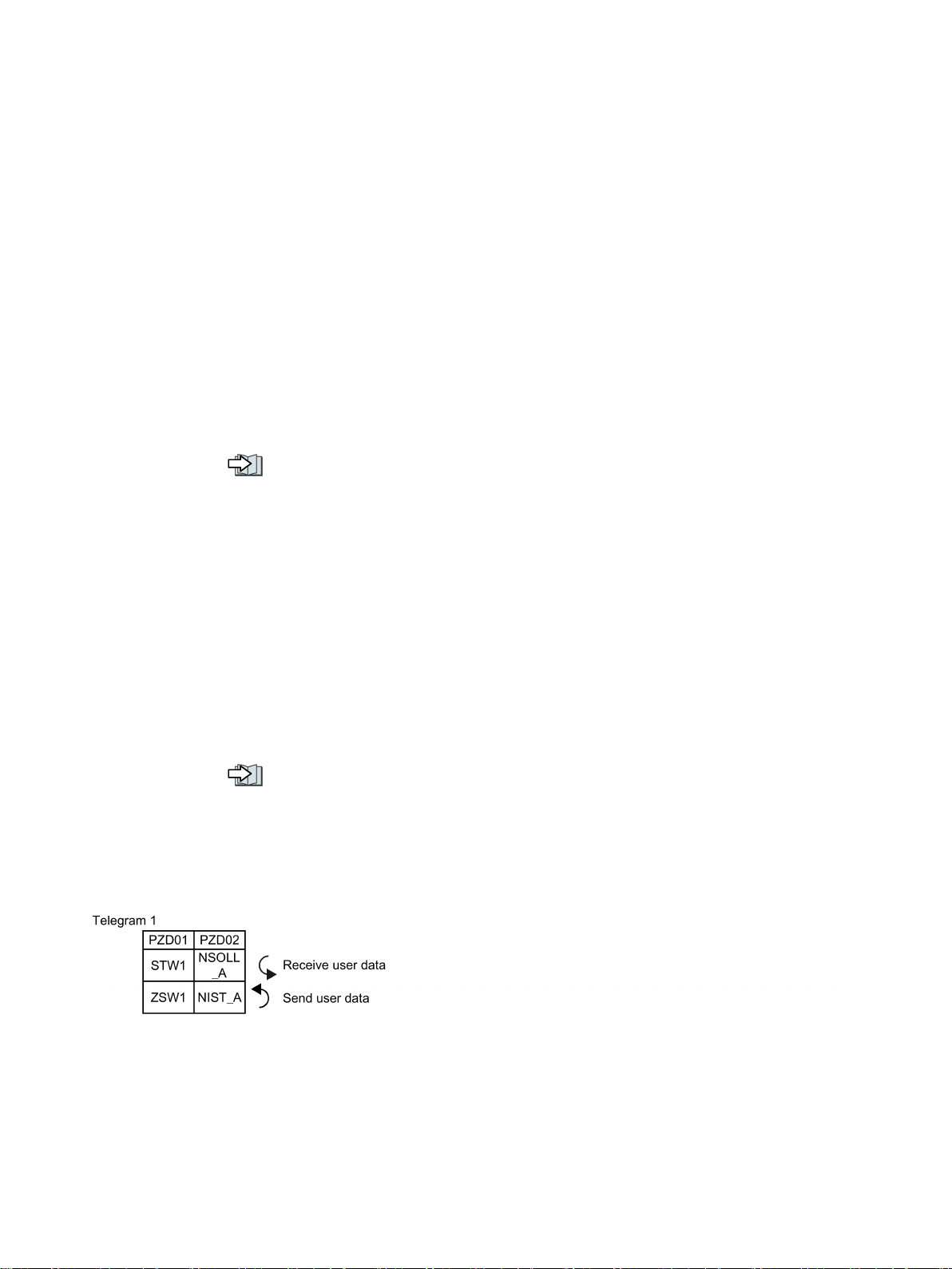
Figure 3-1 16-bit speed setpoint
Fieldbuses
Function Manual, 04/2018, FW V4.7 SP10, A5E34229197B AE
17
Page 20
Communication via PROFIBUS and PROFINET
3.1 PROFIDRIVE profile - Cyclic communication
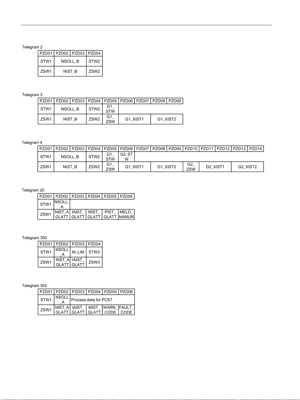
Figure 3-2 32-bit speed setpoint
Figure 3-3 32-bit speed setpoint with 1 position encoder
Figure 3-4 32-bit speed setpoint with 2 position encoders
Figure 3-5 16-bit speed setpoint for VIK-Namur
Figure 3-6 16-bit speed setpoint with torque limiting
Figure 3-7 16-bit speed setpoint for PCS7
Fieldbuses
18 Function Manual, 04/2018, FW V4.7 SP10, A5E34229197B AE
Page 21
Communication via PROFIBUS and PROFINET
Abbreviation
Explanation
Abbreviation
Explanation
PZD
Process data
PKW
Parameter channel
STW
Control word
PIST_GLATT
Actual active power value, smoothed
ZSW
Status word
M_LIM
Torque limit
definition
G2_STW
G2_ZSW
G2_XIST1
encoder 2
G2_XIST2
encoder 2
3.1 PROFIDRIVE profile - Cyclic communication
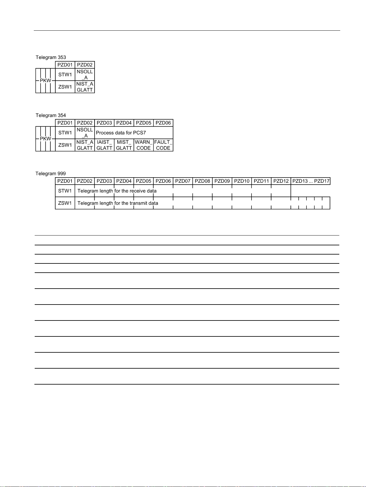
Figure 3-8 16-bit speed setpoint with PKW range to read and write parameters
Figure 3-9 16-bit speed setpoint for PCS7 with PKW range to read and write parameters
Figure 3-10 Telegram with free interconnection and length
NSOLL_A Speed setpoint 16 bit FAULT_CODE Fault code
NSOLL_B Speed setpoint 32 bit WARN_CODE Alarm code
NIST_A Speed actual value 16 bit MELD_NAMUR Message according to the VIK-NAMUR
NIST_B Speed actual value 32 bit G1_STW /
IAIST Current actual value G1_ZSW /
IAIST_GLATT Current actual value, smoothed G1_XIST1 /
MIST_GLATT Torque actual value, smoothed G1_XIST2 /
Control word for encoder 1 or encoder 2
Status word for encoder 1 or encoder 2
Position actual value 1 from encoder 1 or
Position actual value 2 from encoder 1 or
Fieldbuses
Function Manual, 04/2018, FW V4.7 SP10, A5E34229197B AE
19
Page 22
Communication via PROFIBUS and PROFINET
Interconnection of the process data
3.1 PROFIDRIVE profile - Cyclic communication
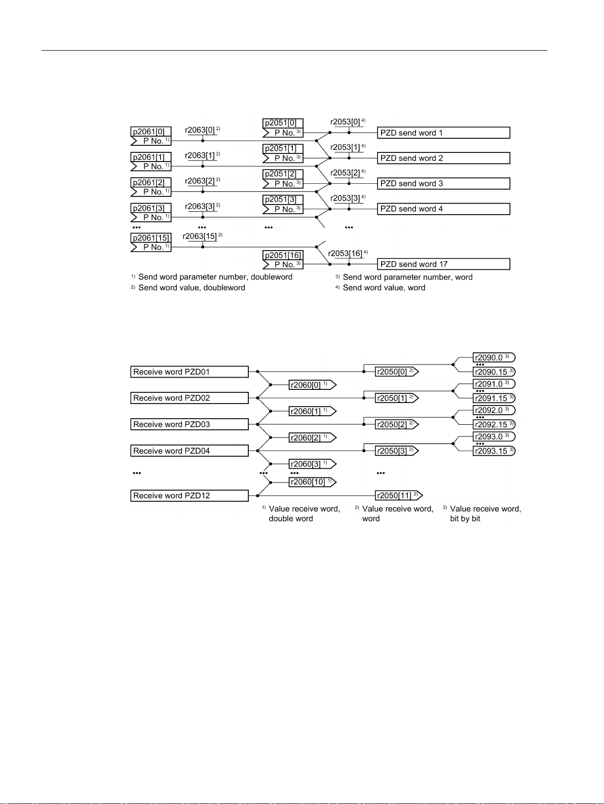
Figure 3-11 Interconnection of the send words
Figure 3-12 Interconnection of the receive words
The telegrams use - with the exception of telegram 999 (free interconnection) - the word-byword transfer of send and receive data (r2050/p2051).
If you require an individual telegram for your application (e.g. for transferring double words),
you can adapt one of the predefined telegrams using parameters p0922 and p2079. For
details, please refer to the List Manual, function diagrams 2420 and 2472.
Fieldbuses
20 Function Manual, 04/2018, FW V4.7 SP10, A5E34229197B AE
Page 23

Communication via PROFIBUS and PROFINET
3.1.1
Assigning control and status words
3.1.1.1
Control and status word 1
3.1 PROFIDRIVE profile - Cyclic communication
Assigning control and status of words is specified in part by the definitions in the PROFIdrive
profile, Version 4.2 for the "Closed-loop speed control" operating mode; the other part is
assigned depending on the particular manufacturer.
A more detailed description of the individual control and status words is provided in the
following sections.
If you require an individual assignment for your application, you can adapt one of the existing
control and status words using p0922 and p2079.
Extend telegrams and change signal interconnection (Page 33)
Control word 1 is preassigned as follows:
● Telegrams 1, 2, 3 and 4:
– Bits 0 … 10 corresponding to the PROFIdrive profile,
– Bits 11… 15 manufacturer-specific
● Telegrams 7 and 9:
– Bits 0 … 11 corresponding to the PROFIdrive profile,
– Bits 12 … 15 manufacturer-specific
● Telegram 20 (VIK/NAMUR):
– Bits 0 … 11 corresponding to the PROFIdrive profile
– Bits 12 … 14 reserved
– Bit 15 corresponding to the PROFIdrive profile
Status word 1 is preassigned as follows:
● Telegrams 1, 2, 3 and 4:
– Bits 0 … 10 corresponding to the PROFIdrive profile,
– Bits 11… 15 manufacturer-specific
● Telegrams 7 and 9:
– Bits 0 … 13 corresponding to the PROFIdrive profile,
– Bits 14 … 15 manufacturer-specific
● Telegram 20 (VIK/NAMUR):
– Bits 0 … 11 corresponding to the PROFIdrive profile
– Bit 12 reserved
– Bits 13 … 15 corresponding to the PROFIdrive profile
Fieldbuses
Function Manual, 04/2018, FW V4.7 SP10, A5E34229197B AE
21
Page 24
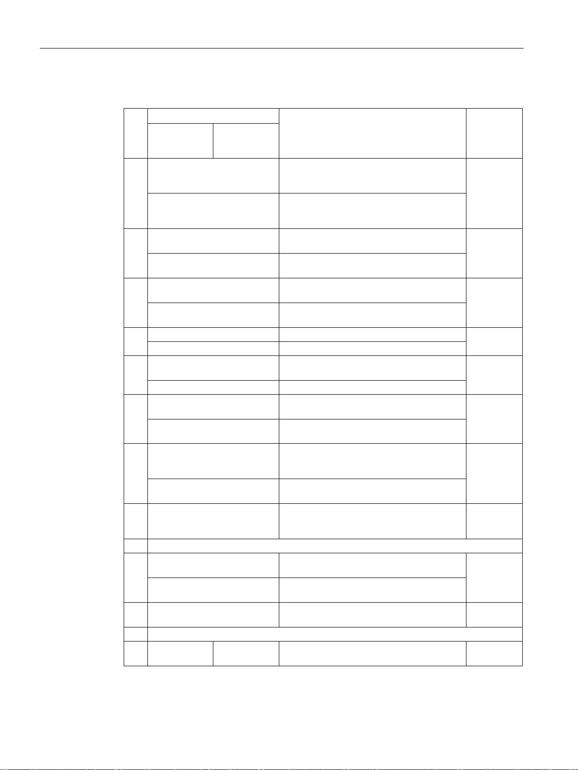
Communication via PROFIBUS and PROFINET
Control word 1 (STW1)
Bit
Significance
Explanation
Signal interconnection
in the inverter
Telegram 20
All other telegrams
inverter switches off the motor at standstill.
1, then the inverter switches on
the motor.
then coasts down to a standstill.
mand).
ramp-down time p1135 down to standstill.
mand).
0 = Inhibit operation
Immediately switch-off motor (cancel pulses).
1 = Enable operation
Switch-on motor (pulses can be enabled).
function generator output to 0.
1 = Do not disable RFG
The ramp-function generator can be enabled.
stops at the actual value.
follows the setpoint.
p1120 to the setpoint.
on inhibited" state.
8, 9
Reserved
fieldbus.
cess data from the fieldbus.
r2090.11
12
Not used
potentiometer.
r2090.13
3.1 PROFIDRIVE profile - Cyclic communication
0 0 = OFF1 The motor brakes with the ramp-down time
p1121 of the ramp-function generator. The
0 → 1 = ON The inverter goes into the "ready" state. If, in
addition bit 3 =
1 0 = OFF2 Switch off the motor immediately, the motor
1 = No OFF2 The motor can be switched on (ON com-
2 0 = Quick stop (OFF3) Quick stop: The motor brakes with the OFF3
1 = No quick stop (OFF3) The motor can be switched on (ON com-
3
4 0 = Disable RFG The inverter immediately sets its ramp-
5 0 = Stop RFG The output of the ramp-function generator
1 = Enable RFG The output of the ramp-function generator
p0840[0] =
r2090.0
p0844[0] =
r2090.1
p0848[0] =
r2090.2
p0852[0] =
r2090.3
p1140[0] =
r2090.4
p1141[0] =
r2090.5
6 0 = Inhibit setpoint The inverter brakes the motor with the ramp-
1 = Enable setpoint Motor accelerates with the ramp-up time
7 0 → 1 = Acknowledge faults Acknowledge fault. If the ON command is still
10 0 = No control via PLC Inverter ignores the process data from the
1 = Control via PLC Control via fieldbus, inverter accepts the pro-
11 1 = Direction reversal Invert setpoint in the inverter. p1113[0] =
13 ---1) 1 = MOP up Increase the setpoint saved in the motorized
Fieldbuses
22 Function Manual, 04/2018, FW V4.7 SP10, A5E34229197B AE
down time p1121 of the ramp-function generator.
active, the inverter switches to the "switching
p1142[0] =
r2090.6
p2103[0] =
r2090.7
p0854[0] =
r2090.10
p1035[0] =
Page 25
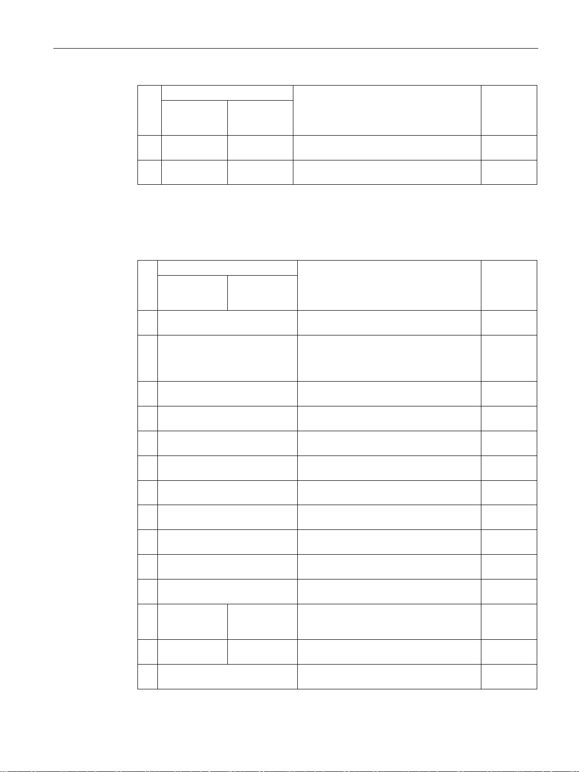
Communication via PROFIBUS and PROFINET
Bit
Significance
Explanation
Signal interconnection
in the inverter
Telegram 20
All other telegrams
potentiometer.
r2090.14
1)
telegram is kept.
Status word 1 (ZSW1)
Bit
Significance
Remarks
Signal interconnection
in the inverter
Telegram 20
All other telegrams
ized; pulses locked.
r0899.0
motor.
bit 3.
r0899.2
using STW1.7.
r2139.3
r0899.4
r0899.5
an OFF1 followed by ON.
r0899.6
edgement is necessary.
r2139.7
tolerance range
tolerance range.
r2197.7
cept the inverter control.
r0899.9
1 = Comparison speed reached or
exceeded
sponding maximum speed.
r2199.1
reached
r1407.7
brake open
brake.
r0899.12
r2135.14
3.1 PROFIDRIVE profile - Cyclic communication
14 ---1) 1 = MOP down Reduce the setpoint saved in the motorized
15 CDS bit 0 Reserved Changes over between settings for different
If you change over from another telegram to telegram 20, then the assignment of the previous
0 1 = Ready for switching on Power supply switched on; electronics initial-
1 1 = Ready Motor is switched on (ON/OFF1 = 1), no fault
2 1 = Operation enabled Motor follows setpoint. See control word 1,
3 1 = Fault active The inverter has a fault. Acknowledge fault
operation interfaces (command data sets).
is active. With the command "Enable operation" (STW1.3), the inverter switches on the
p1036[0] =
p0810 =
r2090.15
p2080[0] =
p2080[1] =
r0899.1
p2080[2] =
p2080[3] =
4 1 = OFF2 inactive Coast down to standstill is not active. p2080[4] =
5 1 = OFF3 inactive Quick stop is not active. p2080[5] =
6 1 = Switching on inhibited active It is only possible to switch on the motor after
7 1 = Alarm active Motor remains switched on; no acknowl-
8 1 = Speed deviation within the
9 1 = Master control requested The automation system is requested to ac-
10
11 1 = current or
torque limit
12 ---1) 1 = Holding
13 0 = Alarm, motor overtemperature -- p2080[13] =
1 = torque limit
reached
Setpoint / actual value deviation within the
Speed is greater than or equal to the corre-
Comparison value for current or torque has
been reached or exceeded.
Signal to open and close a motor holding
p2080[6] =
p2080[7] =
p2080[8] =
p2080[9] =
p2080[10] =
p2080[11] =
r0056.13 /
p2080[12] =
Fieldbuses
Function Manual, 04/2018, FW V4.7 SP10, A5E34229197B AE
23
Page 26
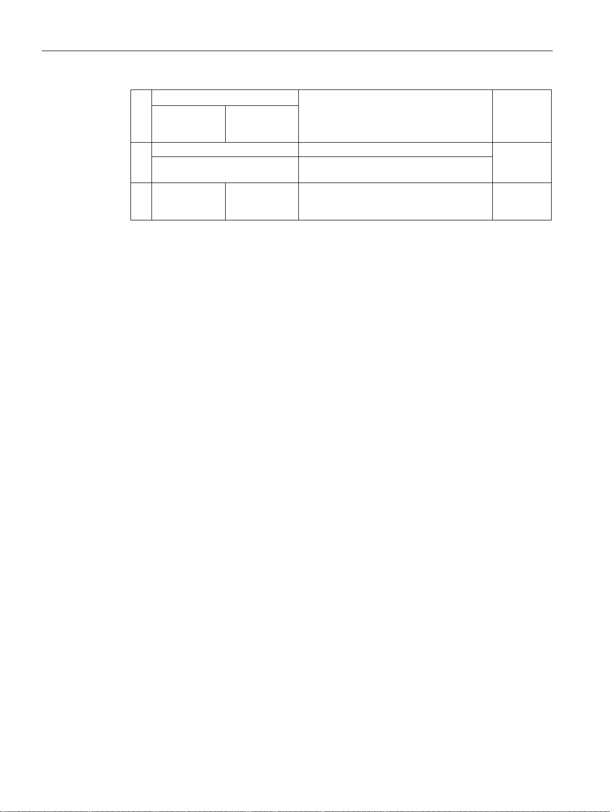
Communication via PROFIBUS and PROFINET
Bit
Significance
Remarks
Signal interconnection
in the inverter
Telegram 20
All other telegrams
1 = Motor rotates clockwise
Internal inverter actual value > 0
overload
r2135.15
1)
telegram is kept.
3.1 PROFIDRIVE profile - Cyclic communication
14
0 = Motor rotates counter-
Internal inverter actual value < 0
p2080[14] =
r2197.3
clockwise
15 1 = CDS display 0 = Alarm, in-
verter thermal
p2080[15] =
r0836.0 /
If you change over from another telegram to telegram 20, then the assignment of the previous
Fieldbuses
24 Function Manual, 04/2018, FW V4.7 SP10, A5E34229197B AE
Page 27
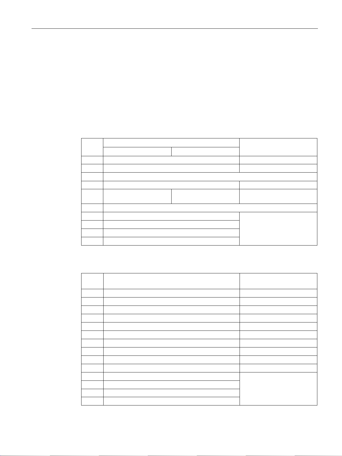
Communication via PROFIBUS and PROFINET
3.1.1.2
Control and status word 2
Control word 2 (STW2)
Bit
Meaning
Signal interconnection in the
inverter
Telegrams 2, 3 and 4
Telegrams 9, 110 and 111
0
1 = drive data set selection DDS bit 0
p0820[0] = r2093.0
1
1 = drive data set selection DDS bit 1
p0821[0] = r2093.1
7
1 = parking axis is selected
p0897 = r2093.7
active
9…11
Reserved
12
1 = master sign-of-life bit 0
13
1 = master sign-of-life bit 1
14
1 = master sign-of-life bit 3
15
1 = master sign-of-life bit 4
Status word 2 (ZSW2)
Bit
Meaning
Signal interconnection in the
inverter
0
1 = Drive data set DDS effective, bit 0
p2081[0] = r0051.0
1
1 = Drive data set DDS effective, bit 1
p2081[1] = r0051.1
2…4
Reserved
5
1 = Alarm class bit 0
p2081[5] = r2139.11
6
1 = alarm class bit 1
p2081[6] = r2139.12
7
Reserved
8
1 = travel to fixed stop active
p2081[8] = r1406.8
9
Reserved
10
1 = pulses enabled
p2081[10] = r0899.11
11
Reserved
12
Slave sign-of-life bit 0
14
Slave sign of life bit 2
3.1 PROFIDRIVE profile - Cyclic communication
Control word 2 is preassigned as follows:
● Bits 0 … 11 manufacturer-specific
● Bits 12 … 15 corresponding to the PROFIdrive profile
Status word 2 is preassigned as follows:
● Bits 0 … 11 manufacturer-specific
● Bits 12 … 15 corresponding to the PROFIdrive profile
2…6 Reserved
8 1 = travel to fixed stop
Reserved p1545[0] = r2093.8
p2045 = r2050[3]
13 Slave sign of life bit 1
15 Slave sign of life bit 3
Fieldbuses
Function Manual, 04/2018, FW V4.7 SP10, A5E34229197B AE
Internally interconnected
25
Page 28
Communication via PROFIBUS and PROFINET
3.1.1.3
Control and status word 3
Control word 3 (STW3)
Bit
Meaning
Explanation
Signal interconnection
in the inverter 1)
Telegram 350
1
1 = fixed setpoint bit 1
p1021[0] = r2093.1
2
1 = fixed setpoint bit 2
p1022[0] = r2093.2
3
1 = fixed setpoint bit 3
p1023[0] = r2093.3
4
1 = DDS selection bit 0
sets).
p0820 = r2093.4
6
Not used
7
Not used
8
1 = technology controller enable
--
p2200[0] = r2093.8
9
1 = enable DC braking
--
p1230[0] = r2093.9
10
Not used
ler droop.
0 = speed control active
0 = external fault is active (F07860)
14
Not used
(command data sets).
1)
p1020, … to "0". Exception: p2106 = 1.
3.1 PROFIDRIVE profile - Cyclic communication
Control word 3 is preassigned as follows:
● Bits 0 … 15 manufacturer-specific
Status word 3 is preassigned as follows:
● Bits 0 … 15 manufacturer-specific
0 1 = fixed setpoint bit 0 Selects up to 16 different fixed
5 1 = DDS selection bit 1 p0821 = r2093.5
p1020[0] = r2093.0
setpoints.
Changes over between settings
for different motors (drive data
11 1 = Enable droop Enable or inhibit speed control-
12 1 = torque control active
13 1 = no external fault
15 1 = CDS bit 1 Changes over between settings
If you switch from telegram 350 to a different one, then the inverter sets all interconnections
Changes over the control mode
for vector control.
-- p2106[0] = r2093.13
for different operation interfaces
p1492[0] = r2093.11
p1501[0] = r2093.12
p0811[0] = r2093.15
Fieldbuses
26 Function Manual, 04/2018, FW V4.7 SP10, A5E34229197B AE
Page 29
Communication via PROFIBUS and PROFINET
Status word 3 (ZSW3)
Bit
Meaning
Description
Signal interconnection in the
inverter
0
1 = DC braking active
--
state detection
speed
threshold value 2
threshold value 2
6
1 = |n_act | ≧ r1119
Speed setpoint reached
value
value
ed
active.
the lower limit
p2292
the upper limit
put > p2291
13
Not used
15
Not used
3.1 PROFIDRIVE profile - Cyclic communication
p2051[3] = r0053
1 1 = |n_act | > p1226 Absolute current speed > stationary
2 1 = |n_act | > p1080 Absolute actual speed > minimum
3 1 = i_act ≧ p2170 Actual current ≥ current threshold
value
4 1 = |n_act | > p2155 Absolute actual speed > speed
5 1 = |n_act | ≦ p2155 Absolute actual speed < speed
7 1 = DC link voltage ≦ p2172 Actual DC link voltage ≦ threshold
8 1 = DC link voltage > p2172 Actual DC link voltage > threshold
9 1 = ramp-up or ramp-down complet-
10 1 = technology controller output at
11 1 = technology controller output at
12 Not used
14 Not used
Ramp-function generator is not
Technology controller output ≦
Technology controller out-
Fieldbuses
Function Manual, 04/2018, FW V4.7 SP10, A5E34229197B AE
27
Page 30
Communication via PROFIBUS and PROFINET
3.1.2
NAMUR message word
Fault word according to the VIK-NAMUR definition (MELD_NAMUR)
Bit
Significance
P no.
0
1 = Control Unit signals a fault
2
1 = DC link overvoltage
4
1 = inverter overtemperature
5
1 = ground fault/phase fault in the motor cable or in the motor
6
1 = motor overload
7
1 = communication error to the higher-level control system
8
1 = fault in a safety-relevant monitoring channel
10
1 = fault in the internal inverter communication
11
1 = line fault
15
1 = other fault
3.1 PROFIDRIVE profile - Cyclic communication
Table 3- 1 Fault word according to the VIK-NAMUR definition and interconnection with parameters
in the inverter
p2051[5] = r3113
1 1 = line fault: Phase failure or inadmissible voltage
3 1 = Power Module fault, e.g. overcurrent or overtemperature
Fieldbuses
28 Function Manual, 04/2018, FW V4.7 SP10, A5E34229197B AE
Page 31

Communication via PROFIBUS and PROFINET
3.1.3
Control and status word, encoder
Control word encoder (G1_STW and G2_STW)
Bit
Meaning
Explanation
Signal interconnection in the inverter
Bit 7 = 0
Bit 7 = 1
negative start direction
reference cam 1
positive start direction
reference cam 2
negative start direction
reference cam 2
4
Command bit 0
1 = activate the function requested using bit 0 … 3
5
Command bit 1
1 = read the value requested using bit 0 … 3
6
Command bit 2
Reserved
0 = search for reference cams
12
value
al value in G1_XIST2 or G2_XIST2
14
Parking
1 = request to park the encoder
15
Acknowledge
0 → 1 = acknowledge encoder fault
3.1 PROFIDRIVE profile - Cyclic communication
Telegrams 3 and 4 allow the higher-level control system to directly access the encoder.
Direct access is necessary, if the higher-level control is responsible for the closed-loop
position control for the drive.
If you enable the "Basic positioner" position control in the inverter, then telegrams 3 and 4
cannot be selected, and the inverter handles the encoder control.
0 Function 1 1 = search for refer-
ence cam 1 with a
positive start direction
1 Function 2 1 = search for refer-
ence cam 1 with a
2 Function 3 1 = search for refer-
ence cam 2 with a
3 Function 4 1 = search for refer-
ence cam 2 with a
7 Mode 1 = flying referencing
8
Reserved ---
…
13 Cyclic absolute
1 = request for the cyclic transfer of the position actu-
1 = request flying referencing to the rising edge of
reference cam 1
1 = request flying referencing to the falling edge of
1 = request flying referencing to the rising edge of
1 = request flying referencing to the falling edge of
Telegram 3:
Encoder 1:
p0480[0] = r2050[4]
Telegram 4:
Encoder 1:
p0480[0] = r2050[4]
encoder 2:
p0480[1] = p2050[9]
Telegram 102:
Encoder 1:
p0480[0] = r2050[5]
Telegram 103:
Encoder 1:
p0480[0] = r2050[5]
encoder 2:
p0480[1] = p2050[10]
Fieldbuses
Function Manual, 04/2018, FW V4.7 SP10, A5E34229197B AE
29
Page 32
Communication via PROFIBUS and PROFINET
Status word encoder (G1_ZSW and G2_ZSW)
Bit
Meaning
Explanation
Signal interconnection in the inverter
Bit 7 = 0
Bit 7 = 1
active
active
active
ence cam 1
completed
ence cam 1
completed
ence cam 2
completed
cam 1
0 = reference cam 1 supplies a low signal
cam 2
0 = reference cam 2 supplies a low signal
10
Reserved
---
11
Acknowledge
1 = acknowledge encoder fault is active
12
Reserved
---
lute value
G2_XIST2.
14
Parking
1 = the encoder is parked
15
Fault
1 = the encoder indicates its actual fault in r0483
3.1 PROFIDRIVE profile - Cyclic communication
0 Function 1 1 = search for ref-
erence cam 1 is
active
1 Function 2 1 = search for ref-
erence cam 1 is
2 Function 3 1 = search for ref-
erence cam 2 is
3 Function 4 1 = search for ref-
erence cam 2 is
4 Status value 1 1 = position actual
value is at refer-
5 Status value 2 1 = position actual
value is at refer-
6 Status value 3 1 = position actual
value is at refer-
7 Status value 4 1 = position actual
value is at reference cam 2
8 Reference
1 = reference cam 1 supplies a high signal
1 = flying referencing to the rising
edge of reference cam 1 is active
1 = flying referencing to the falling
edge of reference cam 1 is active
1 = flying referencing to the rising
edge of reference cam 2 is active
1 = flying referencing to the falling
edge of reference cam 2 is active
1 = flying referencing to the rising
edge of reference cam 1 has been
1 = flying referencing to the falling
edge of reference cam 1 has been
1 = flying referencing to the rising
edge of reference cam 2 has been
1 = flying referencing to the falling
edge of reference cam 2 has been
completed
Telegram 3:
Encoder 1:
p2051[4] = r0481[0]
Telegram 4:
Encoder 1:
p2051[4] = r0481[0]
encoder 2:
p2051[9] = r0481[1]
Telegram 102:
Encoder 1:
p2051[5] = r0481[0]
Telegram 103:
Encoder 1:
p2051[5] = r0481[0]
encoder 2:
p2051[10] = r0481[0]
9 Reference
13 Cyclic abso-
Fieldbuses
1 = reference cam 2 supplies a high signal
1 = the position actual value is in G1_XIST2 or
30 Function Manual, 04/2018, FW V4.7 SP10, A5E34229197B AE
Page 33
Communication via PROFIBUS and PROFINET
3.1.4
Position actual value of the encoder
G1_XIST1 and G2_XIST1
G1_XIST2 and G2_XIST2
Encoder x parked
Gx_ZSW.14 = 1
Encoder fault x
Gx_ZSW.15 = 1
Referencing encoder x
Gx_ZSW.4 = 1 or Gx_ZSW.5 = 1 or Gx_ZSW.6 = 1 or Gx_ZSW.7 = 1
3.1 PROFIDRIVE profile - Cyclic communication
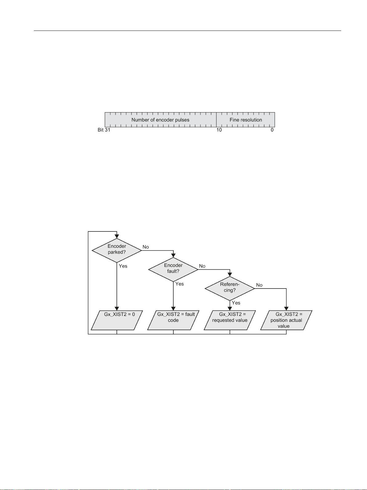
In the factory setting, the inverter transfers the encoder position actual value with a fine
resolution of 11 bits to the higher-level control system.
Figure 3-13 G1_XIST1 and G2_XIST1
The transferred encoder signal has the following properties:
● After the inverter power supply has been switched on, the encoder signal = 0.
● The higher-level control must be able to handle a counter overflow of the encoder signal.
In G1_XIST2 or G2_XIST2, the inverter transfers different values to the higher-level control
system:
Figure 3-14 G1_XIST2 and G2_XIST2
Fieldbuses
Function Manual, 04/2018, FW V4.7 SP10, A5E34229197B AE
31
Page 34

Communication via PROFIBUS and PROFINET
No.
Explanation
Possible cause
Observe the inverter message.
3
Encoder parking canceled
Parking was already requested.
3841
Encoder does not support the function
---
3.1 PROFIDRIVE profile - Cyclic communication
The inverter transfers the position values in the same format (encoder pulse number and fine
resolution) the same as G1_XIST1 and G2_XIST1.
Table 3- 2 Fault code
1 Encoder fault One or more encoder faults.
2 Zero-mark monitoring ---
4 Search for reference canceled
5 Retrieve reference value canceled
6 Flying referencing canceled
7 Retrieve measured value canceled
8 Position actual value transfer canceled
• Encoder has no zero mark (reference mark).
• Reference mark 2, 3 or 4 was requested.
• Switchover to "Flying measurement" was re-
quested during search for reference.
• Command "Read value x" requested during
search for reference mark.
• Inconsistent position measured value with dis-
tance-coded reference marks.
• More than four values were requested.
• No value requested.
• Requested value is not available.
• Reference cam has not been configured
• During "Flying referencing" a changeover was
made to search for reference.
• During "Flying referencing" a request was issued
"Read value x".
• More than one value was requested.
• No value requested.
• Requested value is not available.
• Encoder is parked.
• No absolute encoder available.
• Alarm bit in the absolute value protocol set.
Fieldbuses
32 Function Manual, 04/2018, FW V4.7 SP10, A5E34229197B AE
Page 35

Communication via PROFIBUS and PROFINET
3.1.5
Extend telegrams and change signal interconnection
Overview
Extending the telegram
Procedure
Freely interconnecting signals in the telegram
Procedure
3.1 PROFIDRIVE profile - Cyclic communication
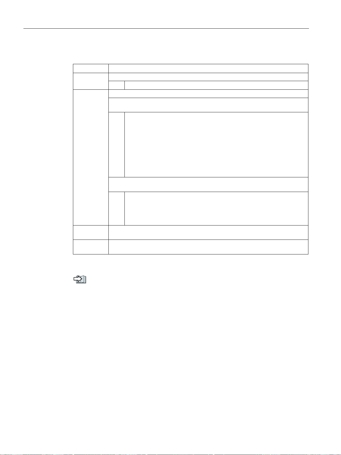
When you have selected a telegram, the inverter interconnects the corresponding signals
with the fieldbus interface. Generally, these interconnections are locked so that they cannot
be changed. However, with the appropriate setting in the inverter, the telegram can be
extended or even freely interconnected.
1. Set p0922 = 999.
2. Set parameter p2079 to the value of the corresponding telegram.
The interconnections contained in the telegram are locked.
3. Extend the telegram by "attaching" additional signals.
Interconnect additional PZD send words and PZD receive words with signals of your
choice via parameters r2050 and p2051.
You have extended the telegram.
❒
1. Set p0922 = 999.
2. Set p2079 = 999.
The interconnections contained in the telegram are enabled.
3. Interconnect additional PZD send words and PZD receive words with signals of your
choice via parameters r2050 and p2051.
You have freely interconnected the signals transferred in the telegram.
❒
Fieldbuses
Function Manual, 04/2018, FW V4.7 SP10, A5E34229197B AE
33
Page 36
Communication via PROFIBUS and PROFINET
Parameter
Parameter
Description
PROFIdrive telegram selection
PROFIdrive PZD telegram selection extended
999:
Free telegram configuration
inverter:
999:
Free telegram configuration
PROFIdrive PZD receive word
Received PZD (setpoints) in the word format
PROFIdrive PZD send word
Sent PZD (actual values) in the word format
3.1 PROFIDRIVE profile - Cyclic communication
p0922
999: Free telegram (message frame) configuration
p2079
The following values apply if you have still not enabled the "Basic positioner" function
in the inverter:
1:
Standard telegram 1, PZD-2/2
2:
Standard telegram 2, PZD-4/4
3:
Standard telegram 3, PZD-5/9
4:
Standard telegram 4, PZD-6/14
20:
Standard telegram 20, PZD-2/6
350:
SIEMENS telegram 350, PZD-4/4
352:
SIEMENS telegram 352, PZD-6/6
353:
SIEMENS telegram 353, PZD-2/2, PKW-4/4
354:
SIEMENS telegram 354, PZD-6/6, PKW-4/4
The following values apply if you have enabled the "Basic positioner" function in the
7:
Standard telegram 7, PZD-2/2
9:
Standard telegram 9, PZD-10/5
110:
SIEMENS telegram 110, PZD-12/7
111:
SIEMENS telegram 111, PZD-12/12
r2050[0…11]
p2051[0…16]
For further information about receive and send words, refer to the function block diagrams
2468 and 2470 in the List Manual.
Overview of the manuals (Page 232)
Fieldbuses
34 Function Manual, 04/2018, FW V4.7 SP10, A5E34229197B AE
Page 37
Communication via PROFIBUS and PROFINET
3.1.6
Data structure of the parameter channel
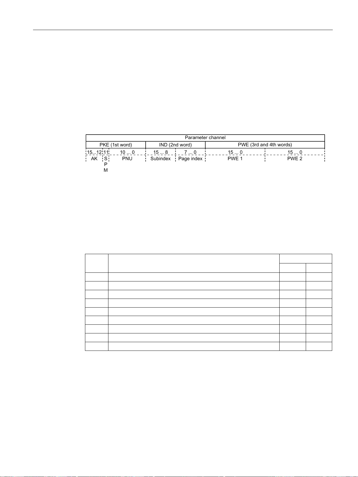
Structure of the parameter channel
AK: Request and response IDs
AK
Description
Response identifier
positive
negative
0
No request
0
7 / 8
1
Request parameter value
1 / 2
7 / 8
3
Change parameter value (double word)
2
7 / 8
4
Request descriptive element 1)
3
7 / 8
6
Request parameter value (field) 1)
4 / 5
7 / 8
7
Change parameter value (field, word) 1)
4
7 / 8
8 2)
Change parameter value (field, double word) 1)
5
7 / 8
1)
2)
We recommend that you use identifiers 6, 7, and 8.
3.1 PROFIDRIVE profile - Cyclic communication
The parameter channel consists of four words. The 1st and 2nd words transfer the
parameter number, index and the type of task (read or write). The 3rd and 4th words contain
the parameter content. The parameter contents can be 16-bit values (such as baud rate) or
32-bit values (e.g. CO parameters).
Bit 11 in the 1st word is reserved and is always assigned 0.
You can find application examples relating to the parameter channel at the end of this
section.
Bits 12 … 15 of the 1st The parameter channel words contain the request and response
identifier AK.
Table 3- 3 Request identifiers, control → inverter
2 Change parameter value (word) 1 7 / 8
2)
2)
9 Request number of field elements 6 7 / 8
The required element of the parameter is specified in IND (2nd word).
The following request IDs are identical: 1 ≡ 6, 2 ≡ 7 3 ≡ 8.
Fieldbuses
Function Manual, 04/2018, FW V4.7 SP10, A5E34229197B AE
35
Page 38
Communication via PROFIBUS and PROFINET
AK
Description
0
No response
2
Transfer parameter value (double word)
4
Transfer parameter value (field, word) 2)
5
Transfer parameter value (field, double word) 2)
6
Transfer number of field elements
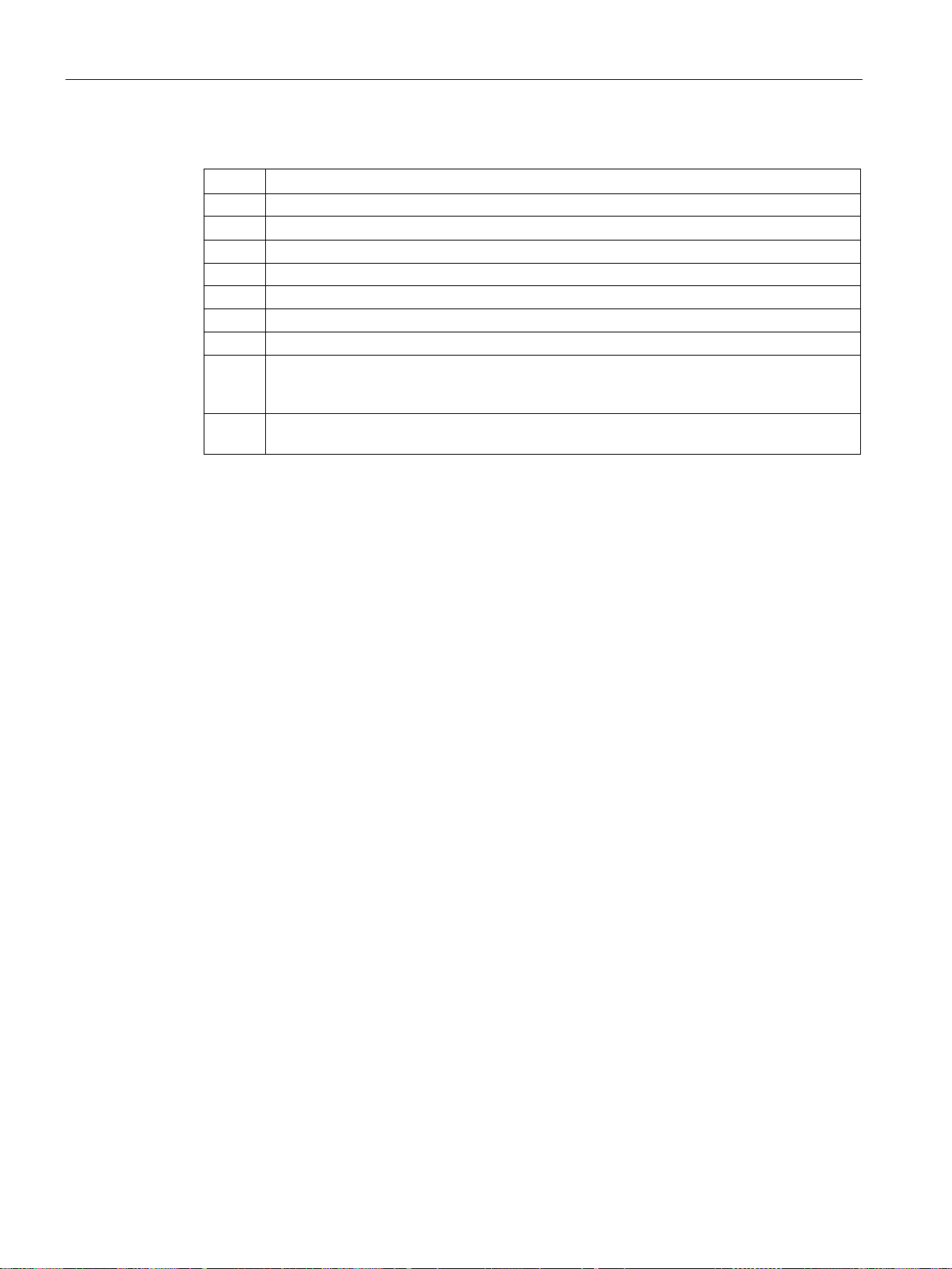
In the most significant word of the parameter channel, the inverter sends an error number to
the control, refer to the following table.
nel interface
1)
2)
The required element of the indexed parameter is specified in IND (2nd word).
3.1 PROFIDRIVE profile - Cyclic communication
Table 3- 4 Response identifiers, inverter → control
1 Transfer parameter value (word)
3 Transfer descriptive element 1)
7 Inverter cannot process the request.
8 No master controller status / no authorization to change parameters of the parameter chan-
The required element of the parameter is specified in IND (2nd word).
Fieldbuses
36 Function Manual, 04/2018, FW V4.7 SP10, A5E34229197B AE
Page 39

Communication via PROFIBUS and PROFINET
No.
Description
00 hex
Illegal parameter number (access to a parameter that does not exist)
Parameter value cannot be changed
a parameter value that cannot be
02 hex
Lower or upper value limit exceeded (change request with a value outside the value limits)
Incorrect subindex
04 hex
No array (access with a subindex to non-indexed parameters)
Incorrect data type
parameter)
Setting not permitted, only resetting
permission)
Descriptive element cannot be changed
value that cannot be changed)
0B hex
No master control (change request but with no master control, see also p0927.)
0C hex
Keyword missing
Request cannot be executed due to the operating state
rary reasons that are not specified)
Inadmissible value
for other permanent reasons, i.e. a parameter with defined individual values)
65 hex
Parameter number is currently deactivated (depending on the mode of the inverter)
66 hex
Channel width is insufficient (communication channel is too small for response)
Illegal parameter value
Request not included / task is not supported
in table "Request identifications controller → inverter")
No change access for a controller that is enabled
prevents a parameter change)
Write access only for commissioning (p0010 = 15) (operating state of the inverter prevents
a parameter change)
87 hex
Know-how protection active, access locked
Change request below the currently valid limit
the "absolute" limits, but is however below the currently valid lower limit)
Change request above the currently valid limit
the inverter power)
Change request not permitted
ble)
3.1 PROFIDRIVE profile - Cyclic communication
Table 3- 5 Error numbers for response identifier 7
01 hex
03 hex
05 hex
06 hex
07 hex
11 hex
14 hex
68 hex
6A hex
(change request for
changed)
(access to a subindex that does not exist)
(change request with a value that does not match the data type of the
(change request with a value not equal to 0 without
(change request to a descriptive element error
(access is not possible for tempo-
(change request with a value that is within the limits but which is illegal
(parameter can only assume certain values)
(the valid request identifications can be found
6B hex
86 hex
C8 hex
C9 hex
CC hex
. (The operating state of the inverter
(change request to a value that lies within
(example: a parameter value is too large for
(change is not permitted as the access code is not availa-
Fieldbuses
Function Manual, 04/2018, FW V4.7 SP10, A5E34229197B AE
37
Page 40
Communication via PROFIBUS and PROFINET
PNU (parameter number) and page index
Parameter number
PNU
Page index
0000 … 1999
0000 … 1999
0 hex
6000 … 7999
0000 … 1999
90 hex
10000 … 11999
0000 … 1999
A0 hex
20000 … 21999
0000 … 1999
50 hex
30000 … 31999
0000 … 1999
F0 hex
60000 … 61999
0000 … 1999
74 hex
Subindex
PWE: Parameter value or connector
PWE 1
PWE 2
Bit 15 … 0
Bit 15 … 8
Bit 7 … 0
0
0
8-bit value
0
16-bit value
32-bit value
Bit 15 … 0
Bit 15 … 10
Bit 9 … 0
nector
3.1 PROFIDRIVE profile - Cyclic communication
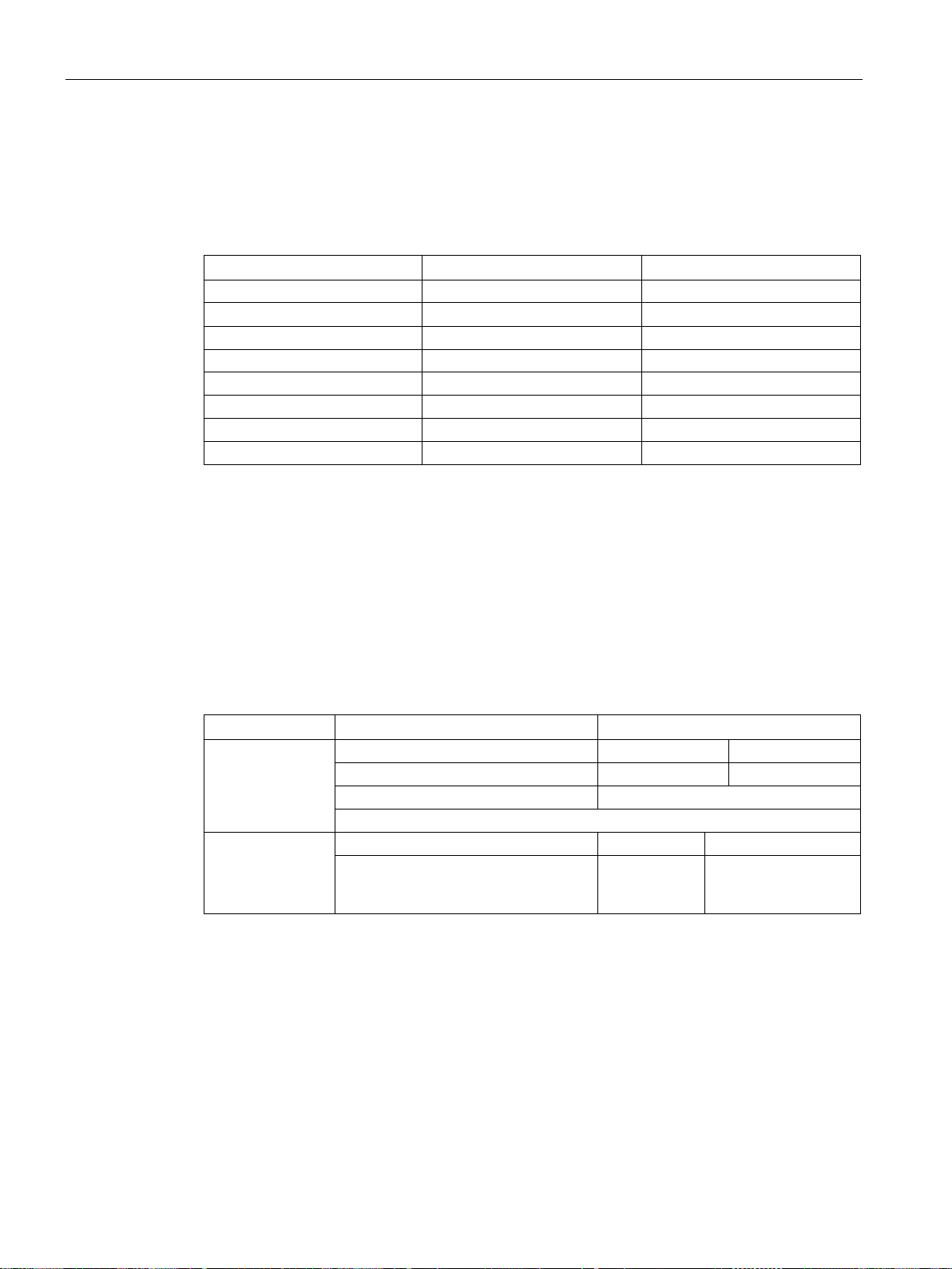
The parameter number is located in value PNU in the 1st word of the parameter channel
(PKE).
The page index is located in the 2nd word of the parameter channel (IND bit 7 … 0).
2000 … 3999 0000 … 1999 80 hex
8000 … 9999 0000 … 1999 20 hex
For indexed parameters, the parameter index is located in subindex (IND Bit 15 … 8) as
hexadecimal value.
Parameter values or connectors can be located in the PWE.
Table 3- 6 Parameter value or connector
Parameter value
Connector
Number of the connector 3F hex The index or bit field
number of the con-
Fieldbuses
38 Function Manual, 04/2018, FW V4.7 SP10, A5E34229197B AE
Page 41
Communication via PROFIBUS and PROFINET
3.1.6.1
Application examples
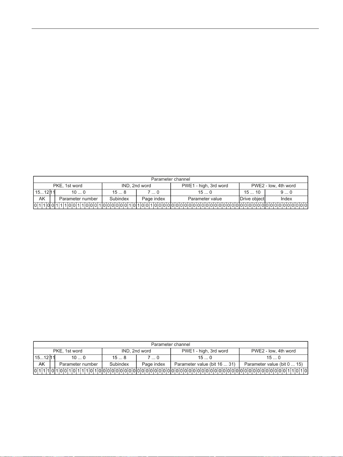
Read request: Read out serial number of the Power Module (p7841[2])
PKE, Bit 12 … 15 (AK): = 6
PKE, Bit 0 … 10 (PNU): = 1841
IND, bit 8 … 15 (subindex): = 2
IND, bit 0 … 7 (page index): = 90 hex
Write request: Change restart mode (p1210)
PKE, bit 12 … 15 (AK): = 7
PKE, bit 0 … 10 (PNU): = 4BA hex
IND, bit 8 … 15 (subindex): = 0 hex
IND, bit 0 … 7 (page index): = 0 hex
PWE1, bit 0 … 15: = 0 hex
PWE2, Bit 0 … 15: = 1A hex
3.1 PROFIDRIVE profile - Cyclic communication
To obtain the value of the indexed parameter p7841, you must fill the telegram of the
parameter channel with the following data:
●
●
Parameter number = PNU + offset (page index)
(7841 = 1841 + 6000)
●
●
● Because you want to read the parameter value, words 3 and 4 in the parameter channel
for requesting the parameter value are irrelevant. They should be assigned a value of 0,
for example.
Figure 3-15 Telegram for a read request from p7841[2]
(request parameter value (field))
(parameter number without offset)
(index of parameter)
(offset 6000 corresponds to 90 hex)
The restart mode is inhibited in the factory setting (p1210 = 0). In order to activate the
automatic restart with "acknowledge all faults and restart for an ON command", p1210 must
be set to 26:
●
●
●
●
●
●
Figure 3-16 Telegram, to activate the automatic restart with p1210 = 26
(change parameter value (field, word))
(1210 = 4BA hex, no offset, as 1210 < 1999)
(parameter is not indexed)
(offset 0 corresponds to 0 hex)
(26 = 1A hex)
Fieldbuses
Function Manual, 04/2018, FW V4.7 SP10, A5E34229197B AE
39
Page 42
Communication via PROFIBUS and PROFINET
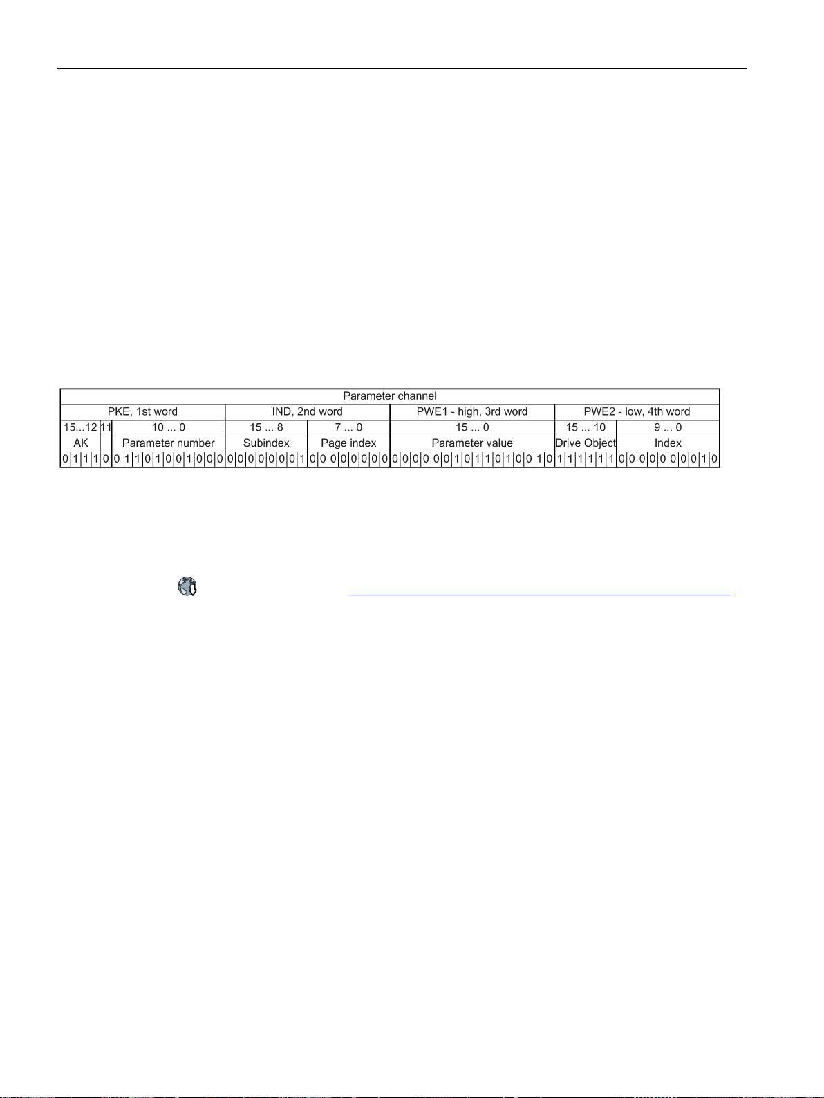
Write request: Assign digital input 2 with the function ON/OFF1 (p0840[1] = 722.2)
PKE, bit 12 … 15 (AK): = 7 hex
PKE, bit 0 … 10 (PNU): = 348 hex
IND, bit 8 … 15 (subindex): = 1 hex
IND, bit 0 … 7 (page index): = 0 hex
PWE1, Bit 0 … 15
2D2 hex
PWE2, Bit 10 … 15: = 3F hex
PWE2, Bit 0 … 9: = 2 hex
Application example, "Read and write to parameters"
3.1 PROFIDRIVE profile - Cyclic communication
In order to link digital input 2 with ON/OFF1, you must assign parameter p0840[1] (source,
ON/OFF1) the value 722.2 (DI 2). To do this, you must populate the telegram of the
parameter channel as follows:
●
●
●
●
●
●
●
Figure 3-17 Telegram, to assign DI 2 with ON/OFF1
: =
(change parameter value (field, word))
(722 = 2D2 hex)
(drive object - for SINAMICS G120, always 63 = 3f hex)
(Index of Parameter (DI 2 = 2))
Further information is provided on the Internet:
Application examples (https://support.industry.siemens.com/cs/ww/en/view/29157692)
(840 = 348 hex, no offset, as 840 < 1999)
(CDS1 = Index 1)
(offset 0 corresponds to 0 hex)
Fieldbuses
40 Function Manual, 04/2018, FW V4.7 SP10, A5E34229197B AE
Page 43

Communication via PROFIBUS and PROFINET
3.1.7
Slave-to-slave communication
Definitions
Publisher:
Subscriber:
Links and access points
Restrictions
Configuring slave-to-slave communication
Procedure
3.1 PROFIDRIVE profile - Cyclic communication
"Direct data exchange" is sometimes called "slave-to-slave communication" or "data
exchange broadcast". Here, slaves exchange data without any direct involvement of the
master.
Example: An inverter uses the actual speed value of another inverter as its speed setpoint.
●
●
●
● Direct data exchange in the current firmware version is only possible for inverters with
PROFIBUS communication.
● A maximum of 12 PZDs are permissible for each drive.
● A maximum of four links are possible from one subscriber to one or several publishers.
Slave, which sends data for direct data exchange.
Slave, which receives the data for direct data exchange from the publisher.
define the data that is used for direct data exchange.
1. In the control, define:
– Which inverters operate as publisher (sender) or subscriber (receiver)?
– Which data or data areas do you use for direct data exchange?
2. In the inverter, define:
How does the subscriber process the data transferred using direct data exchange?
You have now configured slave-to-slave communication.
❒
Fieldbuses
Function Manual, 04/2018, FW V4.7 SP10, A5E34229197B AE
41
Page 44
Communication via PROFIBUS and PROFINET
3.2
PROFIDRIVE profile - Acyclic communication
Note
Values in italics
Values in italics in the following tables mean that you have to adjust these values for a
specific request.
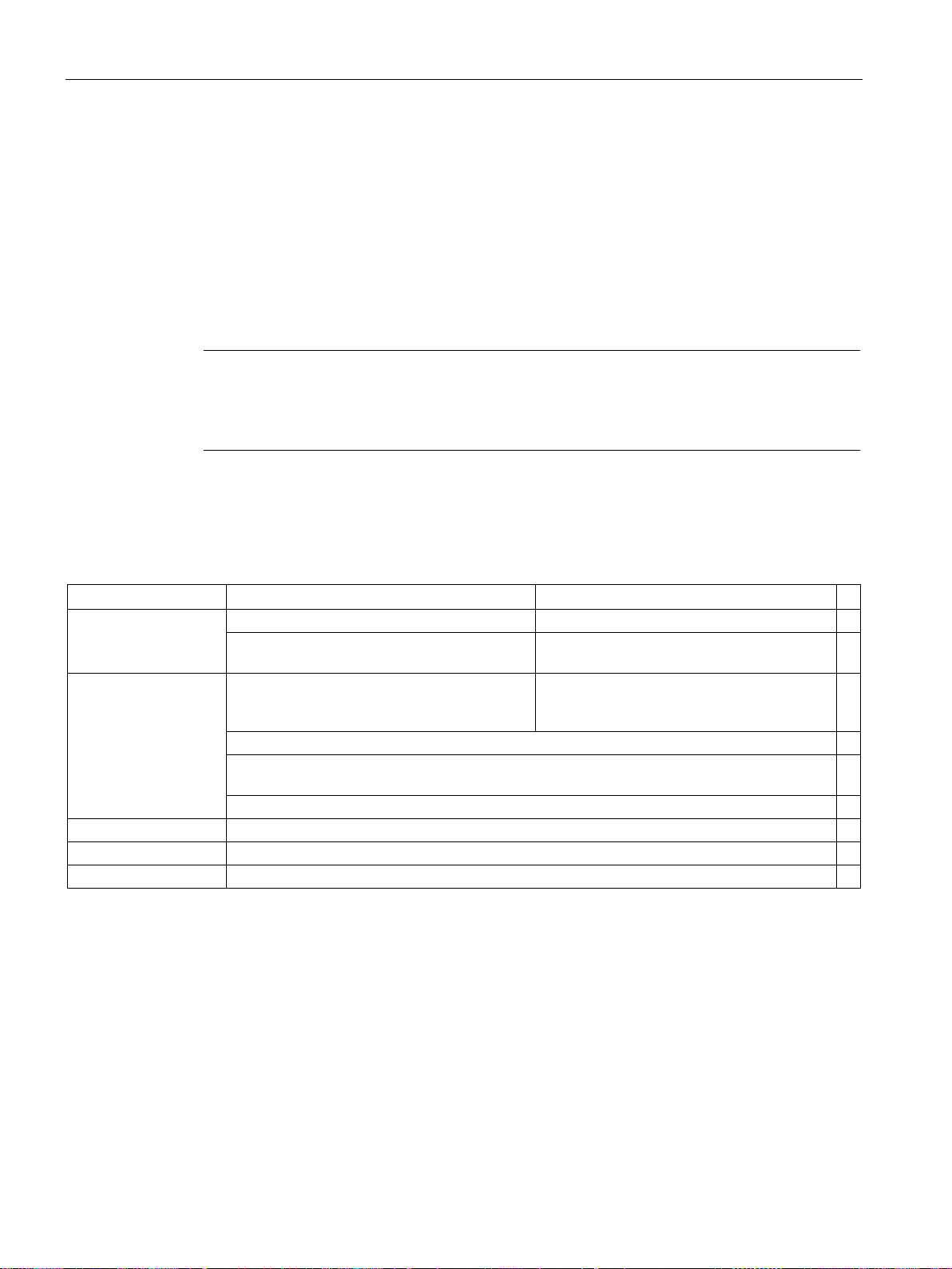
Reading parameter values
Data block
Byte n
Bytes n + 1
n
Header
Reference
00 hex ... FF hex
01 hex: Read job
0
01 hex
ways = 1)
Number of parameters (m)
Address, parameter 1
Attribute
20 hex:
Parameter description
Number of the indices
(For parameters without index: 00 hex)
Parameter number
0001 hex ... FFFF hex
6
Number of the 1st index
(for parameters without index: 0000 hex)
… … Address, parameter 2
…
…
… … …
Address, parameter m
…
…
3.2 PROFIDRIVE profile - Acyclic communication
The inverter supports the following types of acyclic communication:
● For PROFIBUS:
acyclic communication via data set 47
● For PROFINET:
acyclic communication via B02E hex and B02F hex
The maximum data length per request is 240 bytes.
Table 3- 7 Request to read parameters
(ID of drive objects, at G120 al-
10 hex:
Parameter value
0000 hex ... FFFF hex
00 hex ... EA hex
2
4
8
Fieldbuses
42 Function Manual, 04/2018, FW V4.7 SP10, A5E34229197B AE
Page 45

Communication via PROFIBUS and PROFINET
Data block
Byte n
Bytes n + 1
n
Header
Reference
01 hex
81 hex
execute the read request.
01 hex
ways = 1)
Number of parameters (m)
(identical to the read request)
Values, parameter 1
Format
Number of index values
number of error values
Value of the 1st index
error value 1
You can find the error values in a table at the end of this section.
Values, parameter 2
…
… …
Values, parameter m
…
3.2 PROFIDRIVE profile - Acyclic communication
Table 3- 8 Inverter response to a read request
02 hex
03 hex
04 hex
05 hex
06 hex
07 hex
08 hex
0A hex
0D hex
34 hex
35 hex
36 hex
41 hex
42 hex
43 hex
44 hex
… …
(identical to a read request)
(ID of drive objects, at G120 al-
: Integer8
: Integer16
: Integer32
: Unsigned8
: Unsigned16
: Unsigned32
: FloatingPoint
: OctetString
: TimeDifference
: TimeOfDay without date indication
: TimeDifference with date indication
: TimeDifference without date indication
: Byte
: Word
: Double word
: Error
or - for a negative response -
: Inverter has executed the read re-
quest.
: Inverter was not able to completely
or - for a negative
response -
0
2
4
6
Fieldbuses
Function Manual, 04/2018, FW V4.7 SP10, A5E34229197B AE
43
Page 46
Communication via PROFIBUS and PROFINET
Changing parameter values
Data block
Byte n
Bytes n + 1
n
Header
Reference
00 hex ... FF hex
02 hex: Change request
0
01 hex
ways = 1)
Number of parameters (m)
Address, parameter 1
10 hex
Number of indices
(00 hex and 01 hex are equivalents)
Parameter number
Number of the 1st index
0001 hex ... FFFF hex
8
…
…
Address, parameter 2
… … … …
Address, parameter m
…
Values, parameter 1
Format
43 hex:
Double word
Number of index values
Value of the 1st index
…
Values, parameter 2
…
… …
Values, parameter m
…
Data block
Byte n
Bytes n + 1
n
Header
Reference (identical to a change request)
02 hex (change request successful)
0
01 hex
ways = 1)
Number of parameters
request)
3.2 PROFIDRIVE profile - Acyclic communication
Table 3- 9 Request to change parameters
(ID of drive objects, at G120 al-
01 hex ... 27 hex
2
: Parameter value
0001 hex ... FFFF hex
02 hex:
03 hex:
04 hex:
05 hex:
06 hex:
07 hex:
08 hex:
0A hex:
0D hex:
34 hex
35 hex
36 hex
41 hex:
42 hex:
Integer 8
Integer 16
Integer 32
Unsigned 8
Unsigned 16
Unsigned 32
Floating Point
Octet String
Time Difference
: TimeOfDay without date indication
: TimeDifference with date indication
: TimeDifference without date indication
Byte
Word
4
00 hex ... EA hex
6
00 hex ... EA hex
Table 3- 10 Response, if the inverter has executed the change request
Fieldbuses
44 Function Manual, 04/2018, FW V4.7 SP10, A5E34229197B AE
(ID of drive objects, at G120 al-
(identical to a change
2
Page 47
Communication via PROFIBUS and PROFINET
Data block
Byte n
Bytes n + 1
n
Header
Reference
82 hex:
execute the write request)
01 hex
Number of parameters
Values, parameter 1
Format
block not executed)
Number of error values
error value 1
You can find the error values in the table at the end of this section.
error value 2
curred.
Values, parameter 2
...
... … …
Values, parameter m
...
Error values
Error
value 1
Meaning
00 hex
Illegal parameter number (access to a parameter that does not exist)
01 hex
Parameter value cannot be changed (change request for a parameter value that cannot be changed)
02 hex
Lower or upper value limit exceeded (change request with a value outside the value limits)
03 hex
Incorrect subindex (access to a parameter index that does not exist)
04 hex
No array (access with a subindex to non-indexed parameters)
05 hex
Incorrect data type (change request with a value that does not match the data type of the parameter)
Setting not permitted, only resetting
07 hex
Descriptive element cannot be changed (change request to a descriptive element that cannot be changed)
Description data not available
0B hex
No master control (change request but with no master control)
Text array does not exist
does not exist)
Request cannot be executed due to the operating state
not specified)
Inadmissible value
reasons, i.e. a parameter with defined individual values)
15 hex
Response too long (the length of the actual response exceeds the maximum transfer length)
Illegal parameter address
subindex or a combination of these)
17 hex
Illegal format (change request for an illegal or unsupported format)
3.2 PROFIDRIVE profile - Acyclic communication
Table 3- 11 Response if the inverter was not able to completely execute the change request
ways = 1)
40 hex: Zero (change request for this data
block executed)
44 hex: Error (change request for this data
Only for "Error" -
Only for "Error" Error value 2 is either zero, or it contains the number of the first index where the error oc-
(identical to a change request)
(ID of drive objects, at G120 al-
Table 3- 12 Error value in the parameter response
(Inverter was not able to completely
(identical to a change
request)
00 hex
01 hex or 02 hex
0
2
4
6
8
06 hex
09 hex
0F hex
11 hex
14 hex
16 hex
Fieldbuses
Function Manual, 04/2018, FW V4.7 SP10, A5E34229197B AE
(although the parameter value is available, the request is made to a text array that
(change request with a value that is within the limits but which is illegal for other permanent
(illegal or unsupported value for attribute, number of elements, parameter number,
(change request with a value not equal to 0 without permission)
(access to a description that does not exist, parameter value is available)
(access is not possible for temporary reasons that are
45
Page 48
Communication via PROFIBUS and PROFINET
Error
value 1
Meaning
Number of values not consistent
in the parameter address)
19 hex
Drive object does not exist (access to a drive object that does not exist)
20 hex
Parameter text cannot be changed
Service is not supported
A change request for a controller that has been enabled is not possible
6C hex
Unknown unit.
6E hex
Change request is only possible when the motor is being commissioned (p0010 = 3).
6F hex
Change request is only possible when the power unit is being commissioned (p0010 = 2).
Change request is only possible for quick commissioning (basic commissioning) (p0010 = 1).
71 hex
Change request is only possible if the inverter is ready (p0010 = 0).
72 hex
Change request is only possible for a parameter reset (restore to factory setting) (p0010 = 30).
73 hex
Change request possible only during commissioning of the safety functions (p0010 = 95).
74 hex
Change request is only possible when a technological application/unit is being commissioned (p0010 = 5).
75 hex
Change request is only possible in a commissioning state (p0010 ≠ 0).
76 hex
Change request is not possible for internal reasons (p0010 = 29).
77 hex
Change request is not possible during download.
81 hex
Change request is not possible during download.
82 hex
Accepting the master control is inhibited via BI: p0806.
Desired interconnection is not possible
nector input requires a float value)
Inverter does not accept a change request
85 hex
No access methods defined.
Write access only during commissioning of the data records (p0010 = 15)
vents a parameter change.)
87 hex
Know-how protection active, access locked
Change request below the currently valid limit
but is however below the currently valid lower limit)
C9 hex
Change request above the currently valid limit(example: a parameter value is too large for the inverter power)
CC hex
Change request not permitted (change is not permitted as the access code is not available)
3.2 PROFIDRIVE profile - Acyclic communication
18 hex
21 hex
6B hex
70 hex
(number of values of the parameter data to not match the number of elements
(illegal or not support request ID).
. (The inverter rejects the change request because the motor is switched on. Please observe the "Can be changed" parameter attribute (C1, C2, U,
T) in the List Manual.
Manuals and technical support (Page 232))
83 hex
84 hex
86 hex
C8 hex
(the connector output does not supply a float value although the con-
(inverter is busy with internal calculations. See parameter r3996 in
the inverter List Manual.
Manuals and technical support (Page 232))
(operating status of the inverter pre-
(change request to a value that lies within the "absolute" limits,
Fieldbuses
46 Function Manual, 04/2018, FW V4.7 SP10, A5E34229197B AE
Page 49

Communication via PROFIBUS and PROFINET
3.3
PROFIdrive profile - Diagnostic channels
3.3 PROFIdrive profile - Diagnostic channels
The inverters provide the diagnostics standardized for PROFIBUS and PROFINET. This
means that it is possible to directly output faults and alarms at an HMI (control system
screen).
Here, PROFINET offers more functions than PROFIBUS
● PROFIBUS: Faults without component assignment
● PROFINET: Faults and alarms with component assignment
The fault and alarm messages are saved in the inverter in the following parameters
● r0947[0 … 63]: Fault number
● r2122[0 … 63]: Alarm code
● r3120[0 … 63]: Components which are involved with the fault (only for PROFINET)
● r3121[0 … 63]: Components which are involved with the alarm (only for PROFINET)
The inverter transfers the messages in the sequence in which they occurred
The control generates the time stamp when the messages are received
Fieldbuses
Function Manual, 04/2018, FW V4.7 SP10, A5E34229197B AE
47
Page 50
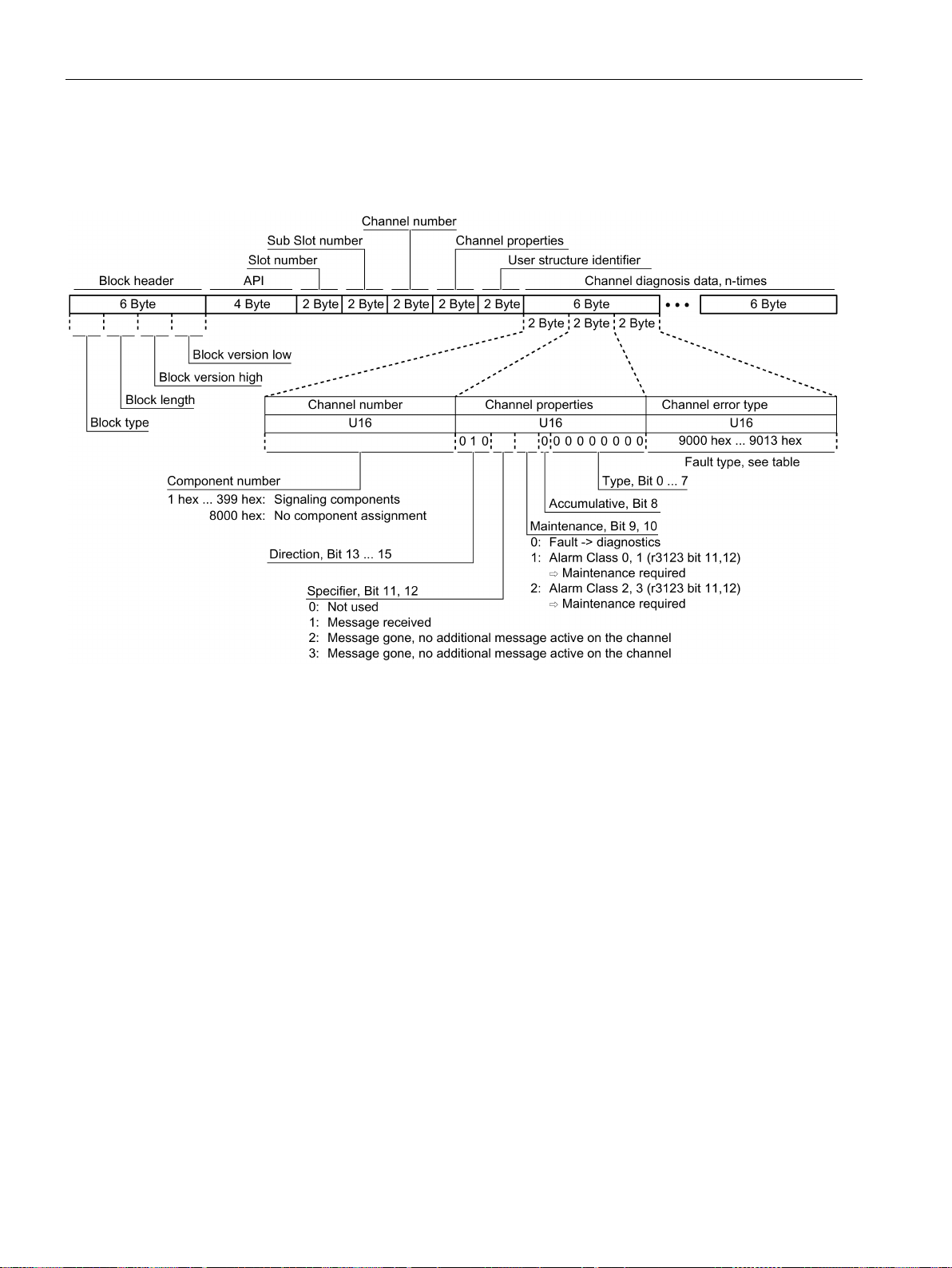
Communication via PROFIBUS and PROFINET
3.3.1
Diagnostics with PROFINET
available
9001 hex
Network fault
900B hex
Internal (DRIVE-CLiQ) communication error
9002 hex
Supply voltage fault
900C hex
Infeed faulted
9003 hex
DC link overvoltage
900D hex
Braking module faulted
9004 hex
Power electronics faulted
900E hex
Line filter faulted
the permissible range
9006 hex
Ground fault / inter-phase short circuit
9010 hex
Application / technological function faulted
/commissioning procedure
system
error
3.3 PROFIdrive profile - Diagnostic channels
PROFINET uses the channel diagnostics to transfer PROFIdrive message classes.
9000 hex Hardware/software error 900A hex Position/speed actual value incorrect or not
9005 hex Overtemperature of the electronic components 900F hex External measured value / signal state outside
9007 hex Motor overload 9011 hex Error in the parameterization / configuration
9008 hex Communication error to the higher-level control
9009 hex Safety monitoring channel has identified an
Figure 3-18 Structure of the channel diagnostics
9012 hex General drive fault
9013 hex Auxiliary unit faulted
Fieldbuses
48 Function Manual, 04/2018, FW V4.7 SP10, A5E34229197B AE
Page 51

Communication via PROFIBUS and PROFINET
Reading out diagnostics data
3.3 PROFIdrive profile - Diagnostic channels
The control requests the diagnostics data from the inverter using "Read data set", e.g. using
a read record with index 800C hex.
The following rules apply:
● 1 Message block (=ChannelDiagnosisData)
if (one or several) faults of the same message class are detected at the inverter
● n message blocks
if at the inverter, n faults of different message classes are detected
Further information is provided in the Internet: To access this link, you must be a member of
PROFIBUS and PROFINET International (PI).
PROFINET IO specification (http://www.profibus.com/nc/download/specifications-
standards/downloads/profinet-io-specification/display/)
Fieldbuses
Function Manual, 04/2018, FW V4.7 SP10, A5E34229197B AE
49
Page 52

Communication via PROFIBUS and PROFINET
3.3.2
Diagnostics with PROFIBUS
Standard diagnostics
Identifier-related diagnostics
Status messages/module status
Channel-related diagnostics
Diagnostics alarm with DS0 / DS1
Note
Precondition for diagnostics via PROFIBUS
3.3 PROFIdrive profile - Diagnostic channels
The following objects belonging to a diagnostics message in PROFIBUS
●
– Sequence: always at the first position of the message
– Length is always 6 bytes
●
– Sequence: at the second, third or fourth position
– Identification using the header,
– For SINAMICS G120, the length is always 2 bytes
●
– Sequence: at the second, third or fourth position
– Identification using the header,
– Length for SINAMICS G120:
- 5 bytes for configuration using GSD
- 6 bytes when configuring using the object library
●
– Sequence: at the second, third or fourth position
– Identification using the header,
– Length is always 3 bytes
●
– Sequence: always at the last position of the message
– Slot-specific the actual state of the slot responsible for the message is transferred.
The master must operate in the DPV1 mode for diagnostics via Profibus.
Fieldbuses
50 Function Manual, 04/2018, FW V4.7 SP10, A5E34229197B AE
Page 53
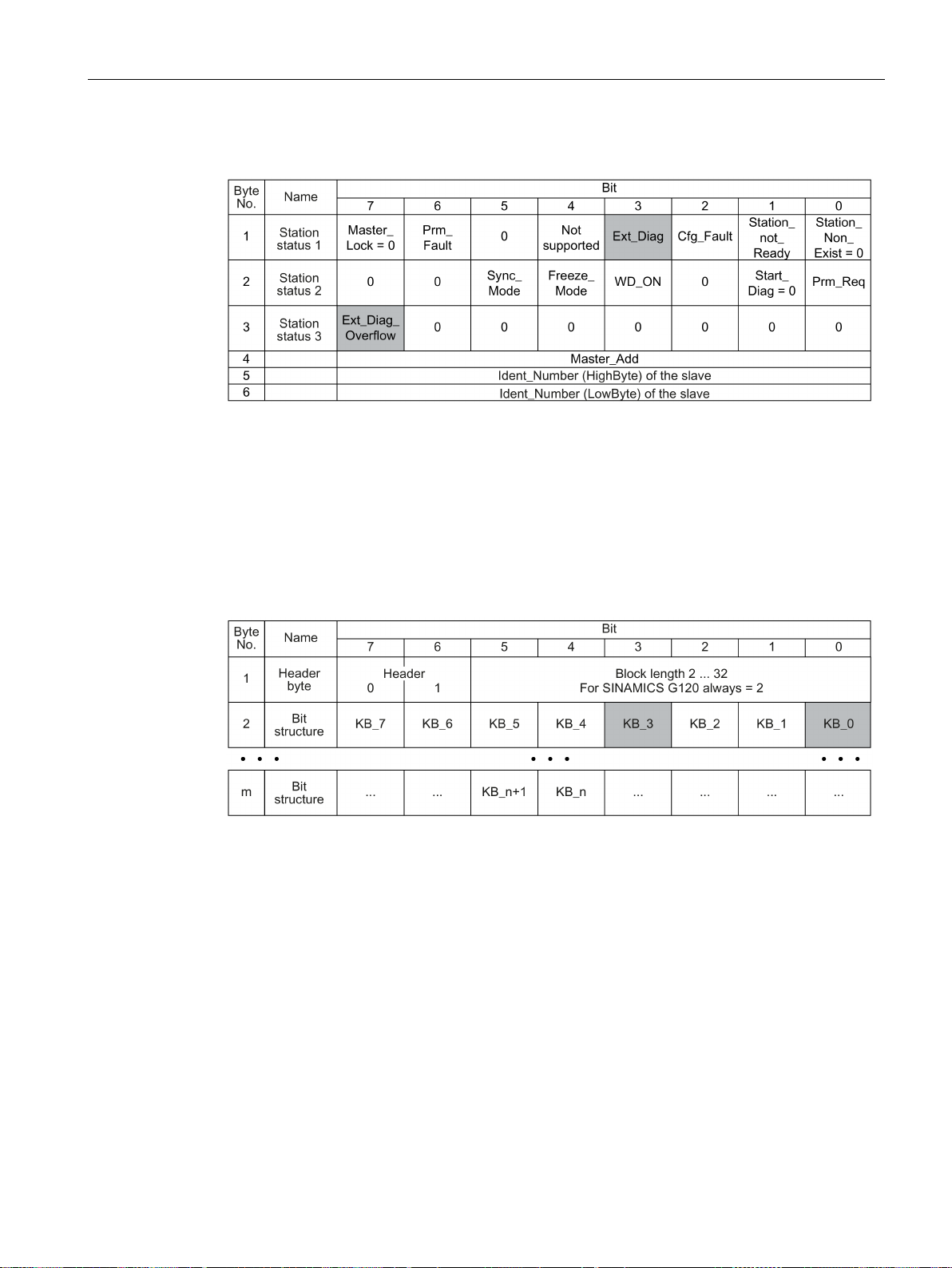
Communication via PROFIBUS and PROFINET
Default diagnostics
Ext_Diag
Ext_Diag_Overflow:
Identifier-related diagnostics
3.3 PROFIdrive profile - Diagnostic channels
The following values are decisive for the diagnostics:
•
- 0: No fault is active
- 1: At least one alarm or fault is active
•
Display for the diagnostics overflow in the slave (for more than 240 bytes)
: Group signal for diagnostics in the slave:
The identifier-related diagnostics provides a bit (KB_n) for each slot allocated when configuring the
device. If a diagnostics message is active at a slot, then it's KB_n = 1.
For G120 only one slot is allocated:
• KB_0 when configuring with the GSD
• KB_3 when configuring with the object manager
Fieldbuses
Function Manual, 04/2018, FW V4.7 SP10, A5E34229197B AE
51
Page 54
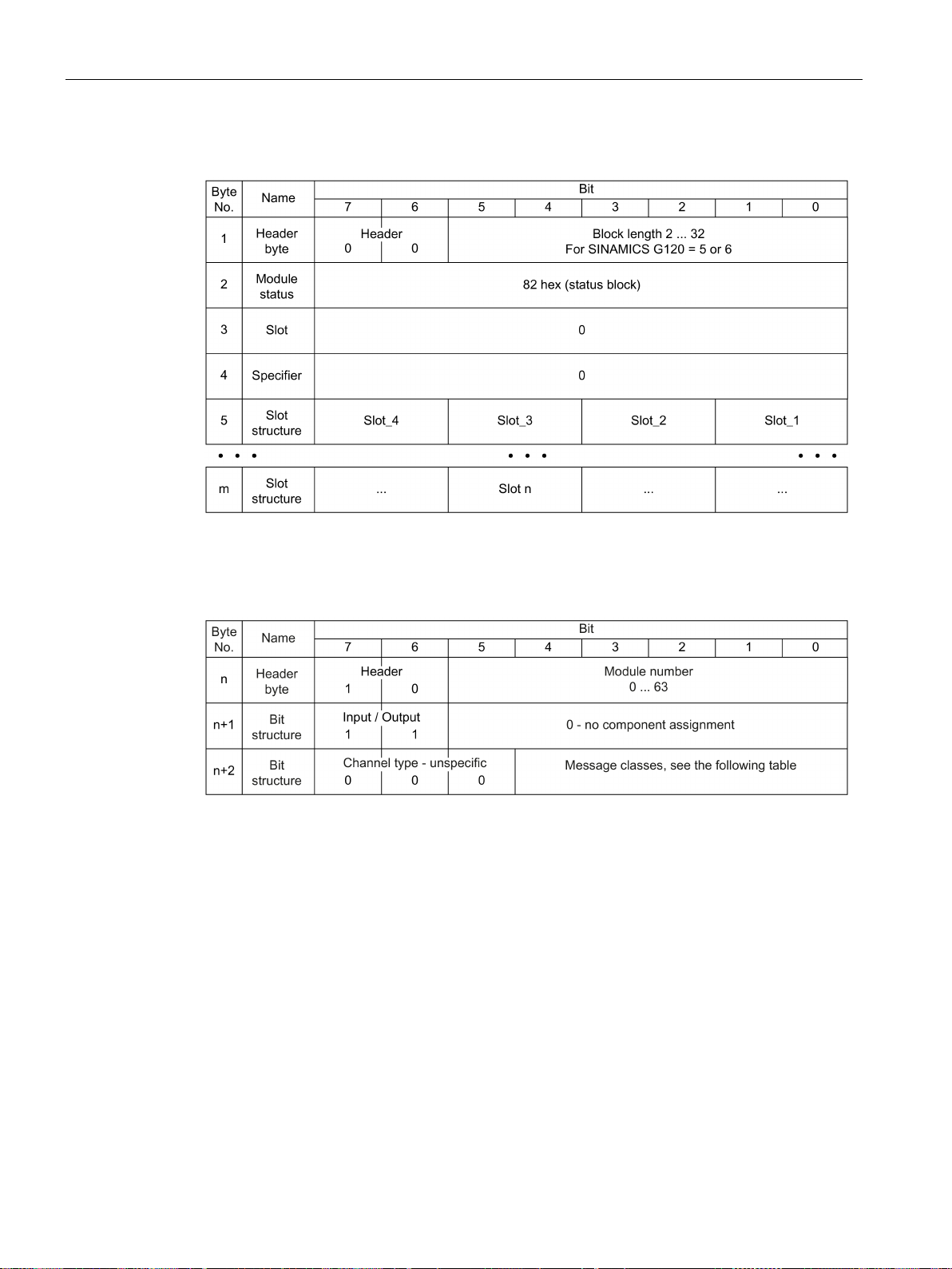
Communication via PROFIBUS and PROFINET
Status messages, module status
For G120, independent of the status, for all slots “00” is always output, i.e. valid user data.
Channel-related data
2
Undervoltage
22
Motor overload
3
Overvoltage
23
Commun. with controller faulted
9
Error
24
Safety monit. Detected an error
16
Hardware/software error
25
Act. Position/speed value error
17
Line supply/filter faulted
26
Internal communication faulted
18
DC link overvoltage
27
Infeed faulted
19
Power electronics faulted
28
Braking controller faulted
20
Electronic component overtemp.
29
External signal state error
21
Ground/phase fault detected
30
Application/function faulted
sage is displayed.
3.3 PROFIdrive profile - Diagnostic channels
When several faults are allocated at one inverter with the same message class, then only one mes-
Fieldbuses
52 Function Manual, 04/2018, FW V4.7 SP10, A5E34229197B AE
Page 55
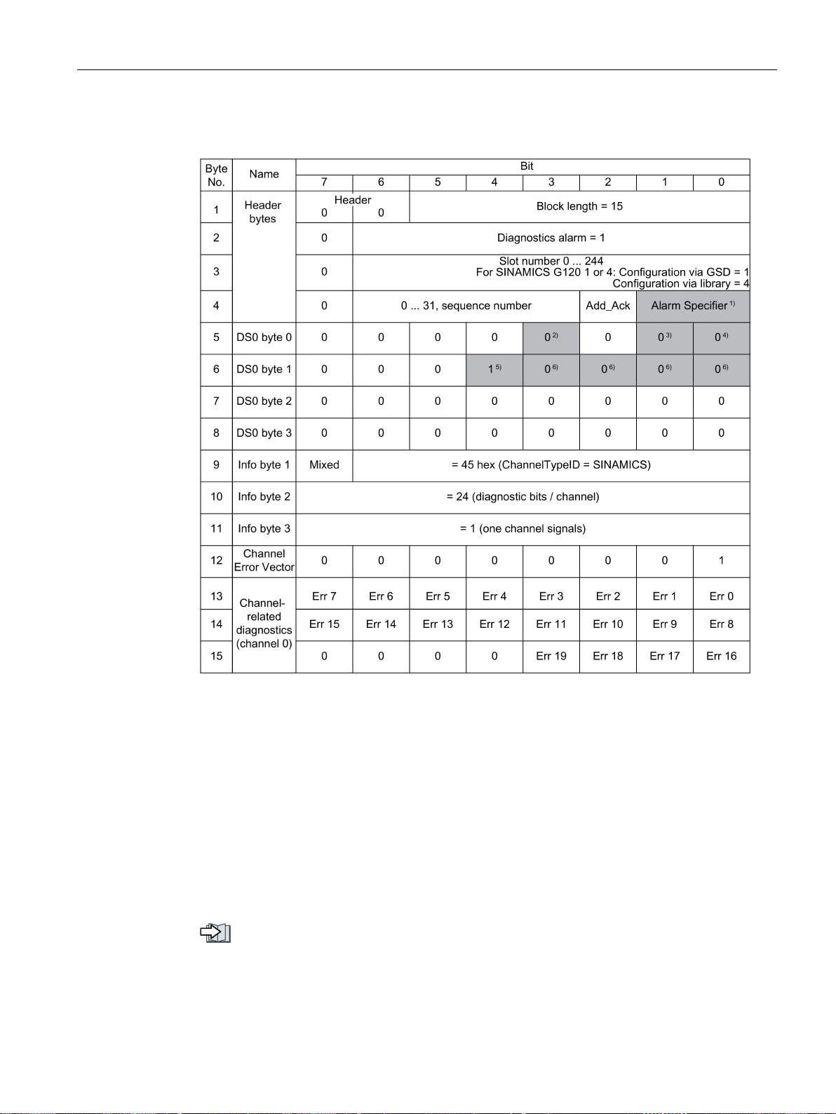
Communication via PROFIBUS and PROFINET
Diagnostics alarm with DS0 / DS1
3: Fault is resolved and the slot is not OK
1: Fault is active
1: Fault is active
3.3 PROFIdrive profile - Diagnostic channels
1) Alarm specifier
1: Fault is active and the slot is not OK
2: Fault is resolved and the slot is OK
2) Channel fault present
0: No fault is active
3) Internal fault
0: No fault is active
A table with the message classes is provided in the List Manual of the inverter.
Overview of the manuals (Page 232)
Fieldbuses
Function Manual, 04/2018, FW V4.7 SP10, A5E34229197B AE
4) Module fault
0: No fault is active
1: Fault is active
5) Channel information present
1: DS1 exists
6) Type of class module = 0011
(distributed)
53
Page 56
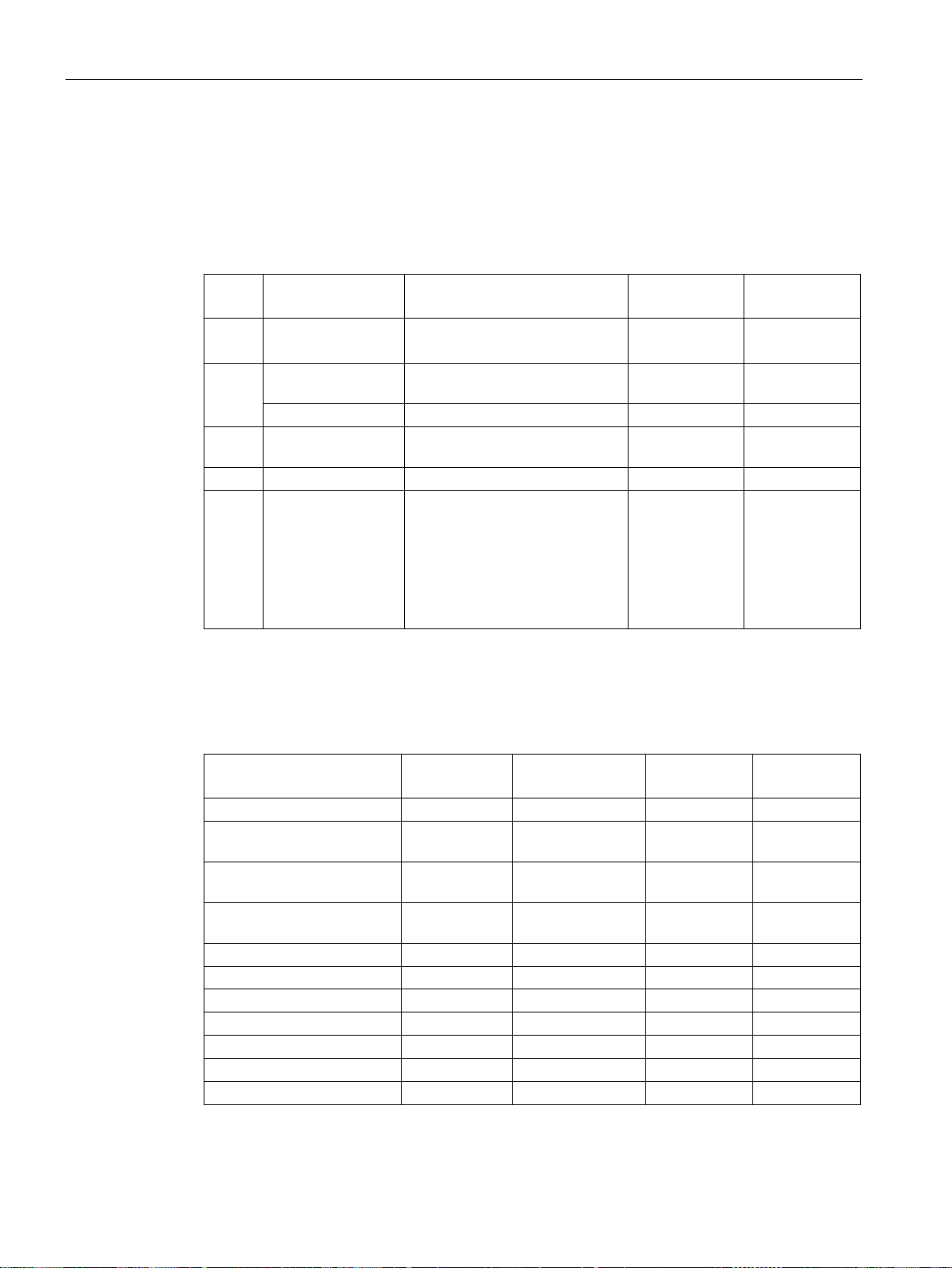
Communication via PROFIBUS and PROFINET
3.4
Identification & maintenance data (I&M)
I&M data
I&M
data
Format
Explanation
Associated
parameters
Example for the
content
u8[54] PROFINET
Visible String [22]
Location code
p8806[32 … 53]
"sc2+or45"
16:15"
I&M3
Visible String [54]
Any comment
p8808[0 … 53]
-
is p8805 = 0 is used.
I&M0
Designation
Format
Example for the
content
Valid for
PROFINET
Valid for
PROFIBUS
Manufacturer-specific
u8[10]
00 … 00 hex
---
✓
(=Siemens)
[20]
1FA0“
[16]
SOFTWARE_REVISION
char, u8[3]
„V“ 04.70.19
✓
✓
PROFILE_ID
u16
3A00 hex ✓ ✓
PROFILE_SPECIFIC_TYPE
u16
0000 hex ✓ ✓
IM_VERSION
u8[2]
01.02 ✓ ✓
IM_SUPPORTED
bit[16]
001E hex ✓ ✓
3.4 Identification & maintenance data (I&M)
The inverter supports the following identification and maintenance (I&M) data.
I&M0 u8[64] PROFIBUS
I&M1 Visible String [32] Plant/system identifier p8806[0 … 31] "ak12-
I&M2 Visible String [16] Date p8807[0 … 15] "2013-01-21
I&M4 Octet String[54] Check signature to track chang-
Inverter-specific data, read only - See below
ne.bo2=fu1"
p8809[0 … 53] Values of
es for Safety Integrated.
This value can be changed by
the user.
The test signature is reset to the
value generated by the machine
r9781[0] and
r9782[0]
When requested, the inverter transfers its I&M data to a higher-level control or to a PC/PG
with installed STEP 7 or TIA Portal.
Fieldbuses
54 Function Manual, 04/2018, FW V4.7 SP10, A5E34229197B AE
MANUFACTURER_ID u16 42d hex
ORDER_ID Visible String
SERIAL_NUMBER Visible String
HARDWARE_REVISION u16 0001 hex ✓ ✓
REVISION_COUNTER u16 0000 hex ✓ ✓
„6SL3246-0BA22-
„T-R32015957“ ✓ ✓
✓ ✓
✓ ✓
Page 57
Communication via PROFIBUS and PROFINET
3.5
S7 communication
Note
Number of S7 protocol connections
The inverter supports four S7 protocol connections. Two of these are required for Startdrive.
Each of the remaining two are available for access to the inverter via SIMATIC Panels.
3.5.1
Directly accessing a SINAMICS G120 converter from a SIMATIC panel
Example of direct access to the inverter via a SIMATIC panel
Requirements
3.5 S7 communication
Communication via the S7 protocol facilitates the following:
● Access to the inverter with Startdrive.
● Remote maintenance of the inverter with Startdrive across network boundaries.
(https://support.industry.siemens.com/cs/ww/en/view/97550333)
● Control of the inverter directly via SIMATIC Panels via PROFIBUS or PROFINET without
higher-level control.
Remote maintenance across network boundaries
Directly accessing a SINAMICS G120 converter from a SIMATIC panel (Page 55)
You want to use the SIMATIC panel to do the following:
● Switch the inverter on and off
● Enter a setpoint
● Display the actual value and status
You have installed the following software packages on your computer and made the
following settings:
● WINCCflex 2008 SP1 or higher
● Startdrive
● You have configured the inverter in Startdrive
● Inverter and panel are connected with one another via PROFIBUS or PROFINET.
● The same baud rates are set in the inverter and in the panel.
● The bus address configured in WinCC flexible matches the bus address of the inverter.
Fieldbuses
Function Manual, 04/2018, FW V4.7 SP10, A5E34229197B AE
55
Page 58

Communication via PROFIBUS and PROFINET
Adjusting settings in the inverter
Procedure
Make the following settings and releases so that the inverter can accept commands from
the panel:
Adjust the parameters for the ON/OFF1 command from the SIMATIC panel
Set parameters for the setpoint default
Actual value and status word
3.5 S7 communication
1.
– Set the two signal sources for OFF2 (p0844 and p0845) to 1:
– Set the two signal sources for OFF3 (p0848 and p0849) to 1:
– Set the releases for the ramp-up encoder
– Set the setpoint release
2.
– Set p0840[0] = 2094.0
– Now set p2099[0] = p2900
p0844 = 1
p0845 = 1
p0848 = 1
p0849 = 1
p1140 = 1
p1141 = 1
p1142 = 1
In doing so, you connect up the ON/OFF1 command using the Bit 0 of the BiCo
transformer 2094. The signal source for this parameter is p2099.
In doing so, you give the ON/OFF1 command by setting P2900 = 1 (ON) or 0 (OFF1)
3.
– Set
P1070 = 1001 (fixed setpoint 1 as setpoint)
P1016 = 1 (direct selection of the speed setpoint)
P1020 = 1 (speed fixed setpoint selection, Bit 0)
4.
No further settings are required by the inverter for displaying the speed list value (r0021)
and the status word (r0052).
You have now made the settings in the inverter.
❒
Fieldbuses
56 Function Manual, 04/2018, FW V4.7 SP10, A5E34229197B AE
Page 59

Communication via PROFIBUS and PROFINET
Settings at the SIMATIC panel
Procedure
Configure the connection using WinCC flexible
"SIMATIC S7 300/400"
Make the following settings for the configured connection:
ON/OFF1:
Setpoint
Actual value display
Status display
3.5 S7 communication
1.
– Enter a name for the connection
– Set the value in the "Active" column to "On"
– Select
as the communication driver.
– Set the value in the "Online" column to "On"
2.
– Select the interface (IF1 B for PROFIBUS, "Ethernet" for PROFINET)
– Set the baud rate for PROFIBUS
– Assign a bus address (PROFIBUS) or an IP address (PROFINET)
– Select S7ONLINE as the access point
– If no other control is connected to the inverter, select "Only master on bus"
– Select cyclical operation.
3.
– Create a variable for the parameter p2900, which refers to the address "Data module
2900 with the data word DBD 0 (data type double word)":
DB2900.DBD 0
You can switch ON/OFF1 on the panel using one or two buttons.
4.
– Create a variable for the parameter 1001, which refers to the address "Data module
1001 with the data word DBD 0 (data type real)":
DB1001.DBD 0
You can display it through an I/O field.
5.
– Create a variable for the parameter r0021, which refers to the address "Data module
21 with the data word DBD 0 (data type real)":
DB21.DBD 0
You can display it through an I/O field.
6.
– Create a variable for the parameter r0052, which refers to the address "Data module
52 with the data word DBW 0 (data type word)":
DB52.DBW 0
You can display it through an I/O field with a binary display, for example.
You have now made the most important settings in the SIMATIC panel.
❒
Fieldbuses
Function Manual, 04/2018, FW V4.7 SP10, A5E34229197B AE
57
Page 60
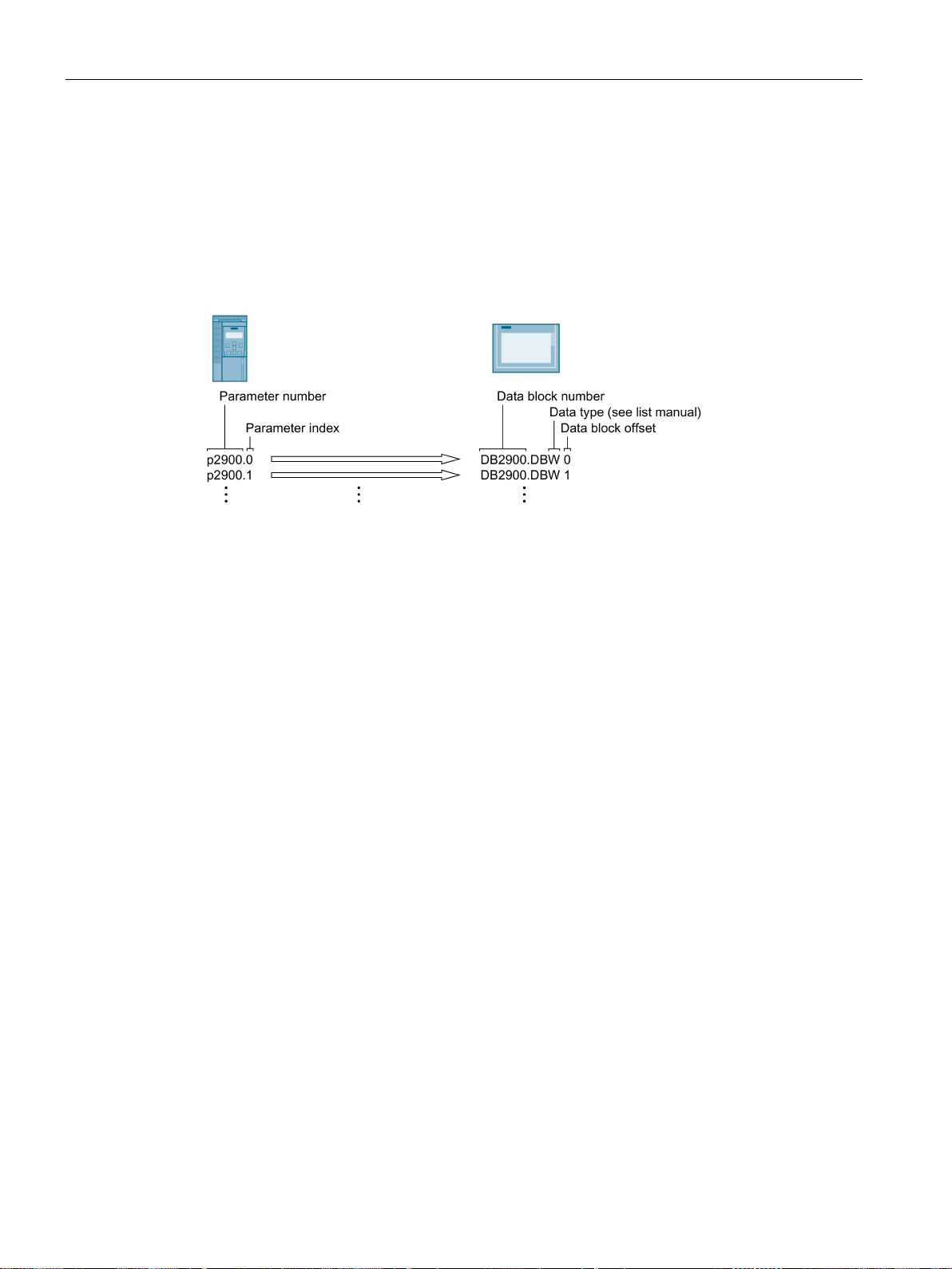
Communication via PROFIBUS and PROFINET
General information for accessing inverter parameters
3.5 S7 communication
You must create a variable with the following structure for each parameter that you want to
display or change using the SIMATIC panel: DBX DBY Z
● X: Data module number ≙ Parameter number
● Y: Data type (can be found in the parameter list)
● Z: Data module offset ≙ Parameter index
Figure 3-19 Accessing inverter parameters using a SINAMICS G120 as example
Fieldbuses
58 Function Manual, 04/2018, FW V4.7 SP10, A5E34229197B AE
Page 61
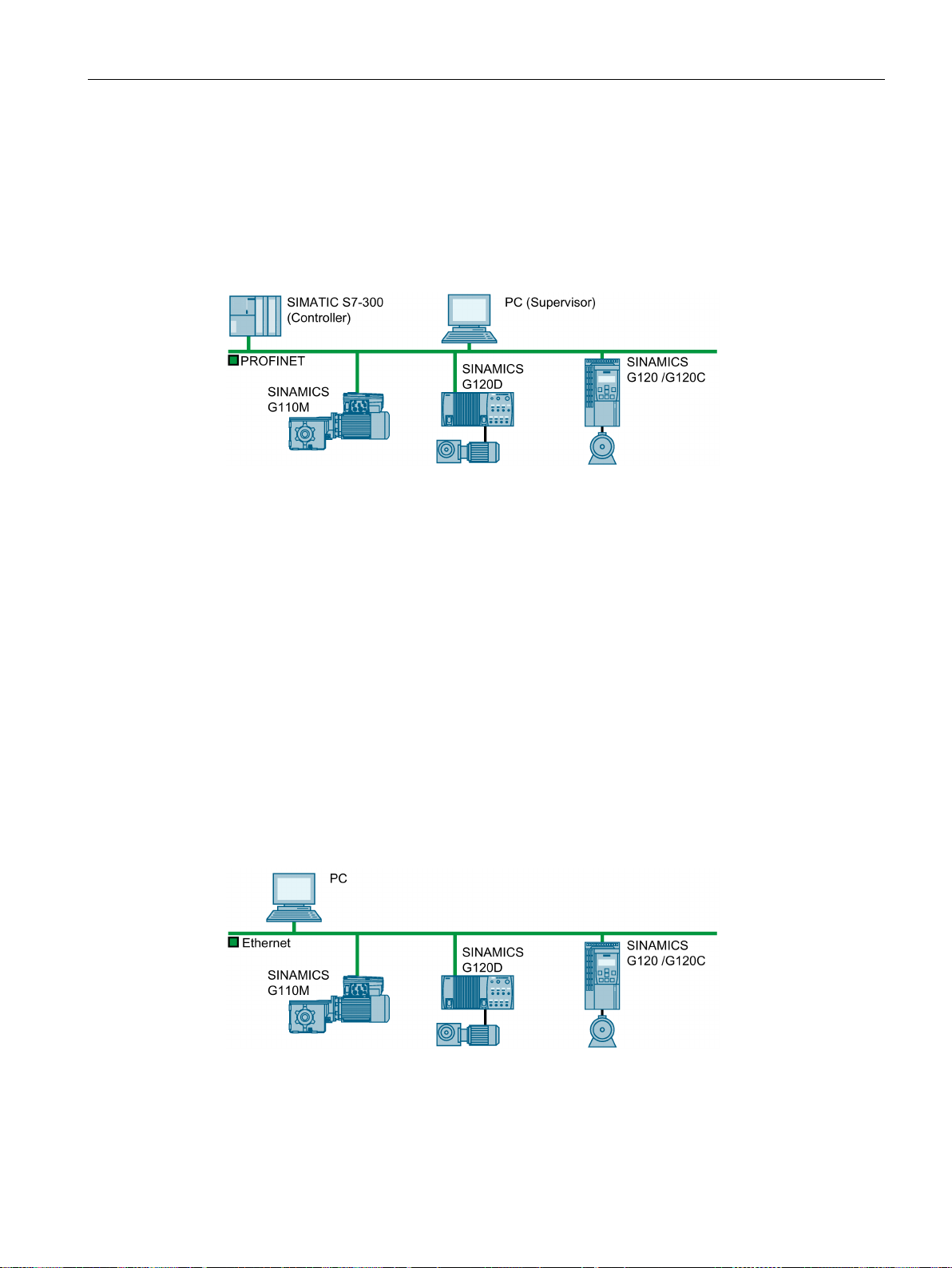
Communication via PROFIBUS and PROFINET
3.6
Communication via PROFINET
The inverter in PROFINET IO operation
The inverter as Ethernet node
3.6 Communication via PROFINET
You can either integrate the inverter in a PROFINET network or communicate with the
inverter via Ethernet.
Figure 3-20 The inverter in PROFINET IO operation
The inverter supports the following functions:
● RT
● IRT: The inverter forwards the clock synchronism, but does not support clock
synchronism.
● MRP: Media redundancy, impulsed with 200 ms. Requirement: Ring topology
● MRPD: Media redundancy, bumpless. Requirement: IRT and the ring topology created in
the control
● Diagnostic alarms in accordance with the error classes specified in the PROFIdrive
profile.
● Device replacement without removable data storage medium
● Shared Device for Control Units with fail-safe functions
Figure 3-21 The inverter as Ethernet node
Fieldbuses
Function Manual, 04/2018, FW V4.7 SP10, A5E34229197B AE
59
Page 62

Communication via PROFIBUS and PROFINET
Further information on PROFINET
3.6 Communication via PROFINET
Further information on PROFINET can be found on the Internet:
●
● PROFINET system description
PROFINET – the Ethernet standard for automation
(http://w3.siemens.com/mcms/automation/en/industrial-
communications/profinet/Pages/Default.aspx)
(https://support.industry.siemens.com/cs/ww/en/view/19292127)
Fieldbuses
60 Function Manual, 04/2018, FW V4.7 SP10, A5E34229197B AE
Page 63
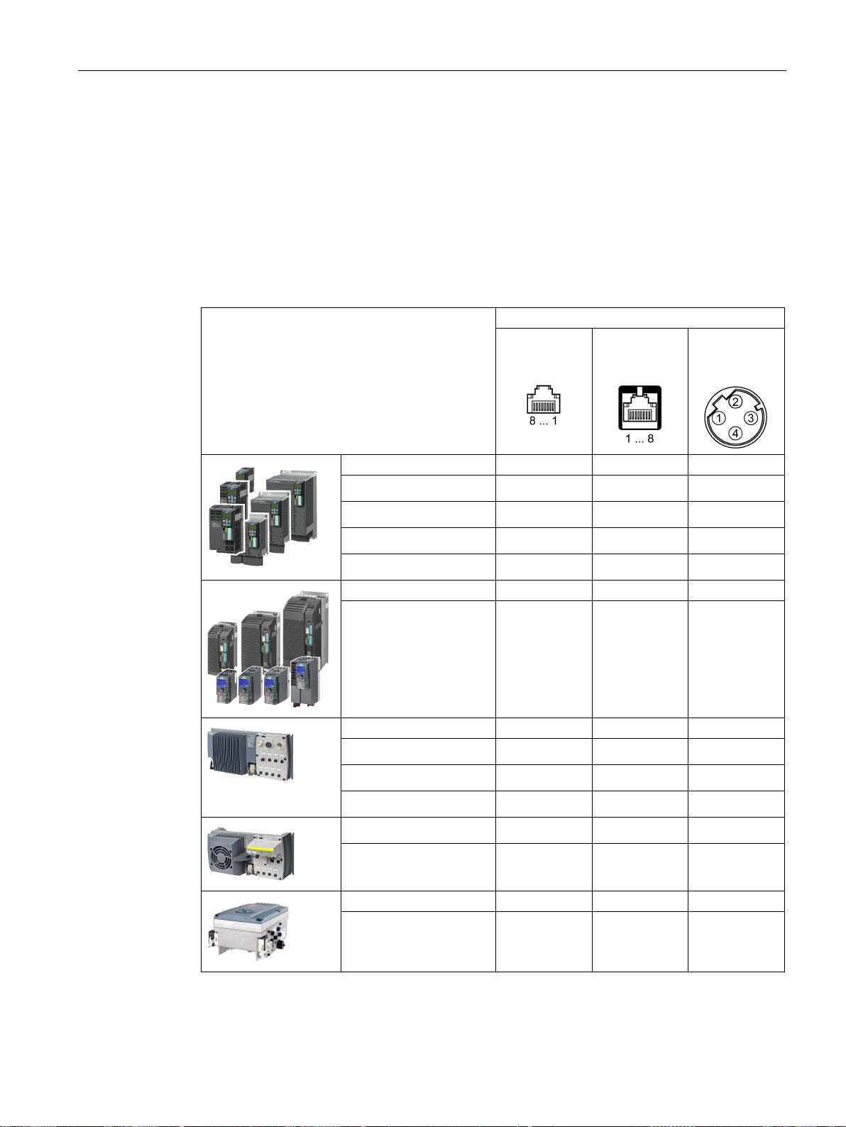
Communication via PROFIBUS and PROFINET
3.6.1
Converter with PROFINET interface
Connection via
G120
G120C
G120D
G110M
3.6 Communication via PROFINET
The pin assignment and the connectors that you require for your inverter are listed in the
following tables.
You can implement either a ring or line-type topology using the two sockets at the inverter.
You only require one of the two sockets at the beginning and end of a line.
You can use switches to realize other topologies.
Table 3- 13 Assignment table
Inverter/Control Unit
X150 P1/
X150 P2
(RJ45)
X03/X04
(RJ45)
X03/X04
(M12)
• CU230P-2 PN
• CU240E-2 PN
• CU240E-2 PN-F
• CU250S-2 PN
• G120C PN
• CU240D-2 PN
• CU240D-2 PN-F
• CU250D-2 PN-F
• CU240D-2 PN-F [PP]
• CU250D-2 PN-F [PP]
x
x
x
x
x
x
x
x
x
x
• CU240M PN
Fieldbuses
Function Manual, 04/2018, FW V4.7 SP10, A5E34229197B AE
x
61
Page 64
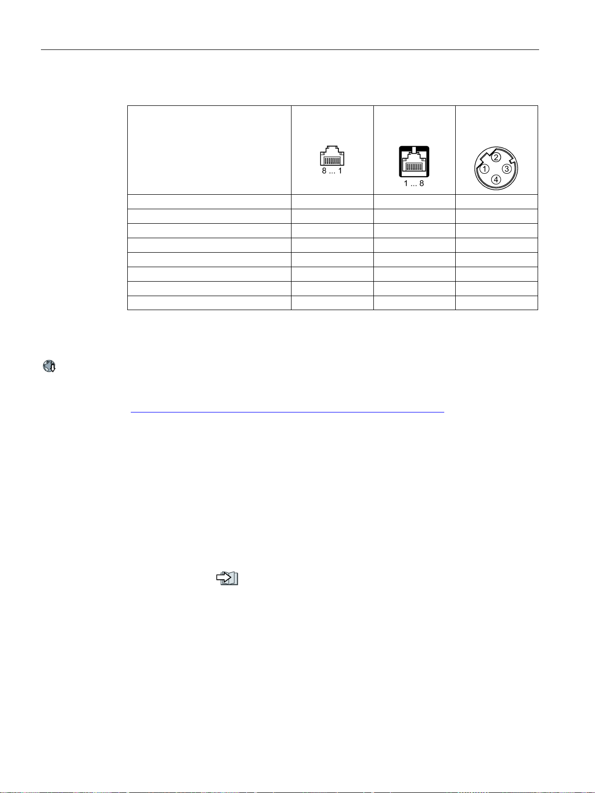
Communication via PROFIBUS and PROFINET
TX-, transmit data -
1 1 1
RX+, receive data +
3 2 2
TX+ Transmit data +
2 3 3
RX-, receive data -
6 6 4
---
4 4 ---
---
5 5 ---
---
8 8 ---
Recommended connector
3.6.2
Integrating inverters into PROFINET
Procedure
3.6 Communication via PROFINET
Table 3- 14 Connector pin assignments
Signal X150 P1/
X150 P2
(RJ45)
--- 7 7 ---
X03/X04
(RJ45)
X03/X04
(M12)
RJ45, IP20: 6GK1901-1BB10-2Ax0
Information for assembling the SIMATIC NET Industrial Ethernet FastConnect RF45 plug
180 can be found on the Internet:
Assembly instructions for the SIMATIC NET Industrial Ethernet FastConnect RJ45 plug
(http://support.automation.siemens.com/WW/view/en/37217116/133300)
To connect the inverter to a control via PROFINET, proceed as follows:
1. Integrate the inverter in the bus system (e.g. ring topology) of the control using
PROFINET cables and the two PROFINET sockets X150-P1 and X150-P2 or X03 and
X04.
The position of the sockets is available in the operating instructions for the inverter.
Pin assignment:
Converter with PROFINET interface (Page 61).
The maximum permitted cable length from the previous station and to the subsequent
one is 100 m.
2. Externally supply the inverter with 24 V DC through terminals 31 and 32 or via X01.
The external 24 V supply is only required if communications with the control system
should also operate when the line voltage is switched off.
You have now connected the inverter to the control system via PROFINET
❒
Fieldbuses
62 Function Manual, 04/2018, FW V4.7 SP10, A5E34229197B AE
Page 65
Communication via PROFIBUS and PROFINET
3.6.3
PROFINET IO operation
3.6.3.1
What do you have to set for communication via PROFINET?
Questions
Answer/description
(Page 62)
control (Page 63)
in the higher-level control?
Communication with the control, even when the line voltage is switched off
3.6.3.2
Configuring communication to the control
Configuring the communication using SIMATIC S7 control
Configuring the communication using a non-Siemens control
3.6 Communication via PROFINET
Check the communication settings using the following table. If you answer "Yes" to the
questions, you have correctly set the communication settings and can control the inverter via
the fieldbus.
Is the inverter correctly connected to the bus network?
Do the IP address and device name in the inverter
and control match?
Is the same telegram set in the inverter the same as
Are the signals that the inverter and the control
exchange via PROFINET correctly interconnected?
Integrating inverters into PROFINET
Configuring communication to the
Setting the telegram in the control
Interconnect signals in the inverter in conformance with PROFIdrive.
PROFIDRIVE profile - Cyclic communi-
cation (Page 17)
PROFIDRIVE profile - Acyclic commu-
nication (Page 42)
If, in your plant or system, communication with the control system should continue to function
even when the line voltage is switched off, then you must externally supply the
inverter/Control Unit with 24 V DC. To do this, use terminals 31 and 32 – or connector X01.
You can find additional details in the operating instructions for the inverter or the Control
Unit.
If the inverter is not included in the hardware library, you have the following options:
● Install the most up to date Startdrive version
● Install the GSDML of the inverter using "Options/Manage general station description
(GSD)" in the components catalog.
1. Import the device file (GSDML) of the inverter into the engineering tool for your control
system.
2. Configure the communication.
Fieldbuses
Function Manual, 04/2018, FW V4.7 SP10, A5E34229197B AE
63
Page 66
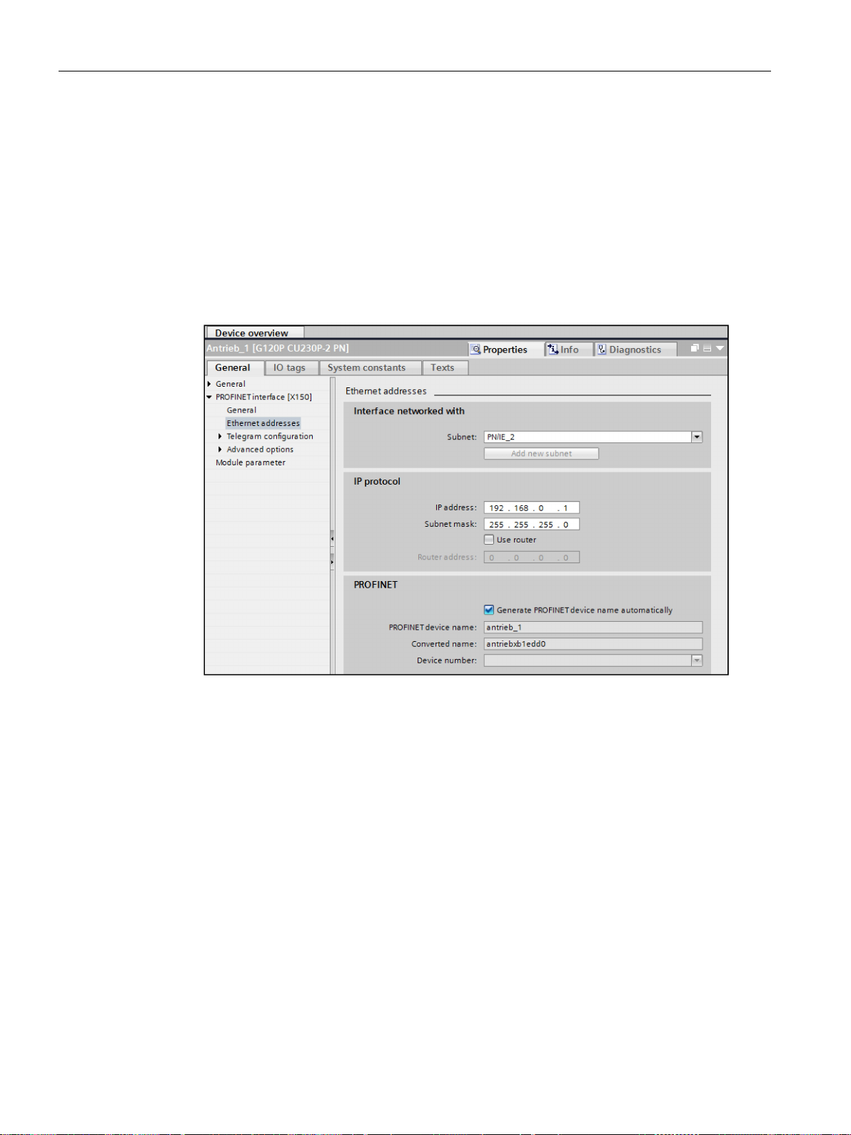
Communication via PROFIBUS and PROFINET
Configuring communication with Startdrive
3.6 Communication via PROFINET
Proceed as follows to make the settings for communication with the control system.
● Activate the following windows in Startdrive: "View/Project tree" and "View/Inspector
window".
● Open the drive in the project tree and double click on "Device configuration".
This opens the dialog in the inspector window for setting the PROFINET interface.
● Click on "Ethernet addresses".
● Enter the appropriate values.
You have configured communication with the control system.
❒
You can enter or read out data directly via the parameter view. To do this, select the
"Communication" parameter group and the "Show advanced parameters" option.
Fieldbuses
64 Function Manual, 04/2018, FW V4.7 SP10, A5E34229197B AE
Page 67

Communication via PROFIBUS and PROFINET
3.6.3.3
Installing GSDML
Procedure
3.6.3.4
Activating diagnostics via the control
3.6.4
PROFIenergy
3.6 Communication via PROFINET
1. Save the GSDML to your PC.
– With Internet access:
GSDML (https://support.industry.siemens.com/cs/ww/en/ps/13222/dl)
– Without Internet access:
Insert a memory card into the inverter.
Set p0804 = 12.
The inverter writes the GSDML as zipped file (*.zip) into directory
/SIEMENS/SINAMICS/DATA/CFG on the memory card.
2. Unzip the GSDML file on your computer.
3. Import the GSDML into the engineering system of the controller.
You have now installed the GSDML in the engineering system of the controller.
❒
The converter provides the functionality to transmit fault and alarm messages (diagnostic
messages) to the higher-level control according to the PROFIdrive error classes.
The functionality must be selected in the higher-level controller and activated by powering
up.
PROFIenergy is an energy management standard for production plants, based on the
PROFINET communication protocol. The functionality is certified and described in the
PROFIenergy profile of the PNO.
The control transfers the PROFIenergy commands in acyclic operation to the inverter in data
set 80A0 hex.
The inverters support the PROFIenergy profile V1.1 and the function unit class 3.
Parameters r5600 to p5614 are reserved for PROFIenergy functions in the inverter.
An application example for energy savings with PROFIenergy is available in the Internet at:
PROFIenergy - saving energy with SIMATIC S7
(https://support.industry.siemens.com/cs/ww/en/view/41986454)
Fieldbuses
Function Manual, 04/2018, FW V4.7 SP10, A5E34229197B AE
65
Page 68

Communication via PROFIBUS and PROFINET
3.6.4.1
General inverter behavior when in the PROFIenergy energy-saving mode
3.6.4.2
Supported PROFIenergy energy-saving modes
PROFIenergy energy-saving mode 2
PROFIenergy energy-saving mode 1
3.6 Communication via PROFINET
● When the PROFIenergy energy-saving mode is active, the inverter issues alarm A08800.
● If the PROFIenergy energy-saving mode is active, the RDY-LED flashes green as follows:
500 ms on, 3000 ms off.
● When the PROFIenergy energy-saving mode is active, the inverter does not send any
diagnostic alarms.
● If the bus connection to the control system is interrupted while the inverter is in the
energy-saving mode, the inverter exits the energy-saving mode and resumes normal
operation.
● The inverter changes into normal operation if the control system goes into the stop
condition while the inverter is in the energy-saving mode.
G110M, G120 and G120C inverters support the PROFIenergy energy-saving mode 2.
G120D inverters support the PROFIenergy energy-saving mode 1.
Parameter r5600 shows the active PROFIenergy energy-saving mode.
Connector parameter r5613 indicates whether the PROFIenergy energy-saving mode is
active. You can set additional responses using these parameters.
PROFIenergy energy-saving mode 1 is an expansion of PROFIenergy energy-saving mode
2.
With PROFIenergy energy-saving mode 1, the inverter offers the following additional
functions:
● The inverter switches off the power supply for its digital outputs if they are not
interconnected with r5613.x (displays the energy-saving mode) or are being used as
safety-relevant outputs.
● The inverter switches off the supply voltage of its encoders unless they are HTL encoders
assigned to the position controller.
Fieldbuses
66 Function Manual, 04/2018, FW V4.7 SP10, A5E34229197B AE
Page 69
Communication via PROFIBUS and PROFINET
3.6.4.3
Settings and displays for PROFIenergy in the inverter
Pause time
Inhibiting PROFIenergy
Transition into the energy-saving mode from the PROFIdrive states ready (S3) and operation (S4)
PROFIenergy measured values
PROFIenergy
SINAMICS source parameters
Range of
values
Measured value
Accuracy
Unit
ID
Name
Domain
Class
Number
Name
34
Active power
1
12 W r0032
Active power smoothed
r2004
200
Active energy import
2
11
Wh
r0039[1]
Energy accepted
-
3.6 Communication via PROFINET
● Minimum pause time: p5602
– When the pause time, which is sent using command "Start_Pause", is equal to or
greater than the value in p5602[1], then the inverter goes into the energy-saving
mode.
– When the pause time is less than p5602[1], the inverter rejects the command
"Start_Pause" with 50 hex (no appropriate pause mode).
● Maximum pause time: p5606
If you set p5611.0 = 1, you block the response of the inverter to PROFIenergy control
commands. In this case, the inverter rejects the "Start_Pause" command with 50 hex (no
appropriate pause mode).
If you set p5611.2 = 1, you allow the transition into the energy-saving mode from the
PROFIdrive states ready (S3) and operation (S4).
To do so, you must set one of the following settings:
● p5611.1 = 1: With the transition to the energy-saving mode, the inverter issues an OFF1
command and enters the start-inhibit state (S1).
● p5611.1 = 0: You can use p5614 to interconnect a signal source that switches the inverter
off and places it in the start inhibited state (S1).
If the control sends the command "End_Pause" or "Start_Pause" with a pause time of 0, then
the inverter does not restart, even if the appropriate enable signals are still set.
An OFF1/on command is required in order that the inverter restarts.
166 Power factor 1 12 1 r0038 Smoothed power factor 0 … 1
Fieldbuses
Function Manual, 04/2018, FW V4.7 SP10, A5E34229197B AE
67
Page 70

Communication via PROFIBUS and PROFINET
3.6.4.4
Control commands and status queries
PROFIenergy control commands
PROFIenergy status requests
3.6 Communication via PROFINET
● Start_Pause
Dependent on the pause duration, switches into the energy-saving mode.
– For p5611.2 = 0, from operating states S1 (switching on inhibited) or S2 (ready to
switch on)
– For p5611.2 = 1, also from operating states S3 (ready) or S4 (operation).
● Start_Pause_with_time_response
Dependent on the pause duration switches into the energy-saving mode and also
specifies the transition times in the command response.
– For p5611.2 = 0, from operating states S1 (switching on inhibited) or S2 (ready to
switch on)
– For p5611.2 = 1, also from operating states S3 (ready) or S4 (operation).
● End_Pause
Switches from energy-saving mode to the operating state.
Cancels the switching from the operating state to the energy-saving mode.
● List_Energy_Saving_Modes
Determines all supported energy-saving modes.
● Get_Mode
Determines information about the selected energy-saving mode.
● PEM_Status
Determines the current PROFIenergy status.
● PEM_Status_with_CTTO
Determines the current PROFIenergy status, such as the PEM_Status, together with the
regular transition time to the operating state.
● PE_ldentify
Determines the supported PROFIenergy commands.
● Query_Version
Shows the implemented PROFIenergy profile.
● Get_Measurement_List
This command returns the measured value IDs that can be accessed using the
"Get_Measurement_Values" command.
● Get_Measurement_List_with_object_number
This command returns the measured value IDs and the associated object number that
can be accessed using the "Get_Measurement_Values_with_object_number" command.
Fieldbuses
68 Function Manual, 04/2018, FW V4.7 SP10, A5E34229197B AE
Page 71

Communication via PROFIBUS and PROFINET
Error values
Error
value 1
Meaning
001 hex
Invalid Service_Request_ID
Invalid Modifier
04 hex
Invalid Data_Structure_Identifier_RQ
06 hex
No PE energy-saving mode supported
07 hex
Response too long
08 hex
Invalid Block Header
50 hex
No suitable energy-saving mode available
51 hex
Time is not supported
52 hex
Impermissible PE_Mode_ID
53 hex
No switch to energy saving mode because of state operate
54 hex
service or function temporarily not available
3.6 Communication via PROFINET
● Get_Measurement_Values
The command returns the requested measured value using the measured value ID
● Get_Measurement_Values_with_object_number
The command returns the requested measured values using the measured value ID and
the object number. The object number corresponds to the drive object ID.
Table 3- 15 Error values in the parameter response
03 hex
Fieldbuses
Function Manual, 04/2018, FW V4.7 SP10, A5E34229197B AE
69
Page 72

Communication via PROFIBUS and PROFINET
3.6.5
The inverter with PROFINET interface as Ethernet node.
Integrating an inverter into an Ethernet network (assigning an IP address)
Procedure
Note
Immediate switchover without restart
The switchover to DHCP is performed immediately and without a restart if the change is
carried out with the Ethernet/IP command "Set Attribute Single" (class F5 hex, attribute
3). The following options are available:
•
•
Displays
Additional information
3.6 Communication via PROFINET
As default setting, the inverter is set for PROFINET IO communication. Alternatively, you
have the option of integrating the inverter into an Ethernet network via the PROFINET
interface.
This means that from any location in a network, you can use Startdrive to make diagnostic
queries, change parameters or carry out commissioning work.
PROFINET I/O communication is not possible with the inverter as Ethernet node.
1. Set p8924 (PN DHCP mode) = 2 oder 3
– p8924 = 2: The DHCP server assigns the IP address based on the MAC address of
the inverter.
– p8924 = 3: The DHCP server assigns the IP address based on the device name of the
inverter.
2. Save the settings with p8925 = 2. The next time that the inverter switches on, it retrieves
the IP address, and you can address the inverter as Ethernet node.
via an Ethernet/IP controller
via an Ethernet/IP commissioning tool
You have now integrated the inverter into Ethernet.
❒
r8930: Device name of the inverter
r8934: Operating mode, PN or DHCP
r8935: MAC address
You can find information about parameters and messages (A08565) in the List Manual of the
inverter.
Overview of the manuals (Page 232).
Fieldbuses
70 Function Manual, 04/2018, FW V4.7 SP10, A5E34229197B AE
Page 73
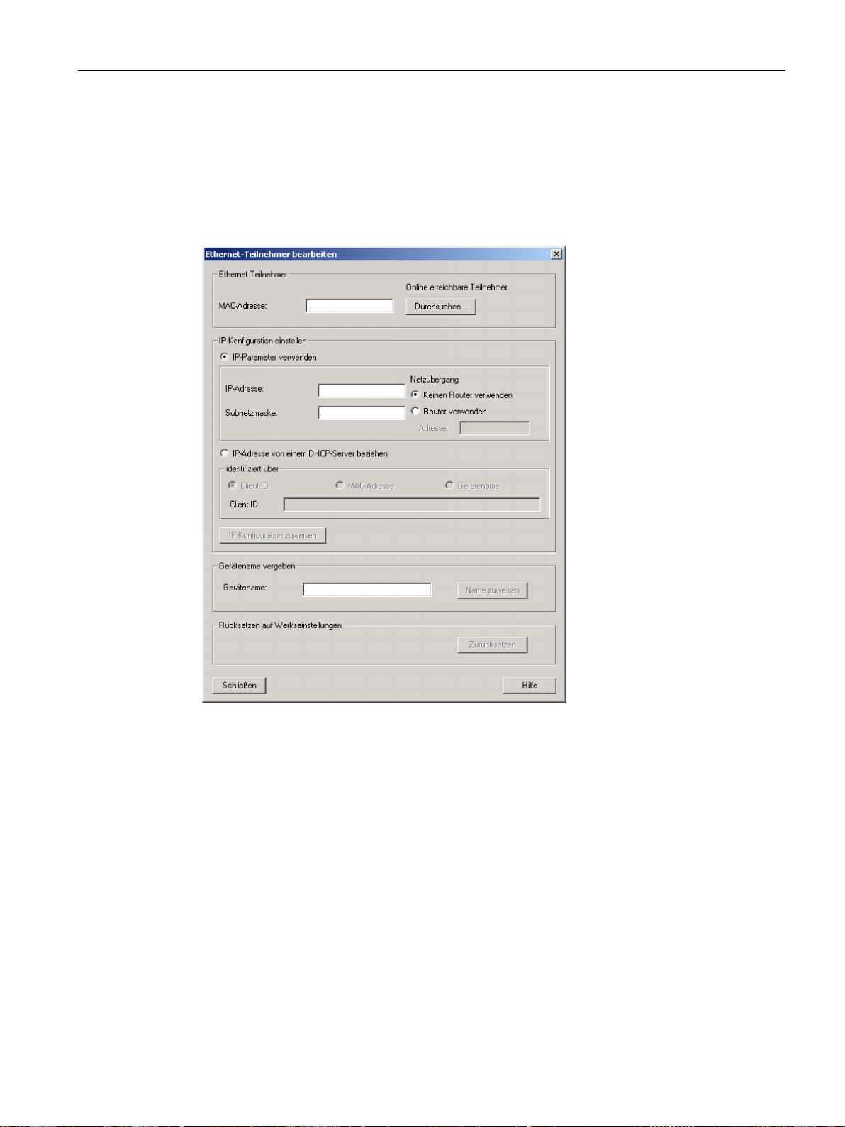
Communication via PROFIBUS and PROFINET
Additional options of integrating inverters into Ethernet
3.6 Communication via PROFINET
You also have the option of integrating the inverter into Ethernet using Proneta or STEP7, for
example.
Here is the example of the "Edit Ethernet station" screen form from Step 7, which you can
use to make the required settings.
Fieldbuses
Function Manual, 04/2018, FW V4.7 SP10, A5E34229197B AE
71
Page 74
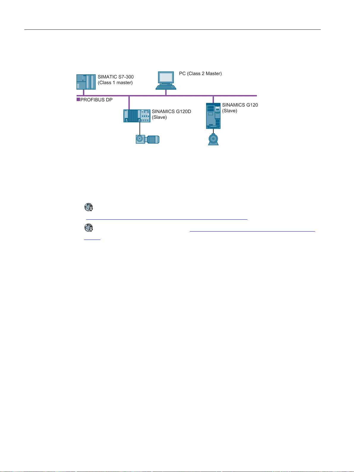
Communication via PROFIBUS and PROFINET
3.7
Communication via PROFIBUS
3.7 Communication via PROFIBUS
The PROFIBUS DP interface has the following functions:
● Cyclic communication
● Acyclic communication
● Diagnostic alarms
General information on PROFIBUS DP can be found in the Internet:
●
● Installation guidelines of the PNO (http://www.profibus.com/downloads/installation-
PROFIBUS information
(https://support.industry.siemens.com/cs/ww/en/view/1971286)
guide/)
Fieldbuses
72 Function Manual, 04/2018, FW V4.7 SP10, A5E34229197B AE
Page 75
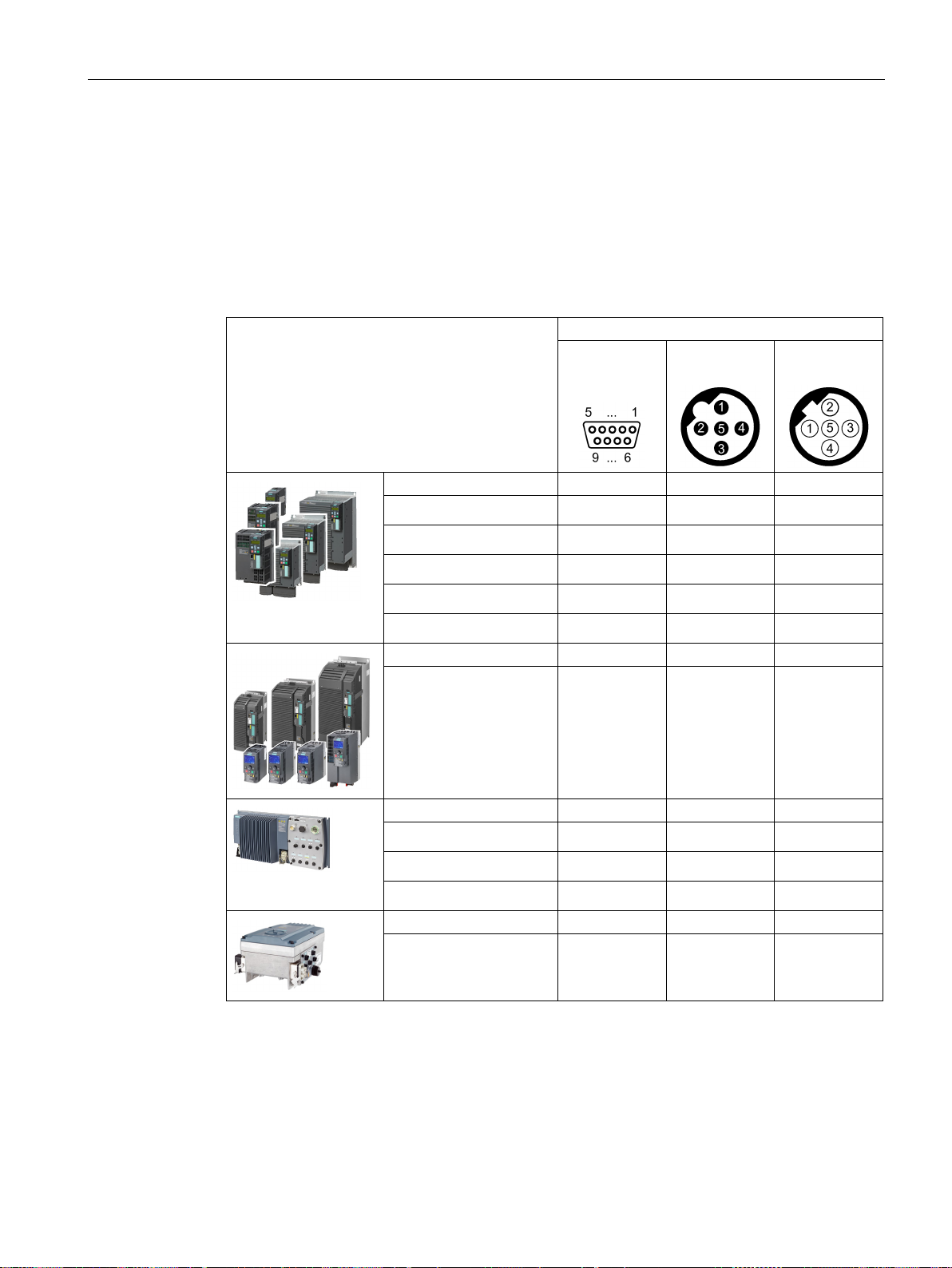
Communication via PROFIBUS and PROFINET
3.7.1
Inverters with PROFIBUS interface
Connection via
G120
G120C
G120D
G110M
3.7 Communication via PROFIBUS
You can find the connectors and the connector assignments of the PROFIBUS DP interface
in the following tables.
You can implement a line-type topology using the two connectors at the inverter. You can
use switches to realize other topologies.
Table 3- 16 Assignment table - connectors
Inverter/Control Unit
X126
(D Sub - sock-
et)
X03, on
(M12)
X04, off
(M12)
• CU230P-2 DP
• CU240B-2 DP
• CU240E-2 DP
• CU240E-2 DP-F
• CU250S-2 DP
• G120C DP
• CU240D-2 DP
• CU240D-2 DP-F
• CU250D-2 DP-F
x
x
x
x
x
x
x x
x x
x x
• CU240M DP
Fieldbuses
Function Manual, 04/2018, FW V4.7 SP10, A5E34229197B AE
x x
73
Page 76
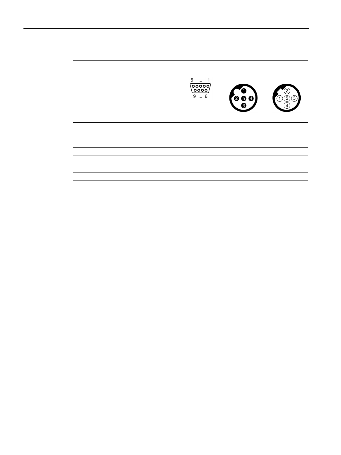
Communication via PROFIBUS and PROFINET
Shield, ground connection
1 5 5
--- 2 1
1
RxD/TxD-P, receive and transmit (B/B’)
3 4 4
CNTR-P, control signal
4
---
---
DGND, reference potential for data (C/C’)
5
---
---
VP, supply voltage
6
---
---
--- 7 3
3
RxD/TxD-N, receive and transmit (A/A’)
8 2 2
--- 9 ---
---
Recommended PROFIBUS connectors
3.7 Communication via PROFIBUS
Table 3- 17 Connector pin assignments
Signal X126
(D Sub - socket)
X03, on
(M12)
X04, off
(M12)
We recommend connectors with the following article numbers for connecting the PROFIBUS
cable:
● 6GK1500-0FC10
● 6GK1500-0EA02
Fieldbuses
74 Function Manual, 04/2018, FW V4.7 SP10, A5E34229197B AE
Page 77
Communication via PROFIBUS and PROFINET
3.7.2
What do you have to set for communication via PROFIBUS?
Configuring PROFIBUS communication
Setting the address
Setting the telegram
Application examples
3.7 Communication via PROFIBUS
You require the appropriate engineering system to configure PROFIBUS communication in
the PROFIBUS master.
If required, load the GSD file of the inverter into the engineering system.
Configuring communication to the control system (Page 76)
Set the address of the PROFIBUS slave.
Setting the address (Page 78)
Set the telegram in the inverter as in the PROFIBUS master. Interconnect the telegrams in
the control program of the PROFIBUS master with the signals of your choosing.
You can find application examples for PROFIBUS communication on the Internet:
via PROFINET or PROFIBUS, with Safety Integrated (via terminal) and HMI
(https://support.industry.siemens.com/cs/ww/en/view/60441457)
PROFINET or PROFIBUS, with Safety Integrated (via terminal) and HMI
(https://support.industry.siemens.com/cs/ww/en/view/78788716)
PROFIDRIVE profile - Cyclic communication (Page 17)
Controlling the speed of a SINAMICS G110M/G120/G120C/G120D with S7-300/400F
Controlling the speed of a SINAMICS G110M / G120 (Startdrive) with S7-1500 (TO) via
Fieldbuses
Function Manual, 04/2018, FW V4.7 SP10, A5E34229197B AE
75
Page 78

Communication via PROFIBUS and PROFINET
3.7.3
Integrating inverters into PROFIBUS
Procedure
3.7.4
Configuring communication to the control system
3.7.4.1
Configuring the communication using SIMATIC S7 control
3.7.4.2
Configuring the communication with a third-party control system
3.7 Communication via PROFIBUS
To connect the inverter to a control system via PROFIBUS DP, proceed as follows:
1. Integrate the inverter into the bus system (e.g. line-type topology) using PROFIBUS
cables.
– Inverters with IP20 degree of protection: via socket X126
– Inverters with degree of protection IP65 (CU240D/CU250D) via X03 and X04
The position of the socket is explained in the operating instructions for the inverter.
Pin assignment:
The maximum permitted cable length to the previous station and the subsequent one is
100 m at a baud rate of 12 Mbit/s. You can achieve a maximum cable length of 400 m by
using a maximum of 3 repeaters.
2. Externally supply the inverter with 24 V DC through terminals 31 and 32 or via X01.
The external 24 V supply is only required if communications with the control system
should also operate when the line voltage is switched off.
You have now connected the inverter to the control system using PROFIBUS DP.
❒
Configure the communication in the control system after you have connected the inverter to
the bus.
● If the inverter is listed in the component catalog in the TIA Portal, you can configure the
communication in the SIMATIC control.
● If the inverter is not listed in the hardware library, you can either install the newest
Startdrive version or install the GSD of the inverter via "Extras/GSD-Install file" in HWConfig.
Inverters with PROFIBUS interface (Page 73).
Fieldbuses
76 Function Manual, 04/2018, FW V4.7 SP10, A5E34229197B AE
If you are working with a third-party control system, you must install the device file (GSD) of
the inverter in the control before you configure the communication.
Installing the GSD (Page 77) .
If you have installed the GSD, configure the communication. To do this, follow the
documentation of your control system.
Page 79

Communication via PROFIBUS and PROFINET
3.7.4.3
Installing the GSD
Procedure
3.7 Communication via PROFIBUS
1. Save the GSD on your PC via one of the following methods.
– With Internet access:
GSD (http://support.automation.siemens.com/WW/view/en/22339653/133100)
– Without Internet access:
Insert a memory card into the inverter.
Set p0804 to 12.
The inverter writes the GSD as zipped file (*.zip) into directory
/SIEMENS/SINAMICS/DATA/CFG on the memory card.
2. Unzip the GSD file on your computer.
3. Import the GSD in the engineering system of the controller.
You have now installed the GSD file in the engineering system of the controller.
❒
Fieldbuses
Function Manual, 04/2018, FW V4.7 SP10, A5E34229197B AE
77
Page 80
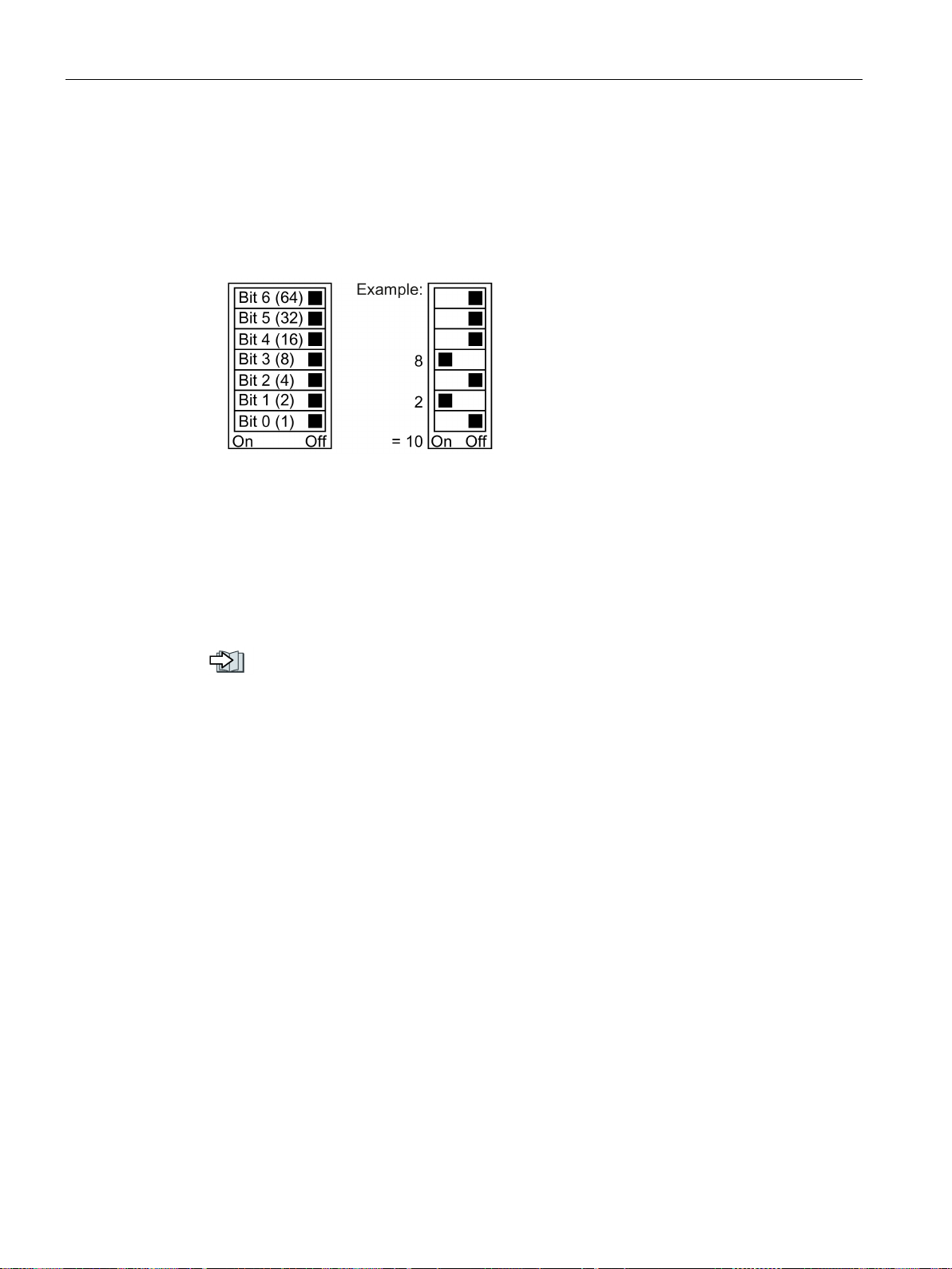
Communication via PROFIBUS and PROFINET
3.7.5
Setting the address
Valid address area: 1 … 125
Activating the changed bus address
Procedure
3.7 Communication via PROFIBUS
You have the following options for setting the address:
● Using the address switch on the Control Unit:
Figure 3-22 Address switch with example for bus address 10
The address switch has priority over the other settings.
● Using Startdrive or an operator panel via parameter p0918 (default setting: p0918 = 126)
It is only possible to change p0918 if an invalid address is set in the address switch.
If you are working with Startdrive, back up the settings so they are not lost if the power
fails.
You can find the position of the address switch in the operating instructions for the inverter.
Manuals and technical support (Page 232)
1. Set the address as described above.
2. Switch off the inverter power supply.
3. Wait until all LEDs on the inverter are dark.
4. Switch on the inverter power supply again.
Your settings become effective after switching on.
You have now set the bus address.
❒
Fieldbuses
78 Function Manual, 04/2018, FW V4.7 SP10, A5E34229197B AE
Page 81

Communication via PROFIBUS and PROFINET
3.8
Select telegram
Precondition
Telegrams for SINAMICS G120 inverters
Value p0922
1:
Standard telegram 1, PZD
2:
Standard telegramm 2, PZD-4/4
3:
Standard telegram 3, PZD-5/9
4:
Standard telegram 4, PZD-6/14
7:
Standard telegram 7, PZD 2/2 (factory setting CU250D)
9:
Standard telegram 9, PZD
20:
Standard telegram 20, PZD-2/6
110:
SIEMENS telegram 110, PZD-12/7
112:
SIEMENS telegram 111, PZD-12/12
350:
SIEMENS telegram 350, PZD-4/4
352:
SIEMENS telegram 352, PZD-6/6
353:
SIEMENS telegram 353, PZD-2/2, PKW-4/4
354:
SIEMENS telegram 354, PZD-6/6, PKW-4/4
999:
Free telegram
(factory setting, CU250S)
PROFIsafe telegram selection
3.8 Select telegram
In the basic commissioning you have selected the control using PROFIBUS or PROFINET.
The following table shows all of the telegrams for the G120 inverter.
In your inverter you have a list of telegrams that are available for your particular inverter.
-2/2 (factory setting, exceptions: CU250D and CU250S)
For further information about telegrams:
PROFIDRIVE profile - Cyclic communication (Page 17).
The settings for the PROFIsafe telegram selection are described in the "Safety Integrated"
Function Manual.
-10/5
Extend telegram/change signal interconnection (Page 33)
Fieldbuses
Function Manual, 04/2018, FW V4.7 SP10, A5E34229197B AE
79
Page 82

Communication via PROFIBUS and PROFINET
3.8 Select telegram
Fieldbuses
80 Function Manual, 04/2018, FW V4.7 SP10, A5E34229197B AE
Page 83

4
EtherNet/IP is real-time Ethernet, and is mainly used in automation technology.
You have the following options of integrating SINAMICS G120 inverters into EtherNet/IP:
● You use the SINAMICS profile
● You use the ODVA AC/DC drive profile
● You define the assemblies for the process data using the objects that are supported by
the inverter
Configuring communication via EtherNet/IP (Page 86).
The pin assignment and the connectors that you require for your inverter are listed in the
following tables.
You can implement a line-type topology using the two sockets at the inverter. You only
require one of the two sockets at the beginning and end of a line.
You can use switches to realize other topologies.
Fieldbuses
Function Manual, 04/2018, FW V4.7 SP10, A5E34229197B AE
81
Page 84
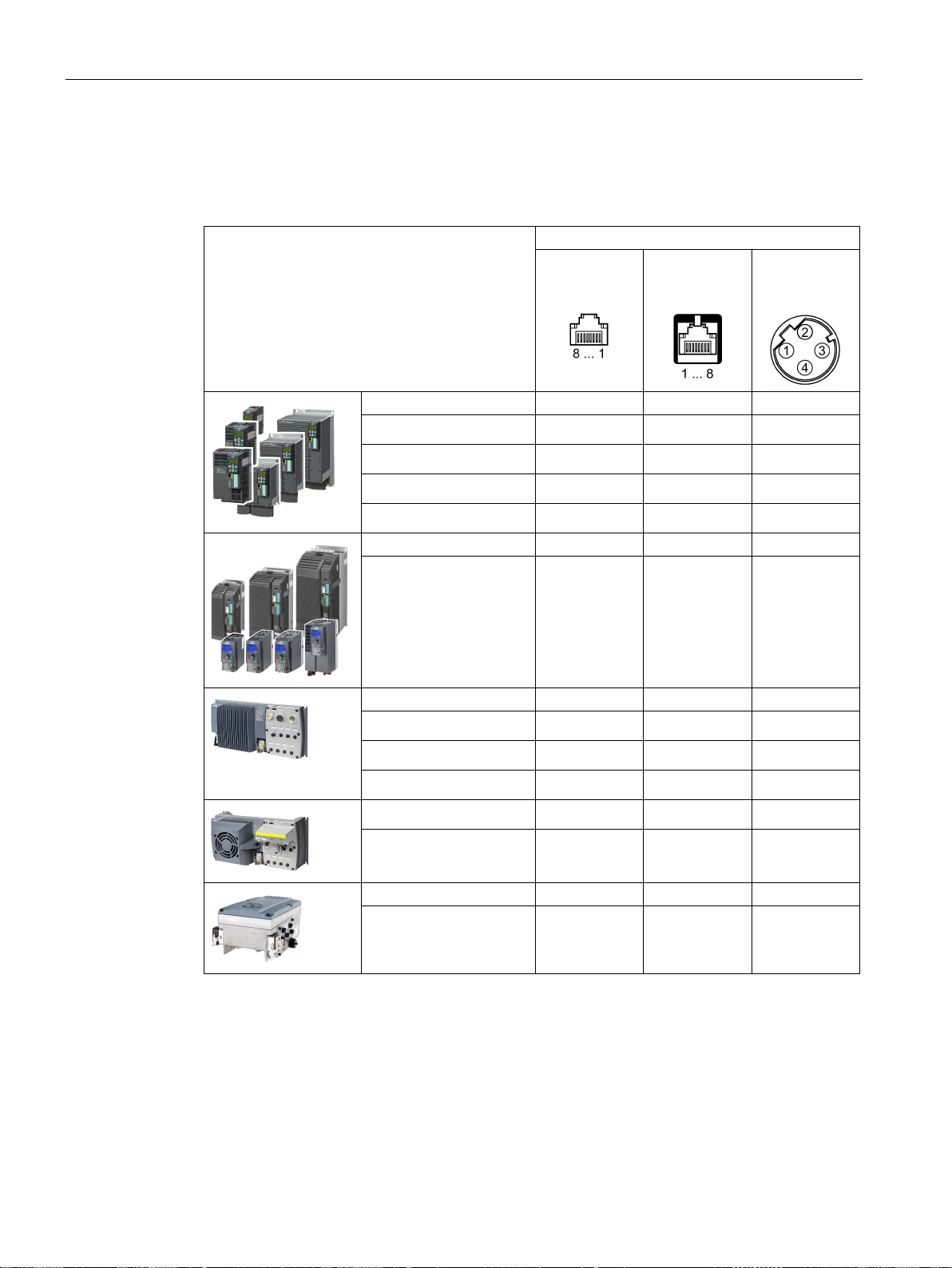
Communication via EtherNet/IP
4.1
Inverters with Ethernet/IP interface
Connection via
G120
G120C
G120D
G110M
4.1 Inverters with Ethernet/IP interface
Table 4- 1 Assignment table
Inverter/Control Unit
X150 P1/
X150 P2
(RJ45)
X03/X04
(RJ45)
X03/X04
(M12)
• CU230P-2 PN
• CU240E-2 PN
• CU240E-2 PN-F
• CU250S-2 PN
• G120C PN
• CU240D-2 PN
• CU240D-2 PN-F
• CU250D-2 PN-F
• CU240D-2 PN-F [PP]
• CU250D-2 PN-F [PP]
x
x
x
x
x
x
x
x
x
x
• CU240M PN
Fieldbuses
x
82 Function Manual, 04/2018, FW V4.7 SP10, A5E34229197B AE
Page 85
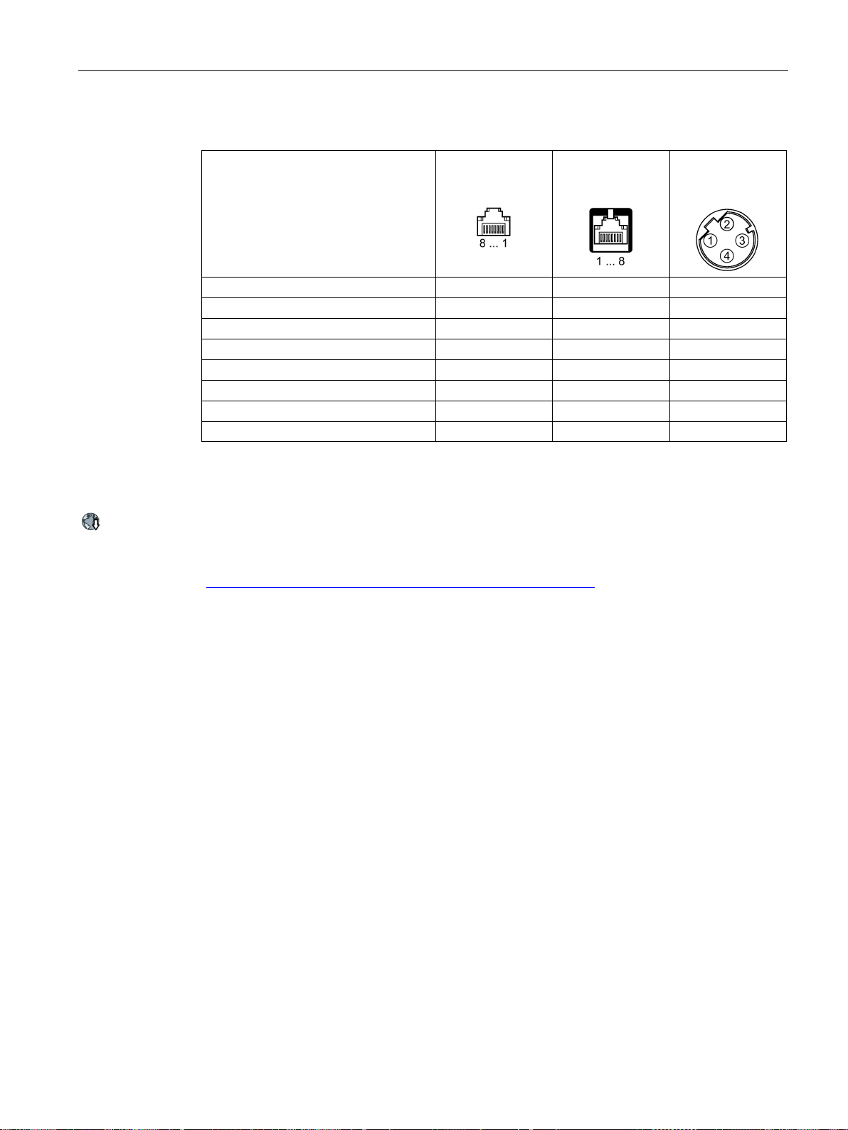
Communication via EtherNet/IP
TX-, transmit data -
1 1 1
RX+, receive data +
3 2 2
TX+ Transmit data +
2 3 3
RX-, receive data -
6 6 4
---
4 4 ---
---
5 5 ---
---
8 8 ---
Recommended connector
4.1 Inverters with Ethernet/IP interface
Table 4- 2 Connector pin assignments
Signal X150 P1/
X150 P2
(RJ45)
--- 7 7 ---
X03/X04
(RJ45)
X03/X04
(M12)
RJ45, IP20: 6GK1901-1BB10-2Ax0
Information for assembling the SIMATIC NET Industrial Ethernet FastConnect RF45 plug
180 can be found on the Internet:
Assembly instructions for the SIMATIC NET Industrial Ethernet FastConnect RJ45 plug
(https://support.industry.siemens.com/cs/ww/en/ps/15251/man)
Fieldbuses
Function Manual, 04/2018, FW V4.7 SP10, A5E34229197B AE
83
Page 86
Communication via EtherNet/IP
4.2
Connect converter to Ethernet/IP
Procedure
Routing and shielding Ethernet cables
Commissioning the inverter in an EtherNet/IP network
4.2 Connect converter to Ethernet/IP
To connect the inverter to a control system via Ethernet, proceed as follows:
1. Connect the inverter to the control system via an Ethernet cable.
2. You create an object for data exchange.
You have the following options:
– Load the EDS file into your controller if you want to use the ODVA profile.
You can find the EDS file in the Internet:
EDS (https://support.industry.siemens.com/cs/ww/de/view/78026217)
– If your controller does not accept the EDS file, or if you wish to use the SINAMICS
profile, you must create a generic module in your controller:
Create generic I/O module (Page 103)
You have connected the inverter to the control system via EtherNet/IP.
❒
In addition, you can find a detailed description of how to connect a SINAMICS G converter to
a controller via Ethernet/IP at the following link:
Application example (https://support.industry.siemens.com/cs/ww/en/view/82843076)
Information can be found on the Internet:
EtherNet/IP
(http://www.odva.org/Home/ODVATECHNOLOGIES/EtherNetIP/EtherNetIPLibrary/tabid/76/l
ng/en-US/Default.aspx)
To commission the inverter, connect the inverter via the USB interface with your computer
on which Startdrive has been installed.
For additional information, refer to the operating instructions of your inverter.
Manuals and technical support (Page 232)
Fieldbuses
84 Function Manual, 04/2018, FW V4.7 SP10, A5E34229197B AE
Page 87

Communication via EtherNet/IP
4.3
What do you need for communication via Ethernet/IP?
4.3 What do you need for communication via Ethernet/IP?
Check the communication settings using the following questions. If you answer "Yes" to the
questions, you have correctly set the communication settings and can control the inverter via
the fieldbus.
● Is the inverter correctly connected to the EtherNet/IP?
● Is the EDS file installed in your control system?
● Have the bus interface and IP address been correctly set?
● Have the signals that the inverter and the control system exchange been correctly
interconnected?
Fieldbuses
Function Manual, 04/2018, FW V4.7 SP10, A5E34229197B AE
85
Page 88

Communication via EtherNet/IP
4.4
Configuring communication via EtherNet/IP
Procedure
4.4.1
Communication settings
Communication via the SINAMICS profile
Communication via the ODVA AC/DC drive profile
Communication settings via EtherNet/IP objects and assemblies
4.4 Configuring communication via EtherNet/IP
Make the following settings in order to communicate with a higher-level control via
EtherNet/IP:
1. p2030: set a value of 10: Fieldbus interface protocol selection Ethernet/IP:
2. p8921: Enter the IP address. You can find the currently valid address in r8931.
3. p8923: Enter the subnet mask. You can find the currently valid subnet mask in r8933.
4. p8922: Enter the standard gateway. You can find the currently valid Default Gateway in
r8932.
5. p8920: Enter the station name.
6. p8925: Set a value of 2: Save and activate PN interface configuration
7. Switch off the inverter power supply.
8. Wait until all LEDs on the inverter are dark.
9. Switch on the inverter power supply again.
Your settings become effective after switching on.
You have now configured the inverter for communication via EtherNet/IP.
❒
Parameters p8921 … p8925 apply if p2030 = 10 is set, for EtherNet/IP, even if the
parameter names indicates PROFINET.
You set the communication using parameter p8980. You have the following options
The SINAMICS profile is a drive profile for EtherNet/IP defined by Siemens, based on
PROFIdrive, and is factory set in the inverters.
Setting: p8980 = 0
With the SINAMICS profile, you can use each of the telegrams listed in parameter p0922
The ODVA AC/DC drive profile is a drive profile defined by the ODVA organization
Setting: p8980 = 1
With the AC/DC profile of ODVA, you select the standard telegram, p0922 = 1
If you are using assemblies, which are described in the "Supported objects" (
Supported objects (Page 88)), then you must integrate the inverter yourself into the control
system. Details on this topic can be found in the documentation of your control system.
Fieldbuses
86 Function Manual, 04/2018, FW V4.7 SP10, A5E34229197B AE
Page 89

Communication via EtherNet/IP
4.4.2
Special issues if you wish to use the ODVA AC/DC Drive profile
Setting the off response for the motor
Setting the speed and torque scaling
Displaying the maximum process data that can be transferred (PZD)
Switching over the master control from the controller to Startdrive
4.4 Configuring communication via EtherNet/IP
If you change the following parameters using Startdrive or an operator panel, you must
switch off the inverter power supply and switch it on again in order for the changes to
become effective.
You set the standard off response for the inverter using parameter p8981:
● p8981 = 0: OFF1 (factory setting), also corresponds to the setting in the SINAMICS
profile
● p8981 = 1: OFF2
You can find details about OFF1 and OFF2 in the operating instructions of the Control Unit in
the Section "Switching on and switching off a motor".
You scale the speed and torque display using parameter p8982 or p8983. Setting range: 25
-5
.
to 2
● r2067[0] maximum interconnected PZD length - receiving
● r2067[1] maximum interconnected PZD length - sending
In order to retrieve the master control using Startdrive, you must either switch the CPU to
STOP, or interrupt the connection to the controller.
Fieldbuses
Function Manual, 04/2018, FW V4.7 SP10, A5E34229197B AE
87
Page 90
Communication via EtherNet/IP
4.5
Supported objects
Overview
Object class
Object name
Objects re-
quired
ODVA objects
SINAMICS
objects
hex
dec
1 hex
1
Identity object
x
4 hex
4
Assembly Object
x
28 hex
40
Motor Data Object
x
29 hex
41
Supervisor Object
x
2A hex
42
Drive Object
x
32C hex
812
Siemens Drive Object
x
32D hex
813
Siemens Motor Data Object
x F5 hex
245
TCP/IP Interface Object 1)
x
F6 hex
246
Ethernet Link Object 1)
x
300 hex
768
Stack Diagnostic Object
x
x
302 hex
770
Adapter Diagnostic Object
x x 303 hex
771
Explicit Messages Diagnostic Object
x
x
304 hex
772
Explicit Message Diagnostic List Object
x
x
401 hex
1025
Parameter object
x
x
1)
These objects are part of the EtherNet/IP system management.
Identity Object, Instance Number: 1 hex
Supported services
Class
•
•
Instance
•
•
•
No.
Service
Type
Name
1
get
UINT16
Revision
2
get
UINT16
Max Instance
3
get
UINT16
Num of Instances
4.5 Supported objects
6 hex 6 Connection Management Object x
Get Attribute all
Get Attribute single
Table 4- 3 Class Attribute
Get Attribute all
Get Attribute single
Reset
Fieldbuses
88 Function Manual, 04/2018, FW V4.7 SP10, A5E34229197B AE
Page 91

Communication via EtherNet/IP
No.
Service
Type
Name
Value/explanation
1
get
UINT16
Vendor ID
1251
3
get
UINT16
Product code
r0964[1]
4
get
UINT16
Revision
The versions should match the EDS file
5
get
UINT16
Status
See the following table
Bits 28 … 31: Year of manufacture (0 = 2002)
String
e.g. SINAMICS G120
Byte
Bit
Name
Description
1: Inverter is assigned to a master
1 Reserved
For G120, always = 1
3 Reserved
8 … 15: Reserved
8 … 11
Not used
12 … 15
Reserved
4.5 Supported objects
Table 4- 4 Instance Attribute
2 get UINT16 Device Type
- ODVA AC Drive
- Siemens Drive
02 hex
12 hex
6 get UINT32 Serial number bits 0 … 19: consecutive number;
bits 20 … 23: Production identifier
bits 24 … 27: Month of manufacture (0 = Jan, B =
Dec)
7 get Short
Product name max. length 32 bytes
Table 4- 5 Explanation of No. 5 of the previous table
1 0 Owned 0: Inverter is not assigned to any master
2 Configured 0: Ethernet/IP basic settings
1: Modified Ethernet/IP settings
4 … 7 Extended De-
vice Status
2
Fieldbuses
Function Manual, 04/2018, FW V4.7 SP10, A5E34229197B AE
0: Self-test or status not known
1: Firmware update active
2: At least one I/O connection with error
3: No I/O connections
4: Incorrect configuration in the ROM
5: Fatal fault
6: At least one I/O connection is active
7: All I/O connections in the quiescent state
89
Page 92
Communication via EtherNet/IP
Assembly Object, Instance Number: 4 hex
Supported services
Class
•
Instance
•
•
No.
Service
Type
Name
1
get
UINT16
Revision
2
get
UINT16
Max Instance
3
get
UINT16
Num of Instances
No.
Service
Type
Name
Value/explanation
4.5 Supported objects
Get Attribute single
Get Attribute single
Set Attribute single
Table 4- 6 Class Attribute
Table 4- 7 Instance Attribute
3 get Array of
UINT8
Assembly
1 byte array
Supported ODVA AC/DC assemblies
(Page 102)
Fieldbuses
90 Function Manual, 04/2018, FW V4.7 SP10, A5E34229197B AE
Page 93
Communication via EtherNet/IP
Connection Management Object, Instance Number: 6 hex
Supported services
Class
•
•
Instance
•
•
•
•
No.
Service
Type
Name
1
get
UINT16
Revision
2
get
UINT16
Max Instance
3
get
UINT16
Num of Instances
No.
Service
Type
Name
Value/explanation
1
get
UINT16
OpenReqs
Counters
Rejects
Rejects
jects
5
get
UINT16
CloseReqs
Counters
Rejects
jects
Number of bus errors
4.5 Supported objects
Get Attribute all
Get Attribute single
Forward open
Forward close
Get Attribute single
Set Attribute single
Table 4- 8 Class Attribute
Table 4- 9 Instance Attribute
2 get UINT16 OpenFormat
3 get UINT16 OpenResource
4 get UINT16 OpenOther Re-
Counters
Counters
Counters
Fieldbuses
Function Manual, 04/2018, FW V4.7 SP10, A5E34229197B AE
6 get UINT16 CloseFormat
7 get UINT16 CloseOther Re-
8 get UINT16 ConnTimeouts Counters
Counters
Counters
91
Page 94
Communication via EtherNet/IP
Motor Data Object, Instance Number 28 hex
Supported services
Class
•
Instance
•
•
No. Ser-
vice
Type
Name
1
get
UINT16
Revision
2
get
UINT16
Max Instance
3
get
UINT16
Num of Instances
No. Service
Type
Name
Value/explanation
3
get, set
USINT
Motor Type
p0300 motor type, see the following table
6
get, set
UINT16
Rated Current
p0305 rated motor current
7
get, set
UINT16
Rated Voltage
p0304 rated motor voltage
8
get, set
UINT32
Rated Power
p0307 rated motor power
9
get, set
UINT16
Rated Frequency
p0310 rated motor frequency
ture
11
get, set
UINT16
Max Speed
p0322 maximum motor speed
12
get, set
UINT16
Pole Count
p0314 value of p0314*2
14
get, set
UINT32
Inertia
p0341 motor moment of inertia
15
get, set
UINT16
Base Speed
p0311 motor rated speed
Value in p0300
Ethernet/IP motor data object,
4.5 Supported objects
Get Attribute single
Table 4- 10 Class Attribute
Table 4- 11 Instance Attribute
10 get, set UINT16 Rated Tempera-
Get Attribute single
Set Attribute single
p0605 motor temperature threshold
13 get, set UINT32 Torque Constant p0316 motor torque constant
10
13
17
19
Fieldbuses
92 Function Manual, 04/2018, FW V4.7 SP10, A5E34229197B AE
100
104
107
108
200
204
237
10000
10001
0
No motor
1
induction motor
2
synchronous motor
1LE1 induction motor
1LG6 induction motor
1LA7 induction motor
1LA9 induction motor
1LE1 induction motor
1PH4 induction motor
1PH7 induction motor
1PH8 induction motor
1PH8 synchronous motor
1LE4 synchronous motor
1FK7 synchronous motor
motor with DRIVE-CLiQ
motor with DRIVE-CLiQ 2. D
0
Non-standard motor
7
squirrel cage induction motor
3
PM synchronous motor
7
squirrel cage induction motor
7
squirrel cage induction motor
7
squirrel cage induction motor
7
squirrel cage induction motor
7
squirrel cage induction motor
3
PM synchronous motor
0
non-standard motor
5
switched reluctance motor
0
non-standard motor
3
PM synchronous motor
0
non-standard motor
0
non-standard motor
0
non-standard motor
Page 95
Communication via EtherNet/IP
Supervisor Object, Instance Number: 29 hex
Supported services
Class
•
Instance
•
•
No. Ser-
vice
Type
Name
1
get
UINT16
Revision
2
get
UINT16
Max Instance
3
get
UINT16
Num of Instances
No. Ser-
vice
Type
Name
Value/explanation
3
get, set
Bool
Run1
STW.0 operation, clockwise rotation
1: Network
0 = Other state
0 = Other state
10
get
Bool
Fault
ZSW1:3 drive fault
11
get
Bool
Warning
ZSW1:7 alarm active
12
get, set
Bool
Fault reset
STW.7 acknowledge fault
13
get
UINT16
Fault Code
r945[0] error code
0: Local control
4.5 Supported objects
Get Attribute single
Get Attribute single
Set Attribute single
Table 4- 12 Class Attribute
Table 4- 13 Instance Attribute
5 get, set Bool Net Control Internal
0: Local
6 get UINT8 State 0: Vendor Specific
1: Startup
2: Not_Ready
3: Ready
4: Enabled
5: Stopping
6: Fault_Stop
7: Faulted
7 get Bool Running1 ZSW1:2
1: - (Enabled and Run1) or
- (Stopping and Running1) or
- (Fault_Stop and Running1)
Fieldbuses
Function Manual, 04/2018, FW V4.7 SP10, A5E34229197B AE
9 get Bool Ready ZSW1:0
1: - Ready or
- Enabled or
- Stopping
14 get UINT16 Warning Code r2122[0] alarm code
15 get Bool CtlFromNet Display from Net Control
1: Control from network
93
Page 96
Communication via EtherNet/IP
Drive Object, Instance Number: 2A hex
Supported services
Class
•
Instance
•
•
No. Ser-
vice
Type
Name
1
get
UINT16
Revision
2
get
UINT16
Max Instance
3
get
UINT16
Num of Instances
No. Ser-
vice
Type
Name
Value/explanation
0: Otherwise
1: Network
6
get
UINT8
Drive_Mode
p1300 manufacturer-specific, see following table
7
get
INT
Speed Actual
Main actual value, see speed units
9
get
INT
Current Actual
r0027 absolute current actual value, smoothed
10
get, set
INT
Current limit
p0323 maximum motor current
15
get
INT
Power Actual
r0032 actual active power smoothed
16
get
INT
Input voltage
r0025 output voltage smoothed
17
get
INT
Output voltage
r0072 output voltage
18
get, set
UINT16
AccelTime
p1120 ramp-function generator ramp-up time
19
get, set
UINT16
DecelTime
p1121 ramp-function generator, ramp-down time
20
get, set
UINT16
Low Speed Lim
p1080 minimum speed
21
get, set
UINT16
High Speed Lim
p1082 maximum speed
22
get, set
SINT
Speed Scale
p8982 Ethernet/IP ODVA speed scaling
1: Network
4.5 Supported objects
Get Attribute single
Get Attribute single
Set Attribute single
Table 4- 14 Class Attribute
Table 4- 15 Instance Attribute
3 get Bool At reference r2197.4
1: |n_act | ≥ n_set
4 get, set Bool Net_reference Internal
0: Local
8 get, set INT Speed Ref Main setpoint, see speed units
29 get Bool Ref From Net Internal - display of Net_Reference
0: Local
Fieldbuses
94 Function Manual, 04/2018, FW V4.7 SP10, A5E34229197B AE
Page 97
Communication via EtherNet/IP
Value in p1300
Ethernet/IP motor data object
22
Closed-torque control (without encoder)
3
Torque control
Siemens Drive Object, Instance Number: 32C hex
Supported services
Class
•
Instance
•
•
No.
Service
Type
Name
2
get
UINT16
Max Instance
No.
Service
Name
Value/explanation
2
get, set
Commissioning state
p0010 commissioning parameter filter
Attr.18 = STW1.15
19
get
Main setpoint
Main setpoint
Attr.35 = ZSW1.15
36
get
Actual Frequency
Main actual value (actual frequency)
ramp-up time
ramp-down time
39
get, set
Current Limit
p0640[0] current limit
40
get, set
Frequency MAX Limit
p1082[0] maximum speed
41
get, set
Frequency MIN Limit
p1080[0] minimum speed
43
get, set
PID Enable
p2200[0] technology controller enable
4.5 Supported objects
0
U/f with linear characteristics
1
U/f with linear characteristics and FCC
2
U/f with parabolic characteristics
3
U/f with parameterizable characteristics
4
U/f with linear characteristics and ECO
5
U/f for precise frequency drive (textile sector)
6
U/f for precise frequency drive and FCC
7
U/f for parabolic characteristics and ECO
19
U/f with independent voltage setpoint
20
Closed-loop speed control (without encoder)
1
Open loop speed (Frequency)
0
Vendor specific mode
0
Vendor specific mode
0
Vendor specific mode
0
Vendor specific mode
0
Vendor specific mode
0
Vendor specific mode
0
Vendor specific mode
0
Vendor specific mode
2
Closed loop speed control
Get Attribute single
Get Attribute single
Set Attribute single
Table 4- 16 Class Attribute
1 get UINT16 Revision
3 get UINT16 Num of Instances
Table 4- 17 Instance Attribute
3 … 18 get STW1 STW1 bit-by-bit access:
Attr.3 = STW1.0
20 … 35 get ZSW1 ZSW1 bit-by-bit access:
Attr.20 = ZSW1.0
37 get, set Ramp Up Time p1120[0] ramp-function generator
Fieldbuses
Function Manual, 04/2018, FW V4.7 SP10, A5E34229197B AE
38 get, set Ramp Down Time p1121[0] ramp-function generator
42 get, set OFF3 Ramp Down
Time
p1135[0] OFF3 ramp-down time
95
Page 98

Communication via EtherNet/IP
No.
Service
Name
Value/explanation
stant
value filter time constant
tional gain
time
mum limiting
limiting
50
get
Speed setpoint
r0020 speed setpoint
51
get
Output Frequency
r0024 output frequency
52
get
Output Voltage
r0025 output voltage
53
get
DC Link Voltage
r0026[0] DC link voltage
54
get
Actual Current
r0027 current actual value
55
get
Actual Torque
r0031 torque actual value
56
get
Output power
r0032 actual active power value
57
get
Motor Temperature
r0035[0] motor temperature
ture
59
get
Energy kWh
r0039 energy display
61
get
Status Word 2
r0053 status word 2
62
get
Control Word 1
r0054 control word 1
63
get
Motor Speed (Encoder)
r0061 speed actual value
64
get
Digital Inputs
r0722 digital inputs status
65
get
Digital Outputs
r0747 digital outputs status
66
get
Analog Input 1
r0752[0] analog input 1
67
get
Analog Input 2
r0752[1] analog input 2
68
get
Analog Output 1
r0774[0] analog output 1
69
get
Analog Output 2
r0774[1] analog output 2
70
get
Fault Code 1
r0947[0] fault number 1
71
get
Fault Code 2
r0947[1] fault number 2
72
get
Fault Code 3
r0947[2] fault number 3
73
get
Fault Code 4
r0947[3] fault number 4
74
get
Fault Code 5
r0947[4] fault number 5
75
get
Fault Code 6
r0947[5] fault number 6
76
get
Fault Code 7
r0947[6] fault number 7
77
get
Fault Code 8
r0947[7] fault number 8
78
get
Pulse Frequency
r1801 pulse frequency
80
get
Alarm Code 2
r2110[1] alarm number 2
4.5 Supported objects
44 get, set PID Filter Time Con-
45 get, set PID D Gain p2274 technology controller differen-
46 get, set PID P Gain p2280 technology controller propor-
47 get, set PID I Gain p2285 technology controller integral
48 get, set PID Up Limit p2291 technology controller maxi-
49 get, set PID Down Limit p2292 technology controller minimum
58 get Power Unit Tempera-
p2265 technology controller actual
tiation time constant
r0037[0] power unit temperature
60 get CDS Eff (Local Mode) r0050 active command data set
79 get Alarm Code 1 r2110[0] alarm number 1
Fieldbuses
96 Function Manual, 04/2018, FW V4.7 SP10, A5E34229197B AE
Page 99
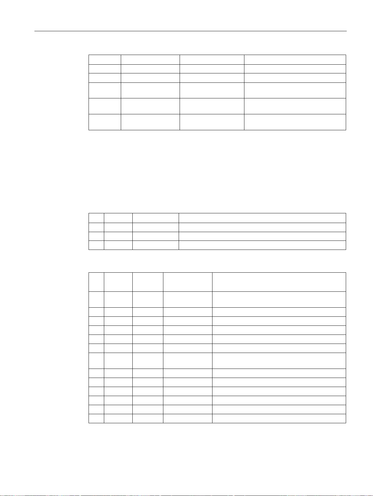
Communication via EtherNet/IP
No.
Service
Name
Value/explanation
81
get
Alarm Code 3
r2110[2] alarm number 3
after the ramp-function generator
value after the filter
signal
Siemens Motor Data Object, Instance Number: 32D hex
Supported services
Class
•
Instance
•
•
No.
Service
Type
Name
2
get
UINT16
Max Instance
3
get
UINT16
Num of Instances
No. Service
Type
Name
Value/explanation
state
3
get
INT16
Motor Type
p0300
6
get, set
REAL
Rated Current
p0305
7
get, set
REAL
Rated Voltage
p0304
8
get, set
REAL
Rated Power
p0307
9
get, set
REAL
Rated Frequency
p0310
ture
11
get, set
REAL
Max Speed
p0322
12
get, set
UINT16
Pole pair number
p0314
13
get, set
REAL
Torque Constant
p0316
14
get, set
REAL
Inertia
p0341
15
get, set
REAL
Base Speed
p0311
19
get, set
REAL
Cos Phi
p0308
4.5 Supported objects
82 get Alarm Code 4 r2110[3] alarm number 4
83 get PID setpoint Output r2260 technology controller setpoint
84 get PID Feedback r2266 technology controller actual
85 get PID Output r2294 technology controller output
Get Attribute single
Table 4- 18 Class Attribute
1 get UINT16 Revision
Table 4- 19 Instance Attribute
2 get, set UINT16 Commissioning
p0010
Get Attribute single
Set Attribute single
Fieldbuses
Function Manual, 04/2018, FW V4.7 SP10, A5E34229197B AE
10 get, set REAL Rated Tempera-
p0605
97
Page 100
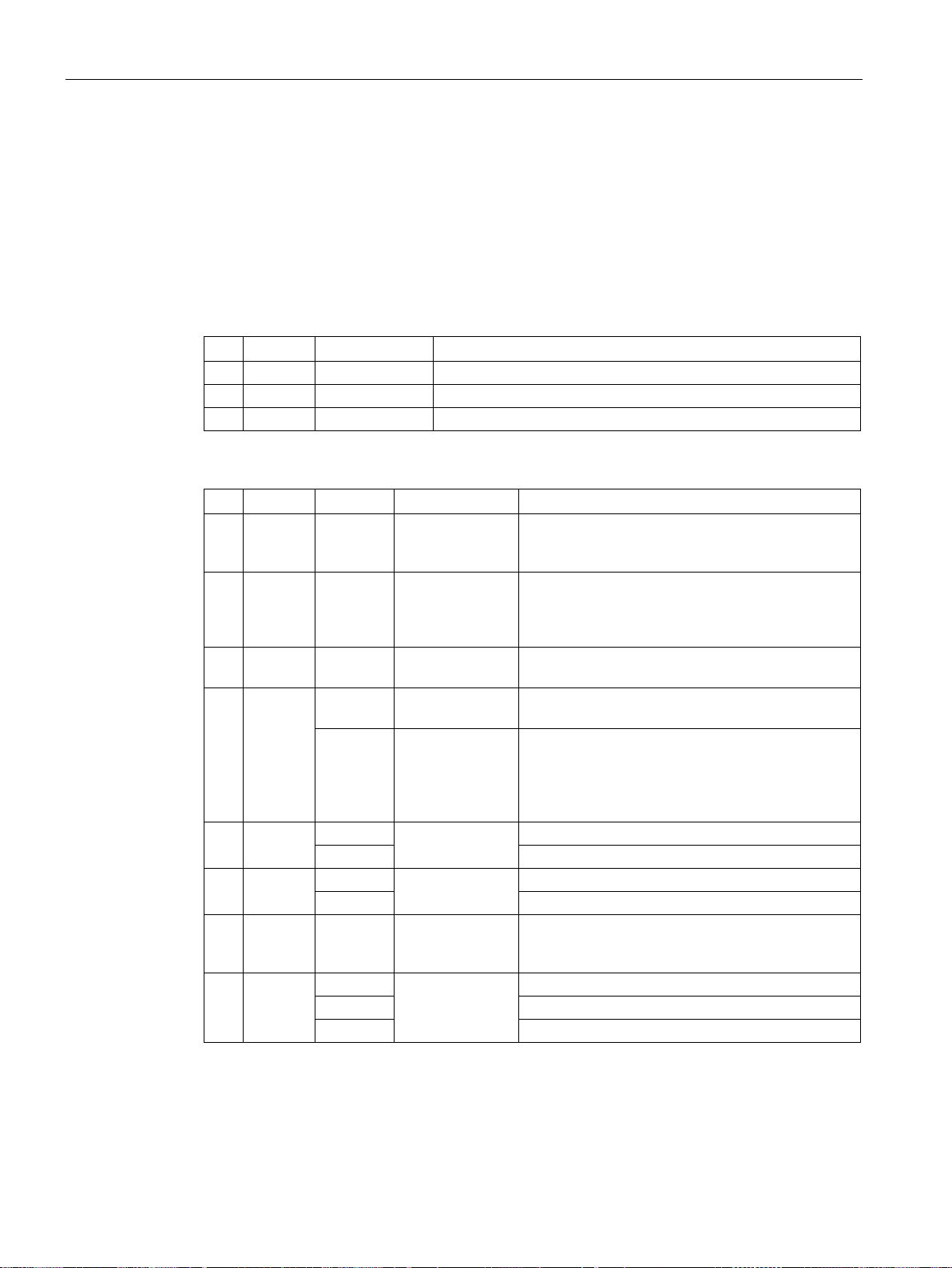
Communication via EtherNet/IP
TCP/IP Interface Object, Instance Number: F5 hex
Supported services
Class
•
•
Instance
•
•
•
No.
Service
Type
Name
1
get
UINT16
Revision
2
get
UINT16
Max Instance
3
get
UINT16
Num of Instances
No.
Service
Type
Name
Value/explanation
Configuration acknowledged, by DHCP or saved
values
80 hex: ACD-capable
WORDs)
F6 hex (four physical ports plus one internal port).
STRING
r61000 Name of Station
UNIT32
r61001 IP address
UNIT16
Host Name Length
STRING
1: Enabled
UNIT8
local OM flash ACD Activity
UNIT8
local OM flash Remote MAC
UNIT8
local OM flash ARP PDU
4.5 Supported objects
Get Attribute all
Get Attribute single
Table 4- 20 Class Attribute
Table 4- 21 Instance Attribute
1 get UNIT32 Status Fixed value: 1 hex
1:
2 get UNIT32 Configuration
Capability
3 get, set UNIT32 Configuration
Control
4 get UNIT16 Path Size (in
Fixed value: 94 hex
4 hex: DHCP supported,
10 hex: Configuration can be adjusted,
1 hex: Saved values
3 hex: DHCP
Fixed value: 2 hex
Get Attribute all
Get Attribute single
Set Attribute single
5 get, set
6 get, set
10 get, set UNIT8 Select ACD local OM flash:
11 get, set
Fieldbuses
98 Function Manual, 04/2018, FW V4.7 SP10, A5E34229197B AE
UNIT8 Path 20 hex,
F6 hex,
24 hex,
05 hex, where 5 hex is the number of instances of
Interface Configuration
Host Name
0: Disabled,
Last Conflict
Detected
 Loading...