


Siemens SINUMERIK 840, SINUMERIK 880 GA2 T/M, SINUMERIK 840C, SINUMERIK 880, SINUMERIK 880 GA2 Planning Manual
...
SINUMERIK 840/840C
SINUMERIK 880/880 GA2
Computer Link
General Description
Planning Guide 09.95 Edition
Manufacturer Documentation

SINUMERIK 840/840C
SINUMERIK 880/880 GA2
Computer Link
General Description
Planning Guide
Manufacturer Documentation
Valid for:
Control Software version
SINUMERIK 840 from 1
SINUMERIK 840C from 1
SINUMERIK 880 T/M from 3
SINUMERIK 880 GA2 T/M from 1
September 1995 Edition

SINUMERIK® documentation
Printing history
Brief details of this edition and previous editions are listed below.
The status of each edition is shown by the code in the ”Remarks” column.
Status code in
”Remarks”
column
:
A . . . New documentation B . . . Unrevised reprint with new Order No.
C . . . Revised edition with new status. If factual changes have been made on the page since
the last edition, this is indicated by a new edition coding in the header on that page.
Edition Order No. Remarks
08.89 6ZB5 410-0CB02-0BA0 A
06.91 6ZB5 410-0CB02-0AA1 C
09.95 6FC5 197-0AB20-0BP0 C
Other functions not described in this documentation might be
executable in the control. This does not, however, represent an
obligation to supply such functions with a new control or when
servicing.
This publication was produced on the Siemens 5800 Office
System.
Subject to change without prior notice.
The reproduction, transmission or use of this document or its
contents is not permitted without express written authority.
Offenders will be liable for damages. All rights, including rights
created by patent grant or registration of a utility model or
design, are reserved.
©
Siemens AG 1989, 1991, 1995 All Rights Reserved
Preliminary Remarks
aaaaa
a
aaaaa
a
aaaaa
a
aaaaa
a
aaaaa
a
aaaaa
a
aaaaa
a
aaaaa
a
aaaaa
a
aaaaa
a
aaaaa
a
aaaaa
a
aaaaa
a
aaaaa
a
aaaaa
a
aaaaa
a
aaaaa
a
aaaaa
a
aaaaa
a
aaaaa
a
aaaaa
a
aaaaa
a
aaaaa
a
aaaaa
a
aaaaa
a
aaa
a
aaa
a
aaa
a
aaa
a
aaa
a
aaa
a
aaa
a
aaa
a
aaa
a
aaa
a
aaa
a
aaa
a
aaa
a
aaaaa
a
aaaaa
a
aaaaa
a
aaaaa
a
aaaaa
a
aaaaa
a
aaaaa
a
aaaaa
a
aaaaa
a
aaaaa
a
aaaaa
a
aaaaa
a
aaaaa
a
aaaaa
a
aaaaa
a
aaaaa
a
aaaaa
a
aaaaa
a
aaaaa
a
aaaaa
a
aaaaa
a
aaaaa
a
aaaaa
a
aaaaa
a
aaaaa
a
aaa
a
aaa
a
aaa
a
aaa
a
aaa
a
aaa
a
aaa
a
aaa
a
aaa
a
aaa
a
aaa
a
aaa
a
aaa
a
Reader guidance
This documentation is intended for manufacturers and users who wish to obtain information on
the computer link with SINUMERIK 840/880.
The description provides a general overview of the computer link, focussing on the computer
link with SINUMERIK 840/880.
It is meant as a first introduction for users who are not yet familiar with the computer link with
SINUMERIK 880 as it describes the basics for the message frame traffic. The manual
"SINUMERIK 840/880 Computer Link General Description" is part of a documentation set on
the 840/880 computer link that is organized as follows:
• General documentation
• Configuration documentation
• Installation and service documentation
The term ”SINUMERIK 8X0” is used in this description as a short form for
”SINUMERIK 840/880”.
Technical information
This documentation applies to software version 1 and higher in the case
of SINUMERIK 840 and 840C to software version 3 and higher in the case
of SINUMERIK 880 GA2 to software version 1.

General 1
Local Area Networks 2
Interface Modules 3
COM 4
PLC 5
Message Frames 6
Configuration and Test 7
Abbreviations 8
Appendix 9

Contents
Page
1 General . . . . . . . . . . . . . . . . . . . . . . . . . . . . . . . . . . . . . . . . . . . . . 1–1
1.1 Definition of terms . . . . . . . . . . . . . . . . . . . . . . . . . . . . . . . . . . . . . . 1–2
1.1.1 Computer link . . . . . . . . . . . . . . . . . . . . . . . . . . . . . . . . . . . . . . . . . 1–2
1.1.2 ISO reference model . . . . . . . . . . . . . . . . . . . . . . . . . . . . . . . . . . . . 1–3
1.1.3 LAN . . . . . . . . . . . . . . . . . . . . . . . . . . . . . . . . . . . . . . . . . . . . . . . . 1–4
1.1.4 MAP . . . . . . . . . . . . . . . . . . . . . . . . . . . . . . . . . . . . . . . . . . . . . . . . 1–4
1.1.5 SINEC AP 1 . . . . . . . . . . . . . . . . . . . . . . . . . . . . . . . . . . . . . . . . . . . 1–4
1.1.6 Transport connection TPV . . . . . . . . . . . . . . . . . . . . . . . . . . . . . . . . . 1–5
1.1.7 Logical peer . . . . . . . . . . . . . . . . . . . . . . . . . . . . . . . . . . . . . . . . . . . 1–6
2 Local Area Networks . . . . . . . . . . . . . . . . . . . . . . . . . . . . . . . . . . . 2–1
2.1 Bus connection . . . . . . . . . . . . . . . . . . . . . . . . . . . . . . . . . . . . . . . . 2–1
2.1.1 The ISO seven layer model . . . . . . . . . . . . . . . . . . . . . . . . . . . . . . . . 2–2
2.1.2 Access methods . . . . . . . . . . . . . . . . . . . . . . . . . . . . . . . . . . . . . . . 2–7
2.1.3 SINEC H1 . . . . . . . . . . . . . . . . . . . . . . . . . . . . . . . . . . . . . . . . . . . . 2–8
2.2 Serial connection . . . . . . . . . . . . . . . . . . . . . . . . . . . . . . . . . . . . . . . 2–9
2.2.1 Point-to-point connection . . . . . . . . . . . . . . . . . . . . . . . . . . . . . . . . . . 2–9
2.2.2 Star connection . . . . . . . . . . . . . . . . . . . . . . . . . . . . . . . . . . . . . . . . 2–10
2.2.3 Meshed network . . . . . . . . . . . . . . . . . . . . . . . . . . . . . . . . . . . . . . . . 2–11
2.3 Bus and serial connections . . . . . . . . . . . . . . . . . . . . . . . . . . . . . . . . 2–12
3 Interface Modules . . . . . . . . . . . . . . . . . . . . . . . . . . . . . . . . . . . . . 3–1
3.1 Bus interface module . . . . . . . . . . . . . . . . . . . . . . . . . . . . . . . . . . . . 3–5
3.2 Serial interface modules . . . . . . . . . . . . . . . . . . . . . . . . . . . . . . . . . . 3–8
3.2.1 Communication with the CP 315 . . . . . . . . . . . . . . . . . . . . . . . . . . . . 3–11
3.2.2 Requirements for the use of ”flexible communication” . . . . . . . . . . . . . 3–12
3.2.3 Brief description of functions . . . . . . . . . . . . . . . . . . . . . . . . . . . . . . . 3–12
3.2.4 Possible communication links within the framework of
the ISO 7-layer model . . . . . . . . . . . . . . . . . . . . . . . . . . . . . . . . . . . . 3–13
3.3 Procedures . . . . . . . . . . . . . . . . . . . . . . . . . . . . . . . . . . . . . . . . . . . 3–15
3.3.1 3964R procedure . . . . . . . . . . . . . . . . . . . . . . . . . . . . . . . . . . . . . . . 3–15
3.3.2 LSV2 procedure . . . . . . . . . . . . . . . . . . . . . . . . . . . . . . . . . . . . . . . . 3–17
3.3.3 XON/XOFF procedure . . . . . . . . . . . . . . . . . . . . . . . . . . . . . . . . . . . . 3–20
3.3.3.1 Communication nodes between ”intelligent” and”non-intelligent”
(unequal) nodes . . . . . . . . . . . . . . . . . . . . . . . . . . . . . . . . . . . . . . . . 3–20
3.3.3.2 Communication between ”intelligent” (equal) nodes . . . . . . . . . . . . . . . 3–21
3.3.3.3 Signal chart for the XON/XOFF procedure . . . . . . . . . . . . . . . . . . . . . . 3–22
3.3.3.3.1 Read data . . . . . . . . . . . . . . . . . . . . . . . . . . . . . . . . . . . . . . . . . . . . 3–22
3.3.3.3.2 Data output . . . . . . . . . . . . . . . . . . . . . . . . . . . . . . . . . . . . . . . . . . . 3–23
3.3.4 RTS-LINE (RTS/CTS) . . . . . . . . . . . . . . . . . . . . . . . . . . . . . . . . . . . . 3–24
3.3.4.1 Signal charts for the RTS/CTS procedure . . . . . . . . . . . . . . . . . . . . . . 3–25
3.3.4.1.1 Data input . . . . . . . . . . . . . . . . . . . . . . . . . . . . . . . . . . . . . . . . . . . . 3–25
3.3.4.1.2 Data output . . . . . . . . . . . . . . . . . . . . . . . . . . . . . . . . . . . . . . . . . . . 3–26
3.3.5 Communication control in the Transparent Mode . . . . . . . . . . . . . . . . . 3–27
3.4 Protocols . . . . . . . . . . . . . . . . . . . . . . . . . . . . . . . . . . . . . . . . . . . . . 3–27
3.4.1 SINEC AP1 protocol . . . . . . . . . . . . . . . . . . . . . . . . . . . . . . . . . . . . . 3–28

3.4.2 Transparent data exchange . . . . . . . . . . . . . . . . . . . . . . . . . . . . . . . . 3–31
3.4.3 AS 512 protocol . . . . . . . . . . . . . . . . . . . . . . . . . . . . . . . . . . . . . . . . 3–34
3.4.4 Communication with SIMATIC S5 systems . . . . . . . . . . . . . . . . . . . . . 3–41
3.4.4.1 STF extension . . . . . . . . . . . . . . . . . . . . . . . . . . . . . . . . . . . . . . . . . 3–41
3.4.4.2 Requirements for the application of STF . . . . . . . . . . . . . . . . . . . . . . . 3–43
3.4.5 Remote communication with programmers via SINEC H1 . . . . . . . . . . . 3–43
3.4.5.1 Scope of functions . . . . . . . . . . . . . . . . . . . . . . . . . . . . . . . . . . . . . . 3–43
3.4.5.2 Requirements for the use of the PG REMOTE function . . . . . . . . . . . . 3–44
3.5 Addressing lists . . . . . . . . . . . . . . . . . . . . . . . . . . . . . . . . . . . . . . . . 3–45
3.5.1 Addressing lists of the bus interface module . . . . . . . . . . . . . . . . . . . . 3–45
3.5.1 Addressing lists of the serial interface module . . . . . . . . . . . . . . . . . . . 3–47
3.5.2.1 For message frames with AS 512 protocol and
with identification . . . . . . . . . . . . . . . . . . . . . . . . . . . . . . . . . . . . . . . 3–47
3.5.2.2 For message frames without AS 512 protocol and
with identification . . . . . . . . . . . . . . . . . . . . . . . . . . . . . . . . . . . . . . . 3–48
3.5.2.3 For message frames with AS 512 protocol and
without identification . . . . . . . . . . . . . . . . . . . . . . . . . . . . . . . . . . . . . 3–48
3.5.2.4 For message frames without AS 512 protocol and
without identification . . . . . . . . . . . . . . . . . . . . . . . . . . . . . . . . . . . . . 3–49
4 COM . . . . . . . . . . . . . . . . . . . . . . . . . . . . . . . . . . . . . . . . . . . . . . . . 4–1
4.1 Structure . . . . . . . . . . . . . . . . . . . . . . . . . . . . . . . . . . . . . . . . . . . . . 4–1
4.2 Routines . . . . . . . . . . . . . . . . . . . . . . . . . . . . . . . . . . . . . . . . . . . . . 4–2
4.2.1 Standard routines . . . . . . . . . . . . . . . . . . . . . . . . . . . . . . . . . . . . . . . 4–2
5 PLC . . . . . . . . . . . . . . . . . . . . . . . . . . . . . . . . . . . . . . . . . . . . . . . . 5–1
5.1 Structure . . . . . . . . . . . . . . . . . . . . . . . . . . . . . . . . . . . . . . . . . . . . . 5–1
5.1.1 User interfaces . . . . . . . . . . . . . . . . . . . . . . . . . . . . . . . . . . . . . . . . . 5–3
5.1.2 Standard functions . . . . . . . . . . . . . . . . . . . . . . . . . . . . . . . . . . . . . . 5–6
6 Message Frames . . . . . . . . . . . . . . . . . . . . . . . . . . . . . . . . . . . . . . 6–1
6.1 Identification . . . . . . . . . . . . . . . . . . . . . . . . . . . . . . . . . . . . . . . . . . . 6–3
6.1.1. Meaning of the characters in the message frame identification
for SINUMERIK message frames . . . . . . . . . . . . . . . . . . . . . . . . . . . . 6–3
6.1.2 Meaning of the characters used in the identifications of
”free message frames” . . . . . . . . . . . . . . . . . . . . . . . . . . . . . . . . . . . 6–4
6.2 Standard message frames . . . . . . . . . . . . . . . . . . . . . . . . . . . . . . . . . 6–6
6.3 Kernel sequences . . . . . . . . . . . . . . . . . . . . . . . . . . . . . . . . . . . . . . . 6–6
6.4 Configurable message frames . . . . . . . . . . . . . . . . . . . . . . . . . . . . . . 6–7
6.5 Message frame overview . . . . . . . . . . . . . . . . . . . . . . . . . . . . . . . . . . 6–7
6.6 Addressing . . . . . . . . . . . . . . . . . . . . . . . . . . . . . . . . . . . . . . . . . . . . 6–14
7 Configuration and Test . . . . . . . . . . . . . . . . . . . . . . . . . . . . . . . . . . 7–1
7.1 Configuration . . . . . . . . . . . . . . . . . . . . . . . . . . . . . . . . . . . . . . . . . . 7–1
7.1.1 SINEC NM . . . . . . . . . . . . . . . . . . . . . . . . . . . . . . . . . . . . . . . . . . . 7–2
7.1.2 SINEC NML . . . . . . . . . . . . . . . . . . . . . . . . . . . . . . . . . . . . . . . . . . . 7–3
7.1.3 SINPS 231 . . . . . . . . . . . . . . . . . . . . . . . . . . . . . . . . . . . . . . . . . . . . 7–4
7.1.4 SINPS 315 . . . . . . . . . . . . . . . . . . . . . . . . . . . . . . . . . . . . . . . . . . . . 7–6

7.2 Test and simulation . . . . . . . . . . . . . . . . . . . . . . . . . . . . . . . . . . . . . 7–11
7.2.1 SINT . . . . . . . . . . . . . . . . . . . . . . . . . . . . . . . . . . . . . . . . . . . . . . . . 7–13
7.2.2 SIM 850 . . . . . . . . . . . . . . . . . . . . . . . . . . . . . . . . . . . . . . . . . . . . . 7–14
7.2.3 FOX PG-S . . . . . . . . . . . . . . . . . . . . . . . . . . . . . . . . . . . . . . . . . . . . 7–14
7.2.4 FOX PG-M . . . . . . . . . . . . . . . . . . . . . . . . . . . . . . . . . . . . . . . . . . . . 7–14
7.2.5 SIPRA H1 (SINEC Protocol Analyzer) . . . . . . . . . . . . . . . . . . . . . . . . . 7–15
8 Abbreviations . . . . . . . . . . . . . . . . . . . . . . . . . . . . . . . . . . . . . . . . . 8–1
9 Appendix . . . . . . . . . . . . . . . . . . . . . . . . . . . . . . . . . . . . . . . . . . . . 9–1
9.1 Reception using the 3964R procedure . . . . . . . . . . . . . . . . . . . . . . . . 9–1
9.2 LSV2 procedure . . . . . . . . . . . . . . . . . . . . . . . . . . . . . . . . . . . . . . . . 9–6
9.3 XON/XOFF procedure . . . . . . . . . . . . . . . . . . . . . . . . . . . . . . . . . . . . 9–13
9.4 RTS-LINE procedure . . . . . . . . . . . . . . . . . . . . . . . . . . . . . . . . . . . . 9–16
9.5 Error coding of remote AP protocol processing systems and AP users . 9–18

06.91 1 General
1
Communication systems are used in various areas and, depending on their application and
environment, they must meet specific quality requirements in order to fulfil their tasks.
Local communication networks are used in three major fields of application:
• Laboratory
• Factory
• Office
This description deals only with communication in the factory environment via industrial bus
and serial connections.
Industrial bus according to MAP
Let us briefly review the history of the MAP industrial bus. General Motors (GM) approached
all electronics manufacturers at the end of the seventies asking them to cooperate. GM have
worked on LANs since 1979. As early as 1980 they started to develop the MAP protocol.
During the NCC 84 US computer show in July 1984, GM introduced a local area network on
the basis of a broad band token bus. They showed a MAP network up to the fourth (transport)
layer, using different computer and control systems of IBM, Hewlett Packard, Digital
Equipment, Motorola, Allen Bradley, Gould and Concord Data Systems. At the September
1985 Autofact in Detroit, Siemens was represented on the bus with a programmable controller
together with other companies. The SIMATIC S5-150S was connected to the token bus via a
301 EU interface module and the 310 Intel development system.
General
SINEC H1
The SINEC H1 industrial bus (ETHERNET) has been implemented by the Siemens Automation
Group. This bus ensures the heterogeneous integration of Siemens programmable controllers.
A uniform protocol is necessary to enable communication to take place with different
automation equipment such as numerical controls, personal computers, process control
computers etc. in a production automation environment.
For SINEC H1 the framework protocol architecture has been implemented using international
standards in the transport-oriented layers (1 to 4) and the SINEC-AP1 Siemens standard in the
application-oriented layers (5 to 7).
Siemens AG 1989 All Rights Reserved 6FC5 197-0AB20-0BP0 1–1
©
SINUMERIK 840/880 (PJ)

1 General 06.91
Industrial buses
General quality specifications
• Security
Data must not be falsified or get lost without an error message being displayed
• Performance
The communication performance must meet the requirements
• Functionality
The functions (services) required by the user have to be provided in the required
quality
• Uptime
Communication systems are often major parts of a system, and the uptime of the
entire system can depend on them to a large extent
• Cost-effectiveness
The cost / performance ratio must be reasonable.
In addition to the general quality specifications, additional requirements apply to communication
systems in the process automation environment.
Additional quality specifications for process data communication systems
• Ability to respond
Data must proceed from the transmitter to the receiver within a defined period of time,
which is usually very short.
• Trouble-free operation
Operation in close proximity to power installations must be possible. The system must
adequately resist mechanical and climatic stresses.
1.1 Definition of terms
1.1.1 Computer link
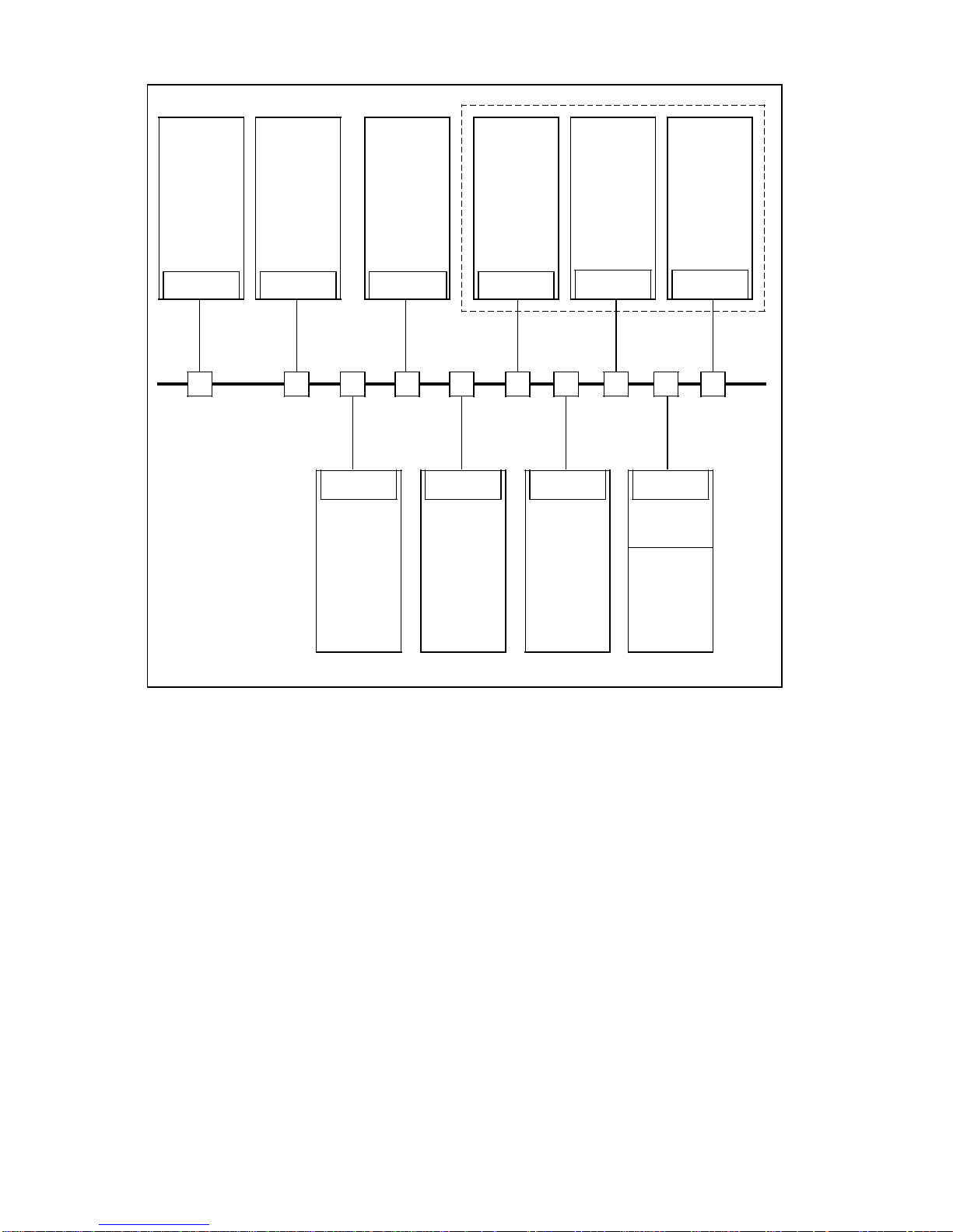
A computer link enables the exchange of data and control information between computers and
controls (e.g. CAD, FMS, ... , NC, RC, SPS ... , as shown in figure SINEC H1) on the initiative
of a computer, control system or operator. The data exchange mainly covers workpiece
programs, tool data, workpiece data, control functions (e.g. NC start, NC stop), operating data
such as status messages, alarm and error messages.
A computer link can be realised using a bus connection or using one of many serial
connections.
The following figure shows the SIEMENS computer systems used for CAD, FMS,
NC Archive and PPC as well as the RC, NC and PLC systems on a common bus cable. If
older systems are to be connected to the bus, e.g. SINUMERIK System 8, this is done via a
gateway station.
1–2
Siemens AG 1989 All Rights Reserved 6FC5 197-0AB20-0BP0
©
SINUMERIK 840/880 (PJ)
08.89 1 General
1.1.1 Computer link
PPC
SINEC
CAD
NC
FMS
Archive
SICOMP
WS 30
WS20/32
SINEC SINEC SINEC
SINEC
SPS
SIMATIC
S5-115U,
135U, 150U
SINUMERIK
SICOMP M
WS20/32
SINEC
NC
850/880
SICOMP M,
SINEC
RC
SIROTEC
RCM 3
Tool
Tool
flow
Presetting
WS20/32
SINEC SINEC
Gateway
SINUMERIK
System 8
device
SINEC
NC
Bus system: SINEC H1
1.1.2 ISO reference model
For the data exchange between systems various prerequisites have to be met by the two
communication partners. Both stations must have compatible physical interfaces, and the form
of information routing, addressing, the type of error checking and the format of the information
have to be agreed by both communication partners.
For this reason, the International Standards Organization (ISO) has established a model for
communication procedures known as the ISO reference model.
Siemens AG 1989 All Rights Reserved 6FC5 197-0AB20-0BP0 1–3
©
SINUMERIK 840/880 (PJ)

1 General 08.89
1.1.2 ISO reference model
It consists of a seven-layer hierarchy which is organized as follows:
• Layer 1 Physical layer
• Layer 2 Data Link layer
• Layer 3 Network layer
• Layer 4 Transport layer
• Layer 5 Session layer
• Layer 6 Presentation layer
• Layer 7 Application layer
Further information on the individual layers and their functions are contained in Section 2.1.1,
”The ISO seven layer model”.
1.1.3 LAN
ISO defines local area networks (LAN) as networks for bit-serial transmission of information
between interconnected independent devices (e.g. computers, microcomputers, programmable
controllers, numerical controls), i.e. the interconnection of autonomous systems.
”These are completely controlled by the users and limited to their site”.
In factory plants, communication and exchange of information between the individual devices is
to take place in such a way that direct data access to all stations is ensured.
1.1.4 MAP
MAP (Manufacturing Automation Protocol) is a new communication protocol which is based on
international and US standards as well as additional specifications by GM. This protocol allows
an open communication in the factory (open networks) i.e. devices of different manufacturers
can be interconnected (opposite: closed networks).
1.1.5 SINEC AP 1
SINEC AP 1 is the Siemens Network Architecture Automation Protocol Version 1, a Siemens
automation protocol. It was developed for the integration of the following systems in a factory
automation system:
• SICOMP computers
• SINUMERIK
• SIROTEC
• SIMATIC S5
• Programmers
• MMC 216
• Concentrators
• Personal computers
• Workstations
The protocol covers the OSI layers 5 to 7. For further information please refer to Section 3.3.1,
”SINEC AP 1 protocol”.
1–4
Siemens AG 1989 All Rights Reserved 6FC5 197-0AB20-0BP0
©
SINUMERIK 840/880 (PJ)

06.91 1 General
1.1.6 Transport connection TPV
1.1.6 Transport connection TPV
The term transport connection describes a virtual connection between two nodes in a network
which, in accordance with the ISO reference model, is also referred to as layer 4 connection
since it reaches to layer 4 of the respective communication partner.
In the case of a serial link, the transport connection need not be specified since an
unambiguous hardware allocation is made by the interface used.
The transport connection is determined by addresses which are clearly assigned when the
network is configured. By means of the addresses the two end points of the transport
connection are allocated.
In the case of a computer link with SINUMERIK 8X0, a transport connection is determined by
the address pair's own Ethernet address, the internal TSAP (Transport Service Access Point)
and the Ethernet and TSAP address of the partner. The addresses or the allocations for the
corresponding transport connection are stored in the interface module of the SINUMERIK 8X0.
The transport connection provides a reliable communication connection to transfer the
application-oriented information and it manages the transfer-specific services.
Several transport connections can be configured for one system. For example, a different
transport connection can be used for the file transfer (NC data exchange) than for the
loading/unloading of tools.
Access to the transport connection is from the application-oriented layers via the transport
service access point (TSAP), which has its own unique address (TSAP address).
Siemens AG 1989 All Rights Reserved 6FC5 197-0AB20-0BP0 1–5
©
SINUMERIK 840/880 (PJ)

1 General 06.91
1.1.7 Logical peer
1.1.7 Logical peer
Logical peer is the symbolic designation for a technological function module in a system, e.g.
in the SINUMERIK 8X0.
A system can contain one or several function modules.
In the case of a bus connection, a "logical peer" is identified by the combination of transport
connection and addressing in the application layer.
One or several logical peers can be served via a TPV transport connection. (When connecting
the SINUMERIK 8X0 to the Siemens FMS only one logical peer per transport connection is
allowed.)
The ”logical peer” is determined by the addressing in the application layer alone in the case of
a serial connection.
If the AS 512 protocol is used, several logical peers can be allocated to one interface.
If an interface is configured without the AS 512 protocol, only one logical peer can be allocated
to it.
In the communication process, a distinction is made between the transmitting and the receiving
logical peer.
The transmitting logical peer is the symbolic designation for the functional unit by which the
message frame was sent whereas the receiving logical peer refers symbolically to the function
module by which the message frame is to be received.
In input direction, the SINUMERIK 8X0 recognizes the sender and/or receiver by means of the
address information contained in the application part of the message frames.
In output direction, the logical peer to which the message frame is to be sent is assigned to
the corresponding connection.
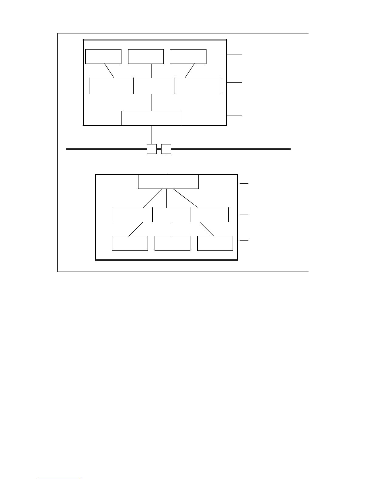
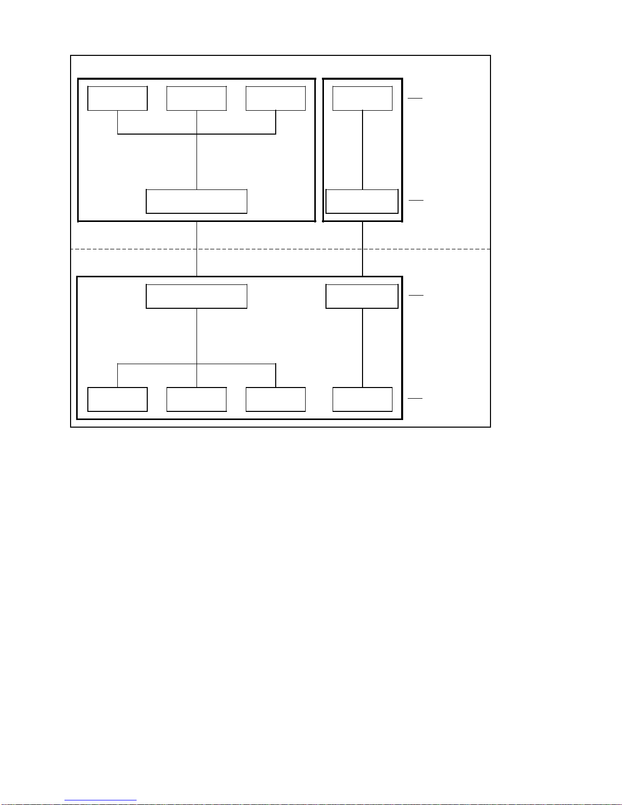
The diagrams below give examples of logical peers both for a production control computer and
for an NC, first for the bus and then for the serial connection.
1–6
Siemens AG 1989 All Rights Reserved 6FC5 197-0AB20-0BP0
©
SINUMERIK 840/880 (PJ)
06.91 1 General
1.1.7 Logical peer
FMS
NCLADE
log.p.1
(TSAP addr.)
NC
TPV5
(TSAP addr.)
BAZSTE
log. p.2
TPV4
(TSAP addr.)
(Ethernet addr.)
(Ethernet addr.)
TPV1
(TSAP addr)
UEBERW
TPV2
log.p.3
TPV6
(TSAP addr.)
TPV3
(TSAP
layer 7
logical peer
layer 4
transport connection
layer 2
Bus
layer 2
layer 4
transport connection
Logical peer in bus connection
log. p.1
NCDAT
log. p.2
GLOBA
log. p.3
MELDG
layer 7
logical peer
Siemens AG 1989 All Rights Reserved 6FC5 197-0AB20-0BP0 1–7
©
SINUMERIK 840/880 (PJ)
1 General 06.91
1.1.7 Logical peer
FMS
NC
NCLADE
log. p. 1
BAZSTE
or or
log. p. 2
Interface 1
Interface 1
UEBERW
log. p. 3
PERI 1
log. p.
Interface 2
Interface 2
Layer 7
logical peer
Layer 2
Layer 2
log. p. 1
NCDAT
Logical peer in serial connection
or or
log. p. 2
GLOBA
log. p. 3
MELDG
Configuring interface 1:
• with AS 512 protocol
• with system 800 ID
Configuring interface 2: (depends on peripheral device)
• with/without AS 512 protocol
• with/without system 800 ID
log. p.
PLC 1
Layer 7
logical peer
1–8
Siemens AG 1989 All Rights Reserved 6FC5 197-0AB20-0BP0
©
SINUMERIK 840/880 (PJ)

06.91 1 General
1.1.7 Logical peer
For the computer (FMS):
Logical peer 1: "Functional unit load NC program,
retransmit and erase NCLADE"
Logical peer 2: "Functional unit manufacturing session, synchronization, end-of-work,
BAZSTE message"
Logical peer 3: "Functional unit line monitoring UEBERW"
For the numerical control:
Logical peer 1: "Functional unit transfer of programs / data to the NC,
messages, initiation of transfer using NCDAT screen form"
Logical peer 2: "Functional unit synchronization, end-of-work, mode switchover GLOBA"
Logical peer 3: "Functional unit alarms, operator interrupt, status message MELDG"
Logical peer: PLC1
For the peripheral device:
Logical peer: PERI1 (any name may be selected).
Siemens AG 1989 All Rights Reserved 6FC5 197-0AB20-0BP0 1–9
©
SINUMERIK 840/880 (PJ)

06.91 2 Local Area Networks
2.1 Bus connection
2
As automation in manufacturing increases, so does the necessity to exchange data between
different manufacturing systems such as controls, robots, conveyor systems and higher-level
systems as for instance host computers.
In the past, information was transferred between the individual systems by people. This
method is time-consuming and prone to errors.
Local area networks (LANs), interconnecting all systems involved in the manufacturing and
planning process, provide a remedy for this problem. LANs ensure secure and quick data
transfer within manufacturing facilities as well as to higher-level systems.
Special requirements must be met by LANs in the tough environment of industrial
manufacturing:
• A universal basis for different stations (terminals)
• Insensitivity to external mechanical and electric stresses
• High availability
• Simple extendability
Various configurations are possible for local area networks. They are different in the type of
connection and of data transmission.
For the computer link with SINUMERIK 8X0, bus and star connections are of special
importance. These are described below in greater detail.
Local Area Networks
2.1
Networks with bus architectures generally use serial data transmission and often a timedivision multiplex method to maintain the data flow. The bus topology has the following
advantages:
• Passive transport medium, only needs a coaxial cable terminating with the correct
• Depending on the allocation procedure, the network control is concentrated at one station
• Easy reconfiguration, stations can be connected or disconnected as desired;
• The failure of one station does not affect the operation of the network, provided the
The only disadvantage of the bus topology is that it uses a common transport medium: if the
cable is damaged, all nodes are affected.
Suitable transport media for local networks are:
• twisted copper lines,
• coaxial cables,
• broad band coaxial cables
• fibre optic cables.
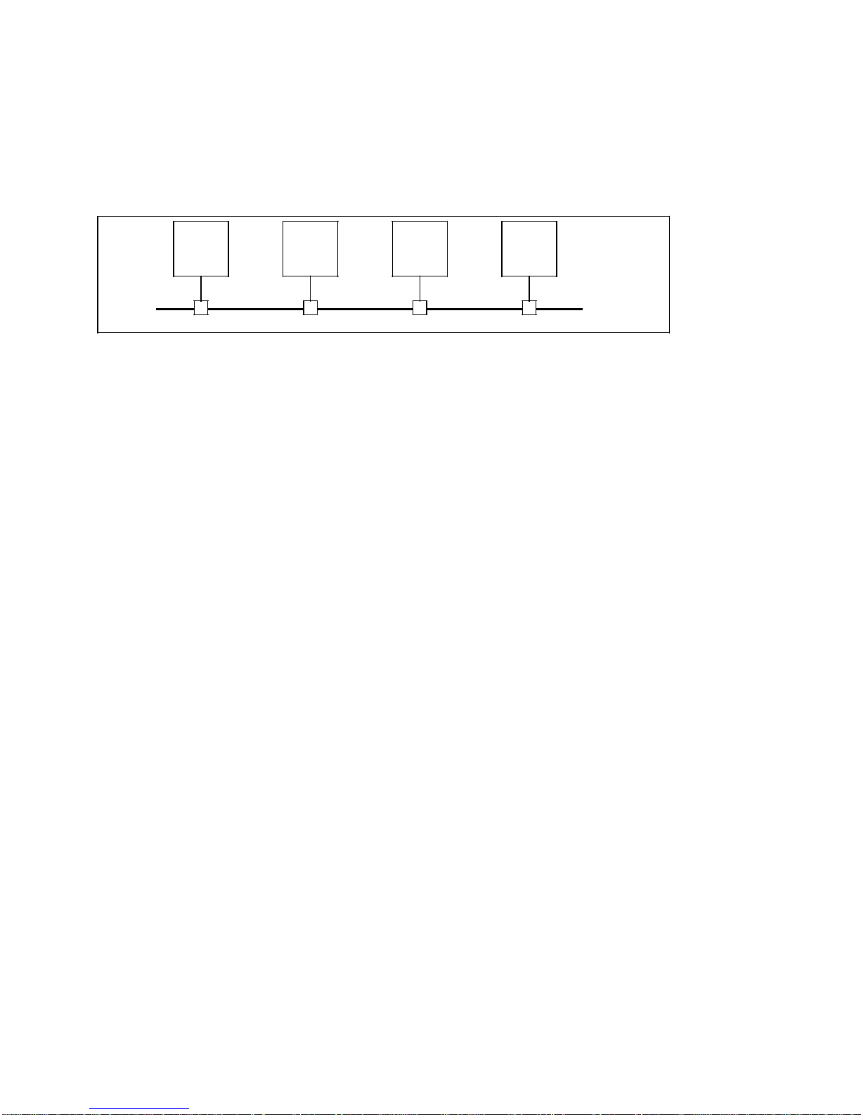
The bus consists of a common resource, the bus cable, and branches to each station.
Bus connection
impedance;
or distributed over all connected stations;
allocation method is suited for the purpose.
Siemens AG 1989 All Rights Reserved 6FC5 197-0AB20-0BP0 2–1
©
SINUMERIK 840/880 (PJ)
2 Local Area Networks 08.89
2.1 Bus connection
Since the bus cable can be run throughout the facility, only short branch cables are necessary.
The cable costs are thus reduced, and the expenditure for extending the system remains
linear.
Basically, each connected station can communicate with another one over the common bus
cable. However, since the bus is a common resource for all stations, its use has to be
controlled by an access method in order to prevent one station from interfering with the
operation of another one.
Process communication bus topology
Advantages of bus systems:
• Low cable expenses
• Cost-saving even with few nodes connected
• Extension costs are linear
• Any traffic between all units is possible simultaneously
• Bus is a common resource access method
2.1.1 The ISO seven layer model
Various specifications have to be observed for the communication between systems. Both
partners must have compatible physical interfaces, they must speak the same "language", and
they must "mean" the same thing when they say something.
To ensure this between the peers on a local area network, ISO (International Standardisation
Organization) has defined a hierarchical layer model.
In this model, a layer is defined as a program or a process that communicates with the
corresponding process of its peer on the same layer .
The layers function as follows:
A layer receives a job from the next higher layer. It processes the job with its own resources
and then passes a job to the next lower level. This means that to handle the job the layer uses
its own resources as well as the services made available by the next lower layer.
Example: 3 layer model
A "humanized" example of a 3 layer model may help to explain the layer structure:
Two scientists would like to exchange their findings. Scientist 1 lives in Japan and speaks
Japanese, scientist 2 lives in Spain and speaks Spanish. The two scientists represent layer 3.
2–2
Siemens AG 1989 All Rights Reserved 6FC5 197-0AB20-0BP0
©
SINUMERIK 840/880 (PJ)
08.89 2 Local Area Networks
2.1.1 The ISO seven layer model
In order to exchange information, each of them hires a translator. To understand each other,
the translators must agree on a common language, e.g. English. The translators constitute
layer 2.
In order to transmit the information, the translators deliver their texts to the respective post
office.
To send the texts, the employees of the post offices agree on a common transmission method
(e.g. telex or fax). They constitute layer 1.
The procedure is as follows:
Scientist 1 (layer 3) hands the message written in Japanese to his translator (layer 2). The
translator translates the text into English and delivers it to the post office (layer 1). The post
office in Japan transmits the text by fax to the respective post office in Spain. The translator in
Spain (layer 2) receives the fax from the post office employee and translates it from English
into Spanish. Scientist 2 (layer 3) receives a Spanish text from his translator which contains
the thoughts of his Japanese colleague.
Irrespective of the common language the translators have chosen (e.g. French instead of
English) or the type of transmission selected by the post (e.g. telex instead of fax) the
scientists receive the message in a language they understand.
This example shows that individual layers can change their agreements (protocols) without
affecting the other layers. This is the main reason for using the layer structure for networks.
Scientist 1
(Japanese)
Translator 1
(Japanese/English)
Post office 1
(fax)
layer 3
layer 2
layer 1
Scientist 2
(Spanish)
Translator 2
(English/Spanish)
Post office 2
(fax)
3 layer model
Siemens AG 1989 All Rights Reserved 6FC5 197-0AB20-0BP0 2–3
©
SINUMERIK 840/880 (PJ)
2 Local Area Networks 08.89
2.1.1 The ISO seven layer model
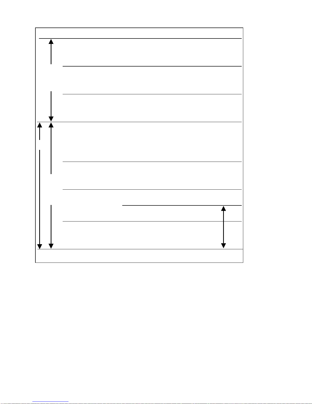
Layer Designation Function Example
Applicationoriented
layer
CP
Transportoriented
layer
Application Application functions
7
6
5
4
3
2
1
Layer (Information processing
Presentation Data representation • Common
Layer language
Session Communication control (open,
Layer Synchronization end, abort)
Transport Transport control
Layer Flow control
Network Network connections X.25
Layer Addressing of other
Data Link
Layer
Physical Physical characteristics of
Layer the transmission path Yellow Cable
• File transfer
•
)
Blocking conversation text
Acknowledgement
Connection establishment/release
networks
Reliable transfer CRC check
Allocation method CSMA/CD
Remote
Control
• Coordination
•
Transmission of
IEEE*
802.3
Protocol architecture for local area networks according to ISO
2–4
* Ethernet
Siemens AG 1989 All Rights Reserved 6FC5 197-0AB20-0BP0
©
SINUMERIK 840/880 (PJ)

08.89 2 Local Area Networks
2.1.1 The ISO seven layer model
ISO layers
The layer model defined by ISO includes 7 layers:
The transport-oriented layers (1 to 4) and the user-oriented layers (5 to 7). Each of these 7
layers provides services. In order to make its services available, a layer of a network entity
must communicate with the same layer of its peer. This communication process, including the
means used for it, is referred to as a protocol.
Layer 1: Physical Layer = Physical characteristics of the transmission path, e.g.
Yellow Cable
This layer defines the physical operation such as electrical (current-voltage level) and
mechanical parameters between 2 peers, in order to be able to transmit data.
It provides services in order to activate, maintain and deactivate physical connections for
transmission of data between two data-link entities.
"A medium must be available, for example air, telephone line etc.".
Layer 2: Data Link Layer = 2a Access method,
such as CSMA/CD 2b Reliable transfer, e.g CRC check
On this level, the access mechanism is defined that ensures that only one node sends data
over the bus at a given time. The layer provides functional and procedural services in order to
establish, maintain and release data link connections. It detects and possibly corrects errors
which may occur in the subordinate physical layer. It enables the network layer to control the
interconnection of data circuits within the physical layer, e.g. to interconnect partial sections
and to switch to alternate paths using different combinations.
Layer 1 and 2 ensure that information can be transmitted and that access to the transmission
medium is controlled.
Layer 3: Network Layer = Network connections/addressing of other networks
The network layer provides the means to establish, maintain and terminate connections
between systems as well as networks.
"Rules for routing must be specified when using several transmission sections, e.g. route
switching of several sections in a communication network".
Layer 4: Transport Layer = Transport control: Flow control, blocking,
acknowledgement, establishment and release of connection, transmission
of the conversation text.
The function of the transport layer is to provide a universal transport service in cooperation
with the services of the lower-level layers.
It separates the application-oriented from the transmission-oriented layers.
Siemens AG 1989 All Rights Reserved 6FC5 197-0AB20-0BP0 2–5
©
SINUMERIK 840/880 (PJ)

2 Local Area Networks 08.89
2.1.1 The ISO seven layer model
The transport layer ensures data security and data consistency. It manages the transport
control requirements and provides the following services:
• Flow control:
A message frame is sent only if the remote station is able to receive it, e.g. if sufficient
receive buffer is available.
• Blocking:
Message frames longer than e.g. 512 bytes are blocked automatically so that long
message frames do not block the line.
• Acknowledgement:
Acknowledgement of a message frame received without error by the transport layer (no
user acknowledgement).
To implement these functions transport connections (logical channels) are established.
Establishment/release of these connections are effected automatically by the services of
layer 4.
Layer 5: Session Layer = Communication control/synchronization e.g. coordination
of the conversation (opening, end, abort)
The session layer provides means necessary for cooperating entities of the higher-level
presentation layer (layer 6) to organize and synchronize their dialogue and manage their data
exchange. For this purpose the session layer provides services to establish a session
connection between two entities of the higher-level presentation layer and to support actions
required for a proper data exchange.
The session layer can be designed with more or less comfortable functions.
There are only user-specific aspects for these and the higher layers.
Layer 6: Presentation Layer = Data representation e.g. common language
The Presentation Layer is concerned with the representation
• of the data which are transmitted between corresponding entities of the higher-level
application layer. This data representation is also called data syntax.
• of the data structure to which entities of the application layer refer in order to perform
actions.
The presentation layer is concerned only with the representation (syntax), but not with its
meaning (semantics). The semantics is only known to the application layer.
"Receiver and transmitter must have the information represented in a form known to everyone
(common language). If the representation forms differ (the transmitter speaks Japanese, the
receiver speaks Spanish), a translator is required, e.g. an interpreter for Japanese and
Spanish. However, an intermediate language, for example English, might be chosen, and both
the transmitter and the receiver employ an interpreter; the transmitter for Japanese-English
and the receiver for English-Spanish".
2–6
Siemens AG 1989 All Rights Reserved 6FC5 197-0AB20-0BP0
©
SINUMERIK 840/880 (PJ)
08.89 2 Local Area Networks
2.1.1 The ISO seven layer model
Layer 7: Application Layer = Application function (information processing) e.g. File
Transfer, Remote Job Control
The application layer is the highest of the 7 layers of the OSI model and does not provide any
services to a higher layer with regard to the integration of open systems (OSI environment). It
rather provides the means for the application processes, so that these can access the OSI
environment. The application layer serves as a window between corresponding application
processes which are using the integration of (open) systems to exchange meaningful
information.
Each application process is represented to its peer by the application layer entity.
"Even when the same language is spoken and the same terms are used, a term can have
different meanings, when for example the same terms are used in a different environment. It
must therefore be ensured that the meaning of one or a combination of terms is identical for
both the transmitter and the receiver".
2.1.2
Access methods
Two access methods are today at the centre of both theory and practice:
The token principle and the collision principle (CSMA/CD, Ethernet). There are already several
variants of both procedures, however one variant of each has been standardized.
Process communication/access methods
Allocation systems/ Contention systems/
token procedures collision principle
(CSMA/CD, Ethernet)
• An authorization to send • Theoretically, all stations
(token) exists, which is held by in a network can transmit simultaneously.
one station onlyat any time.
• In case of a collision,
• The authorization to transmit is this is recognized and the stations
passed on to another station repeat transmission after
after a given period of time. different times.
• Each station receives one • High transmission capacity
authorization to transmit keeps the number of
after a defined time interval. collisions low
Siemens AG 1989 All Rights Reserved 6FC5 197-0AB20-0BP0 2–7
©
SINUMERIK 840/880 (PJ)
• A probability factor
can be specified with which a
message will be transmitted.

2 Local Area Networks 06.91
2.1.3 SINEC H1
2.1.3 SINEC H1
SINEC (Siemens Network Architecture) stands for the integrated communication system of the
Siemens automation systems.
This includes:
• The communication network
• The respective module which establishes the connection to the communication network
(interface module)
• Protocols and services used for transmission of data between the systems.
SINEC H1 is a baseband transmission communication system to IEEE 802.3 (Ethernet).
It is based on the reference model of the international standard committee ISO for open
communication aiming at operating different types of devices together.
The SINEC H1 layers 1 and 2a (transmission procedure and network access) are based on the
IEEE 802.3 standard. These layers are concerned with data transmission and the access of
the nodes to the network. The access method is based on the collision principle used by
Ethernet. SINEC H1 provides for the higher layers a standardardized interface which is
independent of the access method.
Layer 3 of the ISO reference model is required for large networks. This layer is inactive with
SINEC H1.
For layer 4, SINEC H1 has implemented the ISO transport protocol (ISO-8073 class 4).
The functions of layers 1 to 4 are implemented by SINEC H1 on communication processors
which are located on the interface module. They offer the user a series of services which
relieve him/her from work-intensive procedures.
At present there are no uniform international standards for layers 5 to 7 of the OSI model for
the NC applications. As a first step to standardization of OSI layers 5 to 7 within the company,
Siemens have therefore defined the AP 1 automation protocol. It is suitable for use on all
Siemens automation devices.
For more details on the SINEC AP 1 protocol please refer to Section 3.4, Protocols.
The most important features of SINEC H1 are:
• Topology: bus (line) consisting of one or several segments
• Transmission medium: shielded coaxial cable; 50 ohms
• Segment length: max. 500 metres
• Connectable nodes per segment: max. 100
• Transmission method: baseband
• Data transfer rate: 10 Mbits/sec.
• Bus access method: collision principle
2–8
Siemens AG 1989 All Rights Reserved 6FC5 197-0AB20-0BP0
©
SINUMERIK 840/880 (PJ)
08.89 2 Local Area Networks
2.2 Serial connection
2.2 Serial connection
In contrast to bus connection, with which all nodes are physically connected in parallel to a
common bus cable, every connection between two peers is implemented with a separate
connection cable in the case of serial connection.
Procedures agreed between the two nodes ensure the controlled data exchange between the
connected peers.
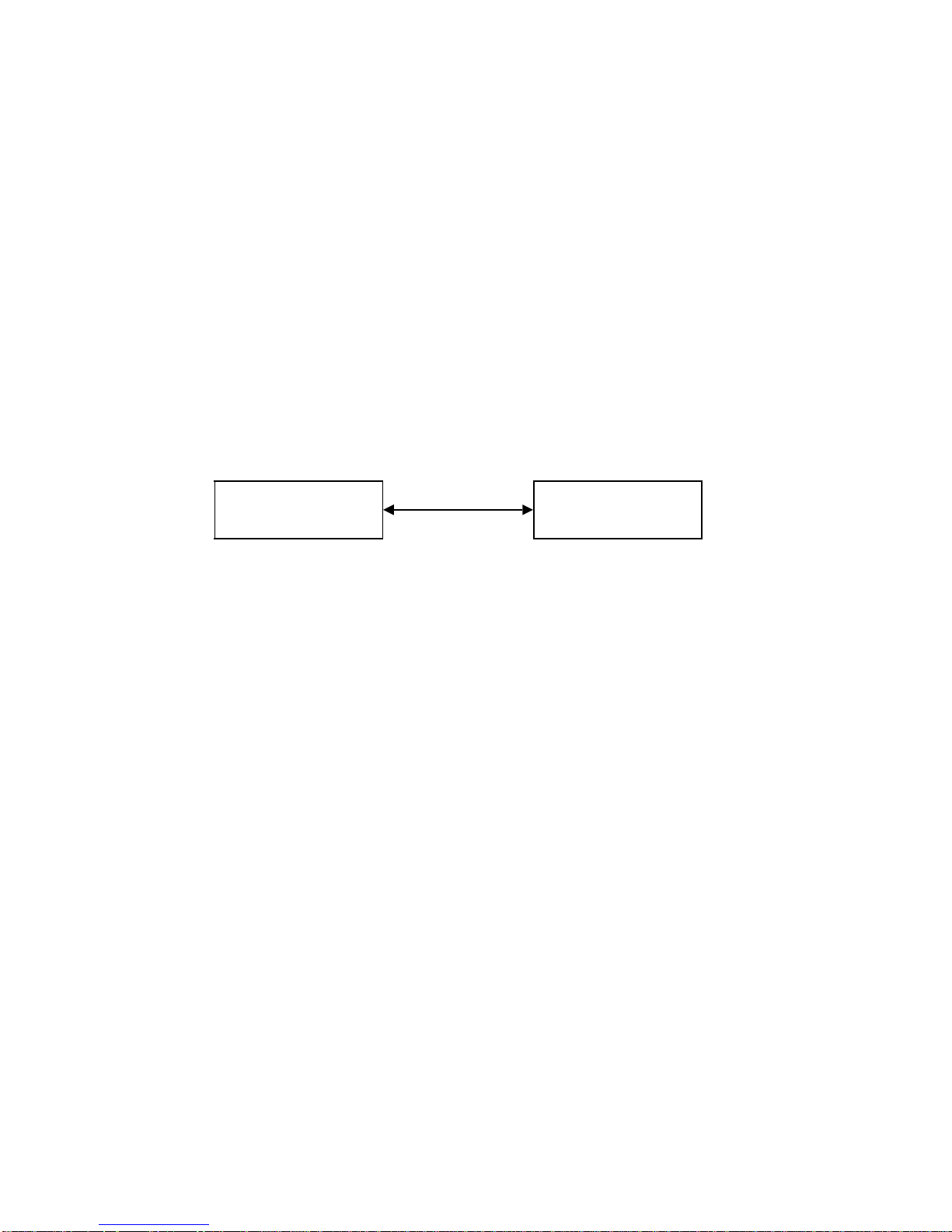
2.2.1 Point-to-point connection
The point-to-point connection ensures the communication between two peers. This is the
simplest form of process communication if it is established as direct connection (separate line)
between two nodes.
Complex communication relations can be logically traced back (to a large extent) to a
combination of these simplest relationships.
If exactly this case occurs in practice, even the simplest type of connection is adequate.
Process communication point-to-point connection
Station 1 Station 2
• Data transfer between two peers
• Simplest case of process communication
• Simplest type of connection is adequate (4-wire)
• Example: PLC/PG traffic on SIMATIC systems
Exactly one physical point-to-point connection corresponds to each connection i.e. each
existing request of a unit to exchange data with a partner station.
Depending on the number of nodes involved, cabling expenditure is high and costs will
increase progressively if a further station is to be connected and wishes to communicate with
all other stations. Larger networks cannot be implemented due to the required number of
interfaces per unit increasing considerably.
Fault diagnosis is relatively simple since an unambiguous allocation is possible according to
communication request and physical implementation.
Siemens AG 1989 All Rights Reserved 6FC5 197-0AB20-0BP0 2–9
©
SINUMERIK 840/880 (PJ)

2 Local Area Networks 08.89
2.2.2 Star connection
2.2.2 Star connection
The star topology is today probably the most widely used type of connection in a hierarchically
organized process.
Although the cabling expenditure is lower than with meshed networks, it is still relatively high,
as in most cases the distances between master and the lower-level controls are rather long.
The master station must have one interface for every node; with larger systems, the masters
themselves can form a hierarchical structure.
The internode communication between two lower-level systems has to be executed over the
master which results in an additional burden and an availability bottleneck.
Process communication star topology
• Corresponds to the hierarchical organization of the process
• Linear extension cost
• Only at the master station are many interfaces necessary
• Internode communication is executed via the master node
• Master station is availability bottleneck
• Simple diagnostics
• Simple to configure
• Different transmission media can be used
2–10
Siemens AG 1989 All Rights Reserved 6FC5 197-0AB20-0BP0
©
SINUMERIK 840/880 (PJ)
08.89 2 Local Area Networks
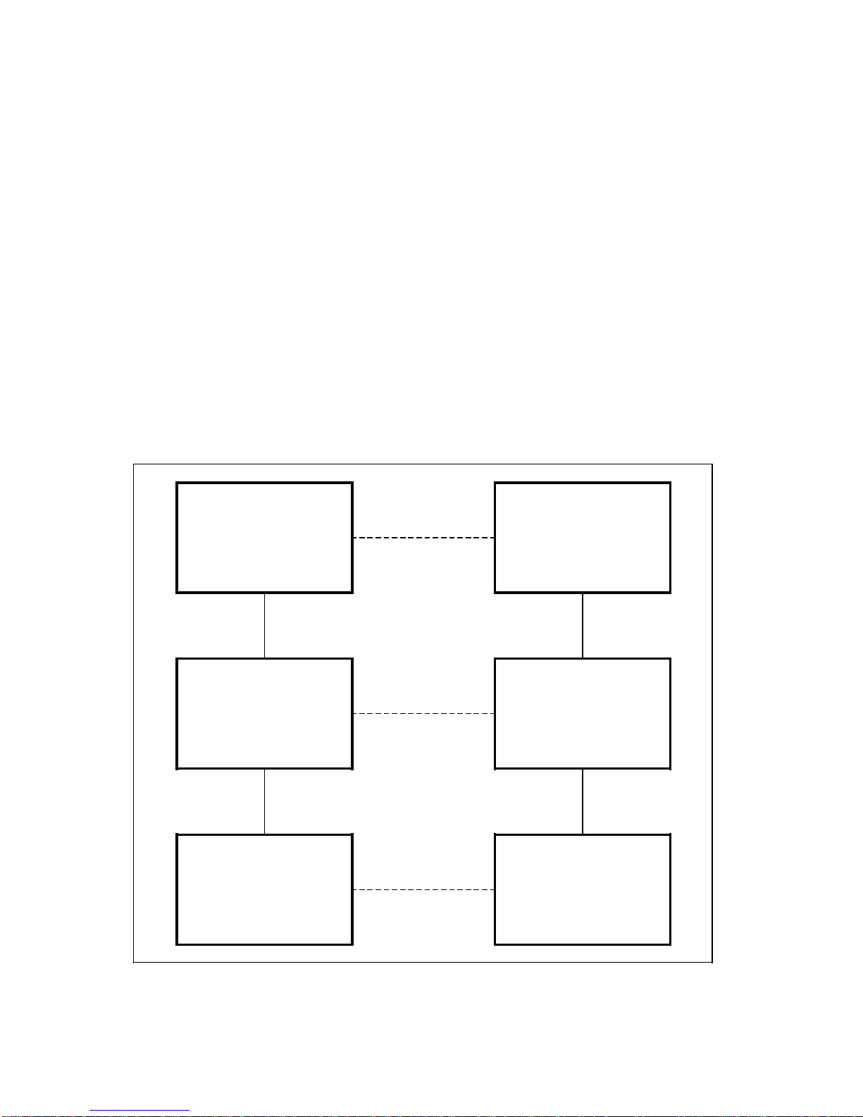
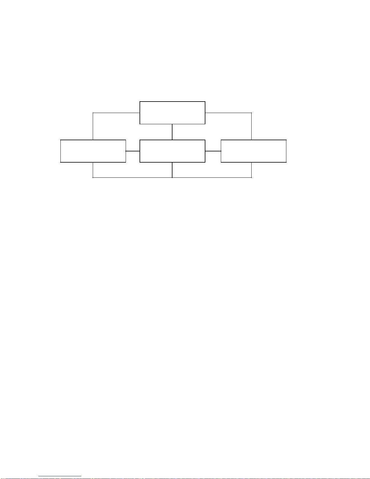
2.2.3 Meshed network
2.2.3 Meshed network
Meshed networks have the advantage that the individual stations are connected with several
nodes via point-to-point connections.
Internode communication is possible, due to which the availability increases, since - in contrast
to the star network - the master does not cause an availability bottleneck.
Process communication meshed network
• 1 to 1 allocation of logical connections to physical communication channels
• High cable cost
• Extension costs highly progressive
• Very large number of interfaces required per unit
• Simple diagnostics
• Failsafe
• Internode communication is possible
Siemens AG 1989 All Rights Reserved 6FC5 197-0AB20-0BP0 2–11
©
SINUMERIK 840/880 (PJ)
2 Local Area Networks 08.89
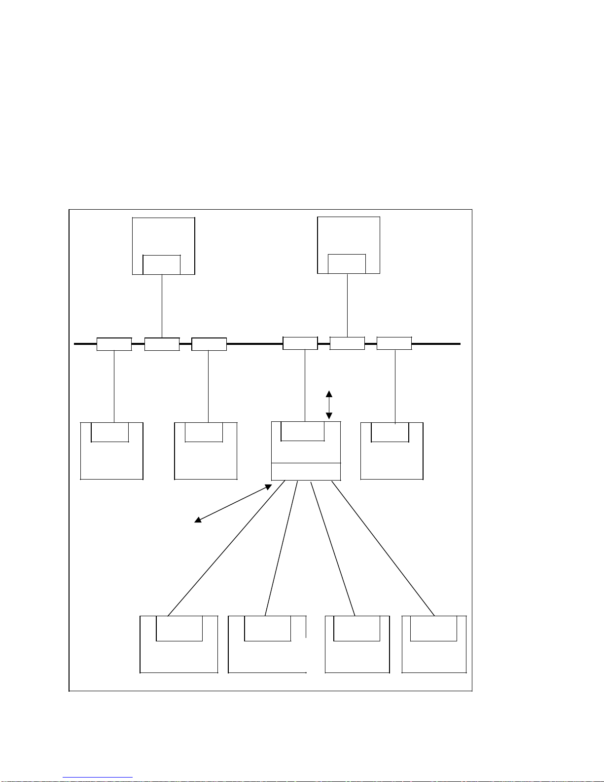
2.3 Bus and serial connections
2.3 Bus and serial connections
In addition to local area networks featuring either only bus connections or only serial
connections, there are mixed forms of networks.
The following figure shows a network with different connection types, using the example of a
NC system. In this example the CNC is the master station of a star network and at the same
time a node on the bus network.
The CNC is connected to the higher-level host systems (e.g. host computer) and the systems
at the same level (e.g. RC controls) via bus connection.
Data transfer between the CNC and the secondary systems (e.g. read stations) is via serial
connections.
SINEC
TPS
FMS
SINEC
SINEC
RC
Programmer
connection
CP231A
CNC
CP315/373
PPC
SINEC
Bus
SINEC H1
SINEC
Measuring
machine
Programmer
connection
Serial
interface
Read station 1
Tool data
2–12
Serial
interface
Read station 2
Tool data
Siemens AG 1989 All Rights Reserved 6FC5 197-0AB20-0BP0
©
Serial
interface
Read stat.
Pal. - data
Serial
interface
. . .
SINUMERIK 840/880 (PJ)

06.91 3 Interface Modules
3 Interface Modules
For the computer link with SINUMERIK 8X0, there are corresponding interface modules which
are plugged in the COM area.
The modules are the interface between the local area networks or point-to-point connections
and the control system. The services at the physical layer through to the application layer such
as procedures, test methods, access mechanisms etc. required for communication are
implemented on the interface modules.
The connection-specific and application-oriented parameters are stored on the interface
modules in lists which are compiled by means of a configuring software executable on the PG
685.
The following interface modules are available:
• Bus interface module (CP 231A)
The bus interface module is referred to as CP 231A. It allows connection to the SINEC H1
bus.
• Basic board for serial connection (CP 315)
The basic board for serial connections provides a serial interface conforming with
RS 232C/TTY. The connector pin assignment determines whether the serial interface is
used as RS 232C or TTY interface. The board is called CP 315.
• Expansion board for serial connection (CP 373)
To complement the CP 315 basic board there is an expansion board with the designation
CP 373. It is mounted on the side of the basic board and can be operated only together
with it. The CP 373 offers three further serial interfaces.
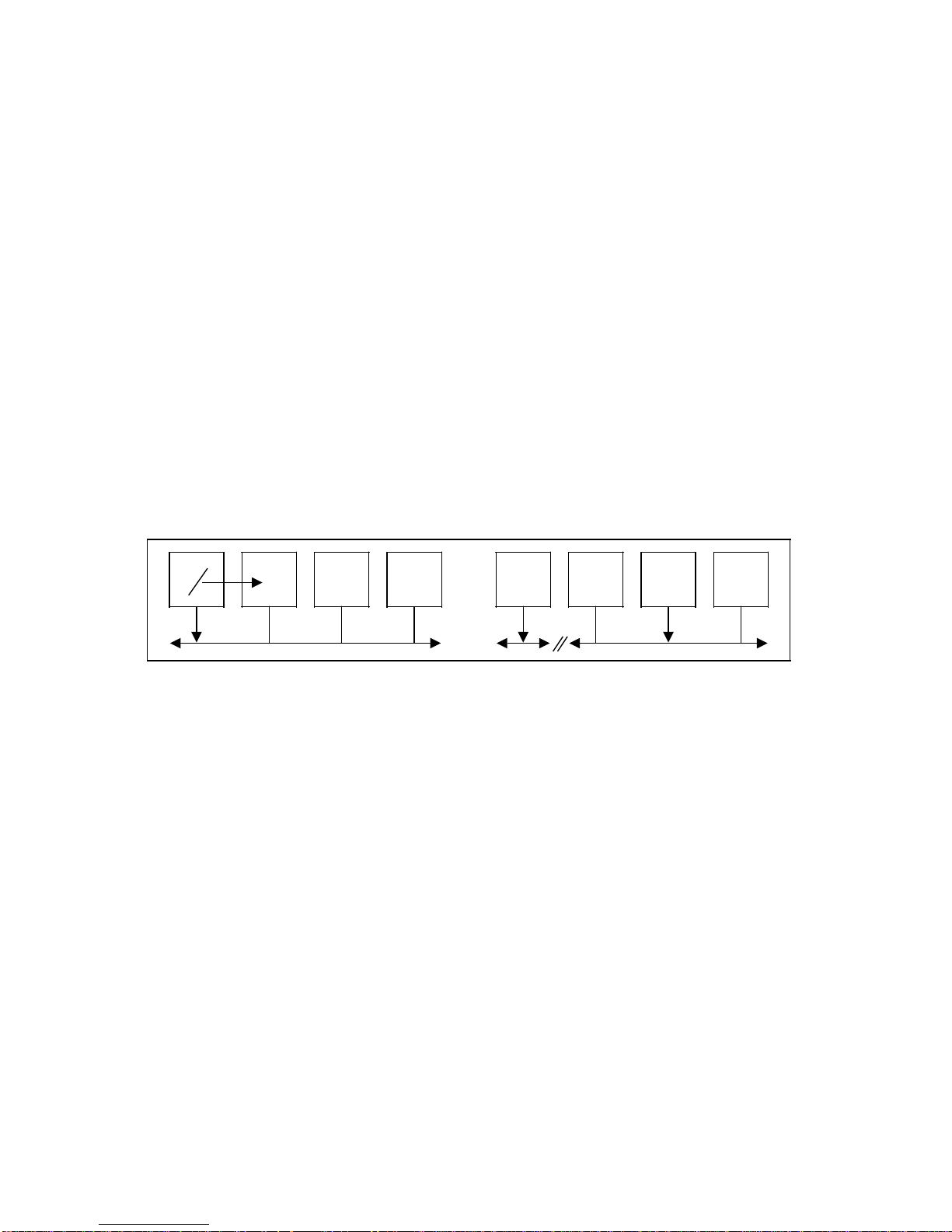
Dependent on the frame variant or the SINUMERIK 880 configuration, various configurations
are possible for the interface modules.
The following figure and table show examples of typical variants.
At application layer, the addressing concept of the computer link message frames is identical
for both bus and serial interface modules. It is implemented on the interface module by means
of SINUMERIK-specific input and output lists. In the case of a serial interface module,
message frames not corresponding to the SINUMERIK specifications can also be processed.
The addressing is carried out via internal lists.
Message frames can be transmitted between the bus interface and the serial interface module,
i.e. the message frames are not processed in the SINUMERIK but are passed from one
interface module to the other.
Siemens AG 1989 All Rights Reserved 6FC5 197-0AB20-0BP0 3–1
©
SINUMERIK 840/880 (PJ)
 Loading...