

Siemens 7SR210, 7SR220, 7SR21, 7SR22 Application Manual

The copyright and other intellectual property rights in this document, and in any model or article produced from it
(and including any registered or unregistered design rights) are the property of Siemens Protection Devices
Limited. No part of this document shall be reproduced or modified or stored in another form, in any data retrieval
system, without the permission of Siemens Protection Devices Limited, nor shall any model or article be
reproduced from this document unless Siemens Protection Devices Limited consent.
While the information and guidance given in this document is believed to be correct, no liability shall be accepted
for any loss or damage caused by any error or omission, whether such error or omission is the result of
negligence or any other cause. Any and all such liability is disclaimed.
©2011 Siemens Protection Devices Limited
7SR210 Non-Directional Relay
7SR220 Directional Relay
Applications Guide
(Software Version 2435H85008R7a-7a) (7SR210)
(Software Version 2435H85009R7a-7a) (7SR220)

7SR210 & 7SR220 Applications Guide
Document Release History
This document is issue 2011/05.
2011/05 First issue
Page 2 of 40 ©2011 Siemens Protection Devices Limited

7SR210 & 7SR220 Applications Guide
Contents
Document Release History....................................................................................................................2
Section 1: Common Functions .............................................................................................................5
1.1 Multiple Settings Groups...........................................................................................................5
1.2 Binary Inputs .............................................................................................................................6
1.3 Binary Outputs ..........................................................................................................................9
1.4 LEDs .........................................................................................................................................9
Section 2: Protection Functions.........................................................................................................11
2.1 Time delayed overcurrent (51/51G/51N) ................................................................................11
2.1.1 Selection of Overcurrent Characteristics ...................................................................12
2.1.2 Reset Delay................................................................................................................13
2.2 Voltage dependent overcurrent (51V).....................................................................................14
2.3 Cold Load Settings (51c) ........................................................................................................14
2.4 Instantaneous Overcurrent (50/50G/50N) ..............................................................................15
2.4.1 Blocked Overcurrent Protection Schemes.................................................................15
2.5 Sensitive Earth-fault Protection (50SEF) ................................................................................17
2.6 Directional Protection (67) ......................................................................................................18
2.7 Directional Earth-Fault (50/51G, 50/51N, 51/51SEF) .............................................................21
2.8 High Impedance Restricted Earth Fault Protection (64H) ......................................................22
2.9 Negative Phase Sequence Overcurrent (46NPS) ..................................................................24
2.10 Undercurrent (37)....................................................................................................................24
2.11 Thermal Overload (49)............................................................................................................24
2.12 Under/Over Voltage Protection (27/59) ..................................................................................25
2.13 Neutral Overvoltage (59N) ......................................................................................................26
2.13.1 Application with Capacitor Cone Units.......................................................................27
2.13.2 Derived NVD Voltage .................................................................................................27
2.14 Negative Phase Sequence Overvoltage (47) .........................................................................27
2.15 Under/Over Frequency (81) ....................................................................................................28
Section 3: CT Requirements ...............................................................................................................29
3.1 CT Requirements for Overcurrent and Earth Fault Protection ...............................................29
3.1.1 Overcurrent Protection CTs .......................................................................................29
3.1.2 Earth Fault Protection CTs.........................................................................................29
3.2 CT Requirements for High Impedance Restricted Earth Fault Protection..............................29
Section 4: Control Functions..............................................................................................................30
4.1 Auto-reclose Applications .......................................................................................................30
4.1.1 Auto-Reclose Example 1............................................................................................31
4.1.2 Auto-Reclose Example 2 (Use of Quicklogic with AR) ..............................................32
4.2 Quick Logic Applications.........................................................................................................33
4.2.1 Auto-Changeover Scheme Example..........................................................................33
Section 5: Supervision Functions ......................................................................................................34
5.1 Circuit-Breaker Fail (50BF) .....................................................................................................34
5.1.1 Settings Guidelines ....................................................................................................34
5.2 Current Transformer Supervision (60CTS).............................................................................36
5.3 Voltage Transformer Supervision (60VTS).............................................................................37
5.4 Trip-Circuit Supervision (74TCS)............................................................................................38
5.4.1 Trip Circuit Supervision Connections.........................................................................38
5.5 Inrush Detector (81HBL2) .......................................................................................................40
5.6 Broken Conductor / Load Imbalance (46BC)..........................................................................40
5.7 Circuit-Breaker Maintenance ..................................................................................................40
©2011 Siemens Protection Devices Limited Page 3 of 40

7SR210 & 7SR220 Applications Guide
Page 4 of 40 ©2011 Siemens Protection Devices Limited
List of Figures
Figure 1.1-1 Example Use of Alternative Settings Groups.......................................................................5
Figure 1.2-1 Example of Transformer Alarm and Trip Wiring ..................................................................6
Figure 1.2-2 – Binary Input Configurations Providing Compliance with EATS 48-4 Classes
ESI 1 and ESI 2 ...................................................................................................................8
Figure 1.4-1 LED configuration via the LED Matrix tab............................................................................9
Figure 1.4-2 LED configuration via the Settings \ OUTPUT CONFIG \ LED CONFIG menu ................10
Figure 2.1-1 IEC NI Curve with Time Multiplier and Follower DTL Applied ...........................................11
Figure 2.1-2 IEC NI Curve with Minimum Operate Time Setting Applied ..............................................12
Figure 2.1-3 Reset Delay........................................................................................................................13
Figure 2.4-1 General Form of DTL Operate Characteristic....................................................................15
Figure 2.4-2 Blocking Scheme Using Instantaneous Overcurrent Elements .........................................16
Figure 2.5-1 Sensitive Earth Fault Protection Application......................................................................17
Figure 2.6-1 Directional Characteristics ................................................................................................18
Figure 2.6-2 Phase Fault Angles............................................................................................................18
Figure 2.6-3 Application of Directional Overcurrent Protection..............................................................19
Figure 2.6-4 Feeder Fault on Interconnected Network ..........................................................................20
Figure 2.7-1 Earth Fault Angles .............................................................................................................21
Figure 2.8-1 Balanced and Restricted Earth-fault protection of Transformers.....................................22
Figure 2.8-2 Composite Overcurrent and Restricted Earth-fault Protection .........................................23
Figure 2.11-1 Thermal Overload Heating and Cooling Characteristic..............................................24
Figure 2.13-1 NVD Application...............................................................................................................26
Figure 2.13-2 NVD Protection Connections ...........................................................................................26
Figure 2.15-1 Load Shedding Scheme Using Under-Frequency Elements ...........................................28
Figure 4.1-1 Sequence Co-ordination ....................................................................................................30
Figure 4.1-2 Example of Logic Application.............................................................................................32
Figure 4.2-1 Example Use of Quick Logic..............................................................................................33
Figure 5.1-1 - Circuit Breaker Fail ..........................................................................................................34
Figure 5.1-2 - Single Stage Circuit Breaker Fail Timing.........................................................................35
Figure 5.1-3 - Two Stage Circuit Breaker Fail Timing ............................................................................35
Figure 5.4-1:Trip Circuit Supervision Scheme 1 (H5) ............................................................................38
Figure 5.4-2:Trip Circuit Supervision Scheme 2 (H6) ............................................................................39
Figure 5.4-3:Trip Circuit Supervision Scheme 3 (H7) ............................................................................39
List of Tables
Table 2-1 Application of IDMTL Characteristics 13
Table 5-2 Determination of CT Failure (1 or 2 Phases) 36
Table 5-3 Determination of VT Failure (1 or 2 Phases) 37
Table 5-4 Determination of VT Failure (3 Phases) 37
Table 5-5 Magnetic Inrush Bias 40
7SR210 & 7SR220 Applications Guide
Section 1: Common Functions
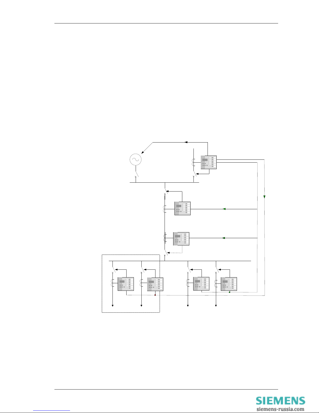
1.1 Multiple Settings Groups
Alternate settings groups can be used to reconfigure the relay during significant changes to system conditions
e.g.
Primary plant switching in/out.
Summer/winter or day/night settings.
switchable earthing connections.
Loss of Grid connection (see below)
RADIAL SUBSTATION
Start
generators
Select alternate
settings group
Local
Generation
Industrial system draws power from grid
system during normal operation
Relays normally use settings group 1
On loss of mains:
Local generation switched in.
Non essential loads tripped
Relays on essential circuits switched to
settings group 2 to reflect new load and
fault currents
Non-essential
loads
Trip non-essential loads
Figure 1.1-1 Example Use of Alternative Settings Groups
©2011 Siemens Protection Devices Limited Page 5 of 40
7SR210 & 7SR220 Applications Guide
1.2 Binary Inputs
Each Binary Input (BI) can be programmed to operate one or more of the relay functions, LEDs or output relays.
These could be used to bring such digital signals as Inhibits for protection elements, the trip circuit supervision
status, autoreclose control signals etc. into the Relay.
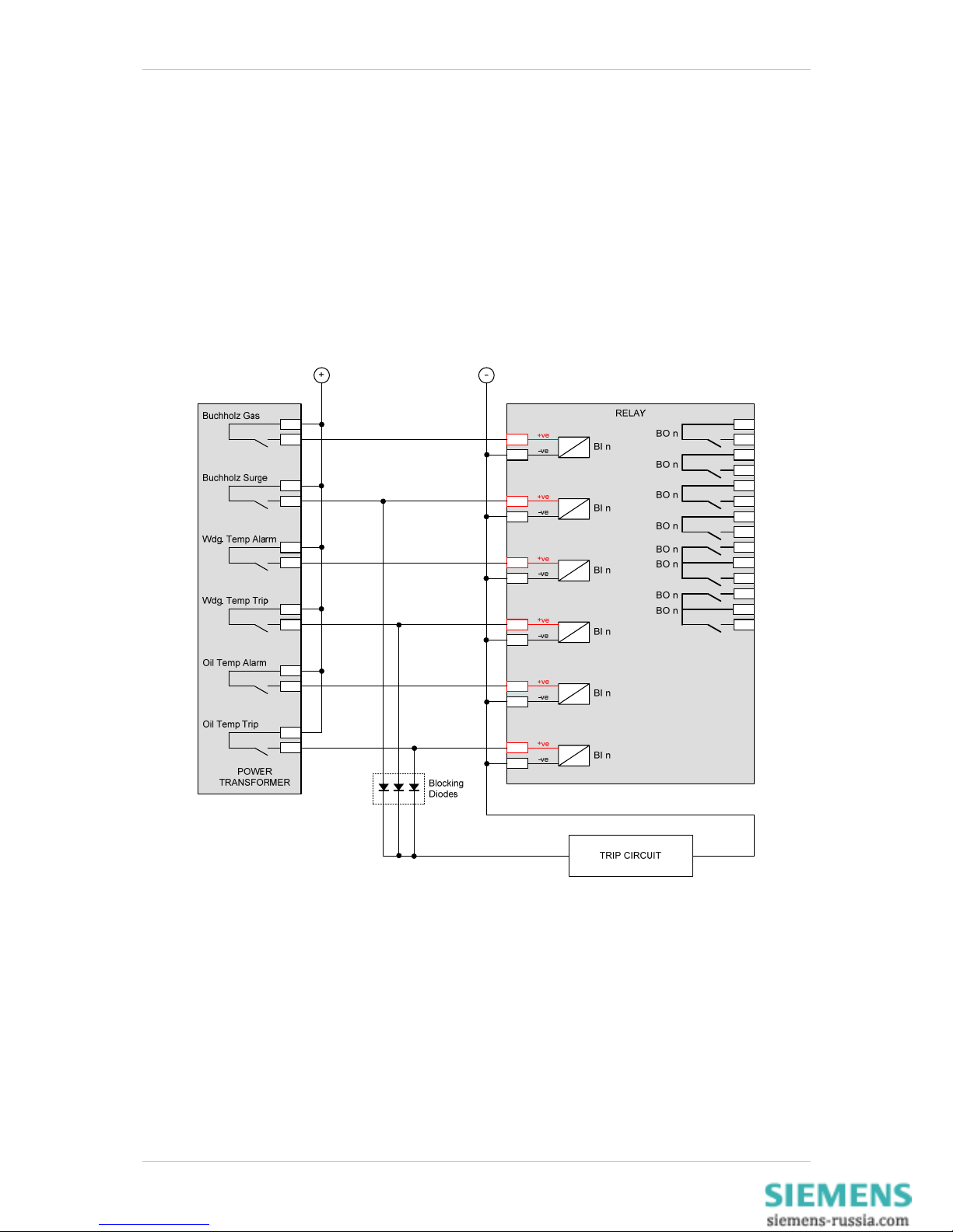
Alarm and Tripping Inputs
A common use of binary inputs is to provide indication of alarm or fault conditions e.g. transformer Buchholz Gas
or Buchholz Surge conditions. The Binary Inputs are mapped to LED(s), waveform storage trigger and binary
outputs. Note that transformer outputs which require high speed tripping, such as a Buchholz Surge, should be
wired to a binary input to provide LED indication and also have a parallel connection wired to directly trip the
circuit via a blocking diode, see fig. 1.2-1:
Figure 1.2-1 Example of Transformer Alarm and Trip Wiring
Page 6 of 40 ©2011 Siemens Protection Devices Limited

7SR210 & 7SR220 Applications Guide
The Effects of Capacitance Current
The binary inputs have a low minimum operate current and may be set for instantaneous operation. Consideration
should be given to the likelihood of mal-operation due to capacitance current. Capacitance current can flow
through the BI for example if an earth fault occurs on the dc circuits associated with the relay. The binary inputs
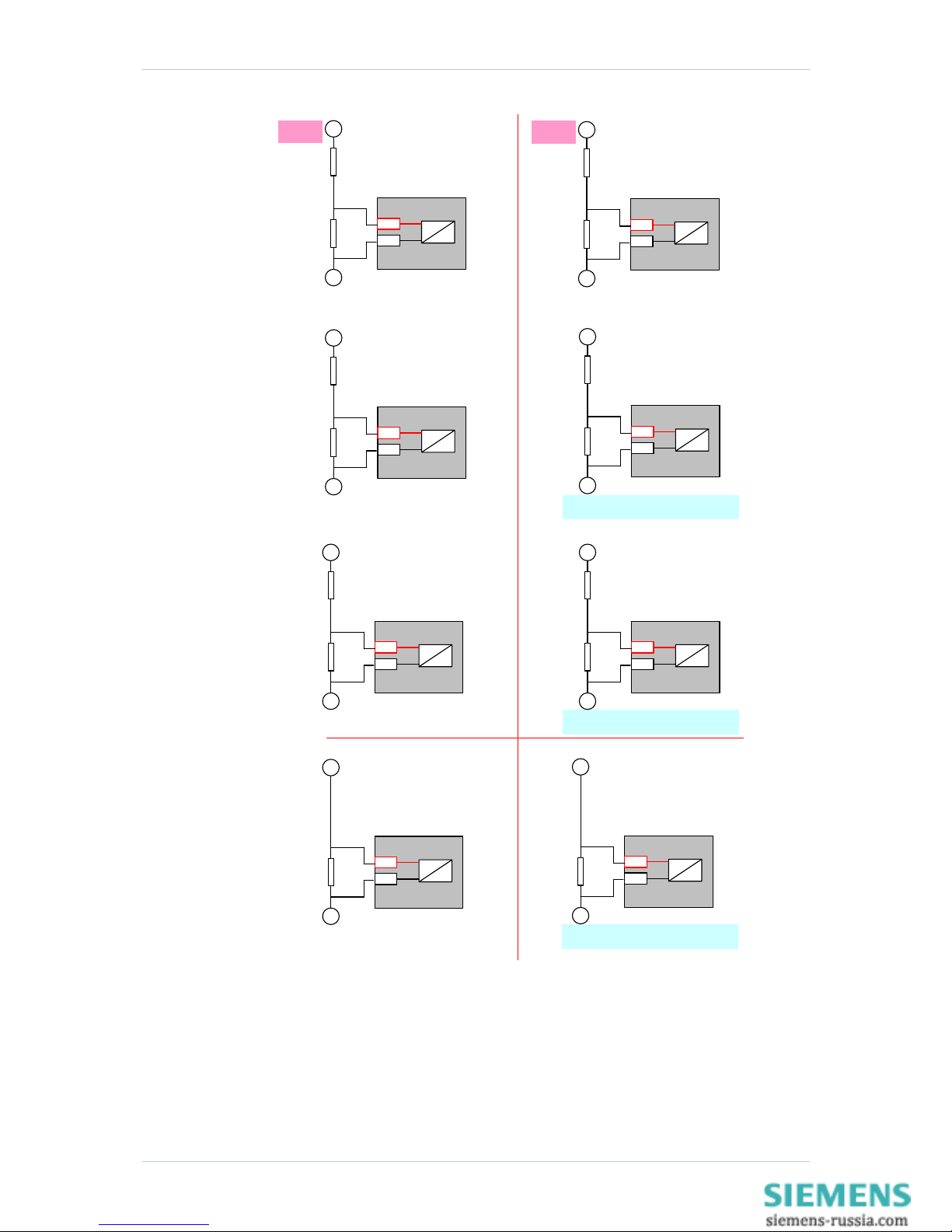
will be less likely to mal-operate if they:
1 Have both the positive and negative switched (double-pole switched).
2 Do not have extensive external wiring associated with them e.g. if the wiring is confined to the
relay room.
Where a binary input is both used to influence a control function (e.g. provide a tripping function) and it is
considered to be susceptible to mal-operation the external circuitry can be modified to provide immunity to such
disturbances, see fig 1.2-2.
AC Rejection
The default pick-up time delay of 20ms provides immunity to ac current e.g. induced from cross site wiring.
©2011 Siemens Protection Devices Limited Page 7 of 40
7SR210 & 7SR220 Applications Guide
Page 8 of 40 ©2011 Siemens Protection Devices Limited
2K0
BI (19 V)
ESI-1
30 V DC Nominal
(24 V to 37.5 V Operative)
I
OP
> 10 mA
470
1K5
48 V DC Nominal
(37.5 V to 60 V Operative)
I
OP
> 10 mA
1K6
1K5
110 V DC Nominal
(87.5 V to 137.5 V
Operative)
I
OP
> 25 mA
560
ESI-2
30 V DC Nominal
(24 V to 37.5 V Operative)
I
OP
> 20 mA
220
820
48 V DC Nominal
(37.5 V to 60 V Operative)
I
OP
> 20 mA
820
820
110 V DC Nominal
(87.5 V to 137.5 V
Operative)
I
OP
> 50 mA
1K2
330
BI DTL = 10 ms
(10 µF, 60 V Capacitance discharge)
BI DTL = 10 ms
(10 µF, 150 V Capacitance discharge)
BI (19 V)
BI (19 V)
BI (19 V)
BI (19 V)
BI (19 V)
+
-
+
+
+
+
+
-
-
-
-
-
Resistor power ratings: 30 V DC Nominal >3 W
48 V DC Nominal >3 W
110 V DC Nominal >10 W (ESI-1)
110 V DC Nominal >20 W (ESI-2)
Resistors must be wired with crimped connections as they may run hot
110 V DC Nominal
(87.5 V to 137.5 V
Operative)
I
OP
> 25 mA
2K7
110 V DC Nominal
(87.5 V to 137.5 V
Operative)
I
OP
> 50 mA
1K3
BI DTL = 10 ms
(10 µF, 150 V Capacitance discharge)
BI (88 V)
BI (88 V)
+
+
-
-
Figure 1.2-2 – Binary Input Configurations Providing Compliance with EATS 48-4 Classes ESI 1 and ESI 2
7SR210 & 7SR220 Applications Guide
1.3 Binary Outputs
Binary Outputs are mapped to output functions by means of settings. These could be used to bring out such
digital signals as trips, a general pick-up, plant control signals etc.
All Binary Outputs are Trip rated
Each can be defined as Self or Hand Reset. Self-reset contacts are applicable to most protection applications.
Hand-reset contacts are used where the output must remain active until the user expressly clears it e.g. in a
control scheme where the output must remain active until some external feature has correctly processed it.
Case contacts 26 and 27 will automatically short-circuit when the relay is withdrawn from the case. This can be
used to provide an alarm that the Relay is out of service.
Notes on Self Reset Outputs
With a failed breaker condition the relay may remain operated until current flow in the primary system is
interrupted by an upstream device. The relay will then reset and attempt to interrupt trip coil current flowing
through an output contact. Where this level is above the break rating of the output contact an auxiliary relay with
heavy-duty contacts should be utilised.
1.4 LEDs
Output-function LEDs are mapped to output functions by means of settings. These could be used to display such
digital signals as trips, a general pick-up, plant control signals etc.
User Defined Function Key LEDs are used to indicate the status of Function Key operation. These do not relate
directly to the operation of the Function Key but rather to its consequences. If a Function Key is depressed to
close a Circuit-Breaker, the associated LED would show the status of the Circuit-Breaker closed Binary Input.
Each LED can be defined as Self or Hand Reset. Hand reset LEDs are used where the user is required to
expressly acknowledge the change in status e.g. critical operations such as trips or system failures. Self-reset
LEDs are used to display features which routinely change state, such as Circuit-Breaker open or close.
The status of hand reset LEDs is retained in capacitor-backed memory in the event of supply loss.
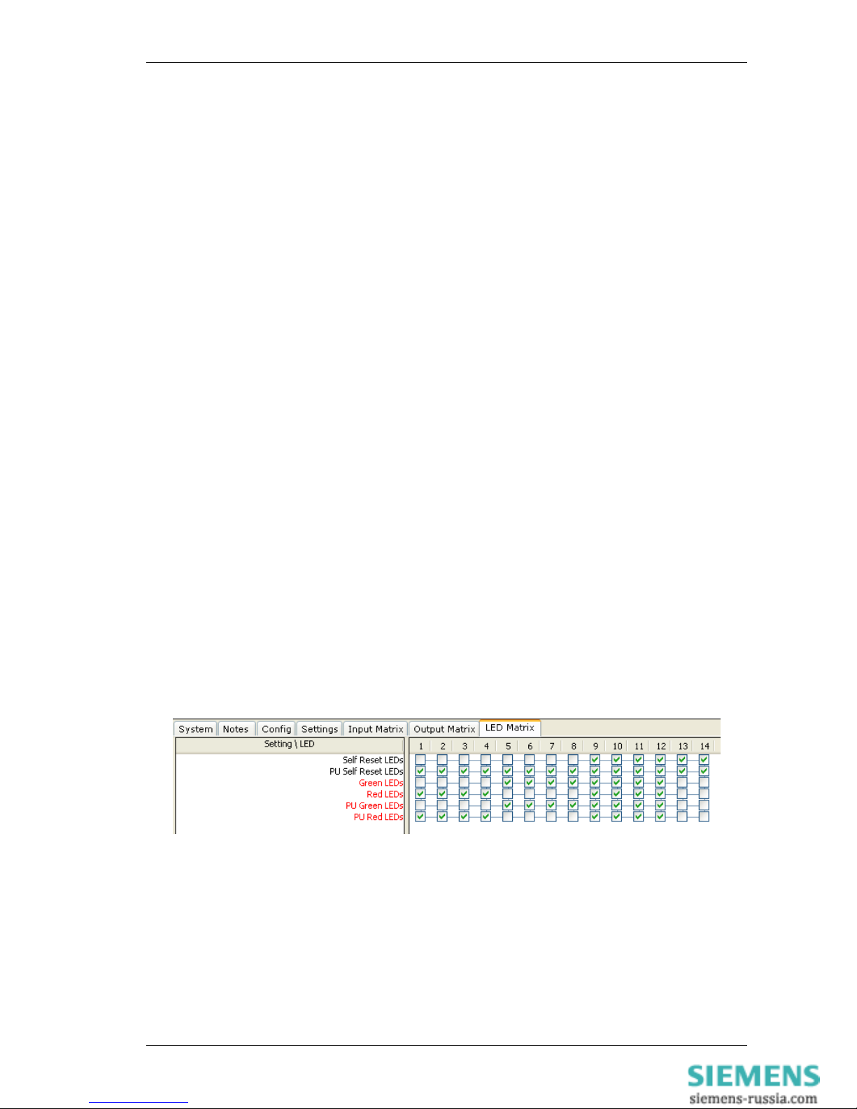
Each LED can be assigned as red, yellow or green in colour. There are two methods for doing this: -
1) In the LED Matrix tab, to assign the LED as a red colour select a box on the red row. To assign the
LED as a green colour select a box on the green row. To assign the LED as a yellow colour, select
boxes on both the red and green rows.
NB: If there are no boxes selected the LED will not illuminate.
Figure 1.4-1 LED configuration via the LED Matrix tab
©2011 Siemens Protection Devices Limited Page 9 of 40
7SR210 & 7SR220 Applications Guide
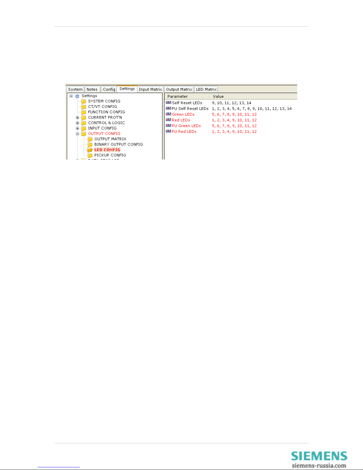
In the OUTPUT CONFIG\LED CONFIG menu in the Settings tab, to assign the required LED as a
particular colour, either red or green, type the LED number in the appropriate row. To assign the
required LED as a yellow colour, type the LED number in both red and green rows.
NB: If a LED number is not assigned that particular LED will not illuminate.
Figure 1.4-2 LED configuration via the Settings \ OUTPUT CONFIG \ LED CONFIG menu
Page 10 of 40 ©2011 Siemens Protection Devices Limited
7SR210 & 7SR220 Applications Guide
Section 2: Protection Functions
2.1 Time delayed overcurrent (51/51G/51N)
The 51-n characteristic element provides a number of time/current operate characteristics. The element can be
defined as either an Inverse Definite Minimum Time Lag (IDMTL) or Definite Time Lag (DTL) characteristic. If an
IDMTL characteristic is required, then IEC, ANSI/IEEE and a number of manufacturer specific curves are
supported.
IDMTL characteristics are defined as “Inverse” because their tripping times are inversely proportional to the Fault
Current being measured. This makes them particularly suitable to grading studies where it is important that only
the Relay(s) closest to the fault operate. Discrimination can be achieved with minimised operating times.
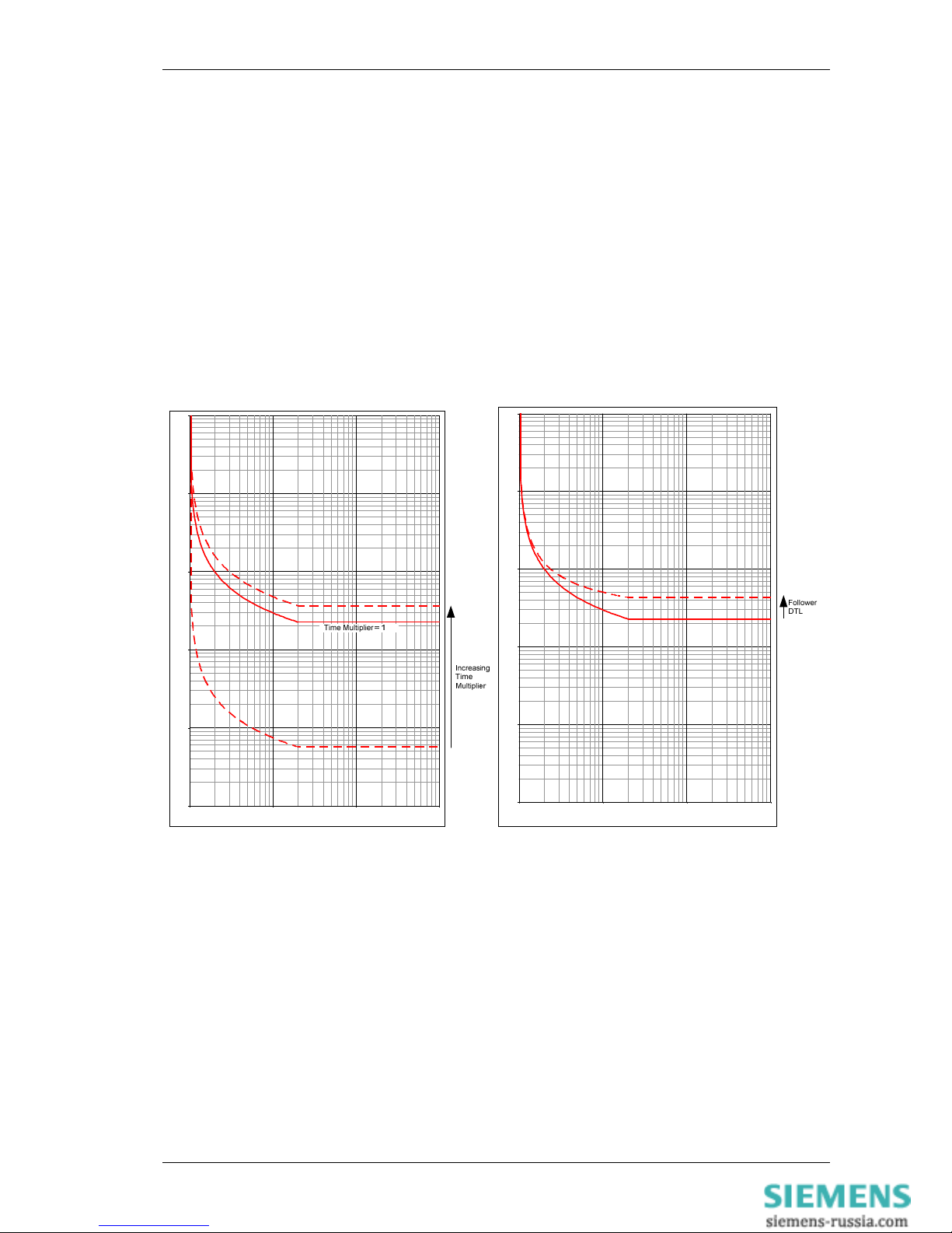
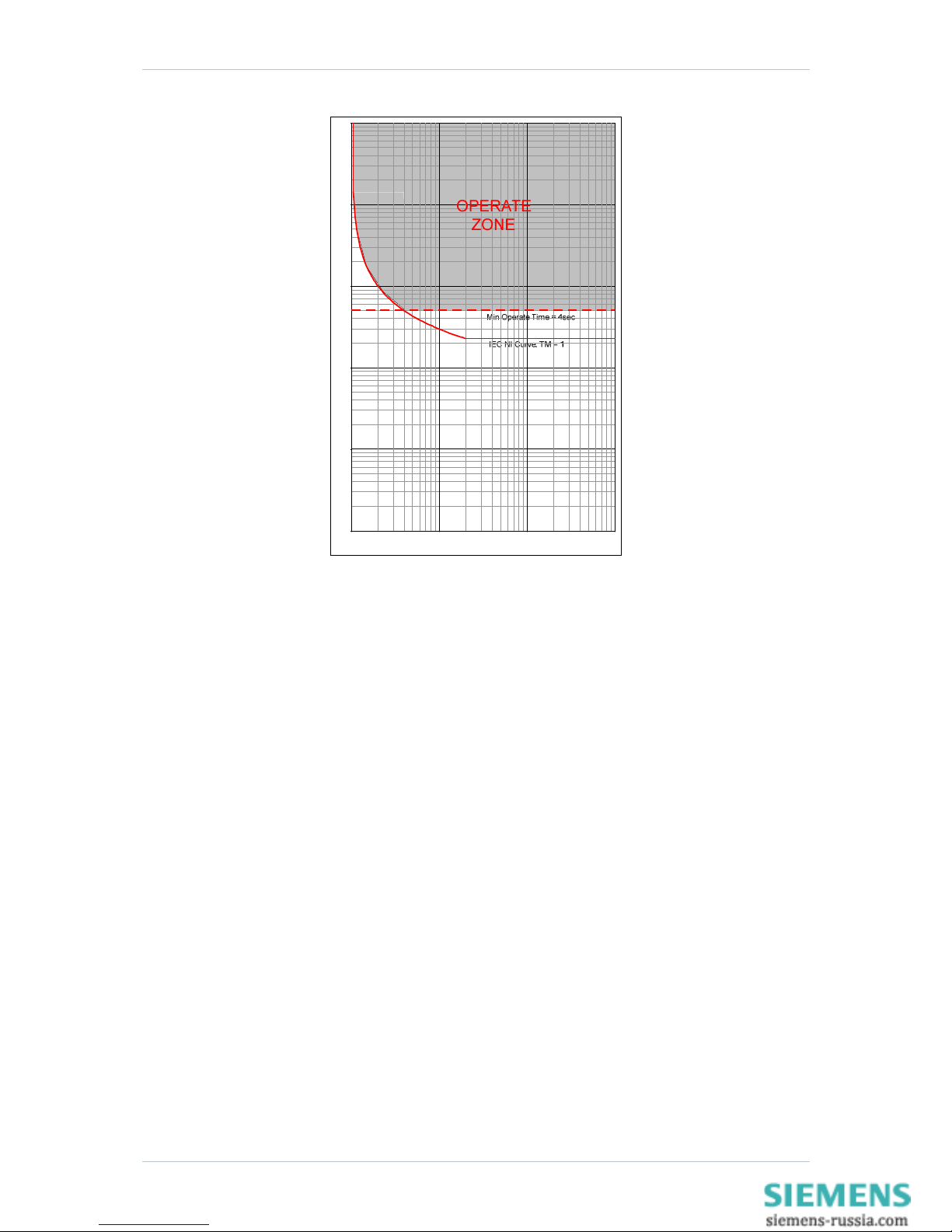
To optimise the grading capability of the relay additional time multiplier, ‘Follower DTL’ (Fig. 2.1-1) or ‘Minimum
Operate Time’ (Fig. 2.1-2) settings can be applied.
0.01
0.10
1.00
10.00
100.00
1000.00
1 10 100 1000
Current (x Is)
Operating Time (Sec onds
)
0.01
0.10
1.00
10.00
100.00
1000.00
1 10 100 1000
Current (x Is)
Operating Time (Seconds
)
Figure 2.1-1 IEC NI Curve with Time Multiplier and Follower DTL Applied
©2011 Siemens Protection Devices Limited Page 11 of 40
7SR210 & 7SR220 Applications Guide
0.01
0.10
1.00
10.00
100.00
1000.00
1 10 100 1000
Current (x Is)
Operating Time (Seconds
)
Figure 2.1-2 IEC NI Curve with Minimum Operate Time Setting Applied
To increase sensitivity, dedicated Earth fault elements are used. There should be little or no current flowing to
earth in a healthy system so such relays can be given far lower pick-up levels than relays which detect excess
current ( > load current) in each phase conductor. Such dedicated earth fault relays are important where the fault
path to earth is a high-resistance one (such as in highly arid areas) or where the system uses high values of
earthing resistor / reactance and the fault current detected in the phase conductors will be limited.
2.1.1 Selection of Overcurrent Characteristics
Each pole has two independent over-current characteristics. Where required the two curves can be used:
To produce a composite curve
To provide a two stage tripping scheme
Where one curve is to be directionalised in the forward direction the other in the reverse direction.
The characteristic curve shape is selected to be the same type as the other relays on the same circuit or to grade
with items of plant e.g. fuses or earthing resistors.
The application of IDMTL characteristic is summarised in the following table:
Page 12 of 40 ©2011 Siemens Protection Devices Limited
 Loading...