

Page 1
Drive Technology \ Drive Automation \ System Integration \ Services
Operating Instructions
MOVIMOT
®
MM..D
With DRS/DRE/DRP AC Motor
Edition 12/2010 17000017 / EN
Page 2

SEW-EURODRIVE—Driving the world
Page 3

Contents
Contents
1 General Information ............................................................................................ 6
1.1 How to use this documentation................................................................... 6
1.2 Structure of the safety notes ....................................................................... 6
1.3 Rights to claim under limited warranty ........................................................ 7
1.4 Exclusion of liability..................................................................................... 7
1.5 Copyright..................................................................................................... 7
1.6 Product names and trademarks.................................................................. 7
2 Safety Notes ........................................................................................................ 8
2.1 Preliminary information ............................................................................... 8
2.2 General information .................................................................................... 8
2.3 Target group ............................................................................................... 8
2.4 Designated use ........................................................................................... 9
2.5 Other applicable documentation ................................................................. 9
2.6 Transportation, storage............................................................................. 10
2.7 Installation................................................................................................. 10
2.8 Electrical connection ................................................................................. 10
2.9 Safe disconnection.................................................................................... 10
2.10 Operation .................................................................................................. 11
3 Unit Design ........................................................................................................ 12
3.1 MOVIMOT
3.2 MOVIMOT
3.3 Type designation of MOVIMOT
3.4 Type designation of MOVIMOT
3.5 Type designation of the variant "mounted close to the motor".................. 17
4 Mechanical Installation..................................................................................... 18
4.1 MOVIMOT
4.2 Installation of MOVIMOT
4.3 Installation of the MOVIMOT
4.4 Tightening torques .................................................................................... 28
5 Electrical Installation ........................................................................................ 30
5.1 Installation instructions.............................................................................. 30
5.2 Connection of the MOVIMOT
5.3 MOVIMOT
5.4 Connection between MOVIMOT
when mounted close to the motor............................................................. 38
5.5 Connection of the MOVIMOT
5.6 Connection of RS-485 bus master............................................................ 53
5.7 Connecting the DBG keypad .................................................................... 54
5.8 PC connection........................................................................................... 55
®
drive...................................................................................... 12
®
inverter.................................................................................. 13
®
drive...................................................... 15
®
inverter ................................................. 16
®
gearmotor installation ........................................................... 18
®
options............................................................ 20
®
inverter close to the motor........................ 27
®
drive......................................................... 36
®
plug connectors .................................................................... 37
®
and motor
®
options .................................................... 42
Operating Instructions – MOVIMOT® MM..D with DRS/DRE/DRP AC Motor
3
Page 4

Contents
6 "Easy" Startup................................................................................................... 56
6.1 Overview ................................................................................................... 56
6.2 Important notes on startup ........................................................................ 57
6.3 Requirements............................................................................................ 58
6.4 Description of control elements................................................................. 58
6.5 Description of the DIP switches S1........................................................... 61
6.6 Description of DIP switches S2................................................................. 63
6.7 Selectable additional functions MM..D-503-00 ......................................... 67
6.8 Startup with binary control ........................................................................ 91
6.9 Startup with options MBG11A or MLG..A ................................................. 93
6.10 Startup with MWA21A option .................................................................... 95
6.11 Startup with MWF11A option .................................................................... 98
6.12 Supplementary notes for installation close to the motor ........................ 100
7 "Easy" Startup with RS-485 Interface/Fieldbus............................................ 103
7.1 Important notes on startup ...................................................................... 103
7.2 Requirements.......................................................................................... 104
7.3 Startup procedure ................................................................................... 104
7.4 Coding of process data ........................................................................... 106
7.5 Function with RS-485 master.................................................................. 111
8 "Expert" Startup with Parameter Function ................................................... 116
8.1 Important notes on startup ...................................................................... 116
8.2 Requirements.......................................................................................... 117
8.3 MOVITOOLS
8.4 Startup and function expansion with individual parameters.................... 119
8.5 Startup and configuration with a central controller and MQP.................. 122
8.6 Startup by transferring the set of parameters ......................................... 123
8.7 Parameter list.......................................................................................... 125
8.8 Parameter description............................................................................. 131
9 Operation ......................................................................................................... 151
9.1 Operating display .................................................................................... 151
9.2 Drive ID module ...................................................................................... 152
9.3 Keypads .................................................................................................. 153
9.4 MWA21A setpoint converter ................................................................... 154
9.5 MWF11A setpoint converter ................................................................... 155
9.6 MOVIMOT
9.7 DBG keypad............................................................................................ 164
®
MotionStudio................................................................... 117
®
manual operation with MOVITOOLS® MotionStudio .......... 160
4
Operating Instructions – MOVIMOT® MM..D with DRS/DRE/DRP AC Motor
Page 5

Contents
10 Service ............................................................................................................. 172
10.1 Status and error display .......................................................................... 172
10.2 Inspection/maintenance .......................................................................... 176
10.3 Diagnostics with MWF11A option ........................................................... 177
10.4 Unit replacement..................................................................................... 178
10.5 Rotating the connection box ................................................................... 180
10.6 SEW Service........................................................................................... 182
10.7 Shut down ............................................................................................... 182
10.8 Storage ................................................................................................... 183
10.9 Extended storage.................................................................................... 183
10.10 Disposal .................................................................................................. 183
11 Technical Data................................................................................................. 184
11.1 Motor with operating point 400 V / 50 Hz or 400 V / 100 Hz................... 184
11.2 Motor with operating point 460 V / 60 Hz................................................ 186
11.3 Motor with operating point 230 V / 60 Hz................................................ 188
11.4 Technical data of options & accessories................................................. 190
11.5 Work done, working air gap and braking torque of the brake ................. 195
11.6 Braking torque assignment ..................................................................... 195
11.7 Integrated RS-485 interface.................................................................... 196
11.8 Diagnostics interface............................................................................... 196
11.9 Assignment of internal braking resistors ................................................. 196
11.10 Assignment of external braking resistors ................................................ 197
11.11 Resistance and assignment of the brake coil ......................................... 197
11.12 Assignment of the Drive-ID module ........................................................ 198
12 Declaration of Conformity .............................................................................. 199
13 Address List .................................................................................................... 200
Index................................................................................................................. 210
Operating Instructions – MOVIMOT® MM..D with DRS/DRE/DRP AC Motor
5
Page 6
1
General Information
How to use this documentation
1 General Information
1.1 How to use this documentation
The documentation is an integral part of the product and contains important information
on operation and service. The documentation is written for all employees who assemble,
install, startup, and service this product.
The documentation must be accessible and legible. Make sure that persons responsible
for the system and its operation, as well as persons who work independently on the unit,
have read through the documentation carefully and understood it. If you are unclear
about any of the information in this documentation, or if you require further information,
contact SEW-EURODRIVE.
1.2 Structure of the safety notes
1.2.1 Meaning of the signal words
The following table shows the grading and meaning of the signal words for safety notes,
notes on potential risks of damage to property, and other notes.
Signal word Meaning Consequences if disregarded
DANGER Imminent danger Severe or fatal injuries
WARNING Possible dangerous situation Severe or fatal injuries
CAUTION Possible dangerous situation Minor injuries
NOTICE Possible damage to property Damage to the drive system or its envi-
INFORMATION Useful information or tip: Simpli-
fies the handling of the drive
system.
1.2.2 Structure of the section-related safety notes
Section safety notes do not apply to a specific action, but to several actions pertaining
to one subject. The used symbols indicate either a general or a specific hazard.
This is the formal structure of a section safety note:
SIGNAL WORD
Type and source of danger.
Possible consequence(s) if disregarded.
• Measure(s) to prevent the danger.
1.2.3 Structure of the embedded safety notes
Embedded safety notes are directly integrated in the instructions just before the description of the dangerous action.
ronment
This is the formal structure of an embedded safety note:
• SIGNAL WORD Nature and source of hazard.
Possible consequence(s) if disregarded.
– Measure(s) to prevent the danger.
6
Operating Instructions – MOVIMOT® MM..D with DRS/DRE/DRP AC Motor
Page 7

Rights to claim under limited warranty
1.3 Rights to claim under limited warranty
A requirement of fault-free operation and fulfillment of any rights to claim under limited
warranty is that you adhere to the information in the documentation. Read the documentation before you start working with the unit!
1.4 Exclusion of liability
General Information
1
You must comply with the information contained in this documentation to ensure safe
operation of MOVIMOT
formance features. SEW-EURODRIVE assumes no liability for injury to persons or damage to equipment or property resulting from non-observance of these operating instructions. In such cases, any liability for defects is excluded.
®
1.5 Copyright
© 2010 – SEW-EURODRIVE. All rights reserved.
Unauthorized duplication, modification, distribution or any other use of the whole or any
part of this documentation is strictly prohibited.
1.6 Product names and trademarks
All brands and product names in this documentation are trademarks or registered trademarks of their respective titleholders.
and to achieve the specified product characteristics and per-
Operating Instructions – MOVIMOT® MM..D with DRS/DRE/DRP AC Motor
7
Page 8

2
Safety Notes
Preliminary information
2 Safety Notes
The following basic safety notes must be read carefully to prevent injury to persons and
damage to property. The operator must ensure that the basic safety notes are read and
adhered to. Make sure that persons responsible for the plant and its operation, as well
as persons who work independently on the unit, have read through the operating instructions carefully and understood them. If you are unclear about any of the information in
this documentation or if you require further information, please contact SEWEURODRIVE.
2.1 Preliminary information
The following safety notes are primarily concerned with the use of MOVIMOT® drives.
If you use other SEW components, also refer to the safety notes for the respective components in the corresponding documentation.
Please also observe the supplementary safety notes in the individual chapters of this
documentation.
2.2 General information
Never install or start up damaged products. Submit a complaint to the shipping company
immediately in the event of damage.
During operation, MOVIMOT
as well as hot surfaces, depending on their enclosure.
Removing covers without authorization, improper use as well as incorrect installation or
operation may result in severe injuries to persons or damage to property. Refer to the
documentation for additional information.
2.3 Target group
Only qualified personnel is authorized to install, startup or service the units or correct
unit faults (observing IEC 60364 and/or CENELEC HD 384 or DIN VDE 0100 and IEC
60664 or DIN VDE 0110 as well as national accident prevention guidelines).
Qualified personnel in the context of these basic safety notes are persons familiar with
installation, assembly, startup and operation of the product who possess the necessary
qualifications.
Any activities regarding transportation, storage, operation, and disposal must be carried
out by persons who have been instructed appropriately.
®
drives can have live, bare and movable or rotating parts
8
Operating Instructions – MOVIMOT® MM..D with DRS/DRE/DRP AC Motor
Page 9

2.4 Designated use
MOVIMOT® inverters are components intended for installation in electrical systems or
machines.
In case of installation in machines, startup of MOVIMOT
nated operation) is prohibited until it is determined that the machine meets the requirements stipulated in the Machinery Directive 2006/42/EC.
Startup (i.e. the start of designated use) is only permitted under observance of the EMC
directive 2004/108/EC.
MOVIMOT
EC. The standards given in the declaration of conformity are used for the MOVIMOT
inverter.
You must observe the technical data and information on the connection requirements
as provided on the nameplate and in the documentation.
2.4.1 Safety functions
The MOVIMOT
described and expressly permitted.
Safety Notes
Designated use
®
inverters (i.e. start of desig-
®
inverters comply with the regulations of the Low Voltage Directive 2006/95/
®
inverter may not perform safety functions unless these functions are
2
®
2.4.2 Hoist applications
MOVIMOT
sec. "Additional function 9" (page 78).
MOVIMOT
®
inverters are suitable for hoist applications to a limited degree only, see
®
inverters are not designed for use as a safety device in hoist applications.
2.5 Other applicable documentation
Note also the following documentation:
•"MOVIMOT
• "DR.71-225, 315 AC Motors" operating instructions
• Operating instructions for the gear unit (only for MOVIMOT
You can download or order these publications on the Internet (http://www.sew-euro-
drive.de, under the heading "Documentation").
®
Gearmotors" catalog
®
gearmotors)
Operating Instructions – MOVIMOT® MM..D with DRS/DRE/DRP AC Motor
9
Page 10

2
Safety Notes
Transportation, storage
2.6 Transportation, storage
You must observe the notes on transportation, storage and proper handling. Comply
with the requirements for climatic conditions stated in chapter "Technical Data". Tighten
installed eyebolts securely. They are designed for the weight of the MOVIMOT
Do not attach any additional loads. Use suitable, sufficiently rated handling equipment
(e.g. rope guides) if required.
2.7 Installation
The units must be installed and cooled according to the regulations and specifications
in the corresponding documentation.
Protect the MOVIMOT
The following applications are prohibited unless the unit is explicitly designed for such
use:
• Use in potentially explosive atmospheres.
• Use in areas exposed to harmful oils, acids, gases, vapors, dust, radiation, etc.
• Use in non-stationary applications with strong mechanical oscillation and impact
®
inverters from improper strain.
loads; see chapter "Technical Data".
®
drive.
2.8 Electrical connection
Observe the applicable national accident prevention guidelines when working on live
MOVIMOT
Perform electrical installation according to the pertinent regulations (e.g. cable cross
sections, fusing, protective conductor connection). For any additional information, refer
to the applicable documentation.
For notes on EMC compliant installation, such as shielding, grounding, arrangement of
filters and routing of lines, refer to chapter "Installation instructions". The manufacturer
of the system or machine is responsible for maintaining the limits established by EMC
legislation.
Protective measures and protection devices must comply with the regulations in force
(e.g. EN 60204 or EN 61800-5-1).
A voltage test according to EN 61800-5-1:2007 chapter 5.2.3.2 is required for the
MOVIMOT
®
®
2.9 Safe disconnection
MOVIMOT® inverters meet all requirements for safe disconnection of power and electronic connections in accordance with EN 61800-5-1. All connected circuits must also
satisfy the requirements for safe disconnection.
drive inverters (e.g. BGV A3).
drives prior to startup in order to ensure the insulation.
10
Operating Instructions – MOVIMOT® MM..D with DRS/DRE/DRP AC Motor
Page 11

2.10 Operation
Safety Notes
Operation
Systems with integrated MOVIMOT® inverters must be equipped with additional monitoring and protection devices according to the applicable safety guidelines, such as the
law governing technical equipment, accident prevention regulations, etc. Additional protective measures may be necessary for applications with increased potential risk.
Do not touch live components and power connections immediately after separation of
the MOVIMOT
charged capacitors. Wait at least for 1 minute after having switched off the supply voltage.
As soon as supply voltages are present at the MOVIMOT
must be closed (i.e. the MOVIMOT
brid cable must be connected).
The fact that the status LED and other display elements are no longer illuminated does
not indicate that the unit has been disconnected from the supply system and no longer
carries any voltage.
Mechanical blocking or internal safety functions of the unit can cause a motor standstill.
Eliminating the cause of the problem or performing a reset may result in the drive restarting automatically. If, for safety reasons, this is not permitted for the driven machine,
disconnect the unit from the supply system before correcting the error.
Caution: Danger of burns: The surface temperature of the MOVIMOT
ternal options, e.g. the heat sink of the braking resistor, can exceed 60 °C during operation!
®
inverter from the supply voltage because there may still be some
®
®
inverter and, if applicable, the connector of the hy-
inverter, the connection box
®
drive and of ex-
2
Operating Instructions – MOVIMOT® MM..D with DRS/DRE/DRP AC Motor
11
Page 12
3
3 Unit Design
3.1 MOVIMOT® drive
Unit Design
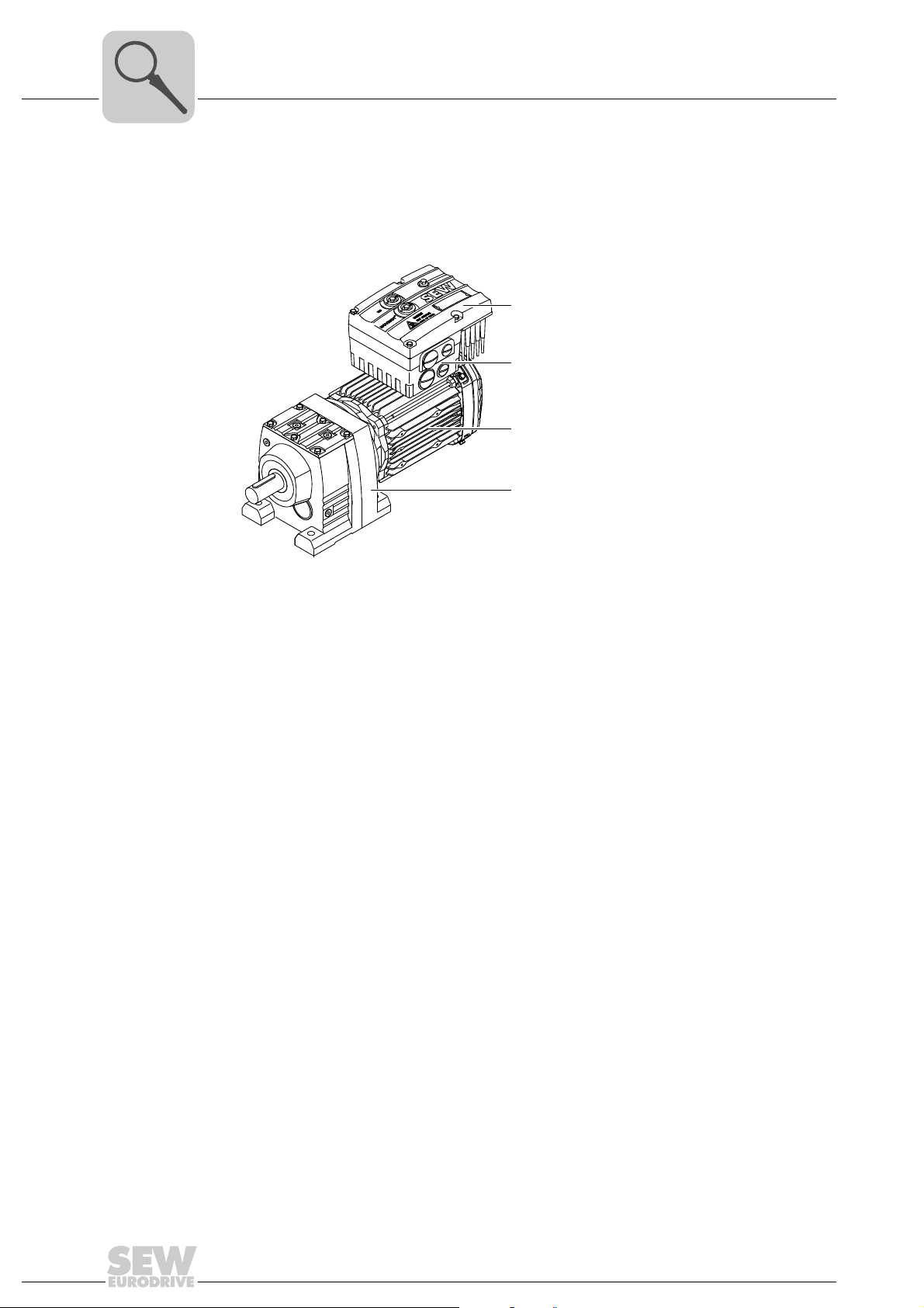
MOVIMOT® drive
The following figure shows a MOVIMOT® drive with helical gear unit:
[1]
[2]
[3]
[4]
[1] MOVIMOT® inverter
[2] Connection box
[3] Motor
[4] Helical gear unit
A MOVIMOT
• MOVIMOT
– Mounted on the motor (see example above)
– or mounted close to the motor
• Motor (see motor operating instructions)
• Gear unit (optional, see gear unit operating instructions)
®
drive is a combination of:
®
inverter
3531634827
12
Operating Instructions – MOVIMOT® MM..D with DRS/DRE/DRP AC Motor
Page 13
3.2 MOVIMOT® inverter
[7][6][5] [7][11] [13] [15]
0 1 2 0 1 2
[14] [16][5] [12] [17] [18][8] [9] [10]
[4]
[3][1] [2]
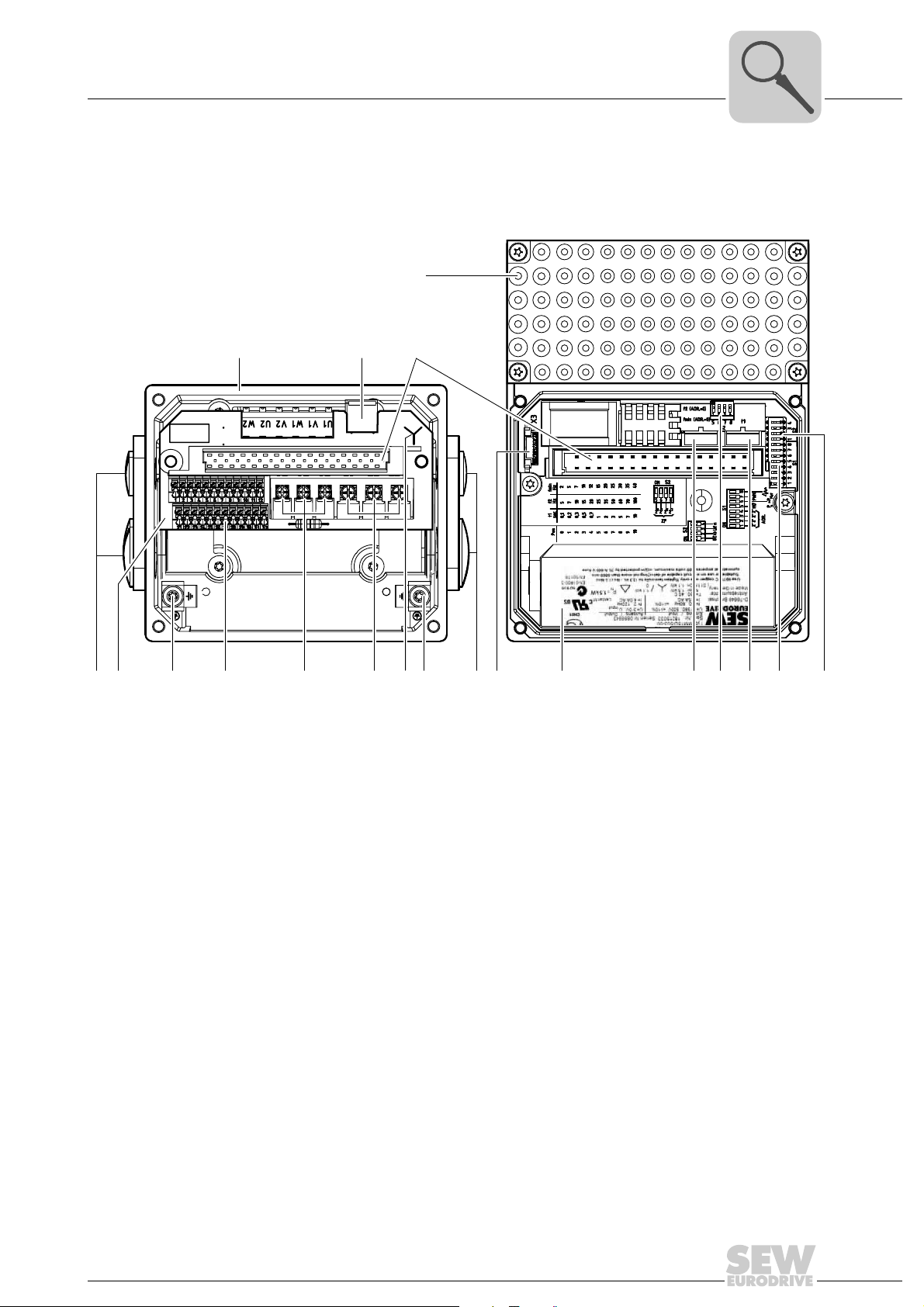
The following figure shows the connection box and the MOVIMOT® inverter:
Unit Design
MOVIMOT® inverter
3
[1] Connection box
[2] X10: Plug connector for BEM option
[3] Plug connector for MOVIMOT
[4] MOVIMOT
[5] Cable glands
[6] Connection unit with terminals
[7] Screw for PE connection
[8] X5, X6: Electronics terminal strips
[9] X1: Connection for brake coil (motors with brake) or braking resistor (motors without brake)
[10] X1: Supply system connection L1, L2, L3
[11] Connection type identification
[12] Drive-ID module
[13] Nameplate of the MOVIMOT
[14] Setpoint switch f2 (green)
[15] DIP switches S2/5 – S2/8
[16] Switch t1 for integrator ramp (white)
[17] DIP switches S1/1 – S1/8
[18] DIP switches S2/1 – S2/4
®
inverter with heat sink
®
inverter
®
inverter
615683595
Operating Instructions – MOVIMOT® MM..D with DRS/DRE/DRP AC Motor
13
Page 14
3
[4]
[3]
[2]
[1]
Unit Design
MOVIMOT® inverter
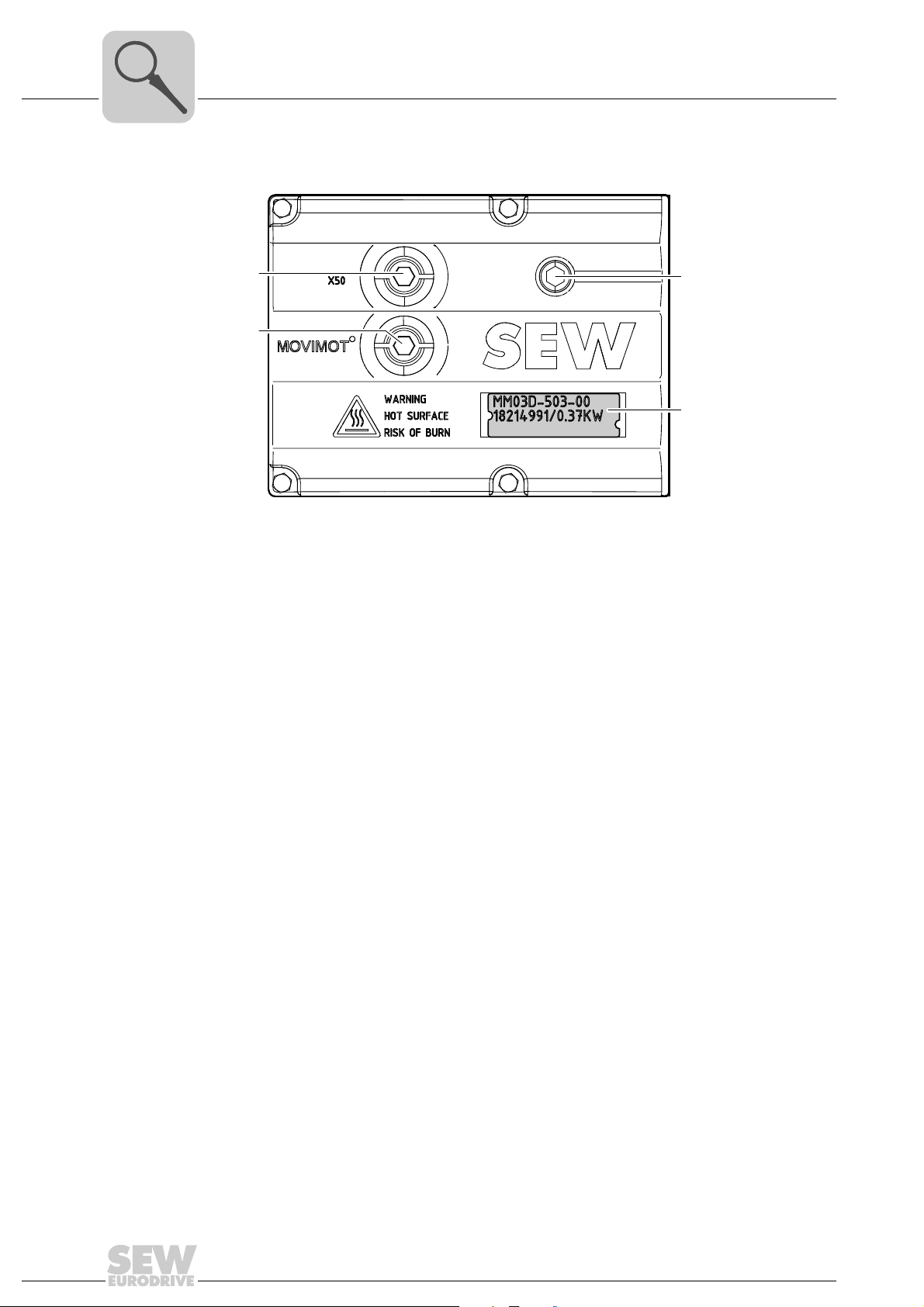
The following figure shows the top of the MOVIMOT® inverter:
514402955
[1] X50: Diagnostics interface with screw plug
[2] Setpoint potentiometer f1 with screw plug
[3] Status LED
[4] Unit identification
14
Operating Instructions – MOVIMOT® MM..D with DRS/DRE/DRP AC Motor
Page 15
Type designation of MOVIMOT® drive
3.3 Type designation of MOVIMOT® drive
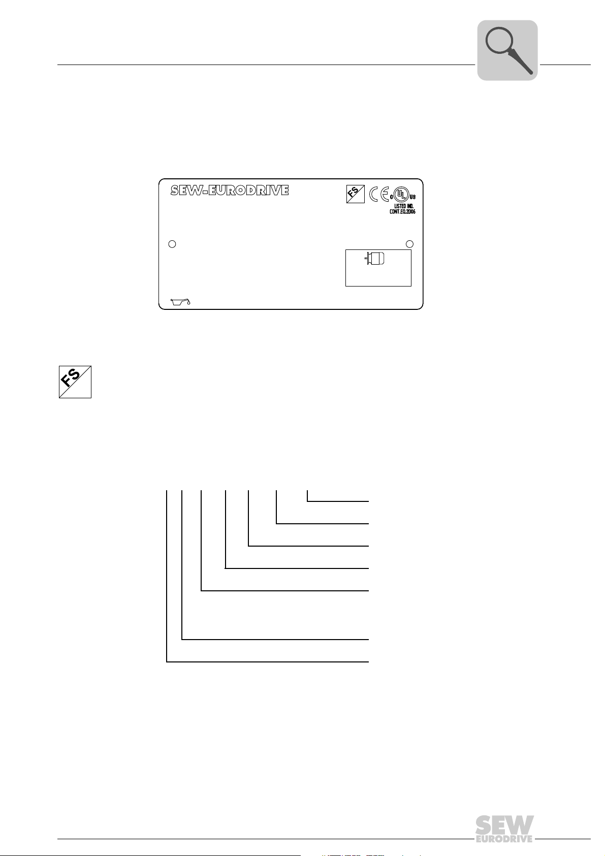
3.3.1 Nameplate
The following figure gives an example of a nameplate of a MOVIMOT
plate is attached to the motor.
Unit Design
®
drive. The name-
3
76646 Bruchsal/Germany
RF47DRE90L4BE2/MM15/MO
01.300123457.0002.06
380-500
V
1.5
kW
16.22 166 54
I
M1
IM
220..240
BR
V
CLP CC VGB220 0.65I
Nm
Nm
Hz
13
Hz 50-60
50
kg
IP
r/min
M.L.
31
A
1400/86 1:5
02
01
-20...40
°C
Iso.Kl.
CT
kW
eff %
Made in Germany
155(F)3.5
TEFC
3~
1.5 50
Hz
85.2
1883410
FS logo The logos at the top of the nameplate are only there if:
• the motor is manufactured accordingly,
01
• and contains at least one safety-rated component.
The FS logo on the nameplate is based on the combination of safety-related components that is installed.
3.3.2 Type designation
The following table shows the type designation of the MOVIMOT
RF 47 DRE 90L4 BE/MM15/MO
Additional feature: inverter
9007199774918155
®
drive:
1)
MOVIMOT® inverter
Optional design motor (brake)
Size, number of poles on motor
Motor series
DRS = DRS motor
DRE = DRE motor
DRP = DRP motor
Gear unit size
Gear unit series
1) The nameplate only displays options installed at the factory.
The available variants are listed in the "MOVIMOT
®
Gearmotors" catalog.
Operating Instructions – MOVIMOT® MM..D with DRS/DRE/DRP AC Motor
15
Page 16
3
Status:
10 12 -- A -- -- 10 10 12
02 / 08 444
Type :
MM15D-503-00
P# : 18215033
Eingang / Input
U
f
I
T -30 . . . +40°C
I3.5A AC 4.0A AC
f50 ... 60Hz
D-76646 Bruchsal
MOVIMOT
Antriebsumrichter
P-Motor 1.5kW / 2.0HP
Drive Inverter
Use 60/75°C copper wire only. Tighten terminals to 13.3 in.– ibs. (1.5 Nm).
Suitable for use on a circuit capable of delivering not more than 200,000 rms
symmetrical amperes, 500 volts maximum. Integral solid state short crcuit
protection does not provide BCP. BCP must be provided in
accordance with the NEC and any additional local codes.
Made in Germany
2 ... 120Hz
3x0V . . . Uin
U=
=
=
=
=
=
=
3x380 . . . 500V AC
Ausgang / Output
S# : 0886946
CH01
N2936
[2]
[4][3]
[1]
Unit Design
Type designation of MOVIMOT® inverter
3.4 Type designation of MOVIMOT® inverter
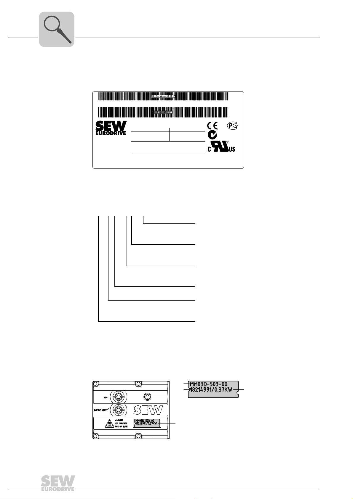
3.4.1 Nameplate
The following figure gives an example of a nameplate of a MOVIMOT
3.4.2 Type designation
The following table shows the type designation of the MOVIMOT
®
inverter:
9007201212668299
®
inverter:
MM 15 D – 503 – 00
The available variants are listed in the "MOVIMOT
3.4.3 Unit identification
The unit identification [1] on the top of the MOVIMOT
about the inverter type [2], inverter part number [3], unit power [4].
Variant
00 = Standard
Connection type
3 = 3-phase
Supply voltage
50 = AC 380 – 500 V
23 = AC 200 – 240 V
Version D
Motor power
15 = 1.5 kW
Unit series
MM = MOVIMOT
®
®
Gearmotors" catalog.
®
inverter provides information
16
457916555
Operating Instructions – MOVIMOT® MM..D with DRS/DRE/DRP AC Motor
Page 17
Unit Design
Type designation of the variant "mounted close to the motor"
3.5 Type designation of the variant "mounted close to the motor"
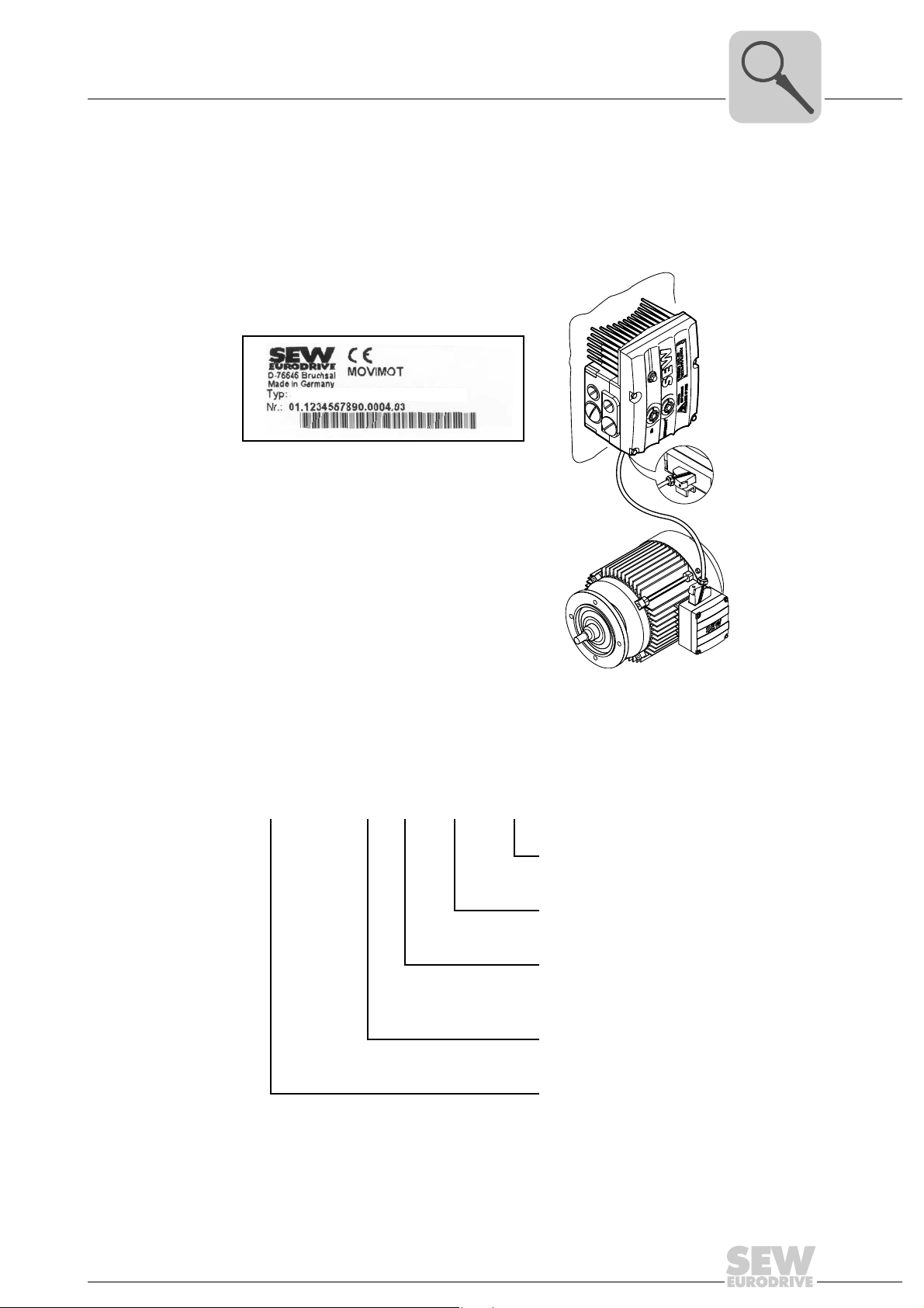
3.5.1 Nameplate
The following illustration shows an example of the MOVIMOT
to the motor with corresponding nameplate:
MM15D-503-00/0/P21A/RO1A/APG4
®
3
inverter mounted close
3.5.2 Type designation
The following table shows the type designation of a MOVIMOT
to the motor:
MM15D-503-00/0/P21A/RO1A/APG4
457921547
®
inverter mounted close
Plug connector
For the connection to the motor
Connection box design
Adapter for mounting close to the motor
21 = Size 1
22 = Size 2
Connection type
0 =
1 =
MOVIMOT® inverter
Operating Instructions – MOVIMOT® MM..D with DRS/DRE/DRP AC Motor
17
Page 18

4
Mechanical Installation
MOVIMOT® gearmotor installation
4 Mechanical Installation
4.1 MOVIMOT® gearmotor installation
4.1.1 General information
• Observe the general safety notes.
• Strictly observe all instructions as to the technical data and the permissible conditions regarding the place of installation.
• Only use the provided attachment options when mounting the MOVIMOT
• Only use mounting and locking elements that fit into the existing bores, threads and
countersinks.
4.1.2 Installation requirements
Make sure that the following requirements are met before you start installing the unit:
• The data on the nameplate of the drive matches the voltage supply system.
• The drive is undamaged (no damage caused by transportation or storage)
• The ambient temperature corresponds to the specifications in chapter "Technical
Data". Note that the temperature range of the gear unit may also be restricted (see
gear unit operating instructions).
• The MOVIMOT
ditions:
®
drive.
®
drive must not be installed under the following harmful ambient con-
Installation tolerances
– Potentially explosive atmospheres
– Oils
–Acids
– Gases
– Vapors
– Radiation
–etc.
• When the drive is installed in abrasive ambient conditions, protect the output end oil
seals against wear.
The following tables shows the permitted tolerances of the shaft ends and flanges of the
MOVIMOT
Shaft end Flanges
Diameter tolerance according to EN 50347
• ISO j6 with Ø ≤ 26 mm
• ISO k6 with Ø ≤ 38 mm up to ≤ 48 mm
• ISO m6 at Ø > 55 mm
• Center bore in accordance with DIN 332,
®
drive.
shape DR..
Centering shoulder tolerance in accordance
with EN 50347
• ISO j6 with Ø ≤ 250 mm
• ISO h6 with Ø > 300 mm
18
Operating Instructions – MOVIMOT® MM..D with DRS/DRE/DRP AC Motor
Page 19

Mechanical Installation
MOVIMOT® gearmotor installation
4
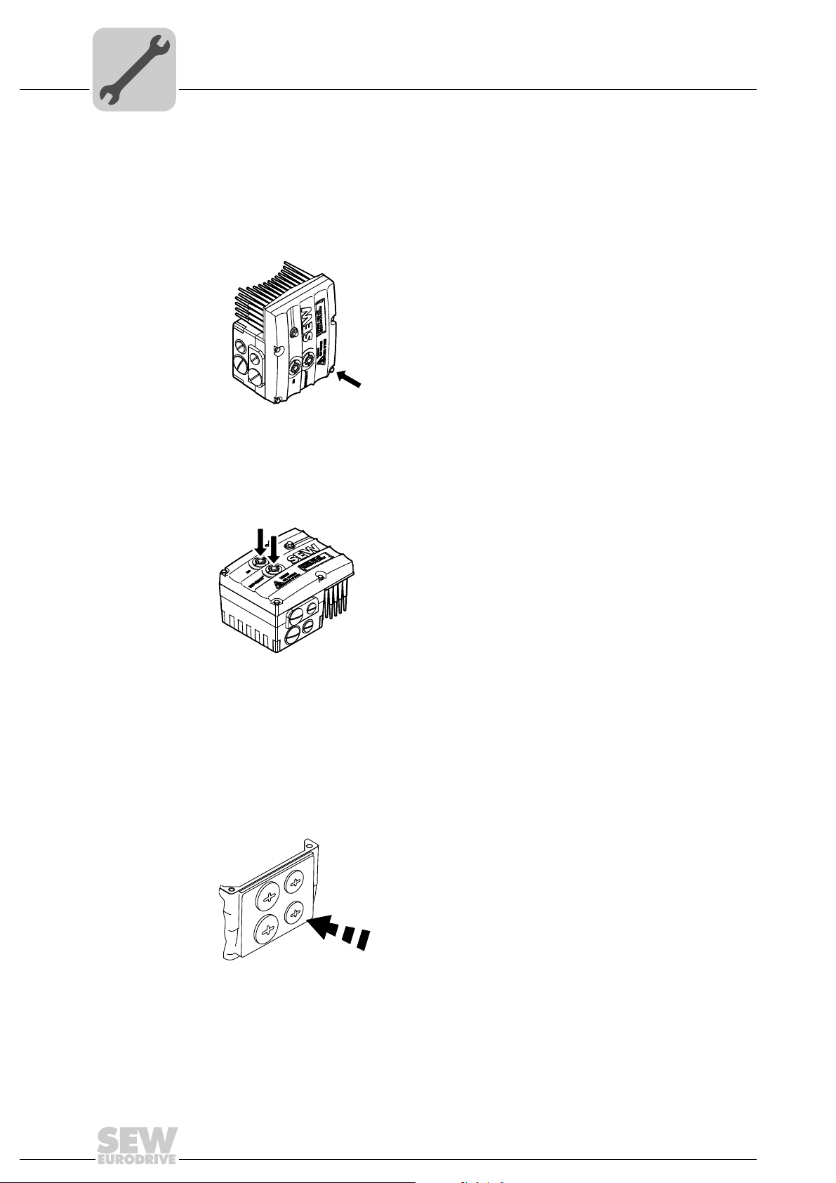
4.1.3 Installing MOVIMOT
NOTICE
Loss of warranted degree of protection if the MOVIMOT® inverter is installed incorrectly or not at all.
Damage to the MOVIMOT
• If you remove the MOVIMOT
it from moisture and dust.
Observe the following notes for mounting the MOVIMOT® drive:
• Only install the MOVIMOT
port structure.
• Observe the mounting position specified on the motor nameplate.
• Thoroughly remove any anti-corrosion agent from the shaft end. Use a commercially
available solvent. Do not allow the solvent to penetrate the bearings and shaft seals
– this could damage the material.
• Align the motor carefully to avoid placing any unacceptable strain on the motor
shafts. Observe the permitted overhung and axial loads specified in the "MOVIMOT
Gearmotors" catalog.
• Do not jolt or hammer the shaft end.
• Use an appropriate cover to prevent objects or fluids from entering motors in vertical
mounting positions.
®
®
inverter.
®
inverter from the connection box, you must protect
®
drive on a level, low-vibration, and torsionally rigid sup-
®
• Ensure sufficient clearance around the unit to allow for adequate cooling. Avoid the
drawing in of warm outlet air of other units.
• Balance components that were subsequent mounted to the shaft with a half key (output shafts are balanced with a half key).
• Existing condensation drain holes are sealed with plastic plugs.
Only open them, if necessary.
Open condensation drain holes are not permitted. If condensation drain holes are
open, higher enclosures are no longer possible.
4.1.4 Installation in damp locations or in the open
Observe the following notes for mounting the MOVIMOT
open:
• Use suitable cable glands for the cables. Use reducing adapters, if necessary.
• Coat the threads of the cable glands and filler plugs with sealing compound and
tighten them properly. Then coat the cable glands again.
• Seal the cable entries properly.
• Clean the sealing faces of the MOVIMOT
• If the corrosion protection coating is damaged, restore the coating.
• Check whether the degree of protection specified on the nameplate is permitted in
the ambient conditions on site.
®
drive in damp areas or in the
®
inverter well before re-assembly.
Operating Instructions – MOVIMOT® MM..D with DRS/DRE/DRP AC Motor
19
Page 20
4
Mechanical Installation
Installation of MOVIMOT® options
4.2 Installation of MOVIMOT® options
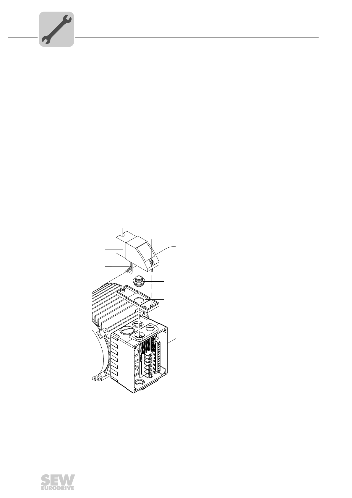
4.2.1 MLU11A / MLU21A / MLG..A option
Scope of delivery • MLU11A / MLU21A / MLG..A upper part [2]
• 2 screws [1]
• Transit bolt [4]
• MLU11A / MLU21A / MLG..A lower part [5]
Installation 1. Remove a screw plug on the MOVIMOT
2. Fix the lower part [5] on the MOVIMOT
bolt [4] (tightening torque 2.5 Nm / 22 lb.in).
3. Route the connection cable [3] through the transit bolt [4] into the inside of the
MOVIMOT
®
connection box.
4. Fit the upper part [2] onto the lower part [5] and fasten it with two screws [1] (tightening torque 0.9 – 1.1 Nm / 8 – 10 lb.in).
Mount the option in the following position only:
[1]
[1]
[2]
[3]
[4]
[5]
®
connection box.
®
connection box and fasten it with a transit
20
458285835
For more information about connecting the MLU11A/MLU21A option, refer to sec. "Connection of option MLU11A/MLU21A" (page 42).
For more information about connecting the MLG..A option, refer to sec. "Connection of
option MLG..A" (page 43).
Operating Instructions – MOVIMOT® MM..D with DRS/DRE/DRP AC Motor
Page 21
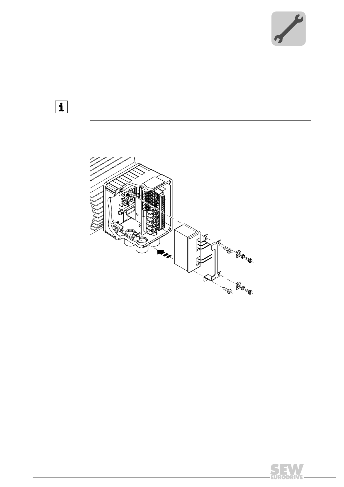
4.2.2 MLU13A option
Option MLU13A is installed in the modular connection box at the factory. If you have any
questions about retrofitting the option, please contact the SEW-EURODRIVE service.
The following figure depicts an installation example. The installation depends on the
used connection box and on other installed options, if there are any.
Mechanical Installation
Installation of MOVIMOT® options
INFORMATION
Only install this option in combination with the modular connection box of MOVIMOT
MM03D-503-00 – MM40D-503-00.
4
®
1113300875
For more information about connecting the MLU13A option, refer to chapter "Connection
of option MLU13A" (page 42).
Operating Instructions – MOVIMOT® MM..D with DRS/DRE/DRP AC Motor
21
Page 22
4
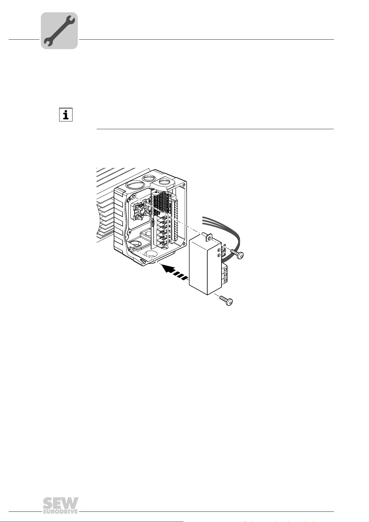
4.2.3 MNF21A option
Mechanical Installation
Installation of MOVIMOT® options
Option MNF21A is installed in the modular connection box at the factory. If you have any
questions about retrofitting the option, please contact the SEW-EURODRIVE service.
INFORMATION
Only install this option in combination with the modular connection box of MOVIMOT
MM03D-503-00 – MM15D-503-00.
The following figure depicts an installation example. The installation depends on the
used connection box and on other installed options, if there are any.
®
2753184651
For more information about connecting the MNF21A option, refer to chapter "Connecting the MNF21A option" (page 44).
22
Operating Instructions – MOVIMOT® MM..D with DRS/DRE/DRP AC Motor
Page 23
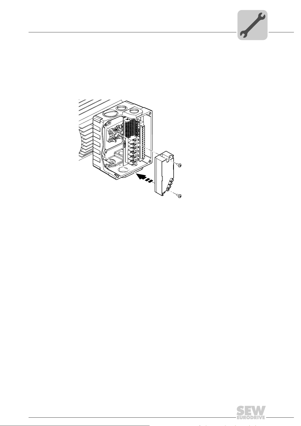
4.2.4 URM/BEM/BES options
The URM, BEM and BES options are installed in the connection box at the factory. If you
have any questions about retrofitting the options URM, BEM, or BES, please contact the
SEW-EURODRIVE service.
The following figure depicts an installation example. The installation depends on the
used connection box and on other installed options, if there are any.
Mechanical Installation
Installation of MOVIMOT® options
4
458307467
For more information about connecting the URM option, refer to chapter "Connection of
option URM" (page 45).
For more information about connecting the BEM option, refer to chapter "Connection of
option BEM" (page 46).
For more information about connecting the BES option, refer to chapter "Connection of
option BES" (page 47).
Operating Instructions – MOVIMOT® MM..D with DRS/DRE/DRP AC Motor
23
Page 24
4
AB
2
M4
8
m
m
68 mm
56 mm
Ø 4,3 mm
M4
[1] M4 x 5 + a
M4 x 25
60
m
m
88
m
m
A
A
A
A
B
B
[3]
[2]
[4]
[5]
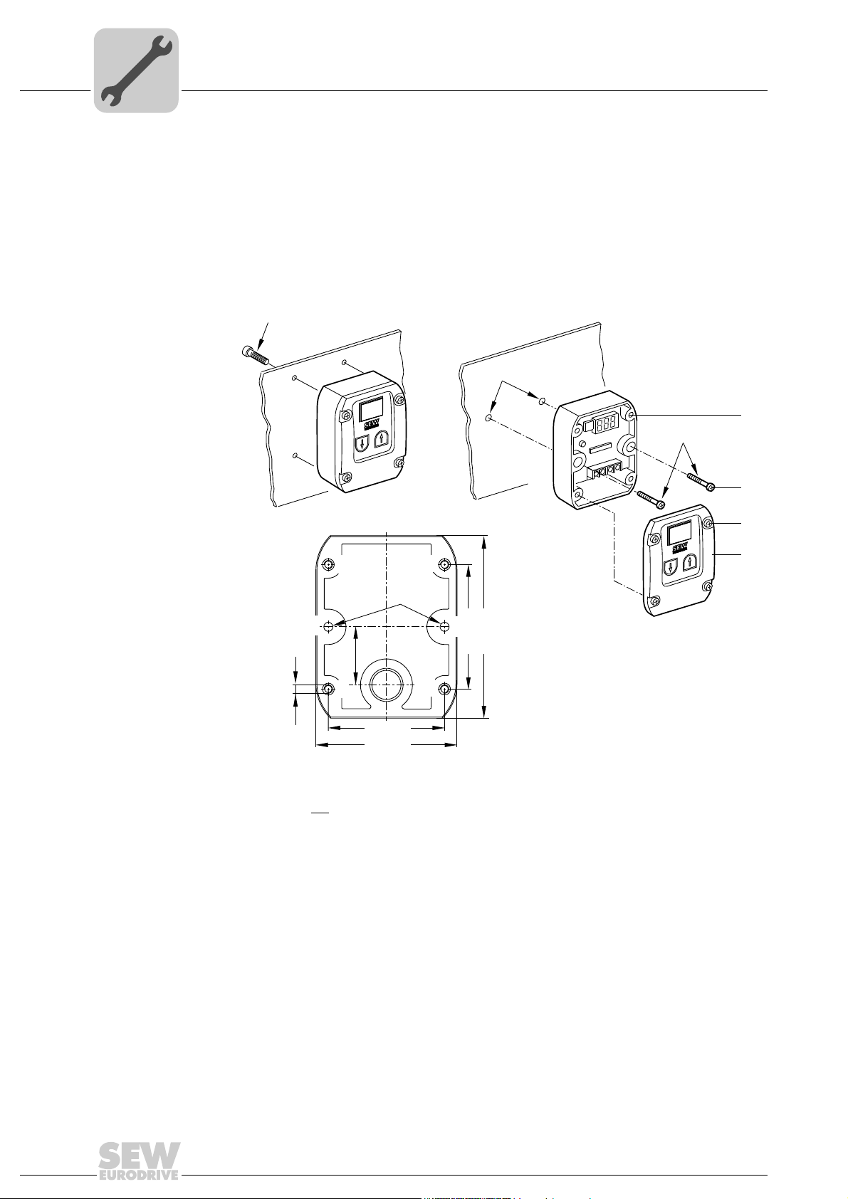
4.2.5 Installation MBG11A
Mechanical Installation
Installation of MOVIMOT® options
There are two ways to mount option MBG11A to a wall:
A: Mounting from the rear using 4 tapped holes.
(Tightening torque of retaining screw [1]: 1.6 – 2.0 Nm / 14 – 18 lb.in)
B: Mounting from the front using 2 retaining holes
(Tightening torque of retaining screw [3]: 1.6 – 2.0 Nm / 14 – 18 lb.in)
24
a = Wall thickness
Screws are not
Fit the upper part [5] onto the lower part [2] and fasten it with two screws [4] (tightening
torque 0.3 Nm / 2.6 lb.in).
For more information about connecting the MBG11A option, refer to sec. "Connection of
option MBG11A" (page 48).
included in the scope of delivery.
Operating Instructions – MOVIMOT® MM..D with DRS/DRE/DRP AC Motor
322404747
Page 25
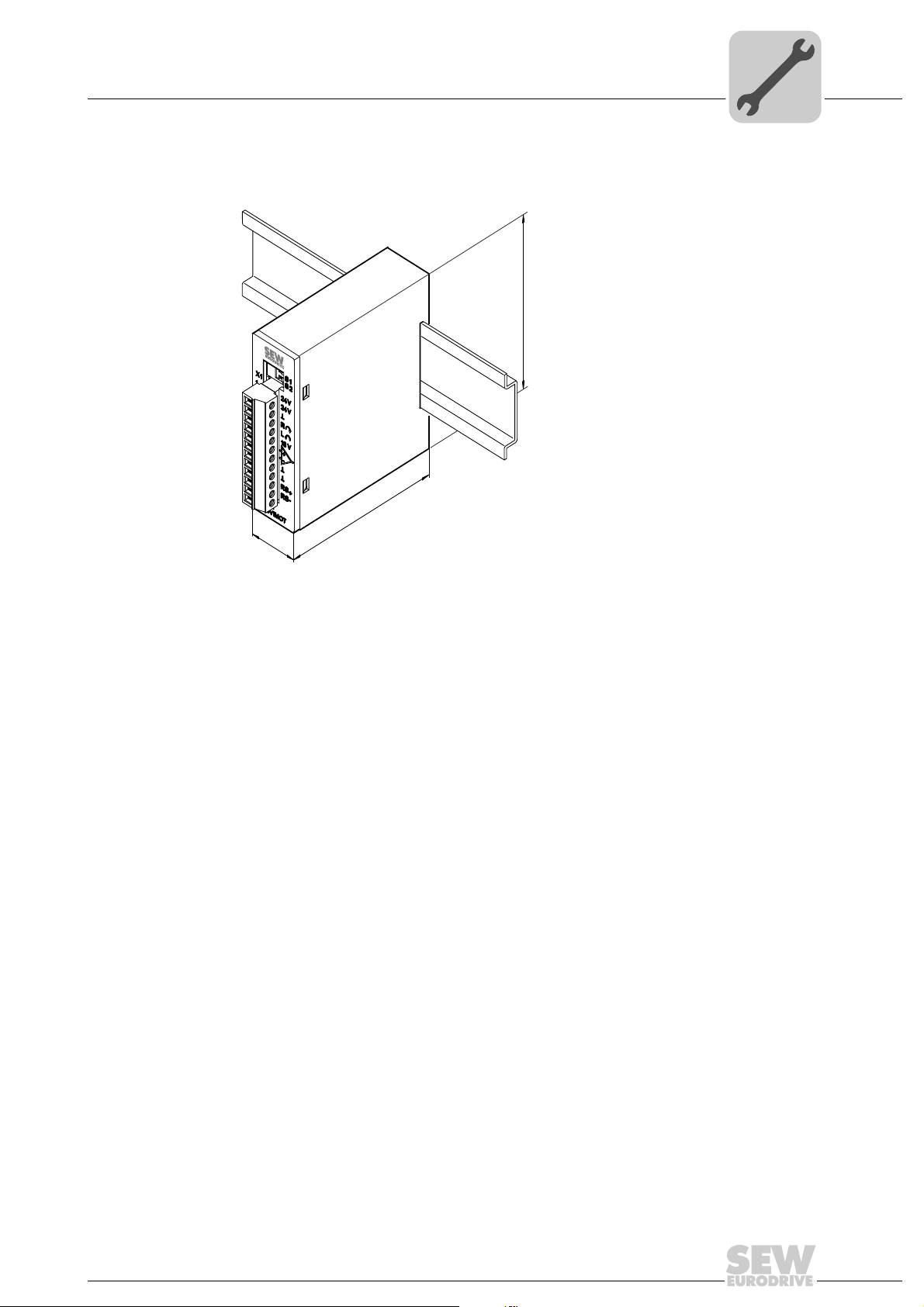
4.2.6 MWA21A option
22,5
74
75
Install option MWA21A in the control cabinet on a mounting rail according to EN 50022:
Mechanical Installation
Installation of MOVIMOT® options
4
322411915
For more information about connecting the MWA21A option, refer to sec. "Connection
of option MWA21A" (page 49).
Operating Instructions – MOVIMOT® MM..D with DRS/DRE/DRP AC Motor
25
Page 26
4
rpm%
n11 n12
n13
f/A
RS485
COM
f
c max
IU
MWF11A
MWF11A
n11
n12
n13
X1
X3
X2
X4
X5
X4
rpm%
n13
f/A
RS485
COM
f
c ma
x
I
X4
100
75
52
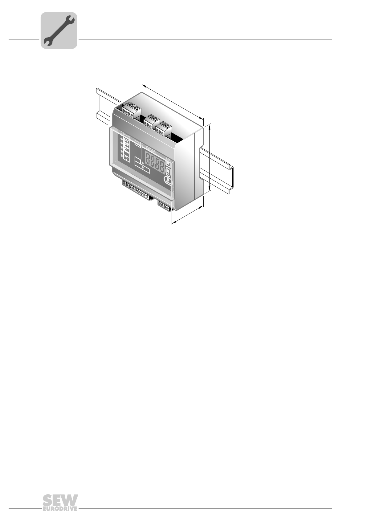
4.2.7 MWF11A option
Mechanical Installation
Installation of MOVIMOT® options
Install option MWF11A in the control cabinet on a mounting rail according to EN 50022:
3180221579
For more information about connecting the MWF11A option, refer to chapter "Connection of option MWF11A" (page 50).
26
Operating Instructions – MOVIMOT® MM..D with DRS/DRE/DRP AC Motor
Page 27
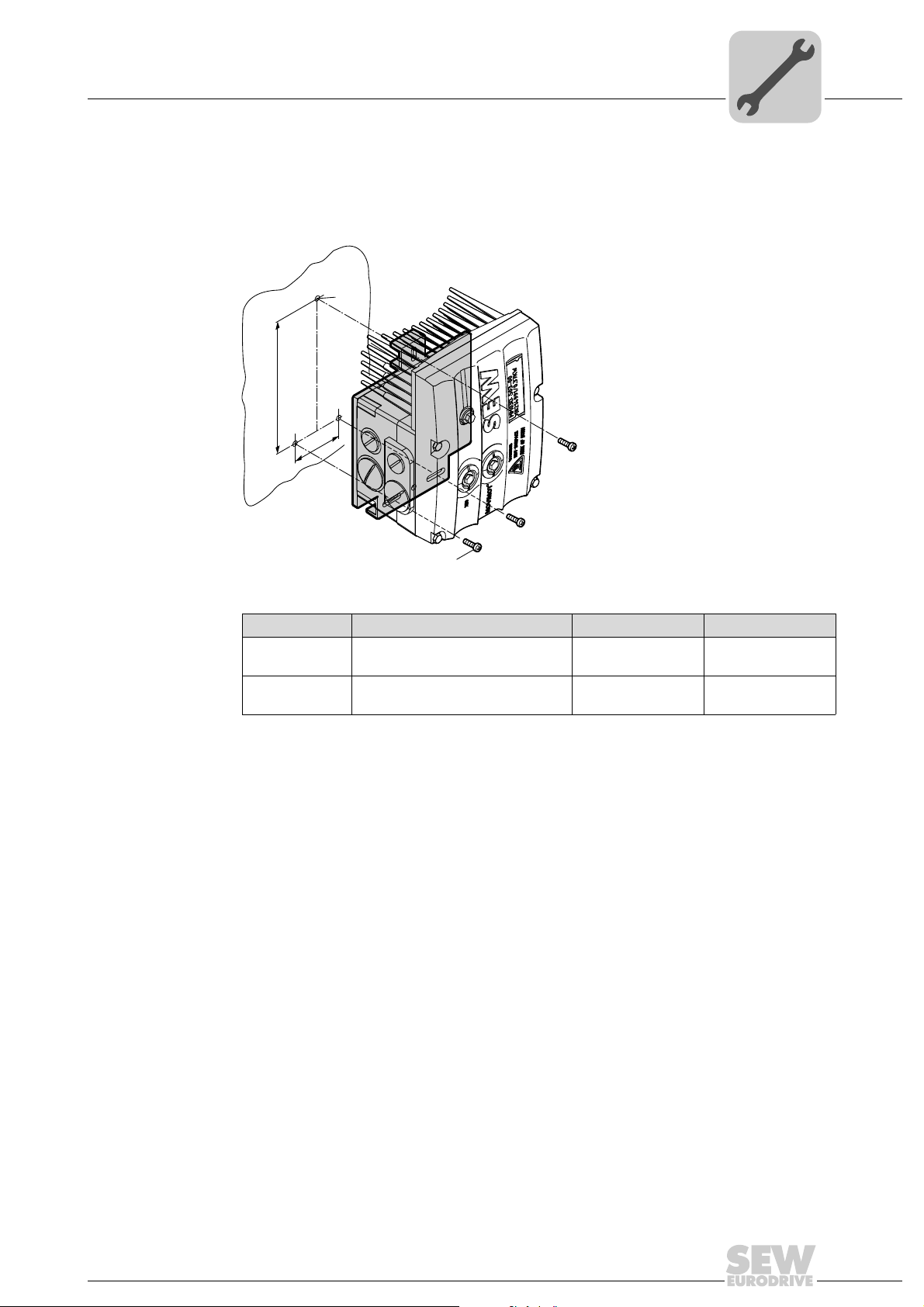
Mechanical Installation
Installation of the MOVIMOT® inverter close to the motor
4.3 Installation of the MOVIMOT® inverter close to the motor
The following figure shows the mounting dimensions for installing the MOVIMOT® inverter close to the motor:
M6
A
B
4
M6
Size Type A B
1
2 / 2L
MM03D503-00 – MM15D-503-00
MM03D233-00 – MM07D-233-00
MM22D503-00 – MM40D-503-00
MM11D233-00 – MM22D-233-00
140 mm 65 mm
170 mm 65 mm
458277771
Operating Instructions – MOVIMOT® MM..D with DRS/DRE/DRP AC Motor
27
Page 28
4
Mechanical Installation
Tightening torques
4.4 Tightening torques
4.4.1 MOVIMOT® inverter
Tighten the screws on the MOVIMOT
nally across.
®
inverter using 3.0 Nm (27 lb.in) working diago-
458577931
4.4.2 Screw plugs
Tighten screw plugs of potentiometer f1 and connection X50 using 2.5 Nm (22 lb.in).
4.4.3 Cable glands
It is essential to observe the manufacturer's specifications for the cable glands.
4.4.4 Blanking plug cable entries
Tighten blanking plug screws with 2.5 Nm (22 lb.in).
458570379
28
322777611
Operating Instructions – MOVIMOT® MM..D with DRS/DRE/DRP AC Motor
Page 29
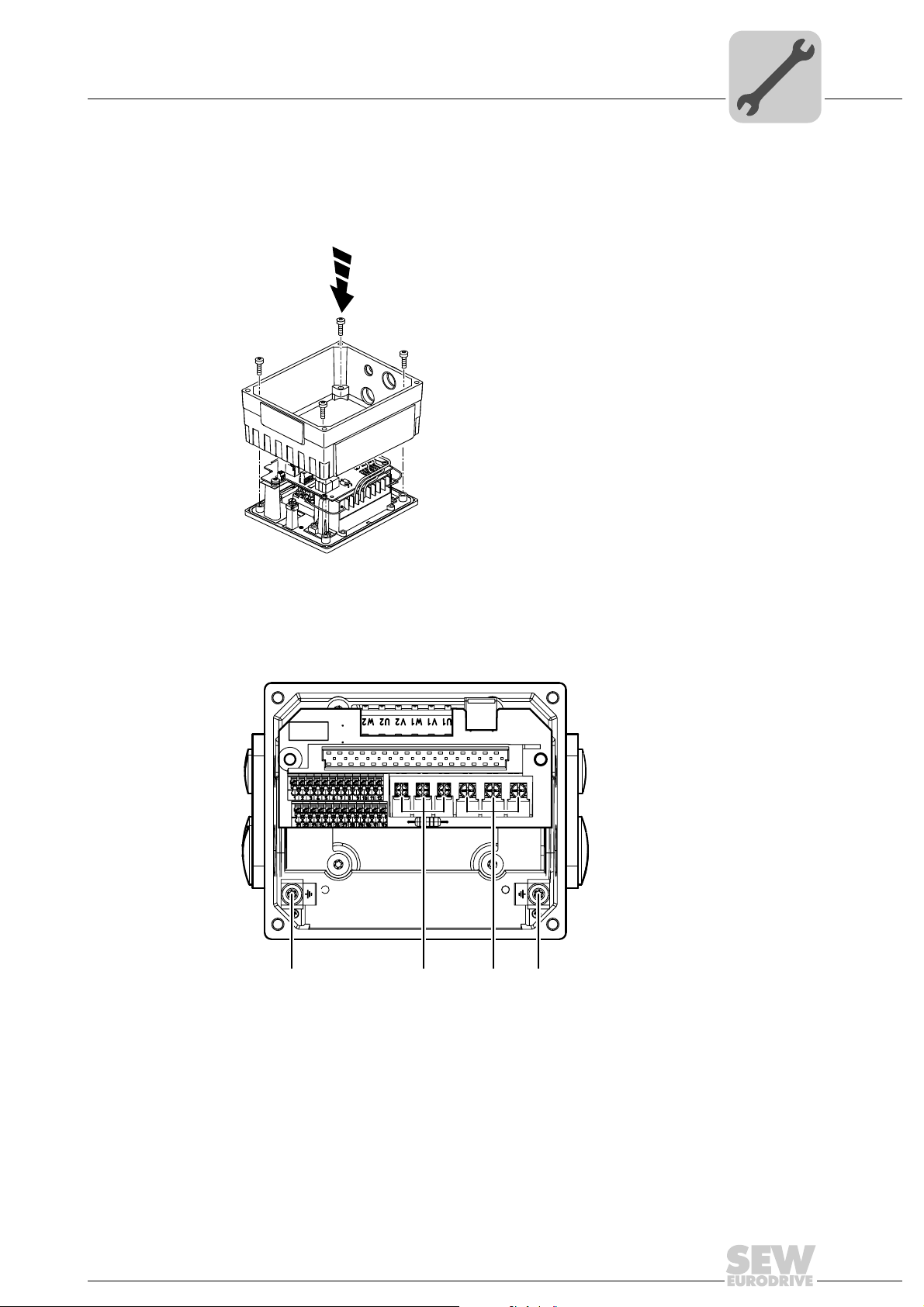
4.4.5 Modular connection box
[3][3] [1] [2]
For fastening the connection box on the mounting plate, tighten screws using 3.3 Nm
(29 lb.in).
Mechanical Installation
Tightening torques
4
4.4.6 Tightening torques for terminals
Use the following tightening torques for terminals during installation:
322786187
458605067
[1] 0.8 – 1.5 Nm (7 – 13 lb.in)
[2] 1.2 – 1.6 Nm (11 – 14 lb.in)
[3] 2.0 – 2.4 Nm (18 – 21 lb.in)
Operating Instructions – MOVIMOT® MM..D with DRS/DRE/DRP AC Motor
29
Page 30
5
Electrical Installation
Installation instructions
5 Electrical Installation
5.1 Installation instructions
5.1.1 Supply system connection
• The rated voltage and frequency of the MOVIMOT
data for the power supply system.
• Install line fuses at the beginning of the power supply cable behind the supply bus
junction, see F11/F12/F13 in chapter "Connection of MOVIMOT
Use only D, D0 or NH fuses, or circuit breakers for F11/F12/F13. Select the fuse size
according to the cable cross section.
• SEW-EURODRIVE recommends using earth-leakage monitors with pulse code
measuring in voltage supply systems with a non-grounded star point (IT systems).
The use of such devices prevents the earth-leakage monitor mis-tripping due to the
earth capacitance of the inverter.
• Cable cross section: according to input current I
"Technical Data").
®
inverter must correspond to the
®
drive".
for rated power (see chapter
mains
®
5.1.2 Permitted cable cross section of MOVIMOT
terminals
Power terminals Observe the permitted cable cross sections for installation:
Power terminals
2
Cable cross section 1.0 mm
AWG17 – AWG12 (2 x AWG12)
Conductor end sleeves • For single assignment:
Only connect single-wire conductors or flexible conductors with conductor end sleeve (DIN 46228, material ECU) with or without insulating shrouds
• For double assignment:
Only connect flexible conductors with conductor end
sleeve (DIN 46228-1, material E-CU) without insulating shrouds
• Permitted length of the conductor end sleeve: At least 8
mm
- 4.0 mm2 (2 x 4.0 mm2)
Control terminals Observe the permitted cable cross sections for installation:
Control terminals
Cable cross section
• Single-wire conductor
(bare wire)
• Flexible conductor
(bare litz wire)
• Conductor with end sleeve
Without
• Conductor with end sleeve
With
Conductor end sleeves • Only connect single-wire conductors or flexible conduc-
insulating shrouds
insulating shrouds
tors with or without
material E-CU)
• Permitted length of the conductor end sleeve: At least 8
mm
0.5 mm
AWG20 – AWG17
0.5 mm2 – 0.75 mm
AWG20 – AWG19
conductor end sleeve (DIN 46228,
2
– 1.0 mm
2
2
30
Operating Instructions – MOVIMOT® MM..D with DRS/DRE/DRP AC Motor
Page 31

5.1.3 Using the control terminals X5 – X6
1.
2.
Note the following information for actuating the control terminal clamps:
Electrical Installation
Installation instructions
5
Connecting the conductor
Without pushing the actuation button
9007199919965835 9007200623153931
The following conductors can be installed
directly (without tool) up to two cross-section sizes below the nominal cross section:
• Single-wire conductors
• Flexible conductors with end sleeves
Connecting the conductor
After pressing the activation button
1.
2.
When connecting the following conductors, you must press the actuation button
on top to open the clamping spring:
• Untreated, flexible conductors
• Conductors with small cross sections
that cannot be plugged in directly
Removing the conductor
After pressing the activation button
9007199735787147
Before removing the conductor, first press the actuation button on top.
Operating Instructions – MOVIMOT® MM..D with DRS/DRE/DRP AC Motor
31
Page 32

5
5.1.4 Earth-leakage circuit breaker
Electrical Installation
Installation instructions
Electric shock due to incorrect earth-leakage circuit breaker type.
Severe or fatal injuries.
MOVIMOT
leakage circuit breaker is used for protection against direct or indirect contact, only install a type B earth-leakage circuit breaker on the power supply end of the MOVIMOT
inverter.
• Do not use a conventional earth leakage circuit-breaker as a protective device. Uni-
• SEW-EURODRIVE recommends that you do not use earth-leakage circuit breakers.
WARNING
®
can cause direct current in the protective earth. In cases where an earth-
®
versal current-sensitive earth leakage circuit-breakers (tripping current 300 mA) are
permitted as a protective device. During normal operation of MOVIMOT
earth-leakage currents of > 3.5 mA can occur.
However, if an earth-leakage circuit breaker is stipulated for direct or indirect protection against contact, observe the note above in accordance with EN 61800-5-1.
®
inverter,
5.1.5 Line contactor
NOTICE
Damage to the MOVIMOT® inverter due to jogging of the K11 line contactor.
Damage to the MOVIMOT
• Do not use the K11 input contactor (see wiring diagram (page 36)) for jog mode,
but only for switching the inverter on and off. For jog mode, use the the commands
"CW / Stop" or "CCW / Stop".
• Observe a minimum switch-off time of 2 s for the line contactor K11.
• Only use a contactor of utilization category AC3 (EN 60947-4-1) as a line contactor.
®
inverter.
32
Operating Instructions – MOVIMOT® MM..D with DRS/DRE/DRP AC Motor
Page 33

5.1.6 Notes on PE connection
[1]
M5
WARNING
Electric shock due to incorrect connection of PE.
Severe or fatal injuries.
• The permitted tightening torque for the screw is 2.0 – 2.4 Nm (18 – 21 lb.in).
• Observe the following notes regarding PE connection.
Electrical Installation
Installation instructions
5
Prohibited assembly Recommendation:
Assembly with forked cable lug
Permitted for all cross sections
323042443 323034251 323038347
[1] Forked cable lug suitable for M5 PE screws
Assembly with solid connecting wire
Permitted for cross sections up to
max. 2.5 mm
2.5 mm²
2
M5
Earth-leakage currents ≥ 3.5 mA can occur during normal operation. To meet the requirements of EN 61800-5-1, observe the following notes:
• The protective earth (PE) connection must meet the requirements for plants with high
earth-leakage currents.
• This usually means
– installing a PE connection cable with a minimum cross section of 10 mm
– or installing a second PE connection cable in parallel with the original PE connec-
tion.
2
Operating Instructions – MOVIMOT® MM..D with DRS/DRE/DRP AC Motor
33
Page 34

5
5.1.7 EMC-compliant installation
Electrical Installation
Installation instructions
INFORMATION
This drive system is not designed for operation on a public low voltage supply system
that supplies residential areas.
This is a product with restricted availability in accordance with IEC 61800-3. It may
cause EMC interference. In this case, it is recommended for the operator to take suitable measures.
For detailed information on EMC compliant installation, refer to the publication "Electromagnetic Compatibility in Drive Engineering" from SEW-EURODRIVE.
With respect to the EMC regulation, frequency inverters cannot be operated as standalone units. Regarding EMC, they can only be evaluated when they are integrated in a
drive system. Conformity is declared for a described, CE-typical drive system. These operating instructions contain further information.
5.1.8 Installation above 1000 m asl
MOVIMOT
in altitudes of 1000 – 4000 m above sea level
• The nominal continuous power is reduced due to the reduced cooling above 1000 m
®
drives with line voltages of 200 – 240 V or 380 – 500 V, can be also used
(see chapter "Technical Data").
1)
. Observe the following conditions:
• Above 2000 m asl, the air and creeping distances are only sufficient for overvoltage
class 2. If the installation calls for overvoltage class 3, you will have to install additional external overvoltage protection to limit overvoltage peaks to 2.5 kV phase-tophase and phase-to-ground.
• If safe electrical disconnection is required, it must be implemented outside the unit
for altitudes of 2000 m above sea level and higher (safe electrical disconnection in
accordance with EN 61800-5-1).
• In installation altitudes between 2000 m to 4000 msl, the permitted nominal power
supply voltages are reduced as follows:
– By 6 V per 100 m for MM..D-503-00
– By 3 V per 100 m for MM..D-233-00
5.1.9 Connecting 24 V supply
• Power the MOVIMOT
MLG..A options.
5.1.10 Binary control
• Connect the required control leads.
• Use shielded cables as control cables and route them separately from supply system
cables.
®
inverter either via an external 24 V supply or the MLU..A or
34
1) The maximum altitude is limited by creeping distances and flameproof components, such as capacitors.
Operating Instructions – MOVIMOT® MM..D with DRS/DRE/DRP AC Motor
Page 35

5.1.11 Control via RS-485 interface
The MOVIMOT
trollers:
• MOVIFIT
• Fieldbus interfaces MF.. or MQ..
• PLC bus master
• MLG..A option
• MBG11A option
• MWA21A option
• MWF11A option
®
MC
INFORMATION
• Connect only one bus master to the MOVIMOT® drive.
• Use shielded twisted-pair cables as control cables.
• Route the control cables separately from the power supply cables.
Electrical Installation
Installation instructions
®
drive is controlled via the RS-485 interface by one of the following con-
5
5.1.12 Protection devices
• MOVIMOT
External overload devices are not necessary.
5.1.13
Field wiring power
terminals
Short circuit current rating
Branch circuit protection
Motor overload
protection
Note the following points for UL-compliant installation:
• Only use copper conductors with a thermal rating of 60/75 °C.
• The permitted tightening torque of the power terminals is 1.5 Nm (13 Ib.in).
Suitable for use on a circuit capable of delivering not more than 200,000 rms
symmetrical amperes.
The max. voltage is limited to 500 V.
Integral solid state short circuit protection does not provide branch circuit protection.
Branch circuit protection must be provided in accordance with the National Electrical
Code and any applicable local codes.
The max. fuse rating is 25 A / 600 V.
MOVIMOT
justed to 140% of the rated motor current.
®
drives are equipped with integrated protection devices against overload.
®
MM..D is equipped with motor overload protection with a trip current ad-
®
Ambient temperature
Operating Instructions – MOVIMOT® MM..D with DRS/DRE/DRP AC Motor
MOVIMOT
rated output current. To determine the output current rating at higher than 40 °C, the output current should be derated 3.0 % per °C between 40 °C and 60 °C.
MM..D is suitable for an ambient temperature of 40 °C, max. 60 °C with de-
35
Page 36

5
M
3~
L1
L2
L3
PE
K11
F11/F12/F13
K1
RS-485
X1: 13
X1: 14
X1: 15
X1: L1
X1: L2
X1: L3
24V X6: 1,2,3
X6: 4,5,6
R X6: 11,12
L X6: 9,10
X6: 7,8
f1/f2
X5: 21,22
X5: 23,24
HT1
HT2
=
+
-
RD
WH
BE/BR
MOVIMOT
®
[1] [2]
[3]
[4]
[5]
[6]
DC 24 V
BU
X10:1
X10:2
X10:3
[7]
[8]
X5: 25,26
X5: 27,28
X5: 29,30
X5: 31,32
K1a
K1b
RS-
RS+
R
X6: 11,12
L
X6: 9,10
24V X6: 1,2,3
R
X6: 11,12
L
X6: 9,10
24V X6: 1,2,3
f1/f2 X6: 7,8
R
X6: 11,12
L
X6: 9,10
24V X6: 1,2,3
R
X6: 11,12
L
X6: 9,10
24V X6: 1,2,3
R
X6: 11,12
L
X6: 9,10
24V X6: 1,2,3
R
X6: 11,12
L
X6: 9,10
24V X6: 1,2,3
Electrical Installation
Connection of the MOVIMOT® drive
5.2 Connection of the MOVIMOT® drive
Functions of the CW/stop and CCW/stop terminals in
binary control mode:
X6: 9,10
X6: 11,12
24V X6: 1,2,3
R
L
18014399135542795
Direction of rotation
CW active
Direction of rotation
CCW active
Functions of terminals f1/f2:
X6: 9,10
X6: 11,12
24V X6: 1,2,3
R
L
f1/f2 X6: 7,8
Setpoint f1 active Setpoint f2 active
Functions of the CW/stop and CCW/stop terminals
with control via RS-485 interface/fieldbus:
Both directions of rotation
are enabled
Only CW direction
is enabled
Pre-selected setpoints for CCW rota-
tion result in standstill of drive
36
[1] DC 24 V supply
(external or via option MLU..A / MLG..A)
[2] CW/stop
[3] CCW/stop
[4] Setpoint changeover f1/f2
[5] HT1 / HT2: Intermediate terminal for specific wiring dia-
grams
[6] Ready signal
(contact closed = ready for operation)
[7] BW.. braking resistor
(only for MOVIMOT
®
drives without mechanical brake)
[8] Plug connector for connecting the options BEM + BES
Operating Instructions – MOVIMOT® MM..D with DRS/DRE/DRP AC Motor
Only CCW operation
is enabled
Setpoint specifications for CW opera-
tion
cause standstill of the
drive
Drive is inhibited or is being brought
to a standstill
Page 37

5.3 MOVIMOT® plug connectors
12345
6789
12
4
3
MOVIMOT
®
L1 L2 L3
24V RS+ RS-
ASA3
AVT1
10
MOVIMOT
®
AMA6
1
2
3
4
5
6
1
2
A
C
3
4
5
6
24 V
RS+
RS-
L2
L1
L3
5.3.1 AVT1, ASA3 plug connectors
The following figure shows the assignment of optional AVT1 and ASA3 plug connectors.
Available versions:
• MM../ASA3
• MM../AVT1
• MM../ASA3/AVT1
Electrical Installation
MOVIMOT® plug connectors
5
5.3.2 AMA6 plug connectors
Operating Instructions – MOVIMOT® MM..D with DRS/DRE/DRP AC Motor
323830155
The following illustration shows the assignment of the optional AMA6 plug connector.
Possible design:
• MM../AMA6
INFORMATION
For designs with plug connectors, both directions of rotation are enabled as standard.
If only one direction of rotation is required, please observe chapter "Connection of the
MOVIMOT
RS-485 interface".
®
drive, functions of the terminals CW/stop, CCW/stop for connection via
323879563
37
Page 38

5
4
Electrical Installation
Connection between MOVIMOT® and motor when mounted close to the
5.4 Connection between MOVIMOT® and motor when mounted close to the motor
If the MOVIMOT® inverter is mounted close to the motor, the connection to the motor is
realized with a pre-fabricated hybrid cable.
Use only hybrid cables from SEW-EURODRIVE to connect the MOVIMOT
the motor.
The following designs are possible on the MOVIMOT
• A: MM../P2.A/RO.A/APG4
• B: MM../P2.A/RE.A/ALA4
The APG4 type results in the following connection options to the motor, depending on
the hybrid cable used:
®
side:
®
inverter with
Design A1 A2 A3 A4
MOVIMOT
Motor Cable gland/
Hybrid cable 0 186 742 3 0 593 076 6 0 186 741 5 0 816 325 1 for DR.63
A1
®
APG4 APG4 APG4 APG4
ASB4 APG4 ISU4
terminals
A2
APG4
[1]
0 816 326 X
0 593 278 5
0 593 755 8
for DR.71–DR.132
for DR.63
for DR.71–DR.132
APG
ASB4
38
A3
[1] Connection via terminals
Operating Instructions – MOVIMOT® MM..D with DRS/DRE/DRP AC Motor
APG4
APG4
A4
APG4
ISU4
458666635
Page 39

Electrical Installation
B1
B2
ASB4
[1]
ALA4
ALA4
Connection between MOVIMOT® and motor when mounted close to the
The APG4 design results in the following connection options to the motor, dependent
upon the hybrid cable used:
5
Design B1 B2
MOVIMOT
Motor Cable gland/terminals ASB4
Hybrid cable 0 817 948 4 0 816 208 5
®
ALA4 ALA4
458688139
[1] Connection via terminals
Operating Instructions – MOVIMOT® MM..D with DRS/DRE/DRP AC Motor
39
Page 40

5
APG4
Auftragsnummer:
R 01/00
Laenge (m):
593 278 5
Auftragsnummer:
R 01/00
Laenge (m):
593 278 5
ALA4
Electrical Installation
Connection between MOVIMOT® and motor when mounted close to the
5.4.1 Overview of connections between MOVIMOT® and motor when mounted close to the motor
MOVIMOT® inverter Design Hybrid cable Drive
MM../P2.A/RO.A/APG4 A1 Part number DR71 – DR100: 0 186 742 3
Part number DR112 – DR132: 1 811 662 0
A2 Part number: 0 593 076 6 AC motors with ASB4 plug
A3 Part number: 0 186 741 5 AC motors with APG4 plug
AC motors with cable gland
connector
connector
A4 Part number: 0 593 278 5 ()
Part number: 0 816 325 1 (
)
AC motors with plug connector ISU4
Size DR.63
R 01/00
Auftragsnummer:
593 278 5
Laenge (m):
A4 Part number: 0 593 755 8 (
Part number: 0 816 326 X (
)
)
AC motors with plug connector ISU4
Size DR.71-DR.132
R 01/00
Auftragsnummer:
593 278 5
Laenge (m):
MM../P2.A/RE.A/ALA4 B1 Part number: 0 817 948 4 AC motors with cable gland
B2 Part number: 0 816 208 5 AC motors with ASB4 plug
connector
40
Operating Instructions – MOVIMOT® MM..D with DRS/DRE/DRP AC Motor
Page 41

Electrical Installation
Connection between MOVIMOT® and motor when mounted close to the
5.4.2 Hybrid cable connection
The following tables shows the conductor assignment in hybrid cables with part no.
0 186 742 3 and 0 817 948 4 and the corresponding motor terminals of the DR motor:
DR motor terminal Wire color/hybrid cable designation
U1 Black/U1
V1 Black/V1
W1 Black/W1
4a Red/13
3a White/14
5a Blue/15
1b Black/1
2b Black/2
PE connection Green/yellow + shield end (internal shield)
The following figure shows the connection of the hybrid cable to the terminal box of the
DR motor.
5
PE
U1 V1 W1
1
aa a aa2345
1b
2b
W2 U2 V2
U1 V1 W1
BK/W1
BK/V1
BK/U1
BU
RD
WH
BK/1
BK/2
W2 U2 V2
U1 V1 W1
Operating Instructions – MOVIMOT® MM..D with DRS/DRE/DRP AC Motor
9007200445548683
41
Page 42

5
L1
L2
24V
MOVIMOT
®
YE (MLU11A), BN (MLU21A)
YE (MLU11A), BN (MLU21A)
RD
BU
L1
L2
24V
MLU..A
®
X1: 13
X1: 14
X1: 15
24V X6: 1,2,3
X6: 4,5,6
R X6: 11,12
L X6: 9,10
X6: 7,8
X5: 25,26
X5: 27,28
X5: 29,30
X5: 31,32
f1/f2
K1a
K1b
RS-
RS+
X1: L1
X1: L2
X1: L3
Electrical Installation
Connection of the MOVIMOT® options
5.5 Connection of the MOVIMOT® options
5.5.1 Connecting the MLU11A/MLU21A option
For more information about connecting the MLU11A and MLU21A options, refer to sec.
"Connection of option MLU11A/MLU21A/MLG..A" (page 20).
The following figure shows how to connect the MLU11A and MLU21A options:
5.5.2 Connection of MLU13A option
For more information about mounting the MLU13A option, refer to chapter "MLU13A option" (page 20).
The following figure shows how to connect the MLU13A option:
X1: 13
X1: L1
X1: L2
X1: 14
X1: L3
X1: 15
YE
YE
YE
X6: 4,5,6
24V X6: 1,2,3
MOVIMOT
BU
RD
X6: 7,8
L X6: 9,10
f1/f2
R X6: 11,12
X5: 25,26
X5: 27,28
X5: 29,30
RS-
K1a
K1b
®
®
X5: 31,32
RS+
L1
L2
MLU13A
24V
640436235
L3
42
Operating Instructions – MOVIMOT® MM..D with DRS/DRE/DRP AC Motor
323967371
Page 43

5.5.3 Connection of option MLG..A
For more information about mounting the MLG..A option, refer to sec. "MLU11A/
MLU21A/MLG..A option" (page 20).
The following figure shows how to connect the MLG..A option:
Electrical Installation
Connection of the MOVIMOT® options
YE (MLG11A), BN (MLG21A)
YE (MLG11A), BN (MLG21A)
5
X1: L1
X1: L2
X1: L3
MOVIMOT
®
L1
L2
MLG..A
24V
RS+
X6: 7,8
X5: 25,26
X5: 27,28
X5: 29,30
K1b
X5: 31,32
RS-
RS+
RD
BUOGGN
X1: 13
X1: 14
X1: 15
X6: 4,5,6
24V X6: 1,2,3
[1]
L X6: 9,10
f1/f2
R X6: 11,12
K1a
[1] Note the enabled direction of rotation.
See chapter "Connection of the MOVIMOT
®
drive" (page 36),
Functions of the CW/Stop and CCW/Stop terminals using control via RS-485 interface
RS-
641925899
Operating Instructions – MOVIMOT® MM..D with DRS/DRE/DRP AC Motor
43
Page 44

5
Electrical Installation
Connection of the MOVIMOT® options
5.5.4 Connection of MNF21A option
INFORMATION
Only install this option in combination with the modular connection box of MOVIMOT
MM03D-503-00 – MM15D-503-00.
For more information about mounting the MNF21A option, refer to chapter "MNF21A option" (page 22).
The following figure shows how to connect the MNF21A option:
L1
L2
L3
PE
®
F11/F12/F13
K11
[1]
MNF21A
L1
L2
L3
L1
L2
L3
BE/BR
RD WH BU
X1: 14
X1: 13
BW
[3]
X1: L3
[2]
X1: 15
[2]
AS- X6: 7
AS+ X6: 8
X6: 6
DI2
MOVIMOT
X6: 3,4
X6: 5
DI3
V024
X6: 1,2
V0
1754451723
X1: L1
X1: L2
[1] Keep the cable length for the power supply as short as possible!
[2] Keep the length of the brake cables as short as possible!
Do not route the brake cables in parallel, but as far away from the power supply cables as
possible!
[3] BW braking resistor (only in MOVIMOT
®
without mechanical brake)
®
X5: 1a,1b
24V X5: 2a,2b
44
Operating Instructions – MOVIMOT® MM..D with DRS/DRE/DRP AC Motor
Page 45

5.5.5 Connection of URM option
For more information about mounting the URM option, refer to chapter "URM/BEM option" (page 23).
The following figure shows how to connect the URM option:
Electrical Installation
Connection of the MOVIMOT® options
5
URM
13
14
15
M
3~
RD
WH
X1: L1
X1: 13
X1: L2
X1: 14
X1: L3
BE/BR
X1: 15
BU
X6: 4,5,6
24V X6: 1,2,3
MOVIMOT
X6: 7,8
L X6: 9,10
f1/f2
R X6: 11,12
X5: 25,26
X5: 27,28
X5: 29,30
RS-
K1a
K1b
324118411
®
X5: 31,32
RS+
Operating Instructions – MOVIMOT® MM..D with DRS/DRE/DRP AC Motor
45
Page 46

5
M
3~
L1
L2
L3
PE
K11
F11/F12/F13
K1
RS-485
RD
RD
BK
BK
WH
BU
BU
=
+
-
+
~~
BE/BR
BW..
BEM
MOVIMOT
13
14
15
_
U
IN
U
E
X1: 13
X1: 14
X1: 15
24V X6: 1,2,3
X6: 4,5,6
R X6: 11,12
L X6: 9,10
X6: 7,8
X5: 25,26
X5: 27,28
X5: 29,30
X5: 31,32
f1/f2
K1a
K1b
RS-
RS+
X1: L1
X1: L2
X1: L3
X10:1
X10:2
X10:3
Electrical Installation
Connection of the MOVIMOT® options
5.5.6 Connection of BEM option
For more information about mounting the BEM option, refer to chapter "URM/BEM/BES
option" (page 23).
The following figure shows how to connect the BEM option:
324134539
46
Operating Instructions – MOVIMOT® MM..D with DRS/DRE/DRP AC Motor
Page 47

5.5.7 Connection of BES option
M
3~
L1
L2
L3
PE
K11
F11/F12/F13
K1
RS-485
RD
RD
24 V
RD
BK
WH
BU
BU
-
+
BE...
DR..
BES
MOVIMOT
13
14
15
X1: 13
X1: 14
X1: 15
24V X6: 1,2,3
X6: 4,5,6
R X6: 11,12
L X6: 9,10
X6: 7,8
X5: 25,26
X5: 27,28
X5: 29,30
X5: 31,32
f1/f2
K1a
K1b
RS-
RS+
X1: L1
X1: L2
X1: L3
X10:1
X10:2
X10:3
[1]
[2]
[3]
24V
U
E
U
IN
+
=
-
NOTICE
If the connection voltage is too high, the BES option or the brake coil connected to it
can be damaged.
Damage to the BES option or the brake coil.
• Select a brake with a DC 24 V brake coil.
For more information about mounting the BES option, refer to chapter "URM/BEM/BES
option" (page 23).
The following figure shows how to connect the BES option:
Electrical Installation
Connection of the MOVIMOT® options
5
[1] BES brake control mounted in the connection box
1711602315
[2] External BW braking resistor
[3] Additional terminals for DC 24 V brake supply
Operating Instructions – MOVIMOT® MM..D with DRS/DRE/DRP AC Motor
47
Page 48

5
Electrical Installation
Connection of the MOVIMOT® options
5.5.8 Connection of MBG11A option
For more information about mounting the MBG11A option, refer to sec. "MBG11A option" (page 24).
The following figure shows how to connect the MBG11A option:
X1: L1
X1: L2
X1: L3
MOVIMOT
®
MBG11A
24V
X1: 13
X1: 14
X1: 15
X6: 4,5,6
24V X6: 1,2,3
X6: 7,8
L X6: 9,10
f1/f2
R X6: 11,12
X5: 25,26
X5: 27,28
X5: 29,30
RS-
K1a
K1b
X5: 31,32
RS+
RS+
[1]
24 V
DC
[2]
[1] Note the enabled direction of rotation.
See chapter "Connection of the MOVIMOT
®
drive" (page 36),
Functions of the CW/Stop and CCW/Stop terminals using control via RS-485 interface
[2] EMC metal cable gland
RS-
324046731
48
Operating Instructions – MOVIMOT® MM..D with DRS/DRE/DRP AC Motor
Page 49

5.5.9 Connection of MWA21A option
For more information about mounting the MWA21A option, refer to sec. "MWA21A option" (page 25).
The following figure shows how to connect the MWA21A option:
X1: L1
X1: L2
X1: L3
Electrical Installation
Connection of the MOVIMOT® options
24V
MOVIMOT
®
[3]
DC
1 24V
2 24V
3
4 R
5 L
6 10V
7 +
-
8
9
10
11 RS+
12 RS-
5
MWA21A
X6: 7,8
X5: 25,26
X5: 27,28
X5: 29,30
K1b
X5: 31,32
RS-
RS+
X1: 14
X1: 13
X1: 15
X6: 4,5,6
24V X6: 1,2,3
L X6: 9,10
f1/f2
R X6: 11,12
K1a
[1]
[2][2]
[1] Note the enabled direction of rotation.
See chapter "Connection of the MOVIMOT
®
drive" (page 36),
Functions of the CW/Stop and CCW/Stop terminals using control via RS-485 interface
[2] EMC metal cable gland
[3] Potentiometer using the 10 V reference voltage [A]
or potential-free analog signal [B]
6 10V
7 +
8
9
10
-
MWA21A
[A]
6 10V
7 +
8
9
10
-
[B]
MWA21A
324061323
324089483
Operating Instructions – MOVIMOT® MM..D with DRS/DRE/DRP AC Motor
49
Page 50

5
Electrical Installation
Connection of the MOVIMOT® options
5.5.10 Connection of MWF11A option
For more information about mounting the MWF11A option, refer to chapter "MWF11A
option" (page 26).
The following figure shows how to connect the MWF11A option:
4 3 2 1 3 2 1 3 2 1
1 2 3 4 1 2 3 4
RS-485 interface
X1 1 RS-485 + connection to MOVIMOT
X1 X2 X3
MWF11A
X4 X5
5 6 7 8 9
2 RS-485- connection to MOVIMOT
3 RS-485 GND connection to MOVIMOT
4 Shielding
3184574347
®
®
®
Frequency input
X2 1 A
2 No function
3GND
Voltage supply
X3 1 +24 V (IN)
2+24V (OUT)
3GND
Control terminals
X4 1 Enable CW
2 Enable CCW
3 Enable/rapid stop
4n11
5 n12
6 Error reset
7 /output fault
8 /output (short-circuit proof) fault
9GND
Analog input (differential)
X5 1 10 V off (for 47 kΩ potentiometer)
2AI11
3 AI12 (reference)
4GND
50
Operating Instructions – MOVIMOT® MM..D with DRS/DRE/DRP AC Motor
Page 51

Electrical Installation
MWF11A
X1 X2 X3
X4 X5
1 2 3 4 1 2 3 4
4 3 2 1 3 2 1 3 2 1
5 6 7 8 9
M
MOVIMOT
®
M
+U
B
GND
A
GND
N2
N1
RS -
GND
+U
B
RS +
47 k
Ω
3
3
3 3
1234
X5
0...10V
[13]
0...20 mA
[12]
1kΩ
+U
B2
+U
B2
0V
0V
[2]
[3]
[1]
[1]
[4]
[5]
[6]
[7]
[8]
[9]
[10]
[11]
MOVIMOT
®
®
Connection of the MOVIMOT® options
Connection of MWF11A option in broadcast mode
The following figure shows an example of how to install the MWF11A option in broadcast mode:
5
[1] Supply system
[2] MOVIMOT
[3] MOVIMOT
[4] Function generator
[5] In environments with increased interference level, you must ground the RS-485 cable shield at the mounting panel of
[6] Enable CW / stop
[7] Enable CCW / stop
[8] Enable/rapid stop
[9] Error reset
[10] /Fault
[11] Alternative setpoint specification
[12] I input
[13] U input
®
®
the control cabinet
with address 1
with address 2
3184656907
Operating Instructions – MOVIMOT® MM..D with DRS/DRE/DRP AC Motor
51
Page 52

5
MOVIMOT
®
DC 24 V
X1: 13
X1: 14
X1: 15
24V X6: 1,2,3
X6: 4,5,6
R X6: 11,12
L X6: 9,10
X6: 7,8
X5: 25,26
X5: 27,28
X5: 29,30
X5: 31,32
f1/f2
K1a
K1b
RS-
RS+
X1: L1
X1: L2
X1: L3
24 V
RD
BU
Electrical Installation
Connection of the MOVIMOT® options
5.5.11 Connection of forced cooling fan V
The AC motors of the DR.. series are available with optional forced cooling fan V.
The use of the V forced cooling fan expands the setting range of the setpoint speed. This
means that speeds from 150 rpm (5 Hz) can be realized continuously.
The following figure shows the routing of the forced cooling fan cable:
3169663499
The following figure shows an example for the connection of the V forced cooling fan:
3182111115
52
Operating Instructions – MOVIMOT® MM..D with DRS/DRE/DRP AC Motor
Page 53

5.6 Connection of RS-485 bus master
The following illustration shows how to connect an RS-485 bus master:
Electrical Installation
Connection of RS-485 bus master
5
X1: L1
X1: L2
X1: L3
MOVIMOT
®
RS-485
Busmaster
(SPS / PLC)
RS-485
X6: 7,8
X5: 25,26
X5: 27,28
X5: 29,30
K1b
X5: 31,32
RS-
RS+
X1: 13
X1: 14
X1: 15
X6: 4,5,6
24V X6: 1,2,3
L X6: 9,10
f1/f2
R X6: 11,12
K1a
[1]
24 V
DC
[3]
[2][2]
[1] Note the enabled direction of rotation.
See chapter "Connection of the MOVIMOT
®
drive" (page 36),
Functions of the CW/Stop and CCW/Stop terminals using control via RS-485 interface
[2] EMC metal cable gland
[3] Equipotential bonding MOVIMOT
®
/ RS-485 master
324289547
Operating Instructions – MOVIMOT® MM..D with DRS/DRE/DRP AC Motor
53
Page 54

5
DBG
DKG60B
MOVIMOT
®
Electrical Installation
Connecting the DBG keypad
5.7 Connecting the DBG keypad
MOVIMOT® drives are equipped with an X50 diagnostics interface (RJ10 plug connector) for startup, configuration and service.
The X50 diagnostics interface is located under the screw plug on top of the MOVIMOT
inverter.
You must remove the screw plug before plugging in the connector into the diagnostic
interface.
DANGER Danger of burns due to hot surfaces of the MOVIMOT
Severe injuries.
• Wait for the MOVIMOT
®
unit.
®
drive to cool down sufficiently before touching it.
®
54
1144135307
You can also connect the DBG keypad to the MOVIMOT
®
drive using option DKG60B
(5 m extension cable).
Extension
cable
DKG60B • Length 5 m
Description (= scope of delivery) Part num-
ber
0 817 583 7
• 4-core, shielded cable (AWG26)
Operating Instructions – MOVIMOT® MM..D with DRS/DRE/DRP AC Motor
Page 55

5.8 PC connection
MOVIMOT
PC +
MOVITOOLS
RS-232
RJ10
[1]
RJ10
USB
USB11A
UWS21B
®
®
MOVIMOT® drives are equipped with an X50 diagnostics interface (RJ10 plug connector) for startup, configuration and service.
The diagnostics interface [1] is located under the screw plug on top of the MOVIMOT
inverter.
You must remove the screw plug before plugging in the connector into the diagnostic
interface.
DANGER Danger of burns due to hot surfaces of the MOVIMOT
the heat sink).
Severe injuries.
• Wait for the MOVIMOT
The diagnostic interface can be connected to a PC using one of the following options:
• USB11A with USB interface, part number 0 824 831 1
Electrical Installation
PC connection
®
drive (especially
®
drive to cool down sufficiently before touching it.
5
®
• UWS21B with serial interface RS-232, part number 1 820 456 2
Scope of delivery:
• Interface adapter
• Cable with RJ10 plug connector
• Interface cable USB (USB11A) or RS-232 (UWS21B)
458786059
Operating Instructions – MOVIMOT® MM..D with DRS/DRE/DRP AC Motor
55
Page 56

6
00
I
6 "Easy" Startup
6.1 Overview
"Easy" Startup
Overview
You can select one of the following modes for starting up MOVIMOT® drives:
• When selecting "Easy", you start up the MOVIMOT
S2 and switches f2, t1, quick and easy.
•In "Expert" mode, an extended scope of parameters is available. You can use the
MOVITOOLS
to the application.
For more information on "Expert" startup, refer to sec. " 'Expert' Startup with Parameter Function " (page 116).
®
MotionStudio software or the DGB keypad to adjust the parameters
®
drive using DIP switches S1,
56
Operating Instructions – MOVIMOT® MM..D with DRS/DRE/DRP AC Motor
Page 57

6.2 Important notes on startup
00
I
INFORMATION
You must comply with the general safety notes in chapter "Safety Notes" during
startup.
WARNING
Risk of crushing due to missing or defective protective covers.
Severe or fatal injuries.
• Install the protective covers of the plant according to the instructions, also see the
operating instructions of the gear unit.
• Never start up the MOVIMOT
WARNING
Electric shock caused by dangerous voltages in the connection box. Dangerous voltages may still be present for up to one minute after disconnection from the power supply.
Severe or fatal injuries.
• De-energize the MOVIMOT
the MOVIMOT
• Secure the drive against unintended re-connection to the voltage supply.
• Wait for at least 1 minute before removing the MOVIMOT
®
inverter.
"Easy" Startup
Important notes on startup
®
drive if the protective covers are not installed.
®
drive using a suitable cut-off device before removing
®
inverter.
6
WARNING
Danger of burns due to hot surfaces of the MOVIMOT® drive (especially the heat sink)
or external options.
Severe injuries.
• Do not touch the MOVIMOT
down sufficiently.
®
drive and external options until they have cooled
WARNING
Unit malfunction due to incorrect unit setting.
Severe or fatal injuries.
• Observe the startup instructions.
• The installation must only be carried out by qualified personnel.
• Only use settings that are consistent with the function.
INFORMATION
To ensure fault-free operation, do not disconnect or connect power or signal cables
during operation.
INFORMATION
• Remove paint protection cap from the status LED before startup.
• Remove paint protection film from the nameplates before startup.
• Observe a minimum switch-off time of 2 seconds for the line contactor K11.
Operating Instructions – MOVIMOT® MM..D with DRS/DRE/DRP AC Motor
57
Page 58

6
00
I
"Easy" Startup
Requirements
6.3 Requirements
The following conditions apply to startup:
• The MOVIMOT
• Appropriate safety measures prevent the drives from starting up unintentionally.
• Appropriate safety measures must be taken to prevent risk of injury or damage to
machine.
6.4 Description of control elements
6.4.1 Setpoint potentiometer f1
NOTICE
Loss of warranted degree of protection if the screw plugs of the f1 setpoint potentiometer or the X50 diagnostics interface are installed incorrectly or not at all.
Damage to the MOVIMOT
• After setting the setpoint, make sure the screw plug of the setpoint potentiometer
has a seal and screw it in.
®
drive must be installed correctly both mechanically and electrically.
®
inverter.
Depending on the operating mode of the MOVIMOT
®
inverter, the potentiometer f1 has
different functions:
• Binary control: Setting setpoint f1
(f1 is selected via terminal f1/f2 X6:7,8 = "0")
• Control via RS-485: Setting maximum frequency f
f[Hz
]
100
f
1
[1] Potentiometer setting 329413003
6
5
75
50
25
2
123456789100
max
[1]
58
Operating Instructions – MOVIMOT® MM..D with DRS/DRE/DRP AC Motor
Page 59

6.4.2 Switch f2
3
4
5
6
7
8
3
4
5
6
7
8
00
I
"Easy" Startup
Description of control elements
Depending on the operating mode of the MOVIMOT
functions:
• Binary control: Setting setpoint f2
(f2 is selected via terminal f1/f2 X6:7,8 = "1")
®
inverter, switch f2 has different
6
6.4.3 Switch t1
• Control via RS-485: Setting minimum frequency f
Switch f2
Detent setting 0 12345678910
Setpoint f2 [Hz] 5 7 1015202535506070100
Minimum frequency
[Hz]
Use switch t1 to set the acceleration of the MOVIMOT
2 5 7 10 12 15 20 25 30 35 40
®
min
drive. The ramp times are based
on a setpoint step change of 1500 rpm (50 Hz).
Switch t1
Detent setting 012345 678910
Ramp time t1 [s] 0.1 0.2 0.3 0.5 0.7 1 235710
Operating Instructions – MOVIMOT® MM..D with DRS/DRE/DRP AC Motor
59
Page 60

6
00
I
"Easy" Startup
Description of control elements
6.4.4 DIP switches S1 and S2
NOTICE
Damage to the DIP switches caused by unsuitable tools.
Damage to the DIP switches.
• To set the DIP switches, use only suitable tools, such as a slotted screwdriver with
a blade width of no more than 3 mm.
• The force used for setting the DIP switches must not exceed 5 N.
DIP switch S1:
DIP switch S2:
626648587
S1 1 2 3 4 5 6 7 8
Meaning Binary coding
RS-485 unit
address
2021222
ON 1111 Off
OFF 0 0 0 0 On
S2 1 2 3 4 5 6 7 8
Meaning Brake type Brake
ON
OFF
Optional
brake
Standard
brake
Motor pro-
tection
3
released
without
enable
On V/f On 1111
Off VFC Off 0000
Motor power
Motor one
stage smaller
adjusted
Operating
mode
rating
Motor
monitoring
Speed
PWM fre-
quency
Variable (16,
8, 4 kHz)
4 kHz Off
Binary encoding
addit. functions
2021222
No-load
damping
On
3
60
Operating Instructions – MOVIMOT® MM..D with DRS/DRE/DRP AC Motor
Page 61

Description of the DIP switches S1
00
I
6.5 Description of the DIP switches S1
6.5.1 DIP switches S1/1 – S1/4 Selecting the RS-485 address of the MOVIMOT
"Easy" Startup
®
drive via binary coding
6
Set the following addresses depending on how the MOVIMOT
6.5.2 DIP switch S1/5
Decimal
address
S1/1 – X – X – X – X – X – X – X – X
S1/2 ––
S1/3 ––––
S1/4 ––––––––
X = ON
– = OFF
Control RS-485 address
Binary control 0
Via keypad (MLG..A, MBG..A) 1
Via fieldbus interface (MF..) 1
Via MOVIFIT
Via intelligent fieldbus interface (MQ..) 1 – 15
Via RS-485 master 1 – 15
Via MWF11A setpoint converter 1 – 15
0 1 2 3 4 5 6 7 8 9 10 11 12 13 14 15
X X ––X X ––X X ––X X
X X X X ––––X X X X
X X X X X X X X
®
inverter is controlled:
®
MC (MTM..)
1
Motor protection switched on / off
When MOVIMOT
deactivated.
To ensure that the motor is protected all the same, a TH (bimetallic thermostat) must be
installed. The TH opens the sensor circuit when the nominal response temperature is
reached (see field distributor manual).
6.5.3 DIP switch S1/6 Lower motor power rating
• When activated, DIP switch S1/6 can be used to assign the MOVIMOT
• When using a motor with a lower power rating, the MOVIMOT
• The aim of this switch S1/6 is to achieve short-term utilization of the motor's peak
• Stall protection for the motor is not possible in this operating mode (S1/6 = "ON").
®
is installed close to the motor, the motor protection function must be
®
inverter to
a motor with a lower power rating. The nominal unit power is not affected.
®
inverter is one power
level above the motor. This is why you can increase the overload capacity of the
drive. A higher current can be provided briefly, leading to higher torque ratings.
torque. The unit's current limit remains the same regardless of the switch setting. The
motor protection function is adjusted depending on the switch setting.
Operating Instructions – MOVIMOT® MM..D with DRS/DRE/DRP AC Motor
61
Page 62

6
00
I
"Easy" Startup
Description of the DIP switches S1
Power
rating
[kW] 50 Hz
0.25 DFR63L4/.. - MM03D-503-00.. MM03D-503-00.. MM05D-503-00..
0.37 DRS71S4/TH. MM03D-503-00.. MM05D-503-00.. MM05D-503-00.. MM07D-503-00..
0.55 DRS71M4/.. MM05D-503-00.. MM07D-503-00.. MM07D-503-00.. MM11D-503-00..
0.75
1.1
1.5
2.2
3
4
1) On request, SEW-EURODRIVE provides the motor assignment of motors with 230/400 V, 60 Hz or 266/
Motor type MOVIMOT® type (inverter)
230/400 V Motor in connection Motor in connection
DRS80S4/..
DRE80M4/..
DRP90M4/..
DRS80M4/..
DRE90M4/..
DRP90L4/..
DRS90M4/..
DRE90L4/..
DRP100M4/..
DRS90L4/..
DRE100M4/..
DRP100L4/..
DRS100M4/..
DRE100LC4/..
DRP112M4/..
DRS100LC4/..
DRE132S4/..
DRP132M4/..
460 V, 60 Hz.
1)
S1/6 = OFF S1/6 = ON S1/6 = OFF S1/6 = ON
MM07D-503-00.. MM11D-503-00.. MM11D-503-00.. MM15D-503-00..
MM11D-503-00.. MM15D-503-00.. MM15D-503-00.. MM22D-503-00..
MM15D-503-00.. MM22D-503-00.. MM22D-503-00.. MM30D-503-00..
22D-503-00.. MM30D-503-00.. MM30D-503-00.. MM40D-503-00..
MM
MM30D-503-00.. MM40D-503-00.. MM40D-503-00.. –
MM40D-503-00.. – – –
6.5.4 DIP switch S1/7 Setting the maximum PWM frequency
• When DIP switch S1/7 is set to "OFF", MOVIMOT
• When DIP switch S1/7 is set to "ON", MOVIMOT
6.5.5 DIP switch S1/8 No-load vibration damping
When setting DIP switch S1/8 = "ON", this function reduces resonance during no-load
operation.
®
operates with PWM frequency of
4 kHz.
®
operates with PWM frequency of
16 kHz (low noise). The unit switches to lower cycle frequencies depending on the
heat sink temperature and inverter load.
62
Operating Instructions – MOVIMOT® MM..D with DRS/DRE/DRP AC Motor
Page 63

6.6 Description of DIP switches S2
00
I
6.6.1 DIP switch S2/1 Brake type
• When using the standard brake, the DIP switch 2/1 must be set to "OFF".
• When using the optional brake, the DIP switch 2/1 must be set to "ON".
Motor Standard brake [type] Optional brake [type]
DR.63L4 BR03 –
DR.71S4 BE05 BE1
DR.71M4 BE1 BE05
DR.80S4 BE1 BE05
DRS80M4 BE2 BE1
DRE80M4 BE1 BE05
DRS90M4 BE2 BE1
DRE90M4 BE2 BE1
DRP90M4 BE1 BE2
DRS90L4 BE5 BE2
DRE90L4 BE2 BE1
DRP90L4 BE2 BE1
DRS100M4 BE5 BE2
DRE100M4 BE5 BE2
DRP100M4 BE2 BE5
DR.100L4 BE5 BE2
DR.100LC4 BE5 BE2
DRP112M4 BE5 BE11
DR.132S4 BE5 BE11
DRP132M4 BE5 BE11
"Easy" Startup
Description of DIP switches S2
S2/1 = "OFF" S2/1 = "ON"
6
Preferred brake voltage
MOVIMOT® type (inverter) Preferred brake
®
MOVIMOT
MOVIMOT
MOVIMOT
MM..D-503, size 1 (MM03.. – MM15..) 230 V
®
MM..D-503, size 2 (MM22.. – MM40..)
®
MM..D-233, size 1 and 2 (MM03.. – MM40..)
Operating Instructions – MOVIMOT® MM..D with DRS/DRE/DRP AC Motor
voltage
120 V
63
Page 64

6
00
I
6.6.2 DIP switch S2/2
"Easy" Startup
Description of DIP switches S2
Brake release without enable
When DIP switch S2/2 is set to "ON", it is possible to release the brake even if there is
no drive enable.
Binary control
functions
In binary control, the brake can be released by setting the signal at terminal f1/f2 X6:7,8
subject to the following preconditions:
Terminal status Enable sta-
R
X6:11,12LX6:9,10
"1"
"0"
"1"
"0"
"1"
"0"
"1" "1" "1" Unit not
"0" "0" "1" Unit not
All states possible Unit not
1) In "Expert" mode, parameter P600 (terminal configuration) must be set to = "0" (default) for this purpose
=> "setpoint changeover CCW/stop - CW/stop".
"0"
"1"
"0"
"1"
"1"
"0"
f1/f2
X6:7,8
"0" Unit enabled No unit
"1" Unit enabled No unit
"0" Unit not
tus
enabled
enabled
enabled
enabled
Error
status
error
error
No unit
error
No unit
error
No unit
error
Unit
error
Brake function
®
The MOVIMOT
the brake.
setpoint f1
The MOVIMOT
the brake.
setpoint f2
Brake applied
Brake applied
Brake is released for manual
movement
Brake applied
inverter controls
®
inverter controls
1)
64
Operating Instructions – MOVIMOT® MM..D with DRS/DRE/DRP AC Motor
Page 65

"Easy" Startup
00
I
Description of DIP switches S2
6
RS-485 control
functions
In RS-485 control, the brake is released via the control word:
Master
PO1
PI1
PO2
PI2
PO
PO3
PI3
PI
PO = Process output data PI = Process input data
PO1 = Control word PI1 = Status word 1
PO2 = Speed [%] PI2 = Output current
PO3 = Ramp PI3 = Status word 2
DO = Digital outputs DI = Digital inputs
MOVIMOT
DO
DI
®
+
-
329547915
By setting bit 8 in the control word, the brake can be released if the following conditions
are met:
Basic control block
15 14 13 12 11 10 9 8 7 6 5 4 3 2 1 0
Control word
not assigned
1)
Bit
"9"
Bit
"8"
Not
assign
ed
Virtual terminals for releasing the brake without drive enable
Virtual terminal for applying brake and inhibiting output stage "Stop" control command
1) Recommendation for all bits that are not assigned = "0"
Enable
Error status Status of bit 8 in
status
Unit enabled No unit error /
no communication timeout
Unit enabled No unit error /
no communication timeout
Unit not
enabled
Unit not
enabled
Unit not
No unit error /
no communication timeout
No unit error/no communication timeout
Unit error/communication timeout "1" or "0" Brake applied
enabled
1
"1" =
Reset
Not assigned
"1 1 0" = enable,
1)
otherwise stop
Brake function
control word
®
"0" The MOVIMOT
inverter controls the
brake.
"1" The MOVIMOT
®
inverter controls the
brake.
"0" Brake applied
"1" Brake is released for
manual movement
Operating Instructions – MOVIMOT® MM..D with DRS/DRE/DRP AC Motor
65
Page 66

6
00
I
"Easy" Startup
Description of DIP switches S2
Setpoint selection
for binary control
Behavior if unit not
ready
Setpoint selection in binary control depending on the state of terminal f1/f2 X6: 7,8:
Enable status Terminal f1/f2 X6:7,8 Active setpoint
Unit enabled Terminal f1/f2 X6:7,8 = "0" Setpoint potentiometer f1 active
Unit enabled Terminal f1/f2 X6:7,8 = "1" Setpoint potentiometer f2 active
If the unit is not ready, the brake is always applied irrespective of the status of terminal
f1/f2 X6:7,8 or bit 8 in the control word.
LED display The status LED flashes periodically at a fast rate (t
has been released for manual movement. This applies both for binary control and for
control via RS-485.
6.6.3 DIP switch S2/3 Control mode
• DIP switch S2/3 = "OFF": VFC operation for 4-pole motors
• DIP switch S2/3 = "ON": V/f operation reserved for special cases
6.6.4 DIP switch S2/4 Speed monitoring
• Speed monitoring (S2/4 = "ON") protects the drive when it is blocked.
• If the drive is operated at the current limit for longer than 1 second when speed mon-
itoring is active (S2/4 = "ON"), the MOVIMOT
The status LED of the MOVIMOT
®
inverter signalizes the error by slowly flashing red
(error code 08). This error only occurs when the current limit has been reached for
the duration of the deceleration time.
: t
= 100 ms : 300 ms) if the brake
on
off
®
inverter trips the speed monitoring.
6.6.5 DIP switches S2/5 – S2/8 Additional functions
• The binary coding of the DIP switches S2/5 - S2/8 allows for the activation of addi-
tional functions.
• Proceed as follows to activate possible additional functions:
Decimal
value
S2/5 –
S2/6 ––
S2/7 ––––
S2/8 ––––––––
X = ON
–= OFF
• For an overview of additional functions, refer to chapter "Selectable additional func-
tions" (page 67).
0 1 2 3 4 5 6 7 8 9 10 11 12 13 14 15
X – X – X – X – X – X – X – X
X X ––X X ––X X ––X X
X X X X ––––X X X X
X X X X X X X X
66
Operating Instructions – MOVIMOT® MM..D with DRS/DRE/DRP AC Motor
Page 67

Selectable additional functions MM..D-503-00
00
I
6.7 Selectable additional functions MM..D-503-00
6.7.1 Overview of the available additional functions
You can activate the following additional functions at the DIP switches S2/5 – S2/8:
"Easy" Startup
6
Decimal
value
0 Basic functionality, no additional function active X X –
1 MOVIMOT
2 MOVIMOT
3 MOVIMOT
4 MOVIMOT
5 MOVIMOT
6 MOVIMOT
7 MOVIMOT
8 MOVIMOT
9 MOVIMOT
10 MOVIMOT
11 Monitoring of supply-phase failure deactivated X X (page 82)
12 MOVIMOT
13 MOVIMOT® with extended speed monitoring function X X (page 86)
14 MOVIMOT
15 Not connected – – –
Brief description Operating mode Description
®
with increased ramp times X X (page 68)
®
with adjustable current limitation
(Fault if exceeded)
®
with adjustable current limitation
(can be changed using terminal f1/f2 X6:7,8)
®
with bus parameterization X – (page 71)
®
with motor protection via TH X – (page 73)
®
with maximum PWM frequency of 8 kHz X X (page 74)
®
with rapid start / stop X X (page 75)
®
with minimum frequency 0 Hz X X (page 77)
®
for hoist applications X X (page 78)
®
with minimum frequency 0 Hz and reduced
torque at low frequencies
®
with rapid start/stop and motor protection via
TH
®
with deactivated slip compensation X X (page 89)
Control via
RS-485
X X (page 68)
X X (page 69)
X X (page 81)
XX
Binary con-
trol
(page 82)
Operating Instructions – MOVIMOT® MM..D with DRS/DRE/DRP AC Motor
67
Page 68

6
5
876
S2
ON
3
4
5
6
7
8
5
876
S2
ON
3
4
5
6
7
8
00
I
"Easy" Startup
Selectable additional functions MM..D-503-00
6.7.2 Additional function 1 MOVIMOT
®
with increased ramp times
329690891
Functional description
• It is possible to set ramp times of up to 40 s.
• In RS-485 control mode, a ramp time of max. 40 s can be transmitted when using 3
process data units.
Changed ramp
times
Switch t1
Detent setting 0123456 7 8 9 10
Ramp time t1 [s] 0.1 0.2 0.3 0.5 0.7 1
= corresponds to standard setting
= changed ramp times
6.7.3 Additional function 2 MOVIMOT
20 25 30 35 40
®
with adjustable current limitation (error if exceeded)
329877131
Functional description
• The current limit can be set using switch f2.
• The setpoint f2 (for binary control) and the minimum frequency (for control via
RS485) are permanently set to the following values:
– Setpoint f2: 5 Hz
– Minimum frequency: 2 Hz
• The monitoring function comes into effect above 15 Hz. If the drive operates at the
current limit for longer than 500 ms, the unit generates an error (error 44). This is indicated by the status LED flashing red quickly.
Adjustable current
limits
68
Switch f2
Detent setting 012345678910
I
max
[%] of I
N
90 95 100 105 110 115 120 130 140 150 160
Operating Instructions – MOVIMOT® MM..D with DRS/DRE/DRP AC Motor
Page 69

6.7.4 Additional function 3
5
876
S2
ON
3
4
5
6
7
8
R
X6: 11,12
L
X6: 9,10
24V X6: 1,2,3
f1/f2 X6: 7,8
R
X6: 11,12
L
X6: 9,10
24V X6: 1,2,3
f1/f2 X6: 7,8
00
I
MOVIMOT
nal f1/f2 X6:7,8), the frequency is reduced when exceeded
"Easy" Startup
Selectable additional functions MM..D-503-00
®
with adjustable current limitation (can be changed using using termi-
329910539
6
Functional description
Response upon
reaching the current limit
System internal
values for setpoint
f2 / minimum frequency
Adjustable current
limits
The current limitation can be set using switch f2. Binary input terminal f1/f2 can be used
to switch between the maximum current limit and the set current limit.
• Upon reaching the current limit, the unit reduces the frequency and stops the ramp.
This prevents the current from rising.
• If the unit is operating at the current limit, the status LED indicates this status by flash-
ing green quickly.
• The following functions are no longer possible:
• In binary control mode: switching between setpoint f1 and setpoint f2 via terminal
f1/f2.
• In RS-485 control mode: setting the minimum frequency
• The minimum frequency in RS-485 control mode is set to 2 Hz.
Switch f2
Detent setting 012345678910
I
max
[%] of I
N
60 70 80 90 100 110 120 130 140 150 160
Selecting the current limits via
binary input termi-
f1/f2 = "0" Default current limit is active
nal f1 / f2
323614347
f1/f2 = "1" The current limitation set via switch f2 is active.
The selection can also be made when the unit is enabled.
323641099
Operating Instructions – MOVIMOT® MM..D with DRS/DRE/DRP AC Motor
69
Page 70

6
200
160
100
50
0
50
100
f [Hz]
I
max
/ I
n
[%]
[1]
[2]
200
160
100
50
0
50
10087
I
max
/ In [%]
f [Hz]
[1]
[2]
00
I
"Easy" Startup
Selectable additional functions MM..D-503-00
Influencing the current characteristic
curve
The current limit curve is calculated with a constant factor by selecting a lower current
limit.
Motor with star connection
331979659
[1] Current limit characteristic curve of standard function
[2] Reduced current limit for additional function 3 and terminals f1/f2 X6:7,8 = "1"
Motor with delta connection
70
332087051
[1] Current limit characteristic curve of standard function
[2] Reduced current limit for additional function 3 and terminals f1/f2 X6:7,8 = "1"
Operating Instructions – MOVIMOT® MM..D with DRS/DRE/DRP AC Motor
Page 71

6.7.5 Additional function 4
5
876
S2
ON
P ROF I
B
U S
00
I
MOVIMOT
INFORMATION
When activating additional function 4, only a limited number of parameters is available.
If you want to adjust more parameters, SEW-EURODRIVE recommends using "Expert" startup with parameter function (page 119).
Additional function 4 is only designed for RS-485 control in combination with the MQ..
fieldbus interfaces with integrated minicontroller.
For more information, refer to the respective fieldbus manual.
"Easy" Startup
Selectable additional functions MM..D-503-00
®
with bus configuration
6
329944715
Functional description
Block diagram
®
The potentiometer f1 and switches f2 and t1 are deactivated. The MOVIMOT
ignores the settings of the potentiometer and the switches. The MOVIMOT
inverter
®
inverter
continues to read the setting of the DIP switches. Functions that are changed using the
DIP switches cannot be changed via bus.
®
PROCESS FIELD BUS
[1]
MQ..
USB11A
PC +
MOVITOOLS
UWS21B
[2]
RS-485
[1] Fieldbus
[2] Diagnostic interface
Operating Instructions – MOVIMOT® MM..D with DRS/DRE/DRP AC Motor
MOVIMOT
9007199586873099
71
Page 72

6
00
I
"Easy" Startup
Selectable additional functions MM..D-503-00
Changing parameters in
MOVITOOLS
®
MotionStudio
After opening MOVITOOLS
®
MotionStudio / Startup/ Parameter tree, the following pa-
rameters are accessible. They can be changed and saved in the unit.
Name Section Index Param-
eter
Ramp up 0.1 – 1 – 2000 [s] 8807 130 0.1 s – 1 s:
Ramp down 0.1 – 1 – 2000 [s] 8808 131
Minimum frequency 2 – 100 [Hz] 8899 305 0.1
Maximum frequency
Current limit 60 – 160 [%] 8518 303 1
Pre-magnetization time 0 – 0.4 – 2 [s] 8526 323 0.001
Post-magnetization time 0 – 0.2 – 2 [s] 8585 732 0.001
Parameter lock 0: Off 8595 803 –
Factory setting 0: No 8594 802 –
Speed monitoring delay time 0.1 – 1 – 10.0 [s] 8558 501 0.1
Brake release time 0 – 2 [s] 8749 731 0.001
Slip compensation
1)
2)
2 – 100 [Hz] 8900 306 0.1
1: On
2: Delivery state
0 – 500 [rpm] 8527 324 0.2
Step width
1 s – 10 s:
10 s – 100 s:
100 s – 2000 s:
0.01
0.1
1
10
Factory setting = bold
1) Example: Maximum frequency = 60 Hz
Bus setpoint = 10 %
Frequency setpoint = 6 Hz
2) The value will be set to the nominal motor slip when there is a change in the additional func-
tion setting.
• The factory setting is activated as soon as additional function 4 is activated via DIP
switches. If the additional function which was selected via DIP switches remains unchanged after the 24 V operating voltage is switched off, the last valid values from
the EEPROM will be used after reactivation.
• The start frequency is fixed at 0.5 Hz.
• If the set setpoint or maximum frequency is lower than the set minimum frequency,
the minimum frequency becomes active.
• The parameters are only evaluated with this additional function.
72
Operating Instructions – MOVIMOT® MM..D with DRS/DRE/DRP AC Motor
Page 73

6.7.6 Additional function 5
5
876
S2
ON
00
I
MOVIMOT
INFORMATION
The additional function is only designed for RS-485 control when the MOVIMOT® inverter is installed close to the motor.
"Easy" Startup
Selectable additional functions MM..D-503-00
®
motor protection via TH
6
329992459
Functional description
Functions in connection with fieldbus interfaces MF.. and MQ..:
®
• When the MOVIMOT
inverter is mounted close to the motor, the TH sets the termi-
nals "R" and "L" to "0" in case of motor overtemperature.
• Additional function 5 generates error 84 (motor overtemperature) when terminals "R"
or "L" are opened.
• Error 84 is indicated by the flashing status LED of the MOVIMOT
®
inverter.
• The generated error 84 is also transmitted via fieldbus.
Functions in combination with fieldbus interface MQ..:
• MOVIMOT
®
bus configuration according to additional function 4 (page 71).
Functions in combination with fieldbus interface MF..:
• The potentiometer f1 and switches f2 and t1 are deactivated. The following values
apply:
Name Value
Ramp up 1 s
Ramp down 1 s
Minimum frequency 2 Hz
Maximum frequency 100 Hz
Current limit Default current limit
Pre-magnetization time 0.4 s
Post-magnetization time 0.2 s
Speed monitoring delay time 1 s
Brake release time 0 s
Slip compensation Nominal motor slip
Operating Instructions – MOVIMOT® MM..D with DRS/DRE/DRP AC Motor
73
Page 74

6
TH
24V X6: 1,2,3
R X6: 11,12
L X6: 9,10
5
876
S2
ON
00
I
"Easy" Startup
Selectable additional functions MM..D-503-00
Tripping conditions for error S84
Error 84 "Motor overtemperature" is triggered when all the following conditions are fulfilled:
• The standard MOVIMOT
®
motor protection function via DIP switch S1/5 = "ON" is
deactivated.
• The terminals for direction of rotation are connected to 24 V via a TH as in the following figure.
For field distributors: For mounting close to the
motor
With option P2.A:
L
R
TH
24V
TH
332178315 626745483
• The TH tripped due to motor overtemperature. The enable signal for the two direction
of rotation terminals is cancelled.
• Supply voltage is connected.
INFORMATION
If only the 24 V supply voltage is present at the MOVIMOT® inverter, the error is not
tripped.
6.7.7 Additional function 6
MOVIMOT
Functional description
• This additional function reduces the PWM frequency from 16 kHz to 8 kHz.
• When DIP switch S1/7 is set to "ON", the unit operates with an 8 kHz PWM frequency
and switches back to 4 kHz depending on the heat sink temperature.
ON
OFF PWM frequency 4 kHz PWM frequency 4 kHz
®
with maximum 8 kHz PWM frequency
S1/7
without
additional function 6
PWM frequency variable PWM frequency variable
16, 8, 4 kHz 8, 4 kHz
additional function 6
with
330028171
S1/7
74
Operating Instructions – MOVIMOT® MM..D with DRS/DRE/DRP AC Motor
Page 75

Selectable additional functions MM..D-503-00
5
876
S2
ON
00
I
6.7.8 Additional function 7
®
MOVIMOT
Functional description
"Rapid start" sub-function (with RS-485 control + binary control)
• The pre-magnetization time is set to 0 s.
• Pre-magnetization is not performed after the drive is enabled. This is necessary to
start acceleration along the setpoint ramp as quickly as possible.
with rapid start / stop
"Easy" Startup
6
330064651
"Rapid stop" sub-function (only with RS-485 control)
• The "rapid stop" function (applying brake when downward ramp is activated) is intro-
duced for control via RS-485. This function is assigned to bit 9 in the control word as
virtual terminal in line with the MOVILINK
15 14 13 12 11 10 98 7 6543210
not assigned
1) Recommendation for all bits that are not assigned = "0"
1)
• Upon setting bit 9 during the downward ramp, the MOVIMOT
brake (directly via brake output or via the MOVIMOT
the output stage.
• If the motor frequency is lower than the stop frequency, the brake is applied regard-
less of the state of bit 9.
• After having activated rapid stop, do not enable the drive until it has reached stand-
still.
Bit
"9"
®
profile.
Not
Bit
assigne
"8"
Brake can be released without enable
Virtual terminal for "Applying brake when downward ramp is activated"
"1" =
Reset
1)
d
Not assigned
®
signal relay output) and inhibits
"1 1 0" = Enable
1)
otherwise stop
®
inverter applies the
Operating Instructions – MOVIMOT® MM..D with DRS/DRE/DRP AC Motor
75
Page 76

6
[1]
[2]
[3]
[4]
1
0
n
1
0
1
0
t
t
t
t
00
I
"Easy" Startup
Selectable additional functions MM..D-503-00
Flow diagram for brake control with "rapid stop" sub-function: (control via RS-
485):
333149963
[1] Enable terminals / control word
[2] Speed
[3] Bit 9
[4] Brake control signal: 1 = released, 0 = applied
Brake control (control via RS-485 + binary control)
Mechanical brake controlled by MOVIMOT
• The terminals X1:13, X1:14, and X1:15 in the MOVIMOT
®
inverter:
®
connection box are assigned to the brake coil of the mechanical brake. You must not connect an additional
braking resistor to terminals X1:13 and X1:15.
• The relay is switched as a ready relay (standard function).
Mechanical brake controlled by the relay output or the BEM/BES option:
WARNING
Risk of crushing due to unintentional startup of the drive caused by incorrect settings
of the DIP switches S2/5 – S2/8. Nonobservance of the chapter "Using the relay output
for additional functions 7, 9, 12 and 13" (page 90) may lead to the brake being released.
Severe or fatal injuries.
• Observe the information in chapter "Using the relay output for additional functions
7, 9, 12 and 13" (page 90).
• A braking resistor (BW..) must be connected to terminals X1:13 and X1:15 in the
MOVIMOT
®
connection box. Terminal X1:14 is not assigned.
• Relay K1 acts as brake control relay. This means that the ready signal function is no
longer available.
76
Operating Instructions – MOVIMOT® MM..D with DRS/DRE/DRP AC Motor
Page 77

6.7.9 Additional function 8
5
876
S2
ON
00
I
MOVIMOT
"Easy" Startup
Selectable additional functions MM..D-503-00
®
with minimum frequency 0 Hz
6
330101899
Functional description
Control via RS-485:
In detent position 0 of switch f2, the minimum frequency with the activated additional
function is 0 Hz. All other values that can be set remain unchanged.
Switch f2
Detent setting 0 12345678910
Minimum frequency [Hz]
with active additional function
Minimum frequency [Hz]
without additional function
0 5 7 10 12 15 20 25 30 35 40
2 5 7 10 12 15 20 25 30 35 40
Binary control:
In detent position 0 of switch f2, the setpoint f2 with the activated additional function is
0 Hz. All other values that can be set remain unchanged.
Switch f2
Detent setting 0 12345678910
Setpoint f2 [Hz] with active
additional function
Setpoint f2 [Hz] without
additional function
0 7 10 15 20 25 35 50 60 70 100
5 7 1015202535506070100
Operating Instructions – MOVIMOT® MM..D with DRS/DRE/DRP AC Motor
77
Page 78

6
5
876
S2
ON
00
I
6.7.10 Additional function 9
"Easy" Startup
Selectable additional functions MM..D-503-00
®
MOVIMOT
for hoist applications
WARNING
Risk of fatal injury if the hoist falls.
Severe or fatal injuries.
•MOVIPRO
• Use monitoring systems or mechanical protection devices to ensure safety.
®
may not be used as a safety device in hoist applications.
NOTICE
System overload due to operation of the MOVIMOT® drive at the current limit.
Damage to the inverter.
• Activate the speed monitoring function. If the MOVIMOT
current limit for longer than 1 s, it will trigger the error message F08 "speed monitoring".
®
drive is operated at the
330140427
Requirements MOVIMOT
• Additional function 9 is only possible in conjunction with brakemotors.
• Make sure that the DIP switch S2/3 is set to "OFF" (VFC operation).
• It is mandatory to use a brake controller in connection with an external braking resistor.
• Activate the "speed monitoring" function (page 66) (DIP switch S2/4 = "ON").
Functional description
• The start frequency for binary control mode and RS-485 control mode is 2 Hz. If the
function is not activated, the start frequency is 0.5 Hz.
• The brake release time is set to 200 ms (standard = 0 ms) This setting prevents the
motor from working against the brake.
• The brake application time (post-magnetization time) is fixed to 200 ms. This setting
ensures that the brake is applied as soon as the motor stops generating torque.
• The K1 relay is assigned the "Brake released" function.
When the K1 relay is open, the brake stops the motor.
When the K1 relay is closed, the brake is released.
®
can only be used in hoist applications if the following requirements are met:
78
Operating Instructions – MOVIMOT® MM..D with DRS/DRE/DRP AC Motor
Page 79

"Easy" Startup
00
I
Selectable additional functions MM..D-503-00
Overview of brake control with additional function 9 (control via RS-485 + binary
control):
[1]
t
[2]
t
1
[3]
0
t
6
200 ms
[4]
[6]
[7]
2Hz
[1] Enable [4] Brake release time [6] Frequency
[2] Pre-magnetization time [5] Brake application time (post-
magnetization time)
[3] Brake control signal "1" =
released, "0" = applied
[7] Stop frequency
200 ms
[5]
= Start / minimum frequency
t
1754491403
The mechanical brake is controlled by the relay output or the BEM/BES option.
WARNING
Risk of crushing due to unintentional startup of the drive caused by incorrect settings
of the DIP switches S2/5 – S2/8. Nonobservance of the chapter "Using the relay output
for additional functions 7, 9, 12 and 13" (page 90) may lead to the brake being released.
Severe or fatal injuries.
• Observe the information in chapter "Using the relay output for additional functions
7, 9, 12 and 13" (page 90).
• A braking resistor (BW..) must be connected to terminals X1:13 and X1:15 in the
MOVIMOT
®
connection box. Terminal X1:14 is not assigned.
• Relay K1 acts as brake control relay. This means that the ready signal function is no
longer available.
INFORMATION
The function "Brake release without enable" is not available in hoist operation.
Operating Instructions – MOVIMOT® MM..D with DRS/DRE/DRP AC Motor
79
Page 80

6
t
00
I
"Easy" Startup
Selectable additional functions MM..D-503-00
"Rapid stop" sub-function (only with RS-485 control)
• The "rapid stop" function (applying brake when downward ramp is activated) is introduced for control via RS-485. This function is assigned to bit 9 in the control word as
virtual terminal in line with the MOVILINK
15 14 13 12 11 10 98 7 6543210
®
profile.
not assigned
1) Recommendation for all bits that are not assigned = "0"
1)
Bit
"9"
assigne
"8"
Brake can be released without enable
Virtual terminal for "Applying brake when downward ramp is activated"
"1" =
Reset
1)
d
Not assigned
Not
Bit
• Upon setting bit 9 during the downward ramp, the MOVIMOT
brake (directly via brake output or via the MOVIMOT
®
signal relay output) and inhibits
"1 1 0" = Enable
1)
otherwise stop
®
inverter applies the
the output stage.
• If the motor frequency is lower than the stop frequency, the brake is applied regardless of the state of bit 9.
• After having activated rapid stop, do not enable the drive until it has reached standstill.
Flow diagram for brake control with "rapid stop" sub-function: (control via RS-
485):
1
[1]
80
0
[2]
n
1
[3]
0
1
[4]
0
[1] Enable terminals / control word
[2] Speed
[3] Bit 9
[4] Brake control signal: "1" = released, "0" = applied
t
t
t
334493195
Operating Instructions – MOVIMOT® MM..D with DRS/DRE/DRP AC Motor
Page 81

6.7.11 Additional function 10
5
876
S2
ON
M
5
[1]
[2]
10 15
f [Hz
]
00
I
MOVIMOT
"Easy" Startup
Selectable additional functions MM..D-503-00
®
with reduced torque at low frequencies
6
330179211
Functional description
• Through reducing the slip compensation and active current at low speeds, the drive
only develops a reduced torque (see the illustration which follows):
• Minimum frequency = 0 Hz, see additional function 8 (page 77).
334866315
[1] Maximum torque in VFC mode
[2] Maximum torque when additional function 10 is activated
Operating Instructions – MOVIMOT® MM..D with DRS/DRE/DRP AC Motor
81
Page 82

6
5
876
S2
ON
5
876
S2
ON
00
I
"Easy" Startup
Selectable additional functions MM..D-503-00
6.7.12 Additional function 11 Deactivating the mains phase failure monitoring
NOTICE
Deactivating the mains phase failure monitoring can damage the unit if conditions are
unfavorable.
Damage to the inverter.
• Deactivate the phase failure monitoring function only in case of brief asymmetries
in the line voltage.
• Make sure that the MOVIMOT
supply system.
®
drive is always connected to all 3 phases of the
Functional description
• When the additional function is activated, the phases are not monitored.
• This makes sense for supply systems with short-term asymmetries.
6.7.13 Additional function 12 MOVIMOT
Functional description
• When the MOVIMOT
includes the following features:
– Motor protection via indirect TH evaluation via direction of rotation terminals
– Rapid start and stop function
®
with rapid start / stop and motor protection via TH
®
inverter is installed close to the motor, the additional function
330218763
330259595
82
Operating Instructions – MOVIMOT® MM..D with DRS/DRE/DRP AC Motor
Page 83

Selectable additional functions MM..D-503-00
TH
24V X6: 1,2,3
R X6: 11,12
L X6: 9,10
00
I
Sub-function "Motor protection via TH evaluation"
This function is only active in RS-485 control mode. This additional function causes a
tripping of error 84 "Motor overtemperature".
"Easy" Startup
6
Error 84 "Motor overtemperature" is triggered when all
the following conditions are ful-
filled:
• The standard MOVIMOT
®
motor protection function via DIP switch S1/5 = "ON" is
deactivated.
• The terminals for direction of rotation are connected to 24 V via a TH as in the follow-
ing figure.
For field distributors: For mounting close to the
L
R
TH
24V
TH
332178315 626745483
motor
With option P2.A:
• The TH tripped due to motor overtemperature. The enable signal for the two direction
of rotation terminals is cancelled.
• Supply voltage is connected.
INFORMATION
The "motor protection function using TH evaluation" can be deactivated by setting the
DIP switch S1/5 = "OFF". In this case, the motor protection in the MOVIMOT
realized via a motor model is active.
"Rapid start" sub-function (RS-485 control + binary control)
• The pre-magnetization time is set to 0 s.
• Pre-magnetization is not performed after the drive is enabled. This is necessary to
start acceleration along the setpoint ramp as quickly as possible.
®
inverter
Operating Instructions – MOVIMOT® MM..D with DRS/DRE/DRP AC Motor
83
Page 84

6
[1]
[2]
[3]
[4]
1
0
n
1
0
1
0
t
t
t
t
00
I
"Easy" Startup
Selectable additional functions MM..D-503-00
"Rapid stop" sub-function (only with RS-485 control)
• The function "Applying brake when downward ramp is activated" is introduced for
control via RS-485. This function is assigned to bit 9 in the control word as virtual terminal in line with the MOVILINK
15 14 13 12 11 10 98 7 6543210
not assigned
1) Recommendation for all bits that are not assigned = "0"
• Upon setting bit 9 during the downward ramp, the MOVIMOT
brake (directly via brake output or via the MOVIMOT
the output stage.
• If the motor frequency is lower than the stop frequency, the brake is applied regard-
less of the state of bit 9 during the downward ramp.
®
profile.
Not
Bit
1)
Bit
"9"
assigne
"8"
Brake can be released without enable
Virtual terminal for "Applying brake when downward ramp is activated"
"1" =
Reset
1)
d
Not assigned
®
signal relay output) and inhibits
"1 1 0" = Enable
1)
otherwise stop
®
inverter applies the
• After having activated rapid stop, do not enable the drive until it has reached stand-
still.
Flow diagram for brake control with "rapid stop" sub-function (control via RS-
485):
[1] Enable terminals / control word
[2] Speed
[3] Bit 9
[4] Brake control signal: "1" = released, "0" = applied
334918283
84
Operating Instructions – MOVIMOT® MM..D with DRS/DRE/DRP AC Motor
Page 85

Selectable additional functions MM..D-503-00
00
I
Brake control (control via RS-485 + binary control)
Mechanical brake controlled by MOVIMOT
• The terminals X1:13, X1:14, and X1:15 in the MOVIMOT
signed to the brake coil of the mechanical brake. You must not connect an additional
braking resistor to terminals X1:13 and X1:15.
• The relay is switched as a ready relay (standard function).
Mechanical brake controlled by the relay output or the BEM/BES option:
WARNING
Risk of crushing due to unintentional startup of the drive caused by incorrect settings
of the DIP switches S2/5 – S2/8. Nonobservance of the chapter "Using the relay output
for additional functions 7, 9, 12 and 13" (page 90) may lead to the brake being released.
Severe or fatal injuries.
• Observe the information in chapter "Using the relay output for additional functions
7, 9, 12 and 13" (page 90).
"Easy" Startup
®
inverter:
®
connection box are as-
6
• A braking resistor (BW..) must be connected to terminals X1:13 and X1:15 in the
MOVIMOT
• Relay K1 acts as brake control relay. This means that the ready signal function is no
longer available.
®
connection box. Terminal X1:14 is not assigned.
Operating Instructions – MOVIMOT® MM..D with DRS/DRE/DRP AC Motor
85
Page 86

6
5
876
S2
ON
00
I
6.7.14 Additional function 13
Requirements
"Easy" Startup
Selectable additional functions MM..D-503-00
®
MOVIMOT
with extended speed monitoring function
WARNING
Risk of fatal injury if the hoist falls.
Severe or fatal injuries.
•MOVIPRO
• Use monitoring systems or mechanical protection devices to ensure safety.
MOVIMOT
• Additional function 13 is only possible in conjunction with brakemotors.
• Make sure that the DIP switch S2/3 is set to "OFF" (VFC operation).
®
may not be used as a safety device in hoist applications.
®
can only be used in hoist applications if the following requirements are met:
330300683
• It is mandatory to use a brake controller in connection with an external braking resistor.
• Observe the descriptions and notes for additional function 9 (page 78).
Functional description
Binary control The RS-485 address set at DIP switches S1/1 to S1/4 is 0.
Additional function 13 includes the following functions:
• Additional function 9, MOVIMOT
• Speed monitoring with adjustable monitoring time
Once additional function 13 is activated, speed monitoring is always on, regardless of
the setting of DIP switch S2/4.
After activating additional function 13, the DIP switch S2/4 has the following functions
depending on the set RS-485 address:
• S2/4 = "OFF"
– The speed monitoring time 2 is set at switch t1.
– The speed monitoring times 1 and 3 are fixed to 1 s.
– The ramp time is fixed to 1 s.
– Setpoint f2 is set as switch f2.
• S2/4 = "ON"
– The speed monitoring time 2 is set at switch f2.
®
for hoist applications (page 78)
86
– The speed monitoring times 1 and 3 are fixed to 1 s.
– The setpoint is fixed at 5 Hz.
– The ramp time is set at switch t1.
Operating Instructions – MOVIMOT® MM..D with DRS/DRE/DRP AC Motor
Page 87

"Easy" Startup
3
4
5
6
7
8
00
I
Selectable additional functions MM..D-503-00
Control via RS-485 The RS-485 address set at DIP switches S1/1 to S1/4 is not 0.
• S2/4 = "OFF"
– The speed monitoring time 2 is set at switch t1.
– The speed monitoring times 1 and 3 are set at switch f2.
– The ramp time is fixed to 1 s.
– The minimum frequency is fixed at 2 Hz.
• S2/4 = "ON"
– The speed monitoring time 2 is set at switch f2.
– The speed monitoring times 1 and 3 are fixed to 1 s.
– The ramp time is set at switch t1.
– The minimum frequency is fixed at 2 Hz.
Setting options for additional function 13
6
Additional function 13 is active
MOVIMOT
with extended speed monitoring func-
Operating mode
DIP switch S2/4 OFF ON OFF ON
Ramp time 1 s Switch t1 1 s Switch t1
setpoint f2 Switch f2 5 Hz – –
Minimum frequency 2 Hz 2 Hz 2 Hz 2 Hz
Monitoring time 2 Switch t1 Switch f2 Switch t1 Switch f2
Monitoring time 1, 3 1 s 1 s Switch f2 1 s
Binary con-
trol
®
tion
Control via
RS-485
Setting the speed monitoring times
When additional function 13 is active, the following values may be set as monitoring
times on switches t1 and f2:
Switch t1 or f2 (see above)
Detent setting 012345678910
Monitoring time 2 [s] 0.1 0.2 0.3 0.4 0.5 0.6 0.7 0.8 0.9 1.0 1.5
Monitoring times 1 and 3 [s] 0.1 0.2 0.3 0.4 0.5 0.6 0.7 0.8 0.9 1.0 1.5
Operating Instructions – MOVIMOT® MM..D with DRS/DRE/DRP AC Motor
87
Page 88

6
t
n
t
n
t
n
n1
n2
n3
n4
[1] [2]
[2]
[2]
[4]
[5]
[3] [1] [2]
[1] [2] [3] [2]
[3]
00
I
"Easy" Startup
Selectable additional functions MM..D-503-00
Validity of the speed monitoring times
[1] Validity of monitoring time 1 [4] Speed setpoint
[2] Validity of monitoring time 2 [5] Speed output (actual value)
[3] Validity of monitoring time 3
Monitoring time 1 is valid when the actual speed increases after a setpoint change.
The validity range of monitoring time 2 begins when the setpoint is reached.
The validity range of monitoring time 3 applies when the actual speed decreases after a
setpoint change.
9007199591797259
88
Operating Instructions – MOVIMOT® MM..D with DRS/DRE/DRP AC Motor
Page 89

6.7.15 Additional function 14
5
876
S2
ON
00
I
MOVIMOT
"Easy" Startup
Selectable additional functions MM..D-503-00
®
with deactivated slip compensation
6
330342539
Functional description
Slip compensation is deactivated.
Deactivating slip compensation can reduce the speed accuracy of the motor.
Operating Instructions – MOVIMOT® MM..D with DRS/DRE/DRP AC Motor
89
Page 90

6
M
3~
L1
L2
L3
PE
K11
F11/F12/F13
K1
RS-485
13
RD
RD
BK
BK
WH
BU
BU
14
15
L3
24V
R
L
f1/f2
K1a
K1b
RS-
RS+
=
+
-
MOVIMOT
+
~~
[1]
[2]
[3]
[4]
[5]
[6]
[7]
BMG
BGM
MOVIMOT
24 V
13
14
15
L1
L2
_
U
IN
U
E
00
I
"Easy" Startup
Selectable additional functions MM..D-503-00
6.7.16 Using the relay output for additional functions 7, 9, 12 and 13
WARNING
Risk of crushing if the drive starts up unintentionally.
Severe or fatal injuries.
Note the following points before performing startup with brake controller BGM:
• The brake coil must correspond with the supply voltage (e.g. 400 V).
• Terminal X1:14 must not be assigned.
• One of the additional functions 7, 9, 12 or 13 must be activated as otherwise the
brake is released permanently. This must be considered also when replacing the
MOVIMOT
If none of these functions is activated, the relay contact K1 acts as ready signal
contact. This means that the brake is released without enable signal when using
the BGM option.
The following figure shows the use of relay contact K1 for controlling the mechanical
brake via the BGM brake rectifier.
®
inverter.
90
[1] BGM brake control mounted in the connection box
[2] External BW braking resistor (for assignment, see sec. "Technical Data")
[3] DC 24 V supply
[4] CW/stop
[5] CCW/stop
[6] Setpoint changeover f1/f2
[7] Brake relay
Observe the enabled direction of rotation, see chapter "Connection of the MOVIMOT
(page 36)
Operating Instructions – MOVIMOT® MM..D with DRS/DRE/DRP AC Motor
2001188491
®
drive"
Page 91

6.8 Startup with binary control
1
ON
432
00
I
WARNING
Electric shock caused by dangerous voltages in the connection box. Dangerous voltages may still be present for up to one minute after disconnection from the power supply.
Severe or fatal injuries.
• De-energize the MOVIMOT
the MOVIMOT
• Secure the inverter against unintended re-connection to the voltage supply.
• Wait for at least 1 minute before removing the inverter.
1. Check whether the MOVIMOT® drive is installed correctly both mechanically and
electrically.
See chapters "Mechanical Installation" and "Electrical Installation".
2. Make sure that the DIP switches S1/1 – S1/4 are set to "OFF" (address = 0).
This means MOVIMOT
®
inverter.
"Easy" Startup
Startup with binary control
®
drive using a suitable cut-off device before removing
®
is controlled binary via terminals.
6
ON
1
2
543
6
8
7
337484811
3. Set the first speed at the setpoint potentiometer f1 (active when terminals f1/f2 X6:7,8
= "0"), factory setting: about 50 Hz (1500 rpm).
f[Hz
]
100
f
1
[1] Potentiometer setting
6
5
75
50
25
2
123456789100
[1]
329413003
4. Make sure the screw plug of the setpoint potentiometer f1 has a seal and screw it in.
NOTICE Loss of warranted degree of protection if the screw plugs of the f1 setpoint
potentiometer or the X50 diagnostics interface are installed incorrectly or not at all.
Damage to the MOVIMOT
®
inverter.
• Make sure the screw plug of the setpoint potentiometer has a seal and screw it in.
Operating Instructions – MOVIMOT® MM..D with DRS/DRE/DRP AC Motor
91
Page 92

6
3
4
5
6
7
8
00
I
"Easy" Startup
Startup with binary control
5. Set the 2nd speed at switch f2 (active when terminals f1/f2 X6, 7, 8 = "1").
Switch f2
Detent setting 012345678910
Setpoint f2 [Hz] 5 7 10 15 20 25 35 50 60 70 100
INFORMATION
The first speed can be changed infinitely variable during operation using the setpoint
potentiometer f1, which is accessible from the outside.
Speeds f1 and f2 can be set independently of each other.
6. Set the ramp time at the switch t1.
3
4
5
6
7
8
The ramp times are based on a setpoint step change of 1500 rpm (50 Hz).
Switch t1
Detent setting 012345678910
Ramp time t1 [s] 0.10.20.30.50.71235710
7. Place the MOVIMOT
8. Switch on the DC 24 V and the supply system voltage.
®
inverter onto the connection box and screw it on.
6.8.1 Inverter behavior depending on terminal level
The following table shows the behavior of the MOVIMOT
at the control terminals:
Inverter
behavior
Inverter off 0 0 X X X Off
Inverter off 1 0 X X X Off
Stop, no supply
system
Stop 1 1 X 0 0 Yellow
CW operation
with f1
CCW operation
with f1
CW operation
with f2
CCW operation
with f2
Stop 1 1 x 1 1 Yellow
Supply
system
X1:L1–L3 X6:1,2,3 X6:7,8 X6:11,12 X6:9,10
0 1 X X X Flashing
1 1 0 1 0 Green
1 1 0 0 1 Green
1 1 1 1 0 Green
1 1 1 0 1 Green
®
inverter subject to the level
Terminal level Status
24V f1/f2 CW/stop CCW/stop
LED
yellow
Key:
0 = No voltage
1= Voltage
X= Any
92
Operating Instructions – MOVIMOT® MM..D with DRS/DRE/DRP AC Motor
Page 93

Startup with options MBG11A or MLG..A
1
ON
6
7
8
543
2
1
ON
2
3
4
5
6
7
8
3
4
5
6
7
8
R
X6: 11,12
L
X6: 9,10
24V X6: 1,2,3
R
X6: 11,12
L
X6: 9,10
24V X6: 1,2,3
00
I
6.9 Startup with options MBG11A or MLG..A
WARNING
Electric shock caused by dangerous voltages in the connection box. Dangerous voltages may still be present for up to one minute after disconnection from the power supply.
Severe or fatal injuries.
• De-energize the MOVIMOT
the MOVIMOT
®
inverter.
• Secure the inverter against unintended re-connection to the voltage supply.
• Wait for at least 1 minute before removing the inverter.
1. Check whether the MOVIMOT® drive is installed correctly both mechanically and
electrically.
See chapters "Mechanical Installation" and "Electrical Installation".
2. Set DIP switch S1/1 of the MOVIMOT
®
drive using a suitable cut-off device before removing
"Easy" Startup
®
to "ON" (= address 1).
6
337783947
3. Set minimum frequency f
Switch f2
Detent setting 012345678910
Minimum frequency f
[Hz]
min
with switch f2.
min
2 5 7 10 12 15 20 25 30 35 40
4. Set the ramp time at the switch t1.
The ramp times are based on a setpoint step change of 1500 rpm (50 Hz).
Switch t1
Detent setting 012345678910
Ramp time t1 [s] 0.1 0.2 0.3 0.5 0.7 1 2 3 5 7 10
5. Check to see if requested direction of rotation has been enabled.
CW/stop CCW/stop Meaning
Activated Activated • Both directions of rotation are enabled.
Activated Not activated • Only CW operation is enabled.
Operating Instructions – MOVIMOT® MM..D with DRS/DRE/DRP AC Motor
• Pre-selected setpoints for CCW rotation result in
standstill of drive.
93
Page 94

6
R
X6: 11,12
L
X6: 9,10
24V X6: 1,2,3
R
X6: 11,12
L
X6: 9,10
24V X6: 1,2,3
123456789100
100
f[Hz
[1]
]
2
75
25
50
6
5
f
1
00
I
"Easy" Startup
Startup with options MBG11A or MLG..A
CW/stop CCW/stop Meaning
Not activated Activated • Only CCW operation is enabled.
• Pre-selected setpoints for CW rotation result in standstill of drive.
Not activated Not activated • The unit is inhibited or the drive is brought to a stop.
6. Place the MOVIMOT® inverter onto the connection box and screw it on.
7. Set the required maximum speed using setpoint potentiometer f1.
329413003
[1] Potentiometer setting
8. Make sure the screw plug of the setpoint potentiometer f1 has a seal and screw it in.
NOTICE Loss of warranted degree of protection if the screw plugs of the f1 setpoint
potentiometer or the X50 diagnostics interface are installed incorrectly or not at all.
Damage to the MOVIMOT
®
inverter.
• Make sure the screw plug of the setpoint potentiometer has a seal and screw it in.
9. Switch on the DC 24 V control voltage and the supply system voltage.
INFORMATION
For notes on operation with the MBG11A or MLG..A options, refer to sec. "Keypads
MBG11A and MLG..A" (page 153).
94
Operating Instructions – MOVIMOT® MM..D with DRS/DRE/DRP AC Motor
Page 95

6.10 Startup with MWA21A option
1
ON
2
3
4
5
6
7
8
3
4
5
6
7
8
00
I
WARNING
Electric shock caused by dangerous voltages in the connection box. Dangerous voltages may still be present for up to one minute after disconnection from the power supply.
Severe or fatal injuries.
• De-energize the MOVIMOT
the MOVIMOT
• Secure the inverter against unintended re-connection to the voltage supply.
• Wait for at least 1 minute before removing the inverter.
1. Check whether the MOVIMOT® drive is installed correctly both mechanically and
electrically.
See chapters "Mechanical Installation" and "Electrical Installation".
2. Set DIP switch S1/1 of the MOVIMOT
®
inverter.
"Easy" Startup
Startup with MWA21A option
®
drive using a suitable cut-off device before removing
®
to "ON" (= address 1).
6
ON
1
2
3. Set minimum frequency f
Switch f2
Detent setting 012345678910
Minimum frequency f
[Hz]
543
min
6
8
7
with switch f2.
min
2 5 7 10 12 15 20 25 30 35 40
337783947
4. Set the ramp time at the switch t1.
The ramp times are based on a setpoint step change of 1500 rpm (50 Hz).
Switch t1
Detent setting 012345678910
Ramp time t1 [s] 0.1 0.2 0.3 0.5 0.7 1 2 3 5 7 10
Operating Instructions – MOVIMOT® MM..D with DRS/DRE/DRP AC Motor
95
Page 96

6
R
X6: 11,12
L
X6: 9,10
24V X6: 1,2,3
R
X6: 11,12
L
X6: 9,10
24V X6: 1,2,3
R
X6: 11,12
L
X6: 9,10
24V X6: 1,2,3
R
X6: 11,12
L
X6: 9,10
24V X6: 1,2,3
123456789100
100
f[Hz
[1]
]
2
75
25
50
6
5
f
1
00
I
"Easy" Startup
Startup with MWA21A option
5. Check to see if requested direction of rotation has been enabled.
CW/stop CCW/stop Meaning
Activated Activated • Both directions of rotation are enabled.
Activated Not activated • Only CW operation is enabled.
• Pre-selected setpoints for CCW rotation result in
standstill of drive.
Not activated Activated • Only CCW operation is enabled.
• Pre-selected setpoints for CW rotation result in
standstill of drive.
Not activated Not activated • The unit is inhibited or the drive is brought to a stop.
®
6. Place the MOVIMOT
inverter onto the connection box and screw it on.
96
7. Set the required maximum speed using setpoint potentiometer f1.
329413003
[1] Potentiometer setting
Operating Instructions – MOVIMOT® MM..D with DRS/DRE/DRP AC Motor
Page 97

"Easy" Startup
00
I
Startup with MWA21A option
8. Make sure the screw plug of the setpoint potentiometer f1 has a seal and screw it in.
NOTICE Loss of warranted degree of protection if the screw plugs of the f1 setpoint
potentiometer or the X50 diagnostics interface are installed incorrectly or not at all.
®
drive.
®
inverter.
S1 S2 Setpoint stop function
No
Yes
Damage to the MOVIMOT
• Make sure the screw plug of the setpoint potentiometer has a seal and screw it in.
9. Select the signal type for the analog input (terminals 7 and 8) of the MWA21A option
at the DIP switches S1 and S2.
U signal 0 – 10 V OFF OFF
I signal 0 – 20 mA ON OFF
I signal 4 – 20 mA ON ON
U signal 2 – 10 V OFF ON
10.Switch on the DC 24 V and the supply system voltage.
11.Enable the MOVIMOT
by applying 24 V to terminal 4 (CW rotation) or terminal 5 (CCW rotation) of the
MWA21A option.
6
INFORMATION
For notes on operation with the MWA21A option, refer to chapter "MWA21A setpoint
converter" (page 154).
Operating Instructions – MOVIMOT® MM..D with DRS/DRE/DRP AC Motor
97
Page 98

6
3
4
5
6
7
8
3
4
5
6
7
8
R
X6: 11,12
L
X6: 9,10
24V X6: 1,2,3
00
I
"Easy" Startup
Startup with MWF11A option
6.11 Startup with MWF11A option
WARNING
Electric shock caused by dangerous voltages in the connection box. Dangerous voltages may still be present for up to one minute after disconnection from the power supply.
Severe or fatal injuries.
• De-energize the MOVIMOT
the MOVIMOT
• Secure the inverter against unintended re-connection to the voltage supply.
• Wait for at least 1 minute before removing the inverter.
1. Check whether the MOVIMOT® drive is installed correctly as described in the chapters "Mechanical Installation" and "Electrical Installation".
2. Set the RS-485 address of the drive at DIP switches S1/1 – S1/4.
Always set address "1" for "point-to-point" or "point-to-point with alternating
2PD/3PD" mode.
®
inverter.
®
drive using a suitable cut-off device before removing
Decimal
address
S1/1 – X – X – X – X – X – X – X – X
S1/2 ––
S1/3 ––––
S1/4 ––––––––
X = ON
– = OFF
3. Set minimum frequency f
Switch f2
Detent setting 012345678910
Minimum frequency f
[Hz]
0 1 2 3 4 5 6 7 8 9 10 11 12 13 14 15
X X ––X X ––X X ––X X
X X X X ––––X X X X
X X X X X X X X
with switch f2.
min
min
2 5 7 10 12 15 20 25 30 35 40
4. If the ramp time is not specified via the option, set the ramp time at switch t1.
The ramp times are based on a setpoint step change of 1500 rpm (50 Hz).
Switch t1
Detent setting 012345678910
Ramp time t1 [s] 0.1 0.2 0.3 0.5 0.7 1 2 3 5 7 10
5. Check to see if requested direction of rotation has been enabled.
98
CW/stop CCW/stop Meaning
Activated Activated • Both directions of rotation are enabled.
Operating Instructions – MOVIMOT® MM..D with DRS/DRE/DRP AC Motor
Page 99

"Easy" Startup
R
X6: 11,12
L
X6: 9,10
24V X6: 1,2,3
R
X6: 11,12
L
X6: 9,10
24V X6: 1,2,3
R
X6: 11,12
L
X6: 9,10
24V X6: 1,2,3
123456789100
100
f[Hz
[1]
]
2
75
25
50
6
5
f
1
00
I
Startup with MWF11A option
CW/stop CCW/stop Meaning
Activated Not activated • Only CW operation is enabled.
• Pre-selected setpoints for CCW rotation result in
standstill of drive.
6
Not activated Activated • Only CCW operation is enabled.
• Pre-selected setpoints for CW rotation result in standstill of drive.
Not activated Not activated • The unit is inhibited or the drive is brought to a stop.
6. Place the MOVIMOT® inverter onto the connection box and screw it on.
7. Set the required maximum speed using setpoint potentiometer f1.
[1] Potentiometer setting
8. Make sure the screw plug of the setpoint potentiometer f1 has a seal and screw it in.
NOTICE Loss of warranted degree of protection if the screw plugs of the f1 setpoint
potentiometer or the X50 diagnostics interface are installed incorrectly or not at all.
Damage to the MOVIMOT
®
inverter.
• Make sure the screw plug of the setpoint potentiometer has a seal and screw it in.
9. Switch on the DC 24 V and the supply system voltage.
INFORMATION
For notes on operation with the MWF11A option, refer to chapter "MWF11A setpoint
converter" (page 155).
Operating Instructions – MOVIMOT® MM..D with DRS/DRE/DRP AC Motor
329413003
99
Page 100

6
U1 V1 W1
W2 U2 V2
U1 V1 W1
W2 U2 V2
TH
TH
TH
MOVIMOT
®
MOVIMOT
®
MOVIMOT
®
A
BC
24V X6: 1,2,3
R X6: 11,12
L X6: 9,10
24V X6: 1,2,3
R X6: 11,12
L X6: 9,10
24V X6: 1,2,3
R X6: 11,12
L X6: 9,10
00
I
"Easy" Startup
Supplementary notes for installation close to the motor
6.12 Supplementary notes for installation close to the motor
When the MOVIMOT® inverter is installed close to the motor, observe the following
notes:
6.12.1 Checking the connection type of the connected motor
Make sure that the selected connection type of MOVIMOT
of the connected motor according to the illustration below.
For brake motors: Do not install brake rectifiers inside the terminal box of the motor!
®
inverter corresponds to that
337879179
6.12.2 Motor protection and direction of rotation enable
The connected motor must be equipped with a TH.
• For control via RS-485, the TH must be wired as follows:
[A] Both directions of rotation are enabled
[B] Only CCW direction of rotation is enabled
[C] Only CW direction of rotation is enabled
483308811
100
Operating Instructions – MOVIMOT® MM..D with DRS/DRE/DRP AC Motor
 Loading...