

Page 1
T
MOVIMOT
®
Operating Instructions
Category 3D
(Dust Explosion Protection)
Edition 03/2000
0918 581X / 0300
09/011/98
Page 2

Page 3
Contents
1 Important Notes................................................................................................. 4
2 Safety Notes ...................................................................................................... 5
®
2.1 Information for using MOVIMOT
3 Structure of the Unit ......................................................................................... 7
3.1 Type designation, nameplates.................................................................. 7
3.2 Structure of the inverter unit...................................................................... 8
3.3 Description of the controls ............................. ... .... .................................... 9
4 Mechanical Installation................................................................................... 10
5 Electrical Installation ...................................................................................... 11
5.1 Installation guidelines..... ... ... .... ... ....................................... ... ... ... ............ 11
5.2 Protection concept .................................................................................. 13
5.3 Operating modes .................................................................................... 13
5.4 Connection with binary control................................................................ 14
5.5 Connection with MLA12A option....................... .... ... ... ... .... ... ... ... ... .... ... .. 15
5.6 Connection with RS-485 bus mode ............................................ ... .... ... .. 16
in category 3D..................................... 6
kVA
i
6 Startup.............................................................................................................. 17
I
00
n
f
Hz
P
6.1 Important startup instructions.................................................................. 17
6.2 Startup with binary control ...................................................................... 18
6.3 Startup with the MLA12A option ............................................................. 20
6.4 Startup with RS-485 bus operation......................................................... 22
6.5 Serial communication.............................................................................. 24
7 Operation and Service.................................................................................... 26
7.1 Status LED.................................................. ... ... .... .................................. 26
7.2 Status LED messages ............................................................. ... ... .... ..... 26
7.3 List of errors................................... ....................................... ... ... ... ......... 27
8 Inspection and Maintenance.......................................................................... 28
8.1 Inspection and maintenance periods ..................................................... 28
8.2 Inspection and maintenance work on the motor .................................... 29
8.3 Inspection and maintenance of the brake............................................... 31
9 Technical data (relating to 4 kHz PWM frequency)...................................... 36
®
9.1 MOVIMOT
9.2 Technical data MLA12A option............................................................... 37
9.3 Regenerative load capacity of brake coil ................................................ 37
9.4 Work done until adjustment, working air gap, braking torque of brake... 37
9.5 Approved ball bearing types ................................................................... 38
9.6 Operating characteristics ........................................................................ 38
9.7 Declaration by the manufacturer............................................................. 39
in category 3D ............................................................... ... .. 36
Operating Instructions MOVIMOT® MM..B for Use According to Category 3D
3
Page 4
1
Important Notes
1 Important Notes
Always following the safety and warning instructions contained in this publication!
Electrical hazard
Possible consequences: Severe or fatal injuries.
Hazard
Possible consequences: Severe or fatal injuries.
Hazardous situation
Possible consequences: Slight or minor injuries.
Waste disposal
Harmful situation
Possible consequences: Damage to the unit and the environmen t.
Tips and useful information
Important information about explosion protection
A requirement of fault-free operation and fulfillment of any rights to claim under guarantee is that the information in the operating instructions is adhered to. Co nsequently, read
the operating instructions before you start working with the unit!
The operating instructions contain important information about servicing; as a result,
they should be kept in the vicinity of the unit.
This product consists of
•Iron
• Aluminum
• Copper
• Plastic
• Electronics components
Please dispose of the parts in accordance with the applicable regulations.
4
Operating Instructions MOVIMOT® MM..B for Use According to Category 3D
Page 5

2 Safety Notes
• Never install damaged products or take them into operation. Please submit a
•Only electrical specialists with the relevant accident prevention training are
• Make sure that preventive measures and protection devices correspond to the
• Disconnect the unit from the supply system prior to removing the connection
• Keep the connection box cover closed during operation.
Safety Notes
complaint to the transport company immediately in the event of damage.
allowed to perform installation, startup and service work on the unit. They must
also comply with the regulations in force (e.g. EN 60204, VBG 4, DIN-VDE 0100/
0113/0160).
applicable regulations (e.g. EN 60204 or EN 50178).
Necessary protective measures: Grounding the unit
box cover. Dangerous voltages may still be present for up to 1 minute after
mains disconnection.
2
• Just because the status LED and other display elements have gone out does
not mean that the unit has been disconnected from the power supply and is deenergized.
®
• Mechanical blockage or unit internal safety functions of MOVIMOT
a
motor standstill
MOVI
MOT® can result in an automatic restart of the motor. If, for safety reasons,
this is not permissible for the driven machine, the MOVIMOT
nected from the supply system before correcting the fault.
• Important: MOVIMOT
• Important – Danger of burns: The surface temperature of MOVIMOT
particular that of the heat sink) may exceed 60° C during operation!
. The removal of the source of the interruption or a reset of
®
®
is not suitable for hoist applications!
can lead to
must be discon-
®
units (in
Operating Instructions MOVIMOT® MM..B for Use According to Category 3D
5
Page 6

2
Safety Notes
2.1 Information for using MOVIMOT® in category 3D
Standards
Enclosure of the
housing
Applications
MOVIMOT® units in category 3D comply with EN 50014 ("Electrical apparatus for potentially explosive atmospheres; general requirements", 2nd edition) and EN 50281-11:1998 ("Electrical apparatus for use in atmospheres containing flammable dust"), and
therefore conform to Directive 94/9/EC (ATEX 100a).
MOVIMOT® units in category 3D are supplied with enclosure IP54 at least. The enclosure has to be maintained over the complete operating time as a precondition for satisfying the requirements for devices in category 3D. For this reason, particular care must
be taken even when connecting the units.
The unit must not be operated in zone 22 atmospheres if the enclosure type is not assured!
• Unit group II
• Category 3D
• For use in zone 22
• Surface temperature 140 °C
• Ambient temperature -20 to +40 °C
6
Operating Instructions MOVIMOT® MM..B for Use According to Category 3D
Page 7
3 Structure of the Unit
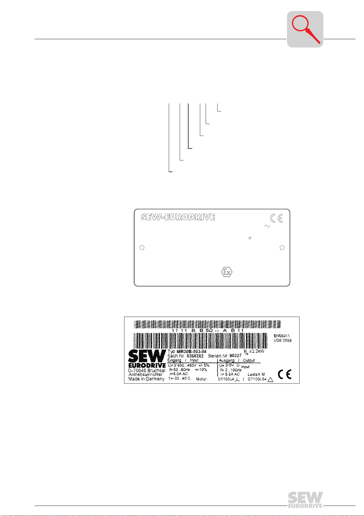
3.1 Type designation, nameplates
Type designation
example
MOVIMOT® nameplate (example)
MO VIMOT MM 22 - 503 - 04
®
KA67DT100L4BMGMM30B/MLA
Typ
010012345.6.00.00
Nr.
2,2 / 50Hz
kW
50Hz V
92/1400
r/min
Kg
15,19
i
Schmierstoff
Type designation, nameplates
B
Ver sion (04 = 3D category)
Connection type
Supply voltage
Version B
Motor rating
Nm
®
Series
Bruchsal/Germany
40110
Nm
Made in Germany
400-460
400-460
V
Ma
MOVIMO T
31054
:1
3 IEC 34
B3
IM
0,99
cos
5,0
A
5,0
A60Hz V
54
IP
GleichrichterBremse
II 3 D T 140°C
Kl.
186 853 5.10
3
02883AEN
F
Electronics
nameplate
(example)
03090AXX
02581AXX
Operating Instructions MOVIMOT® MM..B for Use According to Category 3D
7
Page 8
3
Structure of the inverter unit
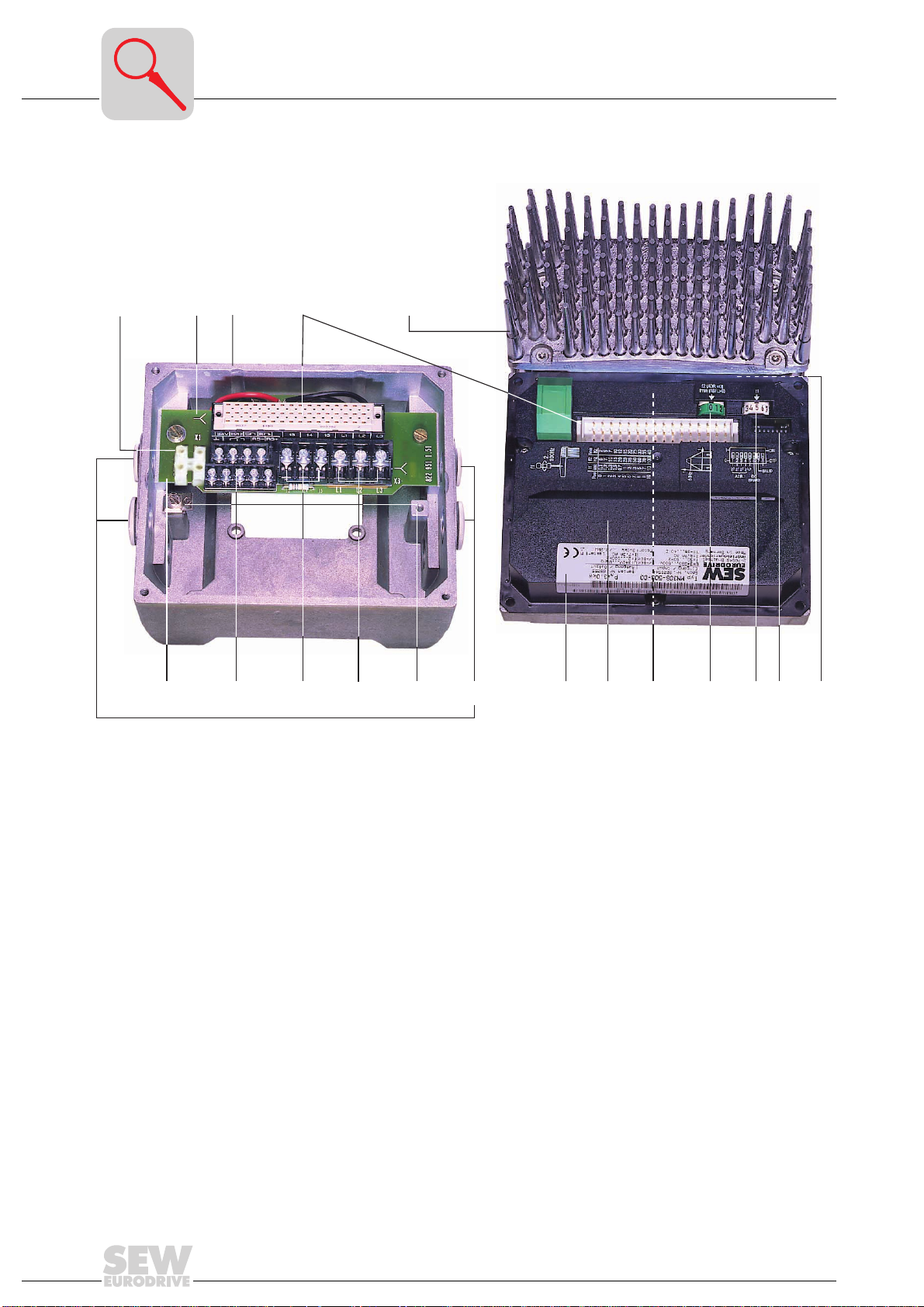
3.2 Structure of the inverter unit
2
18
1
34
5 6 7 8 9 10 111213 141516
®
unit)
02882AXX
Bild 1: Structure of the unit
1 Identification of the circuit type
2 Connection box
3 Connection plug, connection unit with inverter
4 Connection box cover with inverter and heat sink
5 Connection unit with terminals
6 Electronics terminal strip X2
7 Connection of brake coil (X3)
For motors without a brake: Connection of internal braking resistor BW1/BW2 (standard)
8 Power system connection L1, L2, L3 (X3) (suitable for 2 x 4 mm
9 Screws for PE connection y
10 Cable screw fittings MM03B-MM15B: (2 x PG11 and 2 x PG16 / from start of 2000, 2 x M16 and 4 x M25)
(not all visible in picture) MM22B-MM30B: (4 x PG11 and 4 x PG16 / from start of 2000, 4 x M16 and 4 x M25)
11 Electronics nameplat e
12 Safety hood for inverter electronics
13 Setpoint potentiometer f1 (not visible),
accessible from the top of the connection box cover by means of a PG screw fitting
14 Setpoint switch f2 (green)
15 Switch t1 for ramp generator (white)
16 DIP switch S1 for setting the bus address, motor protection, DC braking, PWM frequency
17 Status LED (visible from the top of the connection box cover, see “Status LED” on page 26)
18 Terminals for TH connection (arrangement of terminals varies according to the size of the MOVIMOT
2
)
17
8
Operating Instructions MOVIMOT® MM..B for Use According to Category 3D
Page 9
3.3 Description of the controls
DIP SWITCH S1
S1/..
1 2 3 4 5 6 7 8
ON 2021222
OFF RS-485 address
1) 16 kHz PWM frequency (low-noise)
When DIP SWITCH S1/7 = ON, the units operate with a 16 kHz PWM frequency (low noise) and
switch back in steps to lower pulse frequencies depending on the heat sink temperature.
* Factory setting
3
Description of the controls
Motor protection
deactivated
Motor protection
active *
DC braking
4Q operation *
PWM frequency
1)
16 kHz
PWM frequency
variable
4 kHz fix *
3
No func-
tion
Setpoint
potentiometer f1
Setpoint switch f2
3
4
5
6
7
8
The function of the potentiometer changes depending on the unit’s operating mode .
• Control via terminals: Setpoint f1 (selected by tl. f1/f2 = “0”)
• Control via RS-485: Maximum frequency f
100
f[Hz]
6
5
75
50
25
2
123456789100
max
Pot.position
f
1
02704AEN
The function of the switch changes depending on the unit’s operating mode.
• Control via terminals: Setpoint f2 (selected by tl. f1/f2 = “1”)
• Control via RS-485: Minimum frequency f
Setpoint switch f2
Detent position 0 * 12345678910
Setpoint f2 [Hz] 5 * 7 1015202535506070100
Minimum frequency f
[Hz]
min
2 * 5 7 10 12 15 20 25 30 35 40
min
* Factory setting
Switch t1
3
4
5
6
7
8
For ramp generator
Switch t1
Detent position 01234 5 *678910
Ramp time t1 [s] 0.1 0.2 0.3 0.5 0.7 1 * 2 3 5 7 10
Factory setting
*
Operating Instructions MOVIMOT® MM..B for Use According to Category 3D
9
Page 10
4
Mechanical Installation
4 Mechanical Installation
Before you begin
Installation tolerances
Setting up
MOVIMOT
®
MOVIMOT® may not be installed unless:
• the entries on the name plate of the drive match the mains power supply,
• the drive is undamaged (no damage caused by transport or storage) and
• it is certain that the following requirements have been fulfilled:
– ambient temperatures between -20 °C and +40 °C (remember that the tempera-
ture range of the gear unit may be restricted → operating instructions for the
gear unit),
– no oil, acid, gas, vapors, radiation, etc.,
– installation altitude max. 1000 m above sea level.
Shaft end Flanges
Diametric tolerance in accordance with DIN 748
• ISO k6 at ∅ ≤ 50 mm
• ISO m6 at ∅ > 50 mm
(Center hole in accordance with DIN 332, shape DR)
→ ”MOVIMOT® Geared Motors” catalog, section ”Notes on Dimension Sheets.”
Centering shoulder tolerance in accordance with DIN
42948
• ISO j6 at ∅ ≤ 230 mm
• ISO h6 at ∅ > 230 mm
The MOVIMOT® may only be mounted or installed in the specified mounting position on
a level, vibration-proof and torsionally rigid support structure.
• Thoroughly remove anti-corrosion agents from the shaft ends (use a commercially
available solvent). Do not allow the solvent to penetrate the bearings and shaft
seals – this could cause material damage!
• Carefully align MOVIMOT
®
and the driven machine to avoid placing any unacceptable strain on the motor shafts (observe permissible overhung load and axial thrust
data!).
• Do not butt or hammer the shaft end.
• Use an appropriate cover to protect motors in vertical mounting positions
from accidental entering of objects or fluids ! (Protection cowl C)
• Ensure an unobstructed cooling air supply and that air heated by other units cannot
be drawn in or reused.
• Balance components for subsequent mounting on the shaft with a half key (output
shafts are balanced with a half key).
10
Operating Instructions MOVIMOT® MM..B for Use According to Category 3D
Page 11
5 Electrical Installation
It is essential to comply with the safety notes (see page 5) during installation!
5.1 Installation guidelines
When connecting up, comply with the following ElexV 1 provisions (or other nationally
valid regulations) in addition to the generally applicable installation regulations:
• EN 60 079-14 (“Installation of electrical systems in hazardous areas”)
• EN 50281-1-2 (“Electrical tools and fixtures for use in atmo spheres con taining
flammable dust”)
• DIN VDE 0105-9 (“Operation of electrical systems”)
• DIN VDE 0100 (“Setup of power installations up to 1000 V”)1)
• and provisions specifically relating to the system
Connecting supply system leads
Rated voltage and
frequency
• The rated voltage and frequency of MOVIMOT® must correspond to the data for the
mains supply.
Installation guidelines
1)
5
Selecting the
cables
Permitted line cross
section of the terminals
Conductor end
sleeves
Cable entries
Line protection
Residual-currentoperated circuit
breaker
Contactor switch
contacts
• The cross sections of the cables used must be selected according to the rated current of the unit and the applicable installation regulations.
• The selection of the cable type is based on the applicable installation regulations
and the requirements at the application location.
Power terminals Control terminals
1.0 mm2 – 4.0 mm2 (2 x 4.0 mm2) 0.25 mm2 – 1.0 mm2 (2 x 0.75 mm2)
AWG17 – AWG10 (2 x AWG10) AWG22 – AWG17 (2 x AWG18)
• Use conductor end sleeves without insulating shrouds
(DIN 46228 part 1, material E-CU)
• All cable entries are supplied fitted with a closing plug.
To connect the unit, replac e the req uired nu mbe r of plug s with su itable cable entries
which are fitted with strain relief.
• The cable entries must meet the requirements of EN 50 014, 2nd edition.
• Select the cable entries on the basis of the diameter of the cables used. Please
refer to the documentation provided by the manufacturer of the cable entry for further information.
• Install the line protection at the start of the supply system lead behind the supply
bus junction (
breakers. The fusible rating should be selected in accordance with the cross section
of the cable.
• It is not permissible to use a conventional residual-current-operated circuit breaker
(r.c.c.b.) as a protective device. Universal current-sensitive residual-current-operated circuit breakers (tripping current 300 mA) are permissible as a protective
device. Earth-leakage currents > 3.5 mA may occur during normal operation of the
MOVIMOT
• Contactor switch contacts in utilization category AC-3 to IEC 158 must be used for
switching MOVIMOT
see section 5.4 to section 5.6:
®
.
®
.
F11/F12/F13). Use D, DO, NH or circuit
1. Or other national guidelines
Operating Instructions MOVIMOT® MM..B for Use According to Category 3D
11
Page 12

5
Installation guidelines
IT systems
Connecting
24 V
Conventional
control
(using binary
commands)
Control via
RS-485 interface
Cable screw fittings
DC
supply
• SEW recommends using earth-leakage monitors with a pulse code measuring
process in voltage power systems with a non-earthed star point (IT systems). This
avoids faulty tripping of the earth-leakage monitor due to the earth capacitance of
the inverter.
• The MOVIMOT® power supply should be either from an external 24 VDC voltage or
using the MLA12A options.
• Connect the required electronic control leads
(e.g. CW/STOP, CCW/STOP, setpoint changeover f1/f2).
• Use shielded cables as control leads and route them separately from power current
cables.
With PLC bus master or MLA12A option
• Important: Only ever connect one
• Use twisted pair shielded cables as control leads and route them separately fro m
power current cables.
• All cable entries which are not required must be sealed properly using
suitable closing plugs.
bus master.
12
Operating Instructions MOVIMOT® MM..B for Use According to Category 3D
Page 13

5.2 Protection concept
In order to avoid exceeding the permitted temperature, only operation in accor-
dance with the operating characteristics is permitted (see “Operating characteristics” on page 38)!
• MOVIMOT® units in category 3D are supplied with a temperature switch (TH). The
TH switches off the motor if the winding temperature exceeds the maximum value.
• The switching off process by the TH must be monitored by an independent evaluation unit.
• The independent evaluation unit must be equipped with a base insulation to
securely separated electrical circuits.
• The drive must be disconnected from the supply power system when the TH
trips.
• The TH automatically switches itself back on when the temperature drops
below the maximum value! A restart interlock must prevent the drive from
being energized.
Important: Do not switch the drive back on until the cause of the problem has been
checked. This check must be performed by a trained specialist.
Protection concept
5
In conjunction with
MLA12A
• The unit is supplied with the TH already wired up in conjunction with MLA12A. Consequently, the 24 V power supply of MOVIMOT
and the drive is stopped. At the same time, the ready contact of the MOVIMOT
drops out (ready signal terminals). A restart interlock must prevent the drive
from being energized again automatically when the TH switches back on.
Important: Do not switch the drive back on until the cause of the problem has been
checked. This check must be performed by a trained specialist.
5.3 Operating modes
The following operating modes are permitted with MOVIMOT® units in category 3D:
4Q operation
1Q operation
1. 4Q operation with motors with a mechanical brake
• The brake coil is used as a braking resistor in 4Q operation.
• No external braking resistor is allowed to be connected.
• Regenerative load capacity of the brake coil
2. 1Q operation with motors without a mechanical brake
Important:
Connecting an internal or external braking resistor is not permitted!
®
is interrupted when the TH trips
(see page 37)
®
Operating Instructions MOVIMOT® MM..B for Use According to Category 3D
13
Page 14
5
Connection with binary control
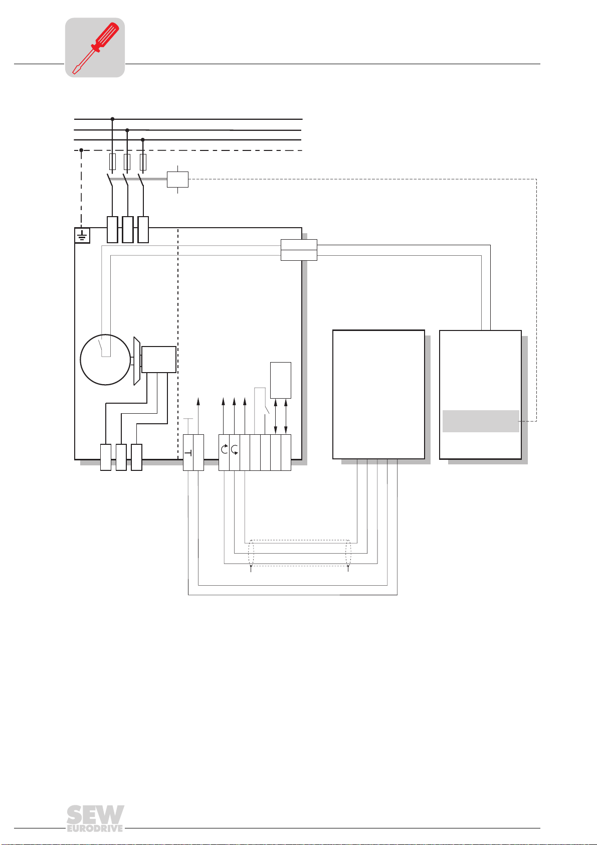
5.4 Connection with binary control
L1
L2
L3
PE
L1
F11/F12/F13
L2
L3
K11
TH
TH
ϑ
14
blue
15
BMG
brake
Terminal Ready signal
Terminal setpoint change
Terminal C CW/Stop
Terminal C W/Stop
Incoming electronics
supply voltage
L
R
24V
1) The independent evaluation unit must have a base insulation to securely separated electrical
circuits.
f1/f2
y
RS-485
K1
RS-
K1a
K1b
Metal cable
entry
RS+
External
control
y
Independent
evaluation unit
restart interlock
1)
with
02844AEN
M
3~
red
white
13
14
Operating Instructions MOVIMOT® MM..B for Use According to Category 3D
Page 15
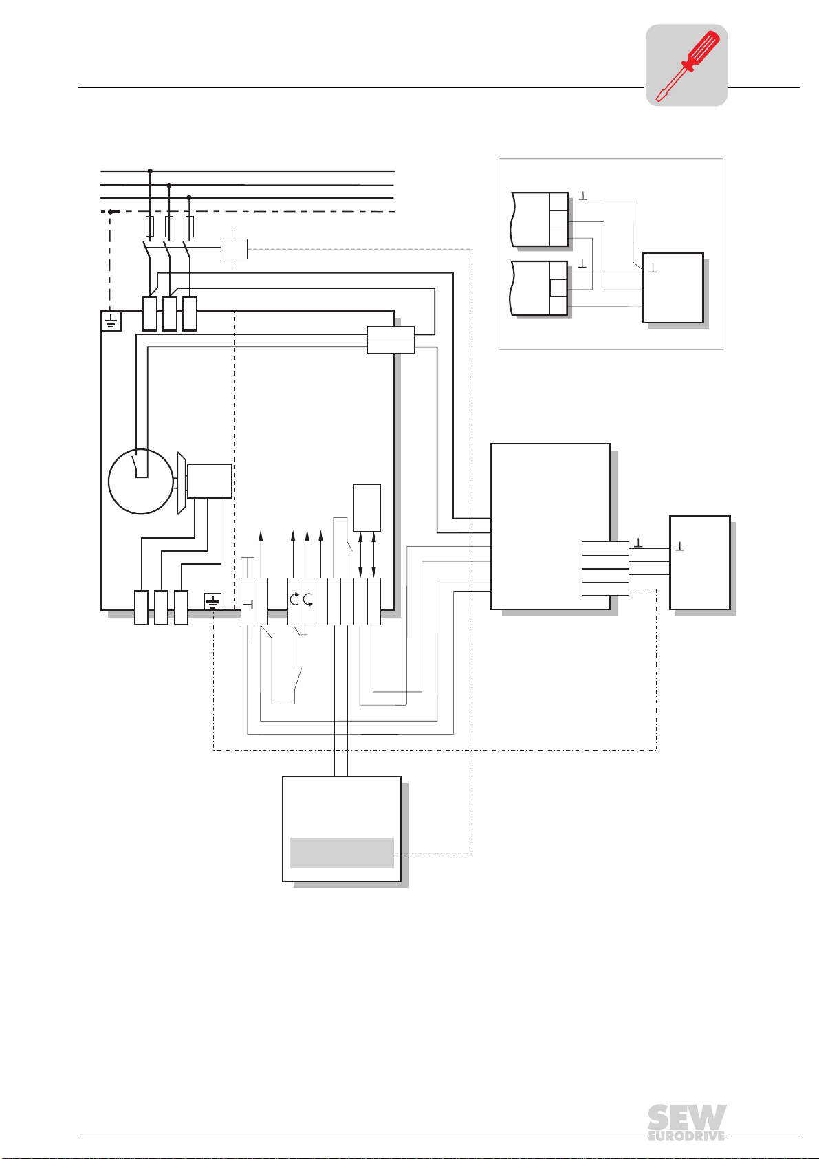
5.5 Connection with MLA12A option
Connection with MLA12A option
5
L1
L2
L3
PE
Connecting several MLA12A units:
4
AI-
MLA12A
3
AI+
2
F11/F12/F13
K11
4
AI-
3
AI+
2
L1
L2
L3
TH
TH
ϑ
M
3 ~
red
13
BMG
brake
yellow
Terminals Ready signal
Terminal Setpoint change
Terminal CC W/Stop
Terminal CW/Stop
Incoming electronics
supply voltage
white
blue
L
R
14
15
24V
f1/f2
K1
K1a
K1b
RS-485
RS-
RS+
yellow
MLA12A
MLA12A
Setpoint converter
with 24V
supply
x10
x9
x8
x7
x6
x5
DC
4
3
2
1
AIAI+
PE
-
PLC
+
PLC
-
+
Start/Stop
Relay
monitoring
with
restart interlock
green
red
orange
blue
02845AEN
Operating Instructions MOVIMOT® MM..B for Use According to Category 3D
15
Page 16

5
Connection with RS-485 bus mode
5.6 Connection with RS-485 bus mode
L1
L2
L3
PE
L1
F11/F12/F13
L2
L3
K11
TH
TH
ϑ
M
3~
red
13
BMG
brake
Terminals Ready signal
Terminal Setpoint change
Terminal CCW/Stop
Terminal CW/Stop
Incoming electronics
supply voltage
white
blue
L
R
14
15
24V
Both directions
of rotation
enabled
Potential compensation with the RS-485 master
1) The independent evaluation unit must have a base insulation to safely separated
electrical circuits.
f1/f2
cable entries
K1
K1a
K1b
Metal-
RS-485
RS-
RS+
y
RS-485
bus master
RS-485
y
Independent
evaluation unit
with
restart interlock
1)
02849AEN
16
Operating Instructions MOVIMOT® MM..B for Use According to Category 3D
Page 17

6 Startup
6.1 Important startup instructions
Important startup instructions
I
6
00
• It is essential to comply with the safety notes (see page 5) during startup!
• Disconnect MOVIMOT
the terminal box cover.
• Before startup, make sure that
– the drive is not damaged and
– all protective covers have been fitted correctly.
• MOVIMOT
unit. As a result, the parameter settings are fixed.
• Use CW/STOP or CCW/STOP for jog mode.
• A minimum switch-off time of 2 seconds must be maintained for the supply system
contactor K11.
®
is optimally adapted to the motor by means of parameters stored in the
®
from the supply system before removing/replacing
Operating Instructions MOVIMOT® MM..B for Use According to Category 3D
17
Page 18

6
00
I
1
ON
432
6
7
5
Startup with binary control
6.2 Startup with binary control
Check connection
Set the DIP
switches
Set the first speed
1. Check MOVIMOT® to see that it is connected correctly (see “Connection with binary
control” on page 14).
2. Make sure DIP switches S1/1 – S1/4 are set to OFF (= address 0).
3. Check the setting for 4Q operation / 1Q operation (DIP switch S1/6 = Off).
ON
1
2
543
6
8
7
02764AEN
to 2.
ON
to 3.
1
2
543
6
8
7
4. Set the first speed with setpoint potentiometer f1 (active when tl. f1/f2 = “0”)
(factory setting: approx. 50 Hz).
100
f[Hz]
6
5
75
50
25
f
1
2
123456789100
Pot.position
Set the second
speed
3
4
5
6
7
8
Setting the ramp
time
3
4
5
6
7
8
Fig. 2: Frequency response of setpoint potentiometer f1
02704AEN
• The first speed is infinitely variable and can be set by using the setpoint
potentiometer f1 which is accessible externally.
• The opening above potentiometer f1 must be closed properly during operation by means of the supplied closing plug. This is the only way in which
explosion-protection can be guaranteed.
• The plug must not be removed, even for adjusting the speed, unless there is
no dangerous dust/air mixture present.
5. Set the second speed with switch f2 (active when tl. f1/f2 = “1”).
Switch f2
Detent position 0 * 12345678910
Setpoint f2 [Hz] 5 * 7 1015202535506070100
* Factory setting
6. Set the ramp time with switch t1.
Switch t1
Detent position 0 1234 5 *678910
Ramp time t1 [s] 0.1 0.2 0.3 0.5 0.7 1 * 2 3 5 7 10
* Factory setting
7. Put on the terminal box cover and secure with bolts.
8. Make sure the cover has a seal and fit the cover back in.
18
Operating Instructions MOVIMOT® MM..B for Use According to Category 3D
Page 19

Startup with binary control
I
6
00
Important
The opening above potentiometer f1 must be closed properly during operation by
means of the supplied closing plug. This is the only way in which explosion protection may be guaranteed. The plug must not be removed, even for adjusting the
speed, unless there is no dangerous dust/air mixture present.
9. Switch on the 24 V
control voltage and supply system.
DC
Inverter response according to the terminal level
Network 24 V f1/f2 CW/STOP CCW/STOP Status LED Inverter response
00XXXOffInverter off
10XXXOffInverter off
11X00YellowStop
11010GreenClockwise with f1
11001Green
11110GreenClockwise with f2
11101Green
11X11YellowStop
Key:
0 = No voltage
1 = Voltage
X = Any
Counterclockwise
with f1
Counterclockwise
with f2
Evaluation of the
TH
Functional check
• The TH switch-off must be monitored by an independent eval uation unit.
• The drive must be disconnected from the power supply system when the TH trips.
• The TH automatically switches itself back on when the temperature drops below the
maximum value! An automatic restart must be prevented (restart interlock).
• Do not switch the drive back on until the cause of the problem has been checked.
This check must be performed by a trained specialist.
Check the brake for proper function when brake motors are used. This step will
prevent brake friction and the associated generation of excess heat.
Operating Instructions MOVIMOT® MM..B for Use According to Category 3D
19
Page 20

6
00
I
1
ON
2
6
7
5
Startup with the MLA12A option
6.3 Startup with the MLA12A option
Checking connection
Set the DIP
switches
Setting the minimum frequency
3
4
5
6
7
8
Setting the ramp
time
3
4
5
6
7
8
Setting the maximum speed
1. Check to see that MOVIMOT® is connected correctly (see “Connection with
MLA12A option” on page 15).
2. Set DIP switch S1/1 (on MOVIMOT® ) to ON (= address 1).
3. Check the setting for 4Q operation / 1Q operation (DIP switch S1/6 = Off).
ON
to 2.
1
2
4. Set the minimum frequency f
55443
6
8
7
with switch f2
min
to 3.
Switch f2
Detent position 0 * 12345678910
Minimum frequency f
[Hz]
min
2 * 5 7 10 12 15 20 25 30 35 40
ON
1
2
3
6
8
7
02765AEN
* Factory setting
5. Set the ramp time with switch t1.
Switch t1
Detent position 01234 5 *678910
Ramp time t1 [s] 0.10.20.30.50.7 1 *235710
* Factory setting
6. Replace terminal box cover and secure with bolts.
7. Set the required maximum speed using setpoint potentiometer f1.
100
f[Hz]
6
5
75
50
f
1
Important
Selecting the direction of rotation
25
2
123456789100
Pot.position
02704AEN
The opening above potentiometer f1 must be closed properly during operation by
means of the supplied closing plug. This is the only way in which explosion protection may be guaranteed. The plug must not be removed unless there is no dangerous dust/air mixture present.
8. Make sure the cover has a seal and fit it back in place.
9. Select the sign (direction of rotation) for the analog input (tl. 2 and tl. 3) on the
MWA12A option using switch S1.
S1 S2
Clockwise OFF N.C.
Counterclockwise ON N.C.
10. Switch on the voltage.
20
Operating Instructions MOVIMOT® MM..B for Use According to Category 3D
Page 21

Startup with the MLA12A option
I
6
00
Control
Setpoint stop
function
Evaluation of the
TH
MOVIMOT® is controlled from f
min
to f
using the analog signal at terminal 2 and ter-
max
minal 3.
[Hz]
5
4
3
f
min
(2 Hz)
Output frequency
1
0
0 0,2 0,4
• The unit is supplied with the TH already wired up in conjunction with the MLA12A
option. Consequently, the 24 V power supply of MOVIMOT
TH trips and the drive is stopped. At the same time, the “Ready contact” of
MOVIMOT
®
drops out (“Ready contact” terminals). An automatic restart must be
0,6
Setpoint
0,8 1
®
is interrupted when the
[mA]
02846AEN
secured by evaluation of the ready contact!
• Do not switch the drive back on until the cause of the problem has been checked.
This check must be performed by a trained specialist.
Functional check
Check proper brake function when using brake motors. This step will prevent
brake friction and the associated generation of excess heat.
Operating Instructions MOVIMOT® MM..B for Use According to Category 3D
21
Page 22

6
00
I
6
7
5
24V
L
R
L
R
24V
L
R
24V
L
R
24V
Startup with RS-485 bus operation
6.4 Startup with RS-485 bus operation
Checking connection
Setting the RS-485
address
* Factory setting
Setting the minimum frequency
3
4
5
6
7
8
Setting the ramp
time
3
4
5
6
7
8
1. Check to see that MOVIMOT® is connected correctly (see “Connection with RS-485
bus mode” on page 16).
2. Set the correct RS-485 address on DIP switches S1/1 – S1/4
Address - * 1 2 3 4 5 6 7 8 9 10 11 12 13 14 15
S1/1 OFF ON OFF ON OFF ON OFF ON OFF ON OFF ON OFF ON OFF ON
S1/2 OFF OFF
S1/3 OFF OFF OFF OFF
S1/4 OFF OFF OFF OFF OFF OFF OFF OFF
ON ON OFF OFF ON ON OFF OFF ON ON OFF OFF ON ON
ON ON ON ON OFF OFF OFF OFF ON ON ON ON
ON ON ON ON ON ON ON ON
3. Check the setting for 4Q operation / 1Q operation (DIP switch S1/6 = Off).
ON
to 3.
1
2
4. Set the minimum frequency f
with switch f2
min
Switch f2
Detent position 0 * 12345678910
Minimum frequency f
2 * 5 7 10 12 15 20 25 30 35 40
min
5. Set the ramp time with switch t1 unless it is specified via RS-485.
Switch t1
Detent position 01234 5 *678910
Ramp time t1 [s] 0.10.20.30.50.7 1 *235710
543
6
8
7
02766AEN
* Factory setting
* Factory setting
Enabling the direction of rotation
6. Check whether the required direction of rotation is enabled.
Terminal R Terminals L Meaning
Activated Activated
a)
• Both directions of rotation are enabled
Activated Not activated
b)
• Only clockwise direction of rotation is enabled
• Setpoint entries for counterclockwise lead to the drive
being stopped
Not activated Activated
c)
• Only counterclockwise direction of rotation is enabled
• Setpoint entries for clockwise lead to the drive being
stopped
Not activated Not activated
d)
• Unit is blocked or the drive is stopped
22
Operating Instructions MOVIMOT® MM..B for Use According to Category 3D
Page 23

Startup with RS-485 bus operation
7. Replace terminal box cover and secure with bolts.
I
6
00
Setting the maximum speed
Important:
Evaluation of the
TH
8. Set the required maximum speed using setpoint potentiometer f1.
100
f[Hz]
6
5
75
50
25
f
1
2
123456789100
Pot.position
02704AEN
The opening above potentiometer f1 must be closed properly during operation by
means of the supplied closing plug. This is the only way in which explosion protection may be guaranteed. The plug must not be removed unless there is no dangerous dust/air mixture present.
9. Make sure the cover has a seal and fit cover back in.
10. Switch on the voltage.
• The TH switch-off must be monitored by an independent eval uation unit.
• The drive must be disconnected from the power suuply system when the TH trips.
• The TH automatically switches itself back on when the temperature drops below the
maximum value! An automatic restart must be prevented (restart interlock).
• Do not switch the drive back on until the cause of the problem has been checked.
This check must be performed by a trained specialist.
Functional check
Check proper brake function when brake motors are used. This step will prevent
brake friction and the associated generation of excess heat.
Operating Instructions MOVIMOT® MM..B for Use According to Category 3D
23
Page 24

6
00
I
Serial communication
6.5 Serial communication
• The control (e.g. PLC) is the master, MOVIMOT® is the slave.
• 1 start bit, 1 stop bit and 1 parity bit (even parity) are used.
• Transmission conforms to the SEW-MOVILINK
Message
structure
Key
Idle = Start pause at least 3.44 ms
SD1 = Start delimiter (start character) 1: Master → MOVIMOT
SD2 = Start delimiter (start character) 2: MOVIMOT® → Master: 1D
ADR = Address 1 – 15
TYPE = User data type
PDU = User data
BCC = Block check character: XOR all bytes
of 9600 baud.
Group address 101 – 115
254 = Point-to-point
255 = Broadcast
TYPE
03
hex
83
hex
05
hex
85
hex
Transfer
variant
Cyclical 2 words
Acyclical 2 words
Cyclical 3 words
Acyclical 3 words
Process
data length
®
protocol with a fixed transfer rate
02754AEN
®
: 02
hex
hex
User data
Control word / Speed [%]
Status word 1 / Output current
Control word / Speed [%] / Ramp
Status word 1 / Output current / Status word 2
24
Note:
If the “cyclic” type is selected, MOVIMOT® expects the next bus activity after maximum
one second (master protocol). If this bus activity is not detected, MOVIMOT
®
rests au-
tomatically (time-out monitoring).
There is no time-out monitoring if the “acyclical” type is selected.
Operating Instructions MOVIMOT® MM..B for Use According to Category 3D
Page 25

User data master → Slave
15
14
13
12
11
10
I
Serial communication
6
00
Basic control block
9
8
7
5
6
4
2
3
0
1
Control word
Setpoint
Ramp *
* only with 3 word protocol
Signed percentage / 0.0061 % -80 % / 0.0061 % = -13115 = CCC5Example:
Time from 0 to 50 Hz in ms (range: 100...10000 ms) 2.0 s = 2000 ms = 07D0Example:
User data slave → Master
15
14
State of unit/fault number
Status word 1
Actual current
value
0 = inverter not ready
2 = no enable
4 = enabledV/f-controlled
13
not assigned
12 11
10 9 8
16 Bit signed integer x 0.1% I
Example: 0320 = 800 x 0.1% I = 80% I
h exNN
6
7
N
"1" =
Reset
5
4
3
not assigned
21
0
"1 1 0" = release,
otherwise stop
hex
hex
02758AEN
Controller enabled = "1"
Unit ready = "1"
PO data enabled = "1"
reserved
reserved
Error/Warning = "1"
reserved
reserved
Status word 2*
* (only with 3 word protocol
Controller enabled = "1"
Unit ready = "1"
PO-data enabled = "1"
reserved
reserved
Error/Warning = "1"
reserved
reserved
A1 (brake)
A2 (ready)
E1 (CW)
E2 (CCW)
E3 (setpoint value f2)
reserved 0
reserved 0
reserved 0
)
02760AEN
The following manuals provide more detailed information about startup with RS485 bus operation and about the MOVILINK
Manual and MOVILINK
®
Unit Profile, Communication and Fieldbus Interfaces.
®
unit profile: MOVIMOT® System
Operating Instructions MOVIMOT® MM..B for Use According to Category 3D
25
Page 26

7
Status LED
7 Operation and Service
7.1 Status LED
Status LED
7.2 Status LED messages
The 3-color LED indicates the operating and er ro r sta te s.
Color Operational status Description
- Off Not ready to operate No 24 V power supply
Yellow
Yellow
Green/
yellow
Green Steady light Unit enabled Motor operating
Green Steady, flashing rapidly Current limit active Drive has reached the current limit
Red flashing twice, pause Fault 07 DC link voltage too high
Red flashing 3x, pause Fault 11 Excessive temperature in output stage
Red flashing 4x, pause Fault 84 Excessive temperature in motor
Red flashing 5x, pause Fault 89 Excessive temperature in brake
Red flashing 6x, pause Fault 06 Mains phase fault
Steady flashing Not ready to operate Self-test phase active or 24 V power supply
present but supply system voltage not OK
Steady light Ready to operate but unit
blocked
Flashing with alternating colors
Ready to operate but timeout Communication via RS-485 interrupted
24 V power supply and power system supply
OK, but no enable signal
02600AEN
26
Operating Instructions MOVIMOT® MM..B for Use According to Category 3D
Page 27

List of errors
7.3 List of errors
Error codes can be evaluated by communicating with the external control using the MOVILINK® profile1) or by
means of the status LED
Errors Cause/Remedy
Communication timeout
(motor stops without error code)
DC link voltage too low, supply system off detected
(motor stops without error code)
Error code 06
Phase fault
Error code 07
DC link voltage
too high
Error code 11
Thermal overload of the output
stage or internal unit fault
Error code 84
Thermal overload of motor
Error code 89
Thermal overload of brake coil
or brake coil defective
(see page 26)
1)
a) No connection ⊥, RS+, RS- between MOVIMOT® and RS-485 master.
b) EMC effects
c) Incorrect type (cyclical) in acyclical protocol
Check supply system leads and supply voltage for interruption.
Motor restarts automatically as soon as the supply voltage reaches normal values.
Check the supply system leads for phase fault. Reset the fault by switching off the
24 V
a) Ramp time too short → Increase ramp time
b) Faulty connection between brake coil and braking resistor
c) Incorrect internal resistance brake coil / braking resistor
d) Thermal overload in braking resistor
Reset error by switching off the 24 V
• Clean heat sink
• Reduce ambient temperature
• Prevent heat accumulation
• Reduce load on drive
Reset error by switching off the 24 V
• Reduce ambient temperature
• Prevent heat accumulation
• Reduce load on the motor
• Increase speed
Reset error by switching off the 24 V
• Extend set ramp time
• Inspect brake (See “Inspection and maintenance of the brake” on page 31)
• Contact SEW service
Reset error by switching off the 24 V
.
Check the connection, in particular the ground, and repair.
Check the shielding of the data cables and improve if necessary.
Time between the individual messages >1 s for protocol type
“cyclical”. Shorten message cycle or select “acyclical”.
supply voltage or use MOVILINK
DC
→ Check connection between braking resistor and brake coil. Correct if necessary.
→ Check internal resistance of brake coil / braking resistor (see page 37)
→ Wrong size of braking resistor selected
®1)
supply voltage or use MOVILINK
DC
supply voltage or use MOVILINK
DC
supply voltage or use MOVILINK
DC
supply voltage or use MOVILINK
DC
®1)
®1)
®1)
®1)
7
1) See the "MOVILINK® Unit Profile, Communication and Fieldbus Interfaces” manual for detailed information about
communication.
If you require assistance from our customer service staff, please state the following:
• Nameplate data
• Time and accompanying circumstances of error
• Type and extent of error
• Presumed cause
Operating Instructions MOVIMOT® MM..B for Use According to Category 3D
27
Page 28
8
Inspection and maintenance periods
8 Inspection and Maintenance
Notes:
• Only use genuine spare parts in accordance with the valid spare parts list!
• Important – Danger of burns: Motors can become very hot during operation!
• The IP enclosure of the housing must be maintained in order to ensure protection against explosions. It is therefore very important to make sure that the
housing parts are assembled correctly in accordance with the spare parts list
for all maintenance and inspection work. Elastomer and plastic seals must be
replaced with genuine spare parts.
8.1 Inspection and maintenance periods
Frequency
depending on loading conditions: every 2 to 4 years
(The wear periods are affected by many factors and may be
short. Calculate the required inspection/maintenance intervals
individually in accordance with the project planning documents.)
every 10,000 hours of operation Motor
variable
(depending on external factors)
Unit/unit
component
Brake
What to do?
• Inspect the brake
(working air gap, brake disk, pressure plate, carrier / gearing, pressure rings)
• Remove abraded matter
• Inspect the moto r
(fit new ball bearings/oil seal)
• Clean the cooling air passages
• Touch up or renew the anticorrosion
coating
Checks following
maintenance or
repair work
Perform a safety and functional check after all maintenance or repair work. This check
should be the same as the functional check described for startup.
Perform another routine test prior to startup if you have rep laced any parts on the m otor
which may affect its explosion-proof qualities.
28
Operating Instructions MOVIMOT® MM..B for Use According to Category 3D
Page 29

Inspection and maintenance work on the motor
8.2 Inspection and maintenance work on the motor
10
9
8
4
5
7
6
8
12
11
15
3
2
1
Fig. 3: Example: motor DFT.. MM..
1Circlip
2 Oil flinger
3 Oil seal
4 Screw plug
5 Drive end bearing
shield
6 Circlip
7 Ball bearing
8 Circlip
9 Rotor
10 Nilos ring
11 Ball bearing
13
16
14
12 Equalizing ring
13 Stator
14 Non-drive end bearing
shield
15 Hexagon screw
16 V ring
20
19
18
17
02575AXX
17 Fan
18 Circlip
19 Fan guard
20 Housing screw
Operating Instructions MOVIMOT® MM..B for Use According to Category 3D
29
Page 30

8
Inspection and maintenance work on the motor
Inspecting the
motor
(Fig. 3)
1. Important: Interrupt power supply to MOVIMOT®, safeguarding it against unintentional power-up.
2. Remove proximity sensor NV16 / NV26 if fitted.
3. Remove the flange cover or fan guard (19).
4. Remove the hexagon head screws (15) from the drive end bearin g shield (5) and the
non-drive end bearing shield (14), releas e the stator (13) from the drive end bearing
shield.
5. a) Motors with a brake:
– open the terminal box cover, remove brake cable from terminals
– push the non-drive end bearing shield and the brake off the stator
and carefully lift them off (if necessary, run the brake cable along with
trailing wire)
b) Pull the stator back by approx. 3 to 4 cm.
6. Visual check:
Are there traces of gear oil or condensation inside the stator?
– no, continue with 9.
– if there is moisture, continue with 7.
– if there is gear oil, have the motor repaired by a specialist workshop
7. a) Geared motors: remove the motor from the gear unit.
b) Motors without a gear unit: remove the drive end flange.
c) Remove the rotor (9).
8. Clean the winding, dry it and check it electrically.
9. Fit new ball bearings (7, 11) (only use approved ball bearings see page 38) .
10. Fit new oil seal (3) in the drive end bearing shield.
11. Reseal the stator seat, reassemble the motor, brake, etc.
Then check gear unit, if applicable
(see the gear unit operating instructions)
.
30
Operating Instructions MOVIMOT® MM..B for Use According to Category 3D
Page 31

Inspection and maintenance of the brake
8.3 Inspection and maintenance of the brake
Parts of the brake are subject to wear during operation. As a result, regular inspection and maintenance are essential.
8
Using the brake
as a working
brake
Using the brake
as a holding
brake
If the brake is used as a working brake, the brake pad wear is the determining factor
governing when to service the brake.
Do not allow the maximum permitted working air gap to be exceeded (see “Work done
until adjustment, working air gap, braking torque of brake” on page 37). The inspection
and maintenance intervals can be calculated on the basis of the work done by the brake
in each braking operation and the entire work done until adjustment (see “Work done
until adjustment, working air gap, braking torque of brake” on page 37).
To do this, please calculate the work do ne in ea ch brak ing opera tion indiv idually in a ccordance with the project planning documents. Check the brake at the latest when it has
performed the amount of work until reset at which point an adjustment is due.
The following parts of the brake are subject to wear and should be r eplaced if necessary
(see Fig. 4):
• Brake disk (7)
• Annular spring (6)
• Pressure plate (8)
• Pressure rings and counter springs (10 b, c)
• Brake springs (11)
• Also replace the self-locking hexagon nuts (10e) and the rubber sealing collar (5)
after repeated disassembly/assembly.
Brakes used as holding brakes are only subject to a small amount of lining wear. However, their mechanical transmission elements must also be checked for wear.
Operating Instructions MOVIMOT® MM..B for Use According to Category 3D
31
Page 32

8
Inspection and maintenance of the brake
9
8
7
6
23
5
23
4
3
2
1
a
Fig. 4: Type BMG 05 – BMG 4
1 Motor with brake bearing end
shield
2 Carrier
3 Circlip
4 Niro disk (only BMG)
5 Rubber sealing collar
6 Annular spring
7 Brake disk
8 Pressure plate
22
21
e
10
c
b
17
16
15
14
13
12
11
9 Damping plate
10a Stud (3 pcs.)
10b Counter spring
10c Pressure ring
10e Hexagon nut
11 Brake spring
12 Brake coil body
13 Sealing washer
14 Dowel pin
19
18
20
02900AXX
15 Releasing lever with hand lever
16 Stud (2 pcs.)
17 Conical coil spring
18 Setting nut
19 Fan
20 Circlip
21 Fan guard
22 Housing screw
23 Clamping strap
32
Operating Instructions MOVIMOT® MM..B for Use According to Category 3D
Page 33

Inspection and maintenance of the brake
8
Inspecting the
brake
(Fig. 4 + Fig. 5)
Checking the
brake disk
Setting the working
air gap
1. Interrupt MOVIMOT® power supply, safeguarding it against unintentional
starting.
2. Remove the following:
– Proximity sensor NV16 / NV26, if fitted
– Flange cover or fan guard (21)
3. Remove the clamping straps (23) and move the rubber sealing collar (5).
Remove any abraded residue with vacuum.
4. Measure the brake disk (7):
If the brake disk is ≤ 9 mm:
Replace brake disk
5. Measure the working air gap A
– with feeler gauge at three points between thepressure plate and the damping
plate (9)offset by approx. 120°.
6. Tighten the hexagon nuts (10e) until working air gap is set correctly
7. Fit rubber sealing collar and clamping straps back in place and re-install removed
parts.
(see page 34)
(see Fig. 5).
.
(see page 37)
A
.
Fig. 5: Measuring the working air gap
02577AXX
Operating Instructions MOVIMOT® MM..B for Use According to Category 3D
33
Page 34

8
Inspection and maintenance of the brake
Installing new
brake disk
(Fig. 4 + Fig. 5)
When installing a new brake disk, inspect the other removed parts as well and replace,
if necessary.
®
1. Interrupt power supply to MOVIMOT
tional starting.
2. Remove the following:
– proximity sensor NV16 / NV26, if fitted
– flange cover or fan guard (21), circlip (20) and fan (19)
3. Remove the clamping straps (23) and rubber sealing collar (5) .
Remove the manual brake release: setting nuts (18), conical coil springs (17), studs
(16), releasing lever (15), dowel pin (14).
4. Unscrew hexagon nuts (10e), carefully pull off the coil body (12) (brake cable!) and
remove brake springs (11).
5. Remove the damping plate (9), pressure plate (8) and brake disk (7) and clean the
brake components.
6. Install new brake disk.
7. Re-assemble the brake components (except for the rubber sealing collar, fan and
fan guard).
Set the working air gap
8. For manual brake release (type HF or HR):
Use setting nuts to set the floating clearance between the conical coil springs
(pressed flat) and the setting nuts
(see page 33 / points 5. to 7.)
(→ Fig. 6)
unit, safeguarding it against uninten-
.
.
Important: This floating clearance is necessary so that the pressure plate can move
up as the brake lining wears.
9. Fit the rubber sealing collar and clamping straps back in pl ace and re-install the dismantled parts.
Note:
The lockable manual brake release (type HF) has already been released if a resistance
is encountered when operating the manual brake release screw.
The self-reengaging manual brake release (type HR) can b e operated with normal hand
pressure.
Important:
In brake motors with self-reengaging manual brake release, the manual brake re-
lease lever must be removed after startup/maintenance. A bracket is provided for
storing it on the outside of the motor.
Brake
BMG 05-1 1.5
BMG 2-BMG4 2
Floating clearance mm
34
Fig. 6
01111AXX
Operating Instructions MOVIMOT® MM..B for Use According to Category 3D
Page 35

Inspection and maintenance of the brake
8
Changing the
braking torque
(Fig. 4 + Fig. 5)
The braking torque can be altered in steps
• by installing different brake springs,
• by changing the number of brake springs.
1. Interrupt power supply to MOVIMOT
tional start.
2. Remove the following:
– proximity sensor NV16 / NV26, if fitted
– flange cover or fan guard (21), circlip (20) and fan (19)
3. Remove the clamping straps (23) and rubber sealing collar (5) .
Remove the manual brake release:
setting nuts (18), conical coil springs (17), studs (16), releasing lever (15), do wel pin
(14).
4. Unscrew the hexagon nuts (10e) and pull off the brake coil body (12) by about 50
mm (caution: brake cable!).
5. Replace or add brake springs (11).
(Position the brake springs symmetrically.)
6. Re-assemble the brake components (except for the rubber sealing collar, fan and
fan guard).
Set the working air gap
7. With manual brake release:
Use setting nuts to set the floating clearance between the conical coil springs
(pressed flat) and the releasing lever
(see page 33 / points 5. to 7.)
(see page 37)
®
unit, safeguarding it against uninten-
.
(→ Fig. 6)
.
Important: This floating clearan ce is necessary so that the pressure plate can move
up as the brake lining wears.
8. Fit the rubber sealing collar back in place and re-install removed parts.
Note:
Install new setting nuts (18) and hexagon nuts (1 0e) if the removal procedure is rep eated! (due to reduction in the self-locking effect of the nuts!)
Operating Instructions MOVIMOT® MM..B for Use According to Category 3D
35
Page 36

9
P
i
f
kVA
Hz
n
MOVIMOT® in category 3D
9 Technical data (relating to 4 kHz PWM frequency)
9.1 MOVIMOT® in category 3D
MOVIMOT® type
Output power
Connection voltages
Approved range
Supply frequency
Supply system rated current
(at V
= 400 VAC)
in
Output voltage
Output frequency
Resolution
Operating point
Rated output current I
Motor power
PWM frequency
Current limitation
External braking resistor
P
V
f
in
I
in
U
f
A
N
P
I
max
R
N
in
A
mot
min
MM 03B-
503-04
0.8 kVA 1.1 kVA 1.4 kVA 1.8 kVA 2.2 kVA 2.8 kVA 3.8 kVA
1.0 AAC 1.3 AAC 1.6 AAC 1.9 AAC 2.4 A
1.2 AAC 1.6 AAC 2.0 AAC 2.5 AAC 3.2 A
0.25 kW 0.37 kW 0.55 kW 0.75 kW 1.1 kW 1.5 kW 2.2 kW
MM 05B-
503-04
MM 07B-
503-04
MM 11B-
503-04
3 x 400 VAC / 415 VAC / 460 V
Vin = 400 VAC -5 %...460 VAC +5 %
50 Hz – 60 Hz ±10 %
0 – V
in
2...100 Hz
0.01 Hz
400 V at 50 Hz / 100 Hz
41) / 8 / 12 / 162)kHz
Motor: 160 % at V, 150 % at ∆
Regenerative: 160 % at V, 150 % at ∆
Not permitted
MM 15B-
503-04
AC
AC
MM22B-
503-04
AC
3.5 A
4.0 A
Interference immunity Complies with EN 50082 – Parts 1+2
Emitted interference
Ambient temperature
Enclosure
(select and specify with order)
q
to EN 55011 and EN 55014, complies with EN 50081 – Part 2
amb
In accordance with limit value class A
-20 °C...+40 °C
IP54, IP55, IP65
Operating mode DB (EN 60149-1-1 and 1-3)
Type of cooling (DIN 41 751) Self-cooling
Altitude
Ext. power supply to control
electronics
Binary inputs
h ≤ 1000 m (P
Tl. 24 V V = +24 V ± 25 %
Isolated by opto-coupler, PLC-compatible (EN 61131-2)
R
≈ 3.0 kΩ, IE ≈10 mA, sampling interval ≤ 5 ms
i
reduction: 1 % per 100 m up to max. 2000 m)
N
≤ 250 mA
I
E
Signal level 13 V...+30 V = “1” = Contact closed
-3 V...+5 V = “0” = Contact open
Control functions Tl. R
Output relay
Contact data
Tl. L
Tl.f1/f2
Tl. K1a
Tl. K1b
“0” = Setpoint 1 / “1” = Setpoint 2
24 V
DC
CW/STOP
CCW/STOP
Response time ≤ 10 ms
/ 0.6 ADC / DC11 to IEC 337-1
Signaling function Normally open contact for ready signal
Serial interface
Tl. RS +
Tl. RS -
Max. 32 stations (1 bus master3) + 31 MOVIMOT® units)
Max. cable length: 200 m (for transmission rate: 9600 baud)
RS-485 (to EIA standard)
30 m (for transmission rate: 31250 baud
1) Factory setting
2) 16 kHz PWM frequency (low-noise)
When DIP SWITCH S1/7 = ON, the units operate with a 16 kHz PWM frequency (low noise) and switch back in steps to lower
pulse frequencies depending on the heat sink temperature.
3) Ext. control or option MLA12A
4) Transmission rate of 31250 baud is set automatically for operation with the MLA12A option.
AC
AC
MM 30B-
503-04
5.0 A
5.5 A
4)
)
AC
AC
36
Operating Instructions MOVIMOT® MM..B for Use According to Category 3D
Page 37

Technical data MLA12A option
9.2 Technical data MLA12A option
MLA12A
Part number 823 186 9
Input voltage X9 / X10 380...500 V
Output voltage
Terminals
Analog input:
Serial interface X7 / X8
Enclosure IP65
X6 24 VDC ±25 % (max. 200 mA)
X5 0 V reference potential
Tl. 1 PE
Tl. 2 / tl. 3 0...20 mA
Tl. 4 ⊥ Reference ground for analog input
RS-485 (to EIA standard)
Transmission rate: 9600 / 31250 baud
AC
±10 %
9.3 Regenerative load capacity of brake coil
kVA
i
P
f
Hz
n
9
Load capacity
for
100 % cdf 30 W 57 W 70 W
50 % cdf 39 W 88 W 105 W
25 % cdf 56 W 150 W 175 W
12 % cdf 90 W 270 W 330 W
6 % cdf 150 W 480 W 620 W
Brake coil BMG05/1
(DT71/DT80)
Brake coil BMG2
(DT90)
Brake coil BMG4
(DT 100)
9.4 Work done until adjustment, working air gap, braking torque of brake
Work done
Brake
type
BMG 05 DT 71 60
BMG 1 DT 80 60
BMG 2 DT 90 130
BMG 4 DT 100 130
1) Rated value measured between the red connection (terminal 13) and the blue connection (terminal 15) at
20 °C, temperature-dependent fluctuations in the range of -25 % / +40 % are possible.
2) Please note when checking the working air gap:
Parallelism tolerances on the brake disk may give rise to deviations of ±0.1 mm after a test run.
For
motor size
until adjust-
ment
6
J]
[10
Working air
gap, mm
2)
min.
max.
0.25 0.6
Braking
torque
[Nm]
5.0
4.0
2.5
1.6
1.2
10
7.5
6.0
20
16
10
6.6
5.0
10
30
24
Braking torque settings
Type and number
of springs
Normal Red Normal Red
3
2
-
-
-
6
4
3
3
2
-
-
-
6
4
3
2
6
4
3
2
3
2
6
4
3
2
3
Order numbers
of springs
135 017 X 135 018 8
135 150 8 135 151 6
Resistance
Brake
277 Ω
(230V)
248 Ω
(230V)
216 Ω
(230V)
43.5 Ω
(110V)
1)
Operating Instructions MOVIMOT® MM..B for Use According to Category 3D
37
Page 38

9
P
i
f
kVA
Hz
n
Approved ball bearing types
9.5 Approved ball bearing types
Motor
type
DT 71-80 6204-Z-J 6303-Z-J 6204-Z-J 6203-J 6203-RS-J-C3
DT 90-100 6306-Z-J-C3 6205-J 6205-RS-J-C3
9.6 Operating characteristics
Drive end bearing (AC motor, brake motor)
Flange-
mounted
motor
Geared motor
Foot-mounted
motor
Non-drive end bearing
(foot-mounted, flange-mounted,
geared motors)
AC motor Brake motor
50 Hz
100 Hz
V
n
• The operating characteristics provide information about the torque values with
which MOVIMOT
®
units may be loaded depending on the speed.
• Exceeding these values over long periods gives rise to impermissible heat.
• Brief periods above this value are permitted.
1
S1
0,8
0
,
6
nenn
M/M
0,4
0,2
0
05
0
0 1000 1500 2000 2500 3000
n[1/min]
S3 40%
02847AEN
1
0,8
0
,
6
nenn
M/M
0,4
0,2
0
05
0
0 1000 1500 2000 2500 3000
n[1/min]
S1
S3 40%
02848AEN
38
Operating Instructions MOVIMOT® MM..B for Use According to Category 3D
Page 39

9.7 Declaration by the manufacturer
Declaration by the manufacturer
kVA
i
P
f
Hz
n
9
Operating Instructions MOVIMOT® MM..B for Use According to Category 3D
39
Page 40

We are available,wherever you needus.
Worldwide.
SEW-EURODRIVE right around the globe is
your competent partner in matters of power
transmission with manufacturing and assembly plants in most major industrial countries.
SEW-EURODRIVE GmbH & Co · P.O.Box 30 23 · D-76642 Bruchsal/Germany
Tel. +49-7251-75-0 · Fax +49-7251-75-19 70 · Telex 7 822 391
http://www.SEW-EURODRIVE.com · sew
sew-eurodrive.com
@
 Loading...