

Page 1
Drive Technology \ Drive Automation \ System Integration \ Services
Operating Instructions
Mechatronic Drive System
MOVIGEAR
®
DSC-B
Direct SBus Communication
Edition 04/2010 16889215 / EN
Page 2
SEW-EURODRIVE—Driving the world
Page 3

1 Important Information......................................................................................... 6
1.1 How to use the operating instructions......................................................... 6
1.2 Structure of the safety notes ....................................................................... 6
1.3 Rights to claim under limited warranty ........................................................ 7
1.4 Exclusion of liability..................................................................................... 7
1.5 Copyright notice .......................................................................................... 7
2 Safety Notes ........................................................................................................ 8
2.1 General ....................................................................................................... 8
2.2 Target group ............................................................................................... 8
2.3 Designated use ........................................................................................... 9
2.4 Transportation and storage......................................................................... 9
2.5 Installation................................................................................................. 10
2.6 Electrical connection ................................................................................. 10
2.7 Safe disconnection.................................................................................... 10
2.8 Operation .................................................................................................. 11
3 Unit Design ........................................................................................................ 12
3.1 MOVIGEAR
®
drive unit............................................................................. 12
3.2 Shaft variants ............................................................................................ 13
3.3 Housing mounting ..................................................................................... 14
3.4 Position of the cable entry......................................................................... 15
3.5 Sample nameplate and type designation of drive unit .............................. 16
3.6 MOVIGEAR
®
electronics .......................................................................... 17
3.7 Application options.................................................................................... 19
3.8 Sample nameplate and type designation for electronics .......................... 21
3.9 MOVIGEAR
®
with optional package for wet areas ................................... 23
4 Mechanical Installation..................................................................................... 24
4.1 Installation notes ....................................................................................... 24
4.2 Required tools and resources ................................................................... 24
4.3 Installation prerequisites ........................................................................... 25
4.4 Installing MOVIGEAR
®
............................................................................. 26
4.5 Application options.................................................................................... 29
4.6 Shaft-mounted gear unit with keyway ....................................................... 31
4.7 Shaft-mounted gear unit with TorqLOC
®
(customer shaft without contact shoulder) ................................................ 35
4.8 Shaft-mounted gear unit with TorqLOC
®
(customer shaft with contact shoulder) ..................................................... 40
4.9 Installing the protective cover ................................................................... 45
4.10 Torque arm ............................................................................................... 46
4.11 Tightening torques .................................................................................... 47
4.12 MOVIGEAR
®
with optional package for wet areas ................................... 50
Operating Instructions – MOVIGEAR® DSC-B
3
Page 4

5 Electrical Installation ........................................................................................ 55
5.1 Installation planning considering EMC aspects ........................................ 55
5.2 Installation instructions.............................................................................. 56
5.3 Installation topology (example) ................................................................. 64
5.4 Terminal assignment................................................................................. 65
5.5 Connection of MOVIGEAR
®
..................................................................... 67
5.6 Cable routing and cable shielding............................................................. 68
5.7 Plug connectors ........................................................................................ 75
5.8 Optional plug connector assignment......................................................... 78
5.9 Application options.................................................................................... 91
6 Startup................................................................................................................ 93
6.1 Startup notes............................................................................................. 93
6.2 Description of the DIP switches ................................................................ 94
6.3 Startup of the MOVIGEAR
®
drive units .................................................... 98
6.4 Startup of application option GIO13A ..................................................... 101
6.5 Deactivating DynaStop
7 Operation of MOVITOOLS
7.1 About MOVITOOLS
®
for startup ........................................................ 104
®
MotionStudio .................................................... 105
®
MotionStudio ........................................................ 105
7.2 First steps ............................................................................................... 106
7.3 Connection mode.................................................................................... 108
7.4 Executing functions with the units........................................................... 110
8 Parameters....................................................................................................... 111
8.1 Overview of parameters for command pcb ............................................. 111
8.2 Overview of parameters for application options...................................... 113
8.3 Overview of power section parameters................................................... 115
8.4 Description of command pcb parameters ............................................... 128
8.5 Description of application option parameters.......................................... 130
8.6 Description of power section parameters................................................ 134
9 Operation ......................................................................................................... 162
9.1 Manual mode with MOVITOOLS
®
MotionStudio .................................... 162
9.2 Local mode (only in conjunction with optional plug connector)............... 166
9.3 DynaStop
9.4 Deactivating DynaStop
®
.............................................................................................. 167
®
......................................................................... 168
10 Service ............................................................................................................. 171
10.1 Malfunctions of the mechanical MOVIGEAR
®
drive ............................... 171
10.2 Evaluating error messages ..................................................................... 172
10.3 Switch-off responsess............................................................................. 173
10.4 Resetting error messages....................................................................... 173
10.5 Description of status and operating indicators ........................................ 174
10.6 Unit replacement..................................................................................... 179
10.7 SEW-EURODRIVE Service .................................................................... 180
10.8 Extended storage.................................................................................... 181
10.9 Disposal .................................................................................................. 182
4
Operating Instructions – MOVIGEAR® DSC-B
Page 5

11 Inspection and Maintenance .......................................................................... 183
11.1 Determining the operating hours............................................................. 183
11.2 Inspection and maintenance intervals..................................................... 184
11.3 Lubricant change intervals ...................................................................... 185
11.4 Inspection and maintenance work on the MOVIGEAR
®
drive ................ 186
12 Technical Data and Dimension Sheets ......................................................... 190
12.1 Technical data of MOVIGEAR
®
.............................................................. 190
12.2 Technical data of application options...................................................... 193
12.3 Integrated braking resistor BW1 ............................................................. 195
12.4 Deceleration torques DynaStop
®
............................................................ 196
12.5 Torque characteristics............................................................................. 197
12.6 Surface protection................................................................................... 205
12.7 Package for applications in wet areas .................................................... 207
12.8 Screw connections.................................................................................. 211
12.9 Connection cables .................................................................................. 212
12.10 Mounting positions .................................................................................. 216
12.11 Lubricants ............................................................................................... 218
12.12 Design notes for gear units with hollow shaft and key ............................ 221
12.13 Dimension drawings................................................................................ 223
13 EC Declaration of Conformity .................................................................... 231
14 Address List .................................................................................................... 232
Index................................................................................................................. 242
Operating Instructions – MOVIGEAR® DSC-B
5
Page 6
1
Important Information
How to use the operating instructions
1 Important Information
MOVIGEAR® DSC-B
1.1 How to use the operating instructions
The operating instructions are an integral part of the product and contain important
information for operation and service. The operating instructions are written for all
employees who assemble, install, startup, and service this product.
The operating instructions must be legible and accessible at all times. Make sure that
staff responsible for the plant and its operation, as well as persons who work independently on the unit, have read the operating instructions carefully and understood them.
If you are unclear about any of the information in this documentation, or if you require
further information, contact SEW-EURODRIVE.
1.2 Structure of the safety notes
The safety notes in these operating instructions are designed as follows:
Pictogram SIGNAL WORD
Type and source of danger.
Possible consequence(s) if disregarded.
• Measure(s) to prevent the danger.
Pictogram Signal word Meaning Consequences if
disregarded
Example:
General danger
Specific danger,
e.g. electric shock
DANGER Imminent danger Severe or fatal injuries
WARNING Possible dangerous situation Severe or fatal injuries
CAUTION Possible dangerous situation Minor injuries
NOTICE Possible damage to property Damage to the drive system or its
INFORMATION
Useful information or tip.
Simplifies the handling of the
drive system.
environment
6
Operating Instructions – MOVIGEAR® DSC-B
Page 7

Rights to claim under limited warranty
1.3 Rights to claim under limited warranty
A requirement of fault-free operation and fulfillment of any rights to claim under limited
warranty is that you adhere to the information in the operating instructions. Therefore,
read the operating instructions before you start working with the unit.
Make sure that the operating instructions are available to persons responsible for the
plant and its operation, as well as to person who work independently on the unit. You
must also ensure that the documentation is legible.
1.4 Exclusion of liability
Important Information
1
You must comply with the information contained in the operating instructions to ensure
safe operation of MOVIGEAR
features. SEW-EURODRIVE does not assume liability for injury to persons or damage
to equipment or property resulting from non-observance of these operating instructions.
In such cases, any liability for defects is excluded.
1.5 Copyright notice
© 2010 – SEW-EURODRIVE. All rights reserved.
Copyright law prohibits the unauthorized duplication, modification, distribution, and use
of this document, in whole or in part.
®
and to achieve the specified product and performance
Operating Instructions – MOVIGEAR® DSC-B
7
Page 8

2
2 Safety Notes
2.1 General
Safety Notes
General
The following basic safety notes must be read carefully to prevent injury to persons and
damage to property. The operator must ensure that the basic safety notes are read and
observed. Ensure that persons responsible for the system and its operation, as well as
persons who work independently on the unit, have read through the operating instructions carefully and understood them. If you are unclear about any of the information in
this documentation, please contact SEW-EURODRIVE.
Never install or start up damaged products. Submit a complaint to the shipping company
immediately in the event of damage.
During operation, MOVIGEAR
parts as well as hot surfaces, depending on their enclosure.
Removing covers without authorization, improper use as well as incorrect installation or
operation may result in severe injuries to persons or damage to property.
Refer to the documentation for additional information.
®
drive units can have live, bare and movable or rotating
2.2 Target group
Only qualified electricians are authorized to install, startup or service the units or
correct unit faults (observing IEC 60364 or CENELEC HD 384 or DIN VDE 0100 and
IEC 60664 or DIN VDE 0110 as well as national accident prevention guidelines).
Qualified personnel in the context of these basic safety notes are: All persons familiar
with installation, assembly, startup and operation of the product who possess the
necessary qualifications.
Any activities regarding transportation, storage, operation, and disposal must be carried
out by persons who have been instructed appropriately.
8
Operating Instructions – MOVIGEAR® DSC-B
Page 9
2.3 Designated use
MOVIGEAR® drive units are components intended for installation in electrical systems
or machines.
In case of installation in machines, startup of the MOVIGEAR
designated operation) is prohibited until it is determined that the machine meets the
requirements stipulated in the EC Directive 2006/42/EC (machine directive).
Startup (i.e. the start of designated use) is only permitted under observance of the
EMC (2004/108/EC) directive.
MOVIGEAR
95/EC. The standards given in the declaration of conformity are applied to the
MOVIGEAR
You must observe the technical data and information on the connection requirements
as provided on the nameplate and in the documentation.
2.3.1 Safety functions
The MOVIGEAR
are described and expressly permitted.
Safety Notes
Designated use
®
drive units (i.e. start of
®
drive units comply with the regulations of the Low Voltage Directive 2006/
®
drive units.
®
drive units may not perform safety functions unless these functions
2
2.3.2 Hoist applications
MOVIGEAR
MOVIGEAR
performed a risk assessment. For further information, consult the information in the
documentation.
®
drive units must not be used for hoist applications.
®
drive units may only be used for inclining tracks after the operator has
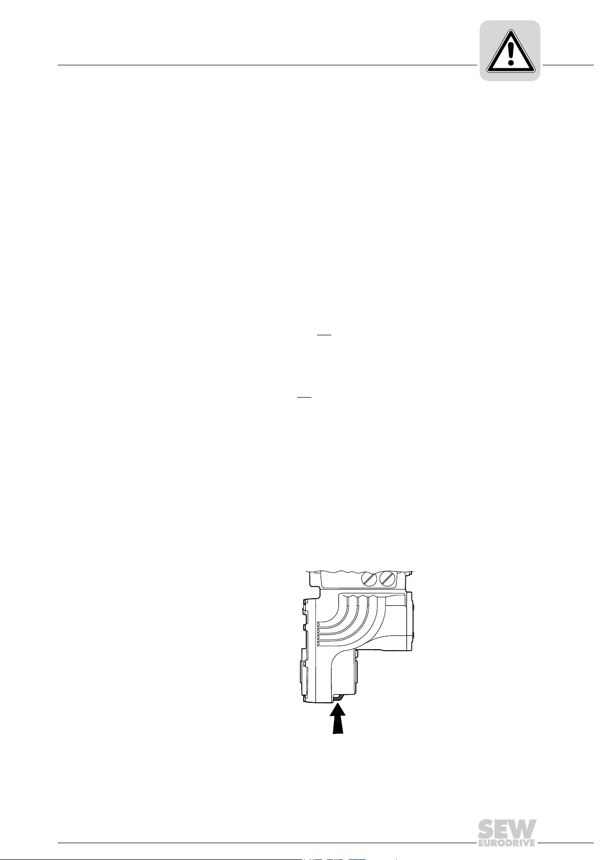
2.4 Transportation and storage
You must observe the notes in the documentation regarding transportation, storage and
proper handling. Use suitable, sufficiently rated handling equipment (e.g. rope guides)
if required. Do not attach any additional loads. Observe climatic conditions in accordance with the documentation.
The following figure shows the eyebolt of MOVIGEAR
®
:
Operating Instructions – MOVIGEAR® DSC-B
2770620811
9
Page 10

2
2.5 Installation
Safety Notes
Installation
The units must be installed and cooled according to the regulations and specifications
in the corresponding documentation.
®
Protect the MOVIGEAR
The following applications are prohibited unless the unit is explicitly designed for such
use:
• Use in potentially explosive atmospheres.
• Use in areas exposed to harmful oils, acids, gases, vapors, dust, radiation, etc.
drive units from improper strain.
• Use in non-stationary applications that are subject to mechanical vibration and shock
loads as stated in the documentation for MOVIGEAR
Important: MOVIGEAR
protrude into footways.
2.6 Electrical connection
Working on live parts of MOVIGEAR® drive units is not permitted.
The drive is operated as a generator due to the kinetic energy of the plant/machine.
Secure the output shaft against rotation before you open the wiring compartment.
Electrical installation is to be carried out in compliance with pertinent regulations (e.g.
cable cross sections, fusing, protective conductor connection). For any additional
information, refer to the applicable documentation.
You will find notes on EMC-compliant installation, such as shielding, grounding,
arrangement of filters and routing of lines, in the documentation of the MOVIGEAR
drive units. The manufacturer of the system or machine is responsible for maintaining
the limits established by EMC legislation.
Protective measures and protection devices must comply with the regulations in force
(e.g. EN 60204-1 or EN 61800-5-1).
®
drive units.
®
drive units and corresponding mount-on parts must not
®
2.7 Safe disconnection
10
MOVIGEAR® drive units meet all requirements for safe disconnection of power and
electronic connections in accordance with EN 61800-5-1. All connected circuits must
satisfy the requirements for safe disconnection as well.
Operating Instructions – MOVIGEAR® DSC-B
Page 11

2.8 Operation
Safety Notes
Operation
Systems with integrated MOVIGEAR® drive units must be equipped with additional
monitoring and protection devices according to the applicable safety guidelines, such as
the law governing technical equipment, accident prevention regulations, etc. Additional
protective measures may be necessary for applications with increased potential risk.
Changes to the MOVIGEAR
Do not touch live components and power connections immediately after separation of
the MOVIGEAR
still be charged. Wait at least 10 minutes after the supply voltage has been switched off.
®
drive units from the supply voltage because some capacitors might
®
drive units using the operating software are permitted.
2
The connection boxes must be closed and screwed on before the supply voltages are
connected to MOVIGEAR
The unit may still be live and connected to the supply, even if the operation LEDs and
other display elements are no longer illuminated.
Mechanical blocking or internal safety functions of the unit can cause a motor standstill.
Eliminating the cause of the problem or performing a reset may result in the drive restarting automatically. If, for safety reasons, this is not permitted for the driven machine,
disconnect the unit from the supply system before correcting the error.
Caution: Danger of burns: The surface temperatures of the MOVIGEAR
be more than 60 °C during operation.
®
.
®
drive units can
Operating Instructions – MOVIGEAR® DSC-B
11
Page 12
3
Unit Design
MOVIGEAR® drive unit
3 Unit Design
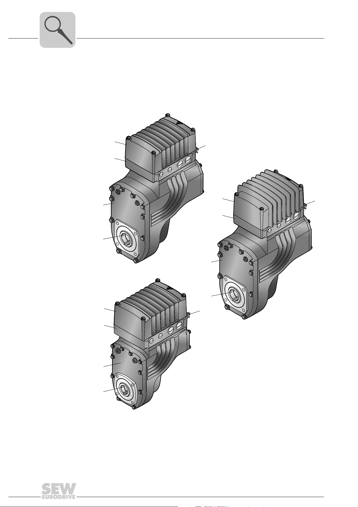
3.1 MOVIGEAR® drive unit
MOVIGEAR® drive units are made up of 3 core components: gear unit, motor and drive
electronics. These 3 core components are included in one cast aluminum housing (see
following figure).
MGF..4
[3]
[4]
[1]
[1]
[2]
MGF..2
[5]
[3]
[4]
[5]
MGF..4/ET
[1]
[2]
[5]
12
[2]
[3]
[4]
2363886987
[1] MOVIGEAR® electronics cover
[2] Connection ring for cable glands
[3] Gear unit cover
[4] Output shaft version (pictured here: hollow shaft with keyway)
[5] Grounding screws
Operating Instructions – MOVIGEAR® DSC-B
Page 13
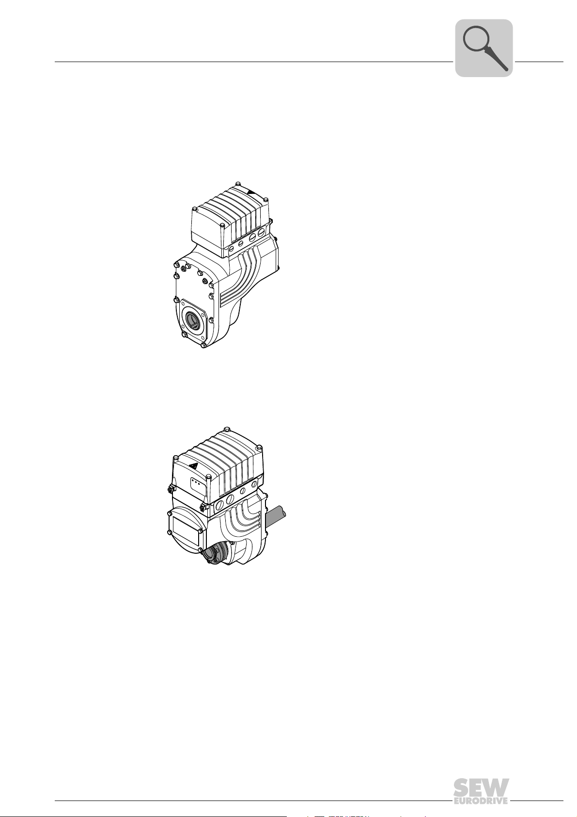
3.2 Shaft variants
MOVIGEAR® is available with the following shaft variants:
®
3.2.1 MOVIGEAR
with hollow shaft and keyway (MGFA..)
The following figure shows a MOVIGEAR
Unit Design
Shaft variants
®
unit with hollow shaft and keyway:
3
3.2.2 MOVIGEAR
2690820619
®
with TorqLOC® hollow-shaft mounting system (MGFT..)
The following figure shows a MOVIGEAR
system
2690822539
®
unit with TorqLOC® hollow shaft mounting
Operating Instructions – MOVIGEAR® DSC-B
13
Page 14
3
Unit Design
Housing mounting
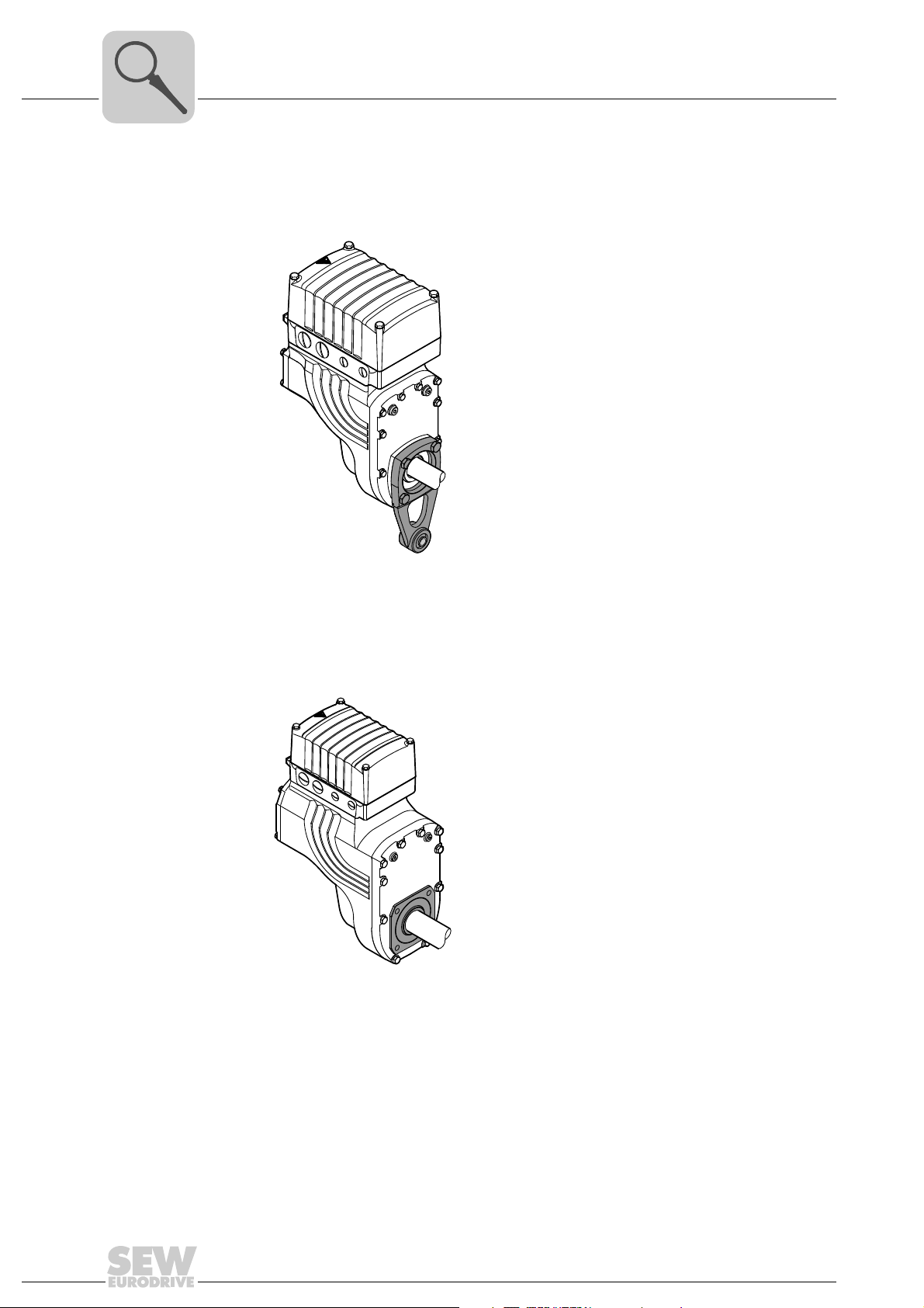
3.3 Housing mounting
3.3.1 Torque arm (MGF.T)
The following figure shows the torque arm for MGF.T:
3.3.2 Housing with threads (MGF.S)
The following figure shows the housing type with threads for mounting a torque arm.
This type does not include a centering shoulder, which means it is not suitable for direct
installation to the machine:
2690826379
2690824459
14
Operating Instructions – MOVIGEAR® DSC-B
Page 15
3.4 Position of the cable entry
The following cable entries are possible for MOVIGEAR®:
• Position X + 2
– X: 2 x M25 x 1.5 + 1 x M16 x 1.5 + 1 x M16 x 1.5
– 2: 2 x M25 x 1.5 + 1 x M16 x 1.5 + 1 x M16 x 1.5
• Position X + 2 + 3
– X: 2 x M25 x 1.5 + 1 x M16 x 1.5 + 1 x M16 x 1.5
– 2: 2 x M25 x 1.5 + 1 x M16 x 1.5 + 1 x M16 x 1.5
– 3: 2 x M25 x 1.5 + 2 x M16 x 1.5
• Position X + 3
– X: 2 x M25 x 1.5 + 1 x M16 x 1.5 + 1 x M16 x 1.5
– 3: 2 x M25 x 1.5 + 2 x M16 x 1.5
• Position 2 + 3
– 2: 2 x M25 x 1.5 + 1 x M16 x 1.5 + 1 x M16 x 1.5
Unit Design
Position of the cable entry
1)
1)
1)
1)
1)
1)
3
3.4.1 Overview
– 3: 2 x M25 x 1.5 + 2 x M16 x 1.5
The following figure shows the possible cable entries:
2
X
3
2
X
3
2
3
X
1) 1 x M16 x 1.5 reserved for pressure compensation fitting in connection with the package for wet areas
Operating Instructions – MOVIGEAR® DSC-B
2690896779
15
Page 16
3
76646 Bruchsal/Germany
Nm
°C
n
R
U
N
f
N
Nm
n
A
A
M
A
M
a pk
i
Made in Germany
IM
kg
cos
IP
r/min
Hz
V
13356887
MGFAT2-DSM-DSC-B/DSP
01.1233697403.0001.08
5,4...53,7
37,24
M1,M2,M5,M6 50...60
380...500
65
0,99
1,52
1/10
16.000
CLP HC 220 Synth.Öl/0,55l
-25 ... +40
[1]
3~ EN61800
TENV
M.L.
143
220
Unit Design
Sample nameplate and type designation of drive unit
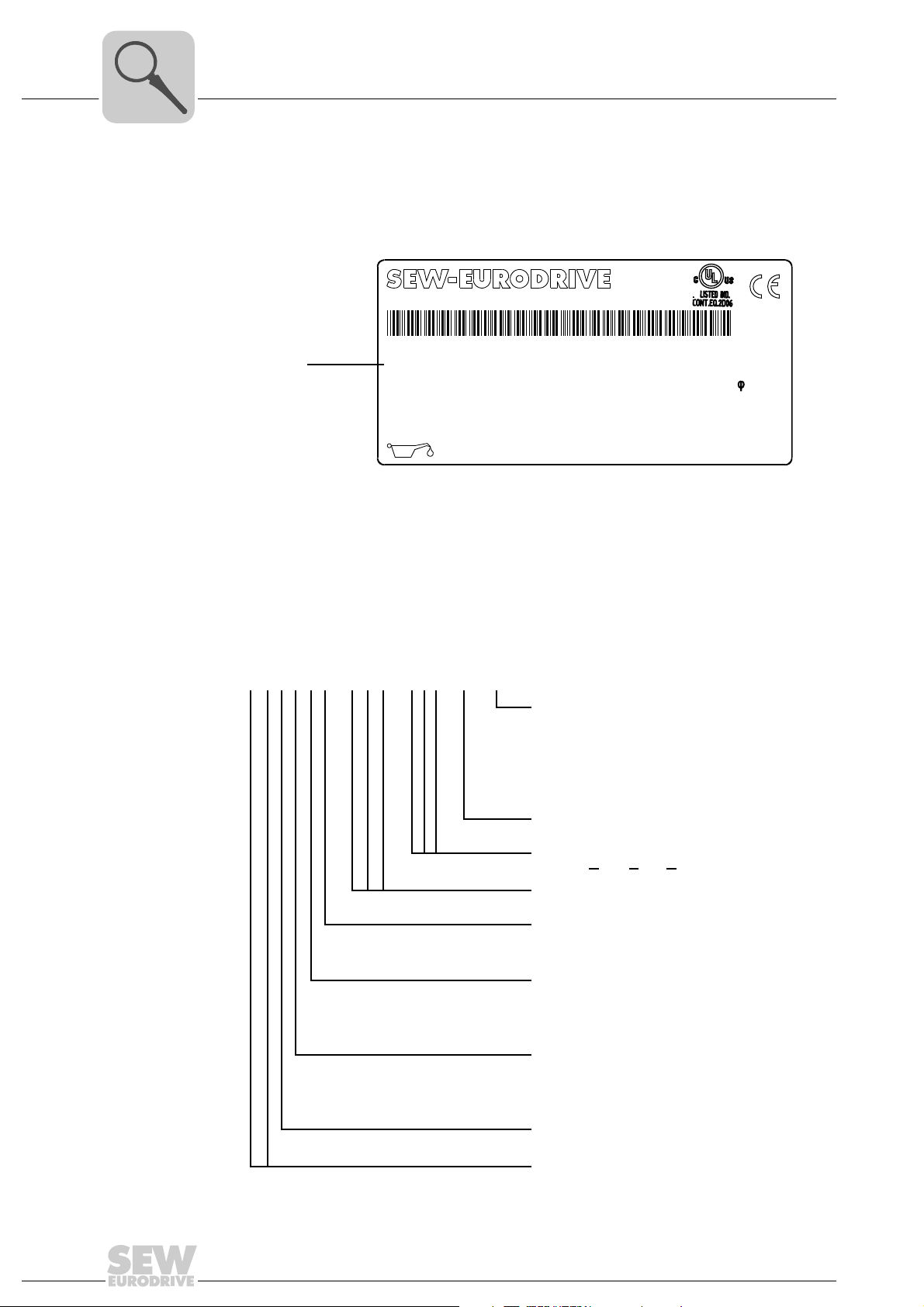
3.5 Sample nameplate and type designation of drive unit
3.5.1 Nameplate
The following figure gives an example of a MOVIGEAR
of the type designation, refer to chapter "Type designation".
[1] Unique serial number
®
nameplate. For the structure
2368165003
3.5.2 Type designation
16
Bar code:
The bar code on the nameplate (code 39) according to ISO/IEC 16388 represents the
unique serial number (with period as separator).
The following table shows the type designation of MOVIGEAR
®
:
MGFAS2–DSM–DSC–B / DSP
MOVIGEAR® option
DSP = Electrodynamic
deceleration function DynaStop
ECR = Extended control range
ET = Extended torque
IV = Plug connector
MOVIGEAR
MOVIGEAR
DSC = D
®
version
®
installation technology
irect SBus Communication
Motor type
Size
2 = Torque class 200 Nm
4 = Torque class 400 Nm
Housing mounting
T = Drive with torque arm
S = Housing with threads for
mounting a torque arm
Shaft variant
A = Shaft-mounted gear unit
(hollow shaft with keyway)
T = TorqLOC
®
hollow shaft mounting system
Gear unit type
F = Parallel-shaft helical gear unit
Product series
MG = MOVIGEAR
Operating Instructions – MOVIGEAR® DSC-B
®
®
Page 17
MOVIGEAR® electronics
OFF
ON
S1
OFF
ON
S1
[1]
[2]
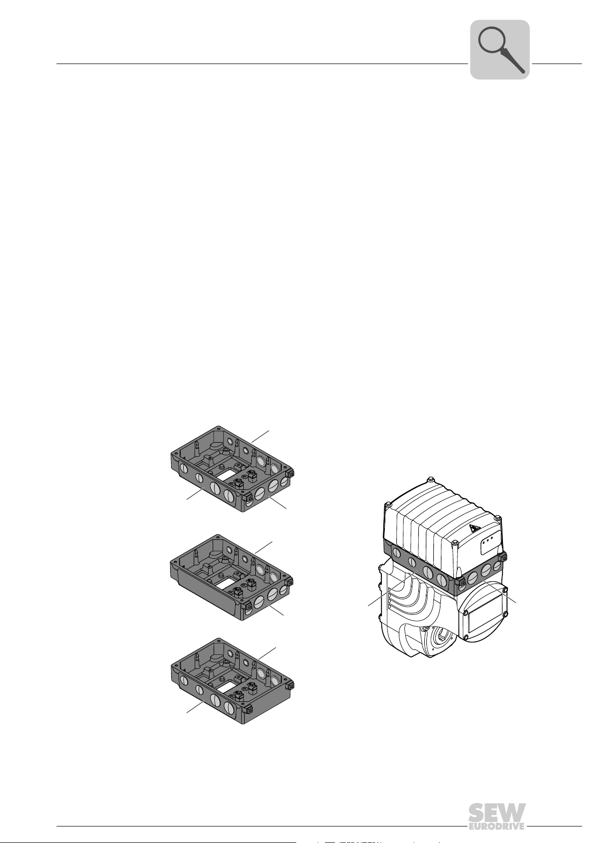
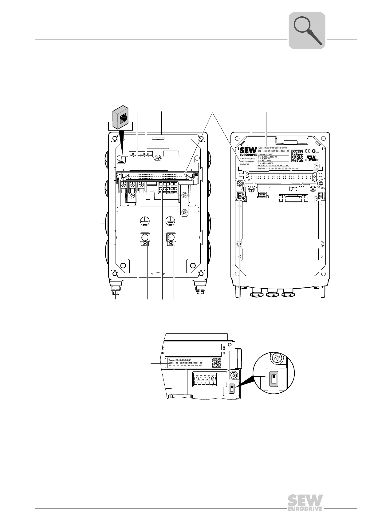
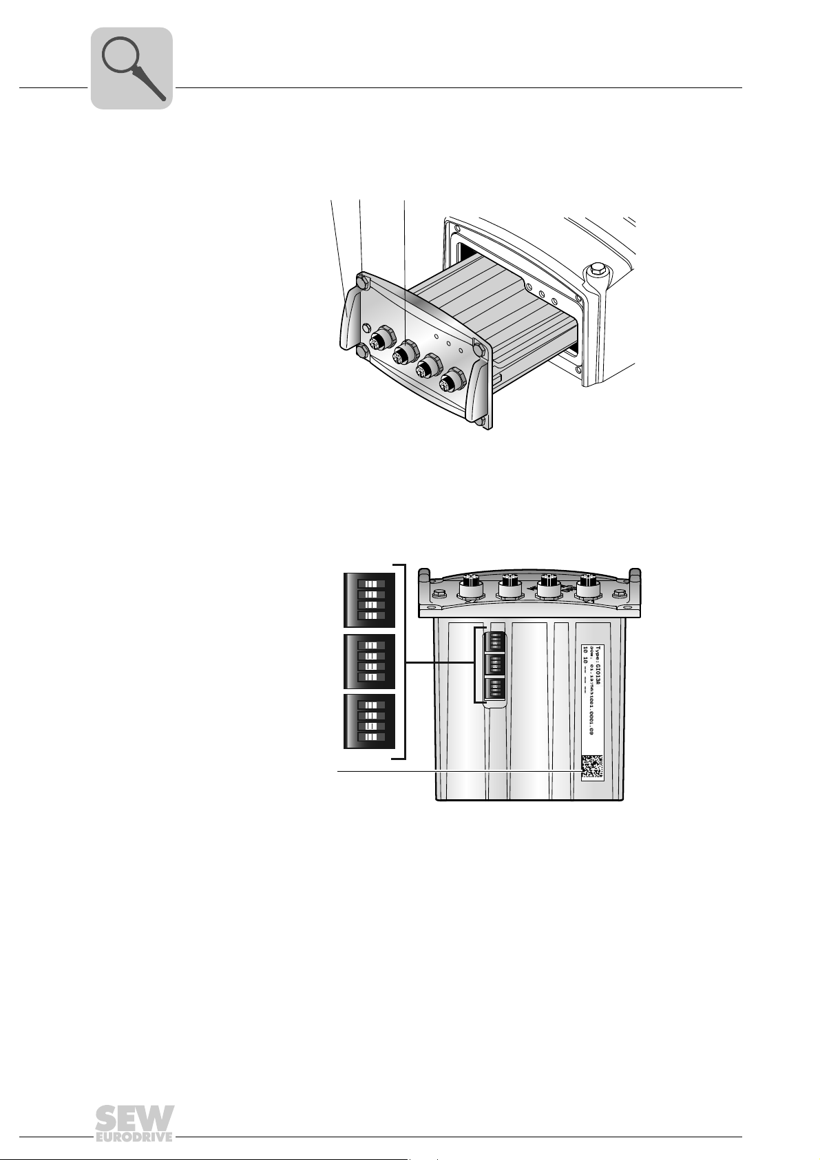
3.6 MOVIGEAR® electronics
3.6.1 MOVIGEAR® electronics cover (inside) and connection box
The following figure shows the connection box and the bottom side of the MOVIGEAR
electronics cover:
Unit Design
3
®
[1]
[2]
[3]
[4]
[5] [6] [7]
[9] [9][9]
[8]
[1] DIP switch S1 for bus termination, see following detailed view
[2] Nameplate of drive unit, see following detailed view
[3] SBus connection
[4] Connection ring
[5] Plug connector connection unit for MOVIGEAR
[6] MOVIGEAR
[7] Electronics cover nameplate
[8] Cable glands
[9] Screw for PE connection
[10] Supply system connection L1, L2, L3
[11] Electronics terminal strips
[12] DIP switches S2/1 – S2/4
[13] DIP switches S1/1 – S1/4
[9]
[10]
®
electronics cover
[11]
[8]
®
electronics cover
[12]
[13]
2389455499
2490703499
Operating Instructions – MOVIGEAR® DSC-B
17
Page 18
3
Unit Design
MOVIGEAR® electronics
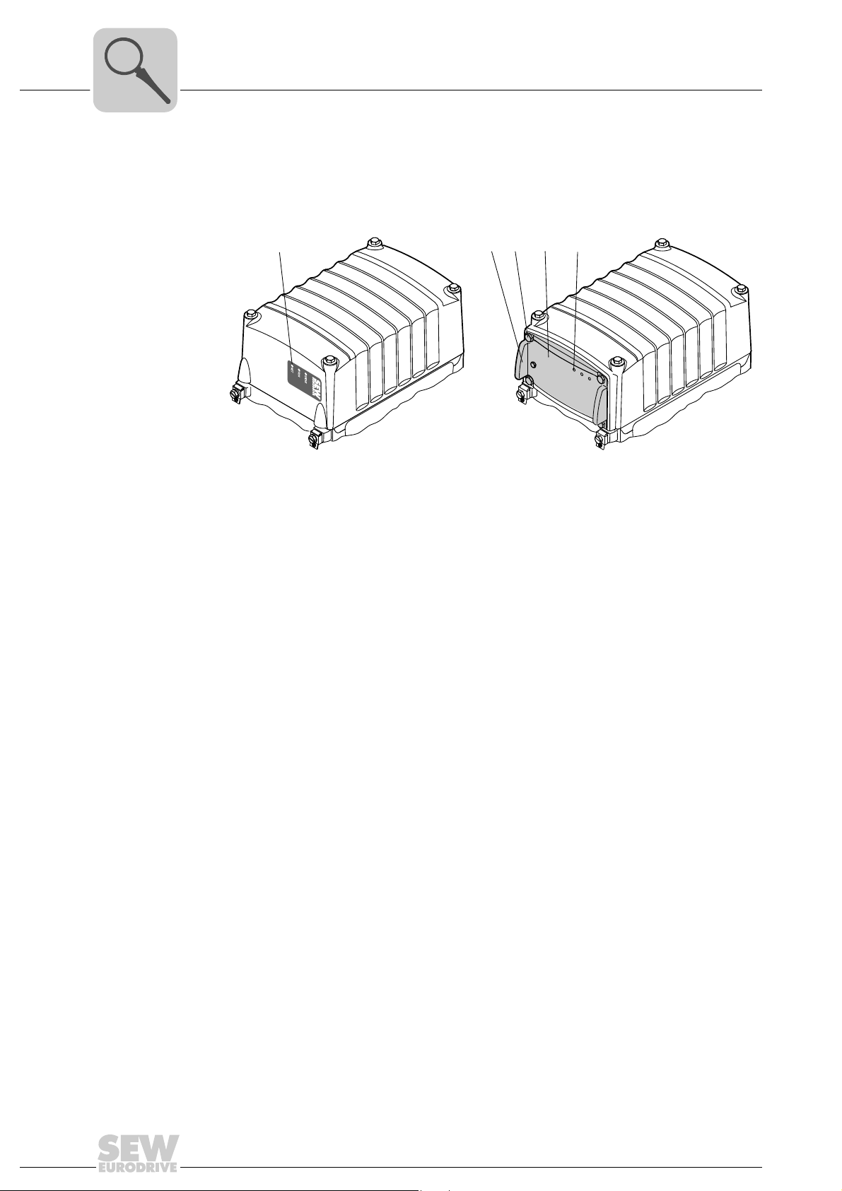
3.6.2 MOVIGEAR® electronics cover (outside)
The following figure shows possible types of the MOVIGEAR
MOVIGEAR® electronics cover
without application slot
[1]
[1]
MOVIGEAR
with application slot
and application cover
[2]
[3]
®
electronics cover:
®
electronics cover
[4]
NET
RUN
DRIVE
2367948939
[1] LED displays [1] Assembly/disassembly handle
[2] Retaining screws (4x)
[3] Application cover
[4] LED displays
18
Operating Instructions – MOVIGEAR® DSC-B
Page 19
3.7 Application options
DRIVE
RUN
NET
[3]
[1]
[2]
[1]
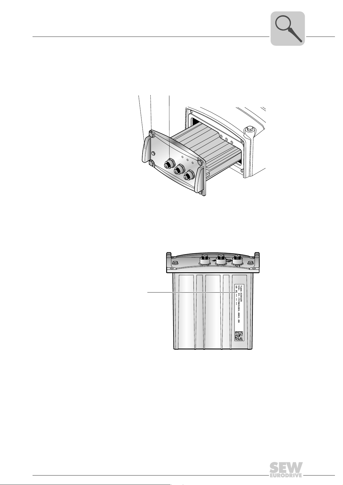
3.7.1 GIO12A application option
The following figure shows the GIO12A application option:
Unit Design
Application options
3
[1] Assembly/disassembly handle
[2] Retaining screws (4x)
[3] M12 plug connector for digital I/Os
The following figure shows the position of the GIO12A nameplate:
[1] Nameplate
2368100235
2701486347
Operating Instructions – MOVIGEAR® DSC-B
19
Page 20
3
DRIVE
RUN
NET
[3]
[1]
[2]
Unit Design
Application options
3.7.2 GIO13A application option
The following figure shows the GIO13A application option:
2585028875
[1] Assembly/disassembly handle
[2] Retaining screws (4x)
[3] M12 plug connector for digital/analog I/Os
The following figure shows the DIP switches S1 to S3 of the GIO13A application option:
ON
1234
S1
ON
1234
ON
1234
ON
1234
S2
ON
1234
ON
1234
S3
[1]
2736188299
[1] Nameplate
20
Operating Instructions – MOVIGEAR® DSC-B
Page 21
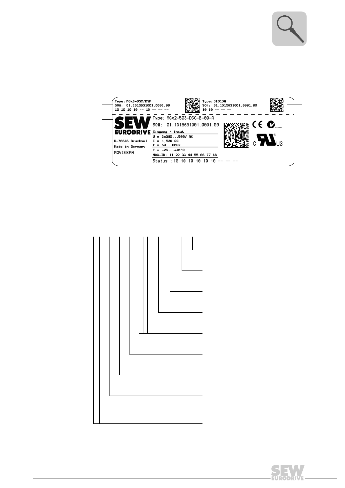
Unit Design
[1]
[3]
[2]
Sample nameplate and type designation for electronics
3.8 Sample nameplate and type designation for electronics
3.8.1 Nameplate
The following figure gives an example of a MOVIGEAR
of the type designation, refer to chapter "Type designation".
[1] Nameplate of connection unit
[2] Nameplate of application option
[3] Electronics cover nameplate
®
nameplate. For the structure
2585099787
3
3.8.2 Type designation of electronics cover
The following table shows the type designation of the electronics cover:
M G x 4 – 5 0 3 – DSC – B – 00 – A / ET
Electronics cover option
ET = Extended torque
Electronics cover variant
A = With application slot
Variant
00 = Standard
MOVIGEAR
Version
MOVIGEAR
DSC = D
Connection type
3 = 3-phase
Supply voltage
50 = AC 380 – 500 V
®
®
installation technology
irect SBus Communication
Operating Instructions – MOVIGEAR® DSC-B
Size
2 = Torque class 200 Nm
4 = Torque class 400 Nm
Product series
MG = MOVIGEAR
®
21
Page 22
3
Unit Design
Sample nameplate and type designation for electronics
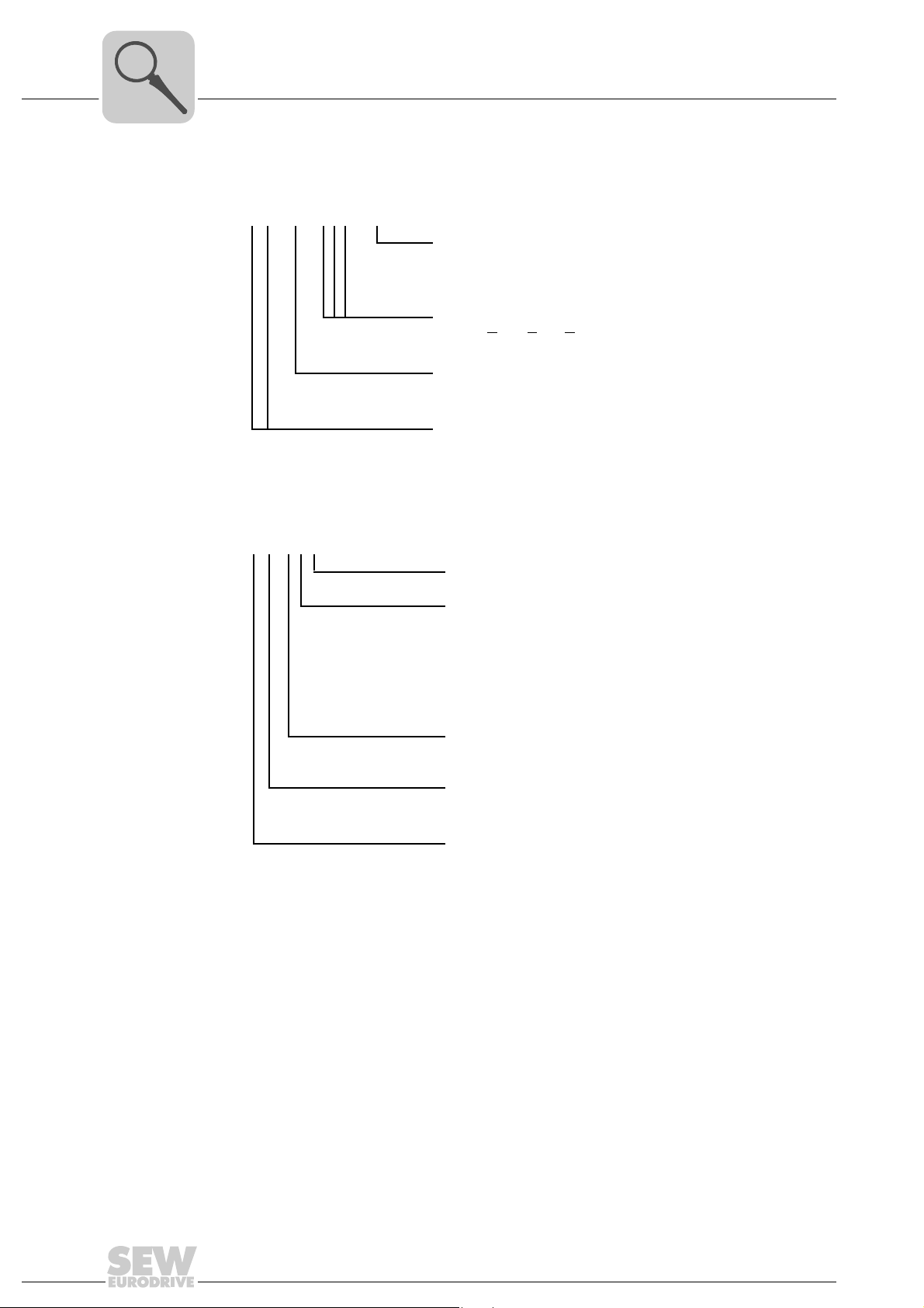
3.8.3 Type designation of connection unit
The following table shows the type designation of the connection unit:
M G x B – DSC / DSP
Connection unit option
DSP = Electrodynamic
deceleration function DynaStop
®
MOVIGEAR
DSC = D
installation technology
irect SBus Communication
®
3.8.4 Type designation of application options
The following table shows the unit designation for the available application options:
G IO 1 2 A
MOVIGEAR
Version
Product series
MG = MOVIGEAR
Version
Variant
2 = 4 digital inputs + 2 digital outputs
3 = 4 digital inputs
(2 inputs can be used as primary frequency input)
+ 1 digital output
+ 1 analog input
+ 1 analog output
Version
Functionality
IO = Digital inputs/outputs
®
®
22
Product series
G = Option for MOVIGEAR
Operating Instructions – MOVIGEAR® DSC-B
®
Page 23
MOVIGEAR® with optional package for wet areas
[12]
[4]
[5]
[6]
[7]
[8]
B
B
A
A
[10] [9]
[11]
[2]
[1]
[3]
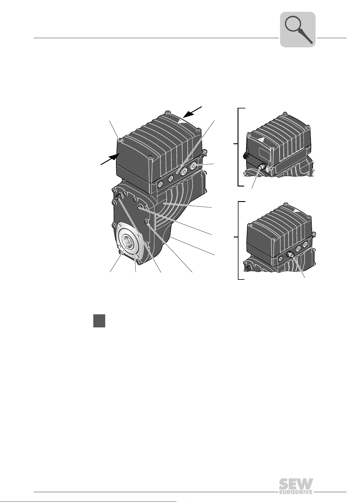
3.9 MOVIGEAR® with optional package for wet areas
3.9.1 Properties
The following figure shows the additional features of MOVIGEAR
optional package for wet areas:
Unit Design
®
drive units with
3
2368838155
3.9.2 Legend
All illustrations regarding MOVIGEAR® drive units with optional package for wet areas are
displayed with a shading (= HP200 surface protection) in this publication
[1] Mounting screws for electronics cover made of stainless steel
[2] Connection ring only possible with cable outlet "at the bottom" or "on the side":
[3] Screw plugs made of stainless steel installed at the factory
[4] HP200 surface protection, see chapter "Technical data and dimension sheets"
[5] Oil screw plug made of stainless steel (hexagon)
[6] Additional cover opposite the output side
[7] Mounting screws for gear unit housing made of stainless steel
[8] Breather valve mounted and activated according to mounting position, see chapter
[9] FKM oil seal (Viton)
[10] Output shaft made of stainless steel (can be deselected)
[11] Pre-installed pressure compensation fitting (M16) with mounting positions M5, M6
[12] Pre-installed pressure compensation fitting (M16) with mounting position M1, M2, M4, M4
– In connection with mounting position M1 and M2: 2 + 3, 2 + X, X + 3, 2 + X + 3
– In connection with mounting position M4: 2 + X
– In connection with mounting position M5: X + 3
– In connection with mounting position M6: 2 + 3
"Technical data and dimension sheets"
Optional plug connectors (see chapter "Electrical installation") are available in connection
with the package for wet areas.
Operating Instructions – MOVIGEAR® DSC-B
23
Page 24
4
Mechanical Installation
Installation notes
4 Mechanical Installation
4.1 Installation notes
INFORMATION
Comply with the safety notes during installation.
Improper installation/disassembly of MOVIGEAR® and mount-on components.
Risk of injury.
• Note the information about installation and disassembly in this chapter.
• Before releasing shaft connections, make sure that there are no active torsional
moments present (tensions within the system).
CAUTION
DANGER
Risk of crushing if the drive starts up unintentionally and danger of electrical voltage.
Dangerous voltages may still be present for up to 10 minutes after disconnection from
the power supply.
Severe or fatal injuries.
• Completely disconnect the MOVIGEAR
provide for suitable external measures to secure against unintentional
reconnection!
• Secure the output shaft against rotation.
• Then wait for at least 10 minutes
4.2 Required tools and resources
• Set of wrenches
• Torque wrench
• Mounting device
• Compensation elements (shims and spacing rings), if necessary
• Mounting materials for output components
• Lubricant (e.g. NOCO
®
fluid)
®
drive unit from the power supply and
• Standard parts are not included in the delivery
4.2.1 Installation tolerances for shaft ends
Diameter tolerance in accordance with DIN 748:
• ISO H7 for hollow shafts
24
Operating Instructions – MOVIGEAR® DSC-B
Page 25

4.3 Installation prerequisites
Check that the following conditions have been met:
• The entries on the nameplate of the MOVIGEAR
system.
• The drive is undamaged (no damage caused by transportation or storage)
• Ambient temperature according to the operating instructions, nameplate and lubricant table in chapter "Technical data and dimension sheets / Lubricants".
• The drive must not be assembled in the following ambient conditions:
– Potentially-explosive atmosphere
– Oils
–Acids
– Gases
– Vapors
– Radiation
Mechanical Installation
Installation prerequisites
®
unit match the voltage supply
4
• For special designs: The drive is designed in accordance with the actual ambient
conditions.
• You must clean the output shafts and flange surfaces thoroughly to ensure they are
free of anti-corrosion agents, contamination or the like. Use conventional solvents.
Do not expose the sealing lips of the oil seals to the solvent – damage to the material.
• When the drive is installed in abrasive ambient conditions, protect the output end oil
seals against wear.
Operating Instructions – MOVIGEAR® DSC-B
25
Page 26
4
100
Mechanical Installation
Installing MOVIGEAR
4.4 Installing MOVIGEAR®
• Clean the output shafts thoroughly to ensure they are free of anti-corrosion agents
• Carefully align the MOVIGEAR
• Do not butt or hammer the shaft end.
• Ensure that cooling air supply is unobstructed and that air discharged by other units
• Use suitable cable glands for the supply leads (use reducing adapters if necessary).
• Seal the cable entry well.
• Clean the sealing faces of the MOVIGEAR
• Restore the corrosion protection if necessary.
• Check the validity of the degree of protection using the information in the operating
®
(use a commercially available solvent). Do not expose the bearings and sealing rings
to the solvent – damage to the material!
®
unit and the driven machine to avoid placing any
unacceptable strain on the motor shafts (observe permissible overhung loads).
does not influence cooling.
®
cover well before reassembling the unit.
instructions and the data on the nameplate.
• When changing the mounting position: Adjust position of breather valve.
Observe chapter "Technical data and dimension sheets / Mounting positions".
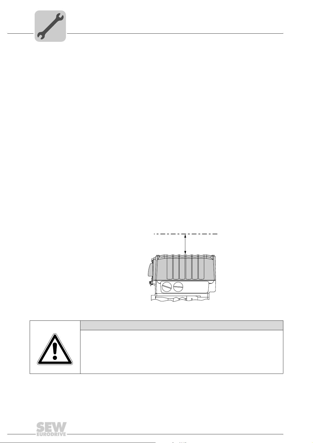
4.4.1 Minimum installation clearance of electronics cover
Note the minimum installation clearance (see following figure) required to remove the
MOVIGEAR
"Technical data and dimension sheets".
®
electronics cover. For detailed dimension drawings, see chapter
NOTICE
The degree of protection specified in the technical data only applies if the MOVIGEAR
electronics cover is properly installed.
When the MOVIGEAR
be damaged by humidity, dust or foreign particles.
• Protect the MOVIGEAR
box.
®
electronics cover is removed from the connection box, it might
®
electronics cover when it is removed from the connection
2350097419
®
26
Operating Instructions – MOVIGEAR® DSC-B
Page 27
Mechanical Installation
200
Installing MOVIGEAR
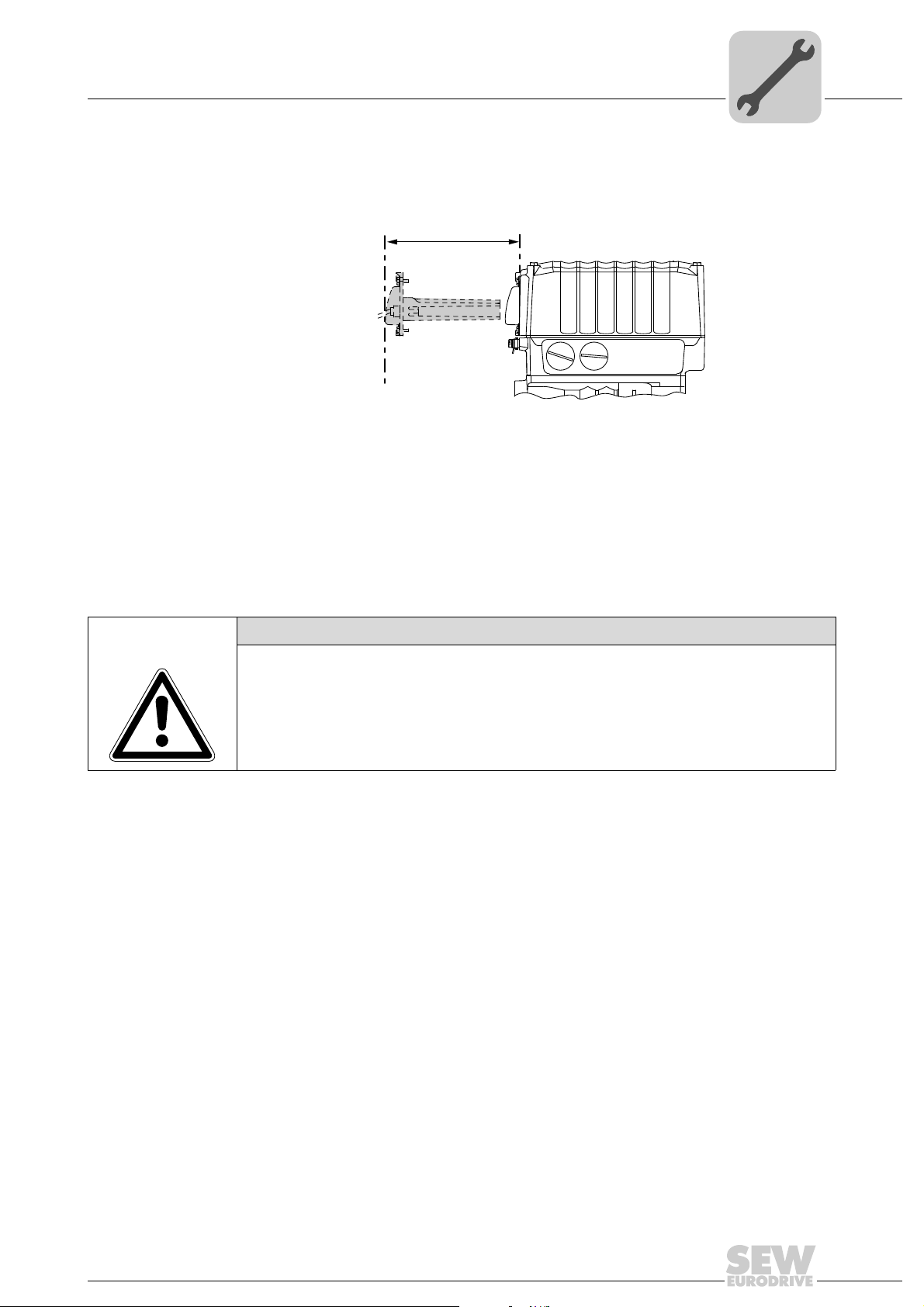
4.4.2 Minimum installation clearance of application options
Note the minimum installation clearance (see following figure) required to install and
remove the application options.
4.4.3 Installation in damp locations or in the open
Drives are supplied in corrosion-resistant versions for use in damp areas or in the open.
Repair any damage to the paint work if necessary.
For variants with HP200 surface treatment, observe the notes in chapter "MOVIGEAR
with optional package for wet areas".
®
2350130571
4
®
4.4.4 Painting MOVIGEAR
NOTICE
Breather valves and oil seals may be damaged during painting or re-painting.
Potential damage to property.
• The surface of the drive must be clean and free from grease.
• Thoroughly cover the breather valves and the sealing lip of the oil seals with strips
prior to the painting process.
• Remove the strips after the process.
®
Operating Instructions – MOVIGEAR® DSC-B
27
Page 28
4
Mechanical Installation
Installing MOVIGEAR
4.4.5 MOVIGEAR® gear unit venting
®
MOVIGEAR
with
installed breather
valve
SEW-EURODRIVE delivers all MOVIGEAR® drive units ordered for a specific mounting
position with a breather valve that is activated and installed according to the mounting
position.
MOVIGEAR
with the activated breather valve installed corresponding to the respective mounting
position.
®
®
drive units with optional "package for wet areas" are generally delivered
®
MOVIGEAR
with
separately
included breather
valve
Activating the
breather valve
MOVIGEAR
®
drive units ordered for a universal mounting position are delivered by
SEW-EURODRIVE with a separately included breather valve.
In this case, the breather valve is delivered in the hollow shaft of the drive unit. Before
startup, you must replace the highest oil screw plug with the provided breather valve.
After installing the breather valve, you must activate it as follows. For designs with the
breather valve screwed in: Check whether the breather valve is activated. If not, you
have to remove the transport fixture of the breather valve prior before you start up the
drive unit!
1. Breather valve with transport fixture
2350149003
2. Remove transport fixture
28
2350216203
3. Activated breather valve
2350269835
Operating Instructions – MOVIGEAR® DSC-B
Page 29
4.5 Application options
DRIVE
RUN
NET
WARNING
The surface temperatures of the MOVIGEAR® and the application options can be very
high during operation.
Danger of burns.
• Do not touch the MOVIGEAR
down sufficiently.
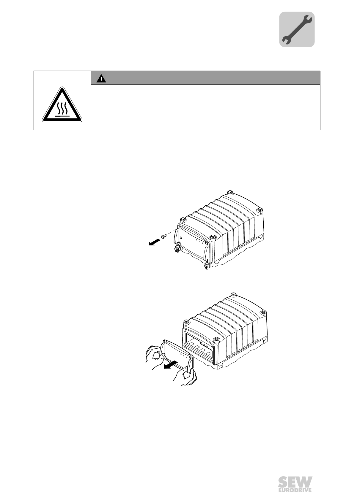
4.5.1 Removing the application cover
MOVIGEAR
application cover as standard.
You have to remove the application cover in order to install an application option:
1. Loosen the 4 retaining screws.
®
drives with application slot in the electronics cover are delivered with an
Mechanical Installation
Application options
®
drive and application options until they have cooled
4
4 x
2. Remove the application cover.
NET
RUN
DRIVE
2350325003
2350345355
Operating Instructions – MOVIGEAR® DSC-B
29
Page 30
4
Mechanical Installation
Application options
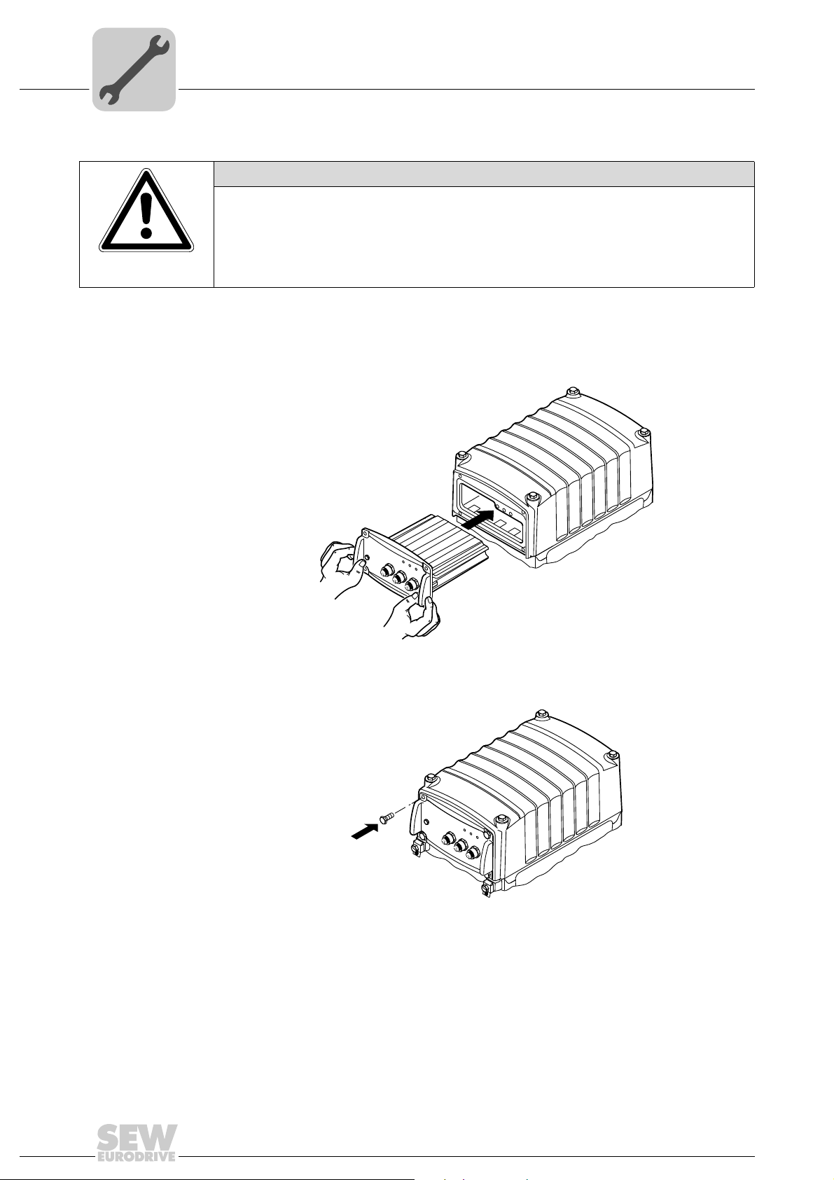
4.5.2 Installing application options
NOTICE
The degree of protection specified in the technical data only applies if the GIO13A
application option is properly installed.
In a disassembled state, the option can be damaged by moisture, dust, or foreign
objects entering through the openings for the DIP switches.
• Protect the GIO13A application option in a disassembled state.
1. You have to remove the application cover or, depending on the design, the paint
2. Insert the option into the application slot.
protector in order to install an application option:
NET
NET
RUN
DRIVE
2350364555
3. Secure the option with the 4 retaining screws. The permitted tightening torque for the
retaining screws is 1.2 - 1.4 Nm.
4 x
NET
RUN
DRIVE
2350383755
30
Operating Instructions – MOVIGEAR® DSC-B
Page 31

Shaft-mounted gear unit with keyway
N
O
C
O
F
L
U
I
NO
C
O
F
L
U
I
4.6 Shaft-mounted gear unit with keyway
INFORMATION
Observe the design notes in chapter "Technical data and dimension sheets" for the
customer shaft design.
4.6.1 Assembly instructions
1. Apply NOCO
®
fluid
Mechanical Installation
4
2. Distribute NOCO
®
fluid carefully
2348641291
2348643211
Operating Instructions – MOVIGEAR® DSC-B
31
Page 32

4
[1]
[2]
[3]
[4]
A
[6]
[1]
[2]
[3]
[4]
B
[6]
Mechanical Installation
Shaft-mounted gear unit with keyway
3. Insert the shaft and secure it axially (installation is made easier by using a mounting
device).
3A: Installation with standard scope of delivery
2348639371
[1] Short retaining bolt (standard delivery scope)
[2] Lock washer
[3] Washer
[4] Retaining ring
[6] Customer shaft
3B: Installation with the SEW-EURODRIVE assembly/disassembly kit. Observe
chapter "Technical data and dimension sheets/ Design notes for gear units
with hollow shaft and key".
Customer shaft with contact shoulder
2348637451
[1] Retaining screw
[2] Lock washer
[3] Washer
[4] Retaining ring
[6] Customer shaft with contact shoulder
32
Operating Instructions – MOVIGEAR® DSC-B
Page 33

Mechanical Installation
Shaft-mounted gear unit with keyway
3C: Installation with the SEW-EURODRIVE assembly/disassembly kit: Observe
chapter "Technical data and dimension sheets/ Design notes for gear units
with hollow shaft and key".
Customer shaft without contact shoulder
C
[1]
[2]
[3]
[4]
[5]
[6]
2348213131
4
[1] Retaining screw
[2] Lock washer
[3] Washer
[4] Retaining ring
[5] Spacer tube
[6] Customer shaft without contact shoulder
4. Tighten the retaining bolt to the appropriate torque (see table).
2348211211
Drive Screw Tightening torque
[Nm]
MGFA.2 M10 20
MGFA.4 M16 40
INFORMATION
To avoid contact corrosion, SEW-EURODRIVE recommends that the customer shaft
should additionally be lathed down between the 2 contact surfaces.
Operating Instructions – MOVIGEAR® DSC-B
33
Page 34

4
[1]
[2]
[3]
[4]
[5]
[6]
4.6.2 Disassembly notes
Mechanical Installation
Shaft-mounted gear unit with keyway
The following description only applies when the drive is disassembled using the SEWEURODRIVE assembly/disassembly kit (see previous description, points 3B or 3C).
INFORMATION
For information on the SEW-EURODRIVE assembly/disassembly kit, see chapter
"Technical data and dimension sheets / Design notes".
1. Loosen the retaining screw [1].
2. Remove parts [2] to [4] and, if applicable, the distance piece [5].
2348647051
[1] Retaining screw
[2] Lock washer
[3] Washer
[4] Retaining ring
[5] Spacer tube
[6] Customer shaft
3. Insert the forcing disk [8] and the fixed nut [7] from the SEW-EURODRIVE installation/removal kit between the customer shaft [6] and the retaining ring [4].
4. Re-install the retaining ring [4].
5. Screw the retaining screw [1] back in. Now you can force the drive off the shaft by
tightening the bolt.
[1]
[4]
[7]
[8]
[6]
34
2348645131
[1] Retaining screw
[4] Retaining ring
[6] Customer shaft
[7] Fixed nut
[8] Forcing disk
Operating Instructions – MOVIGEAR® DSC-B
Page 35

Shaft-mounted gear unit with TorqLOC
N
O
C
O
F
L
U
I
D
®
4.7 Shaft-mounted gear unit with TorqLOC® (customer shaft without contact shoulder)
1. Clean the inside of the hollow shaft and the customer shaft carefully. Ensure that all
traces of grease or oil are removed. Install the stop ring and the bushing on the
customer shaft.
Mechanical Installation
®
4
2. Mount the torque arm to MOVIGEAR
®
3. Apply NOCO
fluid to the bushing and distribute it carefully.
®
; observe chapter "Torque arm".
2348651531
2348976011
Operating Instructions – MOVIGEAR® DSC-B
2348653451
35
Page 36

4
Mechanical Installation
Shaft-mounted gear unit with TorqLOC®
4. Push the gear unit onto the customer shaft.
2348983691
5. Preassemble the torque arm (do not tighten the screws).
36
2348979851
6. Push the busing onto the gear unit up to the stop.
2348972171
Operating Instructions – MOVIGEAR® DSC-B
Page 37

Mechanical Installation
Shaft-mounted gear unit with TorqLOC
7. Secure the bushing with the split ring. Tighten the split ring on the bushing using the
appropriate torque as specified in the following table.
®
2348974091
4
Typ e Tightening torque [Nm]
Standard design Stainless steel
MGFT.2 18 7.5
MGFT.4 18 7.5
8. Slide the shrink disk onto the hollow shaft. Ensure that all bolts have been loosened.
2348657291
Operating Instructions – MOVIGEAR® DSC-B
37
Page 38

4
NO
C
O
F
L
UI
D
®
Mechanical Installation
Shaft-mounted gear unit with TorqLOC®
9. Push the counter bushing onto the customer shaft and into the hollow shaft all the
way to the seat.
2348981771
10.Tap lightly on the collar of the counter bushing to ensure that the bushing is fitted
securely in the hollow shaft.
2348970251
11.Manually tighten the screws of the shrink disk and ensure that the end rings of the
shrink disk are parallel.
2348655371
38
Operating Instructions – MOVIGEAR® DSC-B
Page 39

Mechanical Installation
> 0 mm
> 0 mm
Shaft-mounted gear unit with TorqLOC
12.Tighten the locking bolts by working round several times from one bolt to the next
(not in diametrically opposite sequence). See the table for tightening torques.
®
NOTICE
After installation, the remaining gap between the outer rings of the shrink disks must be
> 0 mm.
4
16
5
Typ e Tightening torque [Nm]
Standard design Stainless steel
MGFT.2 10 6.8
MGFT.4 12 6.8
2
5
34
> 0 mm
13
6
42
2348659211
13.The distance between the counter bushing and the hollow shaft end must match the
values in the following figure:
Operating Instructions – MOVIGEAR® DSC-B
2348661131
39
Page 40

4
Mechanical Installation
Shaft-mounted gear unit with TorqLOC®
14.Tighten the torque arm; observe chapter "Torque arm".
2348977931
4.8 Shaft-mounted gear unit with TorqLOC® (customer shaft with contact shoulder)
1. Clean the inside of the hollow shaft and the customer shaft carefully. Ensure that all
traces of grease or oil are removed.
2348994315
40
Operating Instructions – MOVIGEAR® DSC-B
Page 41

Mechanical Installation
0 mm
N
O
C
O
FL
UI
D
®
Shaft-mounted gear unit with TorqLOC
2. Slide the bushing onto the customer shaft.
®
3. Apply NOCO
fluid to the bushing and distribute it carefully.
®
2349377035
4
4. Push the gear unit onto the customer shaft.
2349367435
2348992395
Operating Instructions – MOVIGEAR® DSC-B
41
Page 42

4
NO
C
O
FL
UID
®
Mechanical Installation
Shaft-mounted gear unit with TorqLOC®
5. Slide the shrink disk onto the hollow shaft. Ensure that all screws have been
loosened.
2349371275
6. Push the counter bushing onto the customer shaft and into the hollow shaft all the
way to the seat.
2348990475
7. Tap lightly on the flange of the counter bushing to ensure that the socket is fitted
securely in the hollow shaft.
2349375115
42
Operating Instructions – MOVIGEAR® DSC-B
Page 43

Mechanical Installation
Shaft-mounted gear unit with TorqLOC
8. Manually tighten the screws of the shrink disk and ensure that the end rings of the
shrink disk are parallel.
9. Tighten the locking screws by working round several times from one screw to the
next (not in diametrically opposite sequence). See the table for tightening torques.
®
2349369355
4
NOTICE
After installation, the remaining gap between the outer rings of the shrink disks must be
> 0 mm.
16
5
Typ e Tightening torque [Nm]
Standard design Stainless steel
MGFT.2 10 6.8
MGFT.4 12 6.8
2
5
34
> 0 mm
13
6
42
2349373195
Operating Instructions – MOVIGEAR® DSC-B
43
Page 44

4
> 0 mm
> 0 mm
Mechanical Installation
Shaft-mounted gear unit with TorqLOC®
10.The distance between the counter bushing and the hollow shaft end must match the
values in the following figure:
2348661131
11.Preassemble the torque arm (do not tighten the screws).
44
2352754955
12.Tighten the torque arm; observe chapter "Torque arm".
2352757259
Operating Instructions – MOVIGEAR® DSC-B
Page 45

4.9 Installing the protective cover
15°
NOTICE
During operation, output components are in fast motion.
Risk of jamming and crushing.
• Disconnect the drive from the power supply and safeguard it against accidental
startup before starting work and.
• Cover input and output components with a touch guard.
4.9.1 Installing the fixed cover
1. Place the cover offset by 15° counterclockwise
Mechanical Installation
Installing the protective cover
4
2. Turn the cover clockwise until it locks in position.
3. The following figure shows the installed cover:
2349379723
2349381643
Operating Instructions – MOVIGEAR® DSC-B
2349383563
45
Page 46

4
[1]
90°
[B]
[A]
Mechanical Installation
Torque arm
4.9.2 Installation without cover
4.10 Torque arm
In certain individual cases (e.g. through-shaft), you cannot install the cover. In these
cases, the cover is not necessary if the system or unit manufacturer provides
corresponding components to guarantee for the compliance with the required degree of
protection.
If this results in additional maintenance, you have to describe this in the operating
instructions for the system or component.
NOTICE
Inappropriate installation might damage the MOVIGEAR® drive unit.
Possible damage to property.
• Do not place torque arms under strain during installation.
• Always use bolts of quality 8.8 to fasten torque arms.
4.10.1 MGF.T2 and MGF.T4 torque arm
Installation options The following figure shows the MGF.T2 and MGF.T4 torque arm:
[1] Apply bearings to both ends of the bushing
2350520459
46
Tightening
torques
The following table shows the required tightening torques:
Drive Screw A Screw B
Size Tightening torque
[Nm]
MGF.T2 M10 48 Nm M10 20 Nm
MGF.T4 M12 70 Nm M10 20 Nm
Operating Instructions – MOVIGEAR® DSC-B
Size Tightening torque
[Nm]
Page 47

Mechanical Installation
Tightening torques
4.11 Tightening torques
Warning
The surface temperatures of the MOVIGEAR® and the application options can be very
high during operation.
Danger of burns.
• Do not touch the MOVIGEAR
down sufficiently.
4.11.1 Blanking plugs
Tighten the blanking plugs included in the delivery
Example The following figure shows an example. The number and position of the cable entries
depends on the ordered variant.
®
drive and application options until they have cooled
with 2.5 Nm:
4
Operating Instructions – MOVIGEAR® DSC-B
2350608651
47
Page 48

4
Mechanical Installation
Tightening torques
4.11.2 Cable glands
Tightening
torques
Tighten the EMC cable glands optionally included in the delivery
tightening torques:
Screw fitting Part number Size Tightening torque
EMC cable glands (nickel-plated
brass)
EMC cable glands (stainless
steel)
1820 478 3 M16 x 1.5 3.5 Nm to 4.5 Nm
1820 480 5 M25 x 1.5 6.0 Nm to 7.5 Nm
1821 636 6 M16 x 1.5 3.5 Nm to 4.5 Nm
1821 638 2 M25 x 1.5 6.0 Nm to 7.5 Nm
with the following
The cable retention in the cable gland must withstand the following removal force of the
cable from the cable gland:
• Cable with outer diameter > 10 mm: ≥ 160 N
• Cable with outer diameter < 10 mm: = 100 N
Example The following figure shows an example. The number and position of the cable entries
depends on the ordered variant.
48
2350588171
Operating Instructions – MOVIGEAR® DSC-B
Page 49

4.11.3 MOVIGEAR® electronics cover
1
2
4
3
4
2
3
1
Tighten the screws on the MOVIGEAR
diagonally across.
Mechanical Installation
Tightening torques
®
electronics cover using 6.0 Nm working
4
2350592011
Operating Instructions – MOVIGEAR® DSC-B
49
Page 50

4
Mechanical Installation
MOVIGEAR® with optional package for wet areas
4.12 MOVIGEAR® with optional package for wet areas
INFORMATION
SEW-EURODRIVE guarantees that the HP200 special surface is free from faults when
delivered. Report any transportation damage immediately.
Although the housing surfaces have a high impact resistance, they are to be handled
with care. The corrosion protection can be affected by damage to the surface as a
result from improper handling during transport, installation, operation, cleaning, etc.
SEW-EURODRIVE is not liable for such damage.
4.12.1 Installation notes
Observe the following additional notes when installing MOVIGEAR
optional package for applications in wet areas:
• Make sure to prevent moisture an dirt from entering the unit during the installation.
• After electrical installation, make sure that the sealing and sealing surfaces are clean
during assembly.
®
drive units with
• Check the state of the gasket during maintenance. If damaged: Consult SEWEURODRIVE.
• Make sure to install the cables with a drip loop.
• Only use the metal cable glands/screw plugs provided or offered by SEWEURODRIVE, see chapter "Technical data and dimension sheets".
• You must seal unused cable bushings and plug connectors with suitable screw plugs,
see chapter "Technical data and dimension sheets".
Example The following figure is an example of cable routing with drip loop:
50
2350617739
Operating Instructions – MOVIGEAR® DSC-B
Page 51

Mechanical Installation
MOVIGEAR® with optional package for wet areas
4
Mounting
positions
Mounting
positions
MOVIGEAR® drive units with optional package for wet areas are delivered with pressure
compensation and breather valve installed according to the mounting position.
This is why MOVIGEAR
mounting position specified in the order:
• Mounting position
–M1
–M2
– M3 (only after consultation with SEW-EURODRIVE)
–M4
–M5
–M6
• Cable entries
– Position 3 (not possible in conjunction with M4)
– Position 2 (not possible in conjunction with M5)
– Position X (not possible in conjunction with M6)
The following figure shows the position of MOVIGEAR
x
®
with optional package for wet areas must only be used in the
®
in mounting positions M1 to M6.
M1
2
3
2
3
x
M6
x
2
M5
3
2
M4
x
M3*
2
3
= Mounting position M3 only after consultation with SEW-EURODRIVE
*
x
M2
3
2
3
x
2351031563
Operating Instructions – MOVIGEAR® DSC-B
51
Page 52

4
Mechanical Installation
MOVIGEAR® with optional package for wet areas
4.12.2 Tightening torques regarding the optional package for applications in wet areas
WARNING
The surface temperature of the MOVIGEAR® can be very high during operation.
Danger of burns.
• Do not touch the MOVIGEAR
®
drive until it has cooled down sufficiently.
Blanking plugs Tighten the blanking plugs included in the delivery
Example The following figure shows an example. The number and position of the cable entries
depends on the ordered variant.
with 2.5 Nm.
52
2357713291
Operating Instructions – MOVIGEAR® DSC-B
Page 53

Mechanical Installation
1
2
4
3
4
2
3
1
MOVIGEAR® with optional package for wet areas
4
MOVIGEAR®
Proceed as follows when installing the MOVIGEAR® electronics cover:
electronics cover
Steps 1. Fix the MOVIGEAR
of 2 Nm
2351658251
®
cover in position on the connection box with a tightening torque
2. Tighten screws diagonally with 4 Nm.
3. Tighten screws with 6 Nm.
Operating Instructions – MOVIGEAR® DSC-B
53
Page 54

4
Mechanical Installation
MOVIGEAR® with optional package for wet areas
EMC cable glands Tighten the EMC cable glands optionally included in the delivery with the following
tightening torques:
Screw fitting Part number Size Tightening torque
EMC cable glands (nickel-plated
brass)
EMC cable glands (stainless
steel)
The cable retention in the cable gland must withstand the following removal force of the
cable from the cable gland:
• Cable with outer diameter > 10 mm: ≥ 160 N
• Cable with outer diameter < 10 mm: = 100 N
Example The following figure shows an example. The number and position of the cable entries
depends on the ordered variant.
1820 478 3 M16 x 1.5 3.5 Nm to 4.5 Nm
1820 480 5 M25 x 1.5 6.0 Nm to 7.5 Nm
1821 636 6 M16 x 1.5 3.5 Nm to 4.5 Nm
1821 638 2 M25 x 1.5 6.0 Nm to 7.5 Nm
54
2351663371
Operating Instructions – MOVIGEAR® DSC-B
Page 55

Electrical Installation
Installation planning considering EMC aspects
5 Electrical Installation
INFORMATION
Comply with the safety notes during installation.
5.1 Installation planning considering EMC aspects
5.1.1 Notes on arranging and routing installation components
Successful installation of decentralized drives depends on selecting the correct cables,
providing correct grounding and a functioning equipotential bonding.
You must always apply the relevant standards. Also observe the following points in
particular:
5.1.2 Equipotential bonding
5
• Regardless of the protective earth connection, it is essential that low-impedance, HFcapable equipotential bonding is provided (see also VDE 0113 or VDE 0100
part 540):
– Establish a connection over a wide surface area between the MOVIGEAR
unit and the mounting rail.
– To do so, use a ground strap (HF litz wire) to connect the MOVIGEAR
and the plant's grounding point.
• Do not use cable shields for equipotential bonding.
5.1.3 Cable routing and cable shielding
It is essential that you observe the detailed information in chapter "Cable routing and
cable shielding".
WARNING
®
drive
®
drive unit
2377213963
Faulty installation.
Severe or fatal injuries from electric shock.
• Installation must be carried out with great care.
• Note the connection examples in chapter "Installation instructions / Cable routing
and cable shielding".
INFORMATION
Additional information is available in the SEW-EURODRIVE publication "Drive
Engineering – Practical Implementation, EMC in Drive Engineering".
Operating Instructions – MOVIGEAR® DSC-B
55
Page 56

5
Electrical Installation
Installation instructions
5.2 Installation instructions
5.2.1 Connecting the supply system leads
• The rated voltage and rated frequency of MOVIGEAR
supply system data.
®
must correspond with the
• Cable cross section: according to input current I
"Technical data and dimension sheets").
• Install line fuses at the beginning of the supply system line behind the supply bus
junction. Select the fuse size according to the cable cross section.
• Use only copper cables with a minimum temperature range of 85 °C as the
connection cable.
• MOVIGEAR
star point (TN and TT systems).
®
is intended to be operated on voltage supply systems with grounded
at rated power (see chapter
supply
56
Operating Instructions – MOVIGEAR® DSC-B
Page 57

Electrical Installation
Installation instructions
5.2.2 Permitted cable cross section of the terminals
Supply system
terminals
Control terminals Observe the permitted cable cross sections for installation:
Observe the permitted cable cross sections for installation:
Supply system terminals
2
- 4.0 mm
Connection cross section
2
)
(mm
Connection cross section
(AWG)
Conductor end sleeves • For single assignment:
Control terminals
Connection cross section
2
)
(mm
Connection cross section
(AWG)
Stripping length 6 mm
Conductor end sleeves When using conductor end sleeves, the permitted cross section is
1.0 mm
AWG17 - AWG12
Only connect single-wire conductors or flexible conductors with
conductor end sleeve (DIN 46228 part 1, material E-CU) with or
without insulating shrouds
• For double assignment:
Only connect flexible conductors with conductor end sleeve
(DIN 46228 part 1, material E-CU) without insulating shrouds
• Permitted length of the conductor end sleeve: At least 8 mm
2
0.08 mm
AWG 28 - AWG 14
reduced by one unit (e.g. 2.5 mm
- 2.5 mm
2
2
2
to 1.5 mm2)
5
Communication
terminals
Observe the permitted cable cross sections for installation:
Communication terminals
Connection
cross section
2
(mm
)
Connection
cross section
(AWG)
Conductor end
sleeves
Single-wire
conductor
(bare wire)
Only connect single-wire conductors or flexible conductors with or without conductor end
sleeve (DIN 46228 part 1, material E-CU)
Flexible conductor
(bare litz wire)
2
0.5 mm
– 1.0 mm
AWG20 – AWG17 AWG20 – AWG18
Conductor with
conductor end
without insulating
shrouds
2
sleeve
Conductor with
conductor end
sleeve
with insulating
shroud
0.5 mm2 – 0.75 mm
2
Operating Instructions – MOVIGEAR® DSC-B
57
Page 58

5
5.2.3 Actuating the control terminal clamps
Electrical Installation
Installation instructions
Note the following information for actuating the control terminal clamps:
Control terminals (the following figure shows a schematic illustration)
3.
1.
2.
2378449419
58
Operating Instructions – MOVIGEAR® DSC-B
Page 59

5.2.4 Actuating the communication terminal clamps
Note the following information for actuating the communication terminal clamps:
Electrical Installation
Installation instructions
5
Connecting the conductor
without pushing the actuation button
2378468875 2378488843
Single-wire conductors and flexible conductors with
conductor end sleeves can be installed directly
(without tool) up to two cross section sizes below
the nominal cross section.
Connecting the conductor
after pressing the actuation button
1.
2.
You will need to press the actuation button on top to
open the clamping spring for installing untreated,
flexible conductors or those with a small cross
section that cannot be installed directly.
Removing the conductor,
after pressing the actuation button
1.
2.
Before removing the conductor, first press the actuation button on top.
2378520459
Operating Instructions – MOVIGEAR® DSC-B
59
Page 60

5
5.2.5 Line protection and earth-leakage circuit breakers
Electrical Installation
Installation instructions
• Install the fuses at the beginning of the supply system leads behind the supply bus
junction.
• SEW-EURODRIVE recommends that you do not use earth-leakage circuit breakers.
However, if an earth-leakage circuit breaker is stipulated for direct or indirect protection against contact, observe the following note in accordance with EN 61800-5-1:
WARNING
Wrong type of earth-leakage circuit breaker installed.
Severe or fatal injuries.
• MOVIGEAR
leakage circuit breaker is used for protection against direct or indirect contact, only
install a type B earth-leakage circuit breaker on the power supply end of the
MOVIGEAR
5.2.6 Line contactor
®
can cause direct current in the protective earth. When an earth-
®
unit.
Jog mode
• Use contactor switch contacts of utilization category AC-3 according to IEC 158 to
connect the supply system cable.
NOTICE
• Do not use the K11 input contactor for jog mode, but only for switching the inverter
on and off. Use control commands for jog mode.
• Observe a minimum switch-off time of 2 s for the supply system contactor K11.
60
Operating Instructions – MOVIGEAR® DSC-B
Page 61

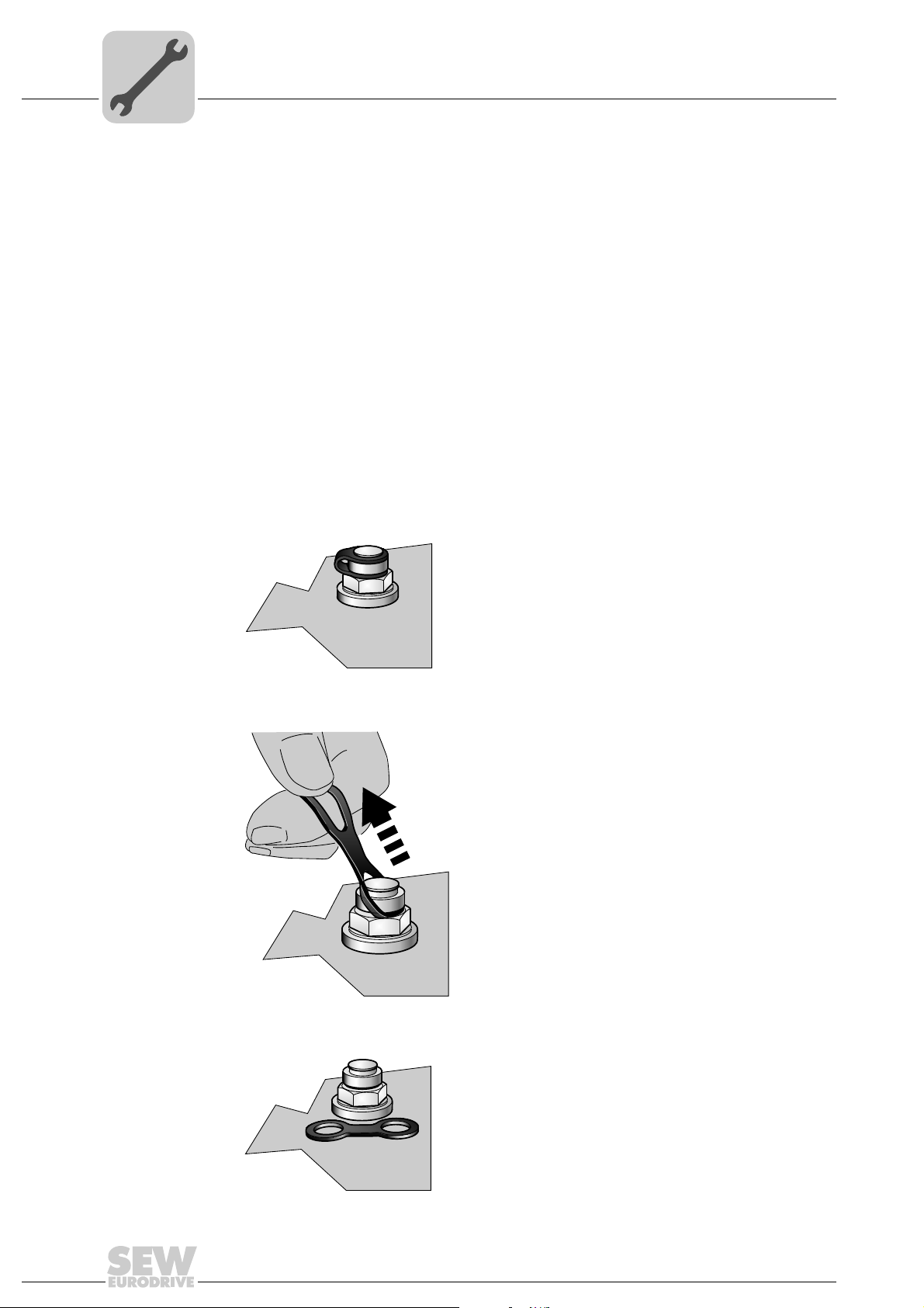
5.2.7 Notes on PE connection of MOVIGEAR®
[1]
M5
2.5 mm²
M5
DANGER
Incorrect connection of PE.
Death, severe injuries or damage to property from electric shock.
• The permitted tightening torque for the screw fitting is 2.0 to 2.4 Nm (18...21 lb.in).
• Observe the following notes regarding the PE connection:
Electrical Installation
Installation instructions
5
Prohibited assembly sequence Recommendation:
Assembly with forked cable lug
Permitted for all cross sections
2377711243
[1] Forked cable lug suitable for M5 PE screws
2377688075
Assembly with thick solid wire
Permitted for cross sections up to
max. 2.5 mm
2
2377672587
Earth-leakage currents ≥ 3.5 mA may occur during normal operation. To meet the
requirements of EN 61800-5-1 observe the following note:
• Route a second PE conductor with the cross section of the supply system lead in
parallel to the protective earth via separate terminals or use a copper protective earth
conductor with a cross section of 10 mm
Operating Instructions – MOVIGEAR® DSC-B
2
.
61
Page 62

5
5.2.8 EMC-compliant installation
Electrical Installation
Installation instructions
This drive system is not designed for operation on a public low voltage supply system
that supplies residential areas.
With respect to the EMC regulation, frequency inverters cannot be operated as standalone units. Regarding EMC, they can only be evaluated when they are integrated in a
drive system. Conformity is declared for a described, CE-typical drive system. These
operating instructions contain further information.
INFORMATION
• This is a product with restricted availability in accordance with IEC 61800-3. It may
cause EMC interference. In this case, it may be recommended for the operator to
carry out suitable measures.
• For detailed information on EMC compliant installation, refer to the publication
"Electromagnetic Compatibility in Drive Engineering" from SEW-EURODRIVE.
WARNING
5.2.9 Installation altitudes above 1000 m asl
MOVIGEAR
under the following conditions:
• The nominal continuous power is reduced due to the reduced cooling above 1000 m
(see chapter "Technical data and dimension sheets").
• Above 2000 m asl, the air and creeping distances are only sufficient for overvoltage
class 2. If the installation calls for overvoltage class 3, you will have to install
additional external overvoltage protection to limit overvoltage peaks to 2.5 kV phaseto-phase and phase-to-ground.
• If safe electrical disconnection is required, it must be implemented outside the device
at altitudes of 2,000 msl (safe electrical disconnection in accordance with EN 618005-1).
• In installation altitudes between 2,000 m to 4,000 msl, the permitted rated power
supply voltages are reduced as follows:
– By 6 V per 100 m
5.2.10 Protection devices
• MOVIGEAR
overload.
• Cable protection must be implemented using external overload devices.
®
drive units can be used at altitudes above 1000 m asl up to 4000 m asl
®
drive units are equipped with integrated protection devices against
1)
62
• Observe the relevant standards concerning the cable cross section, voltage drop and
installation type.
1) The maximum altitude is limited by creeping distances and flameproof components such as capacitors.
Operating Instructions – MOVIGEAR® DSC-B
Page 63

5.2.11 Information regarding UL
Field wiring power
terminals
Observe the following notes for UL-compliant installation:
• Use 75 °C copper wire only
• Tighten power terminals to 10.6 – 12.4 lb.in (1.2 – 1.4 Nm)
Electrical Installation
Installation instructions
5
Short circuit
current rating
Branch circuit
protection
Suitable for use on a circuit capable of delivering not more than 200,000 rms
symmetrical amperes:
• MOVIGEAR
®
, max. voltage is limited to 500 V.
Integral solid state short circuit protection does not provide branch circuit protection.
Branch circuit protection must be provided in accordance with the National Electrical
Code and any additional local codes.
For maximum fuse rating see table below.
Series Max. fuse rating
Motor overload
protection
Ambient
temperature
MOVIGEAR
MOVIGEAR
®
®
is provided with motor overload protection with a trip current adjusted to
150% of the rated motor current.
MOVIGEAR
®
is suitable for an ambient temperature of 40 °C, max. 60 °C with derated
output current. To determine the output current rating at higher than 40 °C, the output
40 A / 600 V
current should be derated 3.0 % per °C between 40 °C and 60 °C.
Wiring diagrams For wiring diagrams, please refer to chapter "Electrical installation".
Operating Instructions – MOVIGEAR® DSC-B
63
Page 64

5
Hybrid cable (power + SBus)
[1]
MOVIGEAR® DSC B
MOVIGEAR
®
DSC B
MOVIGEAR
®
DSC B
Communication
Power
Power
Communication
Controller - SBus
Control/PLC
Control cabinet level
Field level
SBus-Controller
Power
Electrical Installation
Installation topology (example)
5.3 Installation topology (example)
INFORMATION
The following figure shows the basic installation topology with MOVIGEAR® DSC.
It is essential that you observe the installation instructions in the documentation of the
controller that you use.
64
[1] Permitted cable length between controller and last MOVIGEAR® when using the
recommended hybrid cable:
• 1 Mbaud: 25 m
• 500 kbaud: 50 m
Operating Instructions – MOVIGEAR® DSC-B
2379105419
Page 65

5.4 Terminal assignment
DANGER
The drive is operated as a generator when the hollow shaft is turned.
Severe or fatal injuries from electric shock.
• Secure the output shaft against rotation when the electronics cover is removed.
The following figure shows the terminal assignment of MOVIGEAR® DSC:
123456
Electrical Installation
Terminal assignment
CAN_L (OUT)
CAN_H (OUT)
CAN GND (OUT)
CAN_L (IN)
CAN_H (IN)
5
CAN GND (IN)
L1 L2 L3
PE PE
PEPE
Assignment
Ter min al No.Name Color Function (permitted tightening torque)
Supply
system
terminals
– L1 Brown Line connection phase L1 (1.2 to 1.4 Nm)
– L2 Black Line connection phase L2 (1.2 to 1.4 Nm)
– L3 Gray Line connection phase L3 (1.2 to 1.4 Nm)
123456
1
2345
11 12 13 14 15
2371692939
– PE – Protective earth connection (2.0 to 3.3 Nm )
Control
terminals
1STO+ Yellow Input STO+
2STO − Yellow Input STO –
3 +24 V_SEN – Input for DC 24 V voltage supply for sensors
The sensor supply voltage is then available at the
optional plug connector
4 0V24_SEN – Input for 0V24 reference potential for sensors
5 24V_O – DC 24 V output
11 STO+ Yellow Output STO + (to loop through)
12 STO − Yellow Output STO – (to loop through)
13 +24V_SEN – Looping of the DC 24 V voltage supply for sensors
14 0V24_SEN – Looping of the 0V24 reference potential for
sensors
15 0V24_O – 0V24 reference potential output
Operating Instructions – MOVIGEAR® DSC-B
65
Page 66

5
Electrical Installation
Terminal assignment
Assignment
Ter min al No.Name Color Function (permitted tightening torque)
Communication
terminals
1 CAN_L (OUT) – CAN bus data line low – outgoing
2 CAN_H (OUT) – CAN bus data line high – outgoing
3 CAN_GND (OUT) – Reference potential CAN bus – outgoing
4 CAN_L (IN) – CAN bus data line low – incoming
5 CAN_H (IN) – CAN bus data line high – incoming
6 CAN_GND (IN) – Reference potential CAN bus – incoming
INFORMATION
Final CAN stations must terminate the bus with a resistance of 120 Ω. The resistor can
be activated via DIP switch S1 on the connection board.
66
Operating Instructions – MOVIGEAR® DSC-B
Page 67

5.5 Connection of MOVIGEAR®
L1
L2
L3
PE
K11
F11/F12/F13
L1
L2
L3
MOVIGEAR DSC B
®
2 STO IN
1 STO + IN
12 STO OUT
11 STO + OUT
15 0V24_O
5 24V_O
13 + 24V_SEN
3 + 24V_SEN
4 0V 24V_SEN
14 0V 24V_SEN
Control
terminals [1]
Supply system terminals [1]
Communication
terminals [1]
1
5
4
2
3
6
CAN_L (OUT)
CAN_H (IN)
CAN_L (IN)
CAN_H (OUT)
CAN_GND (OUT)
CAN_GND (IN)
[6] Connection to
optional
plug connector
for sensor inputs
S1
ON OFF
System bus
Terminating resistor [2]
[3] [4] [5]
DANGER
No safe disconnection of MOVIGEAR®.
Severe or fatal injuries.
• Do not use the 24 V output (terminals 5, 15) for safety-related applications with
MOVIGEAR
• The STO input may only be jumpered with 24 V if MOVIGEAR
any safety function.
®
.
Electrical Installation
Connection of MOVIGEAR
®
®
does not perform
5
[1] See chapter "Terminal assignment"
[2] See chapter "Startup"
[3] DC 24 V output
[4] Sensor supply input, the sensor supply voltage is then available at the optional plug
connector for sensor inputs
[5] Looping of the sensor supply input
[6] See chapter "Optional plug connector assignment"
2483965963
Operating Instructions – MOVIGEAR® DSC-B
67
Page 68

5
Electrical Installation
Cable routing and cable shielding
5.6 Cable routing and cable shielding
5.6.1 Installation with separately routed CAN cable – recommended cable routing
Note the following when routing and shielding the cables:
• Cable selection
– For cable selection, note chapter "Technical data and dimension sheets /
Specification of recommended CAN connection cable".
– You can use unshielded connection cables for the supply system leads
(3 x AC 400 V – AC 500 V + PE).
• Cable shielding
– Connect the cable shields of the CAN connection cable to the metal housing of
the unit via EMC cable glands.
– Connect the cable shields of the control cables to the metal housing of the unit via
EMC cable glands.
68
2661011211
Operating Instructions – MOVIGEAR® DSC-B
Page 69

Electrical Installation
Cable routing and cable shielding
– As an alternative, you can connect the cable shields of the control cables to the
metal housing of the unit via the shield clamps integrated in the wiring compartment. To do so, strip off the cable sheath around the shield connection surface:
5
2661013131
Operating Instructions – MOVIGEAR® DSC-B
69
Page 70

5
5.6.2 Installation with separately routed CAN cable – alternative cable routing
Electrical Installation
Cable routing and cable shielding
Note the following when routing and shielding the cables:
• Cable selection
– For cable selection, note chapter "Technical data and dimension sheets /
Specification of recommended CAN connection cable".
– You can use unshielded connection cables for the supply system leads
(3 x AC 400 V – AC 500 V + PE).
• Cable shielding
– Connect the cable shields of the control cables to the metal housing of the unit via
EMC cable glands.
– Connect the cable shields of the SBus data cable to the metal housing of the unit
via the shield clamps integrated in the wiring compartment. To do so, strip off the
cable sheath only around the shield connection surface.
– The sheath of the CAN cable may only be removed 20 to 30 mm from the SBus
terminal to prevent contact with the supply system leads. The strip-off length of
the single cores is 9 mm.
– Remove the shield of the CAN cable from where the sheath is stripped and
insulate it with shrink tubing. Note: Wire pieces of the braided shield must not
ingress the unit.
70
2661009291
Operating Instructions – MOVIGEAR® DSC-B
Page 71

5.6.3 Installation with hybrid cable
Notes on cable
routing and cable
shielding
Note the following when routing and shielding the cables:
• Cable selection
– For cable selection, note chapter "Technical data and dimension sheets /
Specification of recommended hybrid cable".
• Cable shielding
– Connect the cable shields of the control cables to the metal housing of the unit via
EMC cable glands.
– Connect the outer shields of the hybrid cables to the metal housing of the unit via
EMC cable glands.
– Connect the cable shields of the SBus data cables (inner shields) to the metal
housing of the unit via the shield clamps integrated in the wiring compartment. To
do so, strip off the cable sheath only around the shield connection surface.
– The sheath of the CAN cable may only be removed 20 to 30 mm from the SBus
terminal to prevent contact with the supply system leads. The strip-off length of
the single cores is 9 mm.
Electrical Installation
Cable routing and cable shielding
5
Recommended
cable routing
– Remove the shield of the CAN cable from where the sheath is stripped and
insulate it with shrink tubing. Note: Wire pieces of the braided shield must not
ingress the unit.
The following figure shows the recommended cable routing:
Operating Instructions – MOVIGEAR® DSC-B
2661028491
71
Page 72

5
Electrical Installation
Cable routing and cable shielding
Alternative cable
routing
The following figure shows alternative cable routing:
2661026571
72
Operating Instructions – MOVIGEAR® DSC-B
Page 73

5.6.4 Fitting of EMC cable glands
Fit the EMC cable glands supplied by SEW-EURODRIVE according to the following
picture:
Electrical Installation
Cable routing and cable shielding
[1]
5
[1] Important: Cut off the insulating foil, do not just fold it back.
Operating Instructions – MOVIGEAR® DSC-B
2661188747
73
Page 74

5
Electrical Installation
Cable routing and cable shielding
5.6.5 Recommended hybrid cables
The following table shows the available hybrid cables:
Hybrid cables
Part no. 1 331 314 2 Cable 30 m
Part no. 1 331 315 0 Cable 100 m
Part no. 1 331 364 1 Cable 30 m
Part no. 1 331 365 7 Cable 100 m
Open cable end
(bulk cable)
Cable cross
section/manufac-
turer
2
2.5 mm
LEONI Elocab
Type: EHRK 016281
REV. 00
Open cable end
(bulk cable)
2
4 mm
LEONI Elocab
Type: EHRK 018473
REV.00
74
Operating Instructions – MOVIGEAR® DSC-B
Page 75

5.7 Plug connectors
The wiring diagrams of the plug connectors display the contact end of the connection.
5.7.1 Designation key
The designation of the plug connectors is specified according to the following key:
X 2 0 1 2 _
Electrical Installation
Plug connectors
Sequence number (optional)
In case of several plug connectors in one group
Group number (optional)
with several plug connectors with the same function
Typ e
Connection diagram of the plug connector within a function
Function
Function of a plug connector within a group
Group
1 = Power input
2 = Power connector
3 = Encoder
4 = Bus
5 = Inputs and outputs
5
5.7.2 Connection cables
Connection cables are not included in the scope of delivery.
You can order prefabricated cables from SEW-EURODRIVE. These cables are
described in the following chapters. Specify the part number and length of the required
cable in your order.
The number and design of the required connection cables depend on the design of the
units and the components to be connected. This is why not all cables that are listed are
actually required.
The following figures show the different cable designs:
Cable Length Installation type
Ter minal
Set length
Variable length
Suitable for cable
carriers
Not suitable for
cable carrier
installation
INFORMATION
For detailed information about cable types, see chapter "Technical data and dimension
sheets/connection cables".
Operating Instructions – MOVIGEAR® DSC-B
75
Page 76

5
X5131 X5131
X5131
X1203_1
X1231
X1203_1
X1231
X1203_1
X1231
X1203_2
X2324
X2324
X1203_2
X2324
X1203_2
X5502 X5503
X4104 X4103
[1] [1]
X
2
3
Electrical Installation
Plug connectors
5.7.3 Plug connector positions
The following figure shows the possible plug connector positions. A difference is made
between plug connectors with selectable position and plug connectors with fixed
position:
Plug connector Color Position Location
X5131: Digital inputs/outputs – Can be
X5502: STO – IN Orange Fixed 3 (left)
X5503: STO – OUT Orange Fixed 3 (right)
X4104: CAN bus – system bus – input Violet Fixed X
X4103: CAN bus – system bus – output Violet Fixed 2
1)
X1231: AC 400 V input and CAN bus
X2324: AC 400 V output and CAN bus Violet
X1203_1: AC 400 V connection
X1203_2: AC 400 V connection Black
[1] Pressure compensation
1) The plug connector X1231 is also available separately (i.e. without plug connector X2324).
2) The plug connector X1203_1 is also available separately (i.e. without plug connector X1203_2:).
3) Only in connection with the optional package for wet areas, see chapter "Unit design" as well.
2)
3)
Violet
Black
– Fixed Depends on mounting position
selected
Can be
selected
Can be
selected
X, 2 or 3, not together with
X1231, X2324, X1203_1, X1203_2
X, 2 or 3,
not together with X5131
X, 2 or 3,
not together with X5131
76
Operating Instructions – MOVIGEAR® DSC-B
2669540235
Page 77

Electrical Installation
[1]
Plug connectors
5.7.4 Restrictions in connection with the optional package for wet areas
In connection with the optional package for wet areas and mounting positions M5 and
M6, the position for the STO plug connectors is occupied by the pressure compensation
fitting [1]. In this case, plug connectors for STO are not possible:
5.7.5 Plug connector variants
The M23 plug connectors are available in the following variants:
• [1] "Straight" plug connector variant
• [2] "Right-angle" plug connector variant
5
2446105355
[1]
Once the mating connector has been plugged in, the "right-angle" connector can be
adjusted without using additional tools.
[2]
2849146635
NOTICE
Possible damage of the right-angle connector in case of rotation without mating
connector.
• Irreparable damage to the thread, damage to the sealing surface.
Do not use pliers to adjust the right-angle connector before connecting it.
NOTICE
The "right-angle" variant is designed to be adjusted only for assembly and installation
of the drive unit.
• Damage to the plug connector.
Do not turn the plug connector regularly once it has been installed. Do not align the
right-angle connector frequently.
Operating Instructions – MOVIGEAR® DSC-B
77
Page 78

5
A
6
4
5
PE
B
C
D
SHLD
1
2
3
Electrical Installation
Optional plug connector assignment
5.8 Optional plug connector assignment
WARNING
Electric shock when disconnecting or connecting voltage-carrying plug connectors.
Severe or fatal injuries
• Disconnect the supply system.
• Do not disconnect or connect the plug connectors when voltage is applied.
5.8.1 X1203_1 and X1203_2: AC 400 V connection
The following table provides information about this connection:
Function
AC 400 V connection for supplying the unit/for looping through
Connection type
M23, SEW insert, SpeedTec-capable, company: Intercontec, female, coding ring: black, protected against
contact
Wiring diagram
Assignment
No. Name Function
A L1 Power supply connection phase L1
B L2 Power supply connection phase L2
C L3 Power supply connection phase L3
D n.c. Not connected
PE PE PE connection
1 n.c. Not connected
2 n.c. Not connected
3 n.c. Not connected
4 n.c. Not connected
5 n.c. Not connected
6 n.c. Not connected
7 n.c. Not connected
8 n.c. Not connected
9 n.c. Not connected
10 n.c. Not connected
SHLD n.c. Not connected
2497125387
78
Operating Instructions – MOVIGEAR® DSC-B
Page 79

Electrical Installation
Optional plug connector assignment
Connection cables The following table provides an overview of the cables available for this connection:
5
Connection cable
Part number 1 812 746 0
M23, coding ring:
Black
Part number 1 812 747 9
M23, coding ring:
Black
Part number 1 812 748 7
M23, coding ring:
Black
Open
Length/
Installation
type
Variable
Variable
Cable cross
section
2
2.5 mm
2
2.5 mm
Connection of
cables with open
end
Variable
2
4 mm
M23, coding ring:
Black
Part number 1 812 749 5
M23, coding ring:
Black
M23, coding ring:
Black
Open
Variable
4 mm
2
The following table shows the conductor assignment of the cable with the following part
number:
1 331 276 6 and 1 331 277 4
Signal name Core color / designation
L1 Black / 1
L2 Black / 2
L3 Black / 3
PE Green/yellow
Operating Instructions – MOVIGEAR® DSC-B
79
Page 80

5
Electrical Installation
Optional plug connector assignment
5.8.2 X1231: AC 400 V input and CAN bus
The following table provides information about this connection:
Function
AC 400 V unit supply input, CAN bus (system bus)
Connection type
M23, SEW insert, SpeedTec-capable, company: Intercontec, female, coding ring: Violet, protected against
contact
Wiring diagram
4
8
9
Assignment
No. Name Function
A L1 Power supply connection phase L1
B L2 Power supply connection phase L2
C L3 Power supply connection phase L3
D n.c. Not connected
PE PE PE connection
1 n.c. Not connected
2 n.c. Not connected
3 n.c. Not connected
4 n.c. Not connected
5 n.c. Not connected
6 n.c. Not connected
7 CAN_L CAN data line (low)
8 CAN_GND Reference potential CAN bus
9 CAN_H CAN data line (high)
10 n.c. Not connected
SHLD CAN_SHLD Shield/equipotential bonding CAN bus
7
10
5
6
A
PE
B
SHLD
2
C
1
3
D
2749367179
80
Operating Instructions – MOVIGEAR® DSC-B
Page 81

Electrical Installation
Optional plug connector assignment
Connection cables The following table provides an overview of the cables available for this connection:
5
Connection cable
Part number 1 812 742 8
M23, coding ring:
Violet
Part number 1 812 743 6
M23, coding ring:
Violet
Part number 1 812 744 4
M23, coding ring:
Violet
Open
Length/
Installation
type
Variable
Variable
Cable cross
section/cable type
2
2.5 mm
LEONI Elocab
Type: EHRK 016281
REV. 00
2
2.5 mm
LEONI Elocab
Type: EHRK 016281
REV. 00
Connection of
cables with open
end
2
4 mm
LEONI Elocab
Type: EHRK 018473
REV.00
2
4 mm
LEONI Elocab
Type: EHRK 018473
REV.00
M23, coding ring:
Violet
Part number 1 812 745 2
M23, coding ring:
Violet
Variable
M23, coding ring:
Violet
Variable
Open
The table shows the conductor assignment of the cable with the following part number:
1 328 477 0 and 1 331 363 0
Signal name Core color / designation
L1 Black / 1
L2 Black / 2
L3 Black / 3
PE Green/yellow
CAN_L Blue
CAN_GND Black
CAN_H White
Operating Instructions – MOVIGEAR® DSC-B
81
Page 82

5
Electrical Installation
Optional plug connector assignment
5.8.3 X2324: AC 400 V output and CAN bus
The following table provides information about this connection:
Function
AC 400 V output for looping, CAN bus (system bus)
Connection type
M23, SEW insert, SpeedTec-capable, company: Intercontec, female, coding ring: Violet, protected against
contact
Wiring diagram
4
8
9
Assignment
No. Name Function
A L1 Power supply connection phase L1
B L2 Power supply connection phase L2
C L3 Power supply connection phase L3
D n.c. Not connected
PE PE PE connection
1 n.c. Not connected
2 n.c. Not connected
3 n.c. Not connected
4 n.c. Not connected
5 n.c. Not connected
6 n.c. Not connected
7 CAN_L CAN data line (low)
8 CAN_GND Reference potential CAN bus
9 CAN_H CAN data line (high)
10 n.c. Not connected
SHLD CAN_SHLD Shield/equipotential bonding CAN bus
7
10
5
6
A
PE
B
SHLD
2
C
1
3
D
2749367179
82
INFORMATION
When the bus terminating resistor is activated (also see chapter "Startup"), the CAN
bus is separated. The input and output end of the plug connectors must not be
confused.
Operating Instructions – MOVIGEAR® DSC-B
Page 83

Electrical Installation
Optional plug connector assignment
Connection cables The following table provides an overview of the cables available for this connection:
5
Connection cable Length/
Installation
type
Part number 1 812 742 8
Variable
M23, coding ring:
Violet
Part number 1 812 745 2
M23, coding ring:
Violet
M23, coding ring:
Violet
Variable
M23, coding ring:
Violet
Cable cross
section/cable type
2
2.5 mm
LEONI Elocab
Type: EHRK 016281
REV. 00
2
4 mm
LEONI Elocab
Type: EHRK 018473
REV.00
Operating Instructions – MOVIGEAR® DSC-B
83
Page 84

5
2
1
5
4
3
Electrical Installation
Optional plug connector assignment
5.8.4 X4104: CAN bus – system bus – input
The following table provides information about this connection:
Function
CAN system bus (system bus) - input (electrically isolated)
Connection type
M12, 5-pole, male, A-coded
Wiring diagram
Assignment
No. Name Function
1 Drain Shield/equipotential bonding CAN bus
2 res. Reserved
3 CAN_GND Reference potential CAN bus
4 CAN_H CAN data line (high)
5 CAN_L CAN data line (low)
2264818187
5.8.5 X4103: CAN bus – system bus – output
The following table provides information about this connection:
Function
CAN system bus (system bus) - output (electrically isolated)
Connection type
M12, 5-pole, female, A-coded
Wiring diagram
Assignment
No. Name Function
1 Drain Shield/equipotential bonding CAN bus
2 res. Reserved
3 GND Reference potential CAN bus
4 CAN_H CAN data line (high)
5 CAN_L CAN data line (low)
1
4
2
3
5
2264816267
84
Operating Instructions – MOVIGEAR® DSC-B
Page 85

5.8.6 X5131: Digital inputs/outputs
9
1
2
7
6
5
11
12
3
4
8
10
The following table provides information about this connection:
Function
Digital inputs/outputs for MOVIGEAR
Connection type
M23, P insert 12-pole, female, 0°-coded
Wiring diagram
Electrical Installation
Optional plug connector assignment
®
MotionControl
5
2264820107
Assignment
No. Name Function
Motion control inputs
DIP switch S2/3 = OFF
1 DI01 Sensor input DI01 CW/stop
2 DI02 Sensor input DI02 CCW/stop
3 DI03 Sensor input DI03 Setpoint f1/f2
4 DI04 Sensor input DI04 Switchover
5 n.c. Not connected Not connected
6 n.c. Not connected Not connected
7 n.c. Not connected Not connected
8 +24V_O Reserved DC 24 V output
9 0V24V_O Reserved 0V24 reference potential
10 0V24V_SEN 0V24 reference potential for sensors
Must be supplied via terminals
11 +24V_SEN DC 24 V sensor supply
Must be supplied via terminals
12 FE Equipotential bonding/functional ground Equipotential bonding/functional
1) See chapter "Connection of MOVIGEAR
1)
®
"
Function
Local mode
DIP switch S2/3 = ON
Automatic/local mode
1)
Reserved
Reserved
ground
INFORMATION
Use actuator/sensor distributors with 4 slots for the sensor inputs. Use the DC 24 V
output only for local operation.
Operating Instructions – MOVIGEAR® DSC-B
85
Page 86

5
Electrical Installation
Optional plug connector assignment
Connection cables The following table provides an overview of the cables available for this connection:
Connection of
cables with open
end
Connection cable
Part number 1 174 145 7
M23, 12-pole, 0°-coded Open
Length/
Installation type
Variable
The following table shows the conductor assignment of the cable with the following part
number:
1 174 145 7
Signal name Color coding
DI01 Pink
DI02 Gray
DI03 Red
DI04 Blue
Reserved Yellow
Reserved Green
Reserved Violet
+24V_O Black
0V24_O Brown
0V24_SEN White
+24V_SEN Gray/pink
FE Red/blue
86
Operating Instructions – MOVIGEAR® DSC-B
Page 87

5.8.7 X5502: STO – IN
The following table provides information about this connection:
Function
Input for safe torque off (STO)
Connection type
M12, 5-pole, female, A-coded
Wiring diagram
Electrical Installation
Optional plug connector assignment
5
1
4
Assignment
No. Name Function
1 +24V_O DC 24 V output
2STO − Input STO –
3 0V24_O 0V24 reference potential
4 STO+ Input STO+
5 res. Reserved
2
3
5
2264816267
DANGER
No safe disconnection of MOVIGEAR®.
Severe or fatal injuries.
• Do not use the 24 V output (pins 1 and 3) for safety-related applications with
MOVIGEAR
• The STO input may only be jumpered with 24 V if MOVIGEAR
any safety function.
®
.
®
does not perform
Operating Instructions – MOVIGEAR® DSC-B
87
Page 88

5
Connection cables
Electrical Installation
Optional plug connector assignment
INFORMATION
Use shielded cables only for this connection.
The following table provides an overview of the cables available for this connection:
Connection cable
Part number 1 812 496 8
M12, 5-pole, A-coded M12, 5-pole, A-coded
Part number 1 812 497 6
M12, 5-pole, A-coded Open
Part number 1 812 740 1
Length/
Installation type
Variable
Variable
Variable
Connection of
cables with open
end
M12, 5-pole, A-coded M12, 5-pole, A-coded
Part number 1 812 739 8
Variable
M12, 5-pole, A-coded Open
The following table shows the conductor assignment of the cable with the following part
number:
1 812 497 6 and 1 812 739 8
Signal name Core color / designation
STO − Black / 1
STO+ Black / 2
88
Operating Instructions – MOVIGEAR® DSC-B
Page 89

5.8.8 X5503: STO – OUT
2
1
5
4
3
The following table provides information about this connection:
Function
Connection for safe torque off (STO) for looping through
Connection type
M12, 5-pole, male, A-coded
Wiring diagram
Assignment
No. Name Function
1 res. Reserved
2STO − Output STO – (to loop through)
3 res. Reserved
4 STO+ Output STO + (to loop through)
5 res. Reserved
Electrical Installation
Optional plug connector assignment
5
2264818187
Connection cables
INFORMATION
Use shielded cables only for this connection.
The following table provides an overview of the cables available for this connection:
Connection cable
Part number 1 812 496 8
M12, 5-pole, A-coded M12, 5-pole, A-coded
Part number 1 812 740 1
Length/
Installation type
Variable
Variable
M12, 5-pole, A-coded M12, 5-pole, A-coded
Operating Instructions – MOVIGEAR® DSC-B
89
Page 90

5
5.8.9 Jumper plug STO
Electrical Installation
Optional plug connector assignment
The STO jumper plug can be connected to the STO plug connector of MOVIGEAR
The STO jumper plug deactivates the safety functions of the MOVIGEAR
The following figure shows the STO jumper plug, part number 1 174 709 9:
®
18014399658394891
DANGER
Safe disconnection of the MOVIGEAR® is not possible when the STO jumper plug is
used.
®
.
.
Severe or fatal injuries.
• Use the STO jumper plug only if MOVIGEAR
functions.
®
is not required to perform any safety
90
Operating Instructions – MOVIGEAR® DSC-B
Page 91

5.9 Application options
5.9.1 GIO12A
The following figure shows the M12 plug connectors of the GIO12A option:
Electrical Installation
Application options
NET
RUN
DRIVE
X3 X2 X1
5
2446734219
Function
Connection of I/Os
Connection type
M12, 5-pole, female, A-coded
Wiring diagram
1
4
Assignment
No. Name Function
X3 1 +24V DC 24 V sensor supply
2 DI13 Binary input DI13 (switching signal)
3 0V24 0V24 reference potential for sensors
4 DI12 Binary input DI12 (switching signal)
5 res. Reserved
X2 1 +24V DC 24 V sensor supply
2 DI11 Binary input DI11 (switching signal)
3 0V24 0V24 reference potential for sensors
4 DI10 Binary input DI10 (switching signal)
5 res. Reserved
X1 1 +24V DC 24 V actuator supply
2 DO11 Binary output DO11 (switching signal)
3 0V24 0V24 reference potential for actuators
4 DIO10 Binary output DO10 (switching signal)
5 res. Reserved
2
3
5
2264816267
Operating Instructions – MOVIGEAR® DSC-B
91
Page 92

5
5.9.2 GIO13A
Electrical Installation
Application options
The following figure shows the M12 plug connectors of the GIO13A option:
NET
RUN
DRIVE
X3 X2 X1X4
Function
Connection of I/Os
Connection type
M12, 5-pole, female, A-coded
Wiring diagram
1
2
2739981707
4
Assignment
No. Name Function
X4 1 AI10+ Analog input AI10+ Diff. input 1
2 AI10− Analog input AI10– Diff. input 2
3 0V24 0V24 reference potential for sensors
4 AO10 Analog output AO10 4 .. 20 mA
5 res. Reserved
X3 1 +24V DC 24 V sensor supply
2 DI13 / LFI B Binary input DI13 / primary frequency (B)
3 0V24 0V24 reference potential for sensors
4 DI12 / LFI A Binary input DI12 / primary frequency (A)
5 res. Reserved
X2 1 +24V DC 24 V sensor supply
2 DI11 Binary input DI11
3 0V24 0V24 reference potential for sensors
4 DI10 Binary input DI10
5 res. Reserved
X1 1 DO10_A1 Relay contact (common)
2 DO10_A3 Relay contact (NC contact)
3 0V24 0V24 reference potential for actuators
4 DO10_A2 Relay contact (NO contact)
5 res. Reserved
3
5
2264816267
92
Operating Instructions – MOVIGEAR® DSC-B
Page 93

6Startup
00
I
6.1 Startup notes
INFORMATION
• It is essential to comply with the safety notes during startup.
• Correct project planning for the drive is a prerequisite for successful startup. For
project planning notes, refer to the catalog.
• Before startup, make sure that the drive is undamaged.
• Before startup, remove the point protection film from the nameplates and the LED
displays.
• Check that all protective covers are installed correctly.
• Observe a minimum switch-off time of 2 s for the line contactor K11.
Before removing/fitting the electronics cover of MOVIGEAR®, you must disconnect the
units from the supply system. Dangerous voltages may still be present for up to 10 minutes after disconnection from the supply system.
Severe or fatal injuries from electric shock.
• Disconnect the MOVIGEAR
external disconnecting device and secure them against unintentional reconnection
to the voltage supply.
• Secure the output shaft against rotation.
• Then wait for at least 10 minutes.
DANGER
Startup
Startup notes
®
drives from the supply system using an appropriate
6
WARNING
The surfaces of MOVIGEAR® and of external options can reach high temperatures
during operation.
Danger of burns.
• Do not touch MOVIGEAR
®
and external options until they have sufficiently cooled.
Operating Instructions – MOVIGEAR® DSC-B
93
Page 94

6
00
I
Startup
Description of the DIP switches
6.2 Description of the DIP switches
6.2.1 Overview
The following figure shows the DIP switches S1 and S2:
S1
ON DIP
2367996939
1234
ON DIP
S2
1234
NOTICE
Set the DIP switches using suitable tools, e.g. a flat tip screwdriver with a blade width
≤ 3mm.
The force used for setting the DIP switches must not exceed 5 N.
DIP switch S1 The following table shows the functions of DIP switch S1:
DIP switch S1
1 2 3 4
Binary coding SBus unit address
0
Bit 2
ON 1111
OFF 0 0 0 0
Bit 2
1
DIP switch S2 The following table shows the functions of DIP switch S2:
DIP switch S2
1 2 3 4
Binary coding
SBus unit
address
4
Bit 2
ON 1 1 Mbaud Local operation Mode 2
OFF 0 500 kbaud Sensors Mode 1
Baud rate Use of the motion
94
2
Bit 2
control inputs
Addressing mode
Bit 2
3
Operating Instructions – MOVIGEAR® DSC-B
Page 95

6.2.2 Description of the DIP switches
00
I
DIP switches S1/1
to S1/4 and S2/1
Setting the SBus address with addressing mode 1 (S2/4 = OFF)
• You can set the SBus addresses of MOVIGEAR
S2/1.
• In addressing mode 1 (DIP switch S2/4 = OFF), you can set addresses from 0 to 63.
The command level is assigned even address numbers, the power section is
assigned odd address numbers:
Addressing mode 1 (S2/4 = OFF)
SBus address
command level
SBus address
power section
S1/1 –X–X–X–X–X–X–X–X
S1/2 – –XX––XX––XX– –XX
S1/3 ––––XXXX––––XXXX
S1/4 – – ––– – –– XXXXXXXX
S2/1 ––––––––––––––––
Startup
Description of the DIP switches
®
via DIP switches S1/1 to S1/4 and
0 2 4 6 8 10 12 14 16 18 20 22 24 26 28 30
1 3 5 7 9 11 13 15 17 19 21 23 25 27 29 31
6
Addressing mode 1 (S2/4 = OFF)
SBus address
command level
SBus address
power section
S1/1 –X–X–X–X–X–X–X–X
S1/2 ––XX––XX––XX––XX
S1/3 –– – –XXXX–– – –XXXX
S1/4 ––––––––XXXXXXXX
S2/1 XXXXXXXXXXXXXXXX
X=ON
–=OFF
32 34 36 38 40 42 44 46 48 50 52 54 56 58 60 62
33 35 37 39 41 43 45 47 49 51 53 55 57 59 61 63
Operating Instructions – MOVIGEAR® DSC-B
95
Page 96

6
00
I
Startup
Description of the DIP switches
Setting the SBus address with addressing mode 2 (S2/4 = ON)
• You can set the SBus addresses of MOVIGEAR
®
via DIP switches S1/1 to S1/4 and
S2/1.
• In addressing mode 2 (DIP switch S2/4 = ON), the SBus addresses are calculated
as follows:
– Address of power section: Significance of the DIP switches + fixed offset of 1
– Address of command level: Significance of the DIP switches + fixed offset of 32
• This means you can set addresses from 1 to 31 (power section) and 32 to 62
(command level):
Addressing mode 2 (S2/4 = ON)
SBus address
command level
SBus address
power section
S1/1 –X–X–X–X–X–X–X–X
S1/2 – –XX––XX––XX– –XX
S1/3 ––––XXXX––––XXXX
S1/4 – – ––– – –– XXXXXXXX
S2/1 ––––––––––––––––
32 33 34 35 36 37 38 39 40 41 42 43 44 45 46 47
1 2 3 4 5 6 7 8 9 10 11 12 13 14 15 16
Addressing mode 2 (S2/4 = ON)
SBus address
command level
SBus address
power section
S1/1 –X–X–X–X–X–X–X–
S1/2 ––XX––XX––XX––X
S1/3 ––––XXXX––––XXX
S1/4 ––––––––XXXXXXX
S2/1 XXXXXXXXXXXXXXX
X=ON
–=OFF
48 49 50 51 52 53 54 55 56 57 58 59 60 61 62
17 18 19 20 21 22 23 24 25 26 27 28 29 30 31
96
Operating Instructions – MOVIGEAR® DSC-B
Page 97

Description of the DIP switches
00
I
DIP switch S2/2 Baud rate
Set the SBus baud rate via DIP switch S2/2. Set the same baud rate for all stations in
the SBus network.
DIP switch S2/3 Function of the motion control inputs
Use this DIP switch to determine the function of the motion control inputs (accessible
only via optional M23 plug connector).
• When DIP switch S2/3 is set to "OFF", the motion control inputs are used for
connecting and evaluating sensors. It is not possible to control the actuator via the
motion control inputs.
• When DIP switch S2/3 is set to "ON", the motion control inputs can be used for local
operation:
Motion control inputs Functionality with DIP switch S2/3 = ON
Motion control input 1 CW/stop
Motion control input 2 CCW/stop
Motion control input 3 Setpoint selection
Motion control input 4 Automatic/local
Startup
6
DIP switch S2/4 Addressing mode
Use this DIP switch to set the addressing mode for the SBus address. For more
information about the addressing mode, refer to section "DIP switches S1/1 to S1/4 and
S2/1".
• Addressing mode 1 (S2/4 = OFF)
• Addressing mode 2 (S2/4 = ON)
Operating Instructions – MOVIGEAR® DSC-B
97
Page 98

6
00
I
Startup
Startup of the MOVIGEAR® drive units
6.3 Startup of the MOVIGEAR® drive units
1. It is essential that you observe the startup instructions.
2. Disconnect all components from the voltage supply and use an external disconnecting device to avoid an unintentional re-connection.
3. Make sure that all MOVIGEAR
"Electrical Installation".
4. Set the SBus address.
WARNING
Uncontrolled drive enable due to incorrect address setting.
Severe or fatal injuries.
• Each unit address must only be assigned once.
• Check the address settings before you enable the drive for the first time.
The setting is made with DIP switches S1/1 - S1/4 and S2/1:
®
drive units are connected properly. Observe chapter
S1
ON DIP
1234
SBus address setting
S2
ON DIP
1234
OFF =
Addressing
mode 1
2442529803
The following table shows how you have to set the DIP switches for the unit
addresses in addressing mode 1:
Addressing mode 1
SBus address
command level
SBus address
power section
S1/1 –X–X–X–X–X–X–X–X
S1/2 – –XX––XX––XX– –XX
S1/3 ––––XXXX––––XXXX
S1/4 – – ––– – –– XXXXXXXX
S2/1 ––––––––––––––––
0 2 4 6 8 10 12 14 16 18 20 22 24 26 28 30
1 3 5 7 9 11 13 15 17 19 21 23 25 27 29 31
Addressing mode 1
SBus address
command level
SBus address
power section
S1/1 –X–X–X–X–X–X–X–X
S1/2 ––XX––XX––XX––XX
S1/3 –– – –XXXX–– – –XXXX
S1/4 ––––––––XXXXXXXX
S2/1 XXXXXXXXXXXXXXXX
32 34 36 38 40 42 44 46 48 50 52 54 56 58 60 62
33 35 37 39 41 43 45 47 49 51 53 55 57 59 61 63
98
Operating Instructions – MOVIGEAR® DSC-B
Page 99

Startup
ON DIP
1234
S2
SBus baud rate
OFF = 500 kbaud
ON = 1 Mbaud
00
I
Startup of the MOVIGEAR® drive units
5. Set the SBus baud rate via DIP switch S2/2 (see following figure).
INFORMATION
Set the same baud rate for all stations in the SBus network.
2442385931
NOTICE
Set the DIP switches using suitable tools, e.g. a slotted screwdriver with a blade width
< 3 mm.
The force used for setting the DIP switches must not exceed 5 N.
6
®
6. Ensure bus termination at the last MOVIGEAR
• If MOVIGEAR
®
is located at the end of an SBus segment, it is only connected to
station.
the SBus network via the incoming cable.
• To prevent interference on the bus system by reflection, for example, the SBus
segment must be terminated at the physically first
1)
and last station with the bus
terminating resistors.
7. Secure the MOVIGEAR
®
electronics cover on the connection boxes.
8. Startup the associated SBus controller. Observe the corresponding documentation
for this purpose.
1) If a MOVIPRO® is used as an SBus master, the bus terminating resistor is permanently integrated in the
first station.
Operating Instructions – MOVIGEAR® DSC-B
99
Page 100

6
OFF
ON
S1
OFF
ON
S1
ON
OFF
Bus
termination
Incoming
cable
Outgoing
cable
Switch
00
I
6.3.1 Bus termination
Startup
Startup of the MOVIGEAR® drive units
The bus terminating resistors are already installed on the connection board and they can
be activated via the S1 switch, also see chapter "Unit design":
Bus termination ON = On Bus termination OFF = Off
(factory setting)
OFF
S1
ON
2442560395 2442672011
OFF
S1
ON
The following table shows the operating principle of the bus termination switch:
Bus termination switch S1
Bus termination ON = On Bus termination OFF = Off
Bus
termination
Switch
ON
OFF
Incoming
cable
2442681995 2442694923
Outgoing
cable
100
Operating Instructions – MOVIGEAR® DSC-B
 Loading...