

Drive Technology \ Drive Automation \ System Integration \ Services
Operating Instructions
MOVIFIT
Edition 05/2013 20116543 / EN
®
basic
SEW-EURODRIVE—Driving the world

Contents
Contents
1 General information ............................................................................................ 5
1.1 How to use this documentation................................................................... 5
1.2 Structure of the safety notes ....................................................................... 5
1.3 Rights to claim under warranty ................................................................... 6
1.4 Exclusion of liability..................................................................................... 6
1.5 Copyright..................................................................................................... 6
1.6 Product names and trademarks.................................................................. 6
2 Safety notes......................................................................................................... 7
2.1 Preliminary information ............................................................................... 7
2.2 General information .................................................................................... 7
2.3 Target group ............................................................................................... 7
2.4 Designated use ........................................................................................... 8
2.5 Other applicable documentation ................................................................. 8
2.6 Transportation, storage............................................................................... 8
2.7 Installation................................................................................................... 8
2.8 Electrical connection ................................................................................... 9
2.9 Safe disconnection...................................................................................... 9
2.10 Operation .................................................................................................... 9
3 Unit structure..................................................................................................... 10
3.1 MOVIFIT
3.2 Variants..................................................................................................... 10
3.3 Accessories............................................................................................... 11
3.4 Type designations..................................................................................... 12
4 Mechanical installation..................................................................................... 13
4.1 Installation instructions.............................................................................. 13
4.2 Mounting position...................................................................................... 14
4.3 Installing MOVIFIT
5 Electrical installation ........................................................................................ 15
5.1 Installation instructions.............................................................................. 15
5.2 Topology ................................................................................................... 18
5.3 Power bus connection (line cable) ............................................................ 19
5.4 Motor connection ...................................................................................... 24
5.5 Control unit connection ............................................................................. 28
5.6 Connections of MOVIFIT
5.7 Connections of MOVIFIT
5.8 Connection of operator terminals LT-BG and MB-LC ............................... 33
5.9 PC connection........................................................................................... 34
6 Startup................................................................................................................ 35
6.1 Important notes on startup ........................................................................ 35
6.2 Requirements............................................................................................ 36
6.3 Startup procedure for the MOVIFIT
6.4 MOVIFIT
6.5 Assigning the AS-Interface slave address ................................................ 40
®
basic........................................................................................ 10
®
basic......................................................................... 14
®
basic with AS-Interface................................... 29
®
basic with binary control................................. 31
®
basic inverter.................................. 37
®
basic motor starter – startup procedure .................................. 39
Operating Instructions – MOVIFIT® basic
3

Contents
6.6 Parameterization with LT-BG keypad ....................................................... 42
6.7 Parameterization with the PC ................................................................... 45
6.8 Parameter directory of the MOVIFIT
6.9 Functions of MOVIFIT
6.10 Functions of MOVIFIT
®
basic with AS-Interface....................................... 53
®
basic with binary control ..................................... 54
7 Operation ........................................................................................................... 55
7.1 Operating displays of MOVIFIT
7.2 Description of the MB-LC keypad ............................................................. 57
7.3 Operating displays of MB-LC keypad ....................................................... 58
7.4 Manual operation with MB-LC keypad ...................................................... 59
7.5 Operating displays of LT-BG keypad ........................................................ 61
7.6 Manual mode with LT-BG keypad............................................................. 62
8 Service ............................................................................................................... 64
8.1 Diagnostics with LT-BG operator terminal ................................................ 64
8.2 Status and error display ............................................................................ 65
8.3 Inspection/Maintenance ............................................................................ 66
8.4 Shutdown .................................................................................................. 67
8.5 Storage ..................................................................................................... 68
8.6 Extended storage...................................................................................... 68
8.7 Disposal .................................................................................................... 68
®
basic inverter ................................ 49
®
basic (LEDs)......................................... 55
9 Technical data ................................................................................................... 69
9.1 CE marking, UL approval and C-Tick ....................................................... 69
9.2 MOVIFIT
9.3 MOVIFIT
®
basic with AS-Interface............................................................ 70
®
basic with binary control .......................................................... 72
9.4 Accessories............................................................................................... 74
9.5 Dimension drawings.................................................................................. 75
10 Address list........................................................................................................ 77
I
ndex................................................................................................................... 82
4
Operating Instructions – MOVIFIT® basic
1 General information
1.1 How to use this documentation
The documentation is an integral part of the product and contains important information
on operation and service. The documentation is written for all employees who assemble,
install, start up, and service this product.
The documentation must be accessible and legible. Make sure that persons responsible
for the system and its operation, as well as persons who work independently on the unit,
have read through the documentation carefully and understood it. If you are unclear
about any of the information in this documentation, or if you require further information,
contact SEW-EURODRIVE.
1.2 Structure of the safety notes
1.2.1 Meaning of signal words
The following table shows the grading and meaning of the signal words for safety notes,
warnings regarding potential risks of damage to property, and other notes.
General information
How to use this documentation
1
Signal word Meaning Consequences if disregarded
DANGER! Imminent hazard Severe or fatal injuries
WARNING! Possible dangerous situation Severe or fatal injuries
CAUTION! Possible dangerous situation Minor injuries
IMPORTANT! Possible damage to property Damage to the drive system or its envi-
NOTE Useful information or tip: Simpli-
fies handling of the drive system.
1.2.2 Structure of the section-related safety notes
Section-related safety notes do not apply to a specific action, but to several actions pertaining to one subject. The symbols used indicate either a general or a specific hazard.
This is the formal structure of a section-related safety note:
SIGNAL WORD
Type and source of hazard.
Possible consequence(s) if disregarded.
• Measure(s) to prevent the hazard.
1.2.3 Structure of the embedded safety notes
Embedded safety notes are directly integrated into the instructions just before the description of the dangerous action.
ronment
This is the formal structure of an embedded safety note:
• SIGNAL WORD Nature and source of hazard.
Possible consequence(s) if disregarded.
– Measure(s) to prevent the hazard.
Operating Instructions – MOVIFIT® basic
5

1
General information
Rights to claim under warranty
1.3 Rights to claim under warranty
A requirement of fault-free operation and fulfillment of any rights to claim under limited
warranty is that you adhere to the information in the documentation. Therefore read the
documentation before you start working with the unit.
1.4 Exclusion of liability
You must comply with the information contained in this documentation to ensure safe
operation and to achieve the specified product characteristics and performance features. SEW-EURODRIVE assumes no liability for injury to persons or damage to equipment or property resulting from non-observance of these operating instructions. In such
cases, any liability for defects is excluded.
1.5 Copyright
© 2013 – SEW-EURODRIVE. All rights reserved.
Unauthorized duplication, modification, distribution or any other use of the whole or any
part of this documentation is strictly prohibited.
1.6 Product names and trademarks
All product names in this documentation are trademarks or registered trademarks of
their respective titleholders.
6
Operating Instructions – MOVIFIT® basic

2 Safety notes
The following basic safety notes must be read carefully to prevent injury to persons and
damage to property. The operator must ensure that the basic safety notes are read and
adhered to. Make sure that persons responsible for the plant and its operation, as well
as persons who work independently on the unit, have read through the operating instructions carefully and understood them. If you are unclear about any of the information in
this documentation or if you require further information, please contact SEWEURODRIVE.
2.1 Preliminary information
The following safety notes are primarily concerned with the use of MOVIFIT® basic
drives. If you use other SEW components, also refer to the safety notes for the respective components in the corresponding documentation.
Please also observe the supplementary safety notes in the individual sections of this
documentation.
Safety notes
Preliminary information
2
2.2 General information
Never install or start up damaged products. Submit a complaint to the shipping company
immediately in the event of damage.
During operation, MOVIFIT
surfaces, depending on their enclosure.
Removing covers without authorization, improper use as well as incorrect installation or
operation may result in severe injuries to persons or damage to property. Refer to the
documentation for additional information.
2.3 Target group
Only qualified electricians are authorized to install, startup or service the units or correct unit faults (observing IEC 60364 or CENELEC HD 384 or DIN VDE 0100 and
IEC 60664 or DIN VDE 0110 as well as national accident prevention guidelines).
Qualified personnel in the context of these basic safety notes are persons familiar with
installation, assembly, startup and operation of the product who possess the necessary
qualifications.
Any activities regarding transportation, storage, operation, and disposal must be carried
out by persons who have been instructed appropriately.
®
basic drives can have live and bare parts as well as hot
Operating Instructions – MOVIFIT® basic
7

2
2.4 Designated use
2.4.1 Safety functions
Safety notes
Designated use
MOVIFIT® basic drives are components intended for installation in electrical systems or
machines.
®
In case of installation in machines, startup of MOVIFIT
nated operation) is prohibited until it is determined that the machine meets the requirements stipulated in the Machinery Directive 2006/42/EC.
Startup (i.e. the start of designated use) is only permitted under observance of the EMC
directive 2004/108/EC.
®
The MOVIFIT
tive 2006/95/EC. The standards given in the declaration of conformity apply to the
MOVIFIT
You must observe the technical data and information on the connection requirements
as provided on the nameplate and in the documentation.
MOVIFIT
basic units meet the requirements stipulated in the Low Voltage Direc-
®
basic units.
®
basic units may not perform safety functions.
basic units (i.e. start of desig-
2.4.2 Hoist applications
®
MOVIFIT
basic units are not designed for hoist applications.
2.5 Other applicable documentation
Note also the following documentation:
• "DR.71-225, 315 AC Motors" operating instructions
You can download or order this publication on the Internet (http://www.sew-
eurodrive.de, under the heading "Documentation").
2.6 Transportation, storage
You must observe the notes on transportation, storage and proper handling. Comply
with the requirements for climatic conditions stated in section "Technical Data".
2.7 Installation
The units must be installed and cooled according to the regulations and specifications
in the corresponding documentation.
®
Protect the MOVIFIT
The following applications are prohibited unless the unit is explicitly designed for such
use:
basic units from improper strain.
• Use in potentially explosive atmospheres.
• Use in areas exposed to harmful oils, acids, gases, vapors, dust, radiation, etc.
• Use in non-stationary applications with strong mechanical oscillation and impact
loads; see section "Technical Data".
8
Operating Instructions – MOVIFIT® basic

2.8 Electrical connection
Perform electrical installation according to the pertinent regulations (e.g. cable cross
sections, fusing, protective conductor connection). For any additional information, refer
to the applicable documentation.
For notes on EMC compliant installation, such as shielding, grounding, arrangement of
filters and routing of lines, refer to chapter "Installation instructions". The manufacturer
of the system or machine is responsible for maintaining the limits established by EMC
legislation.
Protective measures and protection devices must comply with the regulations in force
(e.g. EN 60204 or EN 61800-5-1).
A voltage test according to EN 61800-5-1:2007 chapter 5.2.3.2 is required for the
MOVIFIT
®
basic drives prior to startup in order to ensure the insulation.
2.9 Safe disconnection
The MOVIFIT® basic units meet all requirements for safe disconnection of power and
electronic connections in accordance with EN 61800-5-1. All connected circuits must
also satisfy the requirements for safe disconnection.
Safety notes
Electrical connection
2
2.10 Operation
Systems with integrated MOVIFIT® basic units must be equipped with additional monitoring and protection devices according to the applicable safety guidelines, such as the
law governing technical equipment, accident prevention regulations, etc. Additional protective measures may be necessary for applications with increased potential risk.
Do not touch live components or power connections immediately after disconnecting
MOVIFIT
Wait at least 10 minutes after the supply voltage is switched off.
Once the supply voltages are applied to MOVIFIT
closed, i.e. the cover must be screwed on and all the plugs must be connected.
The fact that the status LEDs and other display elements are no longer illuminated does
not indicate that the unit has been disconnected from the supply system and no longer
carries any voltage.
Mechanical blocking or internal safety functions of the unit can cause a motor standstill.
Eliminating the cause of the problem or performing a reset may result in the drive restarting automatically. If, for safety reasons, this is not permitted for the driven machine,
disconnect the unit from the supply system before correcting the error.
Caution: Danger of burns: The surface temperatures of the MOVIFIT
exceed 60 °C during operation.
®
basic from the supply voltage because some capacitors may still be charged.
®
basic, the connection box must be
®
basic drives can
Operating Instructions – MOVIFIT® basic
9
3
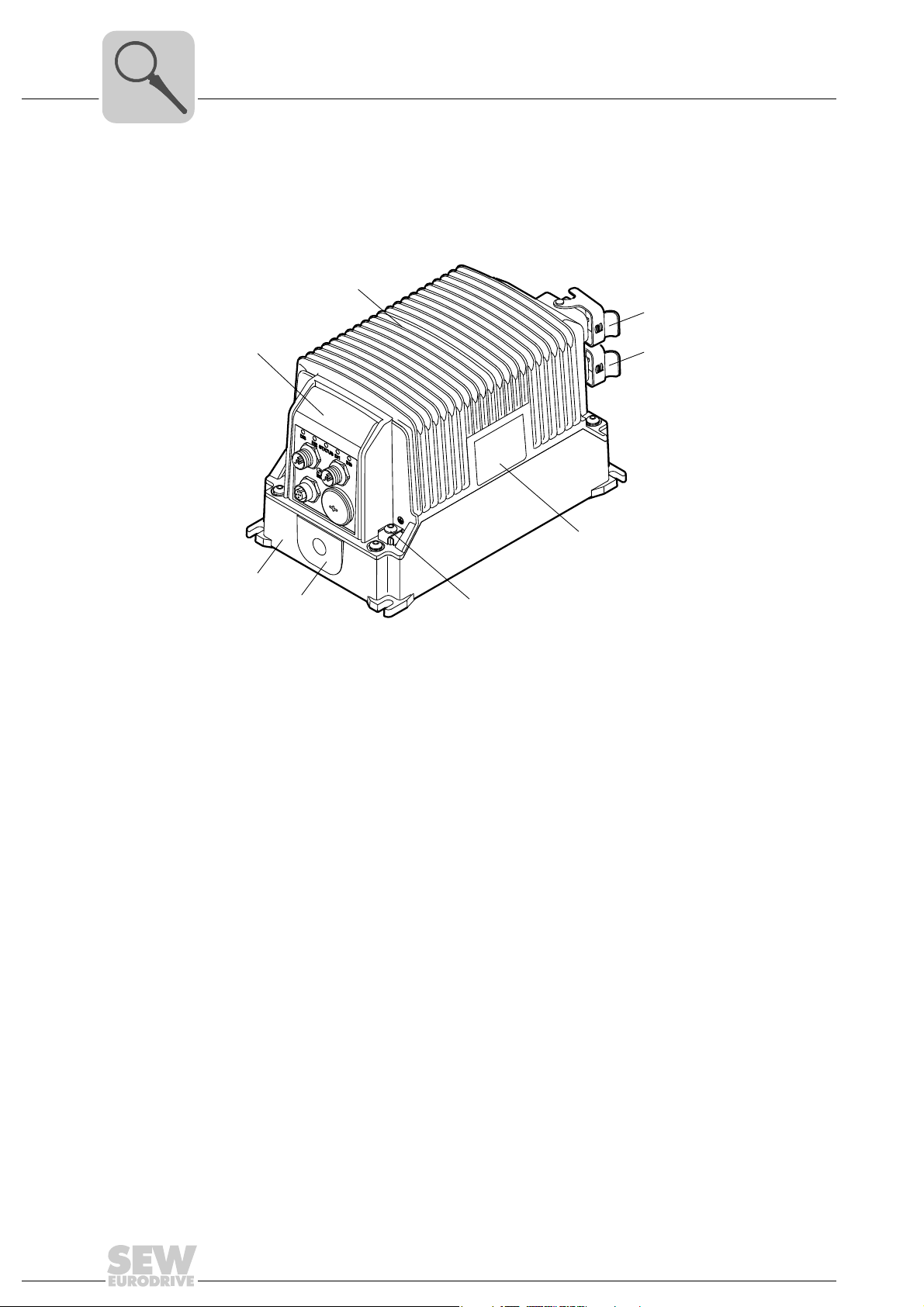
3 Unit structure
3.1 MOVIFIT® basic
Unit structure
MOVIFIT® basic
MOVIFIT® basic is a decentralized drive unit for controlling AC motors.
[2]
[3]
[1]
[5]
[8]
[7]
[1] Control unit
[2] EBOX with cooling fins and electronics (inverter or motor starter)
[3] X8 connection for motor (only with dual motor starter design)
[4] X9 connection for motor
[5] Nameplate
[6] PE connection
[7] Cable seal for cable diameter 13 – 15 mm
[8] ABOX with FieldPower contact module (connection unit)
댷 (outside)
[6]
[4]
2816397195
3.2 Variants
10
MOVIFIT® basic is available in the following variants:
• Inverter For 1 motor with CW and CCW operation and 4 setpoint speeds
• Dual motor starter For 2 motors with 1 direction of rotation each
The direction of rotation depends on the phase
sequence.
• Reversing starter For 1 motor with CW and CCW operation
®
MOVIFIT
basic is available with the following control units:
• Drives with AS-Interface
• Control unit with binary signal inputs and outputs
Operating Instructions – MOVIFIT® basic
3.3 Accessories
Unit structure
Accessories
You can order the following accessories for MOVIFIT® basic from SEW-EURODRIVE:
Accessories Part number
(SEW-EURODRIVE)
2
Motor connection cable 4 x 2.5 mm
with plug connector Q8/0 – open conductor ends
Motor connection cable 7 x 2.5 mm2, unshielded, length = 3 m
with plug connector Q8/0 – open conductor ends
You can order the following accessories for MOVIFIT
müller Interface GmbH & Co. KG (see www.weidmueller.com
Accessories Part number
Cable seal, for cables with Ø = 7.5 – 9 mm 4329610000
Cable seal, for cables with Ø = 9 – 11 mm 4323210000
Cable seal, for cables with Ø = 11 – 13 mm 4323230000
Cable seal for cables with Ø = 13 – 15 mm
Cable seal, for cables with Ø = 15 – 17 mm 4324010000
Seal (without cable entry) 4323240000
Stripping tool AM 16 (for round cables) 9204190000
Stripping tool AMF 6/10 (for flat cables) 9204180000
1) The scope of delivery of MOVIFIT® basic units comprises 2 of those cable seals.
, unshielded, length = 3 m
®
1)
basic from the company Weid-
):
1 814 874 3
1 814 992 8
(Weidmüller)
4323220000
3
Operating Instructions – MOVIFIT® basic
11
3
Unit structure
Type designations
3.4 Type designations
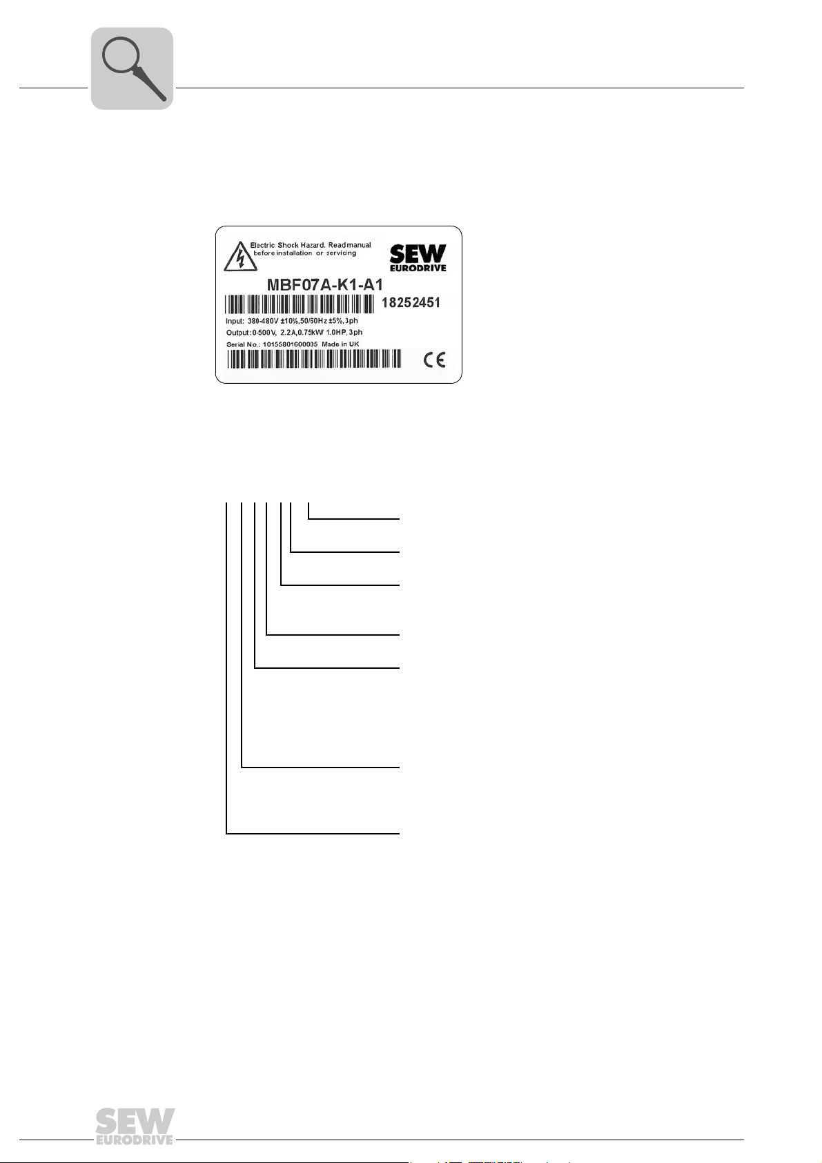
3.4.1 Nameplate
3.4.2 Type designation
The following figure gives an example of a nameplate of the MOVIFIT
®
The following table shows the MOVIFIT
basic type designation:
®
basic inverter:
3782535691
MBF07A-K1-A1
Connection module
Version
Control
K = via AS-Interface
B = binary control
Version
Motor power/variant
07 = 0.75 kW inverter
15 = 1.5 kW inverter
4R = Reversing starter
4D = Dual motor starter
Variant
F = Inverter
S = Motor starter
Unit series
MB = MOVIFIT
®
basic
12
Operating Instructions – MOVIFIT® basic

4 Mechanical installation
4.1 Installation instructions
4.1.1 General information
NOTICE
Loss of warranted degree of protection if the MOVIFIT® basic inverter is installed
incorrectly or not at all.
Damage to the MOVIFIT
• If you remove the EBOX from the ABOX, you have to protect the EBOX and the
ABOX from moisture and dust.
Note the following when installing the MOVIFIT
• Observe the general safety notes.
• Only install the MOVIFIT
support structure.
• Ensure sufficient clearance around the unit to allow for adequate cooling. Warm
outlet air of other units must not be drawn in.
Mechanical installation
Installation instructions
®
basic unit.
®
basic unit:
®
basic unit on a level, low-vibration, and torsionally rigid
4
• Strictly observe all instructions as to the technical data and the permissible conditions regarding the place of installation.
• Do only use provided attachment options when mounting the drive.
• Cover the unused plug connectors with blind caps.
The degree of protection specified in the technical data only applies for a correctly
installed MOVIFIT
4.1.2 Installation requirements
Make sure that the following requirements are met before you start installing the unit:
• The nameplate data of the MOVIFIT
• The MOVIFIT
storage).
• The ambient temperature corresponds to the specifications in chapter "Technical
Data".
• The MOVIFIT
conditions:
– Potentially explosive atmospheres
– Oils
–Acids
– Gases
®
basic unit.
®
basic unit match the voltage supply system
®
basic unit is undamaged (no damage caused by transportation or
®
basic unit must not be installed under the following harmful ambient
– Vapors
– Radiation
–etc.
Operating Instructions – MOVIFIT® basic
13
4
M1
M2
M5
M3
M4
M6
239
134
6
M5
Mechanical installation
Mounting position
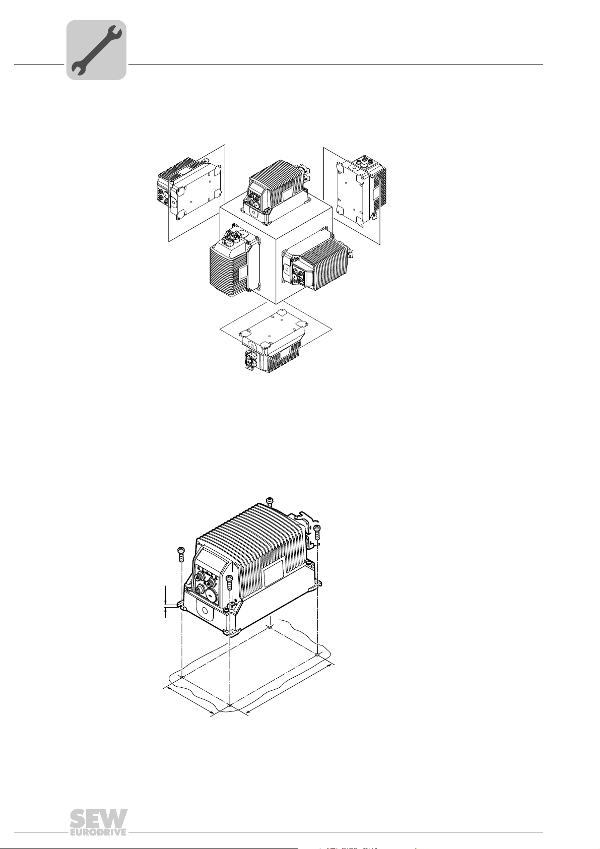
4.2 Mounting position
You can install the MOVIFIT® basic unit in any mounting position.
4.3 Installing MOVIFIT® basic
Mount the MOVIFIT® basic unit with 4 screws according to the following figure:
(Tightening torque 2.0 – 2.4 Nm (18 – 21 lb.in))
2816420235
14
9007202071159307
Operating Instructions – MOVIFIT® basic
5 Electrical installation
5.1 Installation instructions
5.1.1 Residual current device
WARNING
Electric shock due to incorrect RCD type.
Severe or fatal injuries.
®
• MOVIFIT
a residual current device (RCD) is used for protection against direct or indirect contact, only install a type B residual current device on the supply system end of the
MOVIFIT
basic can cause direct current in the protective earth conductor. When
®
basic unit.
Electrical installation
Installation instructions
5
5.1.2 Line contactor
• Do not use a conventional RCD as a protective device. Universal current-sensitive
RCDs are permitted as a protective device. During normal operation of MOVIFIT
basic units, leakage currents > 3.5 mA can occur.
• SEW-EURODRIVE recommends that you do not use RCDs. However, if a residual
current device is stipulated for direct or indirect protection against contact, observe
the above note.
NOTICE
Damage due to jogging.
®
Damage to the MOVIFIT
• Do not use the line contactor for jogging, but only for switching the MOVIFIT
unit on and off. In jog mode, use the control signals (AS-Interface bits or binary inputs).
• Observe a minimum switch-off time of 10 s for the line contactor.
• Use only a contactor of utilization category AC3 (EN 60947-4-1) as a line contactor.
basic unit.
®
basic
®
Operating Instructions – MOVIFIT® basic
15
5
M5
(2,0 – 2,5 Nm)
(18 - 21 lb.in)
Electrical installation
Installation instructions
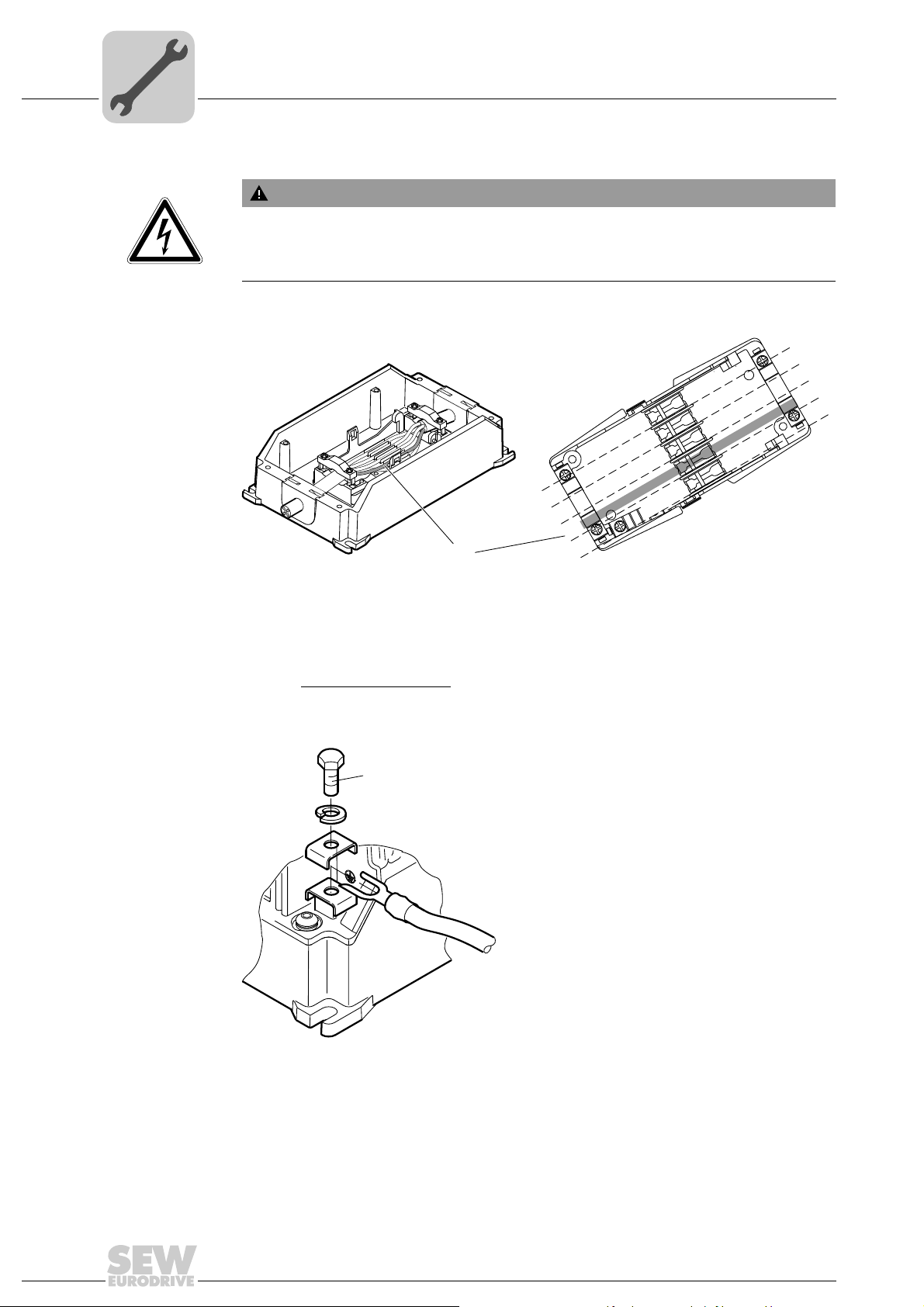
5.1.3 Notes on PE connection
WARNING
Electric shock due to incorrect connection of PE.
Severe or fatal injuries.
• Observe the following notes regarding PE connection.
PE connection in
the unit
PE connection on
the outside of the
housing
Establish a PE connection in the unit.
BR
BU
BK
GN/YE
GY
3160365451
PE
During normal operation of the MOVIFIT
BK
unused
BK or 1
WT or GY
L1
N
L2
PE
L3
®
basic inverter, earth-leakage currents
BK or 2
GN/YE
BK or 3
WT
GN
RD
≥ 3.5 mA can occur. To meet the requirements of EN 61800-5-1, you must establish 2
PE connections.
Install a second PE conductor
with a cross section of at least the cross section of the
supply system cable:
16
2816416395
Operating Instructions – MOVIFIT® basic

5.1.4 EMC-compliant installation
INFORMATION
This drive system is not designed for operation on a public low voltage supply system
that supplies residential areas.
This is a product with restricted availability in accordance with IEC 61800-3. It may
cause EMC interference. In this case, it is recommended for the operator to take
suitable measures.
For detailed information on EMC compliant installation, refer to the publication
"Electromagnetic Compatibility in Drive Engineering" from SEW-EURODRIVE.
With respect to the EMC regulation, frequency inverters cannot be operated as standalone units. Regarding EMC, they can only be evaluated when they are integrated in a
drive system. Conformity is declared for a described, CE-typical drive system. These
operating instructions contain further information.
5.1.5 Installation above 1000 m asl
®
MOVIFIT
serve the following basic conditions:
• At heights above 1000 m amsl, the nominal continuous power is reduced due to reduced cooling => I
• For heights from 2000 m to max. 4000 m amsl, observe the following notes:
– The safe disconnection of power and electronics connections can no longer be
– Connect an overvoltage protection device upstream of MOVIFIT
basic units can also be operated at an altitude of 1000 – 4000 m amsl. Ob-
assured above 2000 m. For safe disconnection, you have to take measures according to IEC 60664-1 / EN 61800-5-1.
overvoltages from category III to category II.
Electrical installation
Installation instructions
reduction by 1% per100 m.
N
®
basic to reduce
5
5.1.6 Protection devices
®
• MOVIFIT
load of the drive. External motor protection devices are not necessary.
5.1.7 UL compliant installation (in preparation)
UL and cUL approval for the MOVIFIT
basic drives are equipped with integrated protection devices against over-
®
basic unit series is in preparation.
Operating Instructions – MOVIFIT® basic
17
5
A
5.2 Topology
Electrical installation
Topology
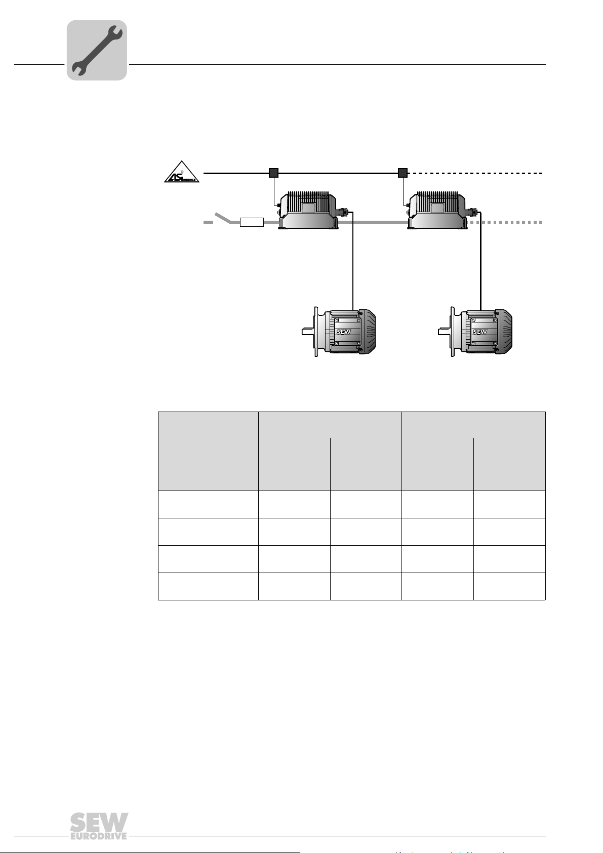
The following figure shows a typical MOVIFIT® basic drive system with AS-Interface
control:
C 3 x
380 - 480 V
K
[1]
[2] [3]
[4]
[5]
K: Line contactor
Circuit breaker for
line protection
Type Minimum con-
[1] [2] [3] [4] [5]
B16 2.5 mm
B16 2.5 mm
B20 4.0 mm
B25 6.0 mm
Power bus (line cable) Motor cable
ductor
cross section
2
AWG14
2
AWG14
2
AWG12
2
AWG10
Maximum
total length
130 m
130 m
170 m
190 m
Minimum
conductor
cross section
1.5 mm
AWG16
2.5 mm
AWG14
2.5 mm
AWG14
2.5 mm
AWG14
[4]
[5]
9007201945761931
Maximum
length
2
2
10 m
2
2
3m
3m
3m
The table shows typical characteristics at an ambient temperature of 40 °C with routing
type B2 according to EN 60204-1.
The applicable country-specific standards and regulations must also be observed for individual project planning and installation.
18
Operating Instructions – MOVIFIT® basic
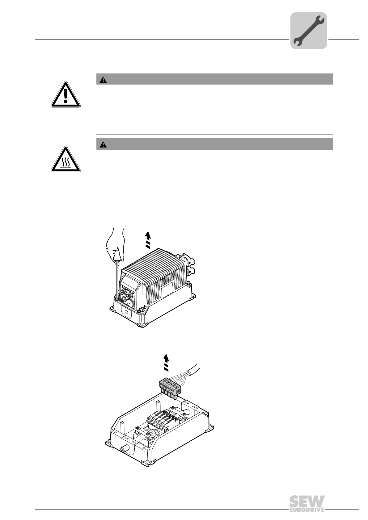
5.3 Power bus connection (line cable)
WARNING
Electric shock due to charged capacitors.
Severe or fatal injuries.
• De-energize the MOVIFIT
fore removing the EBOX from the ABOX.
• Secure the drive against unintended re-connection to the voltage supply.
• Then wait at least for 10 minutes.
WARNING
Danger of burns due to hot surfaces of the MOVIFIT® basic unit.
Severe injuries.
• Do not touch the MOVIFIT
Connect the MOVIFIT® basic unit to the power bus (line cable) as follows.
Electrical installation
Power bus connection (line cable)
®
basic drive using a suitable external cut-off device be-
®
basic until it has cooled down sufficiently.
5
1. Loosen the 4 screws and remove the EBOX from the ABOX.
2. Remove the supply system plug connector from the FieldPower
2839862283
®
contact module.
Operating Instructions – MOVIFIT® basic
9007202094605195
19
5
120
130
Electrical installation
Power bus connection (line cable)
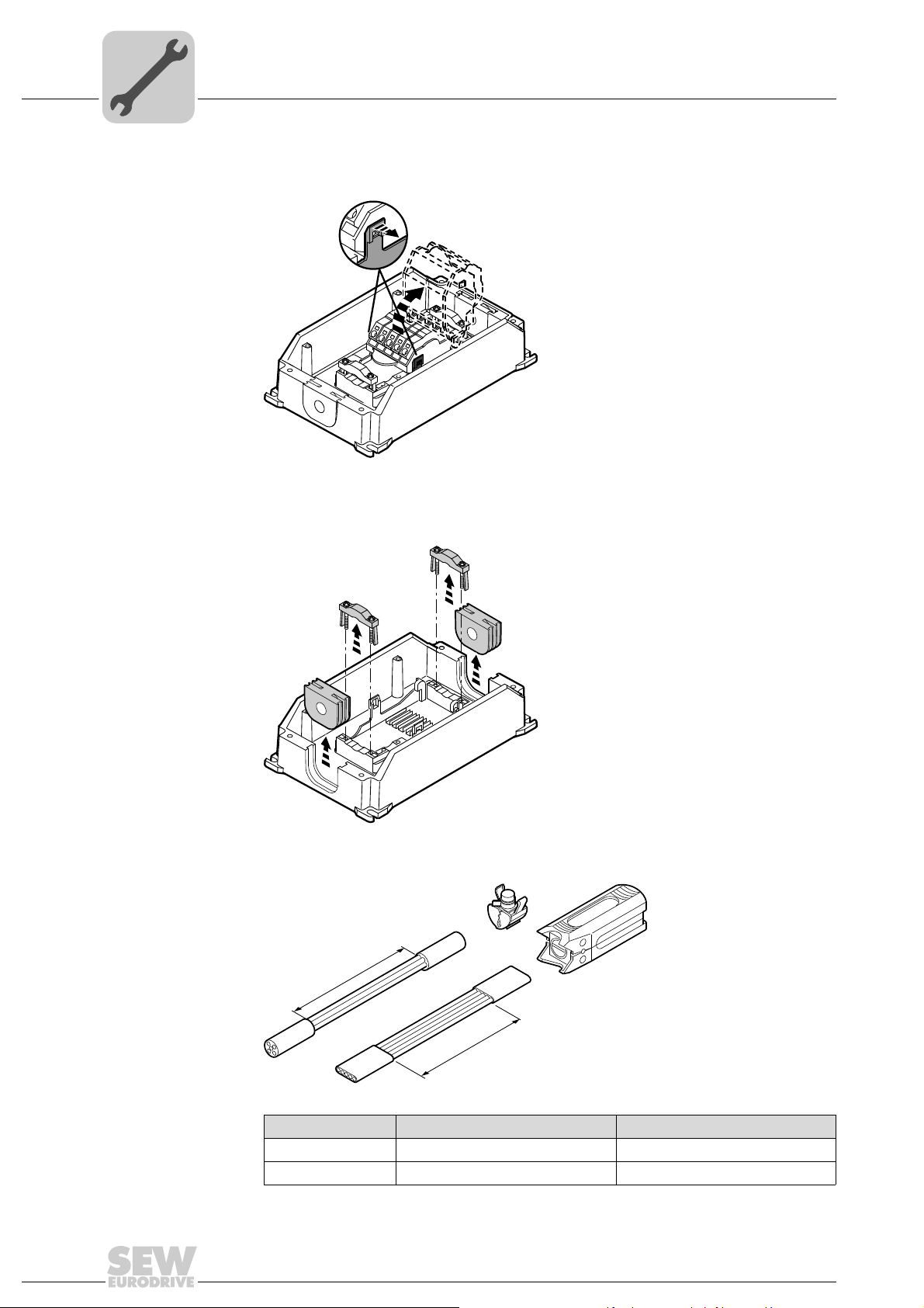
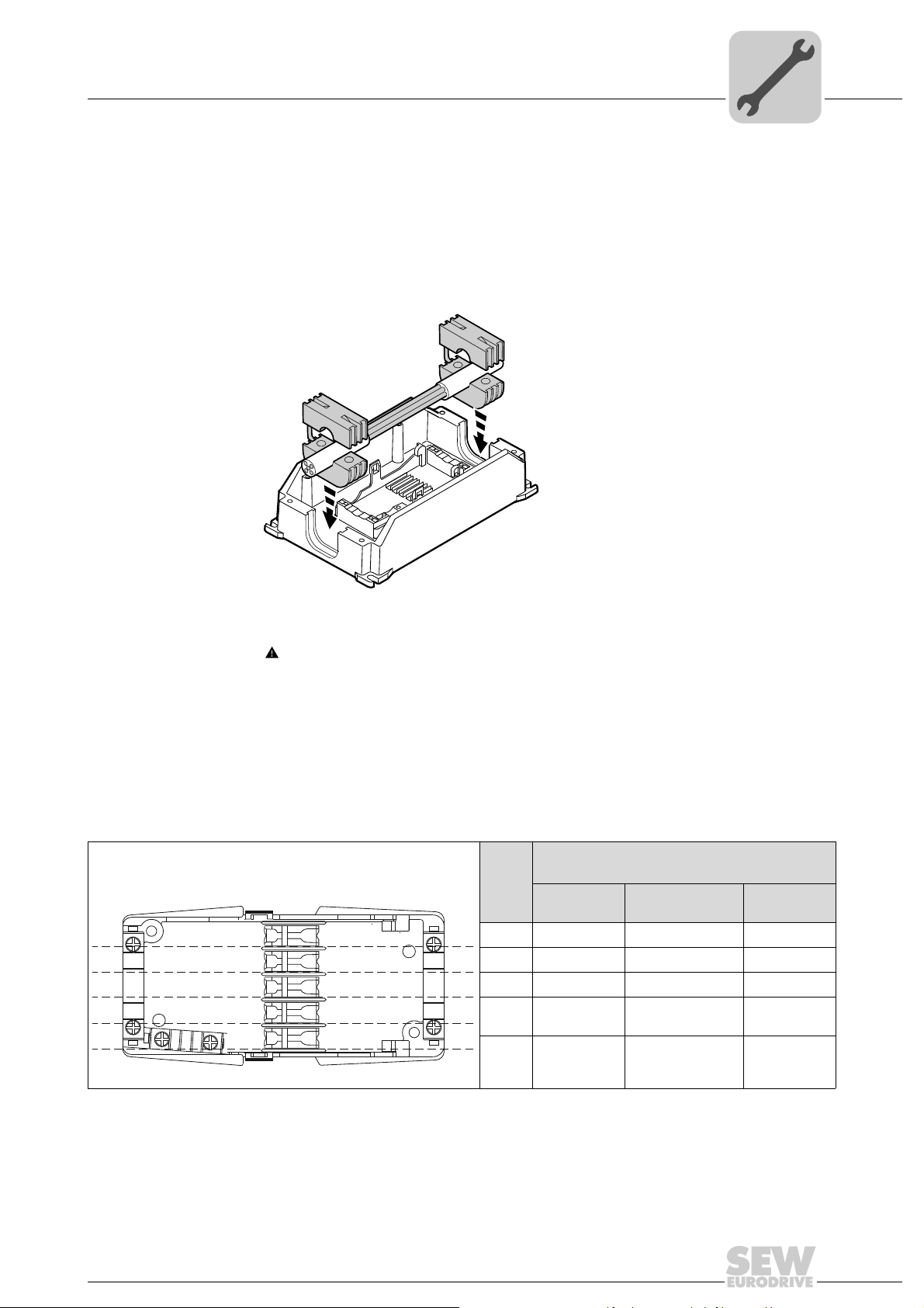
3. Pull both locking tabs to the outside and tilt up the upper part of the FieldPower® contact module.
2839866123
4. Loosen the 4 screws and remove the strain relief brackets.
Remove the two cable seals.
20
5. Remove the sheath of the line cable with a suitable stripping tool.
Line cable Stripping tool Strip length
Round cable AM 16 130 mm
Flat cable AMF 6/10 120 mm
Operating Instructions – MOVIFIT® basic
2839868043
2839869963
Electrical installation
L1
N
L2
PE
L3
L1
N
L2
PE
L3
Power bus connection (line cable)
6. Fix the cable seals around the line cable.
NOTICE Ingression of moisture or dust due to incorrect cable seal.
®
Damage to the MOVIFIT
• Only use cable seals approved for the line cable diameter.
Insert the cable seals with the line cable in the recesses in the ABOX.
basic unit.
5
2839871883
7. WARNING Risk of crushing due to wrong sense of rotation or damage due to reverse connection of phases.
Severe or fatal injuries, irreparable damage to the unit.
• Observe the following connection diagram.
• Prevent short circuits.
Insert the conductors of the line cable in the cable guides according to the following
wiring diagram:
Con-
duc-
tor
L1
N
L2
PE
L3
Conductor coloring / conductor marking
According to:
IEC 60757 UL 1277
TC-ER
Brown Black or 1 Black
Blue White or gray –
Black Black or 2 White
Green/yel-
low Green/yellow Green
Gray Black or 3 Red
UL 62
STOOW
Operating Instructions – MOVIFIT® basic
2839873803
21
5
90°
AB
Electrical installation
Power bus connection (line cable)
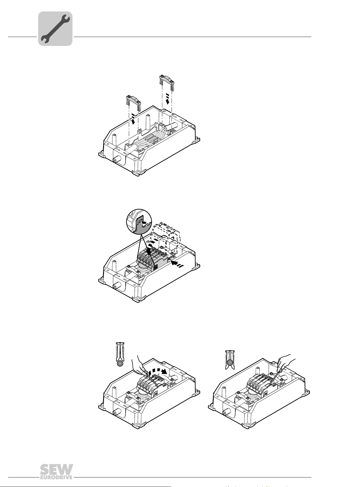
8. Screw the strain relief brackets to the ABOX and fix the line cable with the brackets
(tightening torque: 0.6 Nm, 5.3 lb.in).
2839875723
9. Place the upper part of the contact module on the hinge hooks.
Tilt down the upper part of the contact module until it latches on both sides.
2839877643
10.Use the screwdriver (blade width 3 – 3.5 mm) to lever all contacts of the insulation
displacement connector downwards.
22
Operating Instructions – MOVIFIT® basic
2839879563
Electrical installation
Power bus connection (line cable)
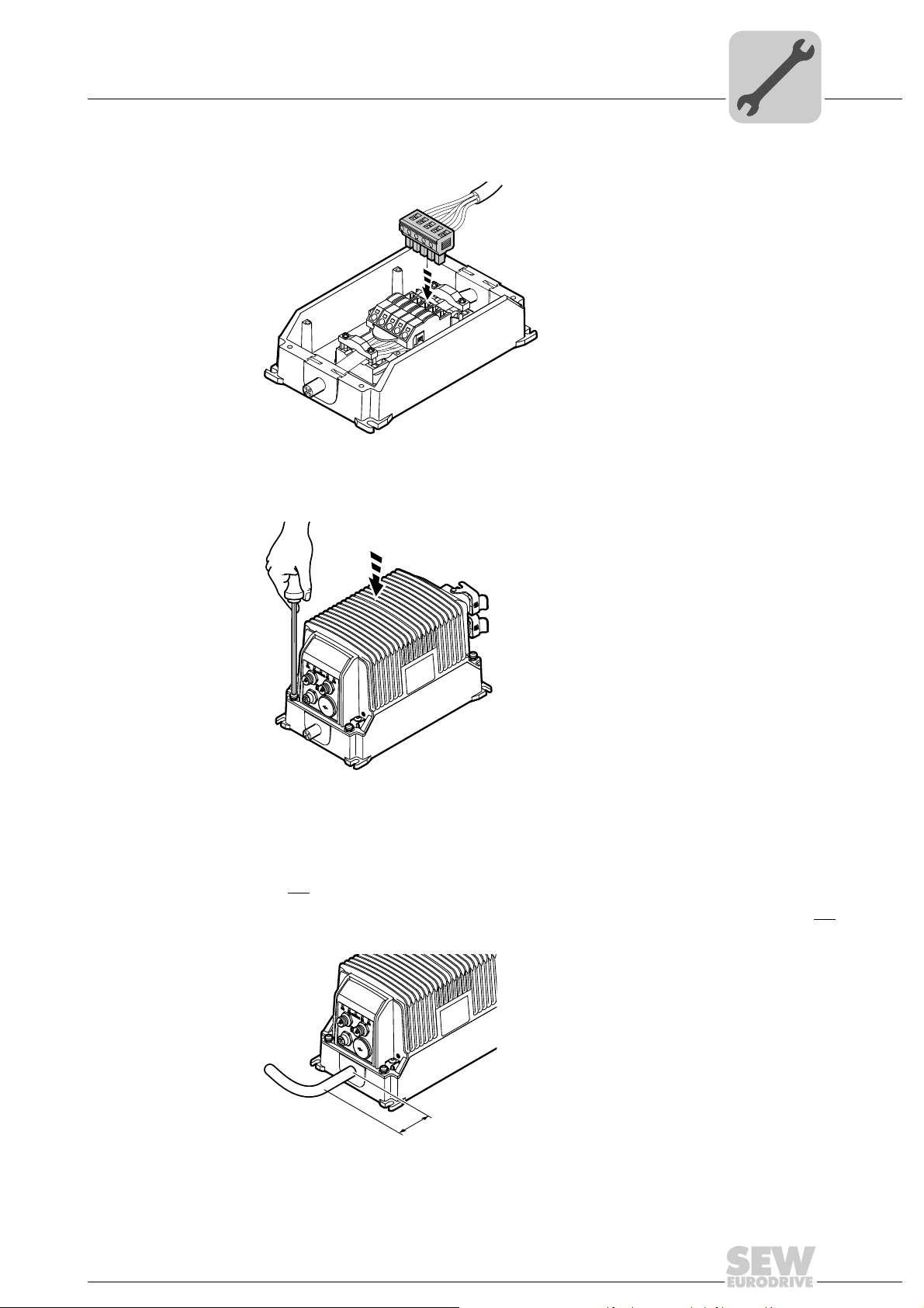
11.Plug in the line connector of the EBOX to the FieldPower® contact module.
2839881483
12.Position the EBOX on the ABOX.
Screw on the EBOX with 4 screws (tightening torque: 2 Nm, 18 lb.in).
5
NOTICE Ingression of moisture or dust when bending the line cable.
®
Damage to the MOVIFIT
• Do not
bend the line cable for the first 50 mm from the unit.
®
The MOVIFIT
bend within 50 mm of the unit.
basic unit only meets the IP54 requirements if the line cable is not
basic unit.
2839860363
3756680203
Operating Instructions – MOVIFIT® basic
23
5
[1]
X8
X9
[2]
[1]
X8
X9
Electrical installation
Motor connection
5.4 Motor connection
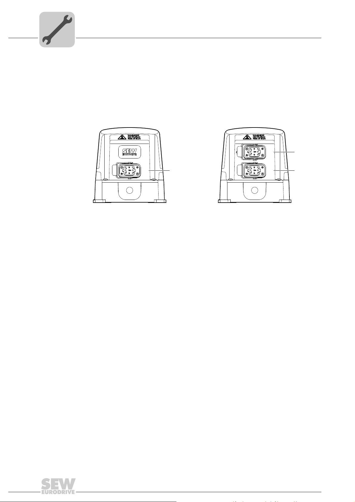
5.4.1 Motor connection variants
The following figure shows the motor plug connector variants for MOVIFIT
®
basic:
MOVIFIT
MOVIFIT
[1] X9 Motor connection
[2] X8 Motor connection
®
basic inverter
®
basic reversing starter
MOVIFIT
2816406795 2816404875
®
basic dual motor starter
24
Operating Instructions – MOVIFIT® basic
Electrical installation
8
5
3
1
2
4
PE
6
7
Motor connection
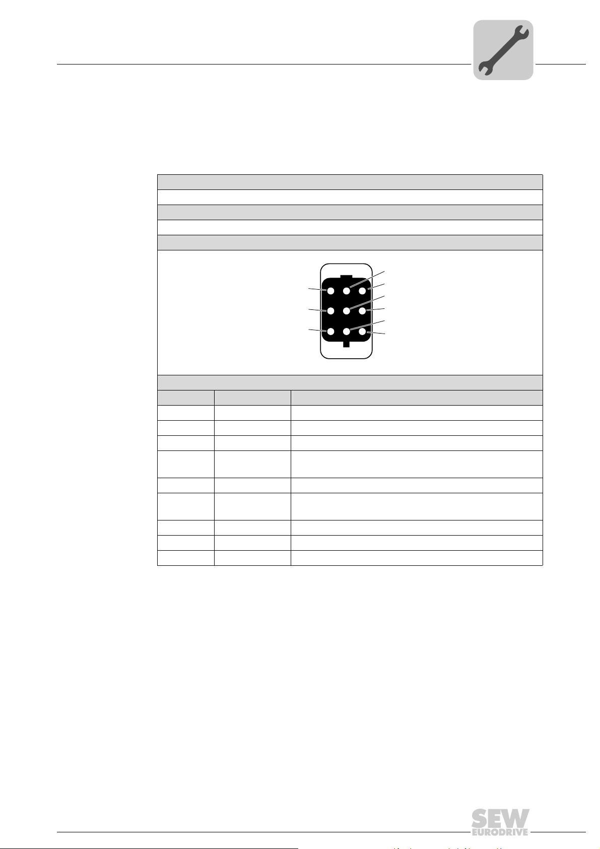
5.4.2 X9, (X8): Motor connection
The X8 plug connector is only available in conjunction with MOVIFIT
motor starter
Connection The following table provides information about this connection:
Function
Power connection for motor with brake
Connection type
Q 8/0, female
Wiring diagram
®
basic with dual-
5
Assignment
No. Name Function
1 U Motor phase U output
2 n. c. Not connected
3 W Motor phase W output
4 L1 Supply of mechanical brake
(only with MOVIFIT
5 n. c. Not connected
6 L2_S Supply of mechanical brake switched
(only with MOVIFIT
7 V Motor phase V output
8 n. c. Not connected
PE PE Protective earth
®
basic inverter)
®
basic inverter)
2441429259
Operating Instructions – MOVIFIT® basic
25
5
123
45
678
W2
U2
V2
U1
V1
W1
123
45
678
W2
U2
V2
U1
V1
W1
Electrical installation
Motor connection
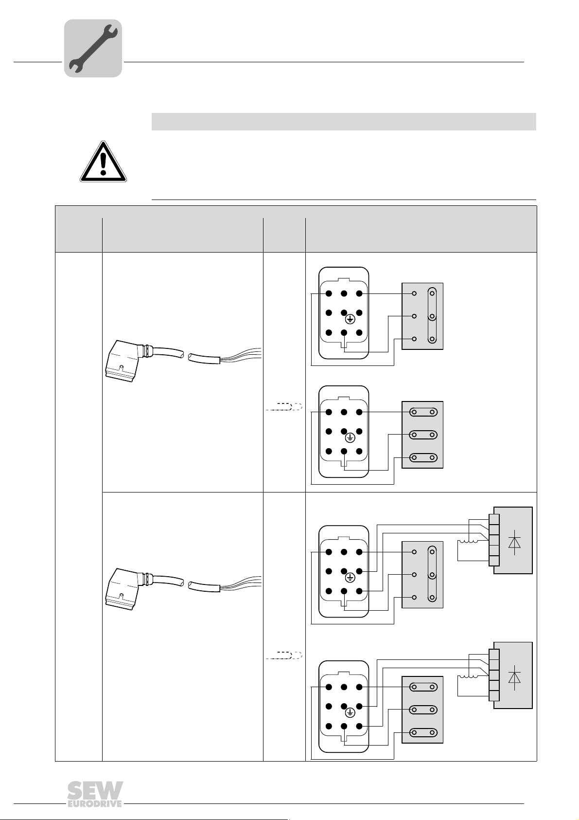
Connection cable The following table shows possible motor cables:
NOTICE
Danger in case of incorrect wiring of U1, V1, and W1 or short circuit. The motor outputs
of MOVIFIT
Irreparable damage to the MOVIFIT
• Observe the following wiring diagrams.
• Prevent any short circuits between the conductors.
Connection cable and component
MOVIFIT®
basic
Motor cable
Cable design: 4G2.5, shielded Max.
®
basic are not protected against short circuits.
Length/
Installa-
tion type
10 m
®
basic unit.
Motor connection
Motor without brake,
댴 connection
MOVIFIT
basic
inverter
Cable design: 4G2.5, unshielded
Part number: 1 814 874 3
Q 8/0 Open
®
Cable design: 7G2.5, shielded
Cable design: 7G2.5, unshielded
Part number: 1 814 992 8
Max. 3 m
Max.
10 m
Max. 3 m
Motor without brake,
Motor with brake,
123
45
U1
V1
쑶 connection
댴 connection
WH
W2
U2
RD
BU
BG
1
2
3
4
5
26
678
W1
V2
Q 8/0 Open
Motor with brake,
123
45
678
U1
V1
W1
Operating Instructions – MOVIFIT® basic
쑶 connection
WH
W2
U2
V2
RD
BU
BG
1
2
3
4
5

Connection cable and component
123
45
678
W2
U2
V2
U1
V1
W1
MOVIFIT®
basic
Motor cable
Cable design: 4G2.5, unshielded Max.
Length/
Installa-
tion type
10 m
Electrical installation
Motor connection
Motor connection
Motor without brake
5
MOVIFIT®
basic
motor
starter
Cable design: 4G2.5, unshielded
Part number: 1 814 874 3
Q 8/0 Open
3m Motor with brake
123
45
678
U1
V1
W1
W2
U2
V2
Motor with brake and BSR brake controller
123
45
678
U1
V1
W1
W2
U2
V2
BU
WH
RD
BU
WH
RD
BGE
1
BG
2
3
4
5
BGE
1
BG
2
3
4
5
For applications with regenerative mode, SEW-EURODRIVE recommends the BSR brake controller.
Mating connector Use a type Q8/0 plug connector for pre-fabricating these motor cables:
INFORMATION
Note the following when using a mating connector with metallic housing:
• Ensure a suitable shield connection.
• Connect the housing of the mating connector with PE.
Operating Instructions – MOVIFIT® basic
27

5
DI3 DI2 DI1 DI0
STATUS
[5]
[8] [7]
[6]
Electrical installation
Control unit connection
5.5 Control unit connection
The following figure shows the control unit variants for MOVIFIT®basic:
MOVIFIT
®
basic with AS-Interface MOVIFIT®basic with binary control
[1]
DI3 DI2
[4] [3]
STATUS
[2]
AS-Interface
9007202071153547 2816402955
[1] X22 Binary input sensor 2 [5] X12 Signal inputs DI2 + DI3
[2] X21 AS-Interface connection [6] X11 Signal inputs DI0 + DI1
[3] X50 Diagnostic interface [7] X50 Diagnostic interface
[4] X23 Binary input sensor 3 [8] X13 Signal outputs DO0 + DO1
28
Operating Instructions – MOVIFIT® basic

Connections of MOVIFIT®basic with AS-Interface
2
1
4
3
5.6 Connections of MOVIFIT
5.6.1 X21: AS-Interface connection
The following table provides information about this connection:
Function
AS-Interface – input
Connection type
M12, 4-pole, male, A-coded
Wiring diagram
Assignment
No. Name Function
1 AS-Interface + AS-Interface +
2 n. c. Not connected
3 AS-Interface − AS-Interface −
4 n. c. Not connected
Electrical installation
®
basic with AS-Interface
5
2384154763
5.6.2 X22: Binary input sensor 2
The following table provides information about this connection:
Function
Binary input sensor 2
Connection type
M12, 5-pole, female, A-coded
Wiring diagram
Assignment
No. Name Function
1 +24 V DC 24 V output (sensor supply)
2 n. c. Not connected
3 0V24 0V24 reference potential
4 DI2 Binary input sensor 2
5 PE Equipotential bonding/protective earth conductor
1
4
2
3
5
2264816267
Operating Instructions – MOVIFIT® basic
29

5
1
6
Electrical installation
Connections of MOVIFIT®basic with AS-Interface
5.6.3 X23: Binary input sensor 3
The following table provides information about this connection:
Function
Binary input sensor 3
Connection type
M12, 5-pole, female, A-coded
Wiring diagram
Assignment
No. Name Function
1 +24 V DC 24 V output (sensor supply)
2 n. c. Not connected
3 0V24 0V24 reference potential
4 DI3 Binary input sensor 3
5 PE Equipotential bonding/protective earth conductor
5.6.4 X50: Diagnostic interface
The following table provides information about this connection:
Function
Diagnostics and programming interface
Connection type
RJ11 (6P6C)
Wiring diagram
1
4
2
3
5
2264816267
3163123211
Assignment
No. Name Function
1 n. c. Not connected
2 RS+ RS-485 data cable (+)
3RS − RS-485 data cable (–)
4 +24 V DC 24 V output for keypad
5 0V24 0V24 reference potential for keypad
6 n. c. Not connected
30
Operating Instructions – MOVIFIT® basic

Connections of MOVIFIT®basic with binary control
2
1
4
3
2
1
4
3
®
5.7 Connections of MOVIFIT
5.7.1 X11: Signal inputs 0 and 1 of MOVIFIT® basic
The following table provides information about this connection:
Function
Binary inputs 0 and 1
Connection type
M12, 4-pole, male, A-coded
Wiring diagram
Assignment
No. Name Function
1 n. c. Not connected
2 DI1 Binary input 1
3 0V24 0V24 reference potential
4 DI0 Binary input 0
basic with binary control
Electrical installation
5
2718233355
5.7.2 X12: Signal inputs 2 and 3 of MOVIFIT
The following table provides information about this connection:
Function
Binary inputs 2 and 3
Connection type
M12, 4-pole, male, A-coded
Wiring diagram
Assignment
No. Name Function
1 n. c. Not connected
2 DI3 Binary input 3
3 0V24 0V24 reference potential
4 DI2 Binary input 2
®
basic
2718233355
Operating Instructions – MOVIFIT® basic
31

5
1
4
3
2
5
1
6
Electrical installation
Connections of MOVIFIT®basic with binary control
5.7.3 X13: Signal outputs 0 and 1 of MOVIFIT® basic
The following table informs about this connection:
Function
Binary outputs 0 and 1
Connection type
M12, 5-pole, female, A-coded
Wiring diagram
Assignment
No. Name Function
1 +24 V DC 24 V output
2 DO1 Binary output 1 (manual mode)
3 0V24 0V24 reference potential
4 DO0 Binary output 0 (ready signal)
5 PE Equipotential bonding/protective earth conductor
0: MOVIFIT
1: Manual control of MOVIFIT
0: MOVIFIT
1: MOVIFIT
®
basic control via control signals
®
basic is not ready
®
basic is ready
®
2264816267
basic
5.7.4 X50: Diagnostic interface
The following table informs about this connection:
Function
Diagnostics and programming interface
Connection type
RJ11 (6P6C)
Wiring diagram
Assignment
No. Name Function
1 n. c. Not connected
2 RS+ RS-485 data line (+)
3RS − RS-485 data cable (–)
4 +24 V DC 24 V output for keypad
5 0V24 0V24 reference potential for keypad
6 n. c. Not connected
3163123211
32
Operating Instructions – MOVIFIT® basic

Electrical installation
Connection of operator terminals LT-BG and MB-LC
5.8 Connection of operator terminals LT-BG and MB-LC
MOVIFIT® basic units are equipped with an X50 diagnostic interface (RJ11 socket).
The diagnostics interface is located in the connection block of the control unit.
You must remove the screw plug before plugging in the connector into the diagnostic
interface.
WARNING Danger of burns due to hot surfaces of the MOVIFIT
Severe injuries.
®
• Wait for the MOVIFIT
NOTICE Loss of the ensured degree of protection if the screw plug of the diagnostic interface X50 is not installed.
Damage to the MOVIFIT
basic unit to cool down sufficiently before touching it.
®
basic unit.
®
basic unit.
5
• If there is no screw plug covering the diagnostic interface, you have to make sure that
no moisture can ingress into the MOVIFIT
Use the cable enclosed with the operator terminal to connect the operator terminal to
the MOVIFIT
Scope of delivery:
Type Part number Scope of delivery
LT-BG 1 820 864 9 – LT-BG operator terminal
MB-LC 2 820 126 4 – MB-LC operator terminal
®
basic unit.
®
basic unit.
– Cable with RJ11 – RJ11 plug connectors
– Cable with RJ45 – RJ11 plug connectors
Operating Instructions – MOVIFIT® basic
18014401325896459
33

5
5.9 PC connection
Electrical installation
PC connection
The MOVIFIT® basic inverter is equipped with an X50 diagnostics interface (RJ-11
socket) for startup, parameterization and service.
The diagnostics interface is located in the connection block of the control unit.
You must remove the screw plug before plugging in the connector into the diagnostic
interface.
®
WARNING Danger of burns due to hot surfaces of the MOVIFIT
Severe injuries.
®
• Wait for the MOVIFIT
basic unit to cool down sufficiently before touching it.
NOTICE Loss of the ensured degree of protection if the screw plug of the diagnostic interface X50 is not installed.
®
Damage to the MOVIFIT
basic unit.
basic unit.
• If no screw plug is covering the diagnostic interface, you have to make sure that no
moisture can ingress into the MOVIFIT
®
basic unit.
The diagnostic interface can be connected to a conventional PC/laptop with the following accessories:
• USB11A interface adapter
•and
OP LT 003 C adapter
Scope of delivery:
Type Part number Scope of delivery
USB11A 0 824 831 1 – USB11A interface adapter
– USB cable
– Cable with RJ10 – RJ10 plug connectors
OP LT 003 C 1 824 368 1 – OP LT 003 C adapter
with DC 24 V -> DC 5 V voltage converter
– Cable with RJ45 – RJ11 plug connectors
34
PC +
MOVITOOLS
USB
®
USB11A
RJ10
OP LT 003 C
Operating Instructions – MOVIFIT® basic
RJ45
RJ11
MOVIFIT basic
9007202071149707
®

6Startup
00
I
6.1 Important notes on startup
INFORMATION
You must comply with the general safety notes in chapter "Safety notes" during
startup.
WARNING
Risk of crushing due to missing or defective protective covers.
Severe or fatal injuries.
• Install the protective covers of the plant according to the instructions, also see the
operating instructions of the gear unit.
• Never start up the drive if the protective covers are not installed.
WARNING
Electric shock due to dangerous voltages in the ABOX.
Severe or fatal injuries.
• De-energize the MOVIFIT
fore removing the EBOX.
• Secure the MOVIFIT
supply.
• Wait for at least 10 minutes before removing the EBOX.
Startup
Important notes on startup
®
basic unit using a suitable external cut-off device be-
®
basic unit against unintended re-connection to the voltage
6
WARNING
Danger of burns due to hot surfaces of the MOVIFIT® basic unit.
Severe injuries.
®
• Do not touch the MOVIFIT
basic until it has cooled down sufficiently.
WARNING
Unit malfunction due to incorrect unit setting.
Severe or fatal injuries.
• Observe the startup notes.
• The installation must only be carried out by qualified personnel.
• Use only settings that are consistent with the function.
INFORMATION
To ensure fault-free operation, do not disconnect or connect power or signal cables
during operation.
Operating Instructions – MOVIFIT® basic
35

6
00
I
6.2 Requirements
Startup
Requirements
The following conditions apply to startup:
®
• The MOVIFIT
cally.
• Appropriate safety measures prevent the drives from starting up unintentionally.
• Appropriate safety measures must be taken to prevent risk of injury or damage to the
machine.
The following hardware must be available for startup and parameterization of the
MOVIFIT
• Operator terminal LT-BG, see chapter "Connecting the operator terminals LT-BG
• or PC/laptop, see chapter "PC connection"
®
basic inverter:
and MB-LC"
basic unit must be installed correctly both mechanically and electri-
The following software must be available on the PC or laptop for startup and parameterization of the MOVIFIT
• LT Shell", version 3.20 or later
®
basic inverter:
INFORMATION
For startup of the MOVIFIT® basic motor starter, you do not require a PC/laptop and
software.
36
Operating Instructions – MOVIFIT® basic

Startup procedure for the MOVIFIT® basic inverter
00
I
6.3 Startup procedure for the MOVIFIT
Proceed as follows to startup the MOVIFIT® basic inverter:
1. Check the connection of the MOVIFIT
See chapter "Electrical Installation".
2. Make sure that the motor cannot start
e.g. by unplugging the motor connector from the MOVIFIT
3. Switch on the line voltage.
The "Status" LED is now illuminated.
4. Connect the LT-BG operator terminal or the PC to the MOVIFIT
See chapter "Connecting the operator terminals LT-BG and MB-LC" (page 33)
or chapter "PC connection" (page 34).
WARNING During the auto-tune phase in vector control, the motor axis briefly
rotates.
If you set the parameter P4-02 Auto-tune = "1", the inverter performs a calibration
process (Auto-tune). The inverter releases the brake and the motor briefly rotates.
®
basic inverter
®
basic unit.
Startup
®
basic unit.
®
6
basic unit.
Severe injuries.
• During the auto-tune phase, observe a sufficient safety distance to all parts driven
by the motor.
5. Set the following parameters:
Motor parameters:
For V/f control
• P1-07 = Nominal motor voltage
• P1-08 = Nominal motor current
• P1-09 = Nominal motor frequency
System parameters:
• P1-03 = Acceleration ramp
• P1-04 = Deceleration ramp
• P1-11 = Speed n1
• P2-02 = Speed n2
• P2-03 = Speed n3
• P2-04 = Speed n4
See chapter "Parameterization with LT-BG operator terminal" (page 43).
or chapter "Parameterization with PC" (page 45).
6. Make sure the screw plug of the diagnostics interface has a seal and screw it in.
For vector control
• P1-07 = Nominal motor voltage
• P1-08 = Nominal motor current
• P1-09 = Nominal motor frequency
• P4-01 = Control mode
• P4-02 = Auto-tune
• P4-05 = motor power factor
NOTICE Loss of the ensured degree of protection if the screw plug of the diagnostic
interface is not installed or not installed correctly.
Damage to the MOVIFIT
• Make sure the screw plug of the diagnostics interface has a seal and screw it in.
7. Switch off the line voltage.
8. Set the AS-Interface slave address of the MOVIFIT
basic with AS-Interface).
See chapter "Assigning the AS-Interface address" (page 40).
Operating Instructions – MOVIFIT® basic
®
basic unit
®
basic unit (only for MOVIFIT
®
37

6
00
I
Startup
Startup procedure for the MOVIFIT® basic inverter
9. Start up the higher-level controller.
®
10.Plug in the motor connector at the MOVIFIT
11.Switch on the line voltage.
®
You can now control the MOVIFIT
signals or AS-Interface).
basic drive with the higher-level controller (via binary
basic.
38
Operating Instructions – MOVIFIT® basic

6.4 MOVIFIT
00
I
MOVIFIT® basic motor starter – startup procedure
®
basic motor starter – startup procedure
WARNING
Electric shock due to dangerous voltages in the ABOX.
Severe or fatal injuries.
®
• De-energize the MOVIFIT
fore removing the EBOX.
• Secure the MOVIFIT
supply.
Proceed as follows to startup the MOVIFIT® basic motor starter:
1. Check the connection of the MOVIFIT
See chapter "Electrical Installation".
basic unit using a suitable external cut-off device be-
®
basic unit against unintended re-connection to the voltage
®
basic unit.
Startup
6
Reversing starter:
Dual motor starter:
2. Set the I
= nominal motor current as listed on the motor nameplate
I
Mot
= nominal output current as listed on the MOVIFIT® basic nameplate
I
N
/ IN ratio at the I
Mot
NOTICE Damage due to incorrect setting of I
potentiometer (factory setting: about 100%).
Motor
potentiometer. The potentiometer
Motor
setting protects the motor against overload.
Damage to the motor.
• When setting the potentiometer, observe the current rating on the nameplates of
®
60
20
basic unit.
60
40
20
80
100
60
40
20
80
100
80
100
I [A]
Motor
10
8
6
4
2
0
0 20 40 60 80 100
9007203014544907
I [A]
Motor
5
4
3
2
the motor and the MOVIFIT
40
[1]
7
7
7
4
0
5
6
7
1
5
[1] Potentiometer setting I
Operating Instructions – MOVIFIT® basic
/ IN in %
Mot
1
0
0 20 40 60 80 100
7774056715
[1]
39

6
00
I
Startup
Assigning the AS-Interface slave address
3. Make sure that the motor cannot start
e.g. by unplugging the motor connector(s) from the MOVIFIT
4. Set the AS-Interface slave address of the MOVIFIT
basic with AS-Interface).
See chapter "Assigning the AS-Interface address" (page 40).
5. Start up the higher-level controller.
6. Plug in the motor connector(s) at MOVIFIT
7. Switch on the line voltage.
You can now control the MOVIFIT
signals or AS-Interface).
6.5 Assigning the AS-Interface slave address
SEW-EURODRIVE supplies MOVIFIT®basic with AS-Interface with address 0.
®
basic unit.
®
basic unit (only for MOVIFIT
®
basic.
®
basic drive with the higher-level controller (via binary
®
You have the following options for assigning the AS-Interface address of MOVIFIT
basic (address 1 - 31):
• Addresses are assigned automatically within a configured AS-Interface system
®
when replacing a MOVIFIT
basic drive.
The following prerequisites must be fulfilled:
®
–The new MOVIFIT
– If you need to replace multiple MOVIFIT
basic drive must have address 0.
®
basic drives, you must exchange them
individually (one after another).
• Manual address assignment via the plant master
Connect the drives to the AS-Interface cable one after another. Doing so prevents
®
several MOVIFIT
basic drives being assigned the same AS-Interface address.
• Manual address assignment using a hand-held AS-Interface programming
device.
®
Observe the notes in the following section when connecting the MOVIFIT
basic
drive to the AS-Interface cable.
®
40
Operating Instructions – MOVIFIT® basic

Assigning the AS-Interface slave address
2
1
4
3
A
B
MOVIFIT basic
[1]
®
MOVIFIT basic
®
00
I
6.5.1 Assigning the slave address using a hand-held programming device
Hand-held AS-Interface programming devices offer the following functions:
• Reading out and changing an AS-Interface slave address
• Reading out the AS-Interface profile
• Reading out and changing the data and parameter bits
• Function check and test run.
Startup
6
When using a hand-held programming device, you need a connection cable that fits onto
®
the AS-Interface plug connector X21 of MOVIFIT
basic (see the following figure).
1: AS-Interface +
2. n. c.
3: AS-Interface −
4: n. c.
2384154763
Example:
1. Disconnect the AS-Interface nodes from the AS-Interface network one at a time and
assign addresses via the hand-held programming device (A).
2. Then reconnect the respective AS-Interface node to the AS-Interface network (B).
9007202092542475
[1] AS-Interface hand-held programming device
Operating Instructions – MOVIFIT® basic
41

6
00
I
Startup
Parameterization with LT-BG keypad
6.6 Parameterization with LT-BG keypad
6.6.1 Description of LT-BG keypad
Function You can use the LT-BG keypad for startup, parameterization and manual operation of
MOVIFIT
about the state of the drive.
Features • Illuminated display
• Keypad with 5 keys
• Connection cable
Key assignment The following figure shows the key assignment of the LT-BG operator terminal:
®
basic inverters. In addition to that, the keypad displays important information
Key Navigate • Switch menu
• Saving parameter values
• Show real-time information
Key Up • Increase speed
• Increase parameter values
Key Down • Decrease speed
• Decrease parameter values
Key Stop • Stop the drive
• Reset the drive
Key Start • Enabling the drive
• Changing the direction of rotation
2669822603
42
Operating Instructions – MOVIFIT® basic

6.6.2 Parameterization
00
I
Proceed as follows to change the parameter values:
Startup
Parameterization with LT-BG keypad
6
1. Check the connection of the MOVIFIT
See chapter "Electrical Installation".
2. Connect the LT-BG operator terminal to the MOVIFIT
See chapter "Connecting the operator terminals LT-BG and MB-LC" (page 33)
3. Make sure that the motor cannot start
e.g. by unplugging the motor connector(s) from the MOVIFIT
Switch on the line voltage.
4.
After initialization, the operator terminal shows the rotational fre-
quency "H", the output current "A", or the motor power "P".
To change the display, briefly press the key.
Use the key to activate the parameter mode.
5.
(Press the key for more than 1 s)
Use the key and the key to select the desired parameter.
6.
Use the key to activate the setting mode.
7.
®
basic unit.
®
basic unit.
®
basic unit.
H 50.0
P 1 - 0 1
P 1 - 0 3
5.0
Use the key and the key to set the required parameter
8.
value.
Use the key to quit the setting mode.
9.
Use the key to quit the parameter mode.
10.
(Press the key for more than 1 s)
The operator terminal shows "StoP", "H ", "A ", or "P ".
11. Switch off the line voltage.
®
12. Plug in the motor connector(s) at the MOVIFIT
13. NOTICE Damage due to missing or incorrectly mounted screw plug of the diagnostics interface X50. The degree of protection of MOVIFIT
"Technical data" only applies if the screw plug of the diagnostic interface is mounted
correctly.
®
Damage to the MOVIFIT
• Once you have finished working with the operator terminal, unplug the connector
from the diagnostics interface.
• Screw the screw plug of the diagnostics interface back in with the seal.
For a description of the parameters, refer to chapter "Parameter list – MOVIFIT
inverter"
basic unit.
basic unit.
®
basic specified in chapter
2.0
P 1 - 0 3
S t o P
®
basic
Operating Instructions – MOVIFIT® basic
43

6
00
I
6.6.3 Reset parameters to default settings
Startup
Parameterization with LT-BG keypad
To reset the parameters to their default value, proceed as follows:
1. Check the connection of the MOVIFIT
See chapter "Electrical Installation".
2. Connect the LT-BG operator terminal to the MOVIFIT
See chapter "LT-BG operator terminal connection".
3. Press the 3 keys , , and simultaneously for at least 2 s.
After 2 s, the display shows "P-def".
4. Press the key to confirm the factory settings.
®
basic unit.
®
basic unit.
44
Operating Instructions – MOVIFIT® basic

6.7 Parameterization with the PC
00
I
(Only for MOVIFIT® basic inverter)
6.7.1 Parameterization with LT Shell software
Proceed as follows to change the parameter values via the PC:
1. Check the connection of the MOVIFIT
See chapter "Electrical Installation".
2. Connect the PC/laptop to the MOVIFIT
See chapter "PC connection".
3. Start the LT Shell V4.0.exe software.
4. Select the COM port of the PC/laptop, the MOVIFIT
Startup
Parameterization with the PC
®
basic unit.
®
basic unit.
®
basic unit is connected to.
6
5. Choose the communication type RS485.
9007203037920011
7828289163
Operating Instructions – MOVIFIT® basic
45

6
00
I
Startup
Parameterization with the PC
6. Read the parameter set with the button of the MOVIFIT® basic.
The parameter menu is displayed:
[1] [2] [3] [4] [5] [6] [7]
[1] Open parameter set
[2] Save parameter set on PC
[3] Shows the units in the network
[4] Restore factory settings of the unit
[5] Read parameter set from MOVIFIT
[6] Transmit parameter set to MOVIFIT
[7] Select parameter group
®
basic unit.
®
basic unit.
7. Select the required parameter group [7].
8. Double-click the required parameter.
9. Enter the new parameter value into the input field.
10.Transmit the parameter set from the PC to the MOVIFIT
ton.
9007203038730891
®
basic using the but-
46
Operating Instructions – MOVIFIT® basic

6.7.2 Real-time edit mode
Add Virtual Drive
Scan Drive Nezwork
Real-Time Edit Mode
Scans for Drives on the Network
Add Virtual Drive
Scan Drive Network
Real-Time Edit Mode
Scans for Drives on the Network
Add Virtual Drive
Offline Mode
Real-Time Edit Mode
Enables Real-Time Edit Mode
Enables Real-Time Edit Mode
Add Virtual Drive
Offline Mode
Real-Time Edit Mode
00
I
Startup
Parameterization with the PC
6
In real-time edit mode, the parameter changes become active immediately in the
®
MOVIFIT
basic inverter.
WARNING
Risk of crushing if the drive starts up unintentionally and risk of impact due to sudden
changes in velocity. When the drive is enabled, a parameter change affects the drive
system immediately.
Severe or fatal injuries.
• Make sure that the drive is inhibited
• Take additional safety precautions depending on the application to avoid injury to
people and damage to machinery.
Proceed as follows to change the parameter values in real-time edit mode:
®
1. If the MOVIFIT
basic unit has not been set up yet in the LT Shell software, carry
out the steps 1 to 5 of chapter "Parameterization with LT Shell software".
2. Scan the network for existing drives.
before you activate the real-time edit mode.
Operating Instructions – MOVIFIT® basic
7832409995
3. Activate the real-time edit mode by clicking the [Real-time edit mode] button.
7828297995
47

6
Add Virtual Drive
Offline Mode
Real-Time Edit Mode
Enter offline mode
Add Virtual Drive
Offline Mode
Real-Time Edit Mode
Enter offline mode
00
I
Startup
Parameterization with the PC
4. Select the required parameter group.
5. Double-click the required parameter.
6. Enter the new parameter value into the input field.
7. Exit the real-time edit mode by activating offline mode with the [Offline mode] button.
7832413579
48
Operating Instructions – MOVIFIT® basic

Parameter directory of the MOVIFIT® basic inverter
00
I
6.8 Parameter directory of the MOVIFIT
®
basic inverter
Startup
6
The following tables show the unit-relevant parameters. The keypad shows additional
parameters that are without function for MOVIFIT
®
basic.
6.8.1 Standard parameters
The following table shows the standard parameters:
No. Name Range Standard Description
P1-01 Upper speed limit
[Hz] or [rpm]
P1-02 Lower speed limit
[Hz] or [rpm]
P1-03 Acceleration ramp 0.0 s – 3000 s 5.0 s Time for acceleration along the
P1-04 Deceleration ramp 0.0 s – 3000 s 5.0 s Time for deceleration from the nom-
P1-06 Energy optimization
(for V/f mode only)
P1-07 Nominal motor voltage 0.2 – 500 V 400 V Set the nominal motor voltage
P1-08 Nominal motor current 0.4 – 2.2 A (with MBF07A..) 2.2 A Set the nominal motor current
P1-09 Nominal motor fre-
quency
P1-10 Nominal motor speed 0 – 30000 rpm 0 Set the nominal motor speed
P1-11 Speed n1 -P1-01 – +P1-01 50 Hz The drive runs with this speed in jog
P1-12 Control mode of the
drive
P1-13 Error log The 4 most recent errors are
P1-02 – P1-09 x 5
(up to 2000 Hz max.)
0 – P1-01 0.0 Hz Setting the lower speed limit.
0: Deactivated 0 With P1-06 = "1", the unit reduces
1: Activated
0.8 – 4.1 A (with MBF15A..) 4.1 A
25 – 500 Hz 50 Hz Set the nominal motor frequency
0: Binary signals or
AS-Interface
1: Manual mode
(only clockwise)
2: Manual mode
(CW and CCW operation)
logged.
50.0 Hz Setting the upper speed limit.
The display in [Hz] or [rpm]
depends on parameter P1-10.
The display in [Hz] or [rpm]
depends on parameter P1-10.
ramp from 0 to the nominal frequency (P1-09).
inal frequency (P1-09) to 0.
At P1-04 = "0", the maximum decel-
eration is realized.
the supplied motor voltage in case
of light loads.
according to the motor nameplate.
With P1-07 = "0", voltage compen-
sation is deactivated.
according to the motor nameplate
[A].
according to the motor nameplate
[Hz].
With P1-10 ≠ 0, all speed-related
parameters are displayed in rpm.
mode, or when the speed n1 was
selected by the higher-level controller.
0 Setting the control mode
Display of
the most
recent error
The most recent error is displayed
first.
Exception: Undervoltage errors are
only logged once.
Operating Instructions – MOVIFIT® basic
49

6
00
I
Startup
Parameter directory of the MOVIFIT® basic inverter
6.8.2 Advanced parameters
The following table shows the advanced parameters:
No. Name Section Standard Description
P2-02 Speed n2 -P1-01 – +P1-01 10 Hz The drive runs with the speed that
P2-03 Speed n3 -P1-01 – +P1-01 25 Hz
P2-04 Speed n4 -P1-01 – +P1-01 50 Hz
P2-16 Zero speed holding
time
P2-19 Keypad restart mode 0: Minimum speed 0 Speed selection when drive is
P2-21 Scaling factor 0.000 – 30.000 0.000 Scaling factor of the display
P2-22 Display variable 1: Motor speed 1 Selection of variables displayed by
P2-24 Effective switching
frequency
P2-38 Parameter lock 0: Enabled 0 Blocking/enabling parameter
P2-39 Operating hours
counter
P2-40 Inverter power – Display Display of the power of
0 – 60 s 0.2 s Time during which the speed "0" is
1: Most recently used
speed
2: Motor torque
3: Motor current
4 kHz 16 kHz Effective switching frequency of the
8 kHz
16 kHz
1: Disabled
0 – 99999 hours Display Total number of operating hours of
was selected by the higher-level
controller.
held at the output before the drive is
inhibited.
restarted.
variable P2-22:
With P2-21 = "0", the display
function is deactivated.
the unit.
This variable is scaled with
parameter P2-21.
power section.
A higher switching frequency
means less motor noise, but also
higher energy losses in the power
section.
changes.
When the lock is active, you cannot
change any parameters.
the drive.
MOVIFIT
®
basic.
50
Operating Instructions – MOVIFIT® basic

Startup
00
I
Parameter directory of the MOVIFIT® basic inverter
6.8.3 Motor control parameters
The following table lists the parameters for motor control:
No. Name Section Standard Description
P4-01 Control modes 0: Speed control
(Vector)
1: Setting can not be used for
MOVIFIT
2: Speed control (V/f)
P4-02 Auto-tune motor
parameters
P4-05 Motor power factor 0.50 – 0.99 Inverter
0: Deactivated 0 If you set parameter P4-02 = "1",
1: Enable
®
basic.
2 Control mode selection
To ensure optimum motor power,
you must perform an auto-tune
process (P4-02) each time you
change the control mode.
the inverter performs a static measurement of the motor parameters.
You must set the parameters P1-07,
P1-08, and P1-09 according to the
data on the motor nameplate before
you can start the auto-tune process.
Auto-tune is performed:
• When receiving the first enable
signal after operation with
factory-set parameters
•Or when P1-08 has been
changed
No hardware enable is required for
this.
Setting the power factor cos Φ of
power
the motor according to the motor
nameplate.
This setting is mandatory for all
vector control modes.
6
Operating Instructions – MOVIFIT® basic
51

6
00
I
Startup
Parameter directory of the MOVIFIT® basic inverter
6.8.4 Monitoring parameters
The following table shows the monitoring parameters:
The parameter group 0 is used to display internal drive parameters for monitoring
purposes. You cannot change these parameters.
No. Name Display range Description
P0-03 Setpoint speed -500% – +500% Speed display (100% = nominal motor frequency)
P0-04 Setpoint speed -P1-01 – +P1-01
[Hz] or [rpm]
P0-13 Output torque 0 - 200% Output torque (100% = nominal motor torque)
P0-20 DC link voltage [V DC] Internal DC link voltage
P0-21 Inverter temperature [°C] Temperature inside the unit
P0-25 Calculated rotor speed [Hz] or [rpm] Calculated motor speed
P0-26 kWh counter 0.0 - 999.9 kWh Energy consumption in [kWh]
P0-27 MWh counter 0.0 - 60000 MWh Energy consumption in [MWh]
P0-28 Software ID, IO processor e.g. "1.00",
"493F"
P0-29 Software ID, motor control e.g. "1.00",
"7A5C"
P0-30 Serial number of the inverter 000000 - 999999
00-000 - 99-999
Speed display in Hz or rpm
(only valid in a vector control mode)
Version number and check sum of the I/O
processor in the unit
Version number and check sum of the motor
controller in the unit
Serial number of the unit
e.g. 540102 / 24 / 003
INFORMATION
In addition to the parameters described above, the keypad or the parameter menu
show other parameters. However, these are irrelevant for the drive, thus they are not
described here.
52
Operating Instructions – MOVIFIT® basic

Functions of MOVIFIT® basic with AS-Interface
00
I
®
6.9 Functions of MOVIFIT
6.9.1 Data transfer AS-Interface master → MOVIFIT® basic
MOVIFIT
inverter
®
basic
The following table shows the 4 data bits that the AS-Interface master sends to the
MOVIFIT
AS-Interface bit Function
DO3 DO2 DO1 DO0 MOVIFIT® basic inverter
XX0 0 Stop
X X 0 1 Enable CW
X X 1 0 Enable CCW
X X 1 1 Stop/reset
0 0 X X Setpoint speed = n1
0 1 X X Setpoint speed = n2
1 0 X X Setpoint speed = n3
1 1 X X Setpoint speed = n4
basic with AS-Interface
®
basic inverter and the functions of the drive:
Startup
6
®
MOVIFIT
basic
motor starter
The following table shows the 4 data bits that the AS-Interface master sends to the
MOVIFIT
AS-Interface bit Function
DO2 DO1 DO0 MOVIFIT® basic
0 0 0 Stop Stop
001
010
011
1 X X Reset Reset
6.9.2 Data transfer MOVIFIT
The following table shows the 4 data bits that MOVIFIT
Interface master:
DI3 DI2 DI1 DI0
X X X 1 / 0
XX1 / 0X
X 1 / 0 X X
1 / 0 X X X
X = any status
®
basic motor starter and the functions of the drive:
Reversing starter
Enable CW Enable signal for motor at terminal
Enable CCW Enable signal for motor at terminal
Stop Enable signal for both motors at X9
®
basic → AS-Interface master
AS-Interface bit Meaning
Ready signal
0: The MOVIFIT® basic drive is not ready
1: The MOVIFIT
Manual mode
0: MOVIFIT®basic control via AS-Interface
1: Manual control of MOVIFIT
Sensor input 2
0: The signal of sensor 2 = "0"
1: The signal of sensor 2 = "1"
Sensor input 3
0: Signal of sensor 3 = "0"
1: Signal of sensor 3 = "1"
®
basic drive is ready for operation
MOVIFIT® basic dual motor
starter
X9
X8
+ X8
®
basic sends back to the AS-
®
basic
Operating Instructions – MOVIFIT® basic
53

6
00
I
Startup
Functions of MOVIFIT® basic with binary control
6.10 Functions of MOVIFIT
6.10.1 Data transfer PLC → MOVIFIT® basic
MOVIFIT
inverter
®
basic
The following table shows the control signal that the higher-level controller (e.g. PLC)
sends to the MOVIFIT
Control signals Function
DI3 DI2 DI1 DI0 MOVIFIT® basic inverter
XX0 0 Stop
X X 0 1 Enable CW
X X 1 0 Enable CCW
X X 1 1 Stop/reset
0 0 X X Setpoint speed = n1
0 1 X X Setpoint speed = n2
1 0 X X Setpoint speed = n3
1 1 X X Setpoint speed = n4
®
basic with binary control
®
basic inverter and the functions of the drive:
®
MOVIFIT
basic
motor starter
The following table shows the control signal that the higher-level controller (e.g. PLC)
sends to the MOVIFIT
Control signals Function
DI2 DI1 DI0 MOVIFIT® basic
0 0 0 Stop Stop
001
010
011
1 X X Reset Reset
6.10.2 Data transfer MOVIFIT
The following table shows the binary signals that MOVIFIT
higher-level controller (e.g. PLC):
Binary
signals
DO1 DO0
X 1 / 0
1 / 0 X
X = any status
®
basic → PLC
Meaning
Ready signal
0: The MOVIFIT® basic drive is not ready
1: The MOVIFIT
Manual mode
0: MOVIFIT
1: Manual control of MOVIFIT
®
basic motor starter and the functions of the drive:
MOVIFIT® basic
Reversing starter
Enable CW Enable signal for motor at terminal
Enable CCW Enable signal for motor at terminal
Stop Enable signal for both motors at X9
®
basic drive is ready for operation
®
basic control via control signals
®
basic
Dual motor starter
X9
X8
+ X8
®
basic sends back to the
54
Operating Instructions – MOVIFIT® basic

Operating displays of MOVIFIT® basic (LEDs)
DI3 DI2 DI1 DI0
STATUS
[5] [6] [7] [8] [9]
7 Operation
7.1 Operating displays of MOVIFIT® basic (LEDs)
The following figure shows the LEDs of MOVIFIT® basic:
MOVIFIT
®
basic with AS-Interface MOVIFIT® basic with binary control
[1] [2] [3] [4]
AS-Interface
STATUS
DI3 DI2
Operation
7
[1] LED "DI3" [5] LED "DI3"
[2] LED "DI2" [6] LED "DI2"
[3] LED "Status" [7] LED "Status"
[4] LED "AS-Interface" [8] LED "DI1"
7.1.1 LEDs "DI0 – DI3"
LED color LED status Meaning
– Off Input signal at binary input DI. open or "0"
Yellow Illuminated Input signal present at binary input DI.
7.1.2 LED "Status"
LED color LED status Meaning
– Off No voltage supply
Green On MOVIFIT
Yellow On MOVIFIT
Red On An error has occurred
Red
Red/yellow
Green/red
Green/yel-
low
2816401035 2816399115
®
basic drive is enabled
®
basic drive is ready for operation
Flashing Internal unit error
[9] LED "DI0"
Operating Instructions – MOVIFIT® basic
55

7
7.1.3 LED "AS-Interface"
Operation
Operating displays of MOVIFIT® basic (LEDs)
LED color LED status Meaning
– Off No 24 V supply at AS-Interface connection
Green On Normal operation
24 V supply at AS-Interface connection OK
Communication established
Red On Communication interrupted or slave address set to 0
Green/red Flashing Communication interrupted
56
Operating Instructions – MOVIFIT® basic

7.2 Description of the MB-LC keypad
7.2.1 Function
You can use the MB-LC keypad to operate MOVIFIT
starter) in manual mode. In addition to that, the keypad displays important information
about the state of the drive.
7.2.2 Features
• Illuminated display
• Keypad with 5 keys
• Connection cables
7.2.3 Key assignment
The following figure shows the key assignment of the MB-LC keypad:
Operation
Description of the MB-LC keypad
®
basic units (inverter and motor
7
®
MOVIFIT basic LC-PAD
03
12
4839204747
Key Activation/deactivation of manual mode with the MB-LC keypad
®
Key Setting/resetting of bit DO0 of the MOVIFIT
0
Key Setting/resetting of bit DO1 of the MOVIFIT
1
Key Setting/resetting of bit DO2 of the MOVIFIT
2
Key Setting/resetting of bit DO3 of the MOVIFIT
3
basic drive
®
basic drive
®
basic drive
®
basic drive
INFORMATION
For a description of the functions the drive performs based on the control bit settings,
refer to chapter "MOVIFIT® basic – manual mode (page 59).
Operating Instructions – MOVIFIT® basic
57

7
Operation
Operating displays of MB-LC keypad
7.3 Operating displays of MB-LC keypad
The MB-LC keypad has the following operating displays:
SCAΠ
StoP
run
Lt-C
bUSY
L-0000
The MB-LC performs an initialization.
MOVIFIT® basic is ready for normal operation.
®
The power section of MOVIFIT
This message is displayed when the drive is at a standstill and no error
is pending.
The MOVIFIT® basic drive has been enabled by the higher-level controller (drive running)
The MOVIFIT® basic drive is in LT control mode (parameter P1-12 ≠
"0", only for MOVIFIT
Controlling the drive is only possible via the LT-BG keypad or the LT
Shell.
The MOVIFIT® basic drive is inhibited for control via the MB-LC keypad.
Reasons:
•The MOVIFIT
controller (drive running)
• Parameter P1-12 ≠ "0".
Manual mode has been activated via the key.
The MB-LC keypad controls the MOVIFIT
DO3 – DO0.
The digits show the status ("0" or "1") of the current control bits (DO3
CCW, DO0 CW)
®
basic inverters).
®
basic drive has been enabled by the higher-level
basic is switched off.
®
basic drive via control bits
triP
An error has occurred.
58
Operating Instructions – MOVIFIT® basic

Manual operation with MB-LC keypad
3
7.4 Manual operation with MB-LC keypad
7.4.1 Activating manual mode
The manual mode can only be activated if:
Operation
7
7.4.2 MOVIFIT
®
MOVIFIT
basic
inverter
• the drive has not
been enabled by the higher-level controller
• and parameter P1-12 = "0".
To activate manual mode, press the for at least 2.5 s. The display then shows "L-
0000".
®
basic manual mode
In manual mode, you control the drive by setting/resetting control bits DO3 – DO0 via
the – keys.
0
The display show the current status of control bits DO3 – DO0.
The following table shows control bits and the functions of the drive.
Control bit Function
DO3 DO2 DO1 DO0 MOVIFIT® basic inverter
XX0 0 Stop
X X 0 1 Enable CW
X X 1 0 Enable CCW
X X 1 1 Stop/reset
0 0 X X Setpoint speed = n1
0 1 X X Setpoint speed = n2
1 0 X X Setpoint speed = n3
1 1 X X Setpoint speed = n4
®
MOVIFIT
basic
motor starter
The following table shows control bits and the functions of the drive.
Control bit Function
DO2 DO1 DO0 MOVIFIT® basic
Reversing starter
0 0 0 Stop Stop
001
010
011
1 X X Reset Reset
Enable CW Enable signal for motor at terminal
Enable CCW Enable signal for motor at terminal
Stop Enable signal for both motors at X9
MOVIFIT® basic dual motor
starter
X9
X8
+ X8
Operating Instructions – MOVIFIT® basic
59

7
7.4.3 Deactivating manual operation
Operation
Manual operation with MB-LC keypad
Risk of crushing due to unexpected start of the drive. The signals of the higher-level
controller become effective immediately after deactivating manual operation. The
drive runs with the speed (status) that is specified by the higher-level controller.
Severe or fatal injuries.
• During deactivation, observe a sufficient safety distance to all parts driven by the
motor.
• or, before deactivating manual operation, make sure that the drive is not enabled
by the higher-level controller.
Press the key to deactivate manual mode.
WARNING
60
Operating Instructions – MOVIFIT® basic

Operating displays of LT-BG keypad
7.5 Operating displays of LT-BG keypad
The LT-BG keypad has the following operating displays:
Operation
7
SCAN..
Err-SC
LOAD..
P-deF
StoP
P 1 - 0 3
5.0
H 50.0
C 50.0
A 1.2
P 0.75
The keypad is scanning the connection to MOVIFIT® basic.
Communication error between keypad and MOVIFIT® basic.
The keypad is loading the configuration data from MOVIFIT® basic.
The default parameters (factory setting) are loaded.
The power section of MOVIFIT® basic is switched off.
This message is displayed when the drive is at a standstill and no error
is pending. MOVIFIT
Display of the selected parameter (parameter mode)
Display of the selected parameter value (setting mode)
Display of the current motor frequency in [Hz]
Display of the display variables P2-22
Display of the actual output current of MOVIFIT®basic in [A].
Display of the actual motor power in [kW].
®
basic is ready for normal operation.
. . . . . .
Flashing dots
Auto-t
The actual output current of MOVIFIT® basic exceeds the nominal
motor current (parameter P1-08).
Auto-tune is being performed.
During this process, the motor parameters are measured and
configured.
Enable is not required for starting the auto-tune process.
Operating Instructions – MOVIFIT® basic
61

7
Operation
Manual mode with LT-BG keypad
7.6 Manual mode with LT-BG keypad
(only for MOVIFIT® basic inverter)
7.6.1 Manual mode activation (parameter P1-12)
Proceed as follows to activate manual mode:
1. Set parameter P1-12
• to "1" => CW operation only
• or to "2" => CW and CCW operation
2. Enable the drive via the higher-level controller.
•For MOVIFIT
•For MOVIFIT
7.6.2 Manual operation of MOVIFIT
The following functions of the MOVIFIT
mode:
®
®
basic with binary control: DI0 and DI1 = "0"!
®
basic with AS-Interface: DO0 and DO1 = "0"!
basic inverter
®
basic inverter can be executed in manual
Enabling the drive Use the key to enable the drive.
With a setpoint speed ≠ "0", the drive will start.
Changing the setpoint
speed
Changing the direction of rotation
Stop the drive Use the key to stop the drive.
Starting the drive
(with setpoint speed)
Use the key and the key to set the required setpoint
speed.
The drive follows the setpoint speed.
Use the key to change the direction of rotation.
Prerequisite: P1-12 = "2" (enable CW and CCW operation)
The drive brakes with the deceleration ramp (P1-04) to a standstill.
At standstill, press the key and use the key and the
key to select the required setpoint speed.
Press the key to confirm your selection.
Then use the key to start the drive.
The drive accelerates with the acceleration ramp (P1-03) until it
reaches the target speed.
62
Resetting an error If an error occurs during manual operation, the display shows the
corresponding error message.
Eliminate the cause of the error.
Use the key to reset the error.
After the fault reset, manual operation remains active.
Operating Instructions – MOVIFIT® basic

7.6.3 Deactivating manual operation
WARNING
Risk of crushing due to unexpected start of the drive. The signals of the higher-level
controller become effective immediately after deactivating manual operation. The
drive runs with the speed that is specified by the higher-level controller.
Severe or fatal injuries.
• During deactivation, observe a sufficient safety distance to all parts driven by the
motor.
• or, before deactivating manual operation, make sure that the drive is not enabled
by the higher-level controller.
Deactivate manual operation by setting parameter P1-12 to "0".
INFORMATION
The inverter briefly releases the brake when you set parameter P1-12 to "0".
Operation
Manual mode with LT-BG keypad
7
Operating Instructions – MOVIFIT® basic
63

8
Service
Diagnostics with LT-BG operator terminal
8 Service
8.1 Diagnostics with LT-BG operator terminal
The following table helps you with troubleshooting:
Fault Cause Solution
Overload or overcurrent error of the
unloaded motor during acceleration
Overload or
overcurrent
Display remains on "StoP"
Drive not enabled
The drive does
not start in very
cold environments
Drive does not run properly in vector
mode.
Motor axis is
blocked
Ambient temperature below −10 °C
• Check the star/delta terminal connection in the
motor.
The nominal operating voltages of motor and
MOVIFIT
Delta connection always yields the lower voltage of
a multi-voltage motor.
• Check whether the rotor of the motor is blocked.
• Make sure that the mechanical brake is released (if
installed).
• Check whether the enable signal from the higherlevel controller is present.
• Make sure the M12 connectors are plugged in correctly.
• Check the parameter P1-12 for terminal control/manual operation.
• Press the <Start> key while in manual mode. The
line voltage must correspond with the specified values.
• Provide for a heat source that keeps the ambient
temperature of the drive above -10 °C.
• You must set the parameters P1-07, P1-08, and
P1-09 according to the data on the motor nameplate before starting the auto-tune process.
• Start auto-tune by setting P4-02 = "1".
®
basic must match.
64
Operating Instructions – MOVIFIT® basic

8.2 Status and error display
8.2.1 Meaning of the status LED
The following table shows the meaning of the status LED in case of a fault:
LED color LED status Meaning Solution
Red On A fault has occurred
Red
Red/yellow
Green/red
Green/yel-
low
Flashing Internal unit error Contact SEW Service.
Service
Status and error display
Read out fault code with LT-BG or LT
Shell software.
Remedy fault as described in chapter
"Fault list for MOVIFIT
®
basic".
8
8.2.2 Fault list for MOVIFIT
The LT-BG operator terminal displays the faults that occurred at the MOVIFIT
drive. In addition, you can read out the 4 latest faults from parameter P1-13 error log on
the PC.
Error code Fault Solution
O-I
hO-I
I_ t-trP
PS-trP
O_Uo lt
®
basic
Overcurrent at inverter output to the motor.
Motor overload.
Overtemperature at the
heat sink of the inverter.
An inverter overload error
occurs when the inverter
has delivered > 100% of the
nominal current for a certain
time (defined in P1-08). The
display is flashing to indicate the overload.
Internal output stage error Error when enabling the drive:
DC link overvoltage • Check whether the supply voltage is too high.
• Check motor and connection cables for phase
short circuits or ground faults.
• Check load for blocking, stalling, or shock
loads.
• Make sure that the parameters P1-07, P1-08,
and P1-09 are set correctly according to the
motor nameplate.
• For vector control (P4-01 = "0" or "1"): Check
the motor power factor in P4-05.
• Make sure that the auto-tune process for the
connected motor has been completed successfully.
• Increase the ramp time in P1-03.
• Increase the acceleration ramp or reduce the
motor load.
• Make sure that the cable length meets the
requirements.
• Make sure that the parameters P1-07, P1-08,
and P1-09 are set correctly according to the
motor nameplate.
• In vector control mode (P4-01 = "0" or "1"),
check the motor power factor in P4-05.
• Make sure that the auto-tune process for the
connected motor has been completed successfully.
• Check the load mechanically. Make sure that
the load can move freely and that there are no
blockages or other mechanical faults.
• Check for incorrect wiring or short circuit.
• Check for phase short circuits or ground faults.
Error during operation:
• Check for sudden overload or overtemperature.
• Provide additional space or cooling, if necessary.
• If the inverter switches off during deceleration,
increase the deceleration ramp in P1-04.
®
basic
Operating Instructions – MOVIFIT® basic
65

8
Service
Inspection/Maintenance
Error code Fault Solution
U_Uo lt
O-t
U-t
th-Flt
DC link undervoltage Occurs routinely when switching off the inverter.
Overtemperature at heat
sink
Undertemperature Occurs at an ambient temperature below –10 °C.
Faulty thermistor at heat
sink.
• Check line voltage if this occurs while the drive
is running.
• Check inverter cooling.
• Provide additional space or cooling, if necessary.
• Increase the ambient temperature to above –
10 °C before switching on the inverter.
• Contact the SEW-EURODRIVE Service.
P-LOSS
Ph-lb
dAtA-F
At-FO1
At-F02
At-F03
At-F04
At-F05
Input phase failure error One input phase failed in an inverter designed for
operation on a three-phase system.
Phase asymmetry Asymmetry of > 3% occurs for more than 30 s in
the supply input voltage.
• Check input voltage and fuses.
Internal memory error • Parameters not saved.
• Factory settings loaded.
• Try again.
• If this problem occurs repeatedly, contact the
SEW-EURODRIVE service.
Auto-tune error The measured stator resistance of the motor fluc-
tuates between the phases.
• Make sure that the motor is connected correctly and without error.
• Check the winding for correct resistance and
symmetry.
The measured stator resistance of the motor is too
high.
• Make sure that the motor is connected correctly.
• Check whether the power rating of the motor
corresponds with the power rating of the connected inverter.
The measured motor inductivity is too low.
• Make sure that the motor is connected correctly.
The measured motor inductivity is too high.
• Make sure that the motor is connected correctly.
• Check whether the power rating of the motor
corresponds with the power rating of the connected inverter.
The measured motor parameters are contradictory.
• Make sure that the motor is connected correctly.
• Check whether the power rating of the motor
corresponds with the power rating of the connected inverter.
8.3 Inspection/Maintenance
The MOVIFIT® basic unit does not require maintenance. SEW-EURODRIVE does not
prescribe any inspection or maintenance work for the MOVIFIT
66
®
basic unit.
Operating Instructions – MOVIFIT® basic

8.4 Shutdown
Service
Shutdown
Exception: In case of long-term storage, observe the notes in chapter "Service" /
Extended storage".
To shut down the drive, deenergize the MOVIFIT® basic unit using appropriate
measures.
WARNING
Electric shock due to charged capacitors
Severe or fatal injuries.
• Observe a minimum switch-off time of 10 minutes after disconnecting the power
supply.
8
Operating Instructions – MOVIFIT® basic
67

8
8.5 Storage
8.6 Extended storage
Service
Storage
Observe the following instructions when shutting down or storing the MOVIFIT® basic
unit:
®
• If you shut down and store the MOVIFIT
entries and cover contacts with protective caps.
• Make sure that the unit is not subject to mechanical impact during storage.
Observe the notes on storage temperature in the "Technical Data" chapter.
MOVIFIT® basic is equipped with capacitors which are subject to aging effects when deenergized.
The capacity and impedance of the built-in capacitors of MOVIFIT
significantly during extended storage. However, the leakage current of the capacitors
slowly increases.
If the unit is stored for a long time, connect it to the supply system voltage for at least
5 minutes every 2 years. Otherwise, the unit's service life may be reduced.
basic unit, you must close open cable
®
basic do not change
8.6.1 Procedure if maintenance has been neglected
When maintenance has been neglected, SEW-EURODRIVE recommends to operate
the unit for 1 hour with the permitted nominal voltage at room temperature. Keep the
connected motor running during the entire time. After you have completed the regeneration process, the unit can be used immediately or stored again for an extended period
with maintenance.
8.7 Disposal
This product consists of:
•Aluminum
• Plastics
• Electronic components
Dispose of all components in accordance with applicable regulations!
68
Operating Instructions – MOVIFIT® basic

CE marking, UL approval and C-Tick
P
i
f
kVA
Hz
n
9 Technical data
9.1 CE marking, UL approval and C-Tick
9.1.1 CE marking
• Low voltage directive:
®
The MOVIFIT
directive 2006/95/EC.
• Electromagnetic compatibility (EMC):
MOVIFIT
ery and systems. They comply with the EMC product standard EN 61800-3
"Variable-speed electrical drives". Provided that you comply with the installation
instructions, the CE marking requirements for the entire machine/system in which
they are installed are satisfied on the basis of the EMC directive 2004/108/EC. For
detailed information on EMC compliant installation, refer to the publication "Electromagnetic Compatibility in Drive Engineering" from SEW-EURODRIVE.
basic drive system complies with the regulations of the low voltage
®
basic units are designed for use as components for installation in machin-
Technical data
9
The CE mark on the nameplate indicates conformity with the Low Voltage Directive
2006/95/EC and the EMC Directive 2004/108/EC.
9.1.2 UL approval (in preparation)
UL and cUL approval for the MOVIFIT
9.1.3 C-Tick (in preparation)
C-Tick approval for the MOVIFIT
C-Tick certifies conformity with ACA (Australian Communications Authority) standards.
®
basic unit series is in preparation.
®
basic unit series is in preparation.
Operating Instructions – MOVIFIT® basic
69

9
P
i
f
kVA
Hz
n
9.2 MOVIFIT
MOVIFIT® basic type MBF07A-K1-A1 MBF15A-K1-A1 MBS4DA-K1-A1 MBS4RA-K1-A1
Part number 1 825 245 1 1 825 248 6 1 825 252 4 1 825 250 8
Apparent output power at
V
= AC 380 – 480 V
line
Supply voltages
Permitted range
Line frequency f
Nominal line current
(with V
Output voltage V
Output frequency
Resolution
Operating point
Rated output current I
Motor power S1
PWM frequency 4 (factory setting)/8/16 kHz –
Current limitation
(Output is not short-circuit proof)
Maximum motor cable
length
Interference immunity Meets EN 61800-3
Interference emission Meets category C3 according to EN 61800-3
Ambient temperature ϑ
Climate class EN 60721-3-3, class 3K3
Storage temperature
Maximum permitted
vibration and shock load
Degree of protection IP54 (MOVIFIT
Duty type S1 (EN 60149-1-1 and 1-3)
Cooling type (DIN 41751) Self-cooling
Installation altitude h ≤ 1000 m: no reduction
Required preventive measures
Mass 3.3 kg 3.0 kg 2.7 kg
Dimensions W x H x DSee chapter "Dimension drawings" in the operating instructions
= AC 400 V)
line
Technical data
MOVIFIT® basic with AS-Interface
®
basic with AS-Interface
Inverter
S
N
V
line
line
I
line
O
f
O
N
P
Mot
I
max
A
1)
1.8 kVA 2.8 kVA 6.9 kVA 6.9 kVA
AC 3 x 380 V –10 % – AC 480 V +10 %
50 – 60 Hz ±10 %
AC 2.9 A AC 5.4 A AC 10 A AC 10 A
0 – V
line
Output is not short-circuit proof Output is not short-circuit proof
2 – 120 Hz
0.01 Hz
400 V at 50 Hz
AC 2.2 A AC 4.1 A AC 2 x 5.0 A AC 10.0 A
0.75 kW
1.0 HP
Motor: 150%, 60 s
Regenerative: 150%, 2 s
3 m unshielded
10 m shielded
-10 – +40 °C
P
reduction: 3 % IN per K up to 60 °C
N
–30 to +85 °C (EN 60721-3-3, class 3K3)
According to EN 50178
®
basic housing closed and all plug connections sealed).
h > 1000 m: I
h > 2000 m: V
Overvoltage class 2 according to DIN 0110-1
h
= 4000 m
max
Also see chapter "Installation altitudes above 1000 m amsl" in the operating
instructions
Grounding the unit
reduction by 1% per 100 m
N
reduction by AC 6 V per 100 m,
line
1.5 kW
2.0 HP
Dual motor
starter
2 x 2.2 kW
2 x 3.0 HP
10 m unshielded
V
line
f
line
–
–
None
Reversing
starter
4.0 kW
5.4 HP
70
Operating Instructions – MOVIFIT® basic

Technical data
P
i
f
kVA
Hz
n
MOVIFIT® basic with AS-Interface
MOVIFIT® basic type MBF07A-K1-A1 MBF15A-K1-A1 MBS4DA-K1-A1 MBS4RA-K1-A1
Part number 1 825 245 1 1 825 248 6 1 825 252 4 1 825 250 8
Inverter
Brake rectifier BG brake rectifier for SEW brakemotors
Brake voltage = supply voltage V
Control input (X21) Connection of the AS-Interface data line via M12 plug connector
Control functions DO0 – DO3, see chapter "Functions of MOVIFIT
Signaling functions DI0 – DI3, see chapter "Functions of MOVIFIT
Sensor connections (X22, X23) DI2 binary input sensor 2
DI3 binary input sensor 3
Sensor inputs PLC compatible according to EN 61131-2, sampling time ≤ 8 ms
Ri about 3.0 kΩ
I
about 10 mA
E
Signal level +15 – +30 V
-3 – +5 V
Maximum sensor cable length 15 m
AS-Interface
Protocol variant AS-Interface binary slave with a S-7.F
profile "four bit I/O mode slave"
AS-Interface profile S-7.F S-7.A.E
I/O configuration 7
ID code F
ext. ID code 2 E
ext. ID code 1 F
Address 1 – 31
Power supply to control electronics I
1) If the unit is stored for a long time, connect it to the supply system voltage for at least 5 minutes every 2 years. Otherwise, the unit's
service life may be reduced.
hex
hex
hex
hex
Factory setting 0
Can be changed as often as required
E AS-Interface
"1"
"0"
≤ 40 mA (typically 25 mA at 30 V)
line
Dual motor
starter
®
basic with AS-Interface"
®
basic with AS-Interface"
AS-Interface binary slave with S-
7.A.E profile "4 I/3O AB slave"
7
hex
A
hex
E
hex
7
hex
1A – 31A, 1B – 31B (AB slave)
Factory setting 0
Can be changed as often as required
Reversing
starter
9
Operating Instructions – MOVIFIT® basic
71

9
P
i
f
kVA
Hz
n
9.3 MOVIFIT
MOVIFIT® basic type MBF07A-B1-A1 MBF15A-B1-A1 MBS4DA-B1-A1 MBS4RA-B1-A1
Part number 1 825 247 8 1 825 249 4 1 825 253 2 1 825 251 6
Apparent output power at
V
= AC 380 – 480 V
line
Supply voltages
Permitted range
Line frequency f
Nominal line current
(with V
Output voltage V
Output frequency
Resolution
Operating point
Rated output current I
Motor power S1
PWM frequency 4 (factory setting)/8/16 kHz –
Current limitation
(Output is not short-circuit proof)
Maximum motor cable
length
Interference immunity Meets EN 61800-3
Interference emission Meets category C3 according to EN 61800-3
Ambient temperature ϑ
Climate class EN 60721-3-3, class 3K3
Storage temperature
Maximum permitted
vibration and shock load
Degree of protection IP54 (MOVIFIT
Duty type S1 (EN 60149-1-1 and 1-3)
Cooling type (DIN 41751) Self-cooling
Installation altitude h ≤ 1000 m: no reduction
Mass 3.3 kg 3.0 kg 2.7 kg
Dimensions W x H x DSee chapter "Dimension drawings" in the operating instructions
= AC 400 V)
line
Technical data
MOVIFIT®basic with binary control
®
basic with binary control
Inverter
S
N
V
line
line
I
line
O
f
O
N
P
Mot
I
max
A
1)
1.8 kVA 2.8 kVA 6.9 kVA 6.9 kVA
AC 3 x 380 V –10 % – AC 480 V +10 %
50 – 60 Hz ±10 %
AC 2.9 A AC 5.4 A AC 10 A AC 10 A
0 – V
line
Output is not short-circuit proof Output is not short-circuit proof
2 – 120 Hz
0.01 Hz
400 V at 50 Hz
AC 2.2 A AC 4.1 A AC 2 x 5.0 A AC 10.0 A
0.75 kW
1.0 HP
Motor: 150%, 60 s
Regenerative: 150%, 2 s
3 m unshielded
10 m shielded
-10 – +40 °C
P
reduction: 3 % IN per K up to 60 °C
N
–30 to +85 °C (EN 60721-3-3, class 3K3)
According to EN 50178
®
basic housing closed and all plug connections sealed).
h > 1000 m: I
h > 2000 m: V
Overvoltage class 2 according to DIN 0110-1
h
= 4000 m
max
Also see chapter "Installation altitudes above 1000 m amsl" in the operating
instructions
reduction by 1% per 100 m
N
reduction by AC 6 V per 100 m,
line
1.5 kW
2.0 HP
Dual motor
starter
2 x 2.2 kW
2 x 3.0 HP
10 m unshielded
V
line
f
line
–
–
None
Reversing
starter
4.0 kW
5.4 HP
Required preventive measures
Grounding the unit
72
Operating Instructions – MOVIFIT® basic

Technical data
P
i
f
kVA
Hz
n
MOVIFIT®basic with binary control
MOVIFIT® basic type MBF07A-B1-A1 MBF15A-B1-A1 MBS4DA-B1-A1 MBS4RA-B1-A1
Part number 1 825 247 8 1 825 249 4 1 825 253 2 1 825 251 6
Inverter
Brake rectifier BG brake rectifier for SEW brakemotors
Brake voltage = supply voltage V
4 digital inputs (X11, X12) Isolated via optocoupler; PLC compatible (EN 61131-2)
R
≈ 3.0 kΩ, IE ≈ 10 mA, sampling cycle ≤ 8ms
i
Signal level +13 – +30 V
-3 – +5 V
Control functions DI0 – DI3, see chapter "Functions of MOVIFIT
2 digital outputs (X13) PLC-compatible in accordance with EN 61131-2
Signal level +15 V – +30 V
-3 V – +5 V
Rated current Max. 20 mA per output / not sustained short circuit proof
Signaling functions DO0 – DO1, see chapter "Functions of MOVIFIT
DC 24 V output (X13) Interference-voltage-proof and short-circuit-proof
DC 24 V ± 25 %
Max. 100 mA minus the current load at digital outputs DO0+DO1
1) If the unit is stored for a long time, connect it to the supply system voltage for at least 5 minutes every 2 years. Otherwise, the unit's
service life may be reduced.
= "1", contact closed
= "0", contact open
"1"
"0"
line
Dual motor
starter
®
basic with binary control"
®
basic with binary control"
Reversing
starter
9
Operating Instructions – MOVIFIT® basic
73

9
03
MOVIFIT basic LC-PAD
®
12
P
i
f
kVA
Hz
n
9.4 Accessories
9.4.1 Operator panel
LT-B G
MB-LC
Technical data
Accessories
Type LT- BG-00
Part number 1 820 864 9
Function Operator terminal
Connection with 3 m cable and RJ11 plug connector
for connection to the X50 diagnostics interface
Degree of protection IP54 (EN 60529) when installed in a control cabinet door
IP20 (EN 60529) without mounting
Ambient temperature 0 – +50 °C
Storage temperature 0 – +60 °C
Type MB-LC-00
Part number 2 820 126 4
Function Keypad
Connection with 1 m cable and RJ11 plug connector
for connection to the X50 diagnostics interface
Degree of protection IP54 (EN 60529) when installed in a control cabinet door
IP20 (EN 60529) without mounting
Ambient temperature 0 – +50 °C
Storage temperature 0 – +60 °C
9.4.2 Accessories for PC connection
USB11A
Type USB11A
Part number 0 824 831 1
Function USB – RS485 interface adapter
Scope of delivery – USB11A interface adapter
OP LT 003 C
Type OP LT 003 C
Part number 1 824 368 1
Function RJ10 – RJ45 adapter
Scope of delivery – OP LT 003 C adapter
– USB cable
– Cable with RJ10 – RJ10 plug connectors
DC 24 V -> DC 5 V voltage converter
– Cable with RJ45 – RJ11 plug connectors
74
Operating Instructions – MOVIFIT® basic

9.5 Dimension drawings
9.5.1 MOVIFIT® basic dimension drawing
min. 170
159
Technical data
Dimension drawings
AS-Interface
DI3 DI2
STATUS
9
255
min. 75
150
min. 75
min. 150min. 150
min. 300
Operating Instructions – MOVIFIT® basic
18014401325892619
75

9
Technical data
9.5.2 Dimension drawing of LT-BG / MB-LC operator terminal
55
81
3
21
65
70
55
Recess
for control cabinet installation
The operator terminal meets the requirements of IP54 when it is installed correctly.
2689204875
76
Operating Instructions – MOVIFIT® basic

10 Address list
Germany
Headquarters
Production plant
Sales
Production plant /
industrial gear units
Service Competence Center
Drive Technology
Center
Bruchsal SEW-EURODRIVE GmbH & Co KG
Bruchsal SEW-EURODRIVE GmbH & Co KG
Mechanical/Mechatronic
Components
Electronics SEW-EURODRIVE GmbH & Co KG
North SEW-EURODRIVE GmbH & Co KG
East SEW-EURODRIVE GmbH & Co KG
South SEW-EURODRIVE GmbH & Co KG
West SEW-EURODRIVE GmbH & Co KG
Drive Service Hotline / 24 h hotline +49 180 5 SEWHELP
Additional addresses for service in Germany are provided on request.
Ernst-Blickle-Straße 42
76646 Bruchsal, Germany
P.O. box
Postfach 3023 • 76642 Bruchsal
Christian-Pähr-Str.10
D-76646 Bruchsal
SEW-EURODRIVE GmbH & Co KG
Ernst-Blickle-Straße 1
76676 Graben-Neudorf
Ernst-Blickle-Straße 42
76646 Bruchsal
Alte Ricklinger Straße 40-42
30823 Garbsen (near Hanover)
Dänkritzer Weg 1
08393 Meerane (near Zwickau)
Domagkstraße 5
85551 Kirchheim (near Munich)
Siemensstraße 1
40764 Langenfeld (near Düsseldorf)
Address list
Tel. +49 7251 75-0
Fax +49 7251 75-1970
http://www.sew-eurodrive.de
sew@sew-eurodrive.de
Tel. +49 7251 75-0
Fax +49 7251 75-2970
Tel. +49 7251 75-1710
Fax +49 7251 75-1711
sc-mitte@sew-eurodrive.de
Tel. +49 7251 75-1780
Fax +49 7251 75-1769
sc-elektronik@sew-eurodrive.de
Tel. +49 5137 8798-30
Fax +49 5137 8798-55
sc-nord@sew-eurodrive.de
Tel. +49 3764 7606-0
Fax +49 3764 7606-30
sc-ost@sew-eurodrive.de
Tel. +49 89 909552-10
Fax +49 89 909552-50
sc-sued@sew-eurodrive.de
Tel. +49 2173 8507-30
Fax +49 2173 8507-55
sc-west@sew-eurodrive.de
+49 180 5 7394357
0.14 €/min. from German landline
phones, max. 0.42 €/min. from German
mobile phones
10
France
Production plant
Sales
Service
Production plant Forbach SEW-USOCOME
Assembly plant
Sales
Service
Haguenau SEW-USOCOME
48-54 route de Soufflenheim
B. P. 20185
F-67506 Haguenau Cedex
Zone industrielle
Technopôle Forbach Sud
B. P. 30269
F-57604 Forbach Cedex
Bordeaux SEW-USOCOME
Parc d'activités de Magellan
62 avenue de Magellan - B. P. 182
F-33607 Pessac Cedex
Lyon SEW-USOCOME
Parc d'affaires Roosevelt
Rue Jacques Tati
F-69120 Vaulx en Velin
Operating Instructions – MOVIFIT® basic
Tel. +33 3 88 73 67 00
Fax +33 3 88 73 66 00
http://www.usocome.com
sew@usocome.com
Tel. +33 3 87 29 38 00
Tel. +33 5 57 26 39 00
Fax +33 5 57 26 39 09
Tel. +33 4 72 15 37 00
Fax +33 4 72 15 37 15
77

10
France
Australia
Assembly plants
Sales
Service
Address list
Nantes SEW-USOCOME
Parc d’activités de la forêt
4 rue des Fontenelles
F-44140 Le Bignon
Paris SEW-USOCOME
Zone industrielle
2 rue Denis Papin
77390 Verneuil I'Etang, France
Additional addresses for service in France are provided on request.
Melbourne SEW-EURODRIVE PTY. LTD.
27 Beverage Drive
Tullamarine, Victoria 3043
Sydney SEW-EURODRIVE PTY. LTD.
9, Sleigh Place, Wetherill Park
New South Wales, 2164
Tel. +33 2 40 78 42 00
Fax +33 2 40 78 42 20
Tel. +33 1 64 42 40 80
Fax +33 1 64 42 40 88
Tel. +61 3 9933-1000
Fax +61 3 9933-1003
http://www.sew-eurodrive.com.au
enquires@sew-eurodrive.com.au
Tel. +61 2 9725-9900
Fax +61 2 9725-9905
enquires@sew-eurodrive.com.au
Austria
Assembly plant
Sales
Service
Belgium
Assembly plant
Sales
Service
Service Competence Center
Brazil
Production plant
Sales
Service
Assembly plants
Sales
Service
Vienna SEW-EURODRIVE Ges.m.b.H.
Richard-Strauss-Strasse 24
A-1230 Wien
Brussels SEW-EURODRIVE n.v./s.a.
Researchpark Haasrode 1060
Evenementenlaan 7
BE-3001 Leuven
Industrial gear
units
São Paulo SEW-EURODRIVE Brasil Ltda.
Rio Claro SEW-EURODRIVE Brasil Ltda.
Joinville SEW-EURODRIVE Brasil Ltda.
Indaiatuba SEW-EURODRIVE Brasil Ltda.
SEW-EURODRIVE n.v./s.a.
Rue de Parc Industriel, 31
6900 Marche-en-Famenne, Belgium
Avenida Amâncio Gaiolli, 152 - Rodovia Presidente Dutra Km 208
Guarulhos - 07251-250 - SP, Brazil
SAT - SEW ATENDE - 0800 7700496
Rodovia Washington Luiz, Km 172
Condomínio Industrial Conpark
Caixa Postal: 327
13501-600 – Rio Claro / SP
Rua Dona Francisca, 12.346 – Pirabeiraba
89239-270 – Joinville / SC
Estrada Municipal Jose Rubim, 205
Rodovia Santos Dumont Km 49
13347-510 - Indaiatuba / SP
Tel. +43 1 617 55 00-0
Fax +43 1 617 55 00-30
http://www.sew-eurodrive.at
sew@sew-eurodrive.at
Tel. +32 16 386-311
Fax +32 16 386-336
http://www.sew-eurodrive.be
info@sew-eurodrive.be
Tel. +32 84 219-878
Fax +32 84 219-879
http://www.sew-eurodrive.be
service-wallonie@sew-eurodrive.be
Tel. +55 11 2489-9133
Fax +55 11 2480-3328
http://www.sew-eurodrive.com.br
sew@sew.com.br
Tel. +55 19 3522-3100
Fax +55 19 3524-6653
montadora.rc@sew.com.br
Tel. +55 47 3027-6886
Fax +55 47 3027-6888
filial.sc@sew.com.br
Tel. +55 19 3835-8000
sew@sew.com.br
78
Operating Instructions – MOVIFIT® basic

Czech Republic
Sales
Assembly plant
Service
Denmark
Assembly plant
Sales
Service
Finland
Assembly plant
Sales
Service
Production plant
Assembly plant
Hostivice SEW-EURODRIVE CZ s.r.o.
Floriánova 2459
253 01 Hostivice
Drive Service
Hotline / 24 h
hotline
Copenhagen SEW-EURODRIVEA/S
Lahti SEW-EURODRIVE OY
Karkkila SEW Industrial Gears Oy
HOT-LINE +420 800 739 739 (800 SEW SEW) Servis:
Geminivej 28-30
DK-2670 Greve
Vesimäentie 4
FIN-15860 Hollola 2
Valurinkatu 6, PL 8
FI-03600 Karkkila, 03601 Karkkila
Address list
Tel. +420 255 709 601
Fax: +420 235 350 613
http://www.sew-eurodrive.cz
sew@sew-eurodrive.cz
Tel. +420 255 709 632
Fax: +420 235 358 218
servis@sew-eurodrive.cz
Tel. +45 43 9585-00
Fax +45 43 9585-09
http://www.sew-eurodrive.dk
sew@sew-eurodrive.dk
Tel. +358 201 589-300
Fax +358 3 780-6211
http://www.sew-eurodrive.fi
sew@sew.fi
Tel. +358 201 589-300
Fax +358 201 589-310
sew@sew.fi
http://www.sew-eurodrive.fi
10
Great Britain
Assembly plant
Sales
Service
Hungary
Sales
Service
Italy
Assembly plant
Sales
Service
Luxembourg
Assembly plant
Sales
Service
Normanton SEW-EURODRIVE Ltd.
Beckbridge Industrial Estate
Normanton
West Yorkshire
WF6 1QR
Drive Service Hotline / 24 h hotline Tel. 01924 896911
Budapest SEW-EURODRIVE Kft.
1037 Budapest, Hungary
Kunigunda u. 18
Solaro SEW-EURODRIVE di R. Blickle & Co.s.a.s.
Via Bernini,14
I-20020 Solaro (Milano)
Brussels SEW-EURODRIVE n.v./s.a.
Researchpark Haasrode 1060
Evenementenlaan 7
BE-3001 Leuven
Tel. +44 1924 893-855
Fax +44 1924 893-702
http://www.sew-eurodrive.co.uk
info@sew-eurodrive.co.uk
Tel. +36 1 437 06-58
Fax +36 1 437 06-50
http://www.sew-eurodrive.hu
office@sew-eurodrive.hu
Tel. +39 02 96 9801
Fax: +39 02 96 799781
http://www.sew-eurodrive.it
sewit@sew-eurodrive.it
Tel. +32 16 386-311
Fax +32 16 386-336
http://www.sew-eurodrive.lu
info@sew-eurodrive.be
New Zealand
Assembly plants
Sales
Service
Auckland SEW-EURODRIVE NEW ZEALAND LTD.
Christchurch SEW-EURODRIVE NEW ZEALAND LTD.
Operating Instructions – MOVIFIT® basic
P.O. Box 58-428
82 Greenmount drive
East Tamaki Auckland
10 Settlers Crescent, Ferrymead
Christchurch
Tel. +64 9 2745627
Fax +64 9 2740165
http://www.sew-eurodrive.co.nz
sales@sew-eurodrive.co.nz
Tel. +64 3 384-6251
Fax +64 3 384-6455
sales@sew-eurodrive.co.nz
79

10
Norway
Assembly plant
Sales
Service
Poland
Assembly plant
Sales
Service
Portugal
Assembly plant
Sales
Service
Address list
Moss SEW-EURODRIVE A/S
Solgaard skog 71
N-1599 Moss
Łódź SEW-EURODRIVE Polska Sp.z.o.o.
ul. Techniczna 5
PL-92-518 Łódź
Service Tel. +48 42 6765332 / 42 6765343
Fax +48 42 6765346
Coimbra SEW-EURODRIVE, LDA.
Apartado 15
P-3050-901 Mealhada
Tel. +47 69 24 10 20
Fax +47 69 24 10 40
http://www.sew-eurodrive.no
sew@sew-eurodrive.no
Tel. +48 42 676 53 00
Fax +48 42 676 53 49
http://www.sew-eurodrive.pl
sew@sew-eurodrive.pl
Linia serwisowa Hotline 24H
Tel. +48 602 739 739
(+48 602 SEW SEW)
serwis@sew-eurodrive.pl
Tel. +351 231 20 9670
Fax: +351 231 20 3685
http://www.sew-eurodrive.pt
infosew@sew-eurodrive.pt
Russia
Assembly plant
Sales
Service
Sweden
Assembly plant
Sales
Service
Switzerland
Assembly plant
Sales
Service
Slovakia
Sales Bratislava SEW-Eurodrive SK s.r.o.
St. Petersburg ZAO SEW-EURODRIVE
P.O . B ox 36
RUS-195220 St. Petersburg
Jönköping SEW-EURODRIVE AB
Gnejsvägen 6-8
S-55303 Jönköping
Box 3100 S-55003 Jönköping
Basle Alfred lmhof A.G.
Jurastrasse 10
CH-4142 Münchenstein bei Basel
Rybničná 40
831 06 Bratislava, Slovakia
Žilina SEW-Eurodrive SK s.r.o.
Industry Park - PChZ
ulica M.R.Štefánika 71
010 01 Žilina, Slovakia
Banska Bystrica SEW-Eurodrive SK s.r.o.
Rudlovská cesta 85
974 11 Banská Bystrica, Slovakia
Košice SEW-Eurodrive SK s.r.o.
Slovenská ulica 26
040 01 Košice, Slovakia
Tel. +7 812 3332522 +7 812 5357142
Fax +7 812 3332523
http://www.sew-eurodrive.ru
sew@sew-eurodrive.ru
Tel. +46 36 3442 00
Fax: +46 36 3442 80
http://www.sew-eurodrive.se
jonkoping@sew.se
Tel. +41 61 417 1717
Fax: +41 61 417 1700
http://www.imhof-sew.ch
info@imhof-sew.ch
Tel. +421 2 33595 202
Fax: +421 2 33595 200
sew@sew-eurodrive.sk
http://www.sew-eurodrive.sk
Tel. +421 41 700 2513
Fax: +421 41 700 2514
sew@sew-eurodrive.sk
Tel. +421 48 414 6564
Fax: +421 48 414 6566
sew@sew-eurodrive.sk
Tel. +421 55 671 2245
Fax: +421 55 671 2254
sew@sew-eurodrive.sk
80
Operating Instructions – MOVIFIT® basic

South Africa
Assembly plants
Sales
Service
Johannesburg SEW-EURODRIVE (PROPRIETARY) LIMITED
Eurodrive House
Cnr. Adcock Ingram and Aerodrome Roads
Aeroton Ext. 2
Johannesburg 2013
P.O.Box 90004
Bertsham 2013, South Africa
Cape Town SEW-EURODRIVE (PROPRIETARY) LIMITED
Rainbow Park
Cnr. Racecourse & Omuramba Road
Montague Gardens
Cape Town, South Africa
P.O.Box 36556
Chempet 7442
Cape Town, South Africa
Durban SEW-EURODRIVE (PROPRIETARY) LIMITED
2 Monaco Place
Pinetown
Durban
P.O. Box 10433, Ashwood 3605
Nelspruit SEW-EURODRIVE (PTY) LTD.
7 Christie Crescent
Vintonia
P.O.Box 1942
Nelspruit 1200
Address list
Tel. +27 11 248-7000
Fax +27 11 494-3104
http://www.sew.co.za
info@sew.co.za
Tel. +27 21 552-9820
Fax +27 21 552-9830
Telex 576 062
cfoster@sew.co.za
Tel. +27 31 700-3451
Fax +27 31 700-3847
cdejager@sew.co.za
Tel. +27 13 752-8007
Fax +27 13 752-8008
robermeyer@sew.co.za
10
Spain
Assembly plant
Sales
Service
The Netherlands
Assembly plant
Sales
Service
Turkey
Assembly plant
Sales
Service
Ukraine
Assembly plant
Sales
Service
Bilbao SEW-EURODRIVE ESPAÑA, S.L.
Parque Tecnológico, Edificio, 302
E-48170 Zamudio (Vizcaya)
Rotterdam SEW-EURODRIVE B.V.
Industrieweg 175
NL-3044 AS Rotterdam
Postbus 10085
3004 AB Rotterdam, Netherlands
Istanbul SEW-EURODRIVE
Hareket Sistemleri Sanayi Ticaret Limited
Şirketi
Gebze Organize Sanayi Bölgesi 400.Sokak
No:401
TR-41480 Gebze KOCAELİ
Dnipropetrowsk ООО «СЕВ-Евродрайв»
ул.Рабочая, 23-B, офис 409
49008 Днепропетровск
Tel. +34 94 43184-70
Fax +34 94 43184-71
http://www.sew-eurodrive.es
sew.spain@sew-eurodrive.es
Tel. +31 10 4463-700
Fax +31 10 4155-552
Service: 0800 SEWHELP
http://www.sew-eurodrive.nl
info@sew-eurodrive.nl
Tel. +90-262-9991000-04
Fax +90-262-9991009
http://www.sew-eurodrive.com.tr
sew@sew-eurodrive.com.tr
Тел. +380 56 370 3211
Факс. +380 56 372 2078
http://www.sew-eurodrive.ua
sew@sew-eurodrive.ua
Operating Instructions – MOVIFIT® basic
81

Index
Index
A
Accessories............................................................11
Additional documentation.........................................8
AS-Interface
Connection.........................................................29
Input/output bits .................................................53
Technical data....................................................71
B
Binary control signals.............................................54
Binary inputs DI0+DI1, X11....................................31
Binary inputs DI2+DI3, X12....................................31
Binary outputs DO0+DO1, X13..............................32
C
Cable seal ..............................................................11
CE marking ............................................................69
Changing the setpoint speed (manual mode) ........62
Conductor cross section.........................................18
Connecting the contact module .............................20
Connection
AS-Interface, X21...............................................29
Binary inputs DI0+DI1, X11................................31
Binary inputs DI2+DI3, X12................................31
Binary outputs DO0+DO1, X13..........................32
Control unit.........................................................28
Diagnostic interface X50 ..............................30, 32
®
For MOVIFIT
For MOVIFIT
basic with AS-Interface ..............29
®
basic with binary control.............31
Line cable...........................................................19
LT-BG operator terminal ....................................33
MB-LC operator terminal....................................33
Motor............................................................24, 25
Motor cable ........................................................26
PC ......................................................................34
PE ......................................................................16
Power bus ..........................................................19
Safety notes .........................................................9
Sensor 2, X22 ....................................................29
Sensor 3, X23 ....................................................30
Wiring diagram...................................................21
Connection diagram...............................................18
Control signals of AS-Interface master ..................53
Cooling air..............................................................13
Copyright..................................................................6
C-Tick.....................................................................69
D
Data transfer
®
MOVIFIT
MOVIFIT
basic with AS-Interface ....................53
®
basic with binary control...................54
Designated use........................................................ 8
Diagnostic interface X50, connection ..............30, 32
Diagnostics
With LT-BG operator terminal............................64
Dimension drawing
LT-BG operator terminal....................................75
MB-LC operator terminal ...................................75
®
MOVIFIT
basic.................................................75
Disposal .................................................................68
Documentation, additional .......................................8
Dual motor starter .................................................. 10
E
Electrical installation ..............................................15
Embedded safety notes ........................................... 5
EMC-compliant installation ....................................17
Enabling the drive (manual mode).........................62
Exclusion of liability.................................................. 6
Extended storage...................................................68
F
Factory setting, parameter reset............................44
Fault diagnostics with status LED..........................65
®
FieldPower
contact module .................................20
Functions
®
MOVIFIT
MOVIFIT
basic with AS-Interface ....................53
®
basic with binary control...................54
H
Hoist applications.....................................................8
Hole pattern ...........................................................14
I
Input/output signals of binary control ..................... 54
Installation................................................................8
Electrical ............................................................ 15
Line contactor ....................................................15
Mechanical......................................................... 13
®
MOVIFIT
basic.................................................14
Residual current device .....................................15
Installation altitude ................................................. 17
82
Operating Instructions – MOVIFIT® basic

Index
Installation dimensions...........................................14
Installation instructions...........................................15
Insulation displacement connector.........................22
Inverter...................................................................10
L
LEDs, description...................................................55
Line contactor ........................................................15
List of faults............................................................65
LT Shell
®
Parameterization of MOVIFIT
basic.................45
LT-BG
Connection.........................................................33
Description .........................................................42
Diagnostics ........................................................64
Dimension drawing ............................................75
Inverter manual mode ..................................59, 62
Keys ...................................................................42
List of faults........................................................65
Manual operation ...............................................62
Operating displays .............................................61
®
Parameterization of MOVIFIT
basic.................43
Recess for control cabinet installation ...............75
Technical data....................................................74
LT-BG manual mode
Activation ...........................................................59
Deactivation .................................................60, 63
Inverter manual mode ..................................59, 62
M
Maintenance ..........................................................68
Manual mode
With MB-LC keypad ...........................................59
Manual operation
With LT-BG keypad............................................62
Manual operation with LT-BG keypad
Activation ...........................................................62
MB-LC
Connection.........................................................33
Description .........................................................57
Dimension drawing ............................................75
Keys ...................................................................57
Manual mode .....................................................59
Operating displays .............................................58
Recess for control cabinet installation ...............75
Technical data....................................................74
Mechanical installation........................................... 13
Motor cable ............................................................26
Mounting position................................................... 14
N
Nameplate .............................................................12
Neglected maintenance ......................................... 68
Notes
Identification in the documentation ......................5
O
Operating displays
LEDs..................................................................55
LT-BG keypad.................................................... 61
MB-LC keypad ................................................... 58
Operation
Safety notes.........................................................9
Other applicable documentation .............................. 8
P
Parameter description
®
MOVIFIT
basic inverter.................................... 49
Parameter list
®
MOVIFIT
basic inverter.................................... 49
Parameterization
With LT-BG keypad ...........................................42
With the PC (LT Shell software) ........................45
PC connection .......................................................34
PE connection........................................................16
Product names.........................................................6
Protection...............................................................18
Protection devices .................................................17
Protective cover .....................................................35
R
Requirements for startup .......................................36
Resetting an error (manual operation)................... 62
Residual current device .........................................15
Reversing starter ...................................................10
Rights to claim under warranty ................................6
S
Safe disconnection .................................................. 9
Safety functions .......................................................8
Operating Instructions – MOVIFIT® basic
83

Index
Safety notes .............................................................7
Electrical connection ............................................9
General information .............................................7
Identification in the documentation ......................5
Installation............................................................8
Operation .............................................................9
Storage ................................................................8
Structure of the embedded ..................................5
Structure of the section-related............................5
Transportation......................................................8
Section-related safety notes ....................................5
Sensor 2, connection .............................................29
Sensor 3, connection .............................................30
Shut down ..............................................................67
Shutdown ...............................................................68
Signal words in safety notes ....................................5
Software LT Shell
®
Parameterization of MOVIFIT
basic.................45
Startup
Information.........................................................35
®
MOVIFIT
basic inverter..............................37, 39
Requirements.....................................................36
Storage ..............................................................8, 68
Strain relief.............................................................22
Stripping tool ....................................................11, 20
T
Target group ............................................................7
Technical data
CE marking........................................................69
C-Tick ................................................................69
LT-BG operator terminal....................................74
MB-LC keypad ................................................... 74
®
MOVIFIT
MOVIFIT
basic with AS-Interface ....................70
®
basic with binary control...................72
UL approval ....................................................... 69
Topology ................................................................18
Trademarks..............................................................6
Transportation..........................................................8
Type designation ...................................................12
U
UL approval ...........................................................69
UL compliant installation (in preparation) ..............17
Unit structure .........................................................10
V
Variants..................................................................10
X
X11, Connection of binary inputs DI0+DI1.............31
X12, Connection of binary inputs DI2+DI3.............31
X13, binary outputs DO0+DO1 ..............................32
X21, AS-Interface connection ................................29
X22, sensor 2 connection ......................................29
X23, sensor 3 connection ......................................30
X50, diagnostic interface ................................. 30, 32
84
Operating Instructions – MOVIFIT® basic


SEW-EURODRIVE—Driving the world
SEW-EURODRIVE
Driving the world
SEW-EURODRIVE GmbH & Co KG
P.O. Box 3023
D-76642 Bruchsal/Germany
Phone +49 7251 75-0
Fax +49 7251 75-1970
sew@sew-eurodrive.com
www.sew-eurodrive.com
 Loading...