

Page 1

Installation Guide
Smart-UPS™
External Battery Pack
SURT192RMXLBP2
SURT192RMXLBP2J
Stack/Rack-Mount 6U
su0209a
Page 2

Page 3

Smart-UPS
TM
RT
External Battery Pack
Stack/Rack-Mount 6U
SURT192RMXLBP2
SURT192RMXLBP2J
English
990-2485C 07/2014
Page 4
Introduction
About this UPS
The APC™ by Schneider Electric Smart-UPS™ SURT 192RMXLBP2 external battery pack c onnects to select APC by Schneider
Electric Uninterrupt ib le Pow e r Supply (UPS) models. Together the s e uni ts provide extended protection for electronic equipme nt
from utility power blackouts, brownouts, sags, and surges. The UPS and the external battery pack together provide continuous power
from the batteries until utility power returns to safe levels or the batteries are fully discharged.
The UPS and XLBP are packaged separately.
Unpack package contents
Read the Safety Guide before installing the unit.
Inspect the battery pack upon receipt. Notify the carrier and dealer if there is damage.
The packaging is recyclable; save it for reuse or dispose of it properly.
Check the battery pack package contents:
• External battery pack
• Front bezel
• Battery compartment doors
• Ground wir e
• Four tie brackets
• Sixteen ornamental screws
• Rail Kit
• Four ornamental screws
• Two cage nuts
• Two rail cleats
• Four pan hea d sc r e w s
• Two rack-mount brackets
• Eight flat head screws
• Literature kit containing:
– Product documentation
– Documentation CD
– Safety information
– Warranty information
NOTE: The model and serial numbers are located on a small, rear panel label. For some models, an
additional label is located on the chassis under the front bezel.
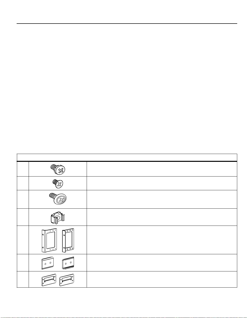
Hardware
4
8
20
2
2
Pan head screws for securing rail cleats to unit
Flat head screws for securing rack-mount or tie brackets to unit
Ornamental sc r e w s :
• 4 for securing unit to rack
• 16 for securing tie brackets in stack configuration
Cage nuts used in rack-m ount installation
Rack-mount brackets
2
2
SURT192RMXLBP2/SURT192RMXLBP2J User M anual 3
Rail cleats
Tie brackets for securing units in stack configuration
Page 5

Accessories
Install accessories prior to connecting power to the UPS.
Refer to the APC by Schneider Electric web site, www.apc.com for available accessories.
Specifications
Environmental Specifications
Temperature
Maximum
Operating 0° to 40° C (32° to 104° F) This unit is intended for indoor use
Storage -15° to 30° C (5° to 86° F)
charge UPS battery every six months
30° to 70° C (86° to 158° F)
charge UPS battery every three months
Operating 3,000 m (10,000 ft)
Elevation
Storage 15,000 m (50,000 ft)
Humidity
0 to 95% relative humidity,
non-condensing
Physical Specifications
Weight
Refer to the Safety Guide supplied with this unit for lifting guidelines.
Battery Pack with eight batte ry modules 181 kg (400 lbs)
without batte ry modules 44 kg (96 lbs)
each battery module 17 kg (38 lbs)
Maximum number of external battery packs (XLBPs)
10
Combined weights of UPS, battery pack and
all XLBPs installed in a rack must not exceed
rack weight limits.
only. Select a location sturdy
enough to handle the weight.
Do not operate unit where there is
excessive dust or temperature or
humidity are outside specified
limits.
Environmental factors impact
battery life. High temperatures, poor
utility power, and fre quen t, sho rt
duration discharges will shorten
battery life.
Dimensions
Battery Pack
SURT192RMXLBP2/ S UR T192RMXLBP2J User Manual 4
width
height
depth
482 mm (19 in) with rack-mount brackets
432 mm (17 in) witho ut rack-mount bracket s
263 mm (10 in)
739 mm (29 in) with PDU
720 mm (28 in) without PDU
Page 6

Installation
8x
8x
4x
2x
2x
Install rack-mount brackets
Four flat head screws
must be used to secure
each rack-mount bracket
to unit.
Install rail cleats
T w o pan head screws must
be used to secure each rail
cleat to unit.
Batteries must be removed from battery pack and XLBPs prior to installing units in
stack or rack-mount configuration. Refer to instructions on packaging for details on
removing batteries from battery pack and XLBPs.
Always place the UPS above the battery pack and XLBPs.
Stack configuration
Total stack configuration height must NOT exceed 18U. The UPS
and battery pack together equal 12U. Adding one XLBP creates an
18U configuration.
For detailed instructions on installing batteries, and battery doors,
refer to Rack-mount configuration in this manual.
Install tie brackets
Four ornamental screws ( sup pli ed i n b at tery pack package),
must be used to secure each tie bracket to the units.
Rack-mount configuration
Read the Safety Guide included in the package and refer to Physical Specifications in this manual
before installing the UPS.
su0182a
8x
Install rails in rack
For details on rail installation refer to instructions included in rail kit package.
SURT192RMXLBP2/SURT192RMXLBP2J User M anual 5
k
c
a
p
y
r
e
t
t
a
b
l
a
n
S
P
U
S
P
U
r
e
t
x
e
su0167a
4x
k
c
a
p
y
r
e
t
t
a
b
l
a
n
r
e
t
x
e
su0166a
Page 7

Install units in rack
su0183a
4x
4x
7 holes
7 holes
su0173a
su0186a
Secure UPS, battery pack and XLBP in rack using cage nuts and ornamental screws included in package.
Four ornamental screws and two cage nuts must be used to secure each unit.
A cage nut must be used in the top hole of each rack-mount bracket when securing the unit in the rack.
The bottom hole of each rack-mount bracket can be secured using an ornamental screw in the threaded
hole.
Install and connect battery modules
Connect all eight battery modules. Failure to do so may cause equipment damage.
Replace battery compartment doors. Tighten screws to secure battery compartment doors.
su0184a
Install bezels
There is a single latch on each side of the UPS bezel.
There are two latches on each side of the battery pack and
XLBP bezels.
SURT192RMXLBP2/ S UR T192RMXLBP2J User Manual 6
su0185a
Page 8

Connect UPS, Battery Pack and XLBP
su0189a
su0208a
Remove safety covers on
battery pack, and XLBP(s).
su0188a
su0190a
su0191a
UPS
Battery pack with
PDU installed
XLBP with no
PDU installed
Connect batteries as shown.
Rotate safety covers
Reinstall safety covers.
Ensure all battery
connectors used and
unused, have safety
covers installed.
su0187a
Connect ground wires as shown.
Ground
Ground
Ground
Thumb screw
Thumb screw
Prior to connecting the battery pack to the UPS the safety cove r
on the UPS battery connector must be adjusted.
• Loosen two th um b screws on safety cove r.
• Slide safety cover so that battery connectors are exposed.
• Securely engage battery connectors.
• Slide safety cover to lock battery connectors in place.
• Tighten thumb screws.
Units may vary in appearance from those depicted in this manual.
SURT192RMXLBP2/SURT192RMXLBP2J User M anual 7
Page 9

Operation
Battery LED
The battery LED is located on the front bezel of the XLBP. During normal operation the LED is not
illuminated.
On start-up the XLBP LED will illuminate and blink within the first minute. The LED should then
extinguish.
If the LED remains illuminated perform the following steps to extinguish the LED.
1. Allow unit to run for two continuous hours without removing or installing batteries.
2. Verify that display interface shows actual number of XLBPs connected.
3. Verify that display interface shows CHRG (battery charge), is greater the 95%.
4. Verify that display interface shows Load is greater than 5% x the number of external battery packs installed.
5. Verify that display interface shows Runtime is greater than 0 0hr3.3m.
6. Perform a sel f -test as described in Smart-UPS user manual.
If the LED remains illuminated after performing these steps, refer to the troubleshooting table below.
LED Activity Possible Cause Corrective Action after a Self-Test is
Performed
XLBP LED illuminates briefly
• On start up the XLBP LED will
i
lluminate and blink within the firs
minute.
• The XLBP is establishi ng
communication w i t h other
com
ponents of the syst em .
• The XLBP is conduc ti ng a normal
periodic self test
Normal operatio n No action is necessary.
t
XLBP LED remains illuminated
NOTE: Read the information and perform steps outlined in the list above prio r to perfor min g the acti on s listed in
this table.
XLBP LED is blinking slowly
(one blink per se cond).
XLBP LED is flashing rapidly
(three flashes per second).
The XLBP LED remains illuminated. A potential hardware fault exists. Contact APC by Schneider Electric, refer to
One or more battery modules are not
connected.
A communication fault exists, check
cable connection s.
• Check that all battery connections in the UPS/
XLBP configurati on a re secure.
• Replace battery modules.
• Check that all cable and battery con n ections
in the UPS/XLBP configuration are secure.
• Testing beyond the self-test may be required
Contact APC by Schnei der Electric. Refer to
Service in this manual.
Service in this manual.
.
XLBP LED does not illuminate
On start up the XLBP LED
does not illuminate
SURT192RMXLBP2/ S UR T192RMXLBP2J User Manual 8
Normal operation. No action is necessary.
Page 10

Battery module and pair identification
su0178a
The display interface will reference XLBP configuration in the following manner.
External Battery Pack
Negative BattPair 1 Positive BattPair 2
Module 1 Module 2 Module 3 Module 4
Negative BattPair 3 Positive BattPair 4
Module 5 Module 6 Module 7 Module 8
SURT192RMXLBP2/SURT192RMXLBP2J User M anual 9
Page 11

Maintenance, Transport, and Service
Be sure to deliver the spent battery(s) to a recycling facility or ship it to APC in the
replacement battery packing material.
Replace battery modules
This UPS has easy to replace, hot swappable battery modules. Replacement is a safe procedure, isolated
from electrical hazards. You may leave the UPS and connected equipment on during the replacement
procedure.
Once the batteries are disconnected the connected equipment is not protected from power outages.
Refer to the appropriate replacement battery user manual for battery module installation instructions. See
your dealer or contact APC by Schneider Electric at www.apc.com for information on replacement battery
modules.
Transport
1. Shut down and disconnect all connected equipment.
2. Disconnect the unit from utility power.
3. Disconnect all intern al and external batteries (if applicable).
4. Follow the shipping instructions outlined in the Service section of this manual.
SURT192RMXLBP2/ S UR T192RMXLBP2J User Manual 10
Page 12

Limited Factory Warranty
Schneider Electric IT Corporation (SEIT), warrants its products to be free from defects in materials and workmanship for a period of
two (2) years from the date of purch ase . The SEIT obl igation under this warranty is limited to repairing or replacing, at its own sole
option, any such defectiv e products. Repair or replaceme nt of a defective product or parts there o f doe s not ext end the original
warranty period.
This warranty applies only to the ori ginal purchaser who must have prope rly registered the product within 10 days of purchase.
Products may be registered onli ne at wa rra nty.apc.com.
SEIT shall not be liable under the warranty if its testing and examination disclose that the alleged defect in the product does not exist
or was caused by end user or any thir d person misuse, negligence, improper installation, testing, operati on or use of the product
contrary to SEIT recommen dat io ns or specifications. Further, SEIT shall not be liable for defects resul ti ng from: 1) unauthorized
attempts to repair or modify the product, 2) incorrect or inadequate electri ca l voltage or connection, 3) inappropriate on site
operation conditions, 4) Acts of God, 5) exposure to the elemen ts, or 6) th eft . In n o event shall SEIT have any liabilit y under this
warranty f or a n y product where the ser ial number has been al t ered, defaced, or removed.
EXCEPT AS SET FORTH ABOVE, THERE ARE NO WARRANTIES, EXPRESS OR IMPLIED, BY OPERATION OF
LAW OR OTHERWISE, APPLICABLE TO PRODUCTS SOLD, SERVICED OR FURNISHED UNDER THIS
AGREEMENT OR IN CONNECTION HEREWITH.
SEIT DISCLAIMS ALL IMPLIED WARRANTIES OF MERCHANTABILITY, SATISFACTION AND FITNESS FOR A
PARTICULAR PURPOSE.
SEIT EXPRESS WARRANTIES WILL NOT BE ENLARGED, DIMINISHED, OR AFFECTED BY AND NO
OBLIGATION OR LIABILITY WILL ARISE OUT OF, SEIT RENDERING OF TECHNICAL OR OTHER ADVICE OR
SERVICE IN CONNECTION WITH THE PRODUCTS.
THE FOREGOING WARRANTIES AND REMEDIES ARE EXCLUSIVE AND IN LIEU OF ALL OTHER
WARRANTIES AND REMEDIES. THE WARRANTIES SET FORTH ABOVE CONSTITUTE SEIT SOLE LIABILITY
AND PURCHASER EXCLUSIVE REMEDY FOR ANY BREACH OF SUCH WARRANTIES. SEIT WARRANTIES
EXTEND ONLY TO ORIGINAL PURCHASER AND ARE NOT EXTENDED TO ANY THIRD PARTIES.
IN NO EVENT SHALL SEIT, ITS OFFICERS, DIRECTORS, AFFILIATES OR EMPLOYEES BE LIABLE FOR ANY
FORM OF INDIRECT, SPECIAL, CONSEQUENTIAL OR PUNITIVE DAMAGES, ARISING OUT OF THE USE,
SERVICE OR INSTALLATION OF THE PRODUCTS, WHETHER SUCH DAMAGES ARISE IN CONTRACT OR
TORT, IRRESPECTIVE OF FAULT, NEGLIGENCE OR STRICT LIABILITY OR WHETHER SEIT HAS BEEN
ADVISED IN ADVANCE OF THE POSSIBILITY OF SUCH DAMAGES. SPECIFICALL Y, SEIT IS NOT LIABLE FOR
ANY COSTS, SUCH AS LOST PROFITS OR REVENUE, WHETHER DIRECT OR INDIRECT, LOSS OF EQUIPMENT ,
LOSS OF USE OF EQUIPMENT, LOSS OF SOFTWARE, LOSS OF DATA, COSTS OF SUBSTITUANTS, CLAIMS BY
THIRD PARTIES, OR OTHERWISE.
NOTHING IN THIS LIMITED WARRANTY SHALL SEEK TO EXCLUDE OR LIMIT SEIT LIABILITY FOR DEATH
OR PERSONAL INJURY RESUL TING FROM ITS NEGLIGENCE OR ITS FRAUDULENT MISREPRESENT ATION OF
TO THE EXTENT THAT IT CANNOT BE EXCLUDED OR LIMITED BY APPLICABLE LAW.
To obtain service under warranty you must obtain a Returned Material Authorization (RMA) number from customer support.
Customers with warranty claims issues may access the SEIT worldwide customer support network through the APC web site:
www.apc.com
obtain information for customer support in your region. Produc ts m ust be ret urned with transportation charges prepaid and must be
accompanied by a brief de scription of the problem encountered and proof of date an d place of purchase.
. Select your country from the coun try sele c ti on drop down menu. Open the Support ta b at the top of the w eb pag e to
SURT192RMXLBP2/SURT192RMXLBP2J User M anual 11
Page 13

Page 14

© 2014 APC by Schneider Electric. Smart-UPS and PowerChute are owned by Schneider Electric
Industries S.A.S. or their affiliated companies. All other trademarks are property of their respective
owners.
EN 990-2485C-002
07/2014
 Loading...