

Page 1
Page 2
Page 3
Page 4

Selection Guide
SmartX PIBCV Selection Options
There are three methods for selecting SmartX PIBCV valves
and Actuators:
1: Complete Method: Valve Assembly Selection
2. Custom Method: Valve Body and Actuator Field Assembly
3. Valve Only Method: Automatic Flow Limited Balance
1: Complete Method: Valve Assembly
Selection
To select a PIBCV valve assembly select the required flow
rate and actuator type. For example, to select a PIBCV valve
assembly with a flow rate of 1.5 GPM and a non-spring return
proportional actuator refer to Table 1. Valve Assemblies
½…1¼” With Female NPT End Connectors, Without PT Ports
on page 6.
Select the 1.5 GPM flow rate with the left column of the table.
Select the actuator from the top row of the table.
The intersecting valve assembly part number from the left
column and top row selections shows VP228E-15SN-L15-S101
which includes the set 1.5 GPM flow rate, installed actuator,
female NPT end connectors, and metal tag with flow rate.
Specifications for the selected valve body actuators are
in Table 3. Specification ½…1¼” Valve Body Actuators on
page 7 and for the valve body in Table 12. Specification
Threaded Version, ½…2" on page 11.
2. Custom Method: Valve Body and
Actuator Field Assembly
Select the individual parts then set the flow rate and field
assemble a valve assembly.
Table 12. Specification Threaded Version, ½…2" on page 11
shows the valve body specifications and Table 23. ½…2” Valve
Flow Ranges (Q
2½”…10” Flanged Valve Flow Ranges (Q
19, show the valve body flow rate ranges.
For example, to select a valve body that can be used in the
flow rate range of 1 to 2 GPM, from Table 23. ½…2” Valve
Flow Ranges (Q
15BQSNT valve body that does not include PT ports, or select
the VP-228E-15BSQ valve body if PT Ports are required.
Other larger valves could also provide the 1 to 2 GPM flow
rates, but the VP-228E-15BQSNT was selected because it will
be using a higher percentage of its flow range (in general, best
accuracy is achieved when a higher percentage of flow rate is
used).
The ½” to 2” PIBCV valves use convenient valve body tail
pieces for connection to the piping system.
to Qnom) on page 18, and Table 24.
min
min
to Q
) on page 18, select the VP-228E-
nom
min
to Q
nom
) on page
From Table 17. Selection: ½"…2" Valve Body Tail Pieces on
page 14, select the desired ½” tail piece – part number
9112108015 for Female NPT, 9112110015 for Male NPT, or
9112109015 for Sweat. Each tail piece part number includes
two tail pieces.
Table 3. Specification ½…1¼” Valve Body Actuators on page
7 shows the compatible actuators.
Select the MP131-24T for two position control, the MP131-24F
for floating control, the MP-131-24MP for proportional control,
the MP300-SRU for spring return open universal control, or the
MP300-SRD for spring return close universal control. Universal
control actuators provide both proportional and floating input
functionality. The valve body flow can easily be set before the
actuator is installed as shown in the PIBCV Flow Setting on
page 5.
3. Valve Body Only: Automatic Flow
Limited Balance Example
PIBCV valves can be used without actuators to limit the circuit
flow to an adjustable flow rate.
Table 12. Specification Threaded Version, ½…2" on page
11 shows the valve body specifications and Table 23. ½…2”
Valve Flow Ranges (Q
2½”…10” Flanged Valve Flow Ranges (Q
19 show the valve body flow rate ranges.
For example, to select a valve body that can be used in the
flow rate range of 2 to 5 GPM from Table 23 select the VP229E15BQHNT valve body part number. The ½” to 2” PIBCV valves
use convenient valve body tail pieces for connection to the
piping system.
From Table 17. Selection: ½"…2" Valve Body Tail Pieces on
page 14, select the desired ½” tail piece: part number
9112108015 for Female NPT, 9112110015 for Male NPT, or
9112109015 for Sweat. Each tail piece part number includes
two tail pieces.
The 1½" and larger sized valves require a stem lock when
used without an actuator as shown in Table 11. Application:
Operation of PIBCV Valve Body Without Actuator on page 10
(which also shows application information for the valve bodies
without actuators). The valve body flow can easily be set as
shown in the PIBCV Flow Setting Section.
min
to Q
) on page 18 and Table 24.
nom
min
to Q
) on page
nom
Januar y, 2019 tc © 2019 Schneider Elec tric. A ll right s reser ved. All trademarks ar e owned by S chneider Electr ic Indus tries S AS or its a ffil iated com panies .
Document Number: F-27947-7
Page 5
Page 6
Selection Guide
Valve Assembly and Suitable Actuators
Table 1. Valve Assemblies ½…1¼” With Female NPT End Connectors, Without PT Ports
Flow
Rate
a
(GPM)
0.5 1/2 VP228E-10LN-L05-A101 VP228E-10LN-L05-F101 VP228E-10LN-L05-S101 VP228E-10LN-L05-U201 VP228E-10LN-L05-U301
1.0 1/2 VP228E-15LN-L10-A101 VP228E-15LN-L10-F101 VP228E-15LN-L10-S101 VP228E-15LN-L10-U201 VP228E-15LN-L10-U301
1.5 1/2 VP228E-15SN-L15-A101 VP228E-15SN-L15-F101 VP228E-15SN-L15-S101 VP228E-15SN-L15-U201 VP228E-15SN-L15-U301
2.0 1/2 VP228E-15SN-L20-A101 VP228E-15SN-L20-F101 VP228E-15SN-L20-S101 VP228E-15SN-L20-U201 VP228E-15SN-L20-U301
2.5 1/2 VP229E-15HN-L25-A101 VP229E-15HN-L25-F101 VP229E-15HN-L25-S101 VP229E-15HN-L25-U201 VP229E-15HN-L25-U301
3.0 1/2 VP229E-15HN-L30-A101 VP229E-15HN-L30-F101 VP229E-15HN-L30-S101 VP229E-15HN-L30-U201 VP229E-15HN-L30-U301
3.5 1/2 VP229E-15HN-L35-A101 VP229E-15HN-L35-F101 VP229E-15HN-L35-S101 VP229E-15HN-L35-U201 VP229E-15HN-L35-U301
4.0 1/2 VP229E-15HN-L40-A101 VP229E-15HN-L40-F101 VP229E-15HN-L40-S101 VP229E-15HN-L40-U201 VP229E-15HN-L40-U301
4.0 3/4 VP228E-20SN-L40-A101 VP228E-20SN-L40-F101 VP228E-20SN-L40-S101 VP228E-20SN-L40-U201 VP228E-20SN-L40-U301
4.5 1/2 VP229E-15HN-L45-A101 VP229E-15HN-L45-F101 VP229E-15HN-L45-S101 VP229E-15HN-L45-U201 VP229E-15HN-L45-U301
5.0 1/2 VP229E-15HN-L50-A101 VP229E-15HN-L50-F101 VP229E-15HN-L50-S101 VP229E-15HN-L50-U201 VP229E-15HN-L50-U301
5.5 3/4 VP229E-20HN-L55-A101 VP229E-20HN-L55-F101 VP229E-20HN-L55-S101 VP229E-20HN-L55-U201 VP229E-20HN-L55-U301
6.0 3/4 VP229E-20HN-L60-A101 VP229E-20HN-L60-F101 VP229E-20HN-L60-S101 VP229E-20HN-L60-U201 VP229E-20HN-L60-U301
6.5 3/4 VP229E-20HN-L65-A101 VP229E-20HN-L65-F101 VP229E-20HN-L65-S101 VP229E-20HN-L65-U201 VP229E-20HN-L65-U301
7.0 3/4 VP229E-20HN-L70-A101 VP229E-20HN-L70-F101 VP229E-20HN-L70-S101 VP229E-20HN-L70-U201 VP229E-20HN-L70-U301
7.5 3/4 VP229E-20HN-L75-A101 VP229E-20HN-L75-F101 VP229E-20HN-L75-S101 VP229E-20HN-L75-U201 VP229E-20HN-L75-U301
7.5 1 VP229E-25SN-L75-A101 VP229E-25SN-L75-F101 VP229E-25SN-L75-S101 VP229E-25SN-L75-U201 VP229E-25SN-L75-U301
8 1 VP229E-25HN-L80-A101 VP229E-25HN-L80-F101 VP229E-25HN-L80-S101 VP229E-25HN-L80-U201 VP229E-25HN-L80-U301
8.5 1 VP229E-25HN-L85-A101 VP229E-25HN-L85-F101 VP229E-25HN-L85-S101 VP229E-25HN-L85-U201 VP229E-25HN-L85-U301
9.0 1 VP229E-25HN-L90-A101 VP229E-25HN-L90-F101 VP229E-25HN-L90-S101 VP229E-25HN-L90-U201 VP229E-25HN-L90-U301
9.5 1 VP229E-25HN-L95-A101 VP229E-25HN-L95-F101 VP229E-25HN-L95-S101 VP229E-25HN-L95-U201 VP229E-25HN-L95-U301
10 1 VP229E-25HN-010-A101 VP229E-25HN-010-F101 VP229E-25HN-010-S101 VP229E-25HN-010-U201 VP229E-25HN-010-U301
11 1 VP229E-25HN-011-A101 VP229E-25HN-011-F101 VP229E-25HN-011-S101 VP229E-25HN-011-U201 VP229E-25HN-011-U301
12 1 VP229E-25HN-012-A101 VP229E-25HN-012-F101 VP229E-25HN-012-S101 VP229E-25HN-012-U201 VP229E-25HN-012-U301
13 1¼ VP229E-32SN-013-A101 VP229E-32SN-013-F101 VP229E-32SN-013-S101 VP229E-32SN-013-U201 VP229E-32SN-013-U301
14 1¼ VP229E-32SN-014-A101 VP229E-32SN-014-F101 VP229E-32SN-014-S101 VP229E-32SN-014-U201 VP229E-32SN-014-U301
15 1¼ VP229E-32HN-015-A101 VP229E-32HN-015-F101 VP229E-32HN-015-S101 VP229E-32HN-015-U201 VP229E-32HN-015-U301
16 1¼ VP229E-32HN-016-A101 VP229E-32HN-016-F101 VP229E-32HN-016-S101 VP229E-32HN-016-U201 VP229E-32HN-016-U301
17 1¼ VP229E-32HN-017-A101 VP229E-32HN-017-F101 VP229E-32HN-017-S101 VP229E-32HN-017-U201 VP229E-32HN-017-U301
24 Vac Two Position with Auxiliary
Valve
Switch (MP131-24T)
Size
(inch)
24 Vac Three Wire Floating
with Auxiliary Switch
(MP131-24F)
24 Vac Proportional with
Position Output Signal
(MP131-24MP)
24 Vac Proportional/Floating with
Position Output Signal Spring Return
Open (MP300-SRU)
24 Vac Proportional/Floating with
Position Output Spring Return Closed
(MP300-SRD)
a. Factory set. Complete flow ranges shown in tables for 1/2…2" on page 11 and page 18.
Januar y, 2019 tc © 2019 Schneider Elec tric. A ll right s reser ved. All trademarks ar e owned by S chneider Electr ic Indus tries S AS or its a ffil iated com panies .
Document Number: F-27947-7
Page 7

Table 2. Valve Assemblies ½…1¼” With Female NPT End Connectors, With PT Ports
24 Vac Two Position with Auxiliary
Switch (MP131-24T)
Flow
Valve
Rate
Size
a
(GPM)
(inch)
0.5 1/2 VP228E-10L-L05-A101 VP228E-10L-L05-F101 VP228E-10L-L05-S101 VP228E-10L-L05-U201 VP228E-10L-L05-U301
1.0 1/2 VP228E-15L-L10-A101 VP228E-15L-L10-F101 VP228E-15L-L10-S101 VP228E-15L-L10-U201 VP228E-15L-L10-U301
1.5 1/2 VP228E-15S-L15-A101 VP228E-15S-L15-F101 VP228E-15S-L15-S101 VP228E-15S-L15-U201 VP228E-15S-L15-U301
2.0 1/2 VP228E-15S-L20-A101 VP228E-15S-L20-F101 VP228E-15S-L20-S101 VP228E-15S-L20-U201 VP228E-15S-L20-U301
4.0 3/4 VP228E-20S-L40-A101 VP228E-20S-L40-F101 VP228E-20S-L40-S101 VP228E-20S-L40-U201 VP228E-20S-L40-U301
7.5 1 VP229E-25S-L75-A101 VP229E-25S-L75-F101 VP229E-25S-L75-S101 VP229E-25S-L75-U201 VP229E-25S-L75-U301
14 1¼ VP229E-32S-014-A101 VP229E-32S-014-F101 VP229E-32S-014-S101 VP229E-32S-014-U201 VP229E-32S-014-U301
a. Factory set. Complete flow ranges shown in tables for 1/2…2" on page 11 and page 18.
24 Vac Three Wire Floating
with Auxiliary Switch
(MP131-24F)
24 Vac Proportional with
Position Output Signal
(MP131-24MP)
24 Vac Proportional/Floating Spring
Return Open (MP300-SRU)
24 Vac Proportional/Floating Spring
Return Closed (MP300-SRD)
Selection Guide
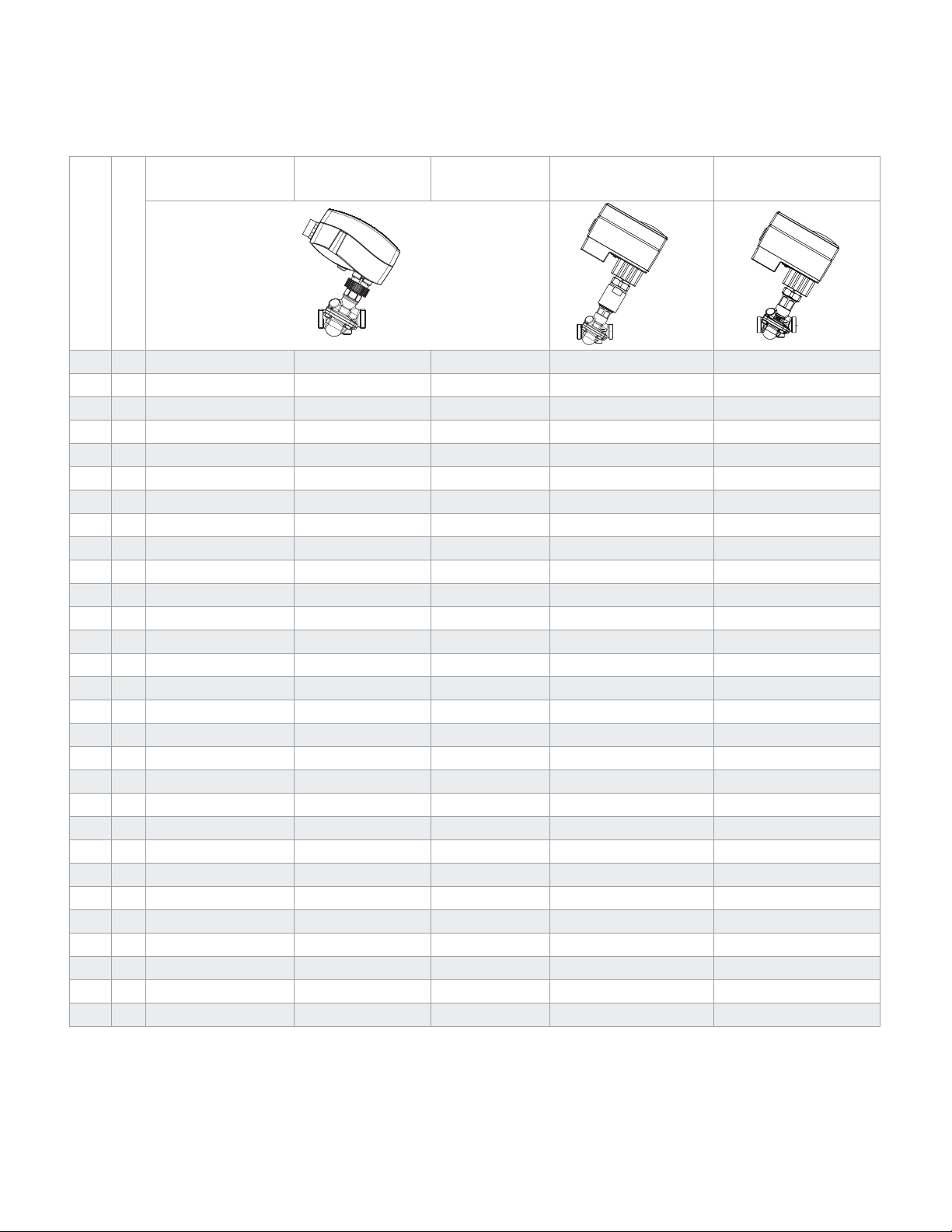
Table 3. Specification ½…1¼” Valve Body Actuators
1/2” to 1¼” Valve Body
Actuator Part Number
(actuator code)
Input Signal
Electrical Connection Screw terminal with conduit connector
Position Feedback Output
Signal
Spring Return – – – Open Valve Close Valve
Auxilary Switch Yes Ye s – – –
Other Features – –
Linear/Equal% Valve Flow
Curve Selection
Actuator Speed s/mm
60 Hz (50 Hz)
Power Consumption 1 VA 1.5 VA 9 VA
Actuator Weight (lb.) .9 2.0 1.3
Operating Temperature
Limits °F (°C)
Regulatory Compliance cULus according to UL 60730-1A/-2-14 and CAN/CSA E60730-1/-2-14 and CE according to EN 60730-1/-2-14 per EMC [2014/30/EU] and LVD [2014/35/EU]
Specification Data Sheet F-27961 F-27962
Installation Data sheet F-27938 F-27949 F-27948 F-27954
All actuators are 24 Vac. 50/60 HZ with removable conduit connector plate and wiring terminal block, manual override
MP131-24T
(A101)
Two Position, 3 Wire with
selectable input jumper
signal action selection
– – 0…10 Vdc 0…10 Vdc, 2…10 Vdc
– – Yes Yes
MP131-24F
(F101)
Three Wire Floating
20 (24) 11.7 (14)
MP131-24MP
(S101)
Proportional, 0…10 Vdc, 2…10
Vdc, 4…20 mA, sequencing
with selectable input signal ac-
tion, DIP switch selectable
Weekly anti blocking selection,
auto calibration, LED indication
32…131 (0…55)
MP300-SRU
(U201)
Proportional, 0…10 Vdc, 2…10 Vdc, 4…20 mA, sequencing with selectable
input signal action and Floating, DIP switch selectable
Valve stroke length selection, LED indication
MP300-SRD
(U301)
© 2019 Schneider Elec tric. A ll right s reser ved. All trademarks ar e owned by S chneider Electr ic Indus tries S AS or its a ffil iated com panies . Januar y, 2019 tc
Docume nt Numbe r: F-27947-7
Page 8

Selection Guide
Table 4. Valve Assemblies 1½”, 2” With Female NPT End Connectors, With PT Ports
24 Vac Proportional with Position Output Signal
(MP500C)
24 Vac Proportional/Floating with Position Output
Signal Spring Return Open
(MP500C-SRU)
24 Vac Proportional/Floating with Position Output
Spring Return Closed
(MP500C-SRD)
Flow Rate
(GPM)
18 1½ VP220E-40S-018-U131 VP220E-40S-018-U231 VP220E-40S-018-U331
19 1½ VP220E-40S-019-U131 VP220E-40S-019-U231 VP220E-40S-019-U331
20 1½ VP220E-40S-020-U131 VP220E-40S-020-U231 VP220E-40S-020-U331
22 1½ VP220E-40S-022-U131 VP220E-40S-022-U231 VP220E-40S-022-U331
24 1½ VP220E-40S-024-U131 VP220E-40S-024-U231 VP220E-40S-024-U331
26 1½ VP220E-40S-026-U131 VP220E-40S-026-U231 VP220E-40S-026-U331
28 1½ VP220E-40S-028-U131 VP220E-40S-028-U231 VP220E-40S-028-U331
30 1½ VP220E-40S-030-U131 VP220E-40S-030-U231 VP220E-40S-030-U331
32 1½ VP220E-40S-032-U131 VP220E-40S-032-U231 VP220E-40S-032-U331
34 2 VP220E-50S-034-U131 VP220E-50S-034-U231 VP220E-50S-034-U331
36 2 VP220E-50S-036-U131 VP220E-50S-036-U231 VP220E-50S-036-U331
38 2 VP220E-50S-038-U131 VP220E-50S-038-U231 VP220E-50S-038-U331
40 2 VP220E-50S-040-U131 VP220E-50S-040-U231 VP220E-50S-040-U331
44 2 VP220E-50S-044-U131 VP220E-50S-044-U231 VP220E-50S-044-U331
48 2 VP220E-50S-048-U131 VP220E-50S-048-U231 VP220E-50S-048-U331
52 2 VP220E-50S-052-U131 VP220E-50S-052-U231 VP220E-50S-052-U331
a. Factory set. Complete flow ranges shown in tables for 1/2…2" on page 11 and page 18.
Valve
Size
a
(inch)
Table 5. Valve Assemblies 2½"…4” with ANSI Standard B16.1 Flanges, With PT Ports
24 Vac Proportional with Position Output Signal (MP500C)
Flow Rate
(GPM)
56 2½ VP220A-65S-056-U131 VP220A-65S-056-U231 VP220A-65S-056-U331
60 2½ VP220A-65S-060-U131 VP220A-65S-060-U231 VP220A-65S-060-U331
65 2½ VP220A-65S-065-U131 VP220A-65S-065-U231 VP220A-65S-065-U331
70 2½ VP220A-65S-070-U131 VP220A-65S-070-U231 VP220A-65S-070-U331
75 2½ VP220A-65S-075-U131 VP220A-65S-075-U231 VP220A-65S-075-U331
80 2½ VP220A-65S-080-U131 VP220A-65S-080-U231 VP220A-65S-080-U331
90 3 VP220A-80S-090-U131 VP220A-80S-090-U231 VP220A-80S-090-U331
100 3 VP220A-80S-100-U131 VP220A-80S-100-U231 VP220A-80S-100-U331
165 (min. 66) 4 VP220A-100S-165-U131 VP220A-100S-165-U231 VP220A-100S-165-U331
a. Factory set. Complete flow ranges shown in tables for 2½"…4" on page 12 and page 19.
Januar y, 2019 tc © 2019 Schneider Elec tric. A ll right s reser ved. All trademarks ar e owned by S chneider Electr ic Indus tries S AS or its a ffil iated com panies .
Document Number: F-27947-7
Valve
Size
a
(inch)
24 Vac Proportional/Floating with Position Output
Signal Spring Return Open
(MP500C-SRU)
24 Vac Proportional/Floating with Position
Output Signal Spring Return Closed (MP500C-
SRD)
Page 9

Table 6. Specification 1½”…4” Valve Body Actuators
1½”…4” Valve Body Actuator Part
Number (actuator code)
Input Signal Proportional, 0…10 Vdc, 2…10 Vdc, 4…20 mA, sequencing with selectable input signal action and Floating, DIP switch selectable
Electrical Connection Screw terminal with conduit connector
Position Feedback Output Signal 2…10 Vdc 2…10 Vdc, 0…5 Vdc
Spring Return – Open Valve Close Valve
Auxilary Switch Optional Module
Other Features
Linear/Equal% Valve Flow Curve Selection Ye s Yes
Actuator Speed Full Stroke
60 Hz (50 Hz)
Power Consumption Running 15 VA, Transformer Sizing 50 VA Running 30 VA, Transformer Sizing 50 VA
Operating Temperature Limits °F (°C) 14…122 (-10…50)
Actuator Weight (lb.) 4.0 6.0
Regulatory Compliance
Specification Data Sheet F-27944 F-27945
Installation Data sheet F-27942 F-27943
All actuators are 24 Vac. 50/60 HZ with conduit connector holes and wiring terminal block, manual override
Auto calibration, field selectable floating input
signal travel time, powered manual override
Underwriters Laboratory (E9429) compliance as Temperature Indicating & Regulatory Equipment cULus LISTED per UL873 and Canadian
Standard C22.2 No. 24. European Community compliance per EMC directive (2014/30/EU) and LVD directive (2014/35/EU). Australian/New
Zealand community RCM mark.
MP500C
(U131)
Proportional 15 (15)
Floating 60 or 300 (60 or 300)
MP500C-SRU
(U231)
Auto calibration, field selectable floating input signal travel time
Floating 60 or 300 (60 or 300) Spring Return 13 (13)
Proportional 15 (15)
MP500C-SRD
(U331)
Table 7. Valve Assemblies 5” and 6” With PT Ports with ANSI Standard B16.1 Flanges
24 Vac Proportional with Position Output
Signal (MP2000-NSR)
24 Vac Proportional/Floating with Position
Output Signal Spring Return Open
(MP2000-SRU)
24 Vac Proportional/Floating with
Position Output Spring Return Closed
(MP2000-SRD)
Selection Guide
Flow Rate
(GPM)
395 (min. 158) 5 VP220A-125S-395-U161 VP220A-125S-395-U261 VP220A-125S-395-U361
485 (min. 194) 5 VP220A-125H-485-U161 VP220A-125H-485-U261 VP220A-125H-485-U361
640 (min. 256) 6 VP220A-150S-640-U161 VP220A-150S-640-U261 VP220A-150S-640-U361
830 (min. 332) 6 VP220A-150H-830-U161 VP220A-150H-830-U261 VP220A-150H-830-U361
a. Factory set. Complete flow ranges shown in tables for 5"…6" on page 12 and page 19.
Valve
Size
a
(inch)
Table 8. Specification 5”and 6” Valve Body Actuators
5” and 6” Valve Body Actuator Part
Number (actuator code)
Input Signal Proportional, 0…10 Vdc, 2…10 Vdc, 0…20 mA, 4…20 mA, with selectable input signal action and Floating, DIP swtich selectable
Electrical Connection Screw terminal with conduit connector
Position Feedback Output Signal 0…10 Vdc, 2…10 Vdc, 0…20 mA, 4…20 mA
Spring Return – Open Valve Close Valve
Auxilary Switch Yes
Other Features
Linear/Equal% Valve Flow Curve Selection Yes
Actuator Speed s/mm 60 Hz (50 Hz) 3 or 6 (3 or 6) 4 or 6 (4 or 6)
Power Consumption 15.0 VA
Operating Temperature Limits °F (°C) 32…131 (0…55)
Actuator Weight (lb.) 13.8 18.96
Regulatory Compliance
Specification Data Sheet F-27976 F-27969
Installation Data sheet F-27956
a. When used with a proportional input signal. All actuators are 24 Vac. 50/60 HZ with conduit connector holes and wiring terminal block, manual override
© 2019 Schneider Elec tric. A ll right s reser ved. All trademarks ar e owned by S chneider Electr ic Indus tries S AS or its a ffil iated com panies . Januar y, 2019 tc
Docume nt Numbe r: F-27947-7
cULus according to UL 60730-1A/-2-14 and CAN/CSA E60730-1/-2-14 and CE according to EN 60730-1/-2-14 per EMC [2014/30/EU] and LVD [2014/35/EU]
MP2000-NSR (U161) MP2000-SRU (U261) MP2000-SRD (U361)
a
configurable position outpout signals, selectable speed, adjustable equal percentage flow curve
Auto calibration, 3-color LED indication, powered manual override,
Page 10

Selection Guide
Table 9. Valve Assembly 8” and 10” With PT Ports
Flow Rate
(GPM)
880 (min. 352) 8 VP222A-200S-880-U181
1188 (min. 475) 8 VP222A-200H-1188-U181
1320 (min. 528) 10 VP222A-250S-1320-U181
1630 (min. 652) 10 VP222A-250H-1630-U181
* Factory set. Complete flow ranges are shown in tables for 8" and 10" on page
12 and page 19.
* Valve Size
(inch)
24 Vac Proportional with Position Output Signal
(MP4000)
Table 10. Specification 8” and 10” Valve Body Actuators
8" and 10" Valve Body Actuator Part Number (actuator code) MP4000 (U181)
Input Signal Proportional, 0…10 Vdc, 2…10 Vdc, 0…20 mA, 4…20 mA, with selectable input signal action and Floating, DIP swtich selectable
Electrical Connection Screw terminal with conduit connector
Position Feedback Output Signal 0…10 Vdc, 2…10 Vdc, 0…20 mA, 4…20 mA
Spring Return –
Auxilary Switch Yes
Other Features Auto calibration, LED indication, powered manual override, adjustable speed
Linear/Equal% Valve Flow Curve Selection Yes
Actuator Speed s/mm 60Hz (50 Hz) 3 or 6 (3 or 6)
Power Consumption 15 VA
Operating Temperature Limits °F (°C) 32…131 (0…55)
Actuator Weight (lb.) 16.53
Regulatory Compliance cULus according to UL 60730-1A/-2-14 and CAN/CSA E60730-1/-2-14 and CE according to EN 60730-1/-2-14 per EMC [2014/30/
Specification Data Sheet F-27971
Installation Data sheet F-27958
a. When used with a proportional input signal.
All actuators are 24 Vac. 50/60 HZ with conduit connector holes and wiring terminal block, manual override.
EU] and LVD [2014/35/EU]
a
Table 11. Application: Operation of PIBCV Valve Body Without Actuator
Operation of the PIBCV valve body without an actuator for an automatic flow limiting balancing application.
PIBCV Valve
Size
1/2”…1-1/4”
1-1/2”, 2” VP220E-xxxxx
2-1/2”…4” VP220A-xxxxx
5”…6” VP221A-xxxxxx 9114071000 (not included with valve body)
8”…10” VP222A-xxxxx 9114072000 (not included with valve body)
The 9114070000, 9114071000, and 9114072000 Valve Stem Locks are secured to the valve body with a 10 mm allen wrench.
See Table 15. Assembly Valve Body Configurations on page 13 for a listing of all PIBCV valve body part numbers.
Januar y, 2019 tc © 2019 Schneider Elec tric. A ll right s reser ved. All trademarks ar e owned by S chneider Electr ic Indus tries S AS or its a ffil iated com panies .
Document Number: F-27947-7
Valve Body Series Valve Stem Lock Part Number Recommended Installation and Valve Shut Off Capability
VP228E-xxxxxxx, VP229E-
xxxxxxx
Use black cap provided with VP228E-xxxxxxx or
VP229E-xxxxxxx valve body
9114070000 (not included with valve body)
Install valve in the supply water pipe for best shutoff valve performance. To shutoff
valve tighten black cap (max. close off pressure is 14.5 psi). To shut off against a
Install valve in either the supply or return water pipe. To shutof f valve tighten bottom
Install valve in either the supply or return water pipe. To shutof f valve tighten bottom
higher differential pressure set the valve flow to 0%.
knob (max. close off pressure is 232 psi)
insert with a 8 mm allen wrench (max. close off pressure is 232 psi)
No shut off knob, set the valve to a 0% flow setting to shutoff flow
Page 11

Page 12

Page 13

Table 15. Assembly Valve Body Configurations
Pipe Size
(in.)
1/2 VP228E-10LN- VP228E-10BQLNT Threaded 911 2108 010
1/2 VP228E-10L- VP228E-10BQL Threaded 911 2108 010 Ye s
1/2 VP228E-15LN- VP228E-15BQLNT Threaded 911 2108 015
1/2 VP228E-15L- VP228E-15BQL Threaded 911 2108 015 Ye s
1/2 VP228E-15SN- VP228E-15BQSNT Threaded 911 2108 015
1/2 VP228E-15S- VP228E-15BQS Threaded 911 2108 015 Ye s
1/2 VP229E-15HN- VP229E-15BQHNT Threaded 911 2108 015
3/4 VP228E-20SN- VP228E-20BQSNT Threaded 911 2108 020
3/4 VP228E-20S- VP228E-20BQS Threaded 911 2108 020 Ye s
3/4 VP229E-20HN- VP229E-20BQHNT Threaded 911 2108 020
1 VP229E-25SN- VP229E-25BQSNT Threaded 911 2108 025
1 VP229E-25S- VP229E-25BQS Threaded 911 2108 025 Ye s
1 VP229E-25HN- VP229E-25BQHNT Threaded 911 2108 025
1-1/4 VP229E-32SN- VP229E-32BQSNT Threaded 911 2108 032
1-1/4 VP229E-32S- VP229E-32BQS Threaded 911 2108 032 Ye s
1-1/4 VP229E-32HN- VP229E-32BQHNT Threaded 911 2108 032
1-1/2 VP220E-40S- VP220E-40CQS Threaded 911 2108 040 Ye s
2 VP220E-50S- VP220E-50CQS Threaded 911 2108 050 Yes
2-1/2 VP220A-65S- VP220A-65CQS Flanged Yes
3 VP220A-80S- VP220A-80CQS Flanged Yes
4 VP220A-100S- VP220A-100CQS Flanged Yes
5 VP220A-125S- VP221A-125CQS Flanged Yes
5 VP220A-125H- VP221A-125CQH Flanged Yes
6 VP220A-150S- VP221A-150CQS Flanged Yes
6 VP220A-150H- VP221A-150CQH Flanged Yes
8 VP222A-200S- VP222A-200CQS Flanged Yes
8 VP222A-200H- VP222A-200CQH Flanged Yes
10 VP222A-250S- VP222A-250CQS Flanged Ye s
10 VP222A-250H- VP222A-250CQH Flanged Ye s
Valve Assembly
Part Number Series
Complete Valve Body
Part Number
Valve Type
Female NPT End Connectors (included with all 1/2”
through 2” Valve Actuator Assemblies)
PT Ports
Selection Guide
Installation Data
Sheet
F-27937
F-27934
F-27939
© 2019 Schneider Elec tric. A ll right s reser ved. All trademarks ar e owned by S chneider Electr ic Indus tries S AS or its a ffil iated com panies . Januar y, 2019 tc
Docume nt Numbe r: F-27947-7
Page 14

Page 15

Page 16

Page 17

Page 18

Selection Guide
Table 23. ½…2” Valve Flow Ranges (Q
Flow Rate
(GPM)
Without PT Ports
With PT Ports
0.5 1 1 1
1.0 1 1 1 1
1.5 1 1 1 1 1
2.0 1 1 1 1 1
2.5 1 1 1 1 1
3.0 1 1 1 1 1 1
3.5 1 1 1 1 1 1 1
4.0 1 1 1 1 1 1 1
4.5 1 (1) 1 1 1 1 1
5.0 1 1 1 1 1 1
5.5 (1) 1 1 1 1 1
6.0 1 1 1 1 1
6.5 1 1 1 1 1
7.0 1 1 1 1 1
7.5 1 1 1 1 1
8.0 (1) (1) 1 1 1
8.5 1 1 1
9.0 1 1 1
9.5 1 1 1
10 1 1 1
11 1 1 1
12 1 1 1
13 (1) 1 1 1
14 1 1 1
15 (1) 1 1
16 1 1
17 1 1
18 (1) 1
19 (1) 1
20 1
21 1
22 1
23 1
24 1
25 1
26 1
27 1
28 1
29 1
30 1
31 1
32 1
33 1
34
35
36
37
38
39
40
44
48
52
55
VP228E-
10BQLNT
VP228E-
10BQL
1/2” 3/4” 1” 1¼” 1½” 2"
VP228E-
15BQLNT
VP228E-
15BQL
VP228E-
15BQSNT
VP228E-
15BQS
min
VP229E-
15BQHNT
-
to Q
VP228E-
20BQSNT
VP228E-
20BQS
nom
)
VP229E-
20BQHNT
-
VP229E-
25BQSNT
VP229E-
25BQS
VP229E-
25BQHNT
-
VP229E-
32BQSNT
VP229E-
32BQS
VP229E-
32BQHNT
-
- -
VP220E-
40CQS
VP220E-
50CQS
1
1
1
1
1
1
1
1
1
1
1
1
1
1
1
1
1
1
1
1
1
1
1
(Q
setting)
high
Januar y, 2019 tc © 2019 Schneider Elec tric. A ll right s reser ved. All trademarks ar e owned by S chneider Electr ic Indus tries S AS or its a ffil iated com panies .
Document Number: F-27947-7
Page 19

Selection Guide
Table 24. 2½”…10” Flanged Valve Flow Ranges (Q
Size 2½” 3” 4” 5” 6” 8” 10”
Flow Rate (GPM)
35 34
40 1
45 1
50 1 48
55 1 1
60 1 1
65 1 1
70 1 1 66
75 1 1 1
80 1 1 1
85 85 1 1
90 1 1
95 1 1
100 1 1
120 120 1
140 1
160 165 158
180 1
200 1 194
250 1 1 256
300 1 1 1
350 1 1 1 332 352
400 395 1 1 1 1
450 485 1 1 1 475
500 1 1 1 1 528
550 1 1 1 1 1
600 640 1 1 1 1
650 1 1
700 1 1 1 1 1
750 1 1 1 1 1
800 830 1 1 1 1
850 880 1 1 1
900 1 1 1
950 1 1 1
1000 1 1 1
1100 1188 1 1
1200 1 1
1300 1320 1
1400 1
1500 1
1600 1630
1700
VP220A-
65CQS
VP220A-
80CQS
VP220A100CQS
VP221A125CQS
VP221A125CQH
min
VP221A150CQS
to Q
nom
VP221A150CQH
)
VP222A200CQS
VP222A200CQH
1 1 652
All flanged valves come standard with the PT ports
VP222A250CQS
VP222A250CQH
Specification Submittal Text
SmartX PIBCV has the following specifications:
1. NPS 2 and Smaller: PN 16, stainless steel components.
2. NPS 2-1/2 through 10: Class 125 cast iron body per ASME B16.1-2010,
Material class B per ASTM A 126-04 (2014), stainless steel components.
3. Accuracy NPS ¾ and Smaller: The control valves shall accurately control the
flow from 0 to 100% rated flow with a differential pressure range of 2.32 to
58 psi for low and standard flow units, 5 to 58 psi for high flow units within
5% of set flow value.
4. Accuracy NPS 1 through 1-1/4: The control valves shall accurately control
the flow from 0 to 100% rated flow with a differential pressure range of 2.9 to
58 psi for standard flow units, 5 to 58 psi for high flow units within 5% of set
flow value.
the flow from 0 to 100% rated flow with a differential pressure range of 4.35
to 58 psi within 5% of set flow value.
6. Accuracy NPS 5 through 10: The control valves shall accurately control the
flow from 0 to 100% rated flow with a differential pressure range of 5.8 to 58
psi for standard flow units, 8.7 to 58 psi for high flow units within 5% of set
flow value.
7. Flow Characteristics: Linear Control, selectable to equal percentage at the
proportional valve actuator.
8. Field adjustable flow by means of a percentage of rated valve flow.
9. Position feedback output signal integrated into all proportional actuators.
10. 100% authority with modulating below 1% regardless of flow settings.
11. No cartridges requiring replacement or maintenance.
12. Close off ratings shall be 232 psi for all valve sizes.
5. Accuracy NPS 1-1/2 through 4: The control valves shall accurately control
© 2019 Schneider Elec tric. A ll right s reser ved. All trademarks ar e owned by S chneider Electr ic Indus tries S AS or its a ffil iated com panies . Januar y, 2019 tc
Docume nt Numbe r: F-27947-7
Page 20

Selection Guide
Januar y, 2019 tc © 2019 Schneider Elec tric. A ll right s reser ved. All trademarks ar e owned by S chneider Electr ic Indus tries S AS or its a ffil iated com panies .
Document Number: F-27947-7
 Loading...