

ModiconTM3
EIO0000003125 06/2020
Modicon TM3
Digital I/O Modules
Hardware Guide
06/2020
EIO0000003125.03
www.schneider-electric.com

The information provided in this documentation contains general descriptions and/or technical
characteristics of the performance of the products contained herein. This documentation is not
intended as a substitute for and is not to be used for determining suitability or reliability of these
products for specific user applications. It is the duty of any such user or integrator to perform the
appropriate and complete risk analysis, evaluation and testing of the products with respect to the
relevant specific application or use thereof. Neither Schneider Electric nor any of its affiliates or
subsidiaries shall be responsible or liable for misuse of the information contained herein. If you
have any suggestions for improvements or amendments or have found errors in this publication,
please notify us.
You agree not to reproduce, other than for your own personal, noncommercial use, all or part of
this document on any medium whatsoever without permission of Schneider Electric, given in
writing. You also agree not to establish any hypertext links to this document or its content.
Schneider Electric does not grant any right or license for the personal and noncommercial use of
the document or its content, except for a non-exclusive license to consult it on an "as is" basis, at
your own risk. All other rights are reserved.
All pertinent state, regional, and local safety regulations must be observed when installing and
using this product. For reasons of safety and to help ensure compliance with documented system
data, only the manufacturer should perform repairs to components.
When devices are used for applications with technical safety requirements, the relevant
instructions must be followed.
Failure to use Schneider Electric software or approved software with our hardware products may
result in injury, harm, or improper operating results.
Failure to observe this information can result in injury or equipment damage.
© 2020 Schneider Electric. All rights reserved.
2 EIO0000003125 06/2020

Table of Contents
Safety Information. . . . . . . . . . . . . . . . . . . . . . . . . . . . . . 7
About the Book . . . . . . . . . . . . . . . . . . . . . . . . . . . . . . . . 9
Part I TM3 General Overview. . . . . . . . . . . . . . . . . . . . . . .
Chapter 1 TM3 Description . . . . . . . . . . . . . . . . . . . . . . . . . . . . . . . 17
General Description. . . . . . . . . . . . . . . . . . . . . . . . . . . . . . . . . . . . . . .
Physical Description . . . . . . . . . . . . . . . . . . . . . . . . . . . . . . . . . . . . . .
Accessories . . . . . . . . . . . . . . . . . . . . . . . . . . . . . . . . . . . . . . . . . . . . .
Chapter 2 TM3 Installation . . . . . . . . . . . . . . . . . . . . . . . . . . . . . . . 27
2.1 TM3 General Rules for Implementing . . . . . . . . . . . . . . . . . . . . . . . . .
Environmental Characteristics. . . . . . . . . . . . . . . . . . . . . . . . . . . . . . .
Certifications and Standards . . . . . . . . . . . . . . . . . . . . . . . . . . . . . . . .
2.2 TM3 Expansion Module Installation. . . . . . . . . . . . . . . . . . . . . . . . . . .
Installation and Maintenance Requirements . . . . . . . . . . . . . . . . . . . .
Installation Guidelines . . . . . . . . . . . . . . . . . . . . . . . . . . . . . . . . . . . . .
Top Hat Section Rail (DIN rail) . . . . . . . . . . . . . . . . . . . . . . . . . . . . . .
Assembling a Module to a Controller or Receiver Module . . . . . . . . .
Disassembling a Module from a Controller or Receiver Module . . . . .
Direct Mounting on a Panel Surface . . . . . . . . . . . . . . . . . . . . . . . . . .
2.3 TM3 Electrical Requirements . . . . . . . . . . . . . . . . . . . . . . . . . . . . . . .
Wiring Best Practices . . . . . . . . . . . . . . . . . . . . . . . . . . . . . . . . . . . . .
DC Power Supply Characteristics . . . . . . . . . . . . . . . . . . . . . . . . . . . .
Part II TM3 Digital Input Modules . . . . . . . . . . . . . . . . . . . .
Chapter 3 TM3DI8A Module 8 Inputs 120 Vac . . . . . . . . . . . . . . . . 57
TM3DI8A Presentation . . . . . . . . . . . . . . . . . . . . . . . . . . . . . . . . . . . .
TM3DI8A Characteristics. . . . . . . . . . . . . . . . . . . . . . . . . . . . . . . . . . .
TM3DI8A Wiring Diagram . . . . . . . . . . . . . . . . . . . . . . . . . . . . . . . . . .
Chapter 4 TM3DI8 / TM3DI8G Module 8 Regular Inputs 24 Vdc . . 63
TM3DI8 / TM3DI8G Presentation . . . . . . . . . . . . . . . . . . . . . . . . . . . .
TM3DI8 / TM3DI8G Characteristics . . . . . . . . . . . . . . . . . . . . . . . . . .
TM3DI8 / TM3DI8G Wiring Diagram . . . . . . . . . . . . . . . . . . . . . . . . . .
Chapter 5 TM3DI16 / TM3DI16G Module 16 Regular Inputs 24 Vdc 69
TM3DI16 / TM3DI16G Presentation . . . . . . . . . . . . . . . . . . . . . . . . . .
TM3DI16 / TM3DI16G Characteristics . . . . . . . . . . . . . . . . . . . . . . . .
TM3DI16 / TM3DI16G Wiring Diagrams . . . . . . . . . . . . . . . . . . . . . . .
15
18
22
24
28
29
32
33
34
37
38
41
43
44
46
47
53
55
58
59
61
64
66
68
70
72
75
EIO0000003125 06/2020 3

Chapter 6 TM3DI16K Module 16 Regular Inputs 24 Vdc . . . . . . . . . 77
TM3DI16K Presentation. . . . . . . . . . . . . . . . . . . . . . . . . . . . . . . . . . . .
TM3DI16K Characteristics . . . . . . . . . . . . . . . . . . . . . . . . . . . . . . . . . .
TM3DI16K Wiring Diagrams . . . . . . . . . . . . . . . . . . . . . . . . . . . . . . . .
Chapter 7 TM3DI32K Module 32 Regular Inputs 24 Vdc . . . . . . . . . 85
TM3DI32K Presentation. . . . . . . . . . . . . . . . . . . . . . . . . . . . . . . . . . . .
TM3DI32K Characteristics . . . . . . . . . . . . . . . . . . . . . . . . . . . . . . . . . .
TM3DI32K Wiring Diagram . . . . . . . . . . . . . . . . . . . . . . . . . . . . . . . . .
Part III TM3 Digital Output Modules. . . . . . . . . . . . . . . . . . .
Chapter 8 TM3DQ8R / TM3DQ8RG Module 8 Relay Outputs 2A
24 Vdc/240 Vac . . . . . . . . . . . . . . . . . . . . . . . . . . . . . . . . 95
TM3DQ8R / TM3DQ8RG Presentation . . . . . . . . . . . . . . . . . . . . . . . .
TM3DQ8R / TM3DQ8RG Characteristics . . . . . . . . . . . . . . . . . . . . . .
TM3DQ8R / TM3DQ8RG Wiring Diagram . . . . . . . . . . . . . . . . . . . . . .
Chapter 9 TM3DQ8T / TM3DQ8TG Module 8 Regular Transistor
Source Outputs 0.5A 24 Vdc . . . . . . . . . . . . . . . . . . . . . . 103
TM3DQ8T / TM3DQ8TG Presentation. . . . . . . . . . . . . . . . . . . . . . . . .
TM3DQ8T / TM3DQ8TG Characteristics . . . . . . . . . . . . . . . . . . . . . . .
TM3DQ8T / TM3DQ8TG Wiring Diagram . . . . . . . . . . . . . . . . . . . . . .
Chapter 10 TM3DQ8U / TM3DQ8UG Module 8 Regular Transistor
Sink Outputs 0.5A 24 Vdc . . . . . . . . . . . . . . . . . . . . . . . . 109
TM3DQ8U / TM3DQ8UG Presentation . . . . . . . . . . . . . . . . . . . . . . . .
TM3DQ8U / TM3DQ8UG Characteristics . . . . . . . . . . . . . . . . . . . . . .
TM3DQ8U / TM3DQ8UG Wiring Diagram . . . . . . . . . . . . . . . . . . . . . .
Chapter 11 TM3DQ16R / TM3DQ16RG Module 16 Relay Outputs 2A
24 Vdc/240 Vac . . . . . . . . . . . . . . . . . . . . . . . . . . . . . . . . 115
TM3DQ16R / TM3DQ16RG Presentation . . . . . . . . . . . . . . . . . . . . . .
TM3DQ16R / TM3DQ16RG Characteristics . . . . . . . . . . . . . . . . . . . .
TM3DQ16R / TM3DQ16RG Wiring Diagram . . . . . . . . . . . . . . . . . . . .
Chapter 12 TM3DQ16T / TM3DQ16TG Module 16 Regular
Transistor Source Outputs 0.5A 24 Vdc . . . . . . . . . . . . . . 123
TM3DQ16T / TM3DQ16TG Presentation. . . . . . . . . . . . . . . . . . . . . . .
TM3DQ16T / TM3DQ16TG Characteristics . . . . . . . . . . . . . . . . . . . . .
TM3DQ16T / TM3DQ16TG Wiring Diagram . . . . . . . . . . . . . . . . . . . .
78
80
83
86
88
91
93
96
98
102
104
105
107
110
111
113
116
118
121
124
126
128
4 EIO0000003125 06/2020

Chapter 13 TM3DQ16TK Module 16 Regular Transistor Source
Outputs 0.1A 24 Vdc. . . . . . . . . . . . . . . . . . . . . . . . . . . . 129
TM3DQ16TK Presentation . . . . . . . . . . . . . . . . . . . . . . . . . . . . . . . . .
TM3DQ16TK Characteristics. . . . . . . . . . . . . . . . . . . . . . . . . . . . . . . .
TM3DQ16TK Wiring Diagram . . . . . . . . . . . . . . . . . . . . . . . . . . . . . . .
Chapter 14 TM3DQ16U / TM3DQ16UG Module 16 Regular
Transistor Sink Outputs 0.5A 24 Vdc . . . . . . . . . . . . . . . 135
TM3DQ16U / TM3DQ16UG Presentation . . . . . . . . . . . . . . . . . . . . . .
TM3DQ16U / TM3DQ16UG Characteristics . . . . . . . . . . . . . . . . . . . .
TM3DQ16U / TM3DQ16UG Wiring Diagram. . . . . . . . . . . . . . . . . . . .
Chapter 15 TM3DQ16UK Module 16 Regular Transistor Sink Outputs
0.1A 24 Vdc . . . . . . . . . . . . . . . . . . . . . . . . . . . . . . . . . . 141
TM3DQ16UK Presentation . . . . . . . . . . . . . . . . . . . . . . . . . . . . . . . . .
TM3DQ16UK Characteristics . . . . . . . . . . . . . . . . . . . . . . . . . . . . . . .
TM3DQ16UK Wiring Diagram . . . . . . . . . . . . . . . . . . . . . . . . . . . . . . .
Chapter 16 TM3DQ32TK Module 32 Regular Transistor Outputs 0.1A
24 Vdc. . . . . . . . . . . . . . . . . . . . . . . . . . . . . . . . . . . . . . . 147
TM3DQ32TK Presentation . . . . . . . . . . . . . . . . . . . . . . . . . . . . . . . . .
TM3DQ32TK Characteristics. . . . . . . . . . . . . . . . . . . . . . . . . . . . . . . .
TM3DQ32TK Wiring Diagram . . . . . . . . . . . . . . . . . . . . . . . . . . . . . . .
Chapter 17 TM3DQ32UK Module 32 Regular Transistor Outputs 0.1A
24 Vdc. . . . . . . . . . . . . . . . . . . . . . . . . . . . . . . . . . . . . . . 155
TM3DQ32UK Presentation . . . . . . . . . . . . . . . . . . . . . . . . . . . . . . . . .
TM3DQ32UK Characteristics . . . . . . . . . . . . . . . . . . . . . . . . . . . . . . .
TM3DQ32UK Wiring Diagram . . . . . . . . . . . . . . . . . . . . . . . . . . . . . . .
Part IV TM3 Digital Mixed Input/Output Modules . . . . . . . . .
Chapter 18 TM3DM8R / TM3DM8RG Mixed I/O Module 4 Inputs/4
Outputs . . . . . . . . . . . . . . . . . . . . . . . . . . . . . . . . . . . . . . 165
TM3DM8R / TM3DM8RG Presentation . . . . . . . . . . . . . . . . . . . . . . . .
TM3DM8R / TM3DM8RG Characteristics . . . . . . . . . . . . . . . . . . . . . .
TM3DM8R / TM3DM8RG Wiring Diagram . . . . . . . . . . . . . . . . . . . . .
Chapter 19 TM3DM24R / TM3DM24RG Mixed I/O Module 16
Inputs/8 Outputs . . . . . . . . . . . . . . . . . . . . . . . . . . . . . . . 175
TM3DM24R / TM3DM24RG Presentation. . . . . . . . . . . . . . . . . . . . . .
TM3DM24R / TM3DM24RG Characteristics . . . . . . . . . . . . . . . . . . . .
TM3DM24R / TM3DM24RG Wiring Diagram . . . . . . . . . . . . . . . . . . .
Glossary . . . . . . . . . . . . . . . . . . . . . . . . . . . . . . . . . . . . . . . . .
Index . . . . . . . . . . . . . . . . . . . . . . . . . . . . . . . . . . . . . . . . .
130
132
134
136
138
140
142
144
146
148
150
152
156
158
160
163
166
168
174
176
178
184
187
189
EIO0000003125 06/2020 5

6 EIO0000003125 06/2020
Safety Information
Important Information
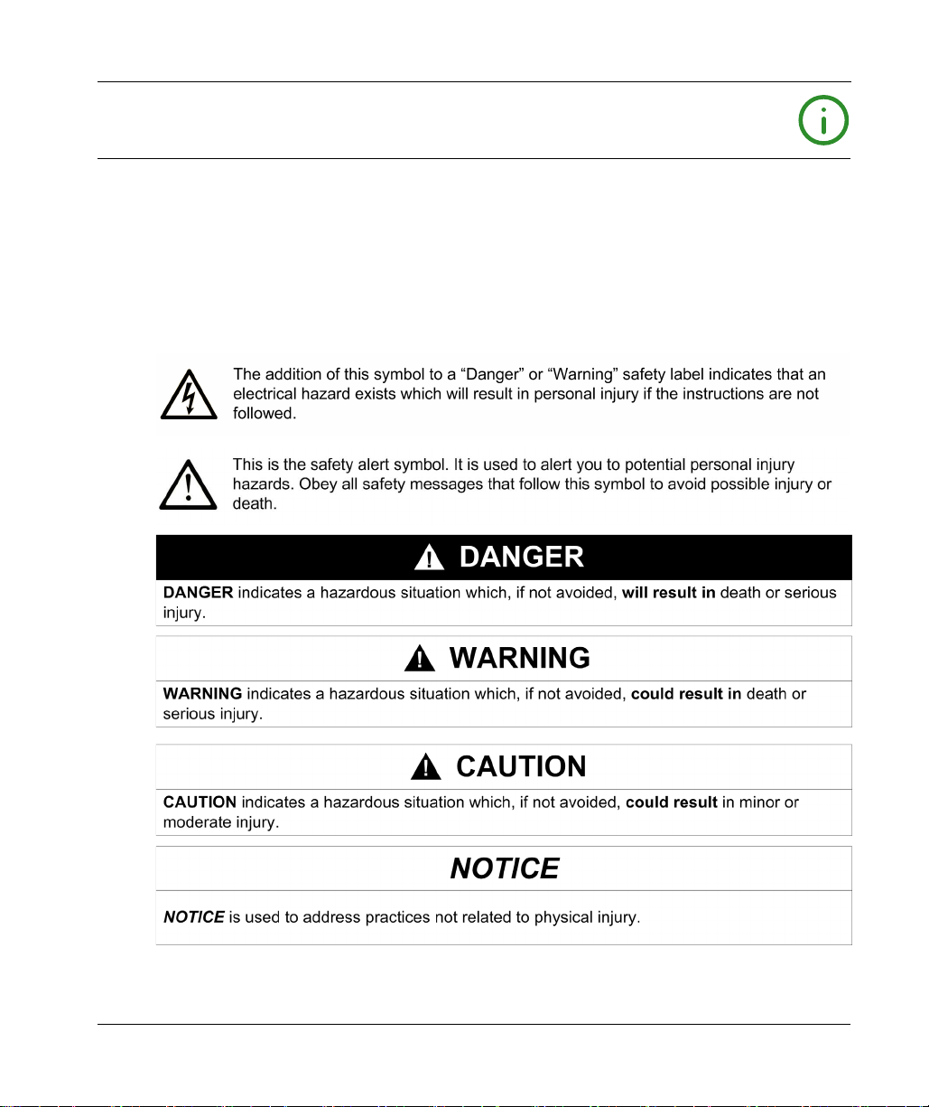
NOTICE
Read these instructions carefully, and look at the equipment to become familiar with the device
before trying to install, operate, service, or maintain it. The following special messages may appear
throughout this documentation or on the equipment to warn of potential hazards or to call attention
to information that clarifies or simplifies a procedure.
EIO0000003125 06/2020 7

PLEASE NOTE
Electrical equipment should be installed, operated, serviced, and maintained only by qualified
personnel. No responsibility is assumed by Schneider Electric for any consequences arising out of
the use of this material.
A qualified person is one who has skills and knowledge related to the construction and operation
of electrical equipment and its installation, and has received safety training to recognize and avoid
the hazards involved.
QUALIFICATION OF PERSONNEL
Only appropriately trained persons who are familiar with and understand the contents of this
manual and all other pertinent product documentation are authorized to work on and with this
product.
The qualified person must be able to detect possible hazards that may arise from parameterization,
modifying parameter values and generally from mechanical, electrical, or electronic equipment.
The qualified person must be familiar with the standards, provisions, and regulations for the
prevention of industrial accidents, which they must observe when designing and implementing the
system.
INTENDED USE
The products described or affected by this document, together with software, accessories, and
options, are expansion modules, intended for industrial use according to the instructions,
directions, examples, and safety information contained in the present document and other
supporting documentation.
The product may only be used in compliance with all applicable safety regulations and directives,
the specified requirements, and the technical data.
Prior to using the product, you must perform a risk assessment in view of the planned application.
Based on the results, the appropriate safety-related measures must be implemented.
Since the product is used as a component in an overall machine or process, you must ensure the
safety of persons by means of the design of this overall system.
Operate the product only with the specified cables and accessories. Use only genuine accessories
and spare parts.
Any use other than the use explicitly permitted is prohibited and can result in unanticipated
hazards.
8 EIO0000003125 06/2020

About the Book
At a Glance
Document Scope
This guide describes the hardware implementation of TM3 digital I/O expansion modules. It
provides the parts description, characteristics, wiring diagrams, and installation details for TM3
digital I/O expansion modules.
Validity Note
This document has been updated for the release of EcoStruxureTM Machine Expert V1.2.4.
The technical characteristics of the devices described in the present document also appear online.
To access the information online, go to the Schneider Electric home page
https://www.se.com/ww/en/download/
The characteristics that are described in the present document should be the same as those
characteristics that appear online. In line with our policy of constant improvement, we may revise
content over time to improve clarity and accuracy. If you see a difference between the document
and online information, use the online information as your reference.
For product compliance and environmental information (RoHS, REACH, PEP, EOLI, etc.), go to
www.schneider-electric.com/green-premium
.
.
EIO0000003125 06/2020 9

Related Documents
Title of Documentation Reference Number
Modicon TM3 Expansion Modules Configuration - Programming
Guide (EcoStruxure Machine Expert - Basic)
Modicon TM3 Expansion Modules Configuration - Programming
Guide (EcoStruxure Machine Expert)
Modicon M221 Logic Controller - Hardware Guide
Modicon M241 Logic Controller - Hardware Guide
Modicon M251 Logic Controller - Hardware Guide
TM3 Digital I/O Modules Instruction Sheet
EIO0000003345 (ENG)
EIO0000003346 (FRE)
EIO0000003347 (GER)
EIO0000003348 (SPA)
EIO0000003349 (ITA)
EIO0000003350 (CHS)
EIO0000003351 (POR)
EIO0000003352 (TUR)
EIO0000003119 (ENG)
EIO0000003120 (FRE)
EIO0000003121 (GER)
EIO0000003122 (SPA)
EIO0000003123 (ITA)
EIO0000003124 (CHS)
EIO0000003313 (ENG)
EIO0000003314 (FRE)
EIO0000003315 (GER)
EIO0000003316 (SPA)
EIO0000003317 (ITA)
EIO0000003318 (CHS)
EIO0000003319 (POR)
EIO0000003320 (TUR)
EIO0000003083 (ENG)
EIO0000003084 (FRE)
EIO0000003085 (GER)
EIO0000003086 (SPA)
EIO0000003087 (ITA)
EIO0000003088 (CHS)
EIO0000003101 (ENG)
EIO0000003102 (FRE)
EIO0000003103 (GER)
EIO0000003104 (SPA)
EIO0000003105 (ITA)
EIO0000003106 (CHS)
HRB59605
You can download these technical publications and other technical information from our website
https://www.se.com/ww/en/download/
at
10 EIO0000003125 06/2020
.
Product Related Information
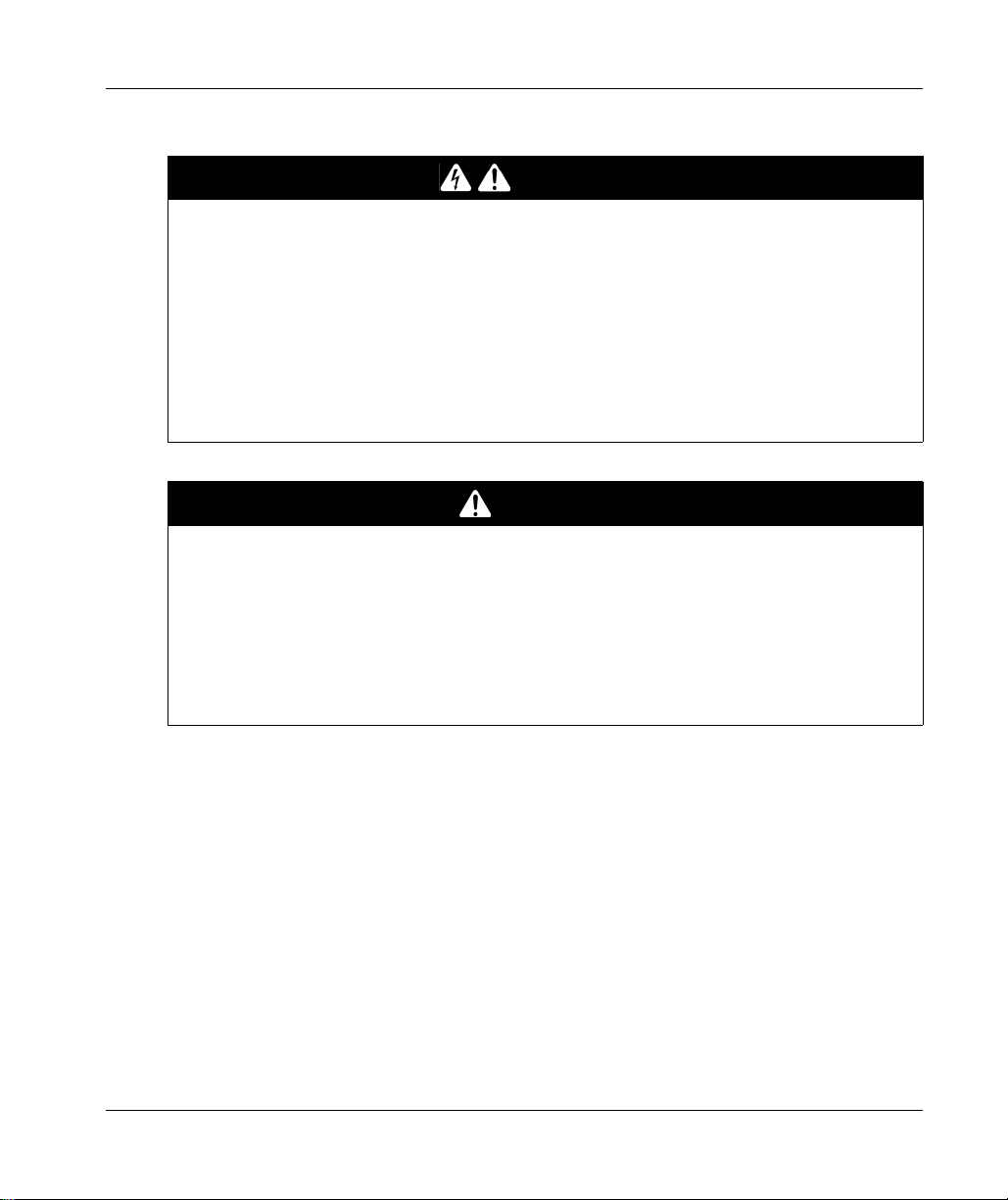
HAZARD OF ELECTRIC SHOCK, EXPLOSION OR ARC FLASH
Disconnect all power from all equipment including connected devices prior to removing any
covers or doors, or installing or removing any accessories, hardware, cables, or wires except
under the specific conditions specified in the appropriate hardware guide for this equipment.
Always use a properly rated voltage sensing device to confirm the power is off where and when
indicated.
Replace and secure all covers, accessories, hardware, cables, and wires and confirm that a
proper ground connection exists before applying power to the unit.
Use only the specified voltage when operating this equipment and any associated products.
Failure to follow these instructions will result in death or serious injury.
POTENTIAL FOR EXPLOSION
Only use this equipment in non-hazardous locations, or in locations that comply with Class I,
Division 2, Groups A, B, C and D.
Do not substitute components which would impair compliance to Class I, Division 2.
Do not connect or disconnect equipment unless power has been removed or the location is
known to be non-hazardous.
Do not use the USB port(s), if so equipped, unless the location is known to be non-hazardous.
Failure to follow these instructions will result in death or serious injury.
DANGER
DANGER
EIO0000003125 06/2020 11
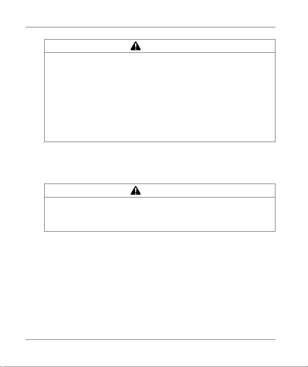
WARNING
LOSS OF CONTROL
The designer of any control scheme must consider the potential failure modes of control paths
and, for certain critical control functions, provide a means to achieve a safe state during and
after a path failure. Examples of critical control functions are emergency stop and overtravel
stop, power outage and restart.
Separate or redundant control paths must be provided for critical control functions.
System control paths may include communication links. Consideration must be given to the
implications of unanticipated transmission delays or failures of the link.
Observe all accident prevention regulations and local safety guidelines.
Each implementation of this equipment must be individually and thoroughly tested for proper
1
operation before being placed into service.
Failure to follow these instructions can result in death, serious injury, or equipment damage.
1
For additional information, refer to NEMA ICS 1.1 (latest edition), "Safety Guidelines for the
Application, Installation, and Maintenance of Solid State Control" and to NEMA ICS 7.1 (latest
edition), "Safety Standards for Construction and Guide for Selection, Installation and Operation of
Adjustable-Speed Drive Systems" or their equivalent governing your particular location.
WARNING
UNINTENDED EQUIPMENT OPERATION
Only use software approved by Schneider Electric for use with this equipment.
Update your application program every time you change the physical hardware configuration.
Failure to follow these instructions can result in death, serious injury, or equipment damage.
12 EIO0000003125 06/2020
Terminology Derived from Standards
The technical terms, terminology, symbols and the corresponding descriptions in this manual, or
that appear in or on the products themselves, are generally derived from the terms or definitions
of international standards.
In the area of functional safety systems, drives and general automation, this may include, but is not
limited to, terms such as
safety, safety function, safe state, fault, fault reset, malfunction, failure
error, error message, dangerous
Among others, these standards include:
Standard Description
IEC 61131-2:2007 Programmable controllers, part 2: Equipment requirements and tests.
ISO 13849-1:2015 Safety of machinery: Safety related parts of control systems.
EN 61496-1:2013 Safety of machinery: Electro-sensitive protective equipment.
ISO 12100:2010 Safety of machinery - General principles for design - Risk assessment and risk
EN 60204-1:2006 Safety of machinery - Electrical equipment of machines - Part 1: General
ISO 14119:2013 Safety of machinery - Interlocking devices associated with guards - Principles
ISO 13850:2015 Safety of machinery - Emergency stop - Principles for design
IEC 62061:2015 Safety of machinery - Functional safety of safety-related electrical, electronic,
IEC 61508-1:2010 Functional safety of electrical/electronic/programmable electronic safety-
IEC 61508-2:2010 Functional safety of electrical/electronic/programmable electronic safety-
IEC 61508-3:2010 Functional safety of electrical/electronic/programmable electronic safety-
IEC 61784-3:2016 Industrial communication networks - Profiles - Part 3: Functional safety
2006/42/EC Machinery Directive
2014/30/EU Electromagnetic Compatibility Directive
2014/35/EU Low Voltage Directive
General principles for design.
Part 1: General requirements and tests.
reduction
requirements
for design and selection
and electronic programmable control systems
related systems: General requirements.
related systems: Requirements for electrical/electronic/programmable
electronic safety-related systems.
related systems: Software requirements.
fieldbuses - General rules and profile definitions.
,
, etc.
EIO0000003125 06/2020 13
In addition, terms used in the present document may tangentially be used as they are derived from
other standards such as:
Standard Description
IEC 60034 series Rotating electrical machines
IEC 61800 series Adjustable speed electrical power drive systems
IEC 61158 series Digital data communications for measurement and control – Fieldbus for use in
industrial control systems
Finally, the term
hazards, and is defined as it is for a
2006/42/EC
(
zone of operation
) and
ISO 12100:2010
may be used in conjunction with the description of specific
hazard zone
or
danger zone
in the
Machinery Directive
.
NOTE: The aforementioned standards may or may not apply to the specific products cited in the
present documentation. For more information concerning the individual standards applicable to the
products described herein, see the characteristics tables for those product references.
14 EIO0000003125 06/2020
ModiconTM3
TM3 General Overview
EIO0000003125 06/2020
TM3 General Overview
Part I
TM3 General Overview
What Is in This Part?
This part contains the following chapters:
Chapter Chapter Name Page
1 TM3 Description 17
2 TM3 Installation 27
EIO0000003125 06/2020 15

TM3 General Overview
16
EIO0000003125 06/2020

ModiconTM3
TM3 Description
EIO0000003125 06/2020
TM3 Description
Chapter 1
TM3 Description
What Is in This Chapter?
This chapter contains the following topics:
General Description 18
Physical Description 22
Accessories 24
Topic Page
EIO0000003125 06/2020 17

TM3 Description
General Description
Introduction
The range of TM3 digital I/O expansion modules includes:
Input modules
Output modules
Mixed input/output modules
All TM3 digital I/O expansion modules are equipped with (depending on the reference):
Removable screw terminal blocks
Removable spring terminal blocks
HE10 (MIL 20) connectors
For modules with HE10 (MIL 20) connectors, a group of products known as Telefast 2 are a v ailable
that enable these modules to be quickly connected to sensors and actuators.
TM3 Digital Input Modules
The following table shows the TM3 digital input expansion modules
corresponding channel type, nominal voltage/current, and terminal type:
(see page 55)
, with
Reference Channels Channel Type Voltage
Current
TM3DI8A
TM3DI8
TM3DI8G
TM3DI16
TM3DI16G
TM3DI16K
TM3DI32K
18
(see page 57)
(see page 63)
(see page 63)
(see page 69)
(see page 69)
(see page 77)
(see page 85)
8 Regular inputs 120 Vac
7.5 mA
8 Regular inputs 24 Vdc
7mA
8 Regular inputs 24 Vdc
7mA
16 Regular inputs 24 Vdc
7mA
16 Regular inputs 24 Vdc
7mA
16 Regular inputs 24 Vdc
5mA
32 Regular inputs 24 Vdc
5mA
Terminal Type / Pitch
Removable screw
terminal block /
5.08 mm
Removable screw
terminal block /
5.08 mm
Removable spring
terminal block /
5.08 mm
Removable screw
terminal blocks /
3.81 mm
Removable spring
terminal blocks /
3.81 mm
HE10 (MIL 20)
connector
HE10 (MIL 20)
connector
EIO0000003125 06/2020

TM3 Digital Output Modules
The following table shows the TM3 digital output expansion modules
corresponding channel type, nominal voltage/current, and terminal type:
(see page 93)
TM3 Description
, with
Reference Channels Channel Type Voltage
Current
TM3DQ8R
TM3DQ8RG
TM3DQ8T
TM3DQ8TG
TM3DQ8U
TM3DQ8UG
TM3DQ16R
TM3DQ16RG
TM3DQ16T
(see page 95)
(see page 95)
(see page 103)
(see page 103)
(see page 109)
(see page 109)
(see page 115)
(see page 115)
(see page 123)
8 Relay outputs 24 Vdc / 240 Vac
7 A maximum per
common line / 2 A
maximum per output
8 Relay outputs 24 Vdc / 240 Vac
7 A maximum per
common line / 2 A
maximum per output
8 Regular transistor
outputs (source)
8 Regular transistor
outputs (source)
8 Regular transistor
outputs (sink)
8 Regular transistor
outputs (sink)
16 Relay outputs 24 Vdc / 240 Vac
16 Relay outputs 24 Vdc / 240 Vac
16 Regular transistor
outputs (source)
24 Vdc
4 A maximum per
common line/0.5 A
maximum per output
24 Vdc
4 A maximum per
common line/0.5 A
maximum per output
24 Vdc
4 A maximum per
common line/0.5 A
maximum per output
24 Vdc
4 A maximum per
common line/0.5 A
maximum per output
8 A maximum per
common line / 2 A
maximum per output
8 A maximum per
common line / 2 A
maximum per output
24 Vdc
8 A maximum per
common line / 0.5 A
maximum per output
Terminal Type / Pitch
Removable screw terminal
block / 5.08 mm
Removable spring terminal
block / 5.08 mm
Removable screw terminal
block / 5.08 mm
Removable spring terminal
block / 5.08 mm
Removable screw terminal
block / 5.08 mm
Removable spring terminal
block / 5.08 mm
Removable screw terminal
blocks / 3.81 mm
Removable spring terminal
blocks / 3.81 mm
Removable screw terminal
blocks / 3.81 mm
EIO0000003125 06/2020 19

TM3 Description
Reference Channels Channel Type Voltage
Current
TM3DQ16TG
TM3DQ16U
TM3DQ16UG
TM3DQ16TK
TM3DQ16UK
TM3DQ32TK
TM3DQ32UK
(see page 123)
(see page 135)
(see page 135)
(see page 129)
(see page 141)
(see page 147)
(see page 155)
16 Regular transistor
outputs (source)
16 Regular transistor
outputs (sink)
16 Regular transistor
outputs (sink)
16 Regular transistor
outputs (source)
16 Regular transistor
outputs (sink)
32 Regular transistor
outputs (source)
32 Regular transistor
outputs (sink)
24 Vdc
8 A maximum per
common line / 0.5 A
maximum per output
24 Vdc
8 A maximum per
common line / 0.5 A
maximum per output
24 Vdc
8 A maximum per
common line / 0.5 A
maximum per output
24 Vdc
2 A maximum per
common line / 0.1 A
maximum per output
24 Vdc
2 A maximum per
common line / 0.1 A
maximum per output
24 Vdc
2 A maximum per
common line / 0.1 A
maximum per output
24 Vdc
2 A maximum per
common line / 0.1 A
maximum per output
Terminal Type / Pitch
Removable spring terminal
blocks / 3.81 mm
Removable screw terminal
blocks / 3.81 mm
Removable spring terminal
blocks / 3.81 mm
HE10 (MIL 20) connector
HE10 (MIL 20) connector
HE10 (MIL 20) connectors
HE10 (MIL 20) connectors
20
EIO0000003125 06/2020

TM3 Digital Mixed Input/Output Modules
This following table shows the TM3 mixed I/O modules
channel type, nominal voltage/current, and terminal type:
(see page 163)
TM3 Description
, with corresponding
Reference Channels Channel Type Voltage
Current
TM3DM8R
TM3DM8RG
TM3DM24R
TM3DM24RG
(see page 165)
(see page 165)
(see page 175)
(see page 175)
4 Regular inputs 24 Vdc
7mA
4 Relay outputs 24 Vdc / 240 Vac
7 A maximum per
common line / 2 A
maximum per output
4 Regular inputs 24 Vdc
7mA
4 Relay outputs 24 Vdc / 240 Vac
7 A maximum per
common line / 2 A
maximum per output
16 Regular inputs 24 Vdc
7mA
8 Relay outputs 24 Vdc / 240 Vac
7 A maximum per
common line / 2 A
maximum per output
16 Regular inputs 24 Vdc
7mA
8 Relay outputs 24 Vdc / 240 Vac
7 A maximum per
common line / 2 A
maximum per output
Terminal Type / Pitch
Removable screw terminal
block / 5.08 mm
Removable spring terminal
block /5.08 mm
Removable screw terminal
blocks / 3.81 mm
Removable spring terminal
blocks / 3.81 mm
EIO0000003125 06/2020 21
TM3 Description
Physical Description
Introduction
This section describes the physical characteristics of the TM3 modules. The modules, depending
on the reference, support one of two different types of connectors:
Removable screw or spring terminal block
HE10 (MIL 20) connector
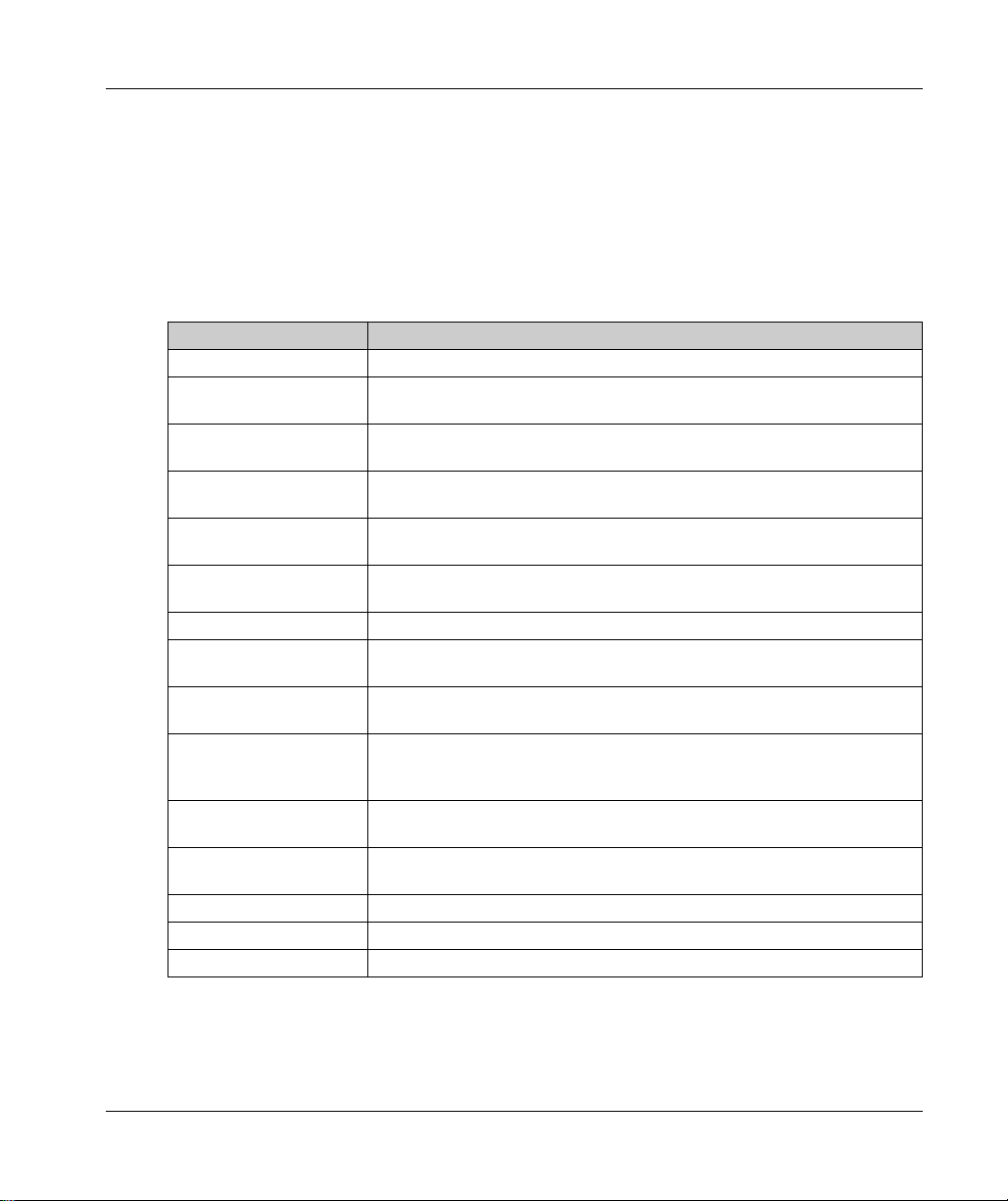
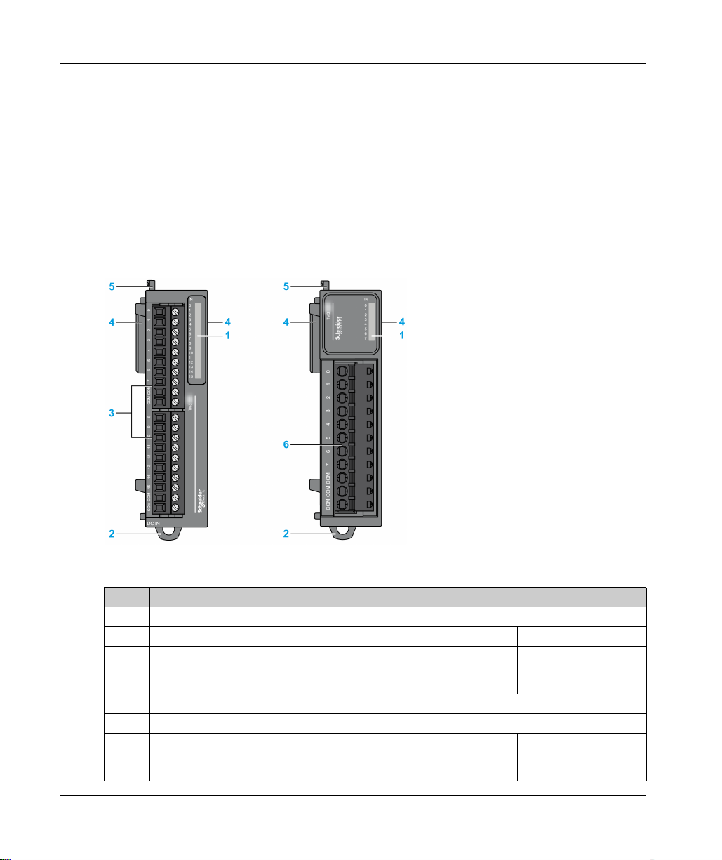
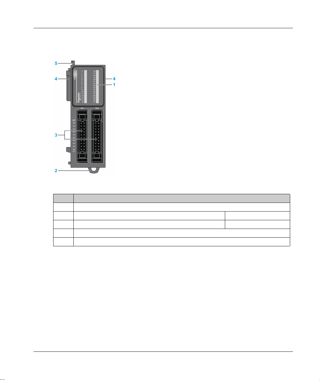
TM3 with Removable Screw or Spring Terminal Block
The following figure shows the main elements of a TM3 expansion module with removable screw
or spring terminal block:
22
This table describes the main elements of the TM3 expansion modules shown above:
Label Elements
1 LEDs for displaying the state of the I/O channel.
2 Clip-on lock for 35 mm (1.38 in.) top hat section rail (DIN-rail). DIN Rail
3 Removable terminal block. Rules for Removable
Screw Terminal Block
(see page 38)
(see page 49)
4 Expansion connector for TM3 I/O bus (one on each side).
5 Locking device for attachment to the previous module.
6 Removable terminal block. Rules for Removable
Spring Terminal Block
(see page 50)
EIO0000003125 06/2020
TM3 with HE10 (MIL 20) Connector
The following figure shows the main elements of a TM3 expansion module with HE10 (MIL 20)
connector:
This table describes the main elements of the TM3 expansion module shown above:
Label Elements
1 LEDs for displaying the state of the I/O channel.
2 Clip-on lock for 35 mm (1.38 in.) top hat section rail (DIN-rail). DIN Rail
3 HE10 (MIL 20) connector socket. Cable list
4 Expansion connector for TM3 I/O bus (one on each side).
5 Locking device for attachment to the previous module.
TM3 Description
(see page 38)
EIO0000003125 06/2020 23
TM3 Description
Accessories
Overview
This section describes the accessories, cables, and Telefast.
Accessories
Reference Description Use Quantity
TMAT2MSET Set of 8 removable screw terminal
blocks:
4 x Removable screw terminal
blocks (pitch 3.81 mm) with 11
terminals for inputs/outputs
4 x Removable screw terminal
blocks (pitch 3.81 mm) with 10
terminals for inputs/outputs
TMAT2MSETG Set of 8 removable spring terminal
blocks:
4 x Removable spring terminal
blocks (pitch 3.81 mm) with 11
terminals for inputs/outputs
4 x Removable spring terminal
blocks (pitch 3.81 mm) with 10
terminals for inputs/outputs
NSYTRAAB35 End brackets Helps secure the controller or receiver
TM2XMTGB Grounding Bar Connects the cable shield and the module to
TM200RSRCEMC Shielding take-up clip Mounts and connects the ground to the
TMAM2 Mounting Kit Mounts the controller and I/O modules
Connects the module I/Os. 1
Connects the module I/Os. 1
1
module and their expansion modules on a
top hat section rail (DIN rail).
1
the functional ground.
25 pack
cable shielding.
1
directly to a flat, vertical panel.
Cables
Reference Description Details Length
TWDFCW30K Digital I/O cables with free
wires for 20-pin Modular
TWDFCW50K 5m
controller
24
Cable equipped at a one end with an HE10
connector. (AWG 22 / 0.34 mm
2
).
3m
(9.84 ft)
(16.4 ft)
EIO0000003125 06/2020
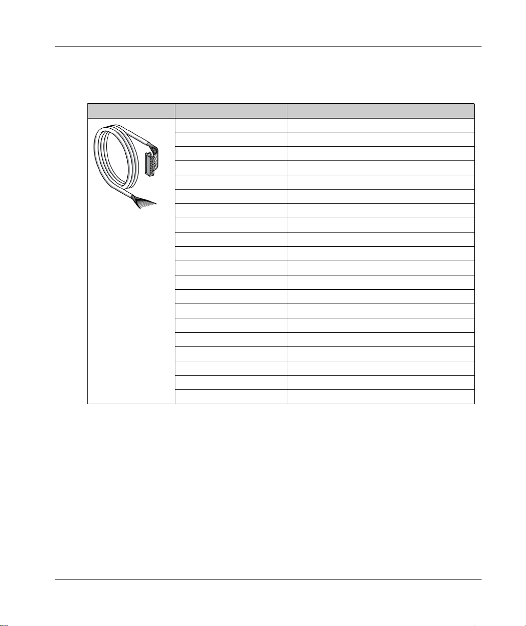
TWDFCW••K Cable Description
The following table provides specifications for the TWDFCW30K/50K with free wires for 20-pin
connectors (HE10 or MIL20):
Cable illustration Pin Connector Wire Color
TM3 Description
1White
2Brown
3 Green
4Yellow
5Grey
6Pink
7Blue
8Red
9Black
10 Violet
11 Grey and pink
12 Red and blue
13 White and green
14 Brown and green
15 White and yellow
16 Yellow and brown
17 White and grey
18 Grey and brown
19 White and pink
20 Pink and brown
EIO0000003125 06/2020 25
TM3 Description
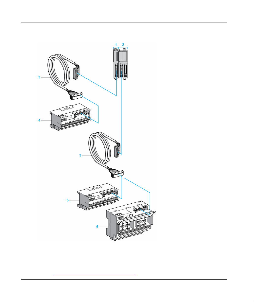
Telefast Pre-Wiring Sub-bases
The following illustration shows the Telefast system:
26
1 TM3DI16K / TM3DI32K
2 TM3DQ16TK / TM3DQ32TK
3 Cable equipped with a 20-way HE 10 connector at each end.)
4 16 channel sub-base for input extension modules.
5–6 16 channel sub-base for output extension modules.
Refer to
TM3 Digital I/O Modules Instruction Sheet
.
EIO0000003125 06/2020
ModiconTM3
TM3 Installation
EIO0000003125 06/2020
TM3 Installation
Chapter 2
TM3 Installation
What Is in This Chapter?
This chapter contains the following sections:
Section Topic Page
2.1 TM3 General Rules for Implementing 28
2.2 TM3 Expansion Module Installation 33
2.3 TM3 Electrical Requirements 46
EIO0000003125 06/2020 27
TM3 Installation
TM3 General Rules for Implementing
Section 2.1
TM3 General Rules for Implementing
What Is in This Section?
This section contains the following topics:
Environmental Characteristics 29
Certifications and Standards 32
Topic Page
28
EIO0000003125 06/2020
Environmental Characteristics
Enclosure Requirements
TM3 expansion module components are designed as Zone B, Class A industrial equipment
according to IEC/CISPR Publication 11. If they are used in environments other than those
described in these standards, or in environments that do not meet the specifications in this manual
the ability to meet electromagnetic compatibility requirements in the presence of conducted and/or
radiated interference may be reduced.
All TM3 expansion module components meet European Community (CE) requirements for open
equipment as defined by IEC/EN 61131-2. You must install them in an enclosure designed for the
specific environmental conditions and to minimize the possibility of unintended contact with
hazardous voltages. Use metal enclosures to improve the electromagnetic immunity of your TM3
expansion module components. Use enclosures with a keyed locking mechanism to minimize
unauthorized access.
Environmental Characteristics
All the TM3 expansion module components are electrically isolated between the internal electronic
circuit and the input/output channels. This equipment meets CE requirements as indicated in the
table below. This equipment is intended for use in a Pollution Degree 2 industrial environment.
UNINTENDED EQUIPMENT OPERATION
Do not exceed any of the rated values specified in the environmental and electrical characteristics
tables.
Failure to follow these instructions can result in death, serious injury, or equipment damage.
TM3 Installation
WARNING
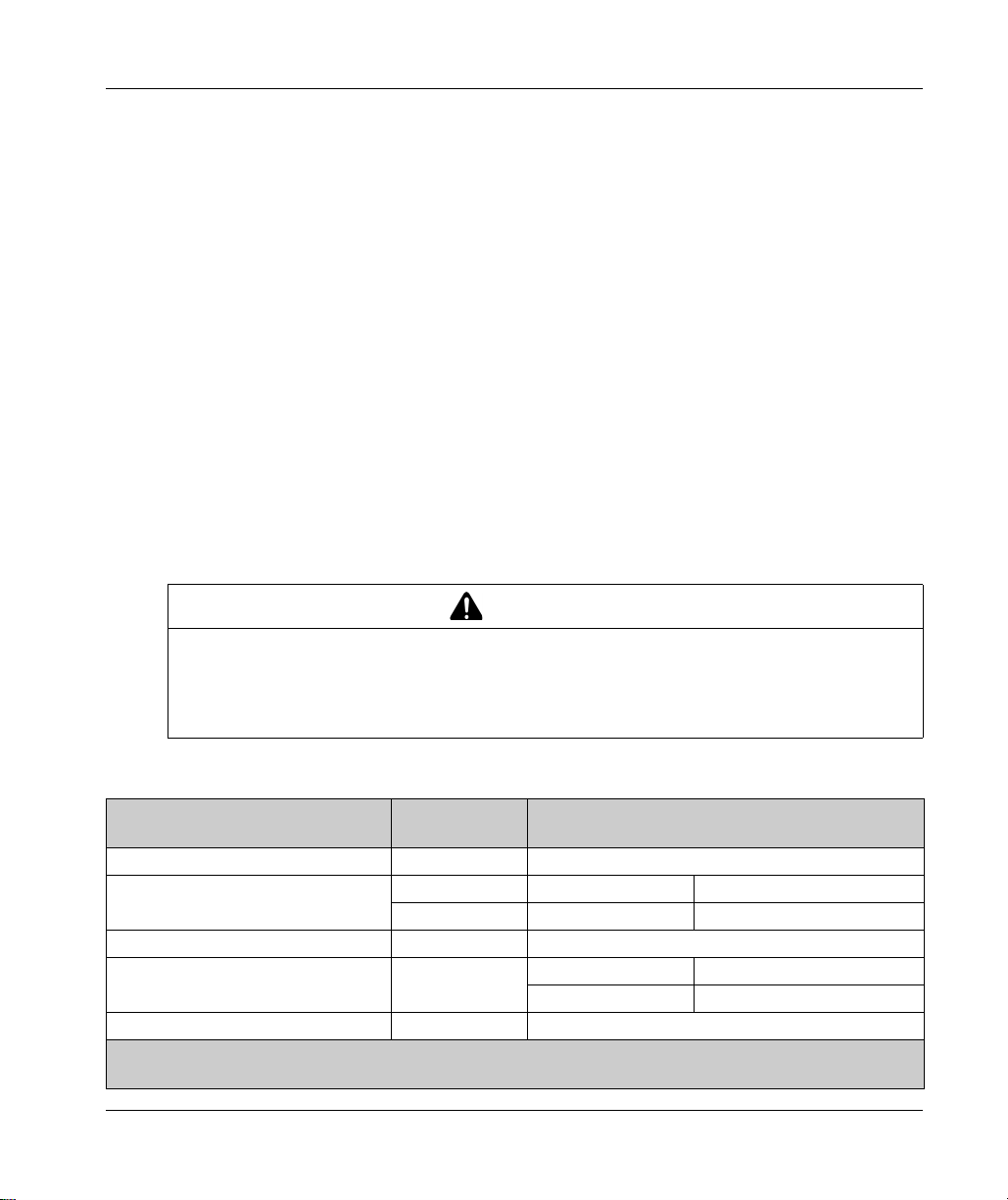
The following table shows the general environmental characteristics:
Characteristic Minimum
Specification
Standard compliance IEC/EN 61131-2 –
Ambient operating temperature – Horizontal installation –10...55 °C (14...131 °F)
– Vertical installation –10...35 °C (14...95 °F)
Storage temperature – –25...70 °C (- 13...158 °F)
Relative humidity – Transport and storage 10...95 % (non-condensing)
Degree of pollution IEC/EN 60664-1 2
Tested Range
Operation 10...95 % (non-condensing)
NOTE: The tested ranges may indicate values beyond that of the IEC Standard. However, our internal standards
define what is necessary for industrial environments. In all cases, we uphold the minimum specification if indicated.
EIO0000003125 06/2020 29
TM3 Installation
Characteristic Minimum
Tested Range
Specification
Degree of protection IEC/EN 61131-2 IP20
Corrosion immunity – Atmosphere free from corrosive gases
Operating altitude – 0...2000 m (0...6560 ft)
Storage altitude – 0...3000 m (0...9843 ft)
Vibration resistance IEC/EN 61131-2 Panel mounting or
mounted on a top hat
section rail (DIN rail)
10 mm (0.39 in) fixed amplitude
from 5...8.7 Hz
29.4 m/s
2
(96.45 ft/s2) (3 gn)
fixed acceleration from
8.7...150 Hz
Mechanical shock resistance –
147 m/s
2
or 482.28 ft/s2 (15 gn) for a duration of 11 ms
NOTE: The tested ranges may indicate values beyond that of the IEC Standard. However, our internal standards
define what is necessary for industrial environments. In all cases, we uphold the minimum specification if indicated.
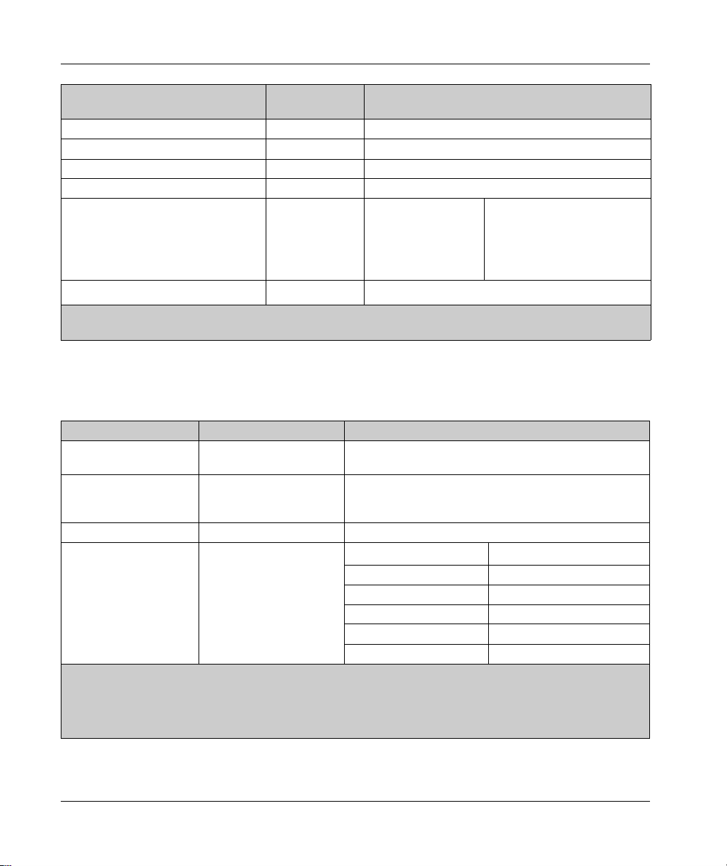
Electromagnetic Susceptibility
The TM3 expansion module components meets electromagnetic susceptibility specifications as
indicated in the following table:
Characteristic Minimum Specification Tested Range
Electrostatic discharge IEC/EN 61000-4-2 8 kV (air discharge)
4 kV (contact discharge)
Radiated electromagnetic
field
Magnetic field IEC/EN 61000-4-8 30 A/m 50 Hz, 60 Hz
Fast transients burst IEC/EN 61000-4-4 –
1 Common Mode
2 Differential Mode
IEC/EN 61000-4-3 10 V/m (80...1000 MHz)
3 V/m (1.4...2 GHz)
1 V/m (2...3 GHz)
AC/DC Power lines –
Relay Outputs 2 kV
24 Vdc I/Os 1 kV
Analog I/Os –
Communication line –
CM
1
and DM
2
NOTE: The tested ranges may indicate values beyond that of the IEC Standard. However, our internal standards
define what is necessary for industrial environments. In all cases, we uphold the minimum specification if indicated.
30
EIO0000003125 06/2020

Characteristic Minimum Specification Tested Range
Surge immunity IEC/EN 61000-4-5
IEC/EN 61131-2
–
DC Power lines 1 kV 0.5 kV
AC Power lines 2 kV 1 kV
Relay Outputs 2 kV 1 kV
24 Vdc I/Os 1 kV –
Shielded cable (between
shield and ground)
Induced electromagnetic
IEC/EN 61000-4-6 10 Vrms (0.15...80 MHz)
field
Conducted emission IEC 61000-6-4 AC power line:
0.15...0.5 MHz: 79 dBμV/m QP / 66 dBμV/m AV
0.5...300 MHz: 73 dBμV/m QP / 60 dBµV/m AV
AC/DC power line:
10...150 kHz: 120...69 dBμV/m QP
150...1500 kHz: 79...63 dBμV/m QP
1.5...30 MHz: 63 dBμV/m QP
Radiated emission IEC 61000-6-4 30...230 MHz: 40 dBμV/m QP
230...1000 MHz: 47 dBμV/m QP
1 Common Mode
2 Differential Mode
TM3 Installation
1
CM
1kV –
DM
2
NOTE: The tested ranges may indicate values beyond that of the IEC Standard. However, our internal standards
define what is necessary for industrial environments. In all cases, we uphold the minimum specification if indicated.
EIO0000003125 06/2020 31

TM3 Installation
Certifications and Standards
Introduction
The TM3 expansion modules are designed to conform to the main national and international
standards concerning electronic industrial control devices:
IEC/EN 61131-2
SV ≥ 2.0
UL 61010-1
UL 61010-2-201
SV < 2.0
UL 508
ANSI/UL 121201
CSA 22.2 n° 213
The TM3 have obtained the following conformity marks:
CE
cULus/CSA
EAC
RCM
cULus/CSA Hazardous Location
For product compliance and environmental information (RoHS, REACH, PEP, EOLI, etc.), go to
www.schneider-electric.com/green-premium
.
32
EIO0000003125 06/2020

TM3 Expansion Module I nstallation
Section 2.2
TM3 Expansion Module Installation
What Is in This Section?
This section contains the following topics:
Installation and Maintenance Requirements 34
Installation Guidelines 37
Top Hat Section Rail (DIN rail) 38
Assembling a Module to a Controller or Receiver Module 41
Disassembling a Module from a Controller or Receiver Module 43
Direct Mounting on a Panel Surface 44
TM3 Installation
Topic Page
EIO0000003125 06/2020 33

TM3 Installation
Installation and Maintenance Requirements
Before Starting
Read and understand this chapter before beginning the installation of your system.
The use and application of the information contained herein require expertise in the design and
programming of automated control systems. Only you, the user, machine builder or integrator, can
be aware of all the conditions and factors present during installation and setup, operation, and
maintenance of the machine or process, and can therefore determine the automation and
associated equipment and the related safeties and interlocks which can be effectively and properly
used. When selecting automation and control equipment, and any other related equipment or
software, for a particular application, you must also consider any applicable local, regional or
national standards and/or regulations.
Pay particular attention in conforming to any safety information, different electrical requirements,
and normative standards that would apply to your machine or process in the use of this equipment.
Disconnecting Power
All options and modules should be assembled and installed before installing the control system on
a mounting rail, onto a mounting plate or in a panel. Remove the control system from its mounting
rail, mounting plate or panel before disassembling the equipment.
HAZARD OF ELECTRIC SHOCK, EXPLOSION OR ARC FLASH
Disconnect all power from all equipment including connected devices prior to removing any
covers or doors, or installing or removing any accessories, hardware, cables, or wires except
under the specific conditions specified in the appropriate hardware guide for this equipment.
Always use a properly rated voltage sensing device to confirm the power is off where and when
indicated.
Replace and secure all covers, accessories, hardware, cables, and wires and confirm that a
proper ground connection exists before applying power to the unit.
Use only the specified voltage when operating this equipment and any associated products.
Failure to follow these instructions will result in death or serious injury.
DANGER
34
EIO0000003125 06/2020

Programming Considerations
UNINTENDED EQUIPMENT OPERATION
Only use software approved by Schneider Electric for use with this equipment.
Update your application program every time you change the physical hardware configuration.
Failure to follow these instructions can result in death, serious injury, or equipment damage.
Operating Environment
In addition to the Environmental Characteristics, refer to Product Related Information in the
beginning of the present document for important information regarding installation in hazardous
locations for this specific equipment.
UNINTENDED EQUIPMENT OPERATION
Install and operate this equipment according to the conditions described in the Environmental
Characteristics.
Failure to follow these instructions can result in death, serious injury, or equipment damage.
TM3 Installation
WARNING
WARNING
EIO0000003125 06/2020 35

TM3 Installation
Installation Considerations
UNINTENDED EQUIPMENT OPERATION
Use appropriate safety interlocks where personnel and/or equipment hazards exist.
Install and operate this equipment in an enclosure appropriately rated for its intended
environment and secured by a keyed or tooled locking mechanism.
Use the sensor and actuator power supplies only for supplying power to the sensors or
actuators connected to the module.
Power line and output circuits must be wired and fused in compliance with local and national
regulatory requirements for the rated current and voltage of the particular equipment.
Do not use this equipment in safety-critical machine functions unless the equipment is
otherwise designated as functional safety equipment and conforming to applicable regulations
and standards.
Do not disassemble, repair, or modify this equipment.
Do not connect any wiring to reserved, unused connections, or to connections designated as
No Connection (N.C.).
Failure to follow these instructions can result in death, serious injury, or equipment damage.
NOTE: JDYX2 or JDYX8 fuse types are UL-recognized and CSA approved.
WARNING
36
EIO0000003125 06/2020

Installation Guidelines
Introduction
TM3 expansion modules are assembled by connecting them to a logic controller or receiver
module.
The logic controller or receiver module and their expansion modules can be installed on a top hat
section rail (DIN rail).
Mounting Position and Minimum Clearances
The mounting position and minimum clearances of the expansion modules must conform with the
rules defined for the appropriate hardware system. Refer to the
Hardware
UNINTENDED EQUIPMENT OPERATION
Place devices dissipating the most heat at the top of the cabinet and ensure adequate
Avoid placing this equipment next to or above devices that might cause overheating.
Install the equipment in a location providing the minimum clearances from all adjacent
Install all equipment in accordance with the specifications in the related documentation.
Failure to follow these instructions can result in death, serious injury, or equipment damage.
documentation for your specific controller.
ventilation.
structures and equipment as directed in this document.
WARNING
Installation chapter
TM3 Installation
in th e
Controller
EIO0000003125 06/2020 37

TM3 Installation
Top Hat Section Rail (DIN rail)
Dimensions of Top Hat Section Rail (DIN Rail)
You can mount the controller or receiver and their expansions on a 35 mm (1.38 in.) top hat section
rail (DIN rail). The DIN rail can be attached to a smooth mounting surface or suspended from a EIA
rack or mounted in a NEMA cabinet.
Symmetric Top Hat Section Rails (DIN Rail)
The following illustration and table indicate the references of the top hat section rails (DIN rail) for
the wall-mounting range:
38
Reference Type Rail Length (B)
NSYSDR50A A 450 mm (17.71 in.)
NSYSDR60A A 550 mm (21.65 in.)
NSYSDR80A A 750 mm (29.52 in.)
NSYSDR100A A 950 mm (37.40 in.)
EIO0000003125 06/2020

TM3 Installation
The following illustration and table indicate the references of the symmetric top hat section rails
(DIN rail) for the metal enclosure range:
Reference Type Rail Length (B-12 mm)
NSYSDR60 A 588 mm (23.15 in.)
NSYSDR80 A 788 mm (31.02 in.)
NSYSDR100 A 988 mm (38.89 in.)
NSYSDR120 A 1188 mm (46.77 in.)
The following illustration and table indicate the references of the symmetric top hat section rails
(DIN rail) of 2000 mm (78.74 in.):
Reference Type Rail Length
NSYSDR200
NSYSDR200D
1
2
A 2000 mm (78.74 in.)
A
1 Unperforated galvanized steel
2 Perforated galvanized steel
EIO0000003125 06/2020 39

TM3 Installation
Double-Profile Top Hat Section Rails (DIN rail)
The following illustration and table indicate the references of the double-profile top hat section rails
(DIN rails) for the wall-mounting range:
Reference Type Rail Length (B)
NSYDPR25 W 250 mm (9.84 in.)
NSYDPR35 W 350 mm (13.77 in.)
NSYDPR45 W 450 mm (17.71 in.)
NSYDPR55 W 550 mm (21.65 in.)
NSYDPR65 W 650 mm (25.60 in.)
NSYDPR75 W 750 mm (29.52 in.)
40
The following illustration and table indicate the references of the double-profile top hat section rails
(DIN rail) for the floor-standing range:
Reference Type Rail Length (B)
NSYDPR60 F 588 mm (23.15 in.)
NSYDPR80 F 788 mm (31.02 in.)
NSYDPR100 F 988 mm (38.89 in.)
NSYDPR120 F 1188 mm (46.77 in.)
EIO0000003125 06/2020

Assembling a Module to a Controller or Receiver Module
Introduction
This section describes how to assemble an expansion module to a controller, Receiver module or
other modules.
DANGER
HAZARD OF ELECTRIC SHOCK, EXPLOSION OR ARC FLASH
Disconnect all power from all equipment including connected devices prior to removing any
covers or doors, or installing or removing any accessories, hardware, cables, or wires except
under the specific conditions specified in the appropriate hardware guide for this equipment.
Always use a properly rated voltage sensing device to confirm the power is off where and when
indicated.
Replace and secure all covers, accessories, hardware, cables, and wires and confirm that a
proper ground connection exists before applying power to the unit.
Use only the specified voltage when operating this equipment and any associated products.
Failure to follow these instructions will result in death or serious injury.
After connecting new modules to the controller, either directly or through a transmitter/receiver,
update and redownload your application program before placing the system back in service. If you
do not revise your application program to reflect the addition of new modules, I/O located on the
expansion bus may no longer operate normally.
TM3 Installation
WARNING
UNINTENDED EQUIPMENT OPERATION
Only use software approved by Schneider Electric for use with this equipment.
Update your application program every time you change the physical hardware configuration.
Failure to follow these instructions can result in death, serious injury, or equipment damage.
EIO0000003125 06/2020 41

TM3 Installation
Assembling a Module to a Controller or Receiver Module
The following procedure shows how to assemble a controller or receiver module and a module
together.
Step Action
1 Remove all power and dismount any existing controller I/O assembly from its DIN mounting.
2 Remove the expansion connector sticker from the controller or the outermost installed expansion
module.
3 Verify that the locking device
Guide)
on the new module is in the upper position.
4 Align the internal bus connector on the left side of the module with the internal bus connector on the
right side of the controller, Receiver module or expansion module.
5 Press the new module towards the controller, Receiver module or expansion module until it is
securely in place.
6 Push down the locking device
Guide)
on the top of the new module to lock it to the controller, Receiver module or previously
installed expansion module.
(see Modicon TM3, Transmitter and Receiver Modules, Hardware
(see Modicon TM3, Transmitter and Receiver Modules, Hardware
42
EIO0000003125 06/2020

Disassembling a Module from a Controller or Receiver Module
Introduction
This section describes how to disassemble a module from a controller or receiver module.
DANGER
HAZARD OF ELECTRIC SHOCK, EXPLOSION OR ARC FLASH
Disconnect all power from all equipment including connected devices prior to removing any
covers or doors, or installing or removing any accessories, hardware, cables, or wires except
under the specific conditions specified in the appropriate hardware guide for this equipment.
Always use a properly rated voltage sensing device to confirm the power is off where and when
indicated.
Replace and secure all covers, accessories, hardware, cables, and wires and confirm that a
proper ground connection exists before applying power to the unit.
Use only the specified voltage when operating this equipment and any associated products.
Failure to follow these instructions will result in death or serious injury.
Disassembling a Module from a Controller or Receiver Module
The following procedure describes how to disassemble a module from a controller or receiver
module.
TM3 Installation
Step Action
1 Remove all power from the control system.
2 Dismount the assembled controller and modules from the mounting rail.
3 Push up the locking device
controller or receiver module.
4 Pull apart module from the controller or receiver module.
EIO0000003125 06/2020 43
(see page 22)
from the bottom of the module to disengage it from the

TM3 Installation
Direct Mounting on a Panel Surface
Overview
This section shows how to install TM3 expansion module using the Panel Mounting Kit. This
section also provides mounting hole layout for all modules.
Installing the Panel Mount Kit
The following procedure shows how to install a mounting strip:
Step Action
1 Insert the mounting strip TMAM2 into the slot at the top of the module.
Mounting Hole Layout
The following diagram shows the mounting holes for TM3 with 8 I/Os ,16 I/Os ,TM3XTRA1 ,
TM3XREC1 and TM3XTYS4 expansion modules:
44
EIO0000003125 06/2020

TM3 Installation
The following diagram shows the mounting holes for TM3 with 24 screw or spring I/O channels:
The following diagram shows the mounting holes for TM3 with 32 HE10 (MIL 20) I/O channels:
EIO0000003125 06/2020 45

TM3 Installation
TM3 Electrical Requirements
Section 2.3
TM3 Electrical Requirements
What Is in This Section?
This section contains the following topics:
Wiring Best Practices 47
DC Power Supply Characteristics 53
Topic Page
46
EIO0000003125 06/2020

Wiring Best Practices
Overview
This section describes the wiring guidelines and associated best practices to be respected when
using the TM3 system.
HAZARD OF ELECTRIC SHOCK, EXPLOSION OR ARC FLASH
Disconnect all power from all equipment including connected devices prior to removing any
covers or doors, or installing or removing any accessories, hardware, cables, or wires except
under the specific conditions specified in the appropriate hardware guide for this equipment.
Always use a properly rated voltage sensing device to confirm the power is off where and when
indicated.
Replace and secure all covers, accessories, hardware, cables, and wires and confirm that a
proper ground connection exists before applying power to the unit.
Use only the specified voltage when operating this equipment and any associated products.
Failure to follow these instructions will result in death or serious injury.
LOSS OF CONTROL
The designer of any control scheme must consider the potential failure modes of control paths
and, for certain critical control functions, provide a means to achieve a safe state during and
after a path failure. Examples of critical control functions are emergency stop and overtravel
stop, power outage and restart.
Separate or redundant control paths must be provided for critical control functions.
System control paths may include communication links. Consideration must be given to the
implications of unanticipated transmission delays or failures of the link.
Observe all accident prevention regulations and local safety guidelines.
Each implementation of this equipment must be individually and thoroughly tested for proper
operation before being placed into service.
Failure to follow these instructions can result in death, serious injury, or equipment damage.
TM3 Installation
DANGER
WARNING
1
1
For additional information, refer to NEMA ICS 1.1 (latest edition), "Safety Guidelines for the
Application, Installation, and Maintenance of Solid State Control" and to NEMA ICS 7.1 (latest
edition), "Safety Standards for Construction and Guide for Selection, Installation and Operation of
Adjustable-Speed Drive Systems" or their equivalent governing your particular location.
EIO0000003125 06/2020 47

TM3 Installation
Functional Ground (FE) on the DIN Rail
The DIN Rail for your TM3 system is common with the functional ground (FE) plane and must be
mounted on a conductive backplane.
UNINTENDED EQUIPMENT OPERATION
Connect the DIN rail to the functional ground (FE) of your installation.
Failure to follow these instructions can result in death, serious injury, or equipment damage.
Protective Ground (PE) on the Backplane
The protective ground (PE) is connected to the conductive backplane by a heavyduty wire, usually
a braided copper cable with the maximum allowable cable section.
Wiring Guidelines
The following rules must be applied when wiring a TM3 system:
I/O and communication wiring must be kept separate from the power wiring. Route these 2 types
of wiring in separate cable ducting.
Verify that the operating conditions and environment are within the specification values.
Use proper wire sizes to meet voltage and current requirements.
Use copper conductors.
Use twisted-pair, shielded cables for analog, and/or fast I/O.
Use twisted-pair, shielded cables for networks, and field bus.
WARNING
48
WARNING
UNINTENDED EQUIPMENT OPERATION
Use shielded cables for all fast I/O, analog I/O, and communication signals.
Ground cable shields for all fast I/O, analog I/O, and communication signals at a single point
Route communications and I/O cables separately from power cables.
Failure to follow these instructions can result in death, serious injury, or equipment damage.
1
Multipoint grounding is permissible if connections are made to an equipotential ground plane
dimensioned to help avoid cable shield damage in the event of power system short-circuit currents.
NOTE: Surface temperatures may exceed 60 °C (140 °F).
To conform to IEC 61010 standards, route primary wiring (wires connected to power mains)
separately and apart from secondary wiring (extra low voltage wiring coming from intervening
power sources). If that is not possible, double insulation is required such as conduit or cable gains.
EIO0000003125 06/2020
1
.

Rules for Removable Screw Terminal Block
The following tables show the cable types and wire sizes for a 3.81 pitch removable screw terminal
block (I/Os and power supply):
The following tables show the cable types and wire sizes for a 5.08 pitch removable screw terminal
block (I/Os and power supply):
The use of copper conductors is required.
TM3 Installation
DANGER
FIRE HAZARD
Use only the correct wire sizes for the maximum current capacity of the I/O channels and
power supplies.
For relay output (2 A) wiring, use conductors of at least 0.5 mm
rating of at least 80 °C (176 °F).
For common conductors of relay output wiring (7 A), or relay output wiring greater than 2 A,
use conductors of at least 1.0 mm2 (AWG 16) with a temperature rating of at least 80 °C
(176 °F).
Failure to follow these instructions will result in death or serious injury.
EIO0000003125 06/2020 49
2
(AWG 20) with a temperature

TM3 Installation
Rules for Removable Spring Terminal Block
The following tables show the cable types and wire sizes for a 3.81 pitch removable spring terminal
block (I/Os and power supply):
The following tables show the cable types and wire sizes for a 5.08 pitch removable spring terminal
block (I/Os and power supply):
The use of copper conductors is required.
FIRE HAZARD
Use only the correct wire sizes for the maximum current capacity of the I/O channels and
power supplies.
For relay output (2 A) wiring, use conductors of at least 0.5 mm
rating of at least 80 °C (176 °F).
For common conductors of relay output wiring (7 A), or relay output wiring greater than 2 A,
use conductors of at least 1.0 mm
(176 °F).
Failure to follow these instructions will result in death or serious injury.
DANGER
2
(AWG 20) with a temperature
2
(AWG 16) with a temperature rating of at least 80 °C
50
The spring clamp connectors of the terminal block are designed for only one wire or one cable end.
Two wires to the same connector must be installed with a double wire cable end to help prevent
loosening.
DANGER
LOOSE WIRING CAUSES ELECTRIC SHOCK
Do not insert more than one wire per connector of the spring terminal blocks unless using a
double wire cable end (ferrule).
Failure to follow these instructions will result in death or serious injury.
EIO0000003125 06/2020

Protecting Outputs from Inductive Load Damage
Depending on the load, a protection circuit may be needed for the outputs on the controllers and
certain modules. Inductive loads using DC voltages may create voltage reflections resulting in
overshoot that will damage or shorten the life of output devices.
OUTPUT CIRCUIT DAMAGE DUE TO INDUCTIVE LOADS
Use an appropriate external protective circuit or device to reduce the risk of inductive direct
current load damage.
Failure to follow these instructions can result in injury or equipment damage.
If your controller or module contains relay outputs, these types of outputs can support up to
240 Vac. Inductive damage to these types of outputs can result in welded contacts and loss of
control. Each inductive load must include a protection device such as a peak limiter, RC circuit or
flyback diode. Capacitive loads are not supported by these relays.
RELAY OUTPUTS WELDED CLOSED
Always protect relay outputs from inductive alternating current load damage using an
appropriate external protective circuit or device.
Do not connect relay outputs to capacitive loads.
Failure to follow these instructions can result in death, serious injury, or equipment damage.
TM3 Installation
CAUTION
WARNING
AC-driven contactor coils are, under certain circumstances, inductive loads that generate
pronounced high-frequency interference and electrical transients when the contactor coil is deenergized. This interference may cause the logic controller to detect an I/O bus error.
WARNING
CONSEQUENTIAL LOSS OF CONTROL
Install an RC surge suppressor or similar means, such as an interposing relay, on each TM3
expansion module relay output when connecting to AC-driven contactors or other forms of
inductive loads.
Failure to follow these instructions can result in death, serious injury, or equipment damage.
EIO0000003125 06/2020 51

TM3 Installation
Protective circuit A: this protection circuit can be used for both AC and DC load power circuits.
C represents a value from 0.1 to 1 μF.
R represents a resistor of approximately the same resistance value as the load.
Protective circuit B: this protection circuit can be used for DC load power circuits.
Use a diode with the following ratings:
Reverse withstand voltage: power voltage of the load circuit x 10.
Forward current: more than the load current.
Protective circuit C: this protection circuit can be used for both AC and DC load power circuits.
52
In applications where the inductive load is switched on and off frequently and/or rapidly, ensure
that the continuous energy rating (J) of the varistor exceeds the peak load energy by 20 % or
more.
EIO0000003125 06/2020

DC Power Supply Characteristics
Overview
This section provides the characteristics of the DC power supply.
Power Supply Voltage Range
If the specified voltage range is not maintained, outputs may not switch as expected. Use
appropriate safety interlocks and voltage monitoring circuits.
FIRE HAZARD
Use only the correct wire sizes for the maximum current capacity of the I/O channels and power
supplies.
Failure to follow these instructions will result in death or serious injury.
UNINTENDED EQUIPMENT OPERATION
Do not exceed any of the rated values specified in the environmental and electrical characteristics
tables.
Failure to follow these instructions can result in death, serious injury, or equipment damage.
TM3 Installation
DANGER
WARNING
EIO0000003125 06/2020 53

TM3 Installation
DC Power Supply Characteristics
The 24 Vdc power supplies must be rated at least Protective Extra Low Voltage (PELV) according
to IEC 61140. These power supplies are isolated between the electrical input and output circuits
of the power supply.
POTENTIAL OF OVERHEATING AND FIRE
Do not connect the equipment directly to line voltage.
Use only isolating PELV power supplies to supply power to the equipment
Failure to follow these instructions can result in death, serious injury, or equipment damage.
1
For compliance to UL (Underwriters Laboratories) requirements, the power supply must also
conform to the various criteria of NEC Class 2, and be inherently current limited to a maximum
power output availability of less than 100 VA (approximately 4 A at nominal voltage), or not
inherently limited but with an additional protection device such as a circuit breaker or fuse meeting
the requirements of clause 9.4 Limited-energy circuit of UL 61010-1. In all cases, the current limit
should never exceed that of the electric characteristics and wiring diagrams for the equipment
described in the present documentation. In all cases, the power supply must be grounded, and you
must separate Class 2 circuits from other circuits. If the indicated rating of the electrical characteristics or wiring diagrams are greater than the specified current limit, multiple Class 2 power
supplies may be used.
WARNING
1
.
54
EIO0000003125 06/2020

ModiconTM3
TM3 Digital Input Modules
EIO0000003125 06/2020
TM3 Digital Input Modules
Part II
TM3 Digital Input Modules
What Is in This Part?
This part contains the following chapters:
Chapter Chapter Name Page
3 TM3DI8A Module 8 Inputs 120 Vac 57
4 TM3DI8 / TM3DI8G Module 8 Regular Inputs 24 Vdc 63
5 TM3DI16 / TM3DI16G Module 16 Regular Inputs 24 Vdc 69
6 TM3DI16K Module 16 Regular Inputs 24 Vdc 77
7 TM3DI32K Module 32 Regular Inputs 24 Vdc 85
EIO0000003125 06/2020 55

TM3 Digital Input Modules
56
EIO0000003125 06/2020

ModiconTM3
TM3DI8A Module 8 Inputs 120Vac
EIO0000003125 06/2020
TM3DI8A Module 8 Inputs 120Vac
Chapter 3
TM3DI8A Module 8 Inputs 120 Vac
Overview
This chapter describes the TM3DI8A expansion modules, its characteristics, and its connection to
the different sensors.
What Is in This Chapter?
This chapter contains the following topics:
TM3DI8A Presentation 58
TM3DI8A Characteristics 59
TM3DI8A Wiring Diagram 61
Topic Page
EIO0000003125 06/2020 57

TM3DI8A Module 8 Inputs 120 Vac
TM3DI8A Presentation
Overview
TM3DI8A (screw) digital expansion module:
8 channels
120 Vac digital input
2 common lines
removable screw terminal block
Main Characteristics
Characteristic Value
Number of input channels 8
Input type Type 1 (IEC/EN 61131-2)
Logic type N/A
Rated input voltage 120 Vac
Connection type Removable screw terminal block
Cable type and length Type stranded wire 2,5 mm²
Status LEDs
The following figure shows the status LEDs:
Length -
58
This table describes the status LEDs:
LED Color Status Description
0...7 Green On The input channel is activated.
Off The input channel is deactivated.
EIO0000003125 06/2020

TM3DI8A Characteristics
Introduction
This section provides a general description of the characteristics of the TM3DI8A expansion
module.
See also Environmental Characteristics
UNINTENDED EQUIPMENT OPERATION
Do not exceed any of the rated values specified in the environmental and electrical characteristics
tables.
Failure to follow these instructions can result in death, serious injury, or equipment damage.
Dimensions
The following diagrams show the external dimensions for the TM3DI8A module:
(see page 29)
.
WARNING
TM3DI8A Module 8 Inputs 120 Vac
* 8.5 mm (0.33 in.) when the clamp is pulled out.
EIO0000003125 06/2020 59

TM3DI8A Module 8 Inputs 120 Vac
Input Characteristics
The table below describes the inputs characteristics of the TM3DI8A expansion module:
Characteristic Value
Number of input channels 8 inputs
Number of channels groups 2 common lines of 4 channels each
Input type Type 1 (IEC/EN 61131-2))
Logic type N/A
Rated input voltage 120 Vac
Input voltage range 0...132 Vac
Rated input current 7.5 mA at 100 Vac
Input impedance 11 kΩ
Turn on time 25 ms
De-rating -10...55 °C
(14...131 °F)
Input limit values Voltage at state 1 > 79 Vac (79...132 Vac)
Voltage at state 0 < 20 Vac (0...20 Vac)
Current at state 1 2 mA < I < 15 mA
Isolation Between input and internal logic 1500 Vac
Between input groups 1500 Vac
Connector type Removable screw terminal block
Connector insertion/removal durability Over 100 times
Current draw on 5 Vdc internal bus 60 mA (all inputs on)
Current draw on 24 Vdc internal bus 0 mA (all inputs on)
No de-rating
25 mA (all inputs off)
0 mA (all inputs off)
60
EIO0000003125 06/2020

TM3DI8A Wiring Diagram
Introduction
This expansion module has a built-in removable screw terminal block for the connection of inputs
and power supply.
Wiring Rules
See Wiring Best Practices
Wiring Diagram
The following figure illustrates the connection between the inputs, the sensors, and their commons:
(see page 47)
TM3DI8A Module 8 Inputs 120 Vac
.
The COM0 and COM1 terminal are not connected internally.
WARNING
UNINTENDED EQUIPMENT OPERATION
Do not connect wires to unused terminals and/or terminals indicated as “No Connection (N.C.)”.
Failure to follow these instructions can result in death, serious injury, or equipment damage.
EIO0000003125 06/2020 61

TM3DI8A Module 8 Inputs 120 Vac
62
EIO0000003125 06/2020

ModiconTM3
TM3DI8 / TM3DI8G Module 8 Regula r Inputs 24 Vdc
EIO0000003125 06/2020
TM3DI8 / TM3DI8G Module 8 Regula r Inputs 24 Vdc
Chapter 4
TM3DI8 / TM3DI8G Module 8 Regular Inputs 24 Vdc
Overview
This chapter describes the TM3DI8 / TM3DI8G expansion modules, its characteristics and its
connection to the different sensors.
What Is in This Chapter?
This chapter contains the following topics:
TM3DI8 / TM3DI8G Presentation 64
TM3DI8 / TM3DI8G Characteristics 66
TM3DI8 / TM3DI8G Wiring Diagram 68
Topic Page
EIO0000003125 06/2020 63

TM3DI8 / TM3DI8G Module 8 Regular Inputs 24 Vdc
TM3DI8 / TM3DI8G Presentation
Overview
TM3DI8 (screw) and TM3DI8G (spring) digital expansion module:
8 channels
24 Vdc digital input
1 common line
Sink/source
removable screw or spring terminal block
Main Characteristics
Characteristic Value
Number of input channels 8 inputs
Input type Type 1 (IEC/EN 61131-2)
Logic type Sink/Source
Rated input voltage 24 Vdc
Connection type TM3DI8 Removable screw terminal block
TM3DI8G Removable spring terminal block
Cable type and length Type Unshielded
Length Max. 30 m (98 ft)
Weight 85g (3 oz)
64
EIO0000003125 06/2020

Status LEDs
The following figure shows the status LEDs:
This table describes the status LEDs:
LED Color Status Description
0...7 Green On The input channel is activated
TM3DI8 / TM3DI8G Module 8 Regular Inputs 24 Vdc
Off The input channel is deactivated
EIO0000003125 06/2020 65

TM3DI8 / TM3DI8G Module 8 Regular Inputs 24 Vdc
TM3DI8 / TM3DI8G Characteristics
Introduction
This section provides a description of the input characteristics of TM3DI8 / TM3DI8G expansion
modules.
See also Environmental Characteristics
UNINTENDED EQUIPMENT OPERATION
Do not exceed any of the rated values specified in the environmental and electrical characteristics
tables.
Failure to follow these instructions can result in death, serious injury, or equipment damage.
Dimensions
The following diagrams show the external dimensions for the TM3DI8 / TM3DI8G expansion
modules:
(see page 29)
.
WARNING
66
* 8.5 mm (0.33 in.) when the clamp is pulled out.
EIO0000003125 06/2020

TM3DI8 / TM3DI8G Module 8 Regular Inputs 24 Vdc
Input Characteristics
The table below describes the inputs characteristics of the TM3DI8 / TM3DI8G:
Characteristic Value
Number of input channels 8 inputs
Number of channels groups 1 common line on three terminals for 8 channels
Input type Type 1 (IEC/EN 61131-2)
Logic type Sink/Source
Rated input voltage 24 Vdc
Input voltage range 19.2...28.8 Vdc
Rated input current 7 mA
Input impedance 3.4 kΩ
Turn on time
Turn off time
Input limit values Voltage at state 1 > 15 Vdc (15...28.8 Vdc)
Voltage at state 0 < 5 Vdc (0...5 Vdc)
Current at state 1 > 2.5 mA
Current at state 0 <1 mA
Isolation Between input and
internal logic
Between input groups N/A
Connection type TM3DI8 Removable screw terminal block
TM3DI8G Removable spring terminal block
Connector insertion/removal durability Over 100 times
Current draw on 5 Vdc internal bus 22 mA (all inputs on)
Current draw on 24 Vdc internal bus 0 mA (all inputs on)
(1) SV refers to the version and is printed on the product label.
(1)
< 2.0: 4 ms
SV
(1)
SV
≥ 2.0: 100 μs
500 Vac
5 mA (all inputs off)
0 mA (all inputs off)
(2)
(2) The range depends on the configured filter value. If you use EcoStruxure Machine Expert - Basic, refer to the
Modicon TM3 (EcoStruxure Machine Expert - Basic) Expansion Modules Configuration - Programming Guide. If
you use EcoStruxure Machine Expert, refer to the Modicon TM3 Expansion Modules - Programming Guide.
EIO0000003125 06/2020 67

TM3DI8 / TM3DI8G Module 8 Regular Inputs 24 Vdc
TM3DI8 / TM3DI8G Wiring Diagram
Introduction
These expansion modules have a built-in removable screw or spring terminal block for the
connection of inputs and power supply.
Wiring Rules
See Wiring Best Practices
Wiring Diagram
The following figure illustrates the connection between the inputs, the sensors, and their commons:
(see page 47)
.
68
The 3 COM terminals are connected internally.
A Sink wiring (positive logic)
B Source wiring (negative logic)
For information about 24 Vdc power supply, refer to DC Power Supply Characteristics
(see page 53)
.
EIO0000003125 06/2020

ModiconTM3
TM3DI16 / TM3DI16G Module 16 Regular Inputs 24 Vdc
EIO0000003125 06/2020
TM3DI16 / TM3DI16G Module 16 Regular Inputs 24 Vdc
Chapter 5
TM3DI16 / TM3DI16G Module 16 Regular Inputs 24 Vdc
Overview
This chapter describes the TM3DI16 / TM3DI16G expansion modules, its characteristics and its
connection to the different sensors.
What Is in This Chapter?
This chapter contains the following topics:
TM3DI16 / TM3DI16G Presentation 70
TM3DI16 / TM3DI16G Characteristics 72
TM3DI16 / TM3DI16G Wiring Diagrams 75
Topic Page
EIO0000003125 06/2020 69

TM3DI16 / TM3DI16G Module 16 Regular Inputs 24 Vdc
TM3DI16 / TM3DI16G Presentation
Overview
TM3DI16 (screw) and TM3DI16G (spring) digital expansion module:
16 channels
24 Vdc digital input
1 common line
Sink/source
Removable screw or spring terminal block
Main Characteristics
Characteristic Value
Number of input channels 16
Input type Type 1 (IEC/EN 61131-2)
Logic type Sink/Source
Rated input voltage 24 Vdc
Connection type TM3DI16 Removable screw terminal blocks
TM3DI16G Removable spring terminal blocks
Cable type and length Type Unshielded
Length Max. 30 m (98 ft)
Weight 100 g (3.52 oz)
70
EIO0000003125 06/2020

Status LEDs
The following figure show the status LEDs:
This table describes the status LEDs:
LED Color Status Description
0...15 Green On The input channel is activated
TM3DI16 / TM3DI16G Module 16 Regular Inputs 24 Vdc
Off The input channel is deactivated
EIO0000003125 06/2020 71

TM3DI16 / TM3DI16G Module 16 Regular Inputs 24 Vdc
TM3DI16 / TM3DI16G Characteristics
Introduction
This section provides a description of the input characteristics of TM3DI16 / TM3DI16G expansion
modules.
See also Environmental Characteristics
UNINTENDED EQUIPMENT OPERATION
Do not exceed any of the rated values specified in the environmental and electrical characteristics
tables.
Failure to follow these instructions can result in death, serious injury, or equipment damage.
Dimensions
The following diagrams show the external dimensions for the TM3DI16 / TM3DI16G expansion
modules:
(see page 29)
.
WARNING
72
* 8.5 mm (0.33 in.) when the clamp is pulled out.
EIO0000003125 06/2020

TM3DI16 / TM3DI16G Module 16 Regular Inputs 24 Vdc
Input Characteristics
The table below describes the inputs characteristics of the TM3DI16 / TM3DI16G:
Characteristic Value
Number of input channels 16 inputs
Number of channels groups 1 common line on 4 terminals (2 per connector) for 16 channels
Input type Type 1 (IEC/EN 61131-2)
Logic type Sink/Source
Rated input voltage 24 Vdc
Input voltage range 19.2...28.8 Vdc
Rated input current 7 mA
Input impedance 3.4 kΩ
Input limit values Voltage at state 1 > 15 Vdc (15...28.8 Vdc)
Voltage at state 0 < 5 Vdc (0...5 Vdc)
Current at state 1 > 2.5 mA
Current at state 0 <1 mA
Turn on time
Turn off time
Isolation Between input and
internal logic
Between input groups N/A
Connection type TM3DI16 Removable screw terminal blocks
TM3DI16G Removable spring terminal blocks
Connector insertion/removal durability Over 100 times
Current draw on 5 Vdc internal bus 34 mA (all inputs on)
Current draw on 24 Vdc internal bus 0 mA (all inputs on)
(1) SV refers to the version and is printed on the product label.
(2) The range depends on the configured filter value. If you use EcoStruxure Machine Expert - Basic, refer to the
Modicon TM3 (EcoStruxure Machine Expert - Basic) Expansion Modules Configuration - Programming Guide. If
you use EcoStruxure Machine Expert, refer to the Modicon TM3 Expansion Modules - Programming Guide.
(1)
< 2.0: 4 ms
SV
(1)
SV
≥ 2.0: 100 µs
500 Vac
5 mA (all inputs off)
0 mA (all inputs off)
(2)
EIO0000003125 06/2020 73

TM3DI16 / TM3DI16G Module 16 Regular Inputs 24 Vdc
I/O Re-rating
When using TM3DI16 / TM3DI16G:
X Input simultaneous ON ratio
Y Input voltage
74
EIO0000003125 06/2020

TM3DI16 / TM3DI16G Wiring Diagrams
Introduction
These expansion modules have a built-in removable screw or spring terminal block for the
connection of inputs and power supply.
Wiring Rules
See Wiring Best Practices
Wiring Diagrams
The following figure illustrates the connection between the inputs, the sensors, and their commons:
(see page 47)
TM3DI16 / TM3DI16G Module 16 Regular Inputs 24 Vdc
.
The 4 COM terminals are connected internally
A Sink wiring (positive logic)
B Source wiring (negative logic)
For information about 24 Vdc power supply, refer to DC Power Supply Characteristics
(see page 53)
EIO0000003125 06/2020 75
.

TM3DI16 / TM3DI16G Module 16 Regular Inputs 24 Vdc
76
EIO0000003125 06/2020

ModiconTM3
TM3DI16K Module 16 Regular Inputs 24Vdc
EIO0000003125 06/2020
TM3DI16K Module 16 Regular Inputs 24Vdc
Chapter 6
TM3DI16K Module 16 Regular Inputs 24 Vdc
Overview
This chapter describes the TM3DI16K expansion module, its characteristics and its connection to
the different sensors.
What Is in This Chapter?
This chapter contains the following topics:
TM3DI16K Presentation 78
TM3DI16K Characteristics 80
TM3DI16K Wiring Diagrams 83
Topic Page
EIO0000003125 06/2020 77

TM3DI16K Module 16 Regular Inputs 24 Vdc
TM3DI16K Presentation
Overview
TM3DI16K (HE10) digital expansion module:
16 channels
24 Vdc digital input
1 common line
Sink/source
HE10 (MIL 20) connector
Main Characteristics
Characteristic Value
Number of input channels 16
Input type Type 1 (IEC/EN 61131-2)
Logic type Sink/Source
Rated input voltage 24 Vdc
Connection type HE10 (MIL 20) connector
Cable type and length Type Unshielded
Length Max. 30 m (98 ft)
Weight 65 g (2.30 oz)
78
EIO0000003125 06/2020

Status LEDs
The following figure show the status LEDs:
This table describes the status LEDs:
LED Color Status Description
0...15 Green On The input channel is activated
TM3DI16K Module 16 Regular Inputs 24 Vdc
Off The input channel is deactivated
EIO0000003125 06/2020 79

TM3DI16K Module 16 Regular Inputs 24 Vdc
TM3DI16K Characteristics
Introduction
This section provides a description of the input characteristics of TM3DI16K expansion module.
See also Environmental Characteristics
UNINTENDED EQUIPMENT OPERATION
Do not exceed any of the rated values specified in the environmental and electrical characteristics
tables.
Failure to follow these instructions can result in death, serious injury, or equipment damage.
Dimensions
The following diagrams show the external dimensions for the TM3DI16K expansion module:
(see page 29)
.
WARNING
80
* 8.5 mm (0.33 in.) when the clamp is pulled out.
EIO0000003125 06/2020

TM3DI16K Module 16 Regular Inputs 24 Vdc
Input Characteristics
The table below describes the inputs characteristics of the TM3DI16K:
Characteristic Value
Number of input channels 16 inputs
Number of channels groups 1 common line on 2 pins for 16 channels
Input type Type 1 (IEC/EN 61131-2)
Logic type Sink/Source
Rated input voltage 24 Vdc
Input voltage range 19.2...28.8 Vdc
Rated input current 5 mA
Input impedance 4.4 kΩ
Input limit values Voltage at state 1 > 15 Vdc (15...28.8 Vdc)
Voltage at state 0 < 5 Vdc (0...5 Vdc)
Current at state 1 > 2.5 mA
Current at state 0 <1 mA
Turn on time
Turn off time
Isolation Between input and
internal logic
Between input groups N/A
Connection type HE10 (MIL 20) connector
Connector insertion/removal durability Over 100 times
Current draw on 5 Vdc internal bus 34 mA (all inputs on)
Current draw on 24 Vdc internal bus 0 mA (all inputs on)
(1) SV refers to the version and is printed on the product label.
(2) The range depends on the configured filter value. If you use EcoStruxure Machine Expert - Basic, refer to the
Modicon TM3 (EcoStruxure Machine Expert - Basic) Expansion Modules Configuration - Programming Guide. If
you use EcoStruxure Machine Expert, refer to the Modicon TM3 Expansion Modules - Programming Guide.
(1)
< 2.0: 4 ms
SV
(1)
SV
≥ 2.0: 100 µs
500 Vac
5 mA (all inputs off)
0 mA (all inputs off)
(2)
EIO0000003125 06/2020 81

TM3DI16K Module 16 Regular Inputs 24 Vdc
I/O Re-rating
When using TM3DI16K:
X Input simultaneous ON ratio
Y Input voltage
82
EIO0000003125 06/2020

TM3DI16K Wiring Diagrams
Introduction
This expansion module has a built-in HE10 (MIL 20) connector for the connection of inputs and
power supply.
Wiring Rules
See Wiring Best Practices
Wiring Diagram with Free-Wire Cables
The following figure illustrates the connection between the inputs, the sensors, and their commons:
(see page 47)
TM3DI16K Module 16 Regular Inputs 24 Vdc
.
The COM0 terminals are connected internally
A Sink wiring (positive logic)
B Source wiring (negative logic)
For information about 24 Vdc power supply, refer to DC Power Supply Characteristics
(see page 53)
.
For more information on the cable color for TWDFCW30K/TWDFCW50K, refer to TWDFCW••K
Cable Description.
EIO0000003125 06/2020 83

TM3DI16K Module 16 Regular Inputs 24 Vdc
84
EIO0000003125 06/2020

ModiconTM3
TM3DI32K Module 32 Regular Inputs 24Vdc
EIO0000003125 06/2020
TM3DI32K Module 32 Regular Inputs 24Vdc
Chapter 7
TM3DI32K Module 32 Regular Inputs 24 Vdc
Overview
This chapter describes the TM3DI32K expansion module, its characteristics, and its connection to
the different sensors.
What Is in This Chapter?
This chapter contains the following topics:
TM3DI32K Presentation 86
TM3DI32K Characteristics 88
TM3DI32K Wiring Diagram 91
Topic Page
EIO0000003125 06/2020 85

TM3DI32K Module 32 Regular Inputs 24 Vdc
TM3DI32K Presentation
Overview
TM3DI32K (HE10) digital expansion module:
32 channels
24 Vdc digital input
2 common lines
Sink/source
HE10 (MIL 20) connector
Main Characteristics
Characteristic Value
Number of input channels 32
Input type Type 1 (IEC/EN 61131-2)
Logic type Sink/Source
Rated input voltage 24 Vdc
Connection type HE10 (MIL 20) connectors
Cable type and length Type Unshielded
Length Max. 30 m (98 ft)
Weight 100 g (3.52 oz)
86
EIO0000003125 06/2020

Status LEDs
The following figure shows the status LEDs:
This table describes the status LEDs:
LED Color Status Description
0...31 Green On The input channel is activated
TM3DI32K Module 32 Regular Inputs 24 Vdc
Off The input channel is deactivated
EIO0000003125 06/2020 87

TM3DI32K Module 32 Regular Inputs 24 Vdc
TM3DI32K Characteristics
Introduction
This section provides a description of the input characteristics of the TM3DI32K expansion module.
See also Environmental Characteristics
UNINTENDED EQUIPMENT OPERATION
Do not exceed any of the rated values specified in the environmental and electrical characteristics
tables.
Failure to follow these instructions can result in death, serious injury, or equipment damage.
Dimensions
The following diagrams show the external dimensions for the TM3DI32K expansion module:
(see page 29)
.
WARNING
88
NOTE: * 8.5 mm (0.33 in) when the clamp is pulled out.
EIO0000003125 06/2020

TM3DI32K Module 32 Regular Inputs 24 Vdc
Input Characteristics
The table below describes the inputs characteristics of the TM3DI32K:
Characteristic Value
Number of input channels 32 inputs
Number of channels groups 2 groups of 16, 1 common line each on 2 pins
Input type Type 1 (IEC/EN 61131-2)
Logic type Sink/Source
Rated input voltage 24 Vdc
Input voltage range 19.2...28.8 Vdc
Rated input current 5 mA
Input impedance 4.4 kΩ
Input limit values Voltage at state 1 > 15 Vdc (15...28.8 Vdc)
Voltage at state 0 < 5 Vdc (0...5 Vdc)
Current at state 1 > 2.5 mA
Current at state 0 <1 mA
Turn on time
Turn off time
Isolation Between input and
internal logic
Between input groups 500 Vac
Connection type HE10 (MIL 20) connectors
Connector insertion/removal durability Over 100 times
Current draw on 5 Vdc internal bus 46 mA (all inputs on)
Current draw on 24 Vdc internal bus 0 mA (all inputs on)
(1) SV refers to the version and is printed on the product label.
(2) The range depends on the configured filter value. If you use EcoStruxure Machine Expert - Basic, refer to the
Modicon TM3 (EcoStruxure Machine Expert - Basic) Expansion Modules Configuration - Programming Guide. If
you use EcoStruxure Machine Expert, refer to the Modicon TM3 Expansion Modules - Programming Guide.
(1)
< 2.0: 4 ms
SV
(1)
SV
≥2.0: 100 μs
500 Vac
5 mA (all inputs off)
0 mA (all inputs off)
(2)
EIO0000003125 06/2020 89

TM3DI32K Module 32 Regular Inputs 24 Vdc
I/O Re-rating
When using TM3DI32K:
X Input simultaneous ON ratio
Y Input voltage
90
EIO0000003125 06/2020

TM3DI32K Wiring Diagram
Introduction
This expansion module has a built-in HE10 (MIL 20) connector for the connection of inputs and
power supply.
Wiring Rules
See Wiring Best Practices
Wiring Diagram with Free-Wire Cables
The following figure illustrates the connection between the inputs, the sensors, and their commons:
(see page 47)
TM3DI32K Module 32 Regular Inputs 24 Vdc
.
The COM0 and COM1 terminals are not connected internally
A Sink wiring (positive logic)
B Source wiring (negative logic)
For information about 24 Vdc power supply, refer to DC Power Supply Characteristics
(see page 53)
.
For more information on the cable color for TWDFCW30K/TWDFCW50K, refer to TWDFCW••K
Cable Description.
EIO0000003125 06/2020 91

TM3DI32K Module 32 Regular Inputs 24 Vdc
92
EIO0000003125 06/2020

ModiconTM3
TM3 Digital Output Mod ules
EIO0000003125 06/2020
TM3 Digital Output Mod ules
Part III
TM3 Digital Output Modules
What Is in This Part?
This part contains the following chapters:
Chapter Chapter Name Page
8 TM3DQ8R / TM3DQ8RG Module 8 Relay Outputs 2A 24 Vdc/240 Vac 95
9 TM3DQ8T / TM3DQ8TG Module 8 Regular Transistor Source Outputs 0.5A
10 TM3DQ8U / TM3DQ8UG Module 8 Regular Transistor Sink Outputs 0.5A
11 TM3DQ16R / TM3DQ16RG Module 16 Relay Outputs 2A 24 Vdc/240 Vac 115
12 TM3DQ16T / TM3DQ16TG Module 16 Regular Transistor Source Outputs
13 TM3DQ16TK Module 16 Regular Transistor Source Outputs 0.1A 24 Vdc 129
14 TM3DQ16U / TM3DQ16UG Module 16 Regular Transistor Sink Outputs 0.5A
15 TM3DQ16UK Module 16 Regular Transistor Sink Outputs 0.1A 24 Vdc 141
16 TM3DQ32TK Module 32 Regular Transistor Outputs 0.1A 24 Vdc 147
17 TM3DQ32UK Module 32 Regular Transistor Outputs 0.1A 24 Vdc 155
103
24 Vdc
109
24 Vdc
123
0.5A 24 Vdc
135
24 Vdc
EIO0000003125 06/2020 93

TM3 Digital Output Modules
94
EIO0000003125 06/2020

ModiconTM3
TM3DQ8R / TM3DQ8RG Module 8 Rel ay Outputs 2A 24 Vdc/240 Vac
EIO0000003125 06/2020
TM3DQ8R / TM3DQ8RG Module 8 Rel ay Outputs 2A 24 Vdc/240 Vac
Chapter 8
TM3DQ8R / TM3DQ8RG Module 8 Relay Outputs 2A
24 Vdc/240 Vac
Overview
This chapter describes the TM3DQ8R / TM3DQ8RG expansion modules, its characteristics and its
connection to the different actuators.
What Is in This Chapter?
This chapter contains the following topics:
TM3DQ8R / TM3DQ8RG Presentation 96
TM3DQ8R / TM3DQ8RG Characteristics 98
TM3DQ8R / TM3DQ8RG Wiring Diagram 102
Topic Page
EIO0000003125 06/2020 95

TM3DQ8R / TM3DQ8RG Module 8 Relay Outputs 2A 24 Vdc/240 Vac
TM3DQ8R / TM3DQ8RG Presentation
Overview
TM3DQ8R (screw) and TM3DQ8RG (spring) digital expansion module:
8 channels
2 A relay outputs
1 common line
Removable screw or spring terminal block
Main Characteristics
Characteristic Value
Number of output channels 8 outputs
Contact type NO (Normally Open)
Output type Relay
Rated output voltage 24 Vdc / 240 Vac
Rated output current 2 A
Connection type TM3DQ8R Removable screw terminal block
TM3DQ8RG Removable spring terminal block
Cable type and length Type Unshielded
Length Max. 30 m (98 ft)
Weight 110 g (3.90 oz)
96
EIO0000003125 06/2020

Status LEDs
The following figure shows the status LEDs:
This table describes the status LED:
LED Color Status Description
0...7 Green On The output channel is activated.
TM3DQ8R / TM3DQ8RG Module 8 Relay Outputs 2A 24 Vdc/240 Vac
Off The output channel is deactivated.
EIO0000003125 06/2020 97

TM3DQ8R / TM3DQ8RG Module 8 Relay Outputs 2A 24 Vdc/240 Vac
TM3DQ8R / TM3DQ8RG Characteristics
Introduction
This section provides a description of the power limitation and the output characteristics of the
TM3DQ8R / TM3DQ8RG expansion modules.
See also Environmental Characteristics
(see page 29)
DANGER
FIRE HAZARD
Use only the correct wire sizes for the maximum current capacity of the I/O channels and
power supplies.
For relay output (2 A) wiring, use conductors of at least 0.5 mm
rating of at least 80 °C (176 °F).
For common conductors of relay output wiring (7 A), or relay output wiring greater than 2 A,
use conductors of at least 1.0 mm2 (AWG 16) with a temperature rating of at least 80 °C
(176 °F).
Failure to follow these instructions will result in death or serious injury.
WARNING
UNINTENDED EQUIPMENT OPERATION
Do not exceed any of the rated values specified in the environmental and electrical characteristics
tables.
Failure to follow these instructions can result in death, serious injury, or equipment damage.
.
2
(AWG 20) with a temperature
98
EIO0000003125 06/2020

Dimensions
The following diagrams show the external dimensions for the TM3DQ8R / TM3DQ8RG expansion
modules:
NOTE: * 8.5 mm (0.33 in) when the clamp is pulled out.
TM3DQ8R / TM3DQ8RG Module 8 Relay Outputs 2A 24 Vdc/240 Vac
EIO0000003125 06/2020 99

TM3DQ8R / TM3DQ8RG Module 8 Relay Outputs 2A 24 Vdc/240 Vac
Output Characteristics
The table below describes the outputs characteristics of the TM3DQ8R / TM3DQ8RG:
Characteristic Value
Number of output channels 8
Number of channel groups 2 common lines, one for each group of 4 channels
Output type Relay
Contact type NO (Normally Open)
Rated output voltage 24 Vdc, 240 Vac
Maximum voltage 30 Vdc, 264 Vac
Minimum switching load 5 Vdc at 10 mA
Rated output current 2 A
Maximum output current 2 A per output
7 A per common
Maximum output frequency with maximum load 20 operations per minute
Turn on time Max. 10 ms
De-rating -10...55 °C
(14...131 °F)
Turn off time Max. 10 ms
Contact resistance 30 mΩ max
Mechanical life 20 million operations
Electrical life Under resistive load See Power limitation
Under inductive load
Protection against short circuit No
Isolation Between output and
internal logic
Between channel
groups
Connection type TM3DQ8R Removable screw terminal block
TM3DQ8RG Removable spring terminal block
Connector insertion/removal durability Over 100 times
Current draw on 5 Vdc internal bus 25 mA (all outputs on)
Current draw on 24 Vdc internal bus 40 mA (all outputs on)
No de-rating
500 Vac
1500 Vac
5 mA (all outputs off)
0 mA (all outputs off)
NOTE: Refer to Protecting Outputs from Inductive Load Damage
concerning output protection.
(see page 101)
(see page 51)
for additional information
100
EIO0000003125 06/2020
 Loading...