


Catalog | O
ctober 2020
Modicon Transformer
Single phase transformers
230 to 400 Vac, 25 to 2500 VA
Modicon ABT7, ABL6
schneider-electric.com

Modicon
Discover Modicon
Industrial Edge control for IIoT
Modicon IIoT-native edge controllers manage complex interfaces
across assets and devices or directly into the cloud, with embedded
safety and cybersecurity. Modicon provides performance and
scalability for a wide range of industrial applications up to highperformance multi-axis machines and high-available redundant
processes.
Explore our oer
- Modicon HVAC Controllers
- Modicon PLC
- Modicon Motion Controllers
- Modicon PAC
- Modicon I/O
- Modicon Networking
- Modicon Power Supply
- Modicon Wiring
- Modicon Safety

Quick access to product information
Get technical information about your product
Each commercial reference presented in a catalog contains a hyperlink.
Click on it to obtain the technical information of the product:
– Characteristics, Dimensions and drawings, Mounting and clearance,
Connections and schemas, Performance curves
– Product image, Instruction sheet, User guide, Product certications,
End of life manual
Find your catalog
> With just 3 clicks, you can access the Industrial Automation
and Control catalogs, in both English and French
> Consult digital automation catalogs at Digi-Cat Online
Select your training
> Find the right Training for your needs on our Global website
> Locate the training center with the selector tool, using this link
• Up-to-date catalogs
• Embeded product selectors,360° pictures
• Optimized search by commercial references

General content
Modicon® Transformer
Single phase transformers 230 to 400 Vac, 25 to 2500 VA
Modicon ABT7, ABL6
Selection guide for transformers .................................page 2
b Presentation .............................................................................................. page 4
b Description ................................................................................................ page 4
b Selection of protection ..................................................................... pages 5 to 9
b References
v Transformers
v Separate parts ................................................................................................. page 11
v Replacement parts ...........................................................................................
b Product reference index ......................................................................... page 12
............................................................................................. page 10
page 11
1
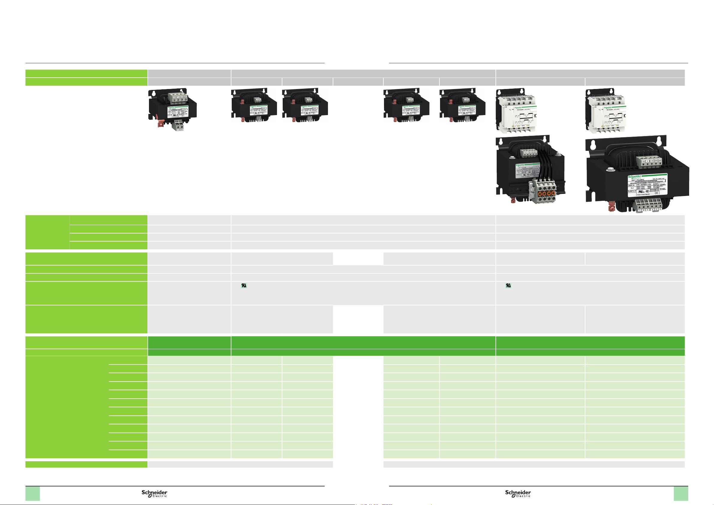
Selection guide
Modicon Transformer
Single phase transformer 230 to 400 Vac,
25 to 2500 VA
Modicon ABT7, ABL6
Input voltage 230 Vac, ± 15 V 230 Vac and 400 Vac, ± 15 V 230 Vac and 400 Vac, ± 15 V
Output voltage 24 Vac 12 Vac 24 Vac 115 Vac 230 Vac 2 x 24 Vac 2 x 115 Vac
Connection to
world-wide line
supplies
Applications SELV transformer (Safety Extra Low
Secondary winding Single winding Single winding Double winding
Signalling – –
Certications - e marking
Conformity to standards (1)
Transformer type
United States:
United States:
Europe:
Europe:
120 V (in phase-to-neutral) – – –
240 V (in phase-to-phase) – 2-phase (L1-L2) connection 2-phase (L1-L2) connection
230 V (in phase-to-neutral) Single-phase (N-L1) connection Single-phase (N-L1) connection Single-phase (N-L1) connection
400 V (in phase-to-phase) – 2-phase (L1-L2) connection 2-phase (L1-L2) connection
Voltage)
- EAC
- EN 61558-2-6
- EN 61558-1
- EN 62041
Transformers 230 VAC, Single
SELV transformer (Safety Extra Low Voltage) Isolation transformer SELV transformer (Safety Extra Low Voltage) Isolation transformer
Presence of input voltage by LED (up to 320 VA)
- C us
- e marking
- UL (506)
- EAC
- EN 61558-2-6
- UL 506
- EN 61558-1
- EN 62041
- EN 61558-2-4
- EN 61558-1
- EN 62041
- C us,
- e marking
- UL (506)
- EAC
- EN 61558-2-6
- UL 506
- EN 61558-1
- EN 62041
Transformers 230/400 VAC, Single winding: ABL6 Transformers 230/400 VAC, Double winding: ABT7PDU
winding: ABT7ESM
Operating temperature 40 °C 50 °C 60 °C
Nominal power
25 VA
40 VA
63 VA
100 VA
160 VA
250 VA
320 VA
400 VA
630 VA
1 000 VA
1 600 VA
2 500 VA
ABL6TS02J ABL6TS02B ABL6TS02G ABL6TS02U ABT7PDU002G
ABT7ESM004B ABL6TS04J ABL6TS04B ABL6TS04G ABL6TS04U ABT7PDU004B ABT7PDU004G
ABT7ESM006B ABL6TS06J ABL6TS06B ABL6TS06G ABL6TS06U ABT7PDU006B ABT7PDU006G
ABT7ESM010B ABL6TS10J ABL6TS10B ABL6TS10G ABL6TS10U ABT7PDU010B ABT7PDU010G
ABT7ESM016B ABL6TS16J ABL6TS16B ABL6TS16G ABL6TS16U ABT7PDU016B ABT7PDU016G
ABT7ESM025B ABL6TS25J ABL6TS25B ABL6TS25G ABL6TS25U ABT7PDU025B ABT7PDU025G
ABT7ESM032B ABT7PDU032B ABT7PDU032G
ABT7ESM040B ABL6TS40B ABL6TS40G ABL6TS40U ABT7PDU040B ABT7PDU040G
ABL6TS63B ABL6TS63G ABL6TS63U ABT7PDU063B ABT7PDU063G
ABL6TS100B ABL6TS100G ABL6TS100U ABT7PDU100B ABT7PDU100G
ABL6TS160B ABL6TS160G ABL6TS160U ABT7PDU160B ABT7PDU160G
ABL6TS250B ABL6TS250G ABL6TS250U ABT7PDU250B ABT7PDU250G
- EN 61558-2-4
- UL 506
- EN 61558-1
- EN 62041
Pages 4 4
(1) Consult detail on conformity to standards for each reference in the product data sheet, click on product reference to open it.
Note: Phaseo Transformers shown in this document are identied as Modicon as they will undergo a future brand change.
All other product documentation will reference Phaseo until the brand change occurs.
2 22 3

Presentation,
1
description
Modicon Transformer
Single phase transformers 230 to 400 Vac,
25 to 2500 VA
Modicon ABT7, ABL6
Presentation
Modicon ABT7/ABL6 single-phase transformers are designed to supply control
circuits in electrical equipment from a 230 Vac or 400 Vac supply (depending on the
model) at 50 or 60 Hz. ± 15 V connectors at the primary ensure adaptation to the
actual values of the supply networks to which they are connected.
Transformers 230 V, Single winding: ABT7ESM
The single-winding transformers are primarily designed for repetitive applications
and oers the following as standard:
b 230 Vac ± 15 V input voltage
b 24 Vac output voltage
b Panel mounting using 4 screws
b Operating temperature of 40°C (104°F)
Transformers 230/400 V, Single winding: ABL6
The single-winding transformers are designed for standard applications:
b 230 V/400 Vac ± 15 V input voltage
b 12 V, 24 V, 115 V or 230 Vac output voltage
b Panel mounting, using 4 screws (or clip-on 5 rail-mounting option available
depending on the model)
b Operating temperature of 50°C (122°F)
b cURus certications
Transformers 230/400 V, Double winding: ABT7PDU
Transformers with double winding feature an innovative design and oer high-level
characteristics (depending on the model) such as:
b 230 V/400 Vac ± 15 V input voltage
b 2 x 115 V or 2 x 24 Vac output voltage
b Clip-on 5 rail mounting (depending on the model) or panel mounting (using 4
screws)
b Series or parallel connection of secondary winding and grounding via internal
jumpers
b LED indicator
b Operating temperature of 60°C (140°F)
b cURus certication
Those components are concealed behind a plastic cover making it easier to
integrate the Modicon transformers in control cabinets.
Protection
The transformers can be protected against short-circuits by means of fuses or
thermal-magnetic circuit-breakers mounted on the secondary.
For operation in compliance with UL standards, short-circuit protection must be
achieved using fuses (UL approved) mounted on the primary.
Where the control circuit is isolated from the ground (IT system), a leakage detector
will indicate any accidental ground faults.
ABT7
ABT7PDU002p…7PDU032p
4
Description
1 Mounted using 4 screws or, depending on the model for ABT7PDU types, by
clipping on a 35 mm (1.37 in) 5 rail
2 Screw terminals with ± 15 V connectors for connection of the AC input voltage
3 Clip-on marker tag or self-adhesive marker tag holder AR1SB3
4 LED (green) indicating presence of input voltage (depending on ABT7PDU types)
5 Access to the jumpers for selecting the secondary connection (opened using a
screwdriver)
6 Windows (depending on ABT7PDU types) for viewing the connection via jumpers
2
3
4
5
6
7
of the:
- 0 V to ground (J1 jumper)
- Series connection, totally freeing up the “customer” secondary wiring capacity
(J3 jumper)
- Parallel connection, totally freeing up the “customer” secondary wiring
capacity (J2 and J4 jumpers)
7 Screw terminals for connection of the AC output voltage
Note: Phaseo Transformers shown in this document are identied as Modicon as they will
undergo a future brand change. All other product documentation will reference Phaseo until the
brand change occurs.

10 000
1000
10
200
100
10 10080 1000 10 000
63 VA
160 VA
250 VA
400 VA
630 VA
1000 VA
1600 VA
2500 VA
40 VA
25 VA
100 VA
320 VA
Selection
Modicon Transformer
Single phase transformers 230 to 400 Vac,
25 to 2500 VA
Modicon ABT7, ABL6
Selection
Modicon ABT7/ABL6 transformers are characterized by the apparent nominal power
they can supply continuously. However, they are also designed to supply, when
necessary, signicantly higher powers, such as contactor inrush peaks.
Contactor inrush peaks can reach 10 to 20 times the required holding current. This
leads to the transformer being oversized in relation to the continuous power it has to
supply. The transformer must be sized so that the voltage drop at its terminals,
caused by the inrush, remains with the permissible limits for the contactor to close
properly.
The two power values that need to be taken into account to determine which
transformer rating to use are therefore:
b The continuous power the transformer has to supply
b The maximum inrush power it has to provide
In practice, only the sum of the holding currents and the contactor inrush current
need to be considered.
For ABL6 transformers, the graph below can be used to select the appropriate rating
according to these two currents. This gives a maximum voltage drop of 5% at the
moment of inrush, compatible with correct operation of the entire installation.
However, these transformers have been designed for continuous operation at
nominal load and at an ambient temperature of 50°C (122 °F). A reduction in the
ambient temperature may uprate the transformer, which, in some cases, allows a
lower rating to be used.
The graph below has been drawn up for ambient temperatures of 35…50°C
(95…122 °F)
Holding current (VA)
Operation at 35°C (95 °F)
Operation at 50°C (122 °F)
Example: A device with a total holding current of 200 VA and inrush current of the
contactor of 700 VA can be supplied by a 630 VA transformer if it is used at an
ambient temperature of 50°C (122 °F). A 400 VA transformer is sucient if the
ambient temperature is 35°C (95 °F).
Inrush current (VA)
5

Selection of protection
Modicon Transformer
Single phase transformers 230 to 400 Vac,
25 to 2500 VA
Modicon ABT7, ABL6
Recommended protection for the primary
Protection on the primary by fuse or thermal magnetic circuit breaker
Transformer 230 Vac single-phase input voltage
Reference
ABT7ESM004B 40 VA 0.3 A 0.25 A GV2RT03 0.5 A D curve (3)
ABT7ESM006B 63 VA 0.4 A 0.5 A GV2RT03 0.5 A D curve (3)
ABT7ESM010B 100 VA 0.5 A 0.5 A GV2RT04 0.5 A D curve
ABT7ESM016B 160 VA 1 A 1 A GV2RT05 1 A D curve
ABT7ESM025B 250 VA 1.25 A 2 A GV2RT06 2 A D curve (3)
ABT7ESM032B 320 VA 1.5 A 2 A GV2RT06 2 A D curve (3)
ABT7ESM040B 400 VA 2 A 2 A GV2RT07 3 A D curve (3)
Recommended protection for the secondary
Protection on the secondary by fuses of thermal circuit breaker
Transformer 24 Vac secondary
Reference Power gG fuse (1) aM fuses TeSys
ABT7ESM004B 40 VA 1 A 1 A GB2CD07 2 A C curve
ABT7ESM006B 63 VA 2 A 2 A GB2CD08 3 A C curve
ABT7ESM010B 100 VA 4 A 4 A GB2CD09 4 A C curve
ABT7ESM016B 160 VA 6 A 6 A GB2CD12 6 A C curve
ABT7ESM025B 250 VA 10 A 10 A GB2CD16 10 A C curve
ABT7ESM032B 320 VA 12 A 12 A GB2CD20 16 A C curve
ABT7ESM040B 400 VA 16 A 16 A GB2CD21 16 A C curve
Power
MDL fuses
UL Listed (1)
aM fuses TeSys
GV2RT
GB2 (IEC/
CSA-c/US)
Acti9 IC60 (2)
Acti9 IC60 (2)
(1) For operation in compliance with UL
(2) Check on our website for the exact reference. For installation in North America, please select
a UL489 compliant circuit breaker
(3) Protection on the secondary is necessary
6

Selection of protection
(continued)
Modicon Transformer
Single phase transformers 230 to 400 Vac,
25 to 2500 VA
Modicon ABT7, ABL6
Recommended protection for the primary
Protection on the primary by fuse or thermal magnetic circuit breaker
Transformer 230 Vac single-phase 400 Vac single-phase
Reference
ABT7PDU002G 25 VA
ABT7PDU004B/G 40 VA
ABT7PDU006B/G 63 VA
ABT7PDU010B/G 100 VA
ABT7PDU016B/G 160 VA
ABT7PDU025B/G 250 VA
ABT7PDU032B/G 320 VA
ABT7PDU040B/G 400 VA
ABT7PDU063B/G 630 VA
ABT7PDU100B/G 1000 VA
ABT7PDU160B/G 1600 VA
ABT7PDU250B/G 2500 VA – 12 A – – 25 A D curve (3)
Power
MDL
fuses UL
listed (1)
0.2 A
0.3 A
0.5 A
0.5 A
1 A
1.25 A
1.5 A
2 A
3 A
5 A
8 A
aM
TeSys
fuses
GB2 (IEC/
CSA-c/US)
0.25 A – – –
0.25 A GB2DB05 GV2RT03 0.5 A D curve (3)
0.5 A GB2DB06 GV2RT04 0.5 A D curve (3)
0.5 A GB2DB06 GV2RT04 1 A D curve (3)
1 A GB2DB07 GV2RT05 1 A D curve (3)
2 A GB2DB07 GV2RT06 2 A D curve (3)
2 A GB2DB07 GV2RT07 2 A D curve
2 A GB2DB09 GV2RT07 3 A D curve (3)
4 A GB2DB12
(3)
6 A GB2DB16
(3)
8 A GB2DB21
(3)
TeSys
GV2RT
GV2RT08 6 A D curve (3)
GV2RT10 10 A D curve (3)
GV2RT14 16 A D curve (3)
Acti9 IC60 (2) MDL
fuses UL
Listed (1)
0.25 A
0.25 A
0.25 A
0.3 A
0.5 A
0.75 A
1 A
1.25 A
2 A
3 A
4 A
7 A
aM
fuses
0.16 A – – –
0.16 A – – –
0.25 A – – –
0.5 A GB2DB05 GV2RT03 0.5 A D curve
0.5 A GB2DB06 GV2RT04 1 A D curve
1 A GB2DB06 GV2RT05 1 A D curve
1 A GB2DB06 GV2RT05 1 A D curve
2 A (3) GB2DB07 GV2RT06 2 A D curve
2 A GB2DB09
4 A (3) GB2DB12
6 A (3) GB2DB14
8 A (3) GB2DB21
TeSys
GB2 (IEC/
CSA-c/US)
(3)
(3)
(3)
(3)
TeSys
GV2RT
– 4 A D curve (3)
– 6 A D curve (3)
GV2RT10 10 A D curve (3)
GV2RT14 16 A D curve (3)
Acti9 IC60 (2)
Recommanded protection for the secondary
Protection on the secondary by fuses of thermal circuit breaker
Transformer 24 Vac secondary 48 Vac secondary
Reference Power gG fuse
(1)
ABT7PDU004B 40 VA 2 A 2 A GB2CD07 2 A C curve 1 A 1 A GB2CD06 1 A C curve
ABT7PDU006B 63 VA 2 A 2 A GB2CD08 3 A C curve 1 A 1 A GB2CD06 1 A C curve
ABT7PDU010B 100 VA 4 A 4 A GB2CD09 4 A C curve 2 A 2 A GB2CD07 2 A C curve
ABT7PDU016B 160 VA 6 A 6 A GB2CD12 6 A C curve 2 A 2 A GB2CD08 3 A C curve
ABT7PDU025B 250 VA 10 A 10 A GB2CD16 10 A C curve 4 A 4 A GB2CD10 6 A C curve
ABT7PDU032B 320 VA 12 A 12 A GB2CD20 16 A C curve 6 A 6 A GB2CD12 10 A C curve
ABT7PDU040B 400 VA 16 A 16 A GB2CD21 16 A C curve 8 A 8 A GB2CD14 10 A C curve
ABT7TDU063B 630 VA 25 A 25 A – 25 A C curve 12 A 12 A GB2CD20 16 A C curve
ABT7TDU100B 1000 VA 40 A 40 A – 40 A C curve 20 A 20 A GB2CD22 20 A C curve
ABT7TDU160B 1600 VA 63 A 63 A – 63 A C curve 32 A 32 A – 32 A C curve
ABT7TDU250B 2500 VA 100 A 100 A – – 50 A 50 A – 50 A C curve
Transformer 115 Vac secondary 230 Vac secondary
Reference Power gG fuse
(1)
ABT7PDU002G 25 VA – 0.25 A – – – 0.16 A – –
ABT7PDU004G 40 VA 0.5 A 0.5 A GB2CD05 – – 0.25 A – –
ABT7PDU006G 63 VA 0.5 A 0.5 A GB2CD05 0.5 A C curve – 0.25 A – –
ABT7PDU010G 100 VA 1 A 1 A GB2CD05 1 A C curve 0.5 A 0.5 A GB2CD06 0.5 A C curve
ABT7PDU016G 160 VA 1 A 1 A GB2CD06 2 A C curve 0.5 A 0.5 A GB2CD07 1 A C curve
ABT7PDU025G 250 VA 2 A 2 A GB2CD06 2 A C curve 1 A 1 A GB2CD07 1 A C curve
ABT7PDU032G 320 VA 2 A 2 A GB2CD07 3 A C curve 1 A 1 A GB2CD08 2 A C curve
ABT7PDU040G 400 VA 4 A 4 A GB2CD07 4 A C curve 2 A 2 A GB2CD08 2 A C curve
ABT7TDU063G 630 VA 4 A 4 A GB2CD09 4 A C curve 2 A 2 A GB2CD07 2 A C curve
ABT7TDU100G 1000 VA 8 A 8 A GB2CD14 10 A C curve 4 A 4 A GB2CD09 4 A C curve
ABT7TDU160G 1600 VA 12 A 12 A GB2CD20 16 A C curve 6 A 6 A GB2CD12 6 A C curve
ABT7TDU250G 2500 VA 20 A 20 A GB2CD22 20 A C curve 10 A 10 A GB2CD16 10 A C curve
(1) For operation in compliance with UL.
(2) Check on our website for the exact reference. For installation in North America. please select a UL489 compliant circuit breaker.
(3) Protection on the secondary is necessary.
aM
fuses
aM
fuses
TeSys
GB2 (IEC/
CSA-c/
US)
TeSys
GB2 (IEC/
CSA-c/US)
Acti9 IC60 (2) gG fuse
Acti9 IC60
(2)
(1)
gG fuse
(1)
aM
fuses
aM
fuses
TeSys
GB2 (IEC/
CSA-c/US)
TeSys
GB2 (IEC/
CSA-c/US)
Acti9 IC60 (2)
Acti9 IC60 (2)
7

Selection of protection
(continued)
Modicon Transformer
Single phase transformers 230 to 400 Vac,
25 to 2500 VA
Modicon ABT7, ABL6
Recommended protection for the primary
Protection on the primary by fuse or thermal magnetic circuit breaker
Transformer 230 Vac single-phase input voltage 400 Vac single-phase input voltage
Reference
ABL6TS02J 25 VA 0.18 A 0.16 A – – – 0.25 A 0.16 A – – –
ABL6TS04J 40 VA 0.25 A 0.25 A GB2DB05 GV2RT03 0.5 A D curve (3) 0.25 A 0.16 A – – –
ABL6TS06J 63 VA 0.37 A 0.5 A GB2DB05 GV2RT03 0.5 A D curve (3) 0.25 A 0.25 A – – –
ABL6TS10J 100 VA 0.5 A 0.5 A GB2DB06 GV2RT04 1 A D curve (3) 0.3 A 0.5 A GB2DB05 GV2RT03 0.5 A D curve
ABL6TS16J 160 VA 1 A 1 A GB2DB07 GV2RT05 2 A D curve (3) 0.5 A 0.5 A GB2DB06 GV2RT04 1 A D curve
ABL6TS25J 250 VA 1.25 A 2 A GB2DB07 GV2RT06 2 A D curve (3) 0.75 A 1 A GB2DB06 GV2RT05 1 A D curve
Recommanded protection for the secondary
Protection on the secondary by fuses of thermal circuit breaker
Transformer 12 Vac secondary
Reference Power gG fuse
ABL6TS02J 25 VA 2 A 2 A GB2CD07 2 A C curve
ABL6TS04J 40 VA 4 A 4 A GB2CD08 3 A C curve
ABL6TS06J 63 VA 6 A 6 A GB2CD10 6 A C curve
ABL6TS10J 100 VA 8 A 8 A GB2CD14 10 A C curve
ABL6TS16J 160 VA 12 A 12 A GB2CD20 16 A C curve
ABL6TS25J 250 VA 20 A 20 A GB2CD22 20 A C curve
Recommended protection for the primary
Protection on the primary by fuse or thermal magnetic circuit breaker
Transformer 230 Vac single-phase input voltage 400 Vac single-phase input voltage
Reference
ABL6TS02B 25 VA 0.18 A 0.16 A – – – 0.25 A 0.16 A – – –
ABL6TS04B 40 VA 0.25 A 0.25 A GB2DB05 GV2RT03 0.5 A D curve (3) 0.25 A 0.16 A – – –
ABL6TS06B 63 VA 0.37 A 0.5 A GB2DB05 GV2RT03 0.5 A D curve (3) 0.25 A 0.25 A – – –
ABL6TS10B 100 VA 0.5 A 0.5 A GB2DB05 GV2RT04 1 A D curve (3) 0.3 A 0.5 A GB2DB05 GV2RT03 0.5 A D curve
ABL6TS16B 160 VA 1 A 1 A GB2DB06 GV2RT05 2 A D curve (3) 0.5 A 0.5 A GB2DB06 GV2RT04 1 A D curve
ABL6TS25B 250 VA 1.25 A 2 A GB2DB07 GV2RT06 2 A D curve (3) 0.75 A 1 A GB2DB06 GV2RT05 1 A D curve
ABL6TS40B 400 VA 2 A 2 A GB2DB09 GV2RT07 3 A D curve (3) 1.5 A 1 A GB2DB07 GV2RT06 2 A D curve
ABL6TS63B 630 VA 3 A 4 A GB2DB12 GV2RT08 6 A D curve (3) 2.5 A 2 A GB2DB09 GV2RT07 3 A D curve
ABL6TS100B 1000 VA 5 A 6 A GB2DB16 GV2RT10 10 A D curve (3) 3.5 A 4 A GB2DB10 GV2RT08 6 A D curve
ABL6TS160B 1600 VA 8 A 8 A GB2DB20 GV2RT14 16 A D curve (3) 5 A 4 A GB2DB14 GV2RT10 10 A D curve
ABL6TS250B 2500 VA – 12 A GB2DB22 GV2RT16 20 A D curve (3) 7.5 A 8 A (3) GB2DB20 GV2RT14 10 A D curve
Power
Power
MDL fuses
UL listed (1)
(1)
MDL fuses
UL listed (1)
aM
fuses
aM
fuses
TeSys
GB2 (IEC/
CSA-c/
US)
aM
fuses
TeSys
GB2 (IEC/
CSA-c/
US)
TeSys
GV2RT
TeSys
GB2 (IEC/
CSA-c/US)
TeSys
GV2RT
Acti9 IC60 (2) MDL fuses
UL Listed (1)
Acti9 IC60 (2)
Acti9 IC60 (2) MDL fuses
UL Listed (1)
aM
fuses
aM
fuses
TeSys
GB2 (IEC/
CSA-c/US)
TeSys
GB2 (IEC/
CSA-c/US)
TeSys
GV2RT
TeSys
GV2RT
Acti9 IC60
(2)
Acti9 IC60
(2)
Recommanded protection for the secondary
Protection on the secondary by fuses of thermal circuit breaker
Transformer 24 Vac secondary
Reference Power gG fuse
(1)
ABL6TS02B 25 VA 1 A 1 A GB2CD06 1 A C curve
ABL6TS04B 40 VA 1 A 1 A GB2CD07 2 A C curve
ABL6TS06B 63 VA 2 A 2 A GB2CD08 3 A C curve
ABL6TS10B 100 VA 4 A 4 A GB2CD09 4 A C curve
ABL6TS16B 160 VA 6 A 6 A GB2CD12 6 A C curve
ABL6TS25B 250 VA 10 A 10 A GB2CD16 10 A C curve
ABL6TS40B 400 VA 16 A 16 A GB2CD21 16 A C curve
ABL6TS63B 630 VA 25 A 25 A – 25 A C curve
ABL6TS100B 1000 VA 40 A 40 A – 40 A C curve
ABL6TS160B 1600 VA 63 A 63 A – 63 A C curve
ABL6TS250B 2500 VA 100 A 100 A – –
(1) For operation in compliance with UL
(2)Check on our website for the exact reference. For installation in North America, please select a UL489 compliant circuit breaker
(3) Protection on the secondary is necessary
8
aM
fuses
TeSys
GB2 (IEC/
CSA-c/US)
Acti9 IC60
(2)

Selection of protection
(continued)
Modicon Transformer
Single phase transformers 230 to 400 Vac,
25 to 2500 VA
Modicon ABT7, ABL6
Recommended protection for the primary
Protection on the primary by fuse or thermal magnetic circuit breaker
Transformer 230 Vac single-phase input voltage 400 Vac single-phase input voltage
Reference
ABL6TS02G 25 VA 0.18 A 0.16 A – – – 0.25 A 0.16 A – – –
ABL6TS04G 40 VA 0.25 A 0.25 A GB2DB05 GV2RT03 0.5 A D curve (3) 0.25 A 0.16 A – – –
ABL6TS06G 63 VA 0.37 A 0.5 A GB2DB06 GV2RT03 0.5 A D curve (3) 0.25 A 0.25 A – – –
ABL6TS10G 100 VA 0.5 A 0.5 A GB2DB06 GV2RT04 1 A D curve (3) 0.3 A 0.5 A GB2DB05 GV2RT03 0.5 A D curve
ABL6TS16G 160 VA 1 A 1 A GB2DB07 GV2RT05 1 A D curve (3) 0.5 A 0.5 A GB2DB06 GV2RT04 1 A D curve
ABL6TS25G 250 VA 1.25 A 2 A GB2DB07 GV2RT06 2 A D curve (3) 0.75 A 1 A GB2DB06 GV2RT05 1 A D curve
ABL6TS40G 400 VA 2 A 2 A GB2DB09 GV2RT07 4 A D curve (3) 1.5 A 2 A (3) GB2DB07 GV2RT06 2 A D curve
ABL6TS63G 630 VA 3 A 4 A GB2DB12 GV2RT08 6 A D curve (3) 2.5 A 4 A (3) GB2DB08 GV2RT07 3 A D curve
ABL6TS100G 1000 VA 5 A 6 A GB2DB16 GV2RT10 10 A D curve (3) 3.5 A 4 A GB2DB10 GV2RT08 6 A D curve
ABL6TS160G 1600 VA 8 A 8 A GB2DB16 GV2RT14 10 A D curve (3) 5 A 4 A GB2DB12 GV2RT10 6 A D curve
ABL6TS250G 2500 VA – 2 5 A (3) – – – – 10 A (3) GB2DB22 GV2RT16 (3) –
Recommanded protection for the secondary
Protection on the secondary by fuses of thermal circuit breaker
Transformer 115 Vac secondary
Reference Power gG fuse
ABL6TS02G 25 VA – 0.25 A – –
ABL6TS04G 40 VA 0.5 A 0.5 A – –
ABL6TS06G 63 VA 0.5 A 0.5 A GB2CD05 0.5 A C curve
ABL6TS10G 100 VA 1 A 1 A GB2CD06 1 A C curve
ABL6TS16G 160 VA 1 A 1 A GB2CD07 2 A C curve
ABL6TS25G 250 VA 2 A 2 A GB2CD07 2 A C curve
ABL6TS40G 400 VA 4 A 4 A GB2CD09 4 A C curve
ABL6TS63G 630 VA 6 A 6 A GB2CD12 6 A C curve
ABL6TS100G 1000 VA 8 A 8 A GB2CD16 10 A C curve
ABL6TS160G 1600 VA 12 A 12 A GB2CD21 16 A C curve
ABL6TS250G 2500 VA 20 A 20 A GB2CD22 20 A C curve
Recommended protection for the primary
Protection on the primary by fuse or thermal magnetic circuit breaker
Transformer 230 Vac single-phase input voltage 400 Vac single-phase input voltage
Reference
ABL6TS02U 25 VA 0.18 A 0.16 A – – – 0.25 A 0.16 A – – –
ABL6TS04U 40 VA 0.25 A 0.25 A GB2DB05 GV2RT03 0.5 A D curve (3) 0.25 A 0.16 A – – –
ABL6TS06U 63 VA 0.37 A 0.5 A GB2DB05 GV2RT03 0.5 A D curve (3) 0.25 A 0.25 A – – –
ABL6TS10U 100 VA 0.5 A 0.5 A GB2DB05 GV2RT04 1 A D curve (3) 0.3 A 0.5 A GB2DB05 GV2RT03 0.5 A D curve
ABL6TS16U 160 VA 1 A 1 A GB2DB06 GV2RT05 2 A D curve (3) 0.5 A 0.5 A GB2DB06 GV2RT04 1 A D curve
ABL6TS25U 250 VA 1.25 A 2 A GB2DB07 GV2RT06 2 A D curve (3) 0.75 A 1 A GB2DB06 GV2RT05 1 A D curve
ABL6TS40U 400 VA 2 A 2 A GB2DB09 GV2RT07 3 A D curve (3) 1.5 A 2 A (3) GB2DB07 GV2RT06 2 A D curve
ABL6TS63U 630 VA 3 A 4 A GB2DB14 GV2RT10 (3) 10 A D curve (3) 2.5 A 4 A (3) GB2DB10 GV2RT08 (3) 4 A D curve
ABL6TS100U 1000 VA 5 A 6 A GB2DB20 GV2RT14 (3) 10 A D curve (3) 5 A (3) 4 A GB2DB12 GV2RT10 (3) 6 A D curve
ABL6TS160U 1600 VA 8 A 8 A GB2DB20 GV2RT14 16 A D curve (3) 5 A (3) 4 A GB2DB14 GV2RT10 6 A D curve
ABL6TS250U 2500 VA – 16 A (3) – – – – 10 A (3) GB2DB22 GV2RT16 (3) 16 A D curve
Recommanded protection for the secondary
Protection on the secondary by fuses of thermal circuit breaker
Transformer 230 Vac secondary
Reference Power gG fuse
ABL6TS02U 25 VA – 0.16 A – –
ABL6TS04U 40 VA – 0.16 A – –
ABL6TS06U 63 VA – 0.25 A – –
ABL6TS10U 100 VA 0.5 A 0.5 A GB2CD05 0.5 A C curve
ABL6TS16U 160 VA 0.5 A 0.5 A GB2CD06 1 A C curve
ABL6TS25U 250 VA 1 A 1 A GB2CD06 1 A C curve
ABL6TS40U 400 VA 2 A 2 A GB2CD07 2 A C curve
ABL6TS63U 630 VA 2 A 2 A GB2CD08 3 A C curve
ABL6TS100U 1000 VA 4 A 4 A GB2CD09 4 A C curve
ABL6TS160U 1600 VA 6 A 6 A GB2CD14 6 A C curve
ABL6TS250U 2500 VA 10 A 10 A GB2CD16 10 A C curve
(1) For operation in compliance with UL
(2) Check on our website for the exact reference. For installation in North America, please select a UL489 compliant circuit breaker.
(3) Protection on the secondary is necessary
Power
Power
MDL fuses
UL listed
(1)
(1)
MDL fuses
UL listed
(1)
(1)
aM
fuses
aM
fuses
TeSys GB2
(IEC/CSA-c/
US)
aM
fuses
TeSys GB2
(IEC/CSA-c/
US)
aM
fuses
TeSys GV2RT Acti9 IC60 (2) MDL fuses
TeSys
GB2 (IEC/
CSA-c/US)
TeSys GV2RT Acti9 IC60 (2) MDL fuses
TeSys
GB2 (IEC/
CSA-c/US)
Acti9 IC60 (2)
Acti9 IC60 (2)
UL Listed (1)
UL Listed (1)
aM
fuses
aM
fuses
TeSys GB2
(IEC/CSA-c/
US)
TeSys GB2
(IEC/CSA-c/
US)
TeSys GV2RT Acti9 IC60 (2)
TeSys GV2RT Acti9 IC60 (2)
9

References
ABT7ESM0ppB
ABL6TSppp
Modicon Transformer
Single phase transformers 230 to 400 Vac,
25 to 2500 VA
Modicon ABT7, ABL6
Transformers with single phase (N-L1) or phase-to-phase (L1-L2) connection
Input
voltage
Transformers 230 VAC, Single winding
230 Vac
single phase, (N-L1) or
phase to phase (L1-L2)
connection
± 15 V
Transformers 230/400 VAC, Single winding
230 Vac single phase, (N-L1),
400 Vac phase to phase (L1-L2)
± 15 V
Secondary Nominal
Type Voltage
Single winding 24 V 40 VA ABT7ESM004B 1.020/2.249
Single winding 12 V 25 VA ABL6TS02J 0.700/1.543
24 V 25 VA ABL6TS02B 0.700/1.543
power
63 VA ABT7ESM006B 1.140/2.513
100 VA ABT7ESM010B 1.900/4.189
160 VA ABT7ESM016B 2.720/5.997
250 VA ABT7ESM025B 3.540/7.804
320 VA ABT7ESM032B 4.080/8.995
400 VA ABT7ESM040B 5.100/11.244
40 VA ABL6TS04J 1.200/2.646
63 VA ABL6TS06J 1.600/3.527
100 VA ABL6TS10J 2.100/4.630
160 VA ABL6TS16J 3.200/7.055
250 VA ABL6TS25J 4.400/9.700
40 VA ABL6TS04B 1.200/2.646
63 VA ABL6TS06B 1.600/3.527
100 VA ABL6TS10B 2.100/4.630
160 VA ABL6TS16B 3.200/7.055
250 VA ABL6TS25B 4.400/9.700
400 VA ABL6TS40B 6.500/14.330
630 VA ABL6TS63B 9.800/21.605
1000 VA ABL6TS100B 14.300/31.526
1600 VA ABL6TS160B 19.400/42.770
2500 VA ABL6TS250B 27.400/60.407
Reference Weight
kg/lb
115 V 25 VA ABL6TS02G 0.700/1.543
40 VA ABL6TS04G 1.200/2.646
63 VA ABL6TS06G 1.600/3.527
100 VA ABL6TS10G 2.100/4.630
160 VA ABL6TS16G 3.200/7.055
250 VA ABL6TS25G 4.400/9.700
400 VA ABL6TS40G 6.500/14.330
630 VA ABL6TS63G 9.800/21.605
1000 VA ABL6TS100G 14.300/31.526
1600 VA ABL6TS160G 19.400/42.770
2500 VA ABL6TS250G 27.400/60.407
230 V 25 VA ABL6TS02U 0.700/1.543
40 VA ABL6TS04U 1.200/2.646
63 VA ABL6TS06U 1.600/3.527
100 VA ABL6TS10U 2.100/4.630
160 VA ABL6TS16U 3.200/7.055
250 VA ABL6TS25U 4.400/9.700
400 VA ABL6TS40U 6.500/14.330
630 VA ABL6TS63U 9.800/21.605
1000 VA ABL6TS100U 14.300/31.526
1600 VA ABL6TS160U 19.400/42.770
2500 VA ABL6TS250U 27.400/60.407
10

References (continued)
Transformers with single phase (N-L1) or phase-to-phase (L1-L2) connection
Input
voltage
Transformers 230/400 V, Double winding
With cover, connected by internal jumpers with LED indicators
230 Vac single phase, (N-L1),
400 Vac phase to phase (L1-L2)
± 15 V
ABT7PDU002p…032p
Modicon Transformer
Single phase transformers 230 to 400 Vac,
25 to 2500 VA
Modicon ABT7, ABL6
Secondary Nominal
Type Voltage
Double winding 2 x 24 V 40 VA ABT7PDU004B 1.400/3.086
2 x 115 V 25 VA ABT7PDU002G 1.100/2.425
power
63 VA ABT7PDU006B 1.940/4.277
100 VA ABT7PDU010B 2.860/6.305
160 VA ABT7PDU016B 4.400/9.700
250 VA ABT7PDU025B 5.600/12.346
320 VA ABT7PDU032B 7.100/15.653
40 VA ABT7PDU004G 1.400/3.086
63 VA ABT7PDU006G 1.940/4.277
100 VA ABT7PDU010G 2.860/6.305
160 VA ABT7PDU016G 4.400/9.700
250 VA ABT7PDU025G 5.600/12.346
320 VA ABT7PDU032G 7.100/15.653
Reference Weight
kg/lb
ABT7PDU040p…250p
ABL6AM0p
Without cover, connected by external jumpers
230 Vac single phase, (N-L1),
400 Vac phase to phase (L1-L2)
± 15 V
Double winding 2 x 24 V 400 VA ABT7PDU040B 7.400/16.314
630 VA ABT7PDU063B 7.900/17.418
1000 VA ABT7PDU100B 14.000/30.865
1600 VA ABT7PDU160B 20.000/44.092
2500 VA ABT7PDU250B 28.000/61.729
2 x 115 V 400 VA ABT7PDU040G 7.400/16.314
630 VA ABT7PDU063G 7.900/17.418
1000 VA ABT7PDU100G 14.000/30.865
1600 VA ABT7PDU160G 20.000/44.092
2500 VA ABT7PDU250G 28.000/61.729
Separate parts for ABT7 and ABL6
Designation Use on transformers Order in
Plates for mounting
on 5 rail
ABL6TS02J, ABL6TS02B,
ABL6TS02G, ABL6TS02U
ABT7ESM004B, ABT7ESM006B,
ABL6TS04J, ABL6TS04B,
ABL6TS04G, ABL6TS04U
ABL6TS06J, ABL6TS06B,
ABL6TS06G, ABL6TS06U
ABT7ESM010B,ABL6TS10J,
ABL6TS10B, ABL6TS10G,
ABL6TS10U
ABT7ESM016B 5 ABL6AM04 0.085/0.187
multiples of
5 ABL6AM00 0.045/0.099
5 ABL6AM01 0.050/0.110
5 ABL6AM02 0.055/0.121
5 ABL6AM03 0.065/0.143
Unit reference Weight
kg/lb
Self-adhesive marker tag
holder
20 x 10 mm (0.78 x 0.39 in)
– 50 AR1SB3 0.001/0.002
Replacement parts for ABT7 and ABL6
Designation Use on Reference Weight
Pack of 10 jumpers ABT7PDU double-winding transformer ABT7JMP01 0.010/0.022
kg/lb
11

Index
Modicon Transformer
Single phase transformers 230 to 400 Vac,
25 to 2500 VA
Modicon ABT7, ABL6
A
ABL6AM00
ABL6AM01
ABL6AM02
ABL6AM03
ABL6AM04
ABL6TS02B
ABL6TS02G
ABL6TS02J
ABL6TS02U
ABL6TS04B
ABL6TS04G
ABL6TS04J
ABL6TS04U
ABL6TS06B
ABL6TS06G
ABL6TS06J
ABL6TS06U
ABL6TS100B
ABL6TS100G
ABL6TS100U
ABL6TS10B
ABL6TS10G
ABL6TS10J
ABL6TS10U
ABL6TS160B
ABL6TS160G
ABL6TS160U
ABL6TS16B
ABL6TS16G
ABL6TS16J
ABL6TS16U
ABL6TS250B
ABL6TS250G
ABL6TS250U
ABL6TS25B
ABL6TS25G
ABL6TS25J
ABL6TS25U
ABL6TS40B
ABL6TS40G
ABL6TS40U
ABL6TS63B
ABL6TS63G
ABL6TS63U
ABT7ESM004B
ABT7ESM006B
ABT7ESM010B
ABT7ESM016B
ABT7ESM025B
ABT7ESM032B
ABT7ESM040B
ABT7JMP01
ABT7PDU002G
ABT7PDU004B
ABT7PDU004G
ABT7PDU006B
ABT7PDU006G
ABT7PDU010B
ABT7PDU010G
ABT7PDU016B
ABT7PDU016G
ABT7PDU025B
ABT7PDU025G
ABT7PDU032B
11
ABT7PDU032G
11
ABT7PDU040B
11
ABT7PDU040G
11
ABT7PDU063B
11
ABT7PDU063G
10
ABT7PDU100B
10
ABT7PDU100G
10
ABT7PDU160B
10
ABT7PDU160G
10
ABT7PDU250B
10
ABT7PDU250G
10
ABT7TDU063B
10
ABT7TDU063G
10
ABT7TDU100B
10
ABT7TDU100G
10
ABT7TDU160B
10
ABT7TDU160G
10
ABT7TDU250B
10
ABT7TDU250G
10
AR1SB3
10
10
10
10
10
10
10
10
10
10
10
10
10
10
10
10
10
10
10
10
10
10
10
10
10
10
10
10
10
10
10
11
11
11
11
11
11
11
11
11
11
11
11
11
11
11
11
11
11
11
11
11
11
11
11
7
7
7
7
7
7
7
7
11
12

Learn more about our products at
www.schneider-electric.com
The information provided in this documentation contains general descriptions and/or technical characteristics of the performance of the
products contained herein. This documentation is not intended as a substitute for and is not to be used for determining suitability or reliability
of these products for specic user applications. It is the duty of any such user or integrator to perform the appropriate and complete risk
analysis, evaluation and testing of the products with respect to the relevant specic application or use thereof. Neither Schneider Electric
nor any of its aliates or subsidiaries shall be responsible or liable for misuse of the information contained herein.
Design: Schneider Electric
Photos: Schneider Electric
Sch
neider Electric Industries SAS
Head Oce
35, rue Joseph Monier - CS 30323
F-92500 Rueil-Malmaison Cedex
France
DIA3ED2170403EN
October 2020 - V3.0
 Loading...