


Installation Instructions
Specifications
Actuator Inputs
Control Signal
Power Input
Connections
Actuator Outputs
Electrical
Position Feedback Voltage
(proportional or floating only)
Mechanical
Timing
Travel
Manual Override
See Table-1 thru 4 for actuator mod-
els and control types.
See Table-1 thru 4. All 24 Vac circuits
are Class 2. All circuits 30 Vac and
above are Class 1.
3 ft (91 cm) appliance or plenum ca-
bles, enclosure accepts 1/2” (13 mm)
conduit connector. For M20 Metric
conduit, use AM-756 adaptor.
For voltage ranges, the feedback
signal is the same range as the input
signal. The 4 to 20 mA current range
and floating actuators have a 2 to 10
Vdc feedback signal. The feedback
signal can supply up to 0.5 mA to
operate up to four additional slave
actuators.
See Figure-1 to Figure-4.
93° nominal.
Allows positioning of damper or valve
using manual crank.
Environment
Ambient Temperature Limits
Shipping & Storage
Operating
Humidity
Location
Agency Listings
UL 873
CUL
European Community
Australia
-40 to 160°F (-40 to 71°C).
-22 to 140°F (-30 to 60°C).
15 to 95% RH, non-condensing.
NEMA 1. NEMA 2, UL Type 2 (IEC
IP54) with customer supplied water
tight conduit connectors. Enclosure is
air plenum rated.
Underwriters Laboratories (File
#E9429 Category Temperature-Indi-
cating and Regulating Equipment).
UL Listed for use in Canada by
Underwriters Laboratories. Canadian
Standards C22.2 No. 24-93.
EMC Directive (89/336/EEC). Low
Voltage Directive (72/23/EEC). This
product fits in Installation Category
(Overvoltage Category) II per EN
61010-1.
This product meets requirements to
bear the RCM according to the terms
specified by the Communications
Authority under the Radiocommuni-
cations Act 1992.
RA/DA Jumper
Permits reverse acting/direct acting
control (MS4D models only).
Table 1. 30 in-lb (3.4 N-m) Spring Return CCW Actuators (Viewed from cover side)
Part Number Control Signal Voltage Wiring System
50/60 Hz
VA W W
MA4D-7033-000
MA4D-7033-100 Plenum Cable
2
MA4D-7030-000
Position
SPST
MA4D-7031-000
24 VAC
+/-20%
or 20-30
Vdc
120 Vac ±
10%
50/60 Hz
230 Va ±
10%
Appliance Wire
5.1 3.6 0.14 1.3
7.8 5.0 — 2.5
Appliance Wire
7.2 5.2 — 2.4
50/60 Hz
MF4D-7033-000
MF4D-7033-100 Plenum Cable
MS4D-7033-000
MS4D-7033-100 Plenum Cable
MS4D-7033-020
MS4D-7033-120 Plenum Cable
MS4D-7033-030
MS4D-7033-130 Plenum Cable
MS4D-7033-050
MS4D-7033-150 Plenum Cable
MS4D-7033-060
MS4D-7033-160 Plenum Cable
a Timing was measured with no load applied to actuator.
b 4 to 20 mAdc with field-installed 500 ohm resistor.
Floating
2 to 10 Vdcb
Proportional
0 to 3 Vdc
Proportional
6 to 9 Vdc
Proportional
0 to 10 Vdc
Proportional
4 to 20 mAdc
Proportional
24 Vac
+/-20%
or 20-30
Vdc
Appliance Wire
Appliance Wire
Appliance Wire
Appliance Wire
Appliance Wire
Appliance Wire
6.8 4.2 0.15 1.9
6.1 3.4 0.12 1.4
Actuator Power Input
Running Holding
DC
50/60 Hz
Amps
Approximate Timinga in
Sec. @ 70 °F (21 °C)
Pow-
ered
Spring Return
(CCW)
56 23
85 21
November, 2018 tc © 2018 Schneider Elect ric. All r ights res erved. A ll trade marks are o wned by Schneider Ele ctric Ind ustries S AS or its af filiat ed companies.
Document Number: F-27170-7
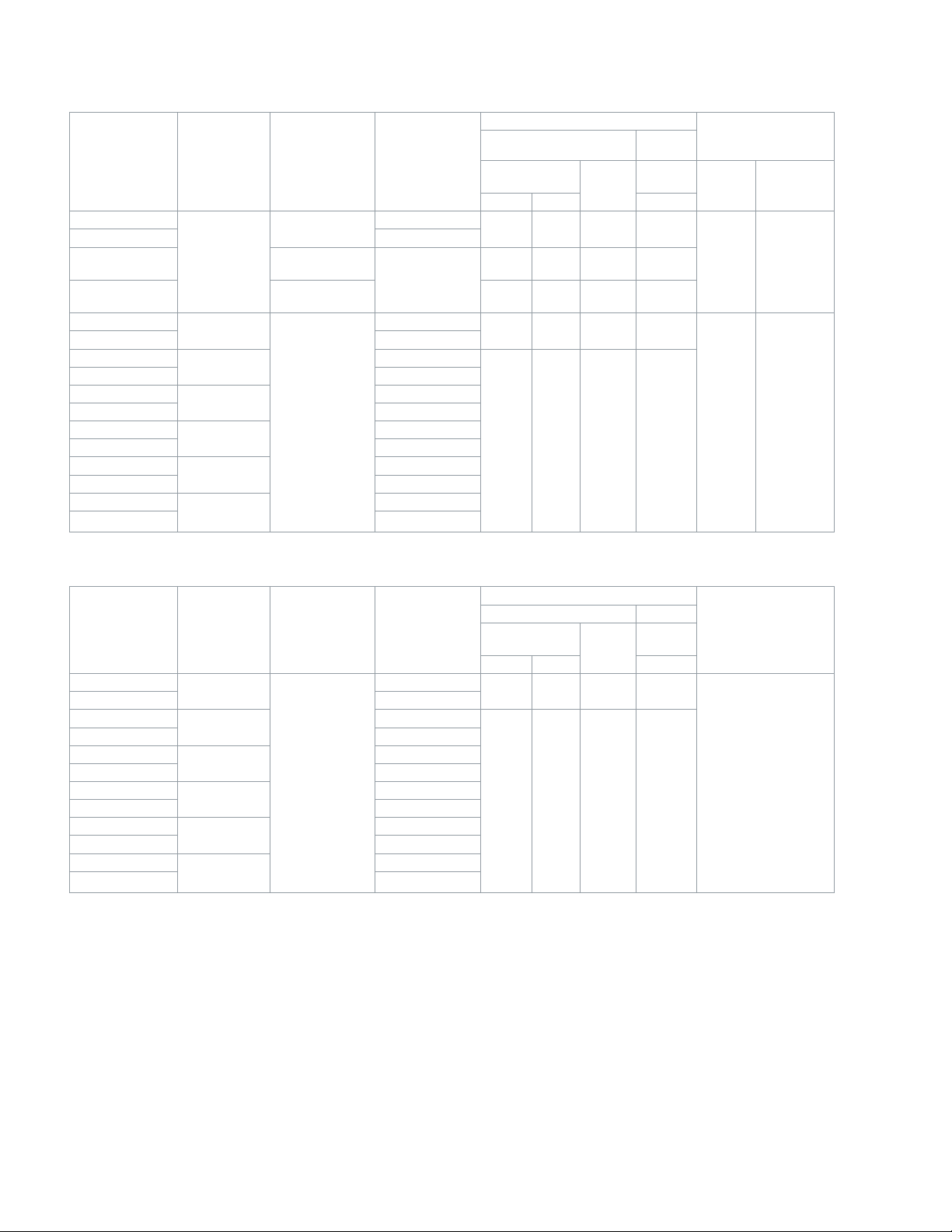
Table 2. 30 in-lb (3.4 N-m) Spring Return CW Actuators (Viewed from cover side)
Part Number
Control
Signal
Voltage Wiring System
50/60 Hz
VA W W
MA4D-8033-000
MA4D-8033-100 Plenum Cable
MA4D-8030-000
2
Position
SPST
MA4D-8031-000
MF4D-8033-000
MF4D-8033-100 Plenum Cable
MS4D-8033-000
MS4D-8033-100 Plenum Cable
MS4D-8033-020
MS4D-8033-120 Plenum Cable
MS4D-8033-030
MS4D-8033-130 Plenum Cable
MS4D-8033-050
MS4D-8033-150 Plenum Cable
MS4D-8033-060
MS4D-8033-160 Plenum Cable
a Timing was measured with no load applied to actuator.
b 4 to 20 mAdc with field-installed 500 ohm resistor.
Floating
2 to 10 Vdcb
Proportional
0 to 3 Vdc
Proportional
6 to 9 Vdc
Proportional
0 to 10 Vdc
Proportional
4 to 20 mAdc
Proportional
24 VAC +/-20%
or 20-30 Vdc
120 Vac ± 10%
50/60 Hz
230 Va ± 10%
50/60 Hz
24 Vac +/-20%
or 20-30 Vdc
Appliance Wire
Appliance Wire
Appliance Wire
Appliance Wire
Appliance Wire
Appliance Wire
Appliance Wire
Appliance Wire
5.1 3.6 0.14 1.3
7.8 5.0 — 2.5
7.2 5.2 — 2.4
6.8 4.2 0.15 1.9
6.1 3.4 0.12 1.4
Actuator Power Input Approximate Timing
Running Holding
DC
50/60
Hz
Amps
in Sec. @ 70 °F (21
°C)
Pow-
ered
Spring Re-
turn (CW)
56 23
85 21
Installation Instructions
a
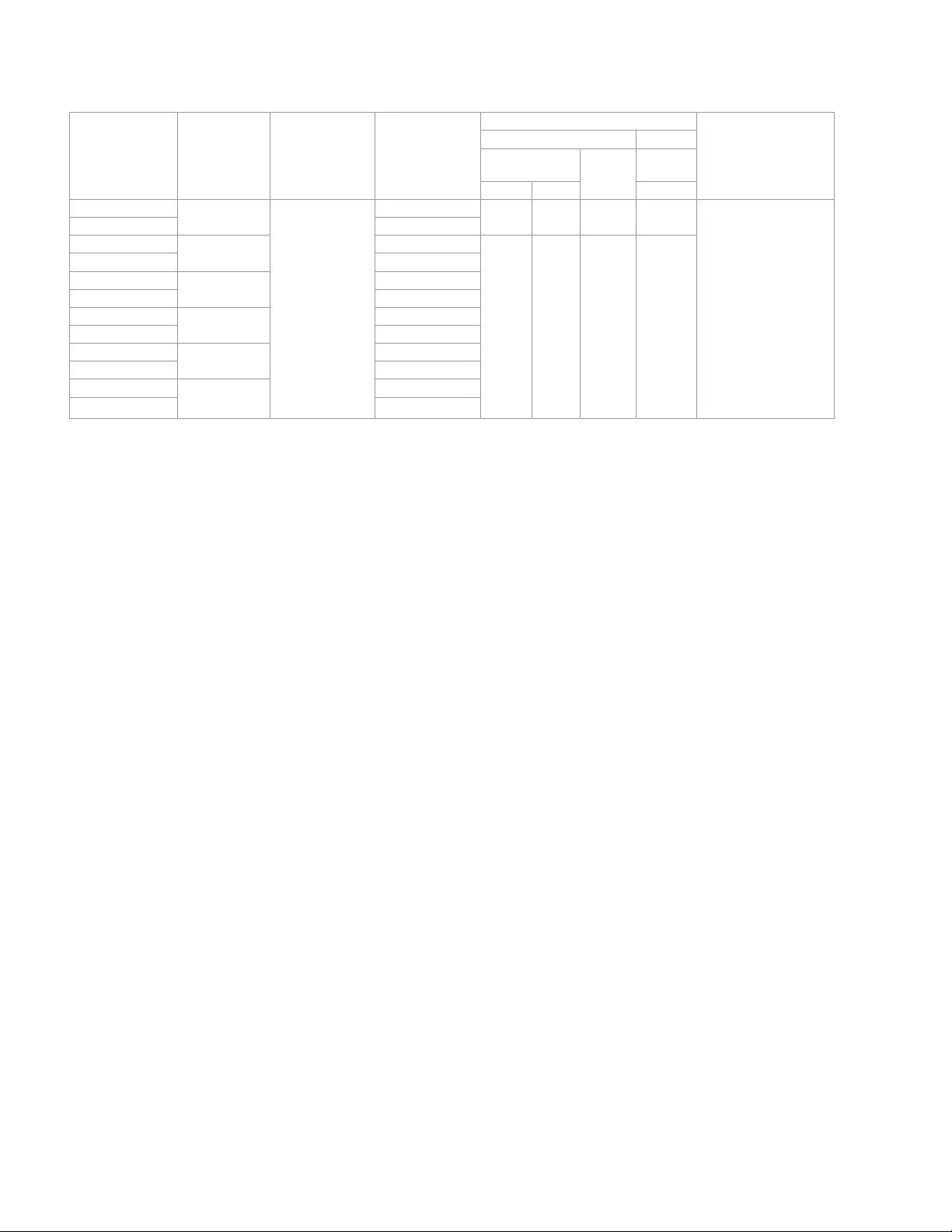
Table 3. Non-Spring Return 35 in-lb (4 N-m) Actuators.
Part Number
MF4D-6043-000
MF4D-6043-100 Plenum Cable
MS4D-6043-000
MS4D-6043-100 Plenum Cable
MS4D-6043-020
MS4D-6043-120 Plenum Cable
MS4D-6043-030
MS4D-6043-130 Plenum Cable
MS4D-6043-050
MS4D-6043-150 Plenum Cable
MS4D-6043-060
MS4D-6043-160 Plenum Cable
a Timing was measured with no load applied to actuator.
b 4 to 20 mAdc with field-installed 500 ohm resistor.
Control
Signal
Floating
2 to 10 Vdcb
Proportional
0 to 3 Vdc
Proportional
6 to 9 Vdc
Proportional
0 to 10 Vdc
Proportional
4 to 20 mAdc
Proportional
Voltage Wiring System
Appliance Wire
Appliance Wire
Appliance Wire
24 Vac +/-20%
or 20-30 Vdc
Appliance Wire
Appliance Wire
Appliance Wire
Actuator Power Input
Running Holding
50/60 Hz
VA W W
DC
Amps
4.4 2.7 0.1 1.7
4.2 2.2 0.08 1.2
50/60
Hz
Approximate Timinga
in Sec. @ 70 °F (21
°C)
85
© 2018 Schneider Elect ric. All r ights res erved. A ll trade marks are o wned by Schneider Ele ctric Ind ustries SAS or its af filiat ed companies. Novemb er, 2018 tc
Docume nt Number : F-27170-7
Installation Instructions
Table 4. Non-Spring Return 70 in-lb (8 N-m) Actuators.
Part Number
MF4D-6083-000
MF4D-6083-100 Plenum Cable
MS4D-6083-000
MS4D-6083-100 Plenum Cable
MS4D-6083-020
MS4D-6083-120 Plenum Cable
MS4D-6083-030
MS4D-6083-130 Plenum Cable
MS4D-6083-050
MS4D-6083-150 Plenum Cable
MS4D-6083-060
MS4D-6083-160 Plenum Cable
a Timing was measured with no load applied to actuator.
b 4 to 20 mAdc with field-installed 500 ohm resistor.
Control
Signal
Floating
2 to 10 Vdcb
Proportional
0 to 3 Vdc
Proportional
6 to 9 Vdc
Proportional
0 to 10 Vdc
Proportional
4 to 20 mAdc
Proportional
Voltage Wiring System
Appliance Wire
Appliance Wire
Appliance Wire
24 Vac +/-20%
or 20-30 Vdc
Appliance Wire
Appliance Wire
Appliance Wire
Actuator Power Input
Running Holding
50/60 Hz
VA W W
5.9 3.6 0.13 1.6
5.2 2.7 0.10 1.4
DC
Amps
50/60
Hz
Approximate Timing
in Sec. @ 70 °F (21
°C)
85
a
Ball Valve Close-Off Pressures: For close-off pressure ratings on Schneider Electric VB2000 ball valves, consult Schneider Electric VB2000 Ball Valve Assemblies Ball Valve Body/Linkage Selection Guide F-27086.
Accessories
AM-763 1/8” Hexcrank for manual override
AM-756 Metric Conduit Adapter M20 x 1.5 to 1/2” NPT
AM-771 Crank Arm and bracket kit
AM-772 Bracket for reverse mounting
AM-714 Weathershield Kit
MS4D-xxx3-xxx
AM-703 Input rescaling module, adjust signals to 2-10 Vac, zero and span adjust
AM-704 Interface, pulse width modulation (PWM)
AM-705 Positioner (NEMA 4 housing)
AM-706 Min and/or manual positioner for flush panel mount
AM-708 500 Ω resistor for 4 to 20 mA control signal
November, 2018 tc © 2018 Schneider Elect ric. All r ights res erved. A ll trade marks are o wned by Schneider Ele ctric Ind ustries S AS or its af filiat ed companies.
Document Number: F-27170-7


Installation Instructions
Installation
Inspect the package for damage. If damaged, notify the appropriate carrier immediately. If undamaged, open the package and
inspect the device for obvious damage. Return damaged products.
Requirements
• Job wiring diagrams
• Appropriate accessories
• Installer must be a qualified, experienced technician
• 1/8” hex allen wrench (not provided)
• #8 Torx screwdriver (not provided)
• #8 sheet metal screws (2) (not provided)
• Appropriate drill bits (not provided
Precautions
Warning:
• Electrical shock hazard! Disconnect the power supply (line power) before installation to prevent electric shock and equipment
damage.
• Make all connections in accordance with the job wiring diagram and in accordance with national and local electrical codes.
Use copper conductors only.
• Floating and Proportional Models: These products contain a half-wave rectifier power supply. They must not be powered with
transformers that are used to power other devices utilizing non-isolated full-wave rectifier power supplies. Refer to EN-206,
Guidelines For Powering Devices From A Common Transformer, F-26363 for detailedinformation.
Caution:
• Avoid electrical noise interference. Do not install near large contactors, electrical machinery, or welding equipment.
• Manual override to be used only when power is not applied to unit.
• When operating manual override (observe position indicator), back off 5° from full extended mechanical stop to ensure proper
release.
Federal Communications Commission (FCC)
Note: This equipment has been tested and found to comply with the limits for a Class B digital device, pursuant to Part 15 of the
FCC Rules. These limits are designed to provide reasonable protection against harmful interference in residential installations.
This equipment generates, uses, and can radiate radio frequency energy and may cause harmful interference if not installed and
used in accordance with the instructions. Even when instructions are followed, there is no guarantee that interference will not
occur in a particular setting—Which can be determined by turning the equipment off and on—the user is encouraged to try to
correct the interference by one or more of the following measures:
• Reorient or relocate the receiving antenna.
• Increase the separation between the equipment and receiver.
• Connect the equipment to an outlet on a circuit different from that to which the receiver is connected.
• Consult the dealer or an experienced radio/television technician for help.
Canadian Department of Communications (DOC)
Note: This Class B digital apparatus meets all requirements of the Canadian Interference- Causing Equipment Regulations.
Cet appareil numerique de la classe B respecte toutes les exigences du Reglement sur le material broilleur du Canada.
European Standard EN 55022
Note: This is a Class B digital (European Classification) product. In a domestic environment this product may cause radio interference in which case the user may be required to take adequate measures.
Location
Caution: Avoid locations where excessive moisture, corrosive fumes, vibration, or explosive vapors are present.
November, 2018 tc © 2018 Schneider Elect ric. All r ights res erved. A ll trade marks are o wned by Schneider Ele ctric Ind ustries S AS or its af filiat ed companies.
Document Number: F-27170-7


Installation Instructions
Ball Valve Mounting
Installation of Mx4D-xxxx-xxx Actuators on 1/2” to 3” Schneider Electric VB2000 Ball Valves
Install the actuator onto the ball valve according to Figure-16.
Note: If space constraints do not allow the actuator to be installed in the standard position, reposition the mounting plate
before mounting the actuator.
The valve should be mounted in a weather-protected area, in a location that is within the ambient temperature limits of the
actuator. The installation of the actuator assembly should provide clearance on all sides to allow for any maintenance that
may be needed (see Figure-13 thru Figure-15).
1. Follow the general piping practices.
2. Apply pipe sealant sparingly to all but the last two threads of a properly threaded, reamed, and cleaned pipe. Make sure
the pipe chips, scale, etc. do not get into the pipe since this material may lodge in the valve seat and prevent proper
operation of the valve. The valve must be piped with an inlet and an outlet.
3. Start the joint hand-threading the pipe into the valve. If the thread alignment feels normal, continue to turn the pipe by
hand as far as it will go.
4. Use a pipe wrench to fully tighten the pipe to the valve.
5. Caution: Do not over-tighten the pipe, which may cause stripped threads. Avoid twisting or crushing the valve while tight-
ening the pipe.
6. Insulate only the valve body and associated piping. Do not insulate the actuator.
7. In chilled or cold water systems where the environment is humid, use a drip pan under the valve to catch condensate.
Caution: The Schneider Electric SmartX Actuator is designed to effectively support its own weight. No load or weight should
be resting on the actuator. Long term damage may occur to the actuator, mounting connection, or valve.
• Do not insulate the actuator/linkage. Doing so will result in excess heat buildup within the actuator.
• For non-steam applications the ball valve assembly must be mounted so the actuator is at least 5° above horizontal
(Figure-13) to ensure that any condensate that forms will not travel into the mounting bracket or actuator.
• On steam applications, the ball valve assembly must be mounted approximately 45° from horizontal (Figure-14).
• Temperature Restrictions: To maintain the maximum ambient temperature 140 °F (60 °C) of the actuator/valve, the
maximum allowable fluid temperature should not exceed the 250 °F(121 °C) ball valve maximum rating.
85˚
Max
0˚
3-7/8" (99 mm) Min.
Clearance
85˚
Max
Figure-13 Acceptable Mounting Orientations.
November, 2018 tc © 2018 Schneider Elect ric. All r ights res erved. A ll trade marks are o wned by Schneider Ele ctric Ind ustries S AS or its af filiat ed companies.
Document Number: F-27170-7


Wiring
Requirements
Control Leads
See Table-5 for power wiring data. Refer to Figure-1 through Figure-8 for typical wiring.
Table-5 Power Wiring.
SmartX
Actuator
Voltage
24 Vac and
22-30 Vdc
Part Number
MA4D-7033
MA4D-8033
MF4D-7033
MF4D-8033
MS4D-7033
MS4D-8033
MF4D-6083
MS4D-6083
MF4D-6043
MS4D-6043
12 AWG 14 AWG 16 AWG 18 AWG 20 AWG 22 AWG
1744
(532)
1308
(399)
1458
(444)
1508
(459)
1710
(521)
2021
(616)
2118
(645)
Maximum Wire Run in ft. (m)
1097
(534)
822
(251))
917
(279)
948
(289)
1075
(328)
1271
(387)
1331
(406)
690
(210)
517
(158)
577
(276)
596
(182)
676
(206)
799
(244)
837
(255)
434
(132)
325
(99)
325
(99)
375
(114)
425
(130)
503
(153)
527
(161)
273
(83)
205
(62))
228
(70)
236
(72)
268
(82)
268
(82)
331
(101)
216
(66)
162
(49)
181
(55)
187
(57)
212
(65)
251
(76)
263
(80)
Installation Instructions
Checkout
With the correct control signals applied, power the actuator. Observe movement of the output shaft to check for proper operation. If a spring return model, removing power should cause the actuator to spring return to its rest position. If problems are
encountered, check the suggestions below.
Note: Check that the transformer(s) are sized properly.
• If a common transformer is used with multiple actuators, make sure that polarity is observed on the secondary. This means
connecting all black wires to one leg of the transformer and all red wires to the other leg of the transformer.
• If multiple transformers are used with one control signal, make sure all black wires are tied together and tied to control
signal negative (-).
• If the controller uses a full-wave power supply and does not provide isolated outputs, a separate transformer is required to
power the actuator.
© 2018 Schneider Elect ric. All r ights res erved. A ll trade marks are o wned by Schneider Ele ctric Ind ustries SAS or its af filiat ed companies. Novemb er, 2018 tc
Docume nt Number : F-27170-7

 Loading...