

Page 1

ILA2K EtherNet/IP
0198441113670 08/2020
ILA2K EtherNet/IP
Integrated Drive
User Guide
Original instructions
08/2020
0198441113670.00
www.schneider-electric.com
Page 2

The information provided in this documentation contains general descriptions and/or technical characteristics of the performance of the products contained herein. This documentation is not intended as a
substitute for and is not to be used for determining suitability or reliability of these products for specific user
applications. It is the duty of any such user or integrator to perform the appropriate and complete risk
analysis, evaluation and testing of the products with respect to the relevant specific application or use
thereof. Neither Schneider Electric nor any of its affiliates or subsidiaries shall be responsible or liable for
misuse of the information contained herein. If you have any suggestions for improvements or amendments
or have found errors in this publication, please notify us.
You agree not to reproduce, other than for your own personal, noncommercial use, all or part of this
document on any medium whatsoever without permission of Schneider Electric, given in writing. You also
agree not to establish any hypertext links to this document or its content. Schneider Electric does not grant
any right or license for the personal and noncommercial use of the document or its content, except for a
non-exclusive license to consult it on an "as is" basis, at your own risk. All other rights are reserved.
All pertinent state, regional, and local safety regulations must be observed when installing and using this
product. For reasons of safety and to help ensure compliance with documented system data, only the
manufacturer should perform repairs to components.
When devices are used for applications with technical safety requirements, the relevant instructions must
be followed.
Failure to use Schneider Electric software or approved software with our hardware products may result in
injury, harm, or improper operating results.
Failure to observe this information can result in injury or equipment damage.
© 2020 Schneider Electric. All rights reserved.
2 0198441113670 08/2020
Page 3

Table of Contents
Safety Information. . . . . . . . . . . . . . . . . . . . . . . . . . . . . . . . . . . . . . . . . . . . 7
About the Book . . . . . . . . . . . . . . . . . . . . . . . . . . . . . . . . . . . . . . . . . . . . . . 9
Chapter 1 Introduction. . . . . . . . . . . . . . . . . . . . . . . . . . . . . . . . . . . . . . . . . . . . . . . . . 13
Overview of Integrated Drive . . . . . . . . . . . . . . . . . . . . . . . . . . . . . . . . . . . . . . . . . . . . . . . . .
Components and Interfaces . . . . . . . . . . . . . . . . . . . . . . . . . . . . . . . . . . . . . . . . . . . . . . . . .
Nameplate . . . . . . . . . . . . . . . . . . . . . . . . . . . . . . . . . . . . . . . . . . . . . . . . . . . . . . . . . . . . . . .
Type Code . . . . . . . . . . . . . . . . . . . . . . . . . . . . . . . . . . . . . . . . . . . . . . . . . . . . . . . . . . . . . . .
Chapter 2 Technical Data . . . . . . . . . . . . . . . . . . . . . . . . . . . . . . . . . . . . . . . . . . . . . . 19
Environmental Conditions . . . . . . . . . . . . . . . . . . . . . . . . . . . . . . . . . . . . . . . . . . . . . . . . . . .
Mechanical Data . . . . . . . . . . . . . . . . . . . . . . . . . . . . . . . . . . . . . . . . . . . . . . . . . . . . . . . . . .
Electrical Data . . . . . . . . . . . . . . . . . . . . . . . . . . . . . . . . . . . . . . . . . . . . . . . . . . . . . . . . . . . .
Electromagnetic Compatibility . . . . . . . . . . . . . . . . . . . . . . . . . . . . . . . . . . . . . . . . . . . . . . . .
Shaft-Specific Data . . . . . . . . . . . . . . . . . . . . . . . . . . . . . . . . . . . . . . . . . . . . . . . . . . . . . . . .
Data for Safety-Related Function STO . . . . . . . . . . . . . . . . . . . . . . . . . . . . . . . . . . . . . . . . .
Conditions for UL 508C and CSA . . . . . . . . . . . . . . . . . . . . . . . . . . . . . . . . . . . . . . . . . . . . .
Chapter 3 Engineering. . . . . . . . . . . . . . . . . . . . . . . . . . . . . . . . . . . . . . . . . . . . . . . . . 31
3.1 Electromagnetic Compatibility (EMC) . . . . . . . . . . . . . . . . . . . . . . . . . . . . . . . . . . . . . . . . . .
Electromagnetic Compatibility (EMC) . . . . . . . . . . . . . . . . . . . . . . . . . . . . . . . . . . . . . . . . . .
3.2 Power Supply . . . . . . . . . . . . . . . . . . . . . . . . . . . . . . . . . . . . . . . . . . . . . . . . . . . . . . . . . . . .
External Power Supply Units. . . . . . . . . . . . . . . . . . . . . . . . . . . . . . . . . . . . . . . . . . . . . . . . .
Wiring Information . . . . . . . . . . . . . . . . . . . . . . . . . . . . . . . . . . . . . . . . . . . . . . . . . . . . . . . . .
3.3 Functional Safety. . . . . . . . . . . . . . . . . . . . . . . . . . . . . . . . . . . . . . . . . . . . . . . . . . . . . . . . . .
Definitions . . . . . . . . . . . . . . . . . . . . . . . . . . . . . . . . . . . . . . . . . . . . . . . . . . . . . . . . . . . . . . .
Function. . . . . . . . . . . . . . . . . . . . . . . . . . . . . . . . . . . . . . . . . . . . . . . . . . . . . . . . . . . . . . . . .
Requirements for Using the Safety-Related Function STO. . . . . . . . . . . . . . . . . . . . . . . . . .
Application Examples STO . . . . . . . . . . . . . . . . . . . . . . . . . . . . . . . . . . . . . . . . . . . . . . . . . .
3.4 EtherNet/IP Fieldbus . . . . . . . . . . . . . . . . . . . . . . . . . . . . . . . . . . . . . . . . . . . . . . . . . . . . . . .
General . . . . . . . . . . . . . . . . . . . . . . . . . . . . . . . . . . . . . . . . . . . . . . . . . . . . . . . . . . . . . . . . .
Messaging and Message Types . . . . . . . . . . . . . . . . . . . . . . . . . . . . . . . . . . . . . . . . . . . . . .
3.5 EtherNet/IP Communication . . . . . . . . . . . . . . . . . . . . . . . . . . . . . . . . . . . . . . . . . . . . . . . . .
Communication via I/O Messages. . . . . . . . . . . . . . . . . . . . . . . . . . . . . . . . . . . . . . . . . . . . .
Output Assembly, Instance 103. . . . . . . . . . . . . . . . . . . . . . . . . . . . . . . . . . . . . . . . . . . . . . .
Input Assembly, Instance 113 . . . . . . . . . . . . . . . . . . . . . . . . . . . . . . . . . . . . . . . . . . . . . . . .
Handshake via the Bit "MT" (Mode Toggle). . . . . . . . . . . . . . . . . . . . . . . . . . . . . . . . . . . . . .
Chapter 4 Installation. . . . . . . . . . . . . . . . . . . . . . . . . . . . . . . . . . . . . . . . . . . . . . . . . . 55
4.1 Mechanical Installation . . . . . . . . . . . . . . . . . . . . . . . . . . . . . . . . . . . . . . . . . . . . . . . . . . . . .
Before Mounting . . . . . . . . . . . . . . . . . . . . . . . . . . . . . . . . . . . . . . . . . . . . . . . . . . . . . . . . . .
Mounting the Integrated Drive . . . . . . . . . . . . . . . . . . . . . . . . . . . . . . . . . . . . . . . . . . . . . . . .
4.2 Electrical Installation . . . . . . . . . . . . . . . . . . . . . . . . . . . . . . . . . . . . . . . . . . . . . . . . . . . . . . .
Overview of Procedure . . . . . . . . . . . . . . . . . . . . . . . . . . . . . . . . . . . . . . . . . . . . . . . . . . . . .
Connection Overview . . . . . . . . . . . . . . . . . . . . . . . . . . . . . . . . . . . . . . . . . . . . . . . . . . . . . .
Connection Via Cable Entry . . . . . . . . . . . . . . . . . . . . . . . . . . . . . . . . . . . . . . . . . . . . . . . . .
Connection Via Industrial Connectors . . . . . . . . . . . . . . . . . . . . . . . . . . . . . . . . . . . . . . . . . .
Connection of CN1 - Vdc Supply Voltage . . . . . . . . . . . . . . . . . . . . . . . . . . . . . . . . . . . . . . .
Connection of CN2 - Fieldbus . . . . . . . . . . . . . . . . . . . . . . . . . . . . . . . . . . . . . . . . . . . . . . . .
Connection of CN3 - RS485 . . . . . . . . . . . . . . . . . . . . . . . . . . . . . . . . . . . . . . . . . . . . . . . . .
Connection of CN4 - 24 V Signal Interface . . . . . . . . . . . . . . . . . . . . . . . . . . . . . . . . . . . . . .
Connection of CN5 - Safety-Related Function STO . . . . . . . . . . . . . . . . . . . . . . . . . . . . . . .
Connection of Accessories for 24 V Signals and Safety-Related Function STO. . . . . . . . . .
4.3 Verifying Installation . . . . . . . . . . . . . . . . . . . . . . . . . . . . . . . . . . . . . . . . . . . . . . . . . . . . . . .
Verifying Installation . . . . . . . . . . . . . . . . . . . . . . . . . . . . . . . . . . . . . . . . . . . . . . . . . . . . . . .
14
15
17
18
20
22
23
26
27
28
29
32
32
34
35
36
37
38
39
40
42
44
45
47
48
49
50
51
53
56
57
58
60
61
63
64
67
68
70
72
74
76
78
80
80
0198441113670 08/2020 3
Page 4

Chapter 5 Commissioning. . . . . . . . . . . . . . . . . . . . . . . . . . . . . . . . . . . . . . . . . . . . . . . 81
5.1 Overview . . . . . . . . . . . . . . . . . . . . . . . . . . . . . . . . . . . . . . . . . . . . . . . . . . . . . . . . . . . . . . . .
General . . . . . . . . . . . . . . . . . . . . . . . . . . . . . . . . . . . . . . . . . . . . . . . . . . . . . . . . . . . . . . . . .
Preparation. . . . . . . . . . . . . . . . . . . . . . . . . . . . . . . . . . . . . . . . . . . . . . . . . . . . . . . . . . . . . . .
5.2 Fieldbus Integration . . . . . . . . . . . . . . . . . . . . . . . . . . . . . . . . . . . . . . . . . . . . . . . . . . . . . . . .
Setting the IP Address . . . . . . . . . . . . . . . . . . . . . . . . . . . . . . . . . . . . . . . . . . . . . . . . . . . . . .
Web Server . . . . . . . . . . . . . . . . . . . . . . . . . . . . . . . . . . . . . . . . . . . . . . . . . . . . . . . . . . . . . .
5.3 Commissioning Procedure. . . . . . . . . . . . . . . . . . . . . . . . . . . . . . . . . . . . . . . . . . . . . . . . . . .
Setting Limit Values . . . . . . . . . . . . . . . . . . . . . . . . . . . . . . . . . . . . . . . . . . . . . . . . . . . . . . . .
Digital Inputs and Digital Outputs. . . . . . . . . . . . . . . . . . . . . . . . . . . . . . . . . . . . . . . . . . . . . .
Verifying the Signals of the Limit Switches . . . . . . . . . . . . . . . . . . . . . . . . . . . . . . . . . . . . . .
Verifying the Safety-Related Function STO . . . . . . . . . . . . . . . . . . . . . . . . . . . . . . . . . . . . . .
Holding Brake (Option). . . . . . . . . . . . . . . . . . . . . . . . . . . . . . . . . . . . . . . . . . . . . . . . . . . . . .
Direction of Movement. . . . . . . . . . . . . . . . . . . . . . . . . . . . . . . . . . . . . . . . . . . . . . . . . . . . . .
Setting Parameters for Encoder. . . . . . . . . . . . . . . . . . . . . . . . . . . . . . . . . . . . . . . . . . . . . . .
5.4 Controller Optimization with Step Response . . . . . . . . . . . . . . . . . . . . . . . . . . . . . . . . . . . . .
Controller Structure . . . . . . . . . . . . . . . . . . . . . . . . . . . . . . . . . . . . . . . . . . . . . . . . . . . . . . . .
Preparation of Optimization . . . . . . . . . . . . . . . . . . . . . . . . . . . . . . . . . . . . . . . . . . . . . . . . . .
Optimizing the Velocity Controller . . . . . . . . . . . . . . . . . . . . . . . . . . . . . . . . . . . . . . . . . . . . .
Verifying and Optimizing the P Gain of the Velocity Controller . . . . . . . . . . . . . . . . . . . . . . .
Optimizing the Position Controller . . . . . . . . . . . . . . . . . . . . . . . . . . . . . . . . . . . . . . . . . . . . .
5.5 Parameter Management . . . . . . . . . . . . . . . . . . . . . . . . . . . . . . . . . . . . . . . . . . . . . . . . . . . .
Resetting the User Parameters . . . . . . . . . . . . . . . . . . . . . . . . . . . . . . . . . . . . . . . . . . . . . . .
Restoring Factory Settings. . . . . . . . . . . . . . . . . . . . . . . . . . . . . . . . . . . . . . . . . . . . . . . . . . .
82
83
85
86
87
90
92
93
94
95
96
97
99
100
102
103
104
105
108
109
111
112
113
Chapter 6 Operation . . . . . . . . . . . . . . . . . . . . . . . . . . . . . . . . . . . . . . . . . . . . . . . . . . . 115
Access Channels . . . . . . . . . . . . . . . . . . . . . . . . . . . . . . . . . . . . . . . . . . . . . . . . . . . . . . . . . .
Movement Range. . . . . . . . . . . . . . . . . . . . . . . . . . . . . . . . . . . . . . . . . . . . . . . . . . . . . . . . . .
Scaling . . . . . . . . . . . . . . . . . . . . . . . . . . . . . . . . . . . . . . . . . . . . . . . . . . . . . . . . . . . . . . . . . .
Parameterization of the Signal Input Functions and the Signal Output Functions. . . . . . . . .
116
117
118
120
Chapter 7 Operating States and Operating Modes. . . . . . . . . . . . . . . . . . . . . . . . . . . . 123
7.1 Operating States . . . . . . . . . . . . . . . . . . . . . . . . . . . . . . . . . . . . . . . . . . . . . . . . . . . . . . . . . .
State Diagram and State Transitions . . . . . . . . . . . . . . . . . . . . . . . . . . . . . . . . . . . . . . . . . . .
Indicating the Operating State via Signal Outputs . . . . . . . . . . . . . . . . . . . . . . . . . . . . . . . . .
Indication of the Operating State via Fieldbus . . . . . . . . . . . . . . . . . . . . . . . . . . . . . . . . . . . .
Changing the Operating State via Signal Inputs . . . . . . . . . . . . . . . . . . . . . . . . . . . . . . . . . .
Changing the Operating State via Fieldbus . . . . . . . . . . . . . . . . . . . . . . . . . . . . . . . . . . . . . .
7.2 Indicating, Starting and Changing an Operating Mode . . . . . . . . . . . . . . . . . . . . . . . . . . . . .
Indicating the Operating Mode. . . . . . . . . . . . . . . . . . . . . . . . . . . . . . . . . . . . . . . . . . . . . . . .
Starting and Changing an Operating Mode . . . . . . . . . . . . . . . . . . . . . . . . . . . . . . . . . . . . . .
7.3 Operating Mode Jog. . . . . . . . . . . . . . . . . . . . . . . . . . . . . . . . . . . . . . . . . . . . . . . . . . . . . . . .
Overview . . . . . . . . . . . . . . . . . . . . . . . . . . . . . . . . . . . . . . . . . . . . . . . . . . . . . . . . . . . . . . . .
Parameterization . . . . . . . . . . . . . . . . . . . . . . . . . . . . . . . . . . . . . . . . . . . . . . . . . . . . . . . . . .
Additional Settings . . . . . . . . . . . . . . . . . . . . . . . . . . . . . . . . . . . . . . . . . . . . . . . . . . . . . . . . .
7.4 Operating Mode Speed Control . . . . . . . . . . . . . . . . . . . . . . . . . . . . . . . . . . . . . . . . . . . . . . .
Overview . . . . . . . . . . . . . . . . . . . . . . . . . . . . . . . . . . . . . . . . . . . . . . . . . . . . . . . . . . . . . . . .
Parameterization . . . . . . . . . . . . . . . . . . . . . . . . . . . . . . . . . . . . . . . . . . . . . . . . . . . . . . . . . .
Additional Settings . . . . . . . . . . . . . . . . . . . . . . . . . . . . . . . . . . . . . . . . . . . . . . . . . . . . . . . . .
7.5 Operating Mode Profile Velocity. . . . . . . . . . . . . . . . . . . . . . . . . . . . . . . . . . . . . . . . . . . . . . .
Overview . . . . . . . . . . . . . . . . . . . . . . . . . . . . . . . . . . . . . . . . . . . . . . . . . . . . . . . . . . . . . . . .
Parameterization . . . . . . . . . . . . . . . . . . . . . . . . . . . . . . . . . . . . . . . . . . . . . . . . . . . . . . . . . .
Additional Settings . . . . . . . . . . . . . . . . . . . . . . . . . . . . . . . . . . . . . . . . . . . . . . . . . . . . . . . . .
7.6 Operating Mode Profile Position . . . . . . . . . . . . . . . . . . . . . . . . . . . . . . . . . . . . . . . . . . . . . .
Overview . . . . . . . . . . . . . . . . . . . . . . . . . . . . . . . . . . . . . . . . . . . . . . . . . . . . . . . . . . . . . . . .
Parameterization . . . . . . . . . . . . . . . . . . . . . . . . . . . . . . . . . . . . . . . . . . . . . . . . . . . . . . . . . .
Additional Settings . . . . . . . . . . . . . . . . . . . . . . . . . . . . . . . . . . . . . . . . . . . . . . . . . . . . . . . . .
124
125
128
129
130
131
132
133
134
135
136
139
140
141
142
143
144
145
146
147
148
149
150
152
153
4 0198441113670 08/2020
Page 5

7.7 Operating Mode Homing . . . . . . . . . . . . . . . . . . . . . . . . . . . . . . . . . . . . . . . . . . . . . . . . . . . .
Overview . . . . . . . . . . . . . . . . . . . . . . . . . . . . . . . . . . . . . . . . . . . . . . . . . . . . . . . . . . . . . . . .
Parameterization . . . . . . . . . . . . . . . . . . . . . . . . . . . . . . . . . . . . . . . . . . . . . . . . . . . . . . . . . .
Reference Movement to a Limit Switch . . . . . . . . . . . . . . . . . . . . . . . . . . . . . . . . . . . . . . . . .
Reference Movement to the Reference Switch in Positive Direction . . . . . . . . . . . . . . . . . .
Reference Movement to the Reference Switch in Negative Direction. . . . . . . . . . . . . . . . . .
Reference Movement to the Index Pulse . . . . . . . . . . . . . . . . . . . . . . . . . . . . . . . . . . . . . . .
Position Setting . . . . . . . . . . . . . . . . . . . . . . . . . . . . . . . . . . . . . . . . . . . . . . . . . . . . . . . . . . .
Additional Settings. . . . . . . . . . . . . . . . . . . . . . . . . . . . . . . . . . . . . . . . . . . . . . . . . . . . . . . . .
154
155
157
160
161
162
163
164
165
Chapter 8 Functions for Operation . . . . . . . . . . . . . . . . . . . . . . . . . . . . . . . . . . . . . . . 167
8.1 Functions for Target Value Processing . . . . . . . . . . . . . . . . . . . . . . . . . . . . . . . . . . . . . . . . .
Motion Profile for the Velocity . . . . . . . . . . . . . . . . . . . . . . . . . . . . . . . . . . . . . . . . . . . . . . . .
Stopping a Movement with Halt. . . . . . . . . . . . . . . . . . . . . . . . . . . . . . . . . . . . . . . . . . . . . . .
Stopping a Movement with Quick Stop . . . . . . . . . . . . . . . . . . . . . . . . . . . . . . . . . . . . . . . . .
Setting a Signal Output via Parameter . . . . . . . . . . . . . . . . . . . . . . . . . . . . . . . . . . . . . . . . .
Position Capture Via Signal Input . . . . . . . . . . . . . . . . . . . . . . . . . . . . . . . . . . . . . . . . . . . . .
8.2 Functions for Monitoring Movements . . . . . . . . . . . . . . . . . . . . . . . . . . . . . . . . . . . . . . . . . .
Hardware Limit Switches. . . . . . . . . . . . . . . . . . . . . . . . . . . . . . . . . . . . . . . . . . . . . . . . . . . .
Reference Switch . . . . . . . . . . . . . . . . . . . . . . . . . . . . . . . . . . . . . . . . . . . . . . . . . . . . . . . . .
Software Limit Switches . . . . . . . . . . . . . . . . . . . . . . . . . . . . . . . . . . . . . . . . . . . . . . . . . . . .
Load-Dependent Position Deviation (Following Error) . . . . . . . . . . . . . . . . . . . . . . . . . . . . .
Standstill Window . . . . . . . . . . . . . . . . . . . . . . . . . . . . . . . . . . . . . . . . . . . . . . . . . . . . . . . . .
8.3 Functions for Monitoring Internal Device Signals . . . . . . . . . . . . . . . . . . . . . . . . . . . . . . . . .
Temperature Monitoring . . . . . . . . . . . . . . . . . . . . . . . . . . . . . . . . . . . . . . . . . . . . . . . . . . . .
Load Monitoring (I2t Monitoring) . . . . . . . . . . . . . . . . . . . . . . . . . . . . . . . . . . . . . . . . . . . . . .
168
169
171
172
174
175
177
178
180
181
183
185
187
188
189
Chapter 9 Examples . . . . . . . . . . . . . . . . . . . . . . . . . . . . . . . . . . . . . . . . . . . . . . . . . . 191
Wiring Example . . . . . . . . . . . . . . . . . . . . . . . . . . . . . . . . . . . . . . . . . . . . . . . . . . . . . . . . . . .
191
Chapter 10 Diagnostics and Troubleshooting . . . . . . . . . . . . . . . . . . . . . . . . . . . . . . . . 193
10.1 Diagnostics via LEDs. . . . . . . . . . . . . . . . . . . . . . . . . . . . . . . . . . . . . . . . . . . . . . . . . . . . . . .
Operating State LEDs . . . . . . . . . . . . . . . . . . . . . . . . . . . . . . . . . . . . . . . . . . . . . . . . . . . . . .
Fieldbus Status LEDs . . . . . . . . . . . . . . . . . . . . . . . . . . . . . . . . . . . . . . . . . . . . . . . . . . . . . .
10.2 Diagnostics via the Fieldbus . . . . . . . . . . . . . . . . . . . . . . . . . . . . . . . . . . . . . . . . . . . . . . . . .
Fieldbus Communication Error Diagnostics . . . . . . . . . . . . . . . . . . . . . . . . . . . . . . . . . . . . .
Most Recent Detected Error - Status Bits . . . . . . . . . . . . . . . . . . . . . . . . . . . . . . . . . . . . . . .
Most Recent Detected Error - Error Code . . . . . . . . . . . . . . . . . . . . . . . . . . . . . . . . . . . . . . .
Error Memory. . . . . . . . . . . . . . . . . . . . . . . . . . . . . . . . . . . . . . . . . . . . . . . . . . . . . . . . . . . . .
Error Response to Incorrect Realtime Ethernet Data . . . . . . . . . . . . . . . . . . . . . . . . . . . . . .
Synchronous Errors. . . . . . . . . . . . . . . . . . . . . . . . . . . . . . . . . . . . . . . . . . . . . . . . . . . . . . . .
10.3 Error Messages . . . . . . . . . . . . . . . . . . . . . . . . . . . . . . . . . . . . . . . . . . . . . . . . . . . . . . . . . . .
Description of Error Messages . . . . . . . . . . . . . . . . . . . . . . . . . . . . . . . . . . . . . . . . . . . . . . .
Table of Error Messages . . . . . . . . . . . . . . . . . . . . . . . . . . . . . . . . . . . . . . . . . . . . . . . . . . . .
194
195
196
197
198
199
201
202
204
205
206
207
208
Chapter 11 Parameters . . . . . . . . . . . . . . . . . . . . . . . . . . . . . . . . . . . . . . . . . . . . . . . . . 213
Representation of the Parameters. . . . . . . . . . . . . . . . . . . . . . . . . . . . . . . . . . . . . . . . . . . . .
List of Parameters . . . . . . . . . . . . . . . . . . . . . . . . . . . . . . . . . . . . . . . . . . . . . . . . . . . . . . . . .
214
216
Chapter 12 Accessories and Spare Parts . . . . . . . . . . . . . . . . . . . . . . . . . . . . . . . . . . . 239
Accessories and Spare Parts . . . . . . . . . . . . . . . . . . . . . . . . . . . . . . . . . . . . . . . . . . . . . . . .
239
Chapter 13 Service, Maintenance, and Disposal . . . . . . . . . . . . . . . . . . . . . . . . . . . . . 241
Service Addresses. . . . . . . . . . . . . . . . . . . . . . . . . . . . . . . . . . . . . . . . . . . . . . . . . . . . . . . . .
Maintenance . . . . . . . . . . . . . . . . . . . . . . . . . . . . . . . . . . . . . . . . . . . . . . . . . . . . . . . . . . . . .
Replacing the Product . . . . . . . . . . . . . . . . . . . . . . . . . . . . . . . . . . . . . . . . . . . . . . . . . . . . . .
Shipping, Storage, Disposal . . . . . . . . . . . . . . . . . . . . . . . . . . . . . . . . . . . . . . . . . . . . . . . . .
Glossary . . . . . . . . . . . . . . . . . . . . . . . . . . . . . . . . . . . . . . . . . . . . . . . . . . . . .
Index . . . . . . . . . . . . . . . . . . . . . . . . . . . . . . . . . . . . . . . . . . . . . . . . . . . . .
242
243
245
246
247
251
0198441113670 08/2020 5
Page 6

6 0198441113670 08/2020
Page 7
Safety Information
Important Information
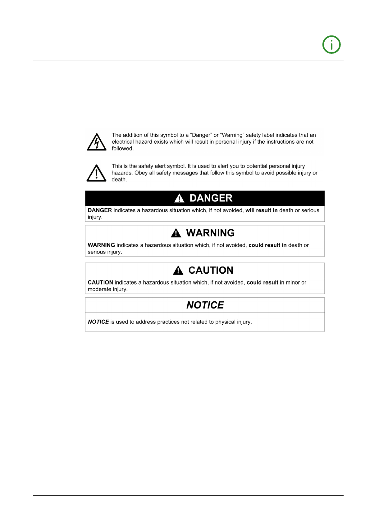
NOTICE
Read these instructions carefully, and look at the equipment to become familiar with the device before
trying to install, operate, service, or maintain it. The following special messages may appear throughout
this documentation or on the equipment to warn of potential hazards or to call attention to information that
clarifies or simplifies a procedure.
PLEASE NOTE
Electrical equipment should be installed, operated, serviced, and maintained only by qualified personnel.
No responsibility is assumed by Schneider Electric for any consequences arising out of the use of this
material.
A qualified person is one who has skills and knowledge related to the construction and operation of
electrical equipment and its installation, and has received safety training to recognize and avoid the
hazards involved.
QUALIFICATION OF PERSONNEL
Only appropriately trained persons who are familiar with and understand the contents of this manual and
all other pertinent product documentation are authorized to work on and with this product. These persons
must have sufficient technical training, knowledge and experience and be able to foresee and detect
potential hazards that may be caused by using the product, by modifying the settings and by the
mechanical, electrical and electronic equipment of the entire system in which the product is used.
The qualified person must be able to detect possible hazards that may arise from parameterization,
modifying parameter values and generally from mechanical, electrical, or electronic equipment.
The qualified person must be familiar with the standards, provisions, and regulations for the prevention of
industrial accidents, which they must observe when designing and implementing the system.
0198441113670 08/2020 7
Page 8

INTENDED USE
The products described in or affected by the present document are, along with software, accessories and
options, motors with an integrated drive. The products are intended for industrial use according to the
instructions, directions, examples, and safety information contained in the present user guide and other
supporting documentation.
The product may only be used in compliance with all applicable safety regulations and directives, the
specified requirements and the technical data.
Prior to using the products, you must perform a risk assessment in view of the planned application. Based
on the results, the appropriate safety-related measures must be implemented.
Since the products are used as components in an overall machine or process, you must ensure the safety
of persons by means of the design of this overall machine or process.
Operate the products only with the specified cables and accessories. Use only genuine accessories and
spare parts.
Any use other than the use explicitly permitted as described herein is prohibited and may result in
unanticipated hazards.
8 0198441113670 08/2020
Page 9

About the Book
At a Glance
Document Scope
This manual describes technical characteristics, installation, commissioning, operation, and maintenance
of the integrated drive ILA2K.
Validity Note
This manual is valid for the standard products listed in the type code, see chapter Type Code
(see page 18)
For product compliance and environmental information (RoHS, REACH, PEP, EOLI, etc.), go to
www.schneider-electric.com/green-premium
The technical characteristics of the devices described in the present document also appear online. To
access the information online, go to the Schneider Electric home page
https://www.se.com/ww/en/download/
The characteristics that are described in the present document should be the same as those characteristics that appear online. In line with our policy of constant improvement, we may revise content over time
to improve clarity and accuracy. If you see a difference between the document and online information, use
the online information as your reference.
Product Related Information
The use and application of the information contained herein require expertise in the design and
programming of automated control systems.
Only you, the user, machine builder or integrator, can be aware of all the conditions and factors present
during installation and setup, operation, repair and maintenance of the machine or process.
You must also consider any applicable standards and/or regulations with respect to grounding of all
equipment. Verify compliance with any safety information, different electrical requirements, and normative
standards that apply to your machine or process in the use of this equipment.
The motor itself generates voltage when the motor shaft is rotated.
.
.
.
DANGER
ELECTRIC SHOCK, EXPLOSION, OR ARC FLASH
Disconnect all power from all equipment including connected devices prior to removing any covers or
doors, or installing or removing any accessories, hardware, cables, or wires.
Place a "Do Not Turn On" or equivalent hazard label on all power switches and lock them in the non-
energized position.
Block the motor shaft to prevent rotation prior to performing any type of work on the drive system.
Replace and secure all covers, accessories, hardware, cables, and wires and confirm that a proper
ground connection exists before applying power to the unit.
Use only the specified voltage when operating this equipment and any associated products.
Failure to follow these instructions will result in death or serious injury.
If the power stage is disabled unintentionally, for example as a result of power outage, errors or functions,
the motor is no longer decelerated in a controlled way. Overload, errors or incorrect use may cause the
holding brake to no longer operate properly and may result in premature wear.
0198441113670 08/2020 9
Page 10
WARNING
UNINTENDED EQUIPMENT OPERATION
Verify that movements without braking effect cannot cause injuries or equipment damage.
Verify the function of the holding brake at regular intervals.
Do not use the holding brake as a service brake.
Do not use the holding brake for safety-related purposes.
Failure to follow these instructions can result in death, serious injury, or equipment damage.
Drive systems may perform unanticipated movements because of incorrect wiring, incorrect settings,
incorrect data or other errors.
WARNING
UNINTENDED MOVEMENT OR MACHINE OPERATION
Carefully install the wiring in accordance with the EMC requirements.
Do not operate the product with undetermined settings and data.
Perform comprehensive commissioning tests that include verification of configuration settings and
data that determine position and movement.
Failure to follow these instructions can result in death, serious injury, or equipment damage.
WARNING
LOSS OF CONTROL
The designer of any control scheme must consider the potential failure modes of control paths and,
for certain critical control functions, provide a means to achieve a safe state during and after a path
failure. Examples of critical control functions are emergency stop and overtravel stop, power outage
and restart.
Separate or redundant control paths must be provided for critical control functions.
System control paths may include communication links. Consideration must be given to the
implications of unanticipated transmission delays or failures of the link.
Observe all accident prevention regulations and local safety guidelines.
Each implementation of this equipment must be individually and thoroughly tested for proper operation
before being placed into service.
Failure to follow these instructions can result in death, serious injury, or equipment damage.
1
1
For additional information, refer to NEMA ICS 1.1 (latest edition), “Safety Guidelines for the Application,
Installation, and Maintenance of Solid State Control” and to NEMA ICS 7.1 (latest edition), “Safety
Standards for Construction and Guide for Selection, Installation and Operation of Adjustable-Speed Drive
Systems” or their equivalent governing your particular location.
Machines, controllers, and related equipment are usually integrated into networks. Unauthorized persons
and malware may gain access to the machine as well as to other devices on the network/fieldbus of the
machine and connected networks via insufficiently secure access to software and networks.
10 0198441113670 08/2020
Page 11

WARNING
UNAUTHORIZED ACCESS TO THE MACHINE VIA SOFTWARE AND NETWORKS
In your risk assessment, take into account all hazards that result from access to and operation on the
network/fieldbus and develop an appropriate cyber security conceptual framework.
Verify that the hardware infrastructure and the software infrastructure into which the machine is
integrated, as well as all organizational measures and rules covering access to this infrastructure, take
into account the results of the hazard and risk analysis.
Implement your cyber security framework according to the best practices and standards of IT security
and cyber security, such as ISO/IEC 27000 series, Common Criteria for Information Technology
Security Evaluation, ISO/IEC 15408, IEC 62351, ISA/IEC 62443, NIST Cybersecurity Framework,
Information Security Forum - Standard of Good Practice for Information Security.
Verify the effectiveness of your IT security and cyber security systems using appropriate, proven
methods.
Failure to follow these instructions can result in death, serious injury, or equipment damage.
Schneider Electric adheres to industry best practices in the development and implementation of control
systems. This includes a "Defense-in-Depth" approach to secure an Industrial Control System. This
approach places the controllers behind one or more firewalls to restrict access to authorized personnel and
protocols only.
WARNING
UNAUTHENTICATED ACCESS AND SUBSEQUENT UNAUTHORIZED MACHINE OPERATION
Evaluate whether your environment or your machines are connected to your critical infrastructure and,
if so, take appropriate steps in terms of prevention, based on Defense-in-Depth, before connecting the
automation system to any network.
Limit the number of devices connected to a network to the minimum necessary.
Isolate your industrial network from other networks inside your company.
Protect any network against unintended access by using firewalls, VPN, or other, proven security
measures.
Monitor activities within your systems.
Prevent subject devices from direct access or direct link by unauthorized parties or unauthenticated
actions.
Prepare a recovery plan including backup of your system and process information.
Failure to follow these instructions can result in death, serious injury, or equipment damage.
For more information on organizational measures and rules covering access to infrastructures, refer to
ISO/IEC 27000 series, Common Criteria for Information Technology Security Evaluation, ISO/IEC 15408,
IEC 62351, ISA/IEC 62443, NIST Cybersecurity Framework, Information Security Forum - Standard of
Good Practice for Information Security.
For reasons of Internet security, TCP/IP forwarding is disabled by default. Therefore, you must manually
enable TCP/IP forwarding. However, doing so may expose your network to possible cyberattacks if you do
not take additional measures to protect your enterprise. In addition, you may be subject to laws and
regulations concerning cybersecurity.
WARNING
UNAUTHENTICATED ACCESS AND SUBSEQUENT NETWORK INTRUSION
Observe and respect any and all pertinent national, regional and local cybersecurity and/or personal
data laws and regulations when enabling TCP/IP forwarding on an industrial network.
Isolate your industrial network from other networks inside your company.
Protect any network against unintended access by using firewalls, VPN, or other, proven security
measures.
Failure to follow these instructions can result in death, serious injury, or equipment damage.
Consult the
Use the latest firmware version. Visit
Schneider Electric Cybersecurity Best Practices
https://www.se.com
for information on firmware updates that may involve Ethernet connections.
for additional information.
or contact your Schneider Electric representative
0198441113670 08/2020 11
Page 12

Terminology Derived from Standards
The technical terms, terminology, symbols and the corresponding descriptions in this manual, or that
appear in or on the products themselves, are generally derived from the terms or definitions of international
standards.
In the area of functional safety systems, drives and general automation, this may include, but is not limited
to, terms such as
,
message
dangerous
Among others, these standards include:
Standard Description
IEC 61131-2:2007 Programmable controllers, part 2: Equipment requirements and tests.
ISO 13849-1:2015 Safety of machinery: Safety related parts of control systems.
EN 61496-1:2013 Safety of machinery: Electro-sensitive protective equipment.
ISO 12100:2010 Safety of machinery - General principles for design - Risk assessment and risk
EN 60204-1:2006 Safety of machinery - Electrical equipment of machines - Part 1: General
ISO 14119:2013 Safety of machinery - Interlocking devices associated with guards - Principles
ISO 13850:2015 Safety of machinery - Emergency stop - Principles for design
IEC 62061:2015 Safety of machinery - Functional safety of safety-related electrical, electronic,
IEC 61508-1:2010 Functional safety of electrical/electronic/programmable electronic safety-
IEC 61508-2:2010 Functional safety of electrical/electronic/programmable electronic safety-
IEC 61508-3:2010 Functional safety of electrical/electronic/programmable electronic safety-
IEC 61784-3:2016 Industrial communication networks - Profiles - Part 3: Functional safety
2006/42/EC Machinery Directive
2014/30/EU Electromagnetic Compatibility Directive
2014/35/EU Low Voltage Directive
safety, safety function, safe state, fault, fault reset, malfunction, failure, error, error
, etc.
General principles for design.
Part 1: General requirements and tests.
reduction
requirements
for design and selection
and electronic programmable control systems
related systems: General requirements.
related systems: Requirements for electrical/electronic/programmable
electronic safety-related systems.
related systems: Software requirements.
fieldbuses - General rules and profile definitions.
In addition, terms used in the present document may tangentially be used as they are derived from other
standards such as:
Standard Description
IEC 60034 series Rotating electrical machines
IEC 61800 series Adjustable speed electrical power drive systems
IEC 61158 series Digital data communications for measurement and control – Fieldbus for use in
Finally, the term
zone of operation
is defined as it is for a
ISO 12100:2010
.
industrial control systems
may be used in conjunction with the description of specific hazards, and
hazard zone
or
danger zone
in the
Machinery Directive (2006/42/EC
) and
NOTE: The aforementioned standards may or may not apply to the specific products cited in the present
documentation. For more information concerning the individual standards applicable to the products
described herein, see the characteristics tables for those product references.
12 0198441113670 08/2020
Page 13

ILA2K EtherNet/IP
Introduction
0198441113670 08/2020
Introduc tion
Chapter 1
Introduction
What Is in This Chapter?
This chapter contains the following topics:
Overview of Integrated Drive 14
Components and Interfaces 15
Nameplate 17
Type Code 18
Topic Page
0198441113670 08/2020 13
Page 14
Introduction
Overview of Integrated Drive
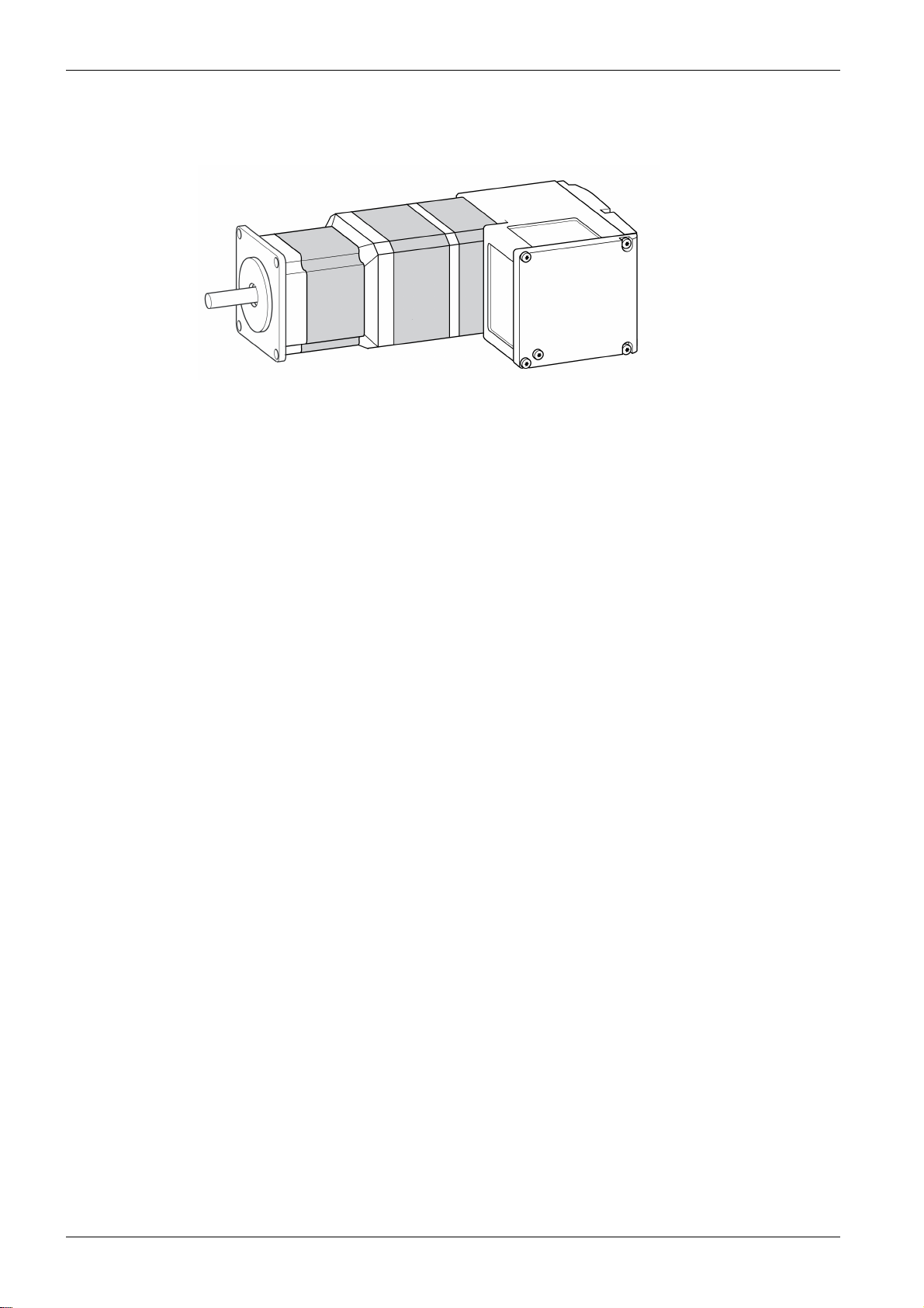
Lexium Integrated Drive
The Lexium integrated drive consists of a servo motor and an integrated drive. The product integrates
interfaces, control electronics, a holding brake (optional) and the power stage.
Minimum wiring as well as a comprehensive portfolio of options and accessories allows you to implement
compact, high-performance drive solutions for a wide range of power requirements.
Features
Overview of some of the features:
Fieldbus interface for EtherNet/IP.
The drive is commissioned via a PC with the commissioning software “Lexium CT” or the fieldbus.
Two Drive Profiles are supported:
“Generic Profile” (CIP)
“Drive Profile Lexium” (manufacturer-specific)
Four digital 24 V signals. Each of these signals can be used as an input or output.
The integrated safety-related function Safe Torque Off (STO) as per IEC 61800-5-2 allows for a stop
with stop category 0 as per IEC 60204-1 without external power contactors.
14
0198441113670 08/2020
Page 15
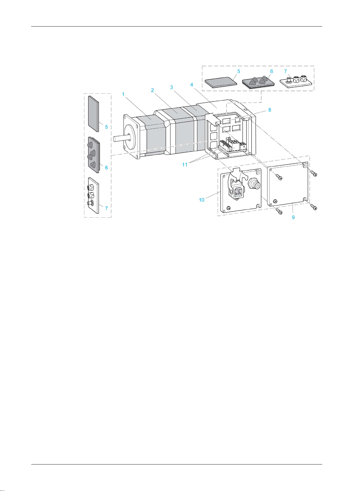
Components and Interfaces
Overview
Introduction
Motor
Electronics
Encoder
1 AC synchronous servo motor
2 Holding brake (optional)
3 Encoder
4 Electronics housing
5 Insert for sealing (accessory)
6 Insert with cable entry (accessory)
7 I/O insert with industrial connectors (accessory)
8 Switches for settings
9 Cover with connector for functional ground, to be removed for installation
10 Cover with industrial connector for Vdc supply voltage and IN/OUT fieldbus connection and with
connector for functional ground (optional)
11 Electrical interfaces
The motor is a brushless AC synchronous servo motor.
The electronic system comprises control electronics and power stage.
The drive can be parameterized and controlled via the fieldbus interface.
Four digital 24 V signals are also available. Each of these signals can be used as an input or output.
The integrated drive features a singleturn or a multiturn encoder, depending on the drive version.
The singleturn encoder has an internal resolution of 32768 increments per revolution.
The scaling of the integrated drive is set to 16384 user-defined units per revolution.
The multiturn encoder covers a range of 4096 motor revolutions.
Holding Brake
The integrated drive is available with an optional integrated holding brake. The holding brake is controlled
automatically.
0198441113670 08/2020 15
Page 16

Introduction
Vdc Supply Voltage
The Vdc supply voltage supplies the control electronics and the power stage.
Fieldbus Interface
The integrated drive features an EtherNet/IP fieldbus interface.
The fieldbus interface is used for parameterizing and controlling the drive. The fieldbus interface allows the
integrated drive to be operated on a fieldbus via a master controller, for example, a logic controller.
Communication Interface RS-485
The RS-485 interface is used for commissioning the drive by means of the commissioning software.
The firmware can be updated via the RS-485 interface. Contact your Schneider Electric service representative for any firmware update.
24 Vdc Signal Interface
Four digital 24 Vdc signals are available. Each of these signals can be used as an input or output.
The 24 Vdc signals are available to the master controller.
16
0198441113670 08/2020
Page 17
Nameplate
Overview
Introduction
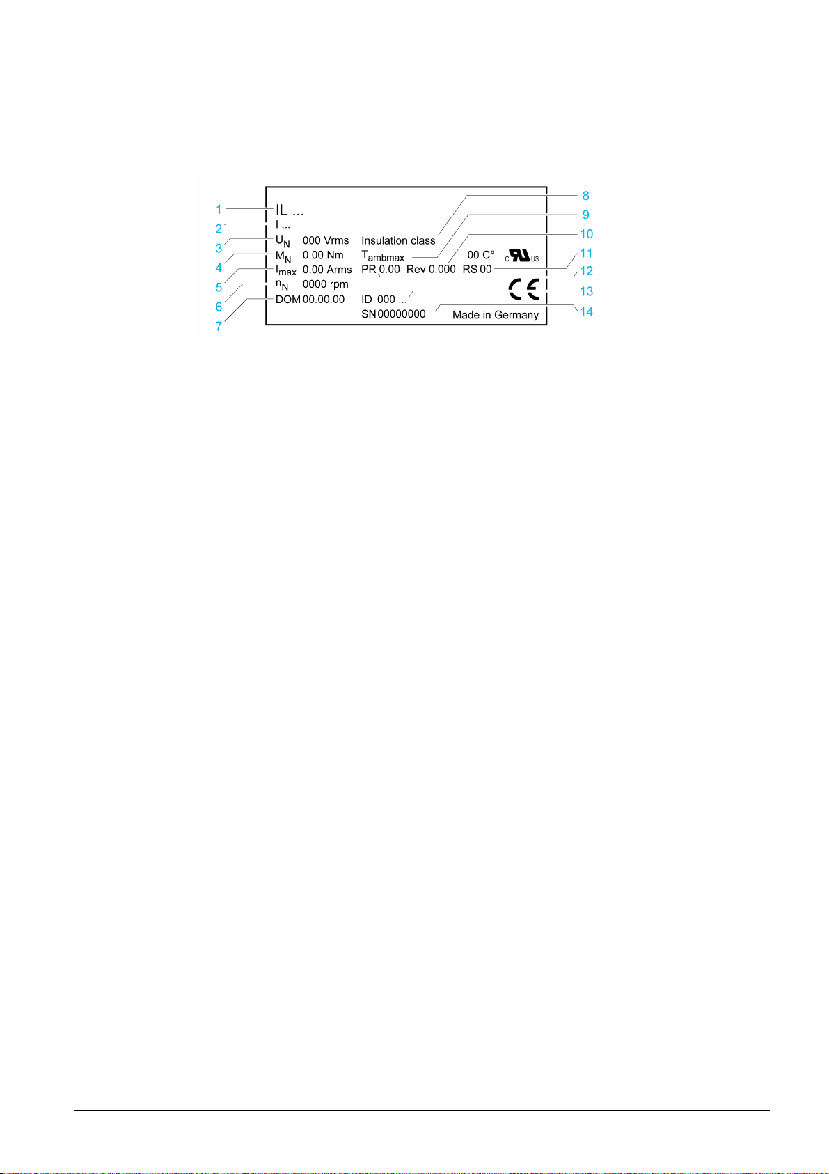
The nameplate contains the following data:
1 Type code
2 Type code (previous)
3 Nominal voltage
4 Nominal torque
5 Maximum input current
6 Nominal speed of rotation
7 Date of manufacture
8 Thermal class
9 Maximum surrounding air temperature
10 Firmware version
11 Hardware version
12 Firmware number
13 Commercial reference
14 Serial number
0198441113670 08/2020 17
Page 18

Introduction
Type Code
Overview
Item 1 2 3 4 5 6 7 8 9 10 11 12 13 14 15
Type code (example) I L A 2 K 5 7 1 P B 1 A 0 • •
Item Meaning
1 ... 3 Product family
ILA = Servo motor
4 Supply voltage
2 = 24 ... 48 Vdc
5 Fieldbus interface
K = EtherNet/IP
6 ... 7 Size
57 = 57 mm
8 Length
1 = 1 stack
2 = 2 stacks
9 Winding
P = Medium speed of rotation/medium torque
T = High speed of rotation/medium torque
10 Connection version
B = Printed circuit board connector
C = Industrial connector
11 Encoder
1 = Servo Singleturn
2 = Servo Multiturn
12 Holding brake
A = Without holding brake
F = With holding brake
13 Gearbox
0 = Without gearbox
14 ... 15 Reserved
If you have questions concerning the type code, contact your Schneider Electric representative.
Designation Customized Version
In the case of a customized version, position 9 of the type code is an "S". The subsequent number defines
the customized version. Example: IL••••••S1234--
Contact your local Schneider Electric service representative if you have questions concerning customized
versions.
18
0198441113670 08/2020
Page 19

ILA2K EtherNet/IP
Technical Data
0198441113670 08/2020
Technical Data
Chapter 2
Technical Data
What Is in This Chapter?
This chapter contains the following topics:
Environmental Conditions 20
Mechanical Data 22
Electrical Data 23
Electromagnetic Compatibility 26
Shaft-Specific Data 27
Data for Safety-Related Function STO 28
Conditions for UL 508C and CSA 29
Topic Page
0198441113670 08/2020 19
Page 20

Technical Data
Environmental Conditions
Environmental Conditions for Operation
Characteristic Unit Value
Chemically active substances as per IEC 607213-3, operation
Ambient temperature (no icing, non-
condensing)
Ambient temperature with current derating of 2 %
per one degree Celsius (per 1.8 degrees
Fahrenheit)
Relative humidity % 15 ... 85
Installation altitude
Installation altitude
conditions are met:
45 °C (113 °F) maximum ambient
temperature
Reduction of the continuous power by 1% per
100 m (328 ft) above 1000 m (3281 ft)
Installation altitude
of the following conditions are met:
40 °C (104 °F) maximum ambient
temperature
Reduction of the continuous power by 1% per
100 m (328 ft) above 1000 m (3281 ft)
(1) Limit values with flanged motor (for example, steel plate 300 x 300x10 mm).
(2) The installation altitude is defined in terms of altitude above mean sea level.
(1)
(1)
(2)
(2)
if all of the following
(2)
above mean sea level if all
°C
(°F)
°C
(°F)
m
(ft)
m
(ft)
m
(ft)
3C1
0...40
(32 ... 104)
40 ... 55
(104 ... 131)
< 1000
(< 3281)
1000 ... 2000
(3281 ... 6562)
2000 ... 3000
(6562 ... 9843)
Environmental Conditions for Transportation and Storage
The environment during transportation and storage must be dry and free from dust.
Characteristic Unit Value
Chemically active substances as per IEC 607213-2, transportation
Chemically active substances as per IEC 607213-1, storage
Ambient temperature (no icing, non-condensing) °C
Relative humidity (non-condensing) % 5 ... 80
Vibration and Shock
Characteristic Value
Vibration, sinusoidal Type test with 10 runs as per IEC 60068-2-6
0.15 mm (10 Hz ... 60 Hz)
20 m/s
Shock, semi-sinusoidal Type test with 3 shocks in each direction as per IEC 60068-
2-27
150 m/s
(°F)
2
(60 Hz 500 Hz)
2
(11 ms)
3C1
3C1
-25 ... 70
(-13 ... 158)
20
0198441113670 08/2020
Page 21
IP Degree of Protection
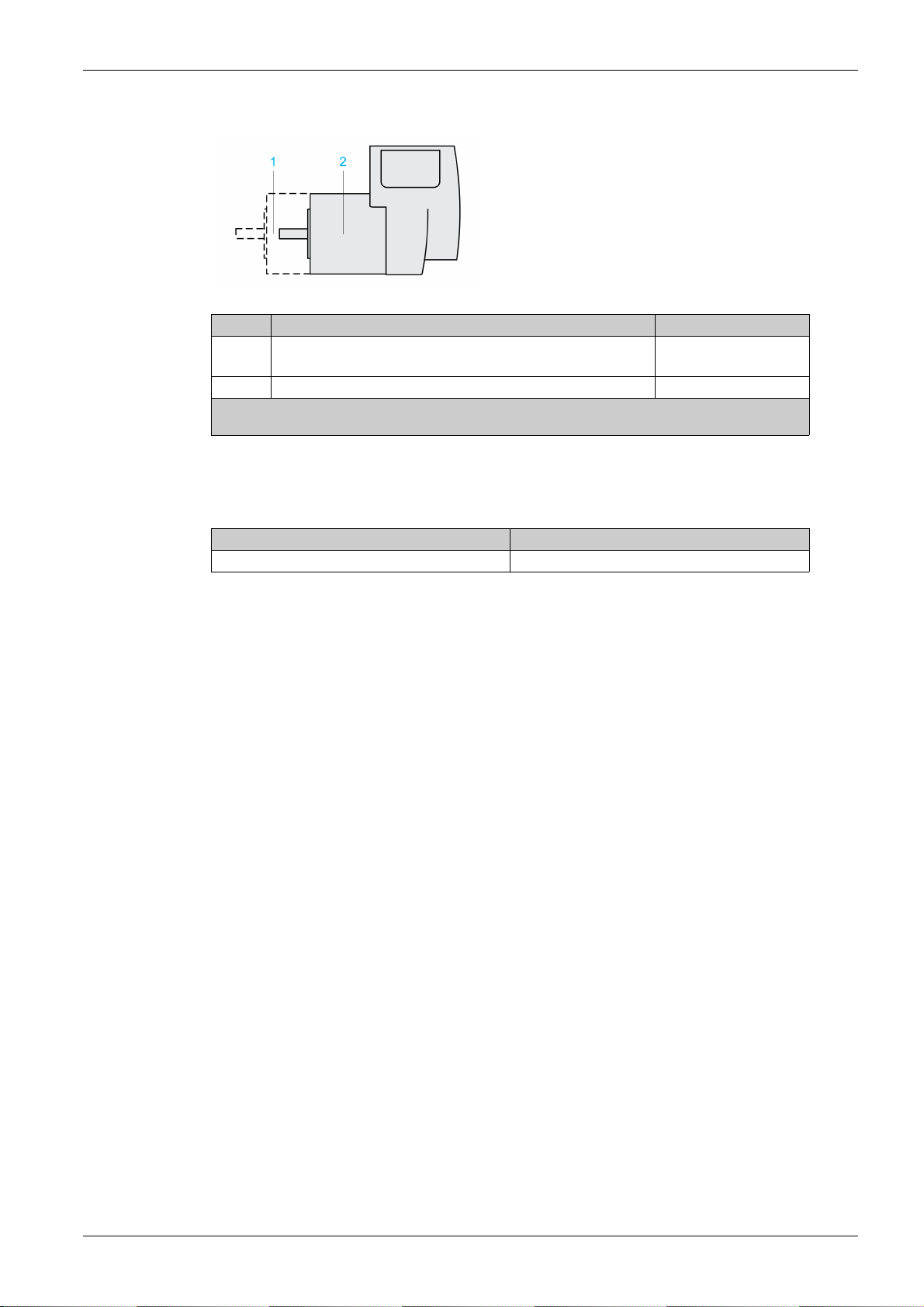
The integrated drive has the following IP degree of protection as per IEC 60529:
Item Component Degree of protection
1 Shaft bushing
2 Housing, except shaft bushing IP54
(1) In the case of mounting position IM V3 (shaft vertical, shaft end upward), the degree of protection is IP
The total degree of protection is determined by the component with the lowest degree of protection.
Pollution Degree
Technical Data
(1)
Shaft bushing with GBX gearbox (accessory)
40. The degree of protection does not relate to mounted components such as, for example, a gearbox.
IP41
IP54
Characteristic Value
Pollution degree 2
0198441113670 08/2020 21
Page 22
Technical Data
Mechanical Data
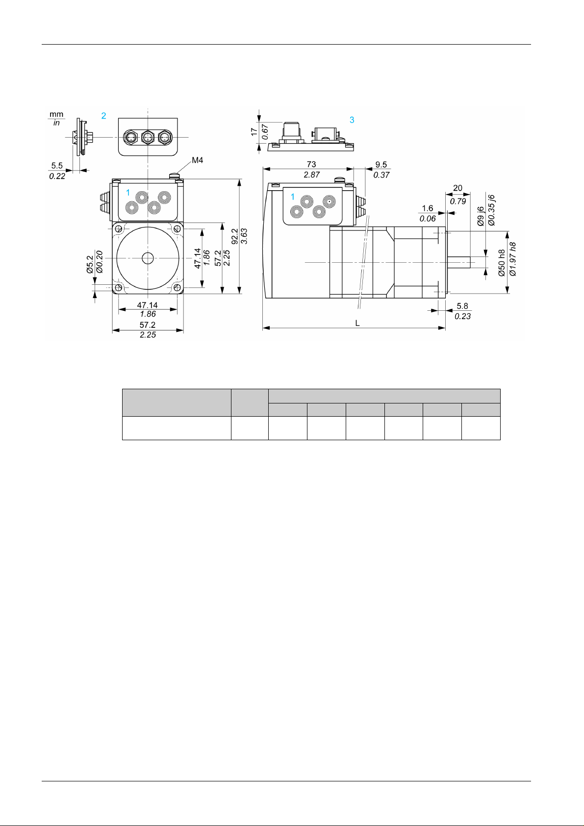
Dimensions
1 Insert with cable entry (accessory)
2 Insert kit (accessory)
3 Industrial connector (option)
Dimension Unit ILA••57...
1••1A0 1••2A0 1••1F0 2••1A0 2••2A0 2••2F0
Total length L mm
(in)
145.3
(5.72)
179.3
(7.06)
190.8
(7.51)
163.8
(6.45)
197.8
(7.79)
209.3
(8.24)
22
0198441113670 08/2020
Page 23
Electrical Data
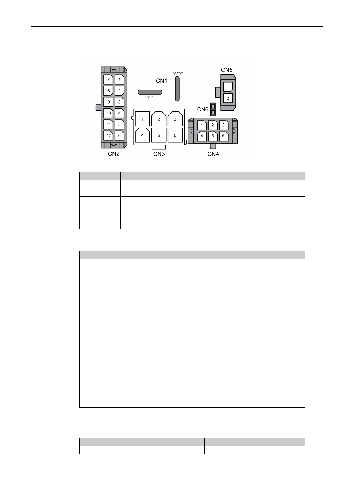
Overview of Connectors
Connection Assignment
CN1 Connectors for Vdc supply voltage
CN2 Fieldbus interface for EtherNet/IP
CN3 Commissioning interface
CN4 24 V signal interface
CN5 Connector for the safety-related function STO
CN6 Jumper for activating and deactivating the safety-related function STO
Technical Data
CN1: Vdc Supply Voltage
Characteristic Unit ILA••571 ILA••572
Nominal voltage
Minimum voltage
Maximum voltage
Ripple at nominal voltage Vpp ≤3.6 ≤3.6
Maximum input current
Winding type P
Winding type T
Peak input current
Winding type P
Winding type T
Overvoltage category - III at input of power supply unit, II at output of
Capacitance at VDC to 0VDC (for inrush current) µF 1500 1500
Fuse rating of fuse to be connected upstream A ≤15 ≤15
Type of fuse or circuit breaker to be connected
upstream
PELV - Required
Galvanic isolation - No
Vdc 24 / 48
18
55.2
A
5
7.5
A
7
11
power supply unit (as per IEC 61800-5-1)
-
Circuit-breaker (type Multi 9 - C60BP,
M9F42115 by Schneider Electric, 15 A,
tripping characteristic C), or
Blade fuse (FKS, 15 A maximum), or
Fuse (5 x 20 mm, 10 A, slow-blow)
24 / 48
18
55.2
7
7.5
8.5
9
CN2: Fieldbus Interface
The EtherNet/IP signals comply with the IEEE 802.3 standard.
Characteristic Unit Value
Transmission rate MBit 10 / 100
0198441113670 08/2020 23
Page 24

Technical Data
Characteristic Unit Value
Transmission protocol - EtherNet/IP
Galvanic isolation - Yes
CN3: Commissioning Interface
The RS485 signals comply with the RS485 standard.
Characteristic Unit Value
Transmission rate kBaud 9.6 / 19.2 / 38.4
Transmission protocol - Modbus RTU
Galvanic isolation - No
CN4: 24 V Signals
The signal inputs are not protected against reverse polarity.
Characteristic Unit Value
Logic 0 (U
Logic 1 (U
Input current at 24 Vdc mA 2
Debounce time LIO1 ... LIO4 ms 1.25 ... 1.5
Debounce time LIO1 and LIO2
Jitter LIO1 and LIO2 ms <2
Galvanic isolation - No
(1) When the function "Fast Position Capture" is used
) V -3 ... 4.5
low
)V15...30
high
(1)
ms 0.01
The internal 24 V power supply and the signal outputs are short-circuit protected.
Characteristic Unit Value
Nominal voltage V 24
Voltage range V 23 ... 25
Maximum current +24VDC_OUT mA 200
Maximum current per output mA 100
Maximum total current mA 200
Suitable for inductive loads mH 1000
Voltage drop at 50 mA load V ≤1
Galvanic isolation - No
CN5 and CN6: Safety-Related Function STO
Jumper CN6 to deactivate the safety-related function STO.
Characteristic Unit Value
Voltage for logic level 0 V -3 ...4.5
Voltage for logic level 1 V 15 ... 30
Input current STO_A
Input current STO_B
Debounce time ms 1
Detection of difference between level of STO_A
and level of STO_B
Response time of safety-related function STO ms <50
Permissible duration of test pulses from
upstream devices
PELV - Required
at 24 Vdc mA ≤10
at 24 Vdc mA ≤3
s>1
ms <1
24
0198441113670 08/2020
Page 25

Characteristic Unit Value
Galvanic isolation - No
Technical Data
0198441113670 08/2020 25
Page 26
Technical Data
Electromagnetic Compatibility
Electromagnetic Compatibility (EMC)
Characteristic Value
Emission Category C2 as per IEC 61800-3
Immunity Use permissible in second environment as per EN 61800-
NOTE: The emission category is independent of immunity. For example, if a power drive system has
emission category 2, this does not imply that it is only suitable for the first environment.
The equipment described in the present document is not intended for use in domestic, residential
environments and may not provide adequate protection to radio reception in such environments.
INSUFFICIENT ELECTROMAGNETIC COMPATIBILITY
Verify compliance with all EMC regulations and requirements applicable in the country in which the
device is to be operated and with all EMC regulations and requirements applicable at the installation
site.
Do not install and operate the devices described in the present document in residential environments.
Implement all required radio interference suppression measures and verify their effectiveness.
Failure to follow these instructions can result in death, serious injury, or equipment damage.
Compliant with IEC 61000-6-4
3
WARNING
NOTE: Compliance of the product described in the present manual with Directive 2014/30/EU of the
European Parliament and the Council (EMC Directive) is declared with reference to the harmonized
standard EN 61800-3 “Adjustable speed power drive systems - Part 3: EMC requirements and specific test
methods”. With regard to equipment of category 2, this harmonized standard and the Directive itself oblige
manufacturers to include the following statement in their product documentation: “In a domestic
environment this product may cause radio interference in which case supplementary mitigation measures
may be required.”
26
0198441113670 08/2020
Page 27
Shaft-Specific Data
Overview
If the maximum permissible forces at the motor shaft are exceeded, this will result in premature wear of the
bearing or shaft breakage.
UNINTENDED EQUIPMENT OPERATION DUE TO MECHANICAL DAMAGE TO THE MOTOR
Do not exceed the maximum permissible axial and radial forces at the motor shaft.
Protect the motor shaft from impact.
Do press output components onto the shaft unless the shaft has a thread that can be used for pressing
on.
Failure to follow these instructions can result in death, serious injury, or equipment damage.
Mounting Output Components
If the shaft has a thread, use it to press on the component to be mounted. This way there is no axial force
acting on the rolling bearing.
It is also possible to shrink-fit, clamp, or glue the component to be mounted.
Shaft Load
The following conditions apply:
The permissible force applied during pressing on must not be exceeded.
The maximum permissible radial force and the maximum permissible axial force must not be applied
simultaneously.
Nominal bearing service life in operating hours at a probability of failure of 10% (L
Mean speed of rotation n = 4000 RPM
Ambient temperature = 40 °C (104 °F)
Nominal torque = Duty type S1, 100% duty cycle
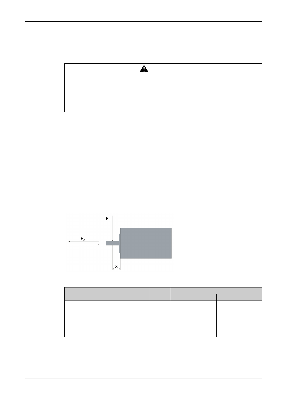
The following figure shows the points of application of forces:
WARNING
Technical Data
= 20000 hours)
10h
The following table shows the maximum radial and axial forces:
Characteristic Unit Value
ILA2•571 ILA2•572
Maximum radial force F
X = 10 mm (0.39 in)
Maximum axial force F
tension
Maximum axial force F
compression
0198441113670 08/2020 27
at 100% duty cycle and
R
at 100% duty cycle,
A
at 100% duty cycle,
A
N (lbf) 89 (20.01) 107 (24.05)
N (lbf) 104 (23.38) 104 (23.38)
N (lbf) 104 (23.38) 104 (23.38)
Page 28

Technical Data
Data for Safety-Related Function STO
Data for Safety-Related Calculations and Maintenance Plan
The safety-related function must be triggered at regular intervals. The interval depends on, among other
things, the risk assessment for the overall system. The minimum interval is one year (high demand mode
as per IEC 61508).
Use the following data of the safety-related function STO for the maintenance plan of your machine and
for the calculations for functional safety:
Lifetime of the safety-related function STO
(IEC 61508)
SFF (IEC 61508)
Safe Failure Fraction
HFT (IEC 61508)
Hardware Fault Tolerance
Type A subsystem
Safety Integrity Level (IEC 61508)
Safety Integrity Level Claim Limit (IEC 62061)
PFH (IEC 61508)
Probability of Dangerous Hardware Failure per
Hour
PL (ISO 13849-1)
Performance Level
MTTF
Mean Time to Dangerous Failure
DC (ISO 13849-1)
Diagnostic Coverage
Demand Mode (IEC 61508) - High Demand Mode (safety-related function
(1) Refer to the chapter Lifetime Safety-Related Function STO
(1)
(ISO 13849-1)
d
Years 20
%47
-1
-SIL2
1/h
- d (category 3)
Years 1995
%90
SILCL2
5.223*10
must be triggered at least once per year)
-9
(see page 244)
.
Contact your local Schneider Electric representative for additional data, if required.
28
0198441113670 08/2020
Page 29

Conditions for UL 508C and CSA
Description
If the product is used to comply with UL 508C, the following conditions must also be met:
PELV Power Supply
Use only power supply units that are approved for overvoltage category III.
Motor Overload Protection
This equipment provides Solid State Motor Overload Protection at 200 % of maximum FLA (Full Load
Ampacity).
Fuses
The product was tested with a UL-listed 15 A circuit breaker. The product must be fused either with a ULlisted circuit breaker or a fuse for "Branch Circuit Protection" as per UL 248 with a maximum current of 15 A
and DC rating.
Wiring
Use at least 60/75 °C copper conductors.
Technical Data
0198441113670 08/2020 29
Page 30

Technical Data
30
0198441113670 08/2020
Page 31

ILA2K EtherNet/IP
Engineering
0198441113670 08/2020
Engineering
Chapter 3
Engineering
What Is in This Chapter?
This chapter contains the following sections:
Section Topic Page
3.1 Electromagnetic Compatibility (EMC) 32
3.2 Power Supply 34
3.3 Functional Safety 37
3.4 EtherNet/IP Fieldbus 44
3.5 EtherNet/IP Communication 48
0198441113670 08/2020 31
Page 32

Engineering
Electromagnetic Compatibility (EMC)
Section 3.1
Electromagnetic Compatibility (EMC)
Electromagnetic Compatibility (EMC)
EMC-Compliant Wiring
This product meets the EMC requirements according to the standard EN 61800-3 if the measures
described in this manual are implemented during installation.
Signal interference can cause unexpected responses of the drive system and of other equipment in the
vicinity of the drive system.
SIGNAL AND EQUIPMENT INTERFERENCE
Install the wiring in accordance with the EMC requirements described in the present document.
Verify compliance with the EMC requirements described in the present document.
Verify compliance with all EMC regulations and requirements applicable in the country in which the
product is to be operated and with all EMC regulations and requirements applicable at the installation
site.
Failure to follow these instructions can result in death, serious injury, or equipment damage.
WARNING
Shielded Cables
WARNING
ELECTROMAGNETIC DISTURBANCES OF SIGNALS AND DEVICES
Use proper EMI shielding techniques to help prevent unintended device operation in accordance with the
standard IEC 61800-3.
Failure to follow these instructions can result in death, serious injury, or equipment damage.
Refer to the chapter Electromagnetic Compatibility
NOTE: The emission category is independent of immunity. For example, if a power drive system has
emission category 2, this does not imply that it is only suitable for the first environment.
The equipment described in the present document is not intended for use in domestic, residential
environments and may not provide adequate protection to radio reception in such environments.
(see page 26)
for technical data on EMC.
WARNING
INSUFFICIENT ELECTROMAGNETIC COMPATIBILITY
Verify compliance with all EMC regulations and requirements applicable in the country in which the
device is to be operated and with all EMC regulations and requirements applicable at the installation
site.
Do not install and operate the devices described in the present document in residential environments.
Implement all required radio interference suppression measures and verify their effectiveness.
Failure to follow these instructions can result in death, serious injury, or equipment damage.
32
EMC measures Objective
Connect large surface areas of cable shields, use cable clamps and
ground straps.
Ground shields of digital signal wires at both ends by connecting them to
a large surface area or via conductive connector housings.
Reduces emissions.
Reduces interference affecting the
signal wires, reduces emissions
0198441113670 08/2020
Page 33

Cable Installation
EMC measures Objective
Do not route fieldbus cables and signal wires in a single cable duct
Reduces mutual interference
together with lines with DC and AC voltages of more than 60 V. (Fieldbus
cables, signal lines and analog lines may be in the same cable duct)
Use separate cable ducts at least 20 cm (7.87 in) apart.
Keep cables as short as possible. Do not install unnecessary cable
loops, use short cables from the central grounding point in the control
Reduces capacitive and inductive
interference.
cabinet to the external ground connection.
Use equipotential bonding conductors in the following cases: wide-area
installations, different voltage supplies and installation across several
Reduces current in the cable
shield, reduces emissions.
buildings.
Use fine stranded equipotential bonding conductors. Diverts high-frequency
interference currents.
If motor and machine are not conductively connected, for example by an
insulated flange or a connection without surface contact, you must
Reduces emissions, increases
immunity.
ground the motor with a ground strap or a ground wire. The conductor
2
cross section must be at least 10 mm
(AWG 6).
Engineering
0198441113670 08/2020 33
Page 34

Engineering
Power Supply
Section 3.2
Power Supply
What Is in This Section?
This section contains the following topics:
External Power Supply Units 35
Wiring Information 36
Topic Page
34
0198441113670 08/2020
Page 35

External Power Supply Units
General Information
UNINTENDED EQUIPMENT OPERATION
Use power supply units that meet the PELV (Protective Extra Low Voltage) requirements.
Connect the 0 Vdc outputs of all power supply units to FE (functional earth/functional ground), for
example, for the VDC supply voltage and for the 24 Vdc voltage for the safety-related function STO.
Interconnect all 0 Vdc outputs (reference potentials) of all power supply units used for the drive.
Failure to follow these instructions can result in death, serious injury, or equipment damage.
The motor regenerates energy during deceleration and when external driving forces act on the motor shaft.
This can increase the VDC voltage up to 60 Vdc. The DC bus can absorb a limited amount of energy via
the capacitors. If the capacity of the capacitors is exceeded, this results in overvoltage on the DC bus.
Overvoltage on the DC bus causes the power stage to be disabled. The motor is no longer actively
decelerated.
LOSS OF CONTROL DUE TO REGENERATION CONDITION
Verify that the integrated drive can absorb the entire energy generated during deceleration by
performing test runs under maximum load conditions.
Install an external Braking Resistor Controller (UBC60) if the integrated drive cannot absorb the entire
energy generated under maximum load conditions.
Verify that all equipment is properly isolated from high Vdc voltage for which it is not rated, or use
properly rated equipment.
Only use power supply units that can withstand the voltage that may be present during regeneration
conditions.
Failure to follow these instructions can result in death, serious injury, or equipment damage.
Engineering
WARNING
WARNING
Fusing
Refer to the chapter Accessories
of the braking resistor controller for additional details.
Reverse polarity of the Vdc supply voltage leads to a short-circuit.
(see page 239)
for a braking resistor controller. Refer to the user guide
NOTICE
INCORRECT POLARITY
Verify correct polarity of the Vdc supply voltage before applying power.
Failure to follow these instructions can result in equipment damage.
The external power supply unit must be rated for the power requirements of the drive. Refer to the chapter
Electrical Data
Install the fusing specified in the chapter Electrical Data
(see page 23)
for the input current.
(see page 23)
.
0198441113670 08/2020 35
Page 36

Engineering
Wiring Information
Description
The reference potential of interfaces without galvanic isolation is internally connected via 0VDC. If the
negative connection (0VDC) between the power supply and the drive is interrupted, the current of the
power stage flows via the negative connection of the interfaces without galvanic isolation.
WARNING
LOSS OF CONTROL
Do not interrupt the negative connection between the power supply unit and the drive, for example, by
means of a switch or a fuse.
Connect the reference potential of interfaces with galvanic isolation to 0VDC.
Do not connect the reference potential of interfaces without galvanic isolation to 0VDC.
Failure to follow these instructions can result in death, serious injury, or equipment damage.
Wiring the product:
Keep the voltage drop on the supply cables for the Vdc supply voltage to less than 1 V. The reference
potential of some interfaces are connected to 0VDC. At higher potential differences, the communication
and control signals can be disturbed.
Decentralized power supply units for VDC close to the drives are advisable if the drives are installed at
greater distances from each other. Connect 0VDC of the individual power supply units with the largest
possible conductor cross section.
Do not connect any other power supply in parallel with the internal 24 V power supply (+24VDC_OUT).
This may cause overloads of the internal 24 V power supply.
Equipotential Bonding Conductors
Potential differences can result in excessive currents on the cable shields. Use equipotential bonding
conductors to reduce currents on the cable shields. The equipotential bonding conductor must be rated for
the maximum current.
36
0198441113670 08/2020
Page 37

Functional Safety
Section 3.3
Functional Safety
What Is in This Section?
This section contains the following topics:
Definitions 38
Function 39
Requirements for Using the Safety-Related Function STO 40
Application Examples STO 42
Engineering
Topic Page
0198441113670 08/2020 37
Page 38

Engineering
Definitions
Integrated Safety-Related Function "Safe Torque Off" STO
The integrated safety-related function STO (IEC 61800-5-2) allows for a category 0 stop as per IEC 602041 without external power contactors. It is not necessary to interrupt the supply voltage for a category 0 stop.
This reduces the system costs and the response times.
Category 0 Stop (IEC 60204-1)
In stop category 0 (Safe Torque Off, STO), the drive coasts to a stop (provided there are no external forces
operating to the contrary). The safety-related function STO is intended to help prevent an unintended startup, not stop a motor, and therefore corresponds to an unassisted stop in accordance with IEC 60204-1.
In circumstances where external influences are present, the coast down time depends on physical
properties of the components used (such as weight, torque, friction, etc.), and additional measures such
as external safety-related brakes may be necessary to help prevent any hazard from materializing. That is
to say, if this means a hazard to your personnel or equipment, you must take appropriate measures.
UNINTENDED EQUIPMENT OPERATION
Make certain that no hazards can arise for persons or material during the coast down period of the
axis/machine.
Do not enter the zone of operation during the coast down period.
Ensure that no other persons can access the zone of operation during the coast down period.
Use appropriate safety interlocks where personnel and/or equipment hazards exist.
Failure to follow these instructions can result in death, serious injury, or equipment damage.
WARNING
Category 1 Stop (IEC 60204-1)
For stops of category 1 (Safe Stop 1, SS1), you can initiate a controlled stop via the control system, or
through the use of specific functional safety-related devices. A Category 1 Stop is a controlled stop with
power available to the machine actuators to achieve the stop.
The controlled stop by the control/safety-related system is not safety-relevant, nor monitored, and does not
perform as defined in the case of a power outage or if an error is detected. This has to be implemented by
means of an external safety-related switching device with safety-related delay.
38
0198441113670 08/2020
Page 39

Function
General
Function Principle
Engineering
The safety-related function STO integrated into the product can be used to implement an "EMERGENCY
STOP" (IEC 60204-1) for category 0 stops. With an additional, approved EMERGENCY STOP safety relay
module, it is also possible to implement category 1 stops.
The safety-related function STO is triggered via two redundant signal inputs. The wiring of the two signal
inputs must be separate.
The safety-related function STO is triggered if the level at one of the two signal inputs is 0. The power stage
is disabled. The motor can no longer generate torque and coasts down without braking. An error of error
class 3 is detected.
If, within one second, the level of the other output also becomes 0, the error class remains 3. If, within one
second, the level of the other output does not become 0, the error class changes to 4.
0198441113670 08/2020 39
Page 40

Engineering
Requirements for Using the Safety-Related Function STO
General
The safety-related function STO (Safe Torque Off) does not remove power from the DC bus. The safetyrelated function STO only removes power to the motor. The DC bus voltage and the mains voltage to the
drive are still present.
ELECTRIC SHOCK
Do not use the safety-related function STO for any other purposes than its intended function.
Use an appropriate switch, that is not part of the circuit of the safety-related function STO, to
disconnect the drive from the mains power.
Failure to follow these instructions will result in death or serious injury.
After the safety-related function STO is triggered, the motor can no longer generate torque and coasts
down without braking.
WARNING
UNINTENDED EQUIPMENT OPERATION
Install a dedicated, external safety-related brake if coasting does not meet the deceleration requirements
of your application.
Failure to follow these instructions can result in death, serious injury, or equipment damage.
DANGER
Logic Type
The inputs for the safety-related function STO (inputs STO_A and STO_B) can only be wired for positive
logic.
Holding Brake and Safety-Related Function STO
When the safety-related function STO is triggered, the power stage is immediately disabled. Applying the
holding brake requires a certain amount of time. In the case of vertical axes or external forces acting on
the load, you may have to take additional measures to bring the load to a standstill and to keep it at a
standstill when the safety-related function STO is used, for example, by using a service brake.
FALLING LOAD
Ensure that all loads come to a secure standstill when the safety-related function STO is used.
Failure to follow these instructions can result in death, serious injury, or equipment damage.
If the suspension of hanging / pulling loads is a safety objective for the machine, then you can only achieve
this objective by using an appropriate external brake as a safety-related measure.
UNINTENDED AXIS MOVEMENT
Do not use the internal holding brake as a safety-related measure.
Only use certified external brakes as safety-related measures.
Failure to follow these instructions can result in death, serious injury, or equipment damage.
WARNING
WARNING
40
NOTE: The drive does not provide its own safety-related output to connect an external brake to use as a
safety-related measure.
0198441113670 08/2020
Page 41

Unintended Restart
WARNING
UNINTENDED EQUIPMENT OPERATION
Verify that your risk assessment covers all potential effects of automatic or unintended enabling of the
power stage, for example, after power outage.
Implement all measures such as control functions, guards, or other safety-related functions, required
to reliably protect against all hazards that may result from automatic or unintended enabling of the
power stage.
Verify that a master controller cannot enable the power stage in an unintended way.
Failure to follow these instructions can result in death, serious injury, or equipment damage.
WARNING
UNINTENDED EQUIPMENT OPERATION
Set the parameter IO_AutoEnable to "off" if the automatic enabling of the power stage presents
hazards in your application.
Failure to follow these instructions can result in death, serious injury, or equipment damage.
Degree of Protection when the Safety-Related Function STO is Used
You must ensure that conductive substances cannot get into the product (pollution degree 2). Moreover,
conductive substances may cause the safety-related function to become inoperative.
Engineering
INOPERABLE SAFETY-RELATED FUNCTION
Ensure that conductive substances (water, contaminated or impregnated oils, metal shavings, etc.)
cannot get into the drive.
Failure to follow these instructions can result in death, serious injury, or equipment damage.
Protected Cable Installation
If short circuits and other wiring errors such as a cross circuit between the signals of the safety-related
function STO can be expected in connection with safety-related signals, and if these short circuits and
cross circuits are not detected by upstream devices, protected cable installation as per ISO 13849-2 is
required.
In the case of an unprotected cable installation, the two signals (both channels) of a safety-related function
may be connected to external voltage if a cable is damaged. If the two channels are connected to external
voltage, the safety-related function is no longer operative.
ISO 13849-2 describes protected cable installation for cables for safety-related signals. The cables for the
safety-related function STO must be protected against external voltage. A shield with ground connection
helps to keep external voltage away from the cables for the signals of the safety-related function STO.
Ground loops can cause problems in machines. A shield connected at one end only is sufficient for
grounding and does not create a ground loop.
Use shielded cables for the signals of the safety-related function STO.
Do not use the cable for the signals of the safety-related function STO for other signals.
Connect one end of the shield.
WARNING
0198441113670 08/2020 41
Page 42

Engineering
Application Examples STO
Example of Category 0 stop
Use without EMERGENCY STOP safety relay module, category 0 stop.
Example of category 0 stop:
In this example, when an EMERGENCY STOP is activated, it leads to a category 0 stop.
The safety-related function STO is triggered via a simultaneous 0-level at both inputs (time offset of less
than 1 s). The power stage is disabled and an error of error class 3 is detected. The motor can no longer
generate torque.
If the motor is not already at a standstill when the safety-related function STO is triggered, it decelerates
under the salient physical forces (gravity, friction, etc.) active at the time until presumably coasting to a
standstill.
If coasting of the motor and its potential load is unsatisfactory as determined by your risk assessment, an
external safety-related brake may also be required.
WARNING
UNINTENDED EQUIPMENT OPERATION
Install a dedicated, external safety-related brake if coasting does not meet the deceleration requirements
of your application.
Failure to follow these instructions can result in death, serious injury, or equipment damage.
Refer to the chapter Holding Brake and Safety-Related Function STO
(see page 40)
.
42
0198441113670 08/2020
Page 43

Example of Category 1 stop
Use with EMERGENCY STOP safety relay module, category 1 stop.
Example of category 1 stop with external Preventa XPS-AV EMERGENCY STOP safety relay module:
Engineering
In this example, when an EMERGENCY STOP is activated, it leads to a category 1 stop.
The EMERGENCY STOP safety relay module requests an immediate stop (undelayed) of the drive. After
the time delay set in the EMERGENCY STOP safety relay module has elapsed, the EMERGENCY STOP
safety relay triggers the safety-related function STO.
The safety-related function STO is triggered via a simultaneous 0-level at both inputs (time offset of less
than 1 s). The power stage is disabled and an error of error class 3 is detected. The motor can no longer
generate torque.
If coasting of the motor and its potential load is unsatisfactory as determined by your risk assessment, an
external safety-related brake may also be required.
WARNING
UNINTENDED EQUIPMENT OPERATION
Install a dedicated, external safety-related brake if coasting does not meet the deceleration requirements
of your application.
Failure to follow these instructions can result in death, serious injury, or equipment damage.
Refer to the chapter Holding Brake and Safety-Related Function STO
(see page 40)
.
0198441113670 08/2020 43
Page 44

Engineering
EtherNet/IP Fieldbus
Section 3.4
EtherNet/IP Fieldbus
What Is in This Section?
This section contains the following topics:
General 45
Messaging and Message Types 47
Topic Page
44
0198441113670 08/2020
Page 45

General
ODVA
Number of Nodes
Cable Length
Drive Profiles
Engineering
The ODVA is the proprietor of the specifications for the EtherNet/IP network and EtherNet/IP data terminal
equipment. For more information on the ODVA see:
http://www.odva.org
The number of nodes in an EtherNet/IP network is theoretically unlimited; it depends on the subnet size
and on whether or not a CIP router is used. For example, 254 nodes are possible in a class C subnet.
The maximum cable length is 100 m (328 ft) between EtherNet/IP terminal points and 90 m (295 ft)
between infrastructure components. However, interference in industrial environments may require you to
use shorter cables.
The product supports the following drive profiles:
"Generic Profile" (CIP)
“Drive Profile Lexium” (manufacturer-specific)
Communication Means
The product supports the following communication means:
Overview of communication means:
Group 2 servers
UCMM-enabled devices
Class 1 connections via assemblies:
Master-slave connections:
The product identifies itself as CIP “Generic Device” (Device Type = 0 hex).
“Explicit Message”
“Polled I/O Connection”
“Fragmentation Protocol” support
Dynamic establishment of 2 “Explicit Connections” and one “I/O Connection”
Data Link Layer
The EtherNet/IP data link layer uses the transmission mechanisms as per IEEE 802.3 Standard Ethernet
specification (edition 2002).
0198441113670 08/2020 45
Page 46

Engineering
Physical Layer
Industrial EtherNet/IP specifies minimum requirements in terms of ambient conditions, cabling, and
connectors, based on IEC, ANSI, TIA, and EIA standards.
The connectors required for Industrial EtherNet/IP include M12-4 connectors, D-coded. Use CAT5e or
CAT6 cables for Industrial EtherNet/IP.
Copper media may be used only for distances up to 100 m (328 ft).
Object Class, Instance, Attribute, Service
The EtherNet/IP approach is object-oriented. CIP defines object classes; one or more instances (objects)
can be derived from such object classes. The attributes of an object class or the instance derived from it
contain the various parameters. Services are actions that are possible with these attributes.
Example
Class Instance Attribute Attribute value Service
Motor data Motor_1 MaxSpeed 4000 RPM Get
Motor data Motor_2 MaxSpeed 3000 RPM Get
CIP Object Model
The following object classes from the CIP object model are available:
The vendor-specific object class IDs 101 to 163 correspond to the object dictionary (class ID = object group
+ 100). The attributes of a class correspond to the subindex entry within the object group.
Communication Model
EtherNet/IP uses the producer-consumer communication model. The nodes monitor the bus as to whether
a data packet with the Identifier they support is available. Data packets that are sent by producers can only
be received by the consumers of these packets.
Groups of Connections
EtherNet/IP is a connection-oriented network. Connections must be established and managed between
two nodes. There are 4 connection groups with different priorities:
Object class Class ID Instance ID
Identity Object 1 (01 hex) 1
Message Router Object 2 (02 hex) 1
Assembly Object 4 (04 hex) 103 = Output Assembly, consuming
113 = Input Assembly, producing
Connection Manager Object 6 (06 hex) 1= Explicit Message
Vendor-specific objects 101 ... 163 (65 ... A3 hex) 1
Port Object 244 (F4 hex) 1
TCP/IP Object 245 (F5 hex) 1
Ethernet Link Object 246 (F6 hex) 2
Group 1 Top-priority process data (highest priority)
Group 2 For master-slave connections
Group 3 For Explicit Messages
Group 4 Reserved group (lowest priority)
EDS File (Electronic Data Sheet)
The EDS file contains device-specific and vendor-specific descriptions of the parameters for a drive. The
EDS file also contains the fieldbus-specific communication parameters.
46
0198441113670 08/2020
Page 47

Messaging and Message Types
General
EtherNet/IP is based on TCP/IP and UDP/IP technologies that are used without modification. TCP/IP is
used for the transmission of Explicit Messages while UDP/IP is used for I/O Messages.
Messaging and Message Types
EtherNet/IP defines several message types for communication. The drive uses the message types “Explicit
Message” and “I/O Message”.
Explicit Messages
Explicit Messaging connections are point-to-point connections between two network nodes that are used
for transactions of the type request - response. The data field of Explicit Messages contains both protocol
data and application-specific commands.
An Explicit Message (EtherNet/IP-specific or vendor-specific) is used to read or write an individual
parameter.
The parameter is accessed by means of Class.Instance.Attribute as per CIP.
I/O Messages
I/O Messages, also referred to as Implicit Messages, are transmitted via UDP/IP. I/O Message connections
are often established as One-to-Many relationships in the producer-consumer multicast model of
EtherNet/IP. The data fields of I/O Messages contain no protocol information, but only time-critical I/O data.
I/O Messages are considerably smaller than Explicit Messages, thus allowing for faster processing. These
messages are used to transport application-specific I/O data over the network at regular intervals. The
meaning of the data is defined at the time the connection is established. I/O Messages can contain socalled Assemblies of several parameters that can be transmitted with a single message. The parameters
for configuring EtherNet/IP communication are described in chapter Commissioning
Engineering
(see page 81)
.
Command Processing: Transmit Data and Receive Data
The master sends a command to the drive system (slave) to execute a motion command, activate functions
or request information from the slave. The slave executes the command and acknowledges it with a
response message that may contain an error message if an error has been detected.
The master can send new commands as soon as it has received acknowledgment concerning the current
command. Acknowledgment information and error messages are included in the transmitted data in bitcoded form. The master must then continuously monitor for completion of the command by evaluating the
acknowledgment from the slave. I/O messages are a special case. I/O messages are not acknowledged
by the slave.
0198441113670 08/2020 47
Page 48

Engineering
EtherNet/IP Communication
Section 3.5
EtherNet/IP Communication
What Is in This Section?
This section contains the following topics:
Communication via I/O Messages 49
Output Assembly, Instance 103 50
Input Assembly, Instance 113 51
Handshake via the Bit "MT" (Mode Toggle) 53
Topic Page
48
0198441113670 08/2020
Page 49

Communication via I/O Messages
Overview
An I/O Message is used for realtime exchange of process data. Transmission is very fast because the data
is sent without administration data and a transmission acknowledgment from the recipient is not required.
The master can control the operating states of the slave by means of I/O Message, for example, enable
and disable the power stage, trigger a Quick Stop, reset detected errors and activate operating modes.
Changing operating states and activating operating modes must be done separately. An operating mode
can only be activated in the operating state “Operation Enabled”.
Output, Input
Output and Input refer to the direction of data transmission from the perspective of the master.
Output: Commands from the master to the slave
Input: Status messages from the slave to the master
Assembly
I/O Messages contain a collection (Assembly) of different parameters that are transmitted with a single
message.
The following Assemblies are available:
Output Assembly, instance 103
Input Assembly, instance 113
Engineering
Polled I/O Connection
The Assemblies are used in a Polled I/O Connection. A Polled I/O Connection is initiated by the master
with a Poll Command. The Slave responds with a Poll Response.
0198441113670 08/2020 49
Page 50

Engineering
Output Assembly, Instance 103
Overview
Memory map for Output Assembly data.
Byte Name Parameter address CIP
0 Attribute (Subindex) Parameter channel
1 Command (AK)
2 ... 3 Class (Index)
4 ... 7 Data
8 ... 11 Ref_32 -
12 ... 13 Ref_16 -
14 modeControl -
15 driveControl -
16 ... 19 RAMPacc CIP 106.1.10
20 ... 23 RAMPdecel CIP 106.1.11
24 ... 39 Reserved -
Bytes “Attribute” and “Command”, Word “Class” and Double Word “Data”
The bytes “Attribute” and “Command”, the word “Class” and the double word “Data” are used to read and
write parameters (parameter channel).
Double Word “Ref_32” and Word “Ref_16”
The two double words “Ref_32” and the word “Ref_16” are used to set two operating mode-specific values.
The meaning is described in the chapters covering the individual operating modes.
Byte “modeControl”
The word “modeControl” is used to set the operating mode.
Refer to the chapter Starting and Changing an Operating Mode
of the bits.
Byte “driveControl”
The word “driveControl” is used to set the operating state.
Refer to the chapter Changing the Operating State via Fieldbus
of the bits.
Double Words “RAMPacc” and “RAMPdecel”
The two double words “RAMPacc” and “RAMPdecel” are used to set the acceleration and the deceleration.
They correspond to the parameters of the same name.
(see page 134)
(see page 131)
for a detailed description
for a detailed description
50
0198441113670 08/2020
Page 51

Input Assembly, Instance 113
Overview
Memory map for Input Assembly data.
Byte Name Parameter address CIP
0 Attribute (Subindex) Parameter channel
1 Command (AK)
2 ... 3 Class (Index)
4 ... 7 Data
8 ... 9 Special Functions -
10 ... 11 ActionWord -
12 Digital IO -
13 modeStat -
14 ... 15 driveStat -
16 ... 19 _p_actusr CIP 130.1.13
20 ... 23 _n_act CIP 130.1.8
24 ... 39 Reserved -
Bytes “Attribute” and “Command”, Word “Class” and Double Word “Data”
The bytes “Attribute” and “Command”, the word “Class” and the double word “Data” are used to read and
write parameters (parameter channel).
Engineering
Word “Special Functions”
The word “Special Functions” is used to indicate the state of the counter of the capture inputs.
Bit Meaning
0 Bit 0 of the counter of the capture input 1.
1 Bit 1 of the counter of the capture input 1.
2 Bit 0 of the counter of the capture input 2.
3 Bit 1 of the counter of the capture input 2.
4 ... 15 Reserved
Word “ActionWord”
The word “ActionWord” is used to provide information on the motor and profile generator.
Bit Meaning
0 ... 5 Reserved
6 MOTZ: Motor at a standstill
7 MOTP: Motor movement in positive direction
8 MOTN: Motor movement in negative direction
9 PWIN: Inside position deviation window
10 Reserved
11 TAR0: Profile generator at standstill
12 DEC: Profile generator decelerates
13 ACC: Profile generator accelerates
14 CNST: Profile generator moves at constant velocity
15 Reserved
Byte “Digital IO”
The byte “Digital IO” is used to indicate the state of the digital signal inputs.
0198441113670 08/2020 51
Page 52

Engineering
Bit Signal Factory setting
0
1
2
3
4
5
6 ... 7
Byte “modeStat”
The byte “modeStat” is used to indicate the current operating mode.
Refer to the chapter Indicating the Operating Mode
Word “driveStat”
The current operating state is indicated with the “driveStat” word.
Refer to the chapter Indication of the Operating State via Fieldbus
of the bits.
Double Word “_p_actusr”
The double word “_p_actusr” indicates the actual position. The value corresponds to the parameter
_p_actusr.
LIO1
LIO2
LIO3
LIO4
STO_A
STO_B
-
Signal input function Input Positive Limit Switch (LIMP)
Signal input function Input Negative Limit Switch (LIMN)
Signal input function Input Free Available
Signal input function Input Reference Switch (REF)
Signal STO_A of safety-related function STO
Signal STO_B of safety-related function STO
Reserved
(see page 133)
for a detailed description of the bits.
(see page 129)
fo r a de t ailed d escri pti on
Double Word “_n_act”
The double word “_n_act” indicates the actual velocity. The value corresponds to the parameter _n_act.
52
0198441113670 08/2020
Page 53

Handshake via the Bit "MT" (Mode Toggle)
Mode Toggle
Synchronized processing can be carried out with the transmit data in the word "dmControl" bit "MT" (Mode
Toggle) and the receive data in the word "mfStat", bit "ME" (Mode Error) and bit "MT" (Mode Toggle).
Synchronized processing means that the master waits for feedback messages from the slave so it can
respond appropriately.
The bit "MT" (Mode Toggle) is effective with a rising edge and a falling edge.
Example 1: Positioning
The master starts a movement. At points in time t
It waits for the end of the movement. The end is identified by bit "x_end" = 1.
Mode Toggle Handshake:
Engineering
, t2 ..., the master verifies the responses from the slave.
1
1 Master starts movement with “Mode Toggle” = 1
2 Slave signals that movement is running with “Mode Toggle” = 1; at the same time “x_end” = 0
3 Slave signals “movement terminated” with “x_end” = 1
Example 2: Short-Distance Movement
The master starts a movement whose duration is shorter than the request cycle of the master. At point in
, the movement is already terminated. Bit “x_end” does not allow the master to detect whether the
time t
1
movement has already been terminated or has not yet started. However, it can identify this with the bit “MT“
(Mode Toggle).
Mode Toggle Handshake, short-distance movement:
1 Master starts movement with “Mode Toggle” = 1
2 Slave signals that movement is running with “Mode Toggle” = 1; at the same time “x_end” = 0
3 Slave signals “movement terminated” with “x_end” = 1
0198441113670 08/2020 53
Page 54

Engineering
54
0198441113670 08/2020
Page 55

ILA2K EtherNet/IP
Installation
0198441113670 08/2020
Installat ion
Chapter 4
Installation
What Is in This Chapter?
This chapter contains the following sections:
Section Topic Page
4.1 Mechanical Installation 56
4.2 Electrical Installation 60
4.3 Verifying Installation 80
0198441113670 08/2020 55
Page 56

Installation
Mechanical Installation
Section 4.1
Mechanical Installation
What Is in This Section?
This section contains the following topics:
Before Mounting 57
Mounting the Integrated Drive 58
Topic Page
56
0198441113670 08/2020
Page 57

Before Mounting
General
Installation
An engineering phase is mandatory prior to mechanical and electrical installation. See chapter Engineering
(see page 31)
for basic information.
DANGER
ELECTRIC SHOCK OR UNINTENDED EQUIPMENT OPERATION
Keep foreign objects from getting into the product.
Verify the correct seating of seals and cable entries in order to avoid contamination such as deposits
and humidity.
Failure to follow these instructions will result in death or serious injury.
Conductive foreign objects, dust or liquids may cause safety-related functions to become inoperative.
WARNING
LOSS OF SAFETY-RELATED FUNCTION CAUSED BY FOREIGN OBJECTS
Protect the system against contamination by conductive substances.
Failure to follow these instructions can result in death, serious injury, or equipment damage.
Inspecting the Product
The metal surfaces of the product may exceed 70 °C (158 °F) during operation.
CAUTION
HOT SURFACES
Avoid unprotected contact with hot surfaces.
Do not allow flammable or heat-sensitive parts in the immediate vicinity of hot surfaces.
Verify that the heat dissipation is sufficient by performing a test run under maximum load conditions.
Failure to follow these instructions can result in injury or equipment damage.
Verify the product version by means of the Type Code
Prior to mounting, inspect the product for visible damage.
Damaged products may cause electric shock or unintended equipment operation.
(see page 18)
on the Nameplate
(see page 17)
DANGER
ELECTRIC SHOCK OR UNINTENDED EQUIPMENT OPERATION
Do not use damaged products.
Keep foreign objects (such as chips, screws or wire clippings) from getting into the product.
Failure to follow these instructions will result in death or serious injury.
Contact your local Schneider Electric representative if you detect any damage whatsoever to the products.
.
Mounting Surface for Flange
The integrated drive features four holes for mounting it to a flange.
The mounting surface must be plane, stable, clean, deburred, low-vibration, and grounded. Functional
grounding must be established either via the mounting flange or via the functional ground connection.
Verify that the mounting surface meets all requirements in terms of dimensions and tolerances. See
chapter Mechanical Data
Painted surfaces have an insulating effect. Verify that the motor flange is mounted in such a way as to allow
for good electrical and thermal conductivity.
0198441113670 08/2020 57
(see page 22)
.
Page 58

Installation
Mounting the Integrated Drive
General
Motors can generate strong local electrical and magnetic fields. This can cause interference in sensitive
devices.
ELECTROMAGNETIC FIELDS
Keep persons with electronic medical implants, such as pacemakers, away from the motor.
Do not place electromagnetically sensitive devices in the vicinity of the motor.
Failure to follow these instructions can result in death, serious injury, or equipment damage.
Electrostatic discharge to the shaft may cause incorrect operation of the encoder system and result in
unanticipated motor movements and damage to the bearing.
UNINTENDED MOVEMENT CAUSED BY ELECTROSTATIC DISCHARGE
Use conductive components such as antistatic belts or other suitable measures to avoid static charge by
motion.
Failure to follow these instructions can result in death, serious injury, or equipment damage.
WARNING
WARNING
If the permissible environmental conditions are not respected, external substances from the environment
may penetrate the product and cause unintended movement or equipment damage.
WARNING
UNINTENDED EQUIPMENT OPERATION
Verify that the environmental conditions are respected.
Keep liquids from getting to the shaft bushing.
Do not clean the product with a pressure washer.
Failure to follow these instructions can result in death, serious injury, or equipment damage.
Motors are very heavy relative to their size. The great mass of the motor can cause injuries and damage.
WARNING
HEAVY AND/OR FALLING PARTS
Use a suitable crane or other suitable lifting gear for mounting the motor if required by the weight of
the motor.
Use the necessary personal protective equipment (for example, protective shoes, protective glasses
and protective gloves).
Mount the motor so that it cannot come loose (use of securing screws with appropriate tightening
torque), especially in cases of fast acceleration or continuous vibration.
Failure to follow these instructions can result in death, serious injury, or equipment damage.
58
CAUTION
IMPROPER APPLICATION OF FORCES
Do not use the motor as a step to climb into or onto the machine.
Do not use the motor as a load-bearing part.
Use hazard labels and guards on your machine to help prevent the improper application of forces on
the motor.
Failure to follow these instructions can result in injury or equipment damage.
0198441113670 08/2020
Page 59

Clearances and Ventilation
When selecting the position of the device, take into account the following:
No minimum clearances are required for installation. However, free convection must be possible.
Avoid heat accumulations.
Do not mount the device close to heat sources.
Do not mount the device on flammable materials.
The heated airflow from other devices and components must not heat up the air used for cooling the
device.
If the thermal limits are exceeded during operation, the power stage of the drive is disabled
(overtemperature).
Mounting Positions
The following mounting positions defined by IEC 60034-7 are permissible:
Installation
IM B5: Motor shaft horizontal
IM V1: Motor shaft vertical, shaft end to the bottom
IM V3: Motor shaft vertical, shaft end to the top
Mounting
When the integrated drive is mounted to the mounting surface, it must be accurately aligned axially and
radially and make even contact with the mounting surface. No uneven mechanical forces must be applied
when the mounting screws are tightened.
See chapter Technical Data
Mounting Output Components
If the maximum permissible forces at the motor shaft are exceeded, this will result in premature wear of the
bearing or shaft breakage.
UNINTENDED EQUIPMENT OPERATION DUE TO MECHANICAL DAMAGE TO THE MOTOR
Do not exceed the maximum permissible axial and radial forces at the motor shaft.
Protect the motor shaft from impact.
Do not exceed the maximum permissible axial force when pressing components onto the motor shaft.
Failure to follow these instructions can result in death, serious injury, or equipment damage.
Output components such as pulleys and couplings must be mounted with suitable equipment and tools.
Motor and output component must be accurately aligned both axially and radially. If the motor and the
output component are not accurately aligned, this causes runout and premature wear.
The maximum axial and radial forces acting on the shaft must not exceed the maximum shaft load values
specified
(see page 27)
(see page 19)
.
for data, dimensions and degrees of protection (IP).
WARNING
0198441113670 08/2020 59
Page 60

Installation
Electric al Ins tallat ion
Section 4.2
Electrical Installation
What Is in This Section?
This section contains the following topics:
Overview of Procedure 61
Connection Overview 63
Connection Via Cable Entry 64
Connection Via Industrial Connectors 67
Connection of CN1 - Vdc Supply Voltage 68
Connection of CN2 - Fieldbus 70
Connection of CN3 - RS485 72
Connection of CN4 - 24 V Signal Interface 74
Connection of CN5 - Safety-Related Function STO 76
Connection of Accessories for 24 V Signals and Safety-Related Function STO 78
Topic Page
60
0198441113670 08/2020
Page 61

Overview of Procedure
General Information
ELECTRIC SHOCK OR UNINTENDED EQUIPMENT OPERATION
Keep foreign objects (such as chips, screws or wire clippings) from getting into the product.
Failure to follow these instructions will result in death or serious injury.
ELECTRIC SHOCK CAUSED BY INSUFFICIENT GROUNDING
Verify compliance with all local and national electrical code requirements as well as all other applicable
regulations with respect to grounding of the entire drive system.
Ground the drive system before applying voltage.
Do not use conduits as functional ground conductors; use a functional ground conductor inside the
conduit.
The cross section of the functional ground conductor must comply with the applicable standards.
Do not consider cable shields to be functional ground conductors.
Failure to follow these instructions will result in death or serious injury.
Installation
DANGER
DANGER
DANGER
ELECTRIC SHOCK CAUSED BY INCORRECT POWER SUPPLY UNIT
Use power supply units that meet the PELV (Protective Extra Low Voltage) requirements.
Connect the negative outputs of all power supply units to PE (protective earth/protective ground), for
example, for the VDC supply voltage and for the 24 Vdc voltage for the safety-related function STO.
Interconnect all negative outputs (reference potentials) of all power supply units used for the integrated
drive.
Failure to follow these instructions will result in death or serious injury.
WARNING
UNINTENDED EQUIPMENT OPERATION
Do not connect any wiring to reserved, unused connections, or to connections designated as No
Connection (N.C.).
Failure to follow these instructions can result in death, serious injury, or equipment damage.
The VDC connection of the product does not have an inrush current limitation. If the voltage is applied by
means of switching of contacts, damage to the contacts or contact welding may result.
NOTICE
PERMANENT DAMAGE TO CONTACTS
Switch the power input (primary side) of the power supply unit.
Do not switch the output voltage (secondary side) of the power supply unit.
Failure to follow these instructions can result in equipment damage.
The installation procedure must be performed without voltage present.
0198441113670 08/2020 61
Page 62

Installation
Overview of the Procedure for Electrical Installation
Depending on the space conditions in your machine and other factors, you can first perform the mechanical
installation
(see page 56)
of the integrated drive and then the electrical installation. However, it is also
possible to first perform the electrical installation, then commission the integrated drive and finally mount
the integrated drive in the machine.
62
0198441113670 08/2020
Page 63

Connection Overview
Overview of Printed Circuit Board Connectors
Connection Assignment
CN1 Connector for Vdc supply voltage
CN2 Connector for fieldbus Ethernet/IP
CN3 Connector for commissioning interface (RS-485)
CN4 Connector for 24 Vdc signals
CN5 Connector for the safety-related function STO
CN6 Jumper for activating and deactivating the safety-related function STO
Installation
The integrated drive can be connected via cable entries or industrial connectors.
Refer to the chapter Connection Via Cable Entry
Connectors
(see page 67)
for details.
(see page 64)
or to the chapter Connection Via Industrial
0198441113670 08/2020 63
Page 64

Installation
Connection Via Cable Entry
Mounting Cables to Cable Entries
Mounting cables to the cable entry:
1 Unshielded cables
2 Shielded cables
Mounting Connectors
Step Action
1 Trim the cable bushings so that the diameter of the opening matches the diameter of the cable.
The specified degree of protection IP54 can only be achieved with properly trimmed cable
bushings.
2 (A) Strip the jacket of the cables by a length of 70 mm (2.76 in).
3 (B) Shorten the shield to a length of 10 mm (0.4 in).
4 (C) Slide the shielding braid back over the cable jacket.
5 (D) Loosen the strain relief.
6 Push the cables though the strain relief.
7 Glue EMC shielding film around the shield.
8 Pull the cable back to the strain relief.
9 Fasten the strain relief.
The following table lists the parts and data required for mounting connectors. Connector housings and
crimp contacts are included in the accessories kits. Refer to the chapter Accessories and Spare Parts
(see page 239)
Connection Conductor cross section
CN1 0.75 ... 1.5 (AWG
CN2 0.2 ... 0.6 (AWG 24 ... 20) 2.5 ... 3.0 43030-0007 63819-0000 Molex Micro-Fit
CN3 0.2 ... 1.0 (AWG 24 ... 18) 3.0 ... 3.5 39-00-0060 63819-0901 Molex Mini-Fit Jr.
CN4 0.2 ... 0.6 (AWG 24 ... 20) 2.5 ... 3.0 43030-0007 63819-0000 Molex Micro-Fit
CN5 0.34 ... 0.6 (AWG 20) 2.5 ... 3.0 43030-0007 63819-0000 Molex Micro-Fit
.
[mm²]
18 ... 16)
2.5 ... 4.0 (AWG 12)
Stripping
length [mm]
5 ... 6 160773-6
Manufacturer's
crimp contact
no.
341001-6
Crimping
tool
654174-1 Tyco
Connector
manufacturer
Electronics
Connector
type
Positive
Lock
1-926522-1
3.0
43025-1200
39-01-2065
3.0
43025-0600
3.0
43645-0200
64
0198441113670 08/2020
Page 65

Assembling the Cables
Procedure:
Installation
Step Action
1 Strip the ends of the wires.
2 Attach cable lugs and crimp contacts. Verify that you use the correct crimp contacts and the
matching crimping tool.
3 Slide the cable lugs and crimp contacts straight into the connector until they snap in place.
1 CN1 Supply voltage Vdc
2 CN2 Fieldbus
3 CN3 Commissioning
4 CN4 24 V signal interface
5 Shield wire with EMC shield film
Mounting the Cable Entry
Step Action
1 Unscrew the cover of the connector housing.
2 Remove the shipping locks made of cardboard.
0198441113670 08/2020 65
Page 66

Installation
Step Action
3 Set the parameter switches as they are difficult to access once the cables have been connected.
For a description of the parameter switches, see chapter Fieldbus Integration
(see page 86)
4 Connect the connectors of the assembled cables to the matching sockets. The connectors must
snap in. Only pull the connector housing (not the cable).
5 Plug the cable entry into one of the two cutouts provided. The side to be used for the cable entry
depends on the space available in your system.
The pointed corners of the cable entry must point in the direction of the cover of the connector
housing. Degree of protection IP54 is not reached if the cable entry is mounted the other way
around.
6 Close the cutout that is not used with a sealing insert for cutouts.
7 Finally, screw the cover of connector housing cover back into place with a tightening torque of
1.1 Nm (9.74 lbin).
If screws are lost, use M3 x 12 as a replacement.
.
66
0198441113670 08/2020
Page 67

Connection Via Industrial Connectors
Overview
Interface Connector used
Supply voltage VDC Hirschmann STASEI 200
Connector for fieldbus Ethernet/IP Circular connector M12, 4 poles, D-coded
24 V signal inputs and outputs Circular connector M8, 3-pin
Safety-related function STO Circular connector M8, 4-pin
Installation
Refer to the chapter Accessories and Spare Parts
and connector kits.
(see page 239)
for information on pre-assembled cables
0198441113670 08/2020 67
Page 68

Installation
Connection of CN1 - Vdc Supply Voltage
Description
The Vdc supply voltage is connected by means of printed circuit board connectors or industrial connectors.
Use pre-assembled cables to reduce the risk of wiring errors.
Verify that wiring, cables, and connected interfaces meet the PELV circuit requirements.
Cable Specifications CN1 (Vdc Supply Voltage)
Characteristic Unit Value
Shield - Not required
Twisted pair - Not required
PELV - Required
Minimum conductor cross section
Maximum connection cross section
Connector Specifications CN1 (Vdc Supply Voltage)
Two different crimp terminals are available for different conductor cross sections. It is possible to connect
two wires via a single crimp terminal to daisy-chain multiple drives.
2
mm
(AWG)
2
mm
(AWG)
0.75 (18)
4.0 (12)
Characteristic Value/Description
Connector housing Tyco Electronics, Positive Lock 1-926522-1
Crimp terminal for conductor cross section 0.75 ... 1.5
(AWG 18 ... 16)
Crimp terminal for conductor cross section 2.5 ... 4.0
(AWG 12)
Stripping length 5 ... 6 mm (0.20 ... 0.24 in)
Crimping tool Tyco Electronics, 654174-1
Tyco Electronics, Positive Lock 160773-6
Tyco Electronics, Positive Lock 341001-6
Pin Assignments Printed Circuit Board Connector CN1 (Vdc Supply Voltage)
68
Designation Description
VDC
OVDC
(1) Number relates to pre-assembled cables
Supply Voltage 1
Reference potential VDC 2
(1)
Number
0198441113670 08/2020
Page 69

Pin Assignments Industrial Connector CN1 (Vdc Supply Voltage)
Installation
Pin Signal Description
1
2
VDC
OVDC
Supply Voltage 1
Reference potential Vdc 2
(1) Number relates to pre-assembled cables
Number
(1)
0198441113670 08/2020 69
Page 70

Installation
Connection of CN2 - Fieldbus
Description
The fieldbus interface allows you to network the drive as a slave in an Ethernet/IP network.
The fieldbus is connected by means of printed circuit board connectors or industrial connectors.
Use pre-assembled cables to reduce the risk of wiring errors.
Verify that wiring, cables, and connected interfaces meet the PELV requirements.
Cable Specifications CN2 (Fieldbus)
Characteristic Unit Value
Shield - Required
Shield grounded at both ends - Required
Twisted pair - Required
PELV - Required
Maximum cable length m (ft) 100 (328)
Minimum conductor cross section
Maximum connection cross section
mm
mm
2
(AWG)
2
(AWG)
0.25 (22)
0.6 (20)
Connector Specifications CN2 (Fieldbus)
Characteristic Value/Description
Connector housing Molex, Micro-Fit 3.0, 43025-1200
Crimp terminal Molex, Micro-Fit 3.0, 43030-0007
Stripping length 2.5 ... 3.0 mm (0.10 ... 0.12 in)
Crimping tool Molex, 63819-0000
Extraction tool Molex, 11-03-0043
Pin Assignments Printed Circuit Board Connector CN2 (Fieldbus)
70
Pin assignment port 0:
Pin Signal Description (drive end)
9
10
11
12
Tx+
Tx-
Rx+
Rx-
Fieldbus Tx+
Fieldbus Tx-
Fieldbus Rx+
Fieldbus Rx-
Pin assignment port 1:
0198441113670 08/2020
Page 71

Pin Signal Description (drive end)
3
4
5
6
Tx+
Tx-
Rx+
Rx-
Fieldbus Tx+
Fieldbus Tx-
Fieldbus Rx+
Fieldbus Rx-
Pin Assignments Industrial Connector CN2 (Fieldbus)
Installation
Pin assignment port 0:
Pin Signal Description (drive end)
1
2
3
4
Tx+
Tx-
Rx+
Rx-
Fieldbus Tx+ (internally connected to pin CN2.9)
Fieldbus Tx- (internally connected to pin CN2.10)
Fieldbus Rx+ (internally connected to pin CN2.11)
Fieldbus Rx- (internally connected to pin CN2.12)
Pin assignment port 1:
Pin Signal Meaning (from the perspective of the drive)
1
2
3
4
Tx+
Tx-
Rx+
Rx-
Fieldbus Tx+ (internally connected to pin CN2.3)
Fieldbus Tx- (internally connected to pin CN2.4)
Fieldbus Rx+ (internally connected to pin CN2.5)
Fieldbus Rx- (internally connected to pin CN2.6)
0198441113670 08/2020 71
Page 72

Installation
Connection of CN3 - RS485
Function
An RS485 interface is provided in addition to the fieldbus interface. The RS485 interface is also used to
commission the drive.
You can also use the RS485 interface and the commissioning software to monitor the drive during
operation. It is possible to establish simultaneous connections via the commissioning interface and the
fieldbus.
Use pre-assembled cables to reduce the risk of wiring errors.
Verify that wiring, cables, and connected interfaces meet the PELV requirements.
Cable Specifications CN3 (RS485)
Characteristic Unit Value
Shield - Required
Shield grounded at both ends - Required
Twisted pair - Required
PELV - Required
Maximum cable length m (ft) 400 (1312)
Minimum conductor cross section
Maximum connection cross section
mm
mm
2
(AWG)
2
(AWG)
0.25 (22)
1.0 (18)
Connector Specifications CN3 (RS485)
Characteristic Value/Description
Connector housing Molex, Mini-Fit Jr, 39-01-2065
Crimp terminal Molex, Mini-Fit, 39-00-0060
Stripping length 3.0 ... 3.5 mm (0.12 ... 0.14 in)
Crimping tool Molex, 63819-0901
Extraction tool Molex, 11-03-0044
Address and Baud Rate Setting
Each device on the network is identified by a unique, adjustable node address.
Factory setting:
Address: 1
Baud rate: 19200
Data format: 8 bits
Even Parity
1 stop bit
The address and the baud rate of the RS485 interface can be set via the commissioning software.
72
0198441113670 08/2020
Page 73

Pin Assignments CN3 (RS485)
Installation
Pin Signal Description
2
5
4
+RS485
–RS485
RS485_0V
RS485 interface 7
RS485 interface 2
Internally connected to CN1.0VDC 3
(1) Information relates to pre-assembled cables
SUB-D
(1)
0198441113670 08/2020 73
Page 74

Installation
Connection of CN4 - 24 V Signal Interface
Description
The drive has four configurable inputs and outputs.
An internal 24 V power supply for the sensor system is integrated. Do not connect the internal 24 V power
supply to another power supply.
Use pre-assembled cables to reduce the risk of wiring errors.
Verify that wiring, cables, and connected interfaces meet the PELV requirements.
Factory Settings
Factory settings of the digital inputs and digital outputs:
Signal Signal input function
LIO1
LIO2
LIO3
LIO4
The assignments can be parameterized. Refer to the chapter Parameterization of the Signal Input
Functions and the Signal Output Functions
Input Positive Limit Switch (LIMP)
Input Negative Limit Switch (LIMN)
Input Free Available
Input Reference Switch (REF)
(seepage120)
for details.
Cable Specifications CN4 (24 V Signal Interface)
Characteristic Unit Value
Shield - Not required
Twisted pair - Not required
PELV - Required
Minimum conductor cross section
Maximum connection cross section
Connector Specifications CN4 (24 V Signal Interface)
Characteristic Value/Description
Connector housing Molex, Micro-Fit 3.0, 43025-0600
Crimp terminal Molex, Micro-Fit 3.0, 43030-0007
Stripping length 2.5 ... 3.0 mm (0.10 ... 0.12 in)
Crimping tool Molex, 63819-0000
Extraction tool Molex, 11-03-0043
Pin Assignments CN4 (24 V Signal Interface)
mm
mm
2
(AWG)
2
(AWG)
0.2 (24)
0.6 (20)
74
0198441113670 08/2020
Page 75

Pin Signal Description
1
+24VDC_OUT
The 24 V power supply can be used to supply the sensor system (for example
the limit switches)
2
3
4
5
6
LIO3
LIO1
0VDC
LIO4
LIO2
Input or output for use as required
Input or output for use as required
Internally connected to CN1.0VDC
Input or output for use as required
Input or output for use as required
Installation
0198441113670 08/2020 75
Page 76

Installation
Connection of CN5 - Safety-Related Function STO
Requirements
Incorrect usage may cause a hazard due to the loss of the safety-related function.
LOSS OF SAFETY-RELATED FUNCTION
Observe the requirements for using the safety-related function.
Failure to follow these instructions can result in death, serious injury, or equipment damage.
WARNING
Refer to chapter Functional Safety
related function STO.
The wiring of the safety-related function STO must meet all applicable requirements as per ISO 13849-1
and ISO 13849-2.
Verify that wiring, cables, and connected interfaces meet the PELV requirements.
Use pre-assembled cables to reduce the risk of wiring errors.
Cable Specifications CN5 (STO)
Characteristic Unit Value
Shield - Required
Shield connected at one end - Required
Protected cable installation
per ISO 13849-2
Minimum conductor cross section
Maximum connection cross section
The cable available as an accessory is a special cable that is only available with a connector. The shield
of the cable is connected to the grounded housing of the drive via the metal connector. It is sufficient to
connect one end of the cable to the grounded housing.
Connector Specifications CN5 (STO)
(seepage37)
(see page 41)
for information and requirements relating to the safety-
as
- Required
2
mm
(AWG)
2
mm
(AWG)
0.34 (20)
0.6 (20)
Characteristic Value/Description
Connector housing Molex, Micro-Fit 3.0, 43645-0200
Crimp terminal Molex, Micro-Fit 3.0, 43030-0007
Stripping length 2.5 ... 3.0 mm (0.10 ... 0.12 in)
Crimping tool Molex, 63819-0000
Extraction tool Molex, 11-03-0043
76
0198441113670 08/2020
Page 77

Pin Assignments CN5 (STO)
Pin Signal Description
CN5.1
CN5.2
CN6 - Jumper connected: STO disabled (default)
STO_A
STO_B
Installation
Safety-related function STO
Safety-related function STO
Jumper removed: STO enabled
Remove jumper CN6 before connecting in the connector for CN5 (mechanical lock).
0198441113670 08/2020 77
Page 78

Installation
Connection of Accessories for 24 V Signals and Safety-Related Function STO
Accessory “Insert kit, 3 x I/O”
The accessory makes the signals LIO1, LIO2 and LIO4 available outside of the drive via industrial
connectors.
Pin 1 is internally connected to CN4.1 (+24VDC_OUT).
Pin 3 is internally connected to CN4.4 (0VDC).
Accessory “Insert kit, 2 x I/O, 1x STO in”
The accessory makes the signals LIO1, LIO2 and the signals of the safety-related function STO available
outside of the drive via industrial connectors.
Pin 1 is internally connected to CN4.1 (+24VDC_OUT).
Pin 3 is internally connected to CN4.4 (0VDC).
Accessory “Insert kit, 1 x STO in, 1 x STO out”
The accessory makes the signals of the safety-related function STO available outside of the drive via
industrial connectors.
Accessory “Insert kit, 4 x I/O, 1x STO in, 1 x STO out”
The accessory makes the signals LIO1, LIO2, LIO3, LIO4 and the signals of the safety-related function
STO available outside of the drive via industrial connectors.
78
0198441113670 08/2020
Page 79

Pin 1 is internally connected to CN4.1 (+24VDC_OUT).
Pin 3 is internally connected to CN4.4 (0VDC).
Installation
0198441113670 08/2020 79
Page 80

Installation
Verifyin g Ins tallat ion
Section 4.3
Verifying Installation
Verifying Installation
Overview
After you have completed the mechanical and electrical installation, verify correct installation of the overall
drive system. The following table is not exhaustive. The points you need to consider in addition depend on,
among other things, your application, your process definitions, and the standards and regulatory
requirements applicable in the country of manufacture and at the installation site.
Verification of Correct Installation
Mechanical installation:
Correct tightening torque of screw connections
Correct mounting of output components
Correct installation of the covers and seals to achieve the required degree of protection.
Electrical installation:
Protective ground of power supply unit
Functional ground of integrated drive
Correct type and fuse rating of fuses
Correct assembly of cables and connectors
Correct routing and fastening of cables
Correct installation and connection of cables
Correct insulation of unused wires
Effectiveness of mechanical locks of connectors
Compliance of the overall installation with all local, regional, and national electrical safety codes and
requirements at the eventual installation site of the equipment
Electromagnetic compatibility:
Correct connection of shields
Correct equipotential bonding
Compliance of the overall installation with all local, regional, and national regulations and requirements
concerning EMC at the eventual installation site of the equipment
Overall installation:
Compliance with all specifications in the present document
All items identified in risk assessment covered
80
0198441113670 08/2020
Page 81

ILA2K EtherNet/IP
Commissioning
0198441113670 08/2020
Commissioning
Chapter 5
Commissioning
What Is in This Chapter?
This chapter contains the following sections:
Section Topic Page
5.1 Overview 82
5.2 Fieldbus Integration 86
5.3 Commissioning Procedure 92
5.4 Controller Optimization with Step Response 102
5.5 Parameter Management 111
0198441113670 08/2020 81
Page 82

Commissioning
Overview
Section 5.1
Overview
What Is in This Section?
This section contains the following topics:
General 83
Preparation 85
Topic Page
82
0198441113670 08/2020
Page 83

General
Overview
Commissioning
The safety-related function STO (Safe Torque Off) does not remove power from the DC bus. The safetyrelated function STO only removes power to the motor. The DC bus voltage and the mains voltage to the
drive are still present.
DANGER
ELECTRIC SHOCK
Do not use the safety-related function STO for any other purposes than its intended function.
Use an appropriate switch, that is not part of the circuit of the safety-related function STO, to
disconnect the drive from the mains power.
Failure to follow these instructions will result in death or serious injury.
WARNING
INEFFECTIVE SAFETY-RELATED FUNCTION AND/OR UNINTENDED EQUIPMENT OPERATION
Commission the integrated drive before it is used for the first time and after each modification to
parameter values, settings, and wiring.
Commission or recommission the machine/process pursuant to all regulations, standards, and
process definitions applicable to your machine/process.
Verify that the commissioning procedure covers all items identified in your risk assessment.
Verify correct operation and effectiveness of all functions by performing comprehensive tests for all
operating states, the defined safe state, and all potential error situations.
Document all modifications and the results of the commissioning procedure in compliance with all
regulations, standards, and process definitions applicable to your machine/process.
Failure to follow these instructions can result in death, serious injury, or equipment damage.
Unsuitable parameter values or unsuitable data may trigger unintended movements, trigger signals,
damage parts and disable monitoring functions. Some parameter values or data do not become active until
after a restart.
WARNING
UNINTENDED EQUIPMENT OPERATION
Only start the system if there are no persons or obstructions in the zone of operation.
Do not operate the drive system with undetermined parameter values or data.
Never modify a parameter value unless you fully understand the parameter and all effects of the
modification.
Restart the drive and verify the saved operational data and/or parameter values after modifications.
Carefully run tests for all operating states and potential error situations when commissioning,
upgrading or otherwise modifying the operation of the drive.
Verify the functions after replacing the product and also after making modifications to the parameter
values and/or other operational data.
Failure to follow these instructions can result in death, serious injury, or equipment damage.
If the power stage is disabled unintentionally, for example as a result of power outage, errors or functions,
the motor is no longer decelerated in a controlled way.
WARNING
UNINTENDED EQUIPMENT OPERATION
Verify that movements without braking effect cannot cause injuries or equipment damage.
Failure to follow these instructions can result in death, serious injury, or equipment damage.
0198441113670 08/2020 83
Page 84

Commissioning
When the product is operated for the first time, there is a risk of unanticipated movements caused by, for
example, incorrect wiring or unsuitable parameter settings. Releasing the holding brake can cause an
unintended movement, for example, a falling load in the case of vertical axes.
WARNING
UNINTENDED MOVEMENT
Verify that there are no persons or obstructions in the zone of operation when operating the system.
Take appropriate measures to avoid hazards caused by falling or lowering loads or other unintended
movements.
Run initial tests without coupled loads.
Verify that a functioning emergency stop push-button is within reach of all persons involved in running
tests.
Anticipate movements in unintended directions or oscillations of the motor.
Failure to follow these instructions can result in death, serious injury, or equipment damage.
The product can be accessed via different types of access channels. Simultaneous access via multiple
access channels or the use of exclusive access may cause unintended equipment operation.
WARNING
UNINTENDED EQUIPMENT OPERATION
Verify that simultaneous access via multiple access channels cannot cause unintended triggering or
blocking of commands.
Verify that the use of exclusive access cannot cause unintended triggering or blocking of commands.
Verify that the required access channels are available.
Failure to follow these instructions can result in death, serious injury, or equipment damage.
Rotating parts may cause injuries and may catch clothing or hair. Loose parts or parts that are out of
balance may be ejected.
WARNING
MOVING, UNGUARDED EQUIPMENT
Verify that rotating parts cannot cause injuries or equipment damage.
Failure to follow these instructions can result in death, serious injury, or equipment damage.
WARNING
FALLING PARTS
Verify correct mounting of the drive with the specified tightening torque before taking up commissioning.
Failure to follow these instructions can result in death, serious injury, or equipment damage.
The metal surfaces of the product may exceed 70 °C (158 °F) during operation.
CAUTION
HOT SURFACES
Avoid unprotected contact with hot surfaces.
Do not allow flammable or heat-sensitive parts in the immediate vicinity of hot surfaces.
Verify that the heat dissipation is sufficient by performing a test run under maximum load conditions.
Failure to follow these instructions can result in injury or equipment damage.
84
0198441113670 08/2020
Page 85

Preparation
Required Components
Interfaces
Commissioning
The following is required for commissioning:
Commissioning software “Lexium CT”
https://www.se.com/ww/en/download/document/LexiumCTInstall/
Fieldbus converter for the commissioning software for connection via the commissioning interface
Electronic Data Sheet file EDS
https://www.se.com/ww/en/download/document/Lexium_ILx2K_EthernetIP_EDS/
The following interfaces can be used for commissioning, parameterization and diagnostics:
1 PC with commissioning software “Lexium CT”
2 Fieldbus
Device settings can be duplicated. Stored device settings can be transferred to a device of the same type.
Duplicating the device settings can be used if multiple devices are to have the same settings, for example,
when devices are replaced.
Commissioning Software
The commissioning software “Lexium CT” has a graphic user interface and is used for commissioning,
diagnostics and testing settings.
Tuning of the control loop parameters via a graphical user interface
Comprehensive set of diagnostics tools for optimization and maintenance
Long-term trace for evaluation of the performance
Testing the input and output signals
Tracking signals on the screen
Archiving of device settings and recordings with export function for further processing in other
Connecting a PC
A PC with commissioning software can be connected for commissioning. The PC is connected to a
bidirectional USB/RS485 converter, see chapter Accessories and Spare Parts
applications
(see page 239)
.
0198441113670 08/2020 85
Page 86

Commissioning
Fieldbus Integration
Section 5.2
Fieldbus Integration
What Is in This Section?
This section contains the following topics:
Setting the IP Address 87
Web Server 90
Topic Page
86
0198441113670 08/2020
Page 87

Setting the IP Address
Overview
Carefully manage the IP addresses because each device on the network requires a unique address.
Having multiple devices with the same IP address can cause unintended operation of your network and
associated equipment. Although some equipment, such as the present device, may detect duplicate IP
addresses, other equipment may not.
UNINTENDED EQUIPMENT OPERATION
Verify that all devices have unique addresses.
Obtain your IP address from your system administrator.
Confirm that the IP address of the drive is unique before placing the system into service.
Do not assign the same IP address to any other equipment on the network.
Update the IP address after resetting the drive to factory settings.
Failure to follow these instructions can result in death, serious injury, or equipment damage.
NOTE: Verify that your system administrator maintains a record of all assigned IP addresses on the
network and subnetwork, and inform the system administrator of all configuration changes performed.
The IP address of the drive can be set in the following ways:
Commissioning
WARNING
1 IP address assignment via a DHCP/BOOTP server based on the MAC address with fall-back to the IP address
stored in the nonvolatile memory (factory setting)
2 Using the IP address stored in the nonvolatile memory
3 IP address assignment via a DHCP/BOOTP server based on the MAC address
4 IP address assignment via a DHCP server based on a “DeviceName”
5 Deriving the IP address from the MAC address
(see page 87)
(see page 87)
(see page 88)
(see page 88)
(seepage89)
IP Address Assignment via a DHCP/BOOTP Server Based on the MAC Address with Fall-Back to the IP Address Stored in the
Nonvolatile Memory (Factory Setting)
The IP address is obtained from a DHCP server or a BOOTP server based on the MAC address of the
drive.
The MAC address is shown in the drive housing next to the connectors.
Procedure:
Step Action
1 Power off the drive.
2 Set the rotary switch S1 to the position C (factory setting).
3 Power on the drive.
The setting of the rotary switch S2 is not relevant in this case.
The DHCP/BOOTP server must manage a list that associates each MAC address with an IP address so
each device has unique IP address.
If an IP address cannot be obtained within a period of 120 seconds, the IP address stored in the nonvolatile
memory
(see page 87)
is used.
The default IP address of the drive is 192.168.100.10.
Using the IP Address Stored in the Nonvolatile Memory
The IP address stored in the nonvolatile memory is used.
The IP address can be adjusted via the commissioning software or via the web server.
0198441113670 08/2020 87
Page 88

Commissioning
The default IP address of the drive is 192.168.100.10.
The last byte of the IP address can be adjusted via the rotary switches.
Procedure for adjusting the last byte of the IP address via the rotary switches:
Step Action
1 Power off the drive.
2 Set the rotary switch S1 to the position E (Clear IP).
The setting of the rotary switch S2 is not relevant in this case.
3 Power on the drive.
4 Wait until the status LED indicates “No valid IP parameters after a Clear IP” (two flashes).
5 The IP address is set in the following way xxx.xxx.xxx.yyy.
xxx.xxx.xxx is used from the IP address stored in the nonvolatile memory.
yyy is the result of ten times the value of S2 plus the value of S1 (yyy = 10 * S2 + S1).
Set the rotary switch S2 to a position from 0 to F.
Set the rotary switch S1 to a position from 0 to 9.
Valid values are from 1 to 159.
6 After having set the desired IP address, wait until the status LED indicates “Ready without error”
(Steady ON).
If, after that, you modify the settings of the rotary switches to select a different IP address, the
status LED indicates “No valid IP parameters after a Clear IP” (two flashes) again.
7 Power off the product when the status LED indicates “Ready without error” (Steady ON).
8 Set the rotary switch S1 to the position D (Stored).
The setting of the rotary switch S2 is not relevant in this case.
9 Power on the drive.
IP Address Assignment via a DHCP/BOOTP Server Based on the MAC Address
The IP address is obtained from a DHCP server or a BOOTP server based on the MAC address of the
drive.
The MAC address is shown in the drive housing next to the connectors.
Procedure:
Step Action
1 Power off the drive.
2 Set the rotary switch S1 to the position A or B.
3 Power on the drive.
The setting of the rotary switch S2 is not relevant in this case.
The DHCP/BOOTP server must manage a list that associates each MAC address with an IP address so
each device has unique IP address.
IP Address Assignment via a DHCP Server Based on a “DeviceName”
The IP address is obtained from a DHCP server based on the “DeviceName” of the drive.
The DHCP server must support the “DeviceName” configuration.
The “DeviceName” of the drive can only be adjusted via the rotary switches.
Procedure:
Step Action
1 Power off the drive.
2 The Device Name is the string “Lexium-ILx-” and a three-digit number.
3 Power on the drive.
This number results from the setting of the two rotary switches: Ten times the value of S2 plus
the value of S1.
Device Name = “Lexium-ILx-” + (10 * S2 + S1)
Set the rotary switch S2 to a position from 0 to F.
Set the rotary switch S1 to a position from 0 to 9.
Valid values are from 1 to 159.
For values from 1 to 9 two leading zeros “00” will be added.
For values from 10 to 99 one leading zero “0” will be added.
88
0198441113670 08/2020
Page 89

Deriving the IP Address from the MAC Address
The IP address is set in the following way xxx.xxx.xxx.yyy.
xxx.xxx.xxx is used from the IP address stored in the nonvolatile memory.
yyy is set depending on the last byte of the MAC address.
The MAC address is shown in the drive housing next to the connectors.
Procedure:
Step Action
1 Power off the drive.
2 Set the rotary switch S1 to the position F.
The setting of the rotary switch S2 is not relevant in this case.
3 Power on the drive.
4 Example 1: MAC address xx:xx:xx:xx:xx:06, the resulting IP address is xxx.xxx.xxx.6.
Example 2: MAC address xx:xx:xx:xx:xx:A7, the resulting IP address is xxx.xxx.xxx.167.
Exception 1: MAC address xx:xx:xx:xx:xx:00, the resulting IP address is xxx.xxx.xxx.1
Exception 2: MAC address xx:xx:xx:xx:xx:FF, the resulting IP address is xxx.xxx.xxx.254
The subnet mask is set to the default value 255.255.255.0.
The gateway is set to the default value 192.168.100.254.
NOTE: With this setting, the same IP address may be assigned to different devices. For important safety
information, see the Overview
(see page 87)
Commissioning
of this section.
0198441113670 08/2020 89
Page 90

Commissioning
Web Server
Overview
The drive features an integrated web server. The web server allows for configuration of the drive without
the commissioning software.
WARNING
UNINTENDED EQUIPMENT OPERATION
Define a secure password for the Web server, and do not allow unauthorized or otherwise unqualified
personnel to use this feature.
Ensure that there is a local, competent, and qualified observer present when operating on the
controller from a remote location.
You must have a complete understanding of the application and the machine/process it is controlling
before attempting to adjust data, stopping an application that is operating, or starting the controller
remotely.
Take the precautions necessary to assure that you are operating on the intended controller by having
clear, identifying documentation within the controller application and its remote connection.
Failure to follow these instructions can result in death, serious injury, or equipment damage.
NOTE: The web server must only be used by authorized and qualified personnel. A qualified person is one
who has the skills and knowledge related to the construction and operation of the machine and the process
controlled by the application and its installation, and has received safety training to recognize and avoid
the hazards involved. No responsibility is assumed by Schneider Electric for any consequences arising out
of the use of this feature.
Connecting
The drive must have a valid IP address.
To connect, enter the IP address of the drive in the address bar of the browser.
When connecting to the web server for the first time, you need to specify a new password for the web
server. To do so, enter the default password and your new password.
Default password of the web server: USER
After you have set your new password, the web server displays the main page.
WARNING
UNAUTHORIZED DATA ACCESS
Do not expose the device or device network to public networks and the Internet as much as possible.
Immediately change the default password to a new secure password.
Do not distribute passwords to unauthorized or otherwise unqualified personnel.
Restrict access to unauthorized personnel.
Use additional security layers like VPN for remote access and install firewall mechanisms.
Validate the effectiveness of these measurements regularly and frequently.
Failure to follow these instructions can result in death, serious injury, or equipment damage.
NOTE: Choose a password that complies with all password requirements of your company and that follows
best practices with regard to password strength.
This includes, but is not limited to:
The password does not contain any personal or otherwise obvious information.
The password consists of a mix of uppercase and lowercase letters, numbers, and special characters.
The password length is at least ten characters.
Follow all rules for keeping the password confidential.
Do not disclose the password to any unauthorized persons.
Parameter Values
90
Before you can read and write parameters, you have to sign in.
0198441113670 08/2020
Page 91

Use the following user name and your new password:
User name: USER
Parameter values are entered in a way similar to the commissioning software.
Click the Write button to send the settings to the drive.
After that, click the Save button to save the settings to the nonvolatile memory of the drive.
Web Server Functions
Menu Function
Home Start page.
Maintenance Edit motor and communication parameters.
Diagnostics View drive status and communication statistics.
Setup Modify the password of the web server. The password of the web server can only be
Documentation Link to the
Resetting the Password Via Parameter
The password of the web server can be reset via the parameter ResetWebPass.
reset to the default value via the parameter ResetWebPass.
Schneider Electric
website.
Commissioning
Parameter name Description Unit
Minimum value
Factory setting
Maximum value
ResetWebPass Reset password of web server.
Value 1: The password of the web server is reset to
the default value. A new password must be set when
a new connection is established.
The parameter can only be written via Modbus RTU.
Modified settings become active immediately.
Available with firmware version ≥V1.102.
0
1
Data type
R/W
Persistent
Expert
UINT16
R/W
-
-
Parameter address via
fieldbus
Modbus 6704
CIP 126.1.24
0198441113670 08/2020 91
Page 92

Commissioning
Commissioning Procedure
Section 5.3
Commissioning Procedure
What Is in This Section?
This section contains the following topics:
Setting Limit Values 93
Digital Inputs and Digital Outputs 94
Verifying the Signals of the Limit Switches 95
Verifying the Safety-Related Function STO 96
Holding Brake (Option) 97
Direction of Movement 99
Setting Parameters for Encoder 100
Topic Page
92
0198441113670 08/2020
Page 93

Setting Limit Values
Current Limitation
The maximum motor current, the maximum current for Quick Stop, and the maximum current for Halt can
be parameterized.
Use the parameter CTRL_I_max to set the maximum motor current.
Use the parameter LIM_I_maxQSTP to set the maximum motor current for Quick Stop.
Use the parameter LIM_I_maxHalt to set the maximum motor current for Halt.
The motor can be decelerated via a deceleration ramp or with the maximum current for Quick Stop and
Halt.
The drive limits the maximum permissible current on the basis of the motor data and the drive data. If the
value entered for the maximum current in the parameter CTRL_I_max is too great, the value is internally
limited by the drive.
Commissioning
Parameter name Description Unit
CTRL_I_max Current limitation.
The value must not exceed the maximum
permissible current of the motor or the power stage.
Default: M_I_max
In increments of 0.01 A
.
pk
Modified settings become active immediately.
LIM_I_maxQSTP Current for Quick Stop via torque ramp.
Maximum value and default value depend on the
motor and the power stage (settings M_I_max and
PA_I_max).
In increments of 0.01 A
.
pk
Modified settings become active immediately.
LIM_I_maxHalt Current for Halt.
Maximum value and default value depend on the
motor and the power stage (settings M_I_max and
PA_I_max).
In increments of 0.01 A
.
pk
Modified settings become active immediately.
Velocity Limitation
The maximum velocity can be parameterized.
Use the parameter CTRL_n_max to set the maximum velocity of the motor.
Minimum value
Factory setting
Maximum value
A
pk
0.00
-
299.99
A
pk
-
-
-
A
pk
-
-
-
Data type
R/W
Persistent
Expert
UINT16
R/W
per.
-
UINT16
R/W
per.
-
UINT16
R/W
per.
-
Parameter address via
fieldbus
Modbus 4610
CIP 118.1.1
Modbus 4362
CIP 117.1.5
Modbus 4364
CIP 117.1.6
Parameter name Description Unit
Minimum value
Factory setting
Maximum value
CTRL_n_max Limitation of speed of rotation.
The set value must not exceed the maximum speed
of rotation of the motor.
RPM
0
13200
Data type
R/W
Persistent
Expert
UINT16
R/W
per.
-
Parameter address via
fieldbus
Modbus 4612
CIP 118.1.2
Default: Maximum permissible speed of rotation of
the motor (see M_n_max)
Modified settings become active immediately.
0198441113670 08/2020 93
Page 94

Commissioning
Digital Inputs and Digital Outputs
Overview
The drive provides configurable digital inputs and digital outputs.
Signal input functions and signal output functions can be assigned to the digital inputs and digital outputs.
UNINTENDED EQUIPMENT OPERATION
Verify that the wiring is appropriate for the factory settings and any subsequent parameterizations.
Only start the system if there are no persons or obstructions in the zone of operation.
Carefully run tests for all operating states and potential error situations when commissioning,
upgrading or otherwise modifying the operation of the drive.
Failure to follow these instructions can result in death, serious injury, or equipment damage.
The signal states of the digital inputs and digital outputs can be indicated via the fieldbus and the
commissioning software.
Factory Settings
Factory settings of the digital signal inputs/outputs:
WARNING
Signal Signal input function
LIO1
LIO2
LIO3
LIO4
Input Positive Limit Switch (LIMP)
Input Negative Limit Switch (LIMN)
Input Free Available
Input Reference Switch (REF)
Refer to the chapter Parameterization of the Signal Input Functions and the Signal Output Functions
(see page 120)
for information on assigning the digital input functions and the digital output functions you
have wired during installation of the drive.
Reading Signal States via the Fieldbus
The signal states are contained in the parameter _IO_act in a bit-coded way. The values “1” and “0”
correspond to the signal state of the input or output.
Parameter name Description Unit
Minimum value
Factory setting
Maximum value
_IO_LIO_act Status of digital inputs/outputs.
Coding of the individual signals:
Bit 0: LIO1
Bit 1: LIO2
...
-
-
-
-
Data type
R/W
Persistent
Expert
UINT16
R/-
-
-
Parameter address via
fieldbus
Modbus 2090
CIP 108.1.21
94
0198441113670 08/2020
Page 95

Verifying the Signals of the Limit Switches
Description
The use of limit switches can help protect against some hazards (for example, collision with mechanical
stop caused by incorrect reference values).
LOSS OF CONTROL
Ensure that limit switches are installed as determined by your risk assessment.
Verify correct connection of the limit switches.
Verify that the limit switches are sufficiently distant from the mechanical end to allow an adequate
stopping distance.
Verify correct parameterization and function of the limit switches.
Failure to follow these instructions can result in death, serious injury, or equipment damage.
Set up the limit switches in such a way as to keep the motor from overtraveling the limit switches.
Trigger the limit switches manually.
If an error message is indicated, the limit switches were triggered.
Parameters can be used to release the limit switches and to set them up as normally closed contacts or
normally open contacts. Refer to the chapter Limit Switches
WARNING
(see page 178)
Commissioning
for details.
0198441113670 08/2020 95
Page 96

Commissioning
Verifying the Safety-Related Function STO
Operation with Safety-Related Function STO
If you want to use the safety-related function STO, carry out the following steps:
Step Action
1 To help avoid unanticipated restart after restoration of power, the parameter IO_AutoEnable
must be set to “off”. Verify that the parameter IO_AutoEnable is set to “off”.
2 Power off the power supply:
3 Verify that the signal wires connected to the inputs (STO_A
from each other.
4 Apply power to the drive.
5 Enable the power stage without starting a motor movement.
6 Trigger the safety-related function STO.
If the power stage is disabled and the error message 1300 is indicated, the safety-related
function STO was triggered.
If a different error message is indicated, the safety-related function STO was not triggered.
7 Document the tests of and settings for the safety-related function STO in compliance with all
applicable standards, regulations, and process definitions.
Operation with Safety-Related Function STO
Operation without the safety-related function STO:
) and (STO_B) are electrically isolated
Step Action
1 Verify that the jumper CN6 is connected.
96
0198441113670 08/2020
Page 97

Holding Brake (Option)
Holding Brake
The holding brake in the motor has the task of holding the motor position when the power stage is disabled.
The holding brake is not a safety-related function. The holding brake is not a service brake.
UNINTENDED AXIS MOVEMENT
Do not use the internal holding brake as a safety-related measure.
Only use certified external brakes as safety-related measures.
Failure to follow these instructions can result in death, serious injury, or equipment damage.
Releasing the Holding Brake
When the power stage is enabled, current is applied to the motor. When current is applied to the motor,
the holding brake is automatically released.
Releasing the holding brake requires a certain amount of time. This time value is contained in the electronic
nameplate of the motor. Transition to the operating state 6 Operation Enabled is only possible after this
time has elapsed.
Applying the Holding Brake
When the power stage is disabled, the holding brake is automatically applied.
However, applying the holding brake requires a certain amount of time. This time value is contained in the
electronic nameplate of the motor. Current remains to be applied to the motor during this time.
Refer to the chapter Functional Safety
holding brake when the safety-related function STO is triggered.
WARNING
(see page 37)
Commissioning
for additional information on the behavior of the
Releasing the Holding Brake Manually
Mechanical adjustments may require you to manually rotate the motor shaft.
Manual release of the holding brake is only possible in the operating states 3SwitchOnDisabled,
4 Ready To Switch On or 9 Fault.
When the product is operated for the first time, there is a risk of unanticipated movements caused by, for
example, incorrect wiring or unsuitable parameter settings. Releasing the holding brake can cause an
unintended movement, for example, a falling load in the case of vertical axes.
UNINTENDED MOVEMENT
Verify that there are no persons or obstructions in the zone of operation when operating the system.
Take appropriate measures to avoid hazards caused by falling or lowering loads or other unintended
movements.
Run initial tests without coupled loads.
Verify that a functioning emergency stop push-button is within reach of all persons involved in running
tests.
Anticipate movements in unintended directions or oscillations of the motor.
Failure to follow these instructions can result in death, serious injury, or equipment damage.
The parameter BRK_release can be used to release the holding brake via the fieldbus.
WARNING
0198441113670 08/2020 97
Page 98

Commissioning
Parameter name Description Unit
Minimum value
Factory setting
Maximum value
BRK_release Manual operation of the holding brake.
0 / Close: Automatic processing
1 / Open: Manual release of holding brake
The holding brake can only be manually released in
0
0
1
the operating states Switch On Disabled or Ready
To Switch On.
If the power stage is enabled, the value is
automatically set to 0.
Modified settings become active immediately.
Data type
R/W
Persistent
Expert
UINT16
R/W
-
-
Parameter address via
fieldbus
Modbus 2068
CIP 108.1.10
98
0198441113670 08/2020
Page 99

Direction of Movement
Definition of Direction of Movement
In the case of a rotary motor, direction of movement is defined as follows: Positive direction is when the
motor shaft rotates clockwise as you look at the end of the protruding motor shaft.
Verifying the Direction of Movement Via the Commissioning Software
The direction of movement can be verified by starting a movement in the commissioning software.
Procedure:
Step Action
1 Apply power to the drive.
2 Enable the power stage.
3 Start the operating mode Jog.
4 Use the “>” button to trigger a movement in positive direction.
Observe the movement.
5 Use the “<" button to trigger a movement in negative direction.
Observe the movement.
Inverting the Direction of Movement
If your application requires an inversion of the direction of movement, you can parameterize the direction
of movement.
If inversion of direction of movement is not activated (parameter value “Clockwise”):
Positive target values result in movements in positive direction.
If inversion of direction of movement is activated (parameter value “Counter Clockwise”):
Positive target values result in movements in negative direction.
The parameter POSdirOfRotat allows you to invert the direction of movement.
Commissioning
Parameter name Description Unit
Minimum value
Factory setting
Maximum value
POSdirOfRotat Definition of direction of rotation.
0 / Clockwise: Clockwise
1 / Counter Clockwise: Counter-clockwise
With positive reference values, the motor rotates
clockwise (as you look at the end of the motor shaft
at the flange).
The limit switch which is reached with a movement
in positive direction must be connected to the
positive limit switch input and vice versa.
Setting can only be modified if power stage is
disabled.
Modified settings become active the next time the
product is powered on.
0
0
1
Data type
R/W
Persistent
Expert
UINT16
R/W
per.
-
Parameter address via
fieldbus
Modbus 1560
CIP 106.1.12
0198441113670 08/2020 99
Page 100

Commissioning
Setting Parameters for Encoder
Overview
After power-on, the drive reads the position value from the encoder. The value can be read with the
parameter _p_absENCusr.
Depending on your application, you may have to set a new absolute position of the encoder.
Examples:
Shifting the position of the index pulse (typically for singleturn encoders)
Adjusting the working range of the encoder to the working range of the application (typically for multiturn
encoders)
Parameter name Description Unit
Minimum value
Factory setting
Maximum value
_p_absENCusr Motor position with reference to encoder range.
The value range is determined by the encoder type.
In the case of singleturn encoders, the value refers
to one motor revolution, in the case of multiturn
encoders to the entire encoder range (for example
4096 revolutions).
The position is not valid until the absolute motor
position has been determined.
In the case of invalid absolute motor position:
_WarnLatched
_WarnActive
Bit 13=1: Absolute motor position not yet captured
usr
-
-
-
Working Range of the Encoder and Index Pulse Position
The working range of the singleturn encoder is 32768 increments per turn.
The working range of the multiturn encoder is 4096 turns with 32768 increments per turn.
The index pulse is at position value 0.
Singleturn Encoder
In the case of a singleturn encoder, you can shift the position of the index pulse of the encoder by setting
a new absolute position.
Data type
R/W
Persistent
Expert
UINT32
R/-
-
-
Parameter address via
fieldbus
Modbus 7710
CIP 130.1.15
Multiturn Encoder
100
In the case of a multiturn encoder, the working range of the application must be within the working range
of the multiturn encoder. This means that the range defined by the position value at the negative
mechanical limit and at the positive mechanical limit must be within the working range of the multiturn
encoder.
In the case of a movement beyond the working range of the encoder, the position continues to be
processed properly. However, a power cycle in such a condition results in an incorrect absolute position.
WARNING
UNINTENDED EQUIPMENT OPERATION
Set the absolute position in such a way that no movement in your application can result in an absolute
position outside of the working range of the encoder.
Failure to follow these instructions can result in death, serious injury, or equipment damage.
Perform a movement to the position in the working range between the mechanical limits of the application
where you want to set the absolute position.
If you want to set the absolute position close to the negative mechanical limit, use a value greater than 0,
for example, 10000.
0198441113670 08/2020
 Loading...