

Page 1

Installation Guide
30-3001-500 rev D
The DIO-20 provides a connection for up to 20 solid state input or output modules for the
Andover Continuum DM-20 or the AEclipse DO80-LED (output only) option . The DIO 20 module can be mounted via a DIN Rail or directly to a panel. The DIO 20 includes individually
fused sockets for up to 20 solid state input/ou tput modules from manufacturers such as Opto
22, Grayhill, Gordos, Crydom and Potter & Brumfield.
External Power Supply Requirements
The DIO-20 requires an external power source. The following is the current requirements for the board
and its various modules:
DIO-20 Board alone: 20mA
Each Input Module: 23mA
Each Output Module: 16mA
What You Received
The DIO 20 module is shipped with the
following parts:
• DIO 20 Printed Circuit Board
• Three Plastic PCB Mounting Brackets
• Three plastic DIN Rail mounting Brackets.
• Installation guide (this document)
Additional Items Required
Items not included yet necessary for
installation are the following:
• CX 9400 (AEclipse) controller
or Continuum NetController
• DO80-LED Output module
or Continuum DM-20 I/O module
• 24 VDC Power Source
•Output Wires
• 25-pin Interface cable
• Input and/or Output Modules
• Two DIN End Clamps
• DIN Rail
•Enclosure
Mechanical Installation
The DIO 20 is designed to be mounted to either
a DIN Rail or directly to a bulkhead.
Mounting to a DIN Rail
1. Slide an end clamp into position on the DIN Rail. Tighten the holding screws.
2. Slide a DIN Rail Mounting Bracket under the PCB Mounting bracket until flush on the back side.
3. Slide the DIN Rail Mounting Bracket/PCB Bracket assembly onto the DIN Rail until flush with the end clamp.
Page 2
Mounting to a DIN Rail (continued)
yp
4 Insert one end of the module PCB into the PCB Bracket. Slide the board
into the middle channel of the Mounting Bracket.
Mount bracket here
Slide brackets under board
Slide this bracket to trap board
5 Slide another DIN Rail Mounting Bracket onto a PCB Bracket. 6 Slide the DIN Rail/PCB Mounting Bracket assembly onto the board and DIN
Rail. Carefully slide the assembled brackets into the center of the module
board.
7 Slide the remaining bracket onto the DIN Rail and position it at the end of
the board.
8 Mount another end clamp. Tighten the screws on the end clamp.
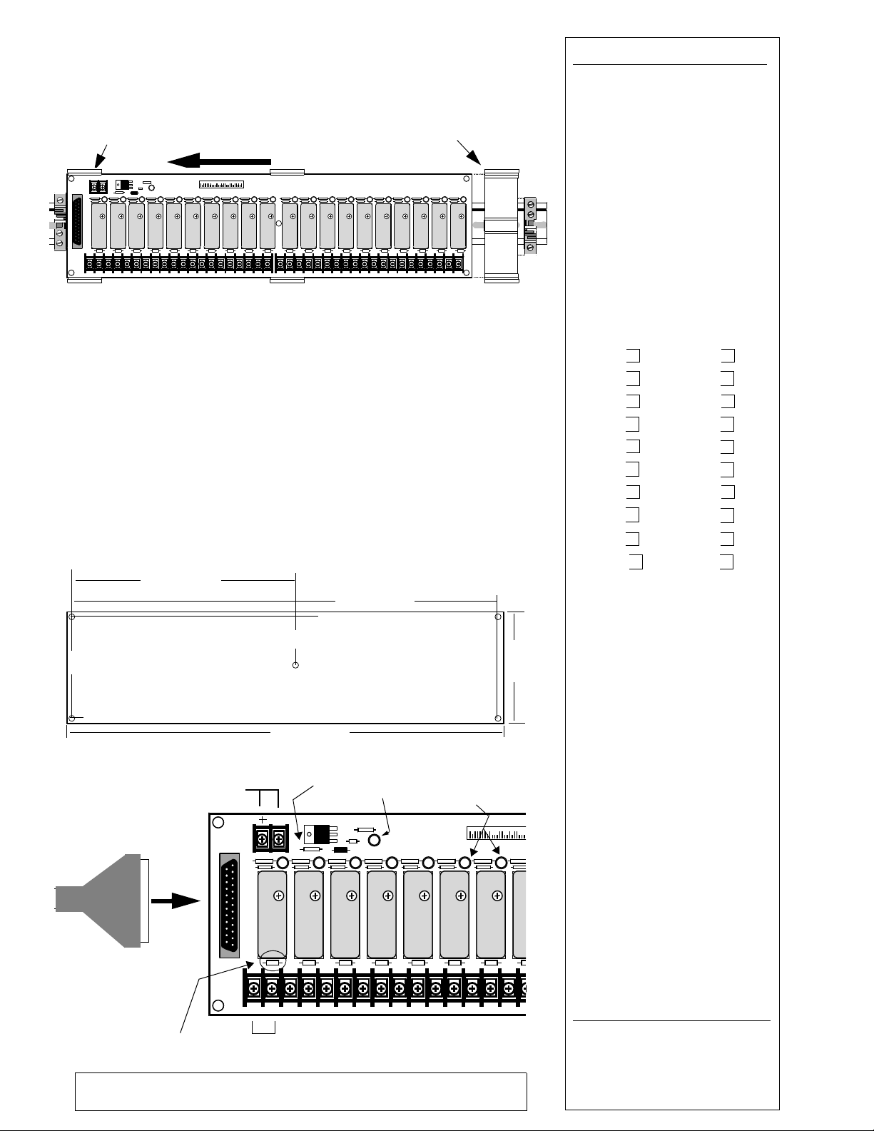
Mounting Directly to a Panel
There are four #6-sized holes (0.156” (4mm)) provided at the corners and one
in the center for mounting using stand-offs directly to a flat surface. The following illustrates the mounting dimensions of the module.
Output
4.3”
(108)
Status
LEDs
3.88 “ (98)
25-pin D Cable
from DO80-LED
or DM-20 Module
8.05 “ (204)
24VDC *
Connection
(52)
2.05”
16.1 “ (409)
Main Power
Fuse
15.7 “ (399)
LED
DIO-20 Specifications
Power: 24VDC + 10% -15%
See front page for current requirements
Input: 25-pin D connector
Input Connector Pinout:
1I/O 1
2I/O 2
3I/O 3
.
.
.
20 I/O 20
21-25 GND
Fuse Ratings:
Main Power: 1A@125V
Output: 5A@250V
I/O Connector Pinout:
1 I/O 1 21 I/O 11
2 I/O 1 22 I/O 11
3 I/O 2 23 I/O 12
4 I/O 2 24 I/O 12
5 I/O 3 25 I/O 13
6 I/O 3 26 I/O 13
7 I/O 4 27 I/O 14
8 I/O 4 28 I/O 14
9 I/O 5 29 I/O 15
10 I/O 5 30 I/O 15
11 I/O 6 31 I/O 16
12 I/O 6 32 I/O 16
13 I/O 7 33 I/O 17
14 I/O 7 34 I/O 17
15 I/O 8 35 I/O 18
16 I/O 8 36 I/O 18
17 I/O 9 37 I/O 19
18 I/O 9 38 I/O 19
19 I/O 10 39 I/O 20
20 I/O 10 40 I/O 20
Compatible ** Modules:
Opto-22 Outputs
ODC5 60VDC @3A
ODC5A 200VDC @1A
OAC5 120VAC @3A
OAC5A 240VAC @3A
OAC5A5 120/240VAC @3A
Opto-22 Inputs
IDC24 10 -32VDC
IAC24 90 - 140VAC or VDC
IAC24A 180-240VAC
Other Manufacturers:
Crydom
Gordos
Grayhill
Potter & Brumfield
** These manufacturers and model numbers
represent devices that should be compatible.
Their physical and electrical specifications
appear to meet those of our product. However,
this list does not constitute an endorsement of
the product nor does it imply that the specifications listed are accurate. Ratings listed are
nominal. Refer to manufacturer’s data sheets
for limitations.
The DIO-20 can only act as an
output interface with the AEclipse
DO-80 module.
Output
Fuses
* When using an AEclipse DO-80-LED, an external 24 VDC source must be used.
For Andover Continuum installations, the DM-20 provides the 24 VDC power.
Input/Output 1
t
ical
Connection Screw Terminals
Input/Output
Schneider Electric
© 2010, Schneider Electric
One High Street, North Andover MA 01845
978-975-9600 • 978-975-9782 Fax
www.schneider-electric.com/buildings
 Loading...