

Schneider Electric atv61 Multi pump [ EN]
Altivar 61
Pump switching card
User’s manual
VW3 A3 502
10/2011
1765272
www.schneider-electric.com


Contents
Important information _________________________________________________________________________________________ 4
Before you begin_____________________________________________________________________________________________ 5
Documentation structure_______________________________________________________________________________________ 6
Description _________________________________________________________________________________________________ 7
Description of the terminals _________________________________________________________________________________ 8
Characteristics ___________________________________________________________________________________________ 9
Data backup battery ______________________________________________________________________________________ 10
Operating Principle__________________________________________________________________________________________ 11
General________________________________________________________________________________________________ 11
Choosing a variable speed pump____________________________________________________________________________ 12
Choosing an auxiliary pump (fixed speed) __________________________________________________________________ ___ 12
Operation using limited relative operating time__________________________________________________________________ 12
Special cases ____________________________________________________________________________________ _______ 12
Selecting the operating mode_______________________________________________________________________________ 13
Controlling an auxiliary pump_______________________________________________________________________________ 13
"Sleep" function/"Wake up" function__________________________________________________________________________ 13
Compensation for loss of head (up to the version V1.1IE02)_______________________________________________________ 14
Compensation for loss of head (up to the version V1.1IE02) (continued) _________________________________ ____________ 15
Compensation for loss of head (from the version V1.2IE02) _______________________________________________________ 16
Compensation for loss of head (from the version V1.2IE02) (continued)______________________________________________ 17
Menus - Parameter Setting____________________________________________________________________________________ 18
Using the graphic display terminal or the setup software, in "connected to drive" mode __________________________________ 18
[1.14 Multi pump] (En -) menu ______________________________________________________________________________ 18
Parameters in the [1.14 Multi pump] (En -) menu________________________________________________________________ 20
Architecture of the booster station ___________________________________________________________________________ ___ 22
Connection diagrams ___________________________________________________ _____________________________________ 23
Setup ____________________________________________________________________________________________________ 26
1765272 10/2011 3
Important information
The presence of this symbol on a danger or warning label indicates that there is a risk of electrocution, which can cause
bodily injury if the instructions are not followed.
This is the symbol for a safety warning. It warns you of a potential danger of bodily injury. Follow all the safety instructions
accompanying this symbol to avoid any situation that can result in injury or death.
PLEASE NOTE
Please read these instructions carefully and examine the device in order to familiarize yourself with it before installation, operation or
maintenance. The specific messages which follow can appear in the documentation or on the device. They warn you of potential dangers
or draw your attention to information which can clarify or simplify a procedure.
DANGER
DANGER indicates a dangerous situation resulting in death, se rious injury or equipment damage.
WARNING
WARNING indicates a situation involving risks that can cause death, serious injury or equipment damage.
CAUTION
CAUTION indicates a potentially dangerous situation that can result in bodily injury or equipment damage.
IMPORTANT NOTE
The maintenance of electrical equipme nt must only p erformed by qualif ied personnel. Schneider Electric c an in no way be held responsible
for the consequences of using this documentatio n. Thi s document is n ot intend ed t o be us ed as a gui de b y person s who ha ve recei ved no
training.
© 2011 Schneider Electric. All rights reserved.
4 1765272 10/2011

Before you begin
Read and understand these instructions before performing any procedure on this drive.
DANGER
RISK OF DANGEROUS VOLTAGE
• Read and understand this manual in full before installing or operating the variable speed drive. Installation, adjustment, repair, and
maintenance must be performed by qualified personnel.
• The user is responsible for compliance with all international and na ti onal el ect rical sta ndards in force conc ernin g protect ive grounding
of all equipment.
• Many parts of this variable speed drive, including the printed circuit boards, operate at the line voltage. DO NOT TOUCH.
Use only electrically insulated tools.
• DO NOT touch unshielded components or terminal strip screw connections with voltage present.
• DO NOT short across terminals PA and PC or across the DC bus capacitors.
• Install and close all the covers before applying power or starting and stopping the drive.
• Before servicing the variable speed drive
- Disconnect all power.
- Place a "DO NOT TURN ON" label on the variable speed drive disconnect.
- Lock the disconnect in the open position.
• Disconnect all power including external control power that may be present before servicing the drive. Wait for the charging LED to go
off. WAIT 15 MINUTES for the DC bus capacitors to discharge. Then follow the procedure for measuring the DC bus voltage given in
the Installation Manual. The drive LEDs are not accurate indicators of the absence of DC bus voltage.
Failure to follow these instructions will result in death, serious injury or equipment damage.
CAUTION
DAMAGED EQUIPMENT
Do not install or operate any drive that appears damaged.
Failure to follow this instruction can result in bodily injury and/or equipment damage.
1765272 10/2011 5

Documentation structure
Installation Manual
This manual describes:
• How to assemble the drive
• How to connect the drive
Programming manual
This manual describes:
• The functions
• The parameters
• Use of the drive terminal (integrated display terminal and graphic display terminal).
Communication Parameters Manual
This manual describes:
• The drive parameters with specific information (addresses, formats, etc.) for use via a bus or communication network
• The operating modes specific to communication (state chart)
• The interaction between communication and local control
Communication bus and network manuals (Modbus®, CANopen®, Ethernet™, Profibus®,
INTERBUS, DeviceNet™, etc.)
These manuals describe:
• Connection to the bus or network
• Configuration of the parameters specific to communication via the integrated display terminal or the graphic display terminal
• Diagnostics
• Software setup
• The protocol communication services
Altivar 38 compatibility manual
This manual describes the differences between the Altivar 61 and the Altivar 38.
It explains how to replace an Altivar 38, including how to replace drives communicating on a bus or network.
6 1765272 10/2011

Description
1 23
4
5
6
1 RJ45 connector (not used)
2 9-way male SUB-D connector for connection to the CANopen bus (not used)
3 Connector with removable screw terminals, 6 contacts at intervals of 3.81 for the
24 V c power supply and 4 logic inputs.
4 3 connectors with removable screw terminals, 6 contacts at intervals of 3.81 for 6logic inputs,
6 logic outputs, 2 analog inputs, 2 analog outputs and 2 commons. Some inputs and outputs are
not used, as detailed on the next page.
5 5 LEDs, comprising:
• 1 to indicate the presence of the 24 V c power supply
• 1 to indicate a program execution fault
• 2 to indicate the CANopen bus communication status
• 1 controlled by the application program.
6 Block of 4 configuration switches (not used)
1765272 10/2011 7
Hardware setup
LI55
LI60
LI59
LI58
LI57
LI56
LO51
LO56
LO55
LO54
LO53
LO52
AI51
AO52
COM
AO51
AI52
COM
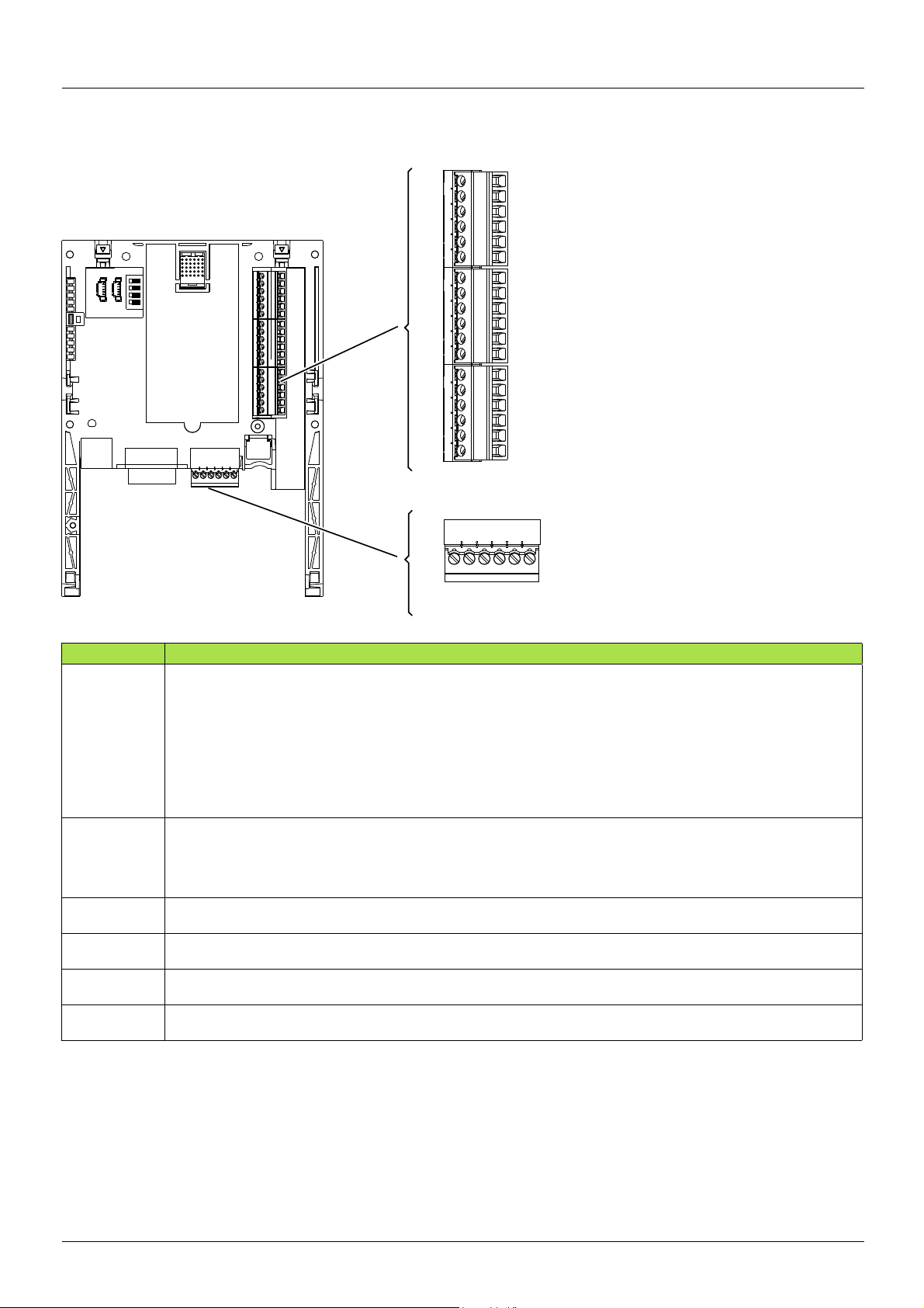
Description of the terminals
Terminals Function
24V Power supply for the pump switching card, logic outputs and analog outputs.
If allowed by the power consumption table (for example if outpu ts are not be ing used), the pump swi t ching card can be
powered by the 24 V
If you are using an external power supply:
• The pump switching card must be turned on before the drive is turned on, or at the same time as the drive is
turned on.
If this order is not followed, the drive will lock in a card fault (ILF). This fault cannot be reset, and the only way to
acknowledge it is to turn off the drive.
• Catalog number for a Schneider-Electric power supply (24 V
COM
(3 terminals)
LI51 to LI60 24 V
LO51 to LO56 24 V
AI51 and AI52 0 ... 20mA analog inputs
AO51 and AO52 0 ... 20mA analog outputs
Common ground and electrical 0V of the pump switching card power supply, logic inputs, (LI
inputs (AI
This ground and electrical 0V are common with the drive ground and electrical 0V. There is therefore no point in
connecting this terminal to the 0V terminal on the drive control terminals.
LI56 to LI60 = Not used
LO56 = Not used
Not used
Not used
pp) and analog outputs (AOpp).
c logic inputs
c logic outputs
c power supply in the drive.
c, 2A): ABL7 RE 24 02.
pp), outputs (LOpp), analog
8 1765272 10/2011

Hardware setup
Characteristics
Electrical characteristics
Power supply Voltage V 24 c (min. 19, max. 30)
Current
consumption
Logic inputs LI51…LI60 Impedance 4.4 kΩ
Logic outputs LO51…LO56 Six 24 V c logic outputs, positive logic open collector type (source),
I/O connection Type of contact Screw, at intervals of 3.81 mm
Lithium battery Life 8 years
Maximum A 2
No-load mA 80
Using logic output mA 200 maximum (1)
Maximum voltage: 30 V c
Switching thresholds:
State 0 if y 5 V or logic input not wired
State 1 if u 11 V
Common point for all the card I/O (2)
compatible with level 1 PLC, standard IEC 65A-68
Maximum switching voltage: 30 V
Maximum current: 200 mA
Common point for all the card I/O (2)
Maximum capacity mm21.5 (AWG 16)
Tightening torque
Nm
0.25
2
(1)If the power consumption table does not exceed 200 mA, this card can be powered by the drive. Otherwise, an external 24 V c power supply must be used.
(2)This common point is also the drive 0 V (COM).
1765272 10/2011 9
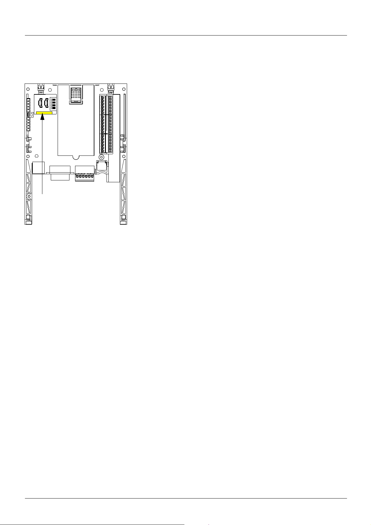
Hardware setup
When installing the pump switching card in the drive, make sure that this battery is
present. It takes the form of a rectangular block clipped onto the non-volatile RAM (see
schematic opposite).
The battery life is 8 years.
The battery has a realtime clock for timestamping faults.The precisio n of the clock is 3.76
seconds per day
The date and time on this clock are checked and set from a special sub-menu in the
[1.14 - Multi pump] (En -) customizable menu in the graphic display terminal.
The date and time need to be set on receipt of the pump switching card, or after replacing
its lithium battery.
The lithium battery must only be replaced when the drive and the pump switching card
are turned off.
During this operation, the data saved in the NVRAM (4 Kwords) is lost.
Lithium
battery
Data backup battery
The pump switching card has a non-volatile RAM (NVRAM) which is needed to store variables. A lithium battery is mounted on this
non-volatile RAM to avoid this data being lost when the card is turned off.
Important:
Spare part reference does not exist for the battery because of a problem of time storage. So, it is necessary to order it by your-self. The
reference of the baterry is TIMEKEEPER SNAPHAT M4T28-BR12SH1 (48mAh).
10 1765272 10/2011
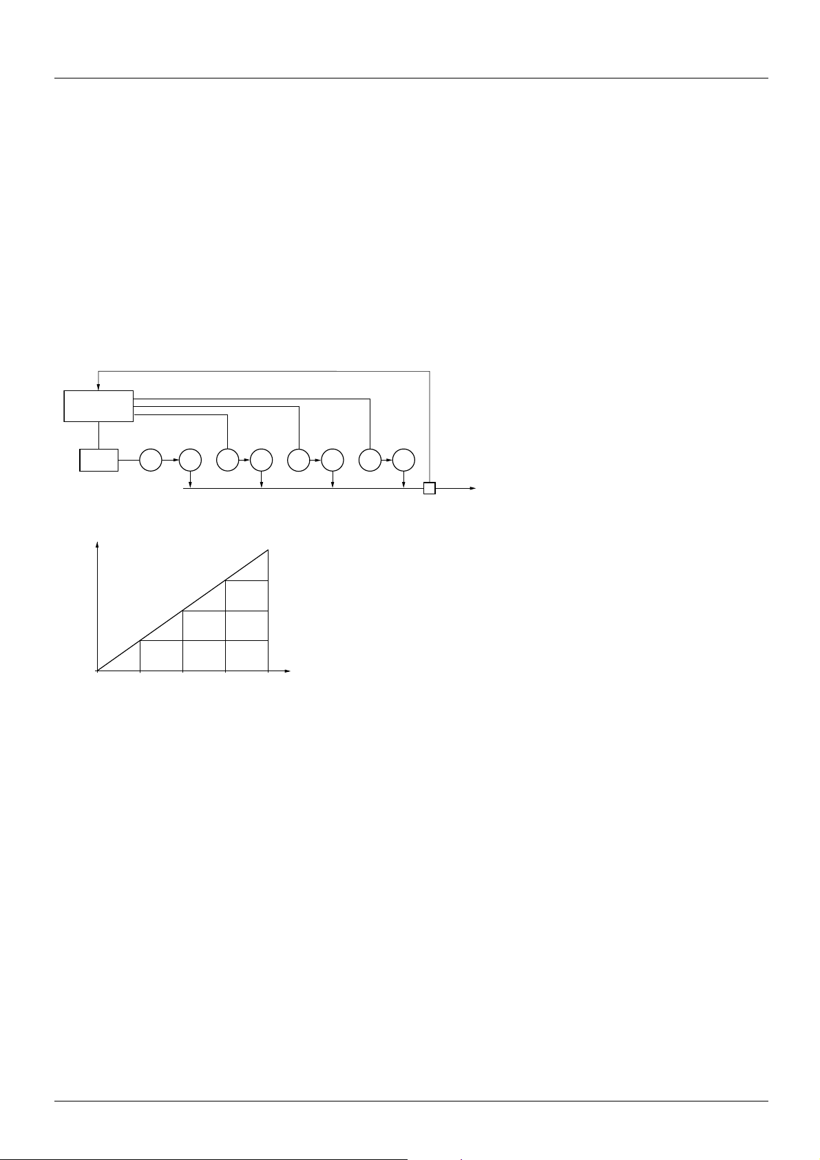
Operating Principle
P1M1 P2M2 P3M3
PVMATV 61
2310
P3
P2 P2
P1 P1 P1
PV
PV
PV
PV
4
Control of auxiliary pumps
Card
VW3A3502
Number of pumps
Flow
rate
PV: variable pump
P1, P2, P3: auxiliary pumps
Flow rate at
constant
pressure
Pressure
measurement
General
The main object is to control a complete pumping installation usi ng a single ATV61 drive, providing:
- Constant pressure in the system whatever the flow rate
- A simple method for setting up and diagnosing the installation via the ATV61.
The system is operated using several fixed speed p umps (maximum of 4 ), and one v ariable speed p ump, which is unabl e to provide the full
flow range required on its own. A PI regulator is used for pump control. The pressure sensor provides system feedback.
To avoid systematic wear of the same pumps, a function is provided that allows switching of the pumps according to their operating time.
The variable pump can also be included in this changeover procedure.
The variable speed pump (PV) is called a variable pump.
The fixed speed pumps are called auxiliary pumps.
Application example with 3 fixed pumps:
The auxiliary pumps are turned on and off according to the flow rate required by the installation. The variable pump is controlled so as to
ensure continuity in the flow rate variations.
1765272 10/2011 11
 Loading...