

Schneider Electric ATV61, ATV71 Controller inside [EN]
Altivar 61 / 71
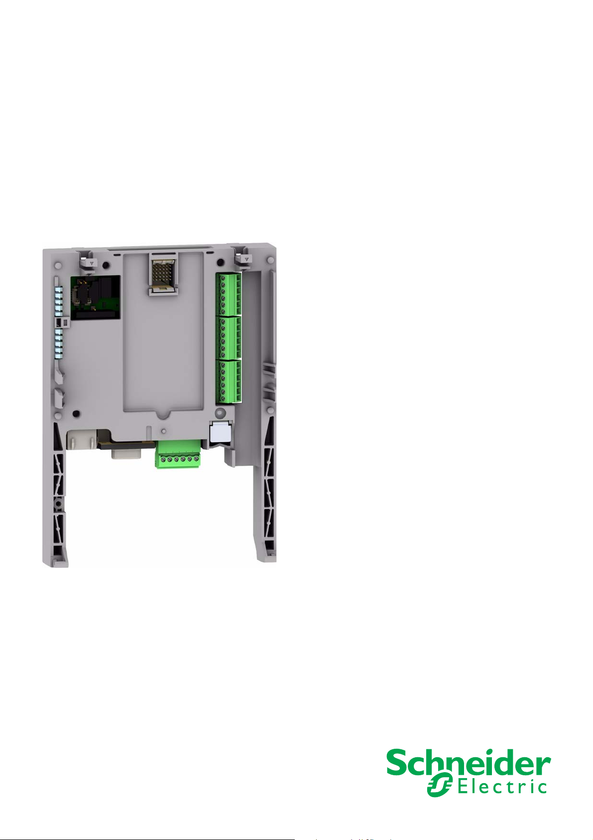
"Controller Inside" Card
User’s manual
VW3 A3 501
11/2010
1757062
www.schneider-electric.com


Contents
While every precaution has been taken in the preparation of this document,
Schneider Electric SA assumes no liability for any omissions or errors i t may contain,
nor for any damages resulting from the application or use of the information herein.
The products and options descr ibed in th is document may be changed or modifi ed at
any time, either from a technical point of view or in the way they are operated.
Their description can in no way be considered contractual.
Before you begin_____________________________________________________________________________________________ 4
Documentation structure_______________________________________________________________________________________ 5
Introduction_________________________________________________________________________________________________ 6
Presentation _____________________________________________________________________________________________ 6
Description ______________________________________________________________________________________________ 6
Dialog __________________________________________________________________________________________________ 7
Master CANopen communication_____________________________________________________________________________ 7
Communication with a PLC ___________________________________________ ______________________________________ 7
Clock______________________________________________________________________ _____________________________ 8
Programming ____________________________________________________________________________________________ 8
Hardware setup _____________________________________________________________________________________________ 9
Receipt _________________________________________________________________________________________________ 9
Installing the card in the drive________________________________________________________________________________ 9
Description of terminals _____________ ______________________________________________________________________ 10
Characteristics __________________________________________________________________________________________ 11
Schemes_______________________________________________________________________________________________ 12
Connection to a CANopen bus______________________________________________________________________________ 13
Example of connection to a CANopen bus_____________________________________________________________________ 14
Connecting the "Controller Inside" card to a PC_________________________________________________________________ 15
Data backup battery ______________________________________________________________________________________ 16
Configuration ______________________________________________________________________________________________ 17
Configuring the switches___________________________________________________________________________________ 17
Diagnostics____________________________________________________________________________________ ____________ 18
LEDs__________________________________________________________________________________________________ 18
I/O monitoring___________________________________________________________________________________________ 19
Card fault ______________________________________________________________________________________________ 20
Operation using the graphic display terminal ______________________________________________________________________ 21
Factory-loaded program___________________________________________________________________________________ 21
Example of a special program ______________________________________________________________________________ 23
Operation using the integrated display terminal ____________________________________________________________________ 24
Factory-loaded program___________________________________________________________________________________ 24
Special program _________________________________________________________________________________________ 24
1757062 11/2010 3
Before you begin
Read and understand these instructions bef ore performing any procedure on this drive.
DANGER
HAZARDOUS VOLTAGE
• Read and understand the Installation manual before installing or operating the Altivar 61 / 71 drive. Installation,
adjustment, repair, and maintenance must be performed by qualified personnel.
• The user is responsible for compliance with all international and national electrical standards in force concerning
protective grounding of all equipment.
• Many parts of this variable speed drive, including the printed circuit boards, operate at the line voltage.
DO NOT TOUCH.
Use only electrically insulated tools.
• DO NOT touch unshielded components or terminal strip screw connections with volta ge present.
• DO NOT short across terminals PA and PC or across the DC bus capacitors.
• Install and close all the covers before applying power or starting and stopping the drive.
• Before servicing the variable speed drive
- Disconnect all power
- Place a “DO NOT TURN ON” label on the variable speed drive disconnect
- Lock the disconnect in the open position
• Disconnect all power including external control power that may be present before servicing the drive.
WAIT 15 MINUTES to allow the DC bus capacitors to discharge. Then follow the DC bus voltage measurement
procedure given in the installation manual to verify that the DC voltage is less than 45 VDC. The drive LEDs are not
accurate indicators of the absence of DC bus voltage.
Electric shock will result in death or serious injury.
CAUTION
DAMAGED EQUIPMENT
Do not install or operate any drive that appears damaged.
Failure to follow this instruction can result in equipment damage.
4 1757062 11/2010

Documentation structure
Installation manual
This manual describes:
• Assembly
• How to connect the drive
Programming manual
This manual describes:
• The functions
• The parameters
• How to use the drive display terminal (integrated display terminal and graphic display terminal)
Communication parameters manual
This manual describes:
• The drive parameters with specific information (addresses, formats, etc) for use via a bus or communication network
• The operating modes specific to communication (state chart)
• The interaction between communication and local control
Modbus®, CANopen®, Ethernet™, Profibus™, INTERBUS, Uni-Telway, DeviceNet®, Modbus® Plus,
FIPIO...
These manuals describe:
• Connection to the bus or network
• Configuration of the communication-specific parameters via the integrated display terminal or the graphic display terminal
• Diagnostics
• Software setup
• The communication services specific to the protocol
Altivar 58/58F compatibility manual
This manual describes the differences between the Altivar 71 and the Altivar 58/58F.
It explains how to replace an Altivar 58 or 58F, including how to replace drives communicating on a bus or network.
Altivar 38 compatibility manual
This manual describes the differences between the Altivar 61 and the Altivar 38.
It explains how to replace an Altivar 38, including how to replace drives communicating on a bus or network.
1757062 11/2010 5
Introduction
1 23
4
5
6
Presentation
The “Controller Inside” programmable card is used to adapt the variable speed drive to specific applications by integrating control system
functions.
Various predefined configurable applications are sold by Schneider-Electric and its partners.
The PS 1131 software workshop for PC is used for programming and debugging new applica tions, qui ckly and in a n open-ende d manner.
It is not possible to transfer the program from the card to the PC, which enables us to protect our know-how.
Only one “Controller Inside” pr ogrammable card can be instal led in the Altivar 61 or Altivar 7 1 drive. It can be combined with ano ther option card
(I/O extension or communication). Consult the tables summarizing the possible combinations: drives, options and accessories,
see catalogue.
The “Controller Inside” programmable card has:
• 10 logic inputs, 2 of which can be used for 2 counters or 4 of which can be used for 2 incremental encoders
• 2 analog inputs
• 6 logic outputs
• 2 analog outputs
• A master port for the CANopen bus
• A PC port for programming with the PS 1131 software workshop
• If the power consumption table does not exceed 200 mA, this card can be powered by the drive. Otherwise, an external 24 V c power
supply must be used.
The “Controller Inside” programmable card can also use:
• The drive I/O
• The I/O extension card I/O
• The encoder interface card points counter
• The drive parameters (speed, current, torque, etc)
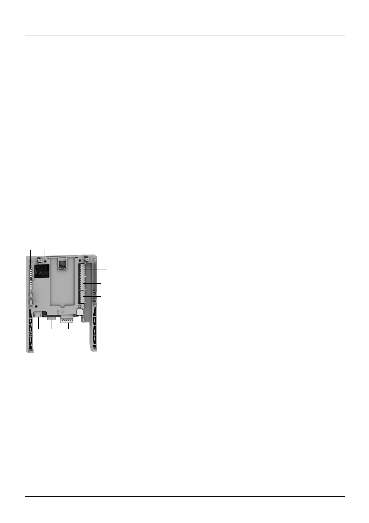
Description
1 RJ45 connector for connecting the PS 1131 software workshop via an RS 485 serial link.
Connection to the PC is via a cable and an RS 232/RS 485 converter included in the PCSoftware for PC connection kit, VW3 A8 106.
2 9-way male SUB-D connector for connection to the CANopen bus.
3 Connector with removable screw terminals, 6 contacts at intervals of 3.81 for the
24 V c power supply and 4 logic inputs.
4 3 connectors with removable screw terminals, 6 contacts at intervals of 3.81 for 6 logic
inputs, 6 logic outputs, 2 analog inputs, 2 analog outputs and 2 commons.
5 5 LEDs, comprising:
• 1 to indicate the presence of the 24 V c power supply
• 1 to indicate a program execution fault
• 2 to indicate the CANopen bus communication status
• 1 controlled by the application program
6 Block of 4 configuration switches
6 1757062 11/2010
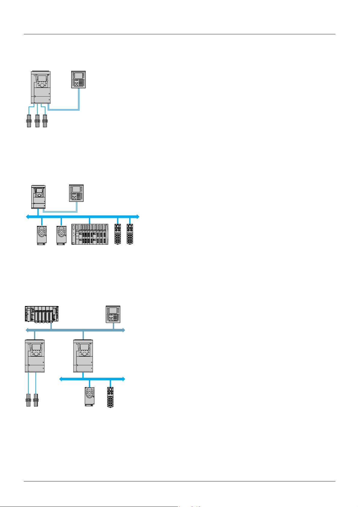
Introduction
Sensors
XBT Magelis
ATV 61 / 71
Modbus bus
Independent machine with multiwire system
ATV 31
ATV 31 Advantys STB
distributed I/O
FTB 1CN
XBT Magelis
CANopen bus
Independent machine with CANopen bus
ATV 61 / 71
Modbus bus
Sensors ATV 31 FTB 1CN
CANopen bus
Ethernet TCP/IP network
Premium
ATV 61 / 71
ATV 61 / 71
XBT Magelis
Modular machine with Ethernet TCP/IP network
Dialog
Human-machine dialog with the application programmed in the “Controller Inside”
programmable card is possible using:
• The Altivar 61 / 71 graphic display terminal
• A Magelis industrial HMI terminal connected to the drive Modbus port
• A Magelis industrial HMI terminal connected to the Ethernet TCP/IP netwo rk (if the drive is
equipped with an Ethernet TCP/IP communication card)
One graphic terminal menu is dedicated to the “Controller Inside” programmable card. This
menu can be customized by the card program according to the application.
Any industrial HMI terminal which supports the Modbus protocol can be used to display and
modify the “Controller Inside” programmable card parameters. The card Modbus server
provides access to 2048 Kwords (% MW, etc).
Master CANopen communication
The master CANopen port on the “Controller Inside” programmable card can be
used to extend the I/O capacity (using CANopen I/O modules) and to control other
CANopen slave devices.
Communication with a PLC
The Altivar 61 / 71 drive equipped with a “Controller Inside” programmable card fits
easily into complex architectures.
Regardless of which bus or network is being used (Ethernet TCP/IP, Modbus/
Uni-Telway, FIPIO, Modbus Plus, Profibus DP, InterBus, etc), the PLC can
communicate with the “Controller Inside” progra mmable card and the drive. The periodic
variables can still be configured as required.
1757062 11/2010 7

Introduction
Clock
A clock backed up by a lithium battery makes it possible to have a log of events that have occurred. When the “Controller Inside”
programmable card is installed in the drive, the drive faults are automatically time and date-stamped without special programming.
Programming
In factory settings mode, the "Controller Inside" card only contains the clock function.
For other applications, the program must be loaded:
• By loading an existing program (procedure described in the PS 1131documentation)
• Or by loading a custom-built program, with the aid of the PS 1131 software workshop, using the function libraries dedicated to
programming the "Controller Inside" card.
In order to program the "Controller Inside" card, it is necessary to undergo training.
The PS1131 CD-Rom contains:
• This manual, already available on the CD-Rom supplied with ea ch Altivar 61 / 71
• The PS 1131 software workshop
• The online help
• The standard function library
• Program examples
• The Altivar 61 / 71 parameters manual
The standard function library contains:
• Logic functions (AND, OR, etc)
• Mathematical functions (Cos, Sin, Exp, etc)
• Functions dedicated to drives which simplify data exchanges between t he drive and the "Controller Inside" programmable card (example:
sending the speed reference)
• Functions for managing the CANopen bus
• Graphic terminal display functions
This manual does not describe programming using PS 1131.
Note: PS 1131 is also called CoDeSys.
CoDeSys V2.2 can be used on the Controller Inside for Altivar 58 (VW3A581131), but must not be used for programming the Controller
Inside for Altivar 61 / 71 (VW3 A3 501).
8 1757062 11/2010
 Loading...