

Schneider Electric ATV61, ATV71 Canopen [EN]

Altivar 61 / 71
CANopen
®
User's manual
11/2010
1755865
www.schneider-electric.com


Contents
While every precaution has been taken in the preparation of this document,
Schneider Electric SA assumes no liability for any omissions or errors it may contain,
nor for any damages resulting from the application or use of the information herein.
The products and options descr ibed in th is document may be changed or modifi ed at
any time, either from a technical point of view or in the way they are operated. Their
description can in no way be considered contractual.
Before you begin_____________________________________________________________________________________________ 4
Documentation structure_______________________________________________________________________________________ 5
Introduction_________________________________________________________________________________________________ 6
Presentation _____________________________________________________________________________________________ 6
Notation ______________________________________________ __________________________________________________ 6
Hardware setup _____________________________________________________________________________________________ 7
Installing the CANopen adapter ______________________________________________________________________________ 7
Connecting to the CANopen bus ____________________________________________________ _________________________ 8
Configuration ________________________________________ ___________________________________________________ ___ 10
Configuring the communication parameters____________________________________________________________________ 10
Control-signal configuration ________________________________________________________________________________ 11
Configuring monitored parameters___________________________________________________________________________ 14
Configuring communication fault management _________________________________________________________________ 15
Diagnostics____________________________________________________________________________________ ____________ 16
LEDs__________________________________________________________________________________________________ 16
Communication diagnostics ________________________________________________________________________________ 17
Control-signal diagnostics__________________________________________________________________________________ 19
Communication faults_____________________________________________________________________________________ 21
Software setup _____________________________________________________________________________________________ 22
Profiles ________________________________________________________________________________________________ 22
PDO (Process Data Objects) _______________________________________________________________________________ 23
SDO (Service Data Objects)________________________________________________________________________________ 26
Other available services___________________________________________________________________________________ 26
Description of identifiers taken into account____________________________________________________________________ 27
Software setup with PL7 and SyCon ____________________________________________________________________________ 28
Detailed description of services ________________________________________________________________________________ 40
NMT commands _________________________________________________________________________________________ 40
CANopen NMT state chart _________________________________________________________________________________ 41
Bootup service __________________________________________________________________________________________ 43
Synchronization object - SYNC _____________________________________________________________________________ 43
Emergency object - EMCY_______________ __________________________________________________________________ 43
PDO1 ________________________________________________ _________________________________________________ 44
PDO2 ________________________________________________ _________________________________________________ 48
PDO3 ________________________________________________ _________________________________________________ 49
SDO service ____________________________________________________________________________________________ 50
Node Guarding service____________________________________________________________________________________ 53
Heartbeat service ________________________________________________________________________________________ 55
Object dictionary____________________________________________________________________________________________ 56
Communication profile zone objects__________________________________________________________________________ 57
1755865 11/2010 3

Before you begin
Read and understand these instructions before performing any procedure with thi s drive.
DANGER
HAZARDOUS VOLTAGE
• Read and understand this manual before insta lling or operating the Alti var drive. Installation, a djustment, repair, and
maintenance must be performed by qualified personnel.
• The user is responsible for compliance with all international and national electrical standards in force concerning
protective grounding of all equipment.
• Many parts in this variable speed drive, including printed wiring boards, operate at line voltage. DO NOT TOUCH.
Use only electrically insulated tools.
• DO NOT touch unshielded components or terminal strip screw connections with volta ge present.
• DO NOT short across terminals PA and PC or across the DC bus capacitors.
• Install and close all covers before applying power or starting and stopping the drive.
• Before servicing the variable speed drive:
- Disconnect all power
- Place a "DO NOT TURN ON" label on the variable speed drive disconnect
- Lock the disconnect in the open position
• Disconnect all power including external control power that may be present before servicing the drive. WAIT 15
MINUTES for the DC bus capacitors to discharge. Then follow the DC bus voltage measurement procedure given
in the Installation Manual to verify that the DC voltage is less than 45 Vdc. The drive LEDs are not accurate indicators
of the absence of DC bus voltage.
Electric shock will result in death or serious injury
CAUTION
DAMAGED EQUIPMENT
Do not operate or install any drive that appears damaged.
Failure to follow this instruction can result in equipment damage.
4 1755865 11/2010

Documentation structure
Installation manual
This manual describes:
• How to assemble the drive
• How to connect the drive
Programming manual
This manual describes:
• The functions
• The parameters
• How to use the drive display terminal (integrated display terminal and graphic display terminal)
Communication parameters manual
This manual describes:
• The drive parameters with specific information for use via a bus or communication network
• The operating modes specific to communication (state chart)
• The interaction between communication and local control
Modbus, CANopen®, Ethernet™, Profibus, INTERBUS, Uni-Telway, FIPIO, Modbus Plus,
DeviceNet™ ... manuals
These manuals describe:
• Connection to the bus or network
• Diagnostics
• Configuration of the communication-specific parameters via the integrated display terminal or the graphic display terminal
They describe the protocol communication services in detail.
Altivar 58/58F migration manual
This manual describes the differences between the Altivar 71 and the Altivar 58/58F.
It explains how to replace an Altivar 58 or 58F, including how to replace drives communicating on a bus or network.
Altivar 38 migration manual
This manual describes the differences between the Altivar 61 and the Altivar 38.
It explains how to replace an Altivar 38, including how to replace drives communicating on a bus or network.
1755865 11/2010 5

Introduction
Presentation
The CANopen protocol is available on the Altivar speed drive via a VW3 CAN A71 adapter, which must be ordered separately.
The CANopen adapter features a CANopen-compliant 9-way male SUB-D connector referred to as the “CANopen port” in this manual.
The CANopen port on the Altivar can be used for the following functions:
• Configuration
• Adjustment
• Control
• Monitoring
This manual describes how to set up the Altivar drive on CANopen and also describes the CANopen servi ces that are available on this drive.
Notation
Drive terminal displays
The graphic display terminal menus are shown in square brackets.
Example: [1.9 COMMUNICATION].
The integrated 7-segment display terminal menus are shown in round brackets.
Example: (COM-).
Parameter names are displayed on the graphic display terminal in square brackets.
Example: [Fallback speed]
Parameter codes are displayed on the integrated 7-segment display terminal in round brackets.
Example: (LFF).
Formats
In this manual, hexadecimal values are written as follows: 16#.
6 1755865 11/2010
Hardware setup
Modbus terminal port (HMI)
Example: ATV71HU22M3
VW3 CAN A71
CANopen
adapter
Modbus network port
8........................1
CAN _H -7-
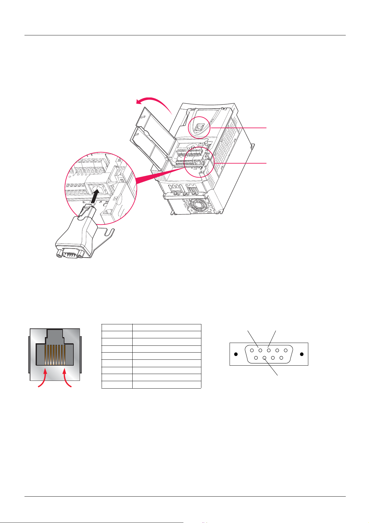
Installing the CANopen adapter
Install the VW3 CAN A71 CANopen adapter in the RJ45 port located on the drive's control terminals.
Note: This adapter MUST be screwed to the drive via its CANopen bus metal groun ding plate.
Modbus network port pinout
View from underneath
Pin Signal
(1)Modbus signal
(2)Power supply for an RS232/RS485 converter (to PC-Software)
1 CAN_H
2 CAN_L
3 CAN_GND
4D1 (1)
5D0 (1)
6 Not connected
7VP (2)
8 Common (1)
Pinout of 9-way male SUB-D connector on
CANopen adapter
CAN_L -2- CAN_GND -3-
1755865 11/2010 7
Hardware setup
2
3
5
4
1
5 5 6
CANopen
TSX CPP 110
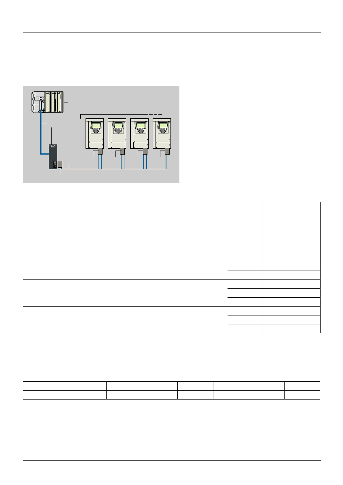
Connecting to the CANopen bus
The diagram below illustra tes an e xampl e conf ig uration co mprisi ng f our Altivar drives connec ted to a TSX Premium mast er PLC fitted with
a TSX CPP 110 CANopen master PCMCIA card.
Connection accessories should be ordered separately (please consult our cat alogs). See also below.
1. TSX Premium PLC + TSX CPP 110 CANopen master
PCMCIA card
2. Drop cable and cable connector supplied with TSX CPP 110
card
3. TSX CAN KCDF 180T 9-way female SUB-D connector with
active line terminator
4. TSX CAN C
100 or 300 m
5. VW3 CAN A71 CANopen adapter + VW3 CAN KCDF 180T
9-way female SUB-D connector with deactivated line
terminator
6. VW3 CAN A71 CANopen adapter + VW3 CAN KCDF 180T
9-way female SUB-D connector with active line terminator
••• CANopen cable, available in lengths of 50,
Description Length (m) Catalog number
CANopen adapter to be installed
in the RJ45 port on the drive's control terminals.
The adapter provides a 9-way male SUB-D connector conforming to the CANopen standard
(CIA DRP 303-1).
CANopen connector (1)
9-way female SUB-D connector with line terminator (can be deactivated)
CANopen cables LSZH
CE certification. Low smoke, halogen free and flame retardant (IEC 60332-1).
CANopen cables UL / IEC 60332-2
UL certification. Non flame propagating (IEC 60332-2).
CANopen cables flexible LSZH HD
For heavy duty or mobile applications. Low smoke, halogen free and flame retardant (IEC
60332-1). Oil resistant.
(1) For ATV 71H
TSX CAN KCDF 180T connector.
•••M3, ATV 71HD11M3X, HD15M3X and ATV 71H075N4 to HD18N4 drives, this connector can be replaced by the
– VW3 CAN A71
– VW3 CAN KCDF 180T
50 TSX CAN CA 50
100 TSX CAN CA 100
300 TSX CAN CA 300
50 TSX CAN CB 50
100 TSX CAN CB 100
300 TSX CAN CB 300
50 TSX CAN CD 50
100 TSX CAN CD 100
300 TSX CAN CD 300
Length of CANopen bus
The maximum length of the bus depends on the communication speed:
Communication speed 20 kbps 50 kbps 125 kbps 250 kbps 500 kbps 1000 kbps
Maximum length of bus 2500 m 1000 m 500 m 250 m 100 m 25 m
These lengths are for a CANopen bus and take into account actual dispersions on the components as well as when certain devices are
optocoupled to the bus.
Schneider-Electric will not accept liability for longer lengths specified in other documents.
8 1755865 11/2010
Hardware setup
7
5
10
max.
1
2
3
4
5
6
1
2
3
4
5
6
7
8
9
CAN-GND
CAN-L
CAN-H
CAN-L
CAN-H
CAN-GND
R1
S1
X1
X2
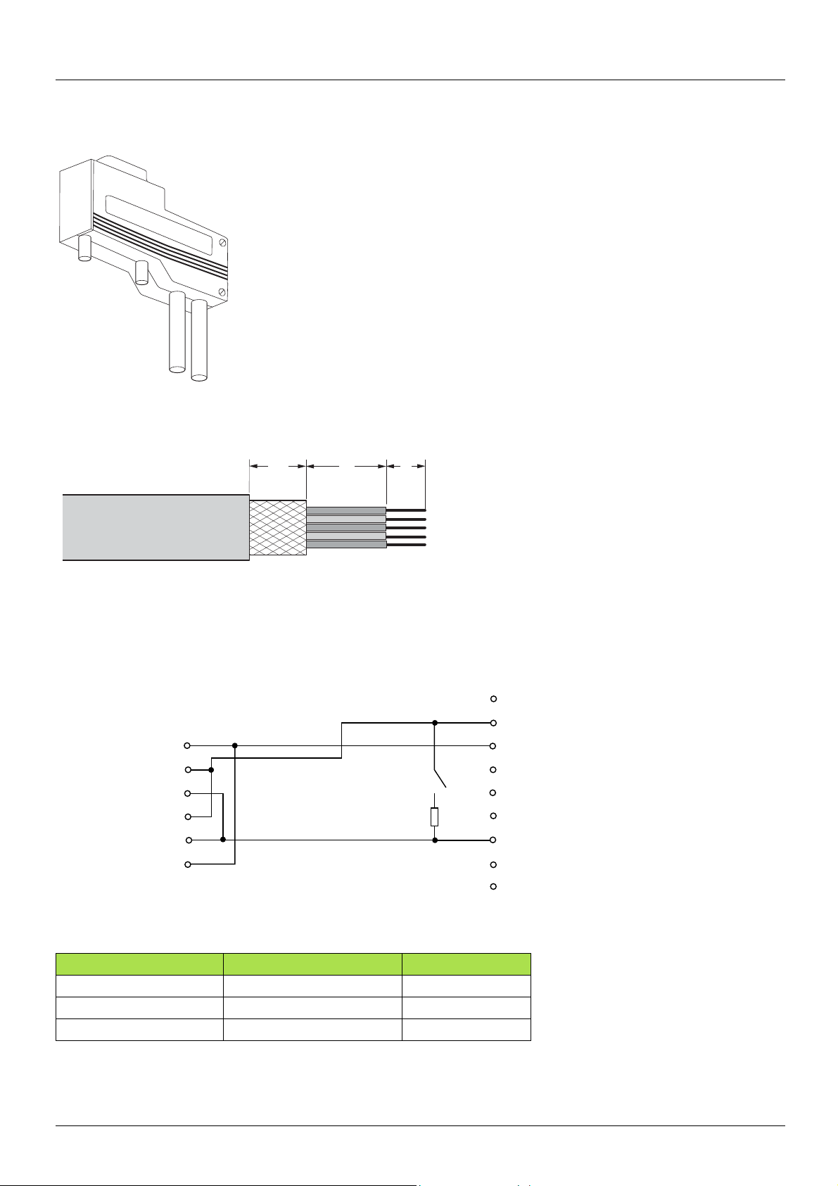
CANopen connector (VW3 CAN KCDF 180T)
How to strip the CANopen cable
Schematic
X1 = Internal screw terminal
X2 = 9-way female SUB-D
1, 6 3 CAN_GND
2, 4 2 CAN_L
3, 5 7 CAN_H
X1 = Internal screw terminal X2 = 9-way female SUB-D Signal
1755865 11/2010 9

Configuration
Configuring the communication parameters
The configuration of the CANopen communication functions on the Altivar is accessed via the [1.9 - COMMUNICATION] (COM-), menu (
[CANopen] (CnO-) submenu) on the graphic display terminal or integrated display terminal.
Note:
The configuration can only be modified when the motor is stopped and the drive locked.
In order for modifications to take effect, the drive must be shut down then restarted.
Parameter Possible values Terminal display Default value
[CANopen address] (AdCO) CANopen deactivated
1 to 127
[CANopen bit rate] (bdCO) 00- [20 kbps] (20) (1)
0050 kbps [50 kbps] (50)
0 125 kbps [125 kbps] (125)
0 250 kbps [250 kbps] (250)
0 500 kbps [500 kbps] (500)
1 000 kbps [1000 kbps] (1M)
[OFF] (0FF)
[1] (1)....[127] (127)
[OFF] (0FF)
[125 kbps] (125)
In this user’s manual, the [CANopen address] (AdC0) parameter is referred to as the "NODE-ID".
Set this parameter to its default value, (0FF), to deactivate CANopen communication on the Altivar.
To activate CANopen communication on the Altivar, write a value other than zero to the [CANopen address] (AdC0) parameter.
The value of the [CANopen bit rate] (bdC0) parameter must correspond to the communication speed of all other devices connected to the
CANopen bus.
(1)Do not select [20 kbps] (20), possible malfunction.
10 1755865 11/2010

Configuration
Control-signal configuration
Numerous control-signal configurations are possible. Please consult the Programming Manual.
The following configurations are just some of the possibili ties available.
Control via CANopen in I/O profile
The command and target come from CANopen.
The command is in I/O profile.
Configure the following parameters:
Parameter Value Comment
Profile I/O profile The run command is simply obtained by bit 0 of the control word.
Target 1 configuration CANopen The target comes from CANopen.
Command 1 configuration CANopen The command comes from CANopen.
Configuration via the graphic display terminal or the integrated display terminal:
Menu Parameter Value
[1.6 - COMMAND] (CtL-) [Profile] (CHCF) [I/O profile] (IO)
[Ref. 1 channel] (Fr1) [CANopen] (CAn)
[Cmd channel 1] (Cd1) [CANopen] (CAn)
Control via CANopen or the terminals in I/O profile
Both the command and target come from CANopen or the terminals. Input LI5 at t he terminals is used t o switch between CANop en and the
terminals.
The command is in I/O profile.
Configure the following parameters:
Parameter Value Comment
Profile I/O profile
Target 1 configuration CANopen Target 1 comes from CANopen.
Target 1B configuration Analog input 1 on the terminals Target 1B comes from input AI1 on the terminals.
Target switching Input LI5 Input LI5 switches the target (1
Command 1 configuration CANopen Command 1 comes from CANopen.
Command 2 configuration Terminals C ommand 2 comes from the terminals.
Command switching Input LI5 Input LI5 switches the command.
Target 1B is connected to the functions (summing, PID, etc.) that remain active, even after switching.
Configuration via the graphic display terminal or the integrated display terminal:
Menu Parameter Value
[1.6 - COMMAND] (CtL-) [Profile] (CHCF) [I/O profile] (IO)
[Ref. 1 channel] (Fr1) [CANopen] (CAn)
[Cmd channel 1] (Cd1) [CANopen] (CAn)
[Cmd channel 2] (Cd2) [Terminals] (tEr)
[Cmd switching] (CCS) [LI5] (LI5)
[1.7 APPLICATION FUNCT.] (FUn-) [REFERENCE
SWITCH.]
[Ref. 1B chan] (Fr1b) [AI1] (AI1)
[Ref 1B switching] (rCb) [LI5] (LI5)
The run command is simply obtained via bit 0 of the control
word.
↔ 1B).
1755865 11/2010 11

Configuration
Control via CANopen in DSP402 profile
The command and target come from CANopen.
The command is in DSP402 profile (not separate mode).
Configure the following parameters:
Parameter Value Comment
Profile DSP402 profile not separate
Target 1 configuration CANopen The command and the target come from CANopen.
Configuration via the graphic display terminal or the integrated display terminal:
Menu Parameter Value
[1.6 - COMMAND] (CtL-) [Profile] (CHCF) [Not separ.] (SIM) (factory setting)
[Ref. 1 channel] (Fr1) [CANopen] (CAn)
The run commands are in DSP402 profile, the command and the
target come from the same channel.
Control via CANopen or the terminals in DSP402 profile
Both the command and target come from CANopen or the terminals. Input LI5 at t he terminals is used t o switch between CANop en and the
terminals.
The command is in DSP402 profile (not separate mode).
Configure the following parameters:
Parameter Value Comment
Profile DSP402 profile not separate
Target 1 configuration CANopen Target 1 comes from CANopen.
Target 2 configuration Analog input 1 on the terminals Target 2 comes from input AI1 on the terminals.
Target switching Input LI5 Input LI5 switches the target (1
Warning: Target 2 is directly connected to the drive reference limit. If switching is performed, the functions that affect the reference
(summing, PID, etc) are inhibited.
Configuration via the graphic display terminal or the integrated display terminal:
Menu Parameter Value
[1.6 - COMMAND] (CtL-) [Profile] (CHCF) [Not separ.] (SIM)
The run commands are in DSP402 profile, the command and the
target come from the same channel.
↔ 2) and the command.
[Ref. 1 channel] (Fr1) [CANopen] (CAn)
[Ref. 2 channel] (Fr2) [AI1] (AI1)
[Ref. 2 switching] (rFC) [LI5] (LI5)
12 1755865 11/2010

Configuration
Command in DSP402 profile via CANopen and target switching at the terminals
The command comes from CANopen.
The command comes either from CANopen or from the terminals. Inp ut LI5 at the te rmina ls is us ed to swit ch the targ et bet ween CANopen
and the terminals.
The command is in DSP402 profile (separate mode).
Configure the following parameters:
Parameter Value Comment
Profile Separate DSP402 profile
Target 1 configuration CANopen Target 1 comes from CANopen.
Target 1B configuration Analog input 1 on the terminals Target 1B comes from input AI1 on the terminals.
Target switching Input LI5 Input LI5 switches the target (1
Command 1 configuration CANopen Command 1 comes from CANopen.
Command switching Channel 1 Channel 1 is the command channel.
Target 1B is connected to the functions (summing, PID, etc.), which remain active, even after switching.
The run commands are in DSP402 profile, the command and the
target can come from different channels.
↔ 1B).
Configuration via the graphic display terminal or the integrated display terminal:
Menu Parameter Value
[1.6 - COMMAND] (CtL-) [Profile] (CHCF) [Separate] (SEP)
[Ref. 1 channel] (Fr1) [CANopen] (CAn)
[Cmd channel 1] (Cd1) [CANopen] (CAn)
[Cmd switching] (CCS) [ch1 act iv e ] (Cd1)
[1.7 APPLICATION FUNCT.] (FUn-)
[REFERENCE SWITCH.]
[Ref. 1B chan] (Fr1b) [AI1] (AI1)
[Ref 1B switching] (rCb) [LI5] (LI5)
1755865 11/2010 13

Configuration
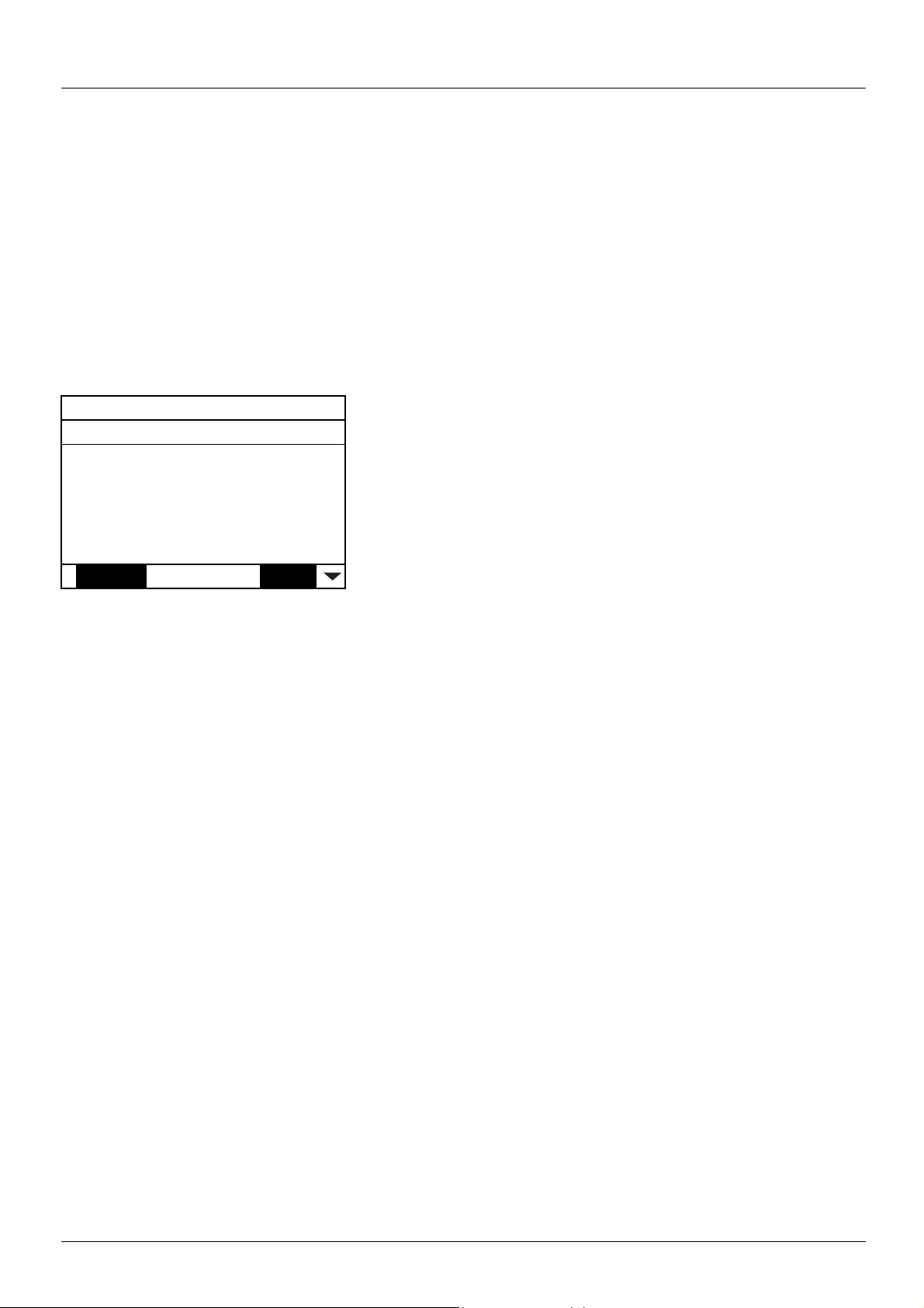
Configuring monitored parameters
It is possible to select up to 4 parameters to display their values in the [1.2 - MONITORING] menu on the graphic display terminal.
The selection is made via the [6 - MONITORING CONFIG.] menu ([6.3 - COM. MAP CONFIG.] submenu).
Each parameter in the range [Address 1 select] ... [Address 4 select] can be
used to select the parameter logic address. An address at zero is used to
disable the function.
In the example given here, the monitored words are:
• Parameter 1 = Motor current (LCR): logic address 3204, signed decimal
format.
• Parameter 2 = Motor torque (OTR): logic address 3205, signed decimal
format.
• Parameter 3 = Last fault occurred (LFT): logic address 7121,
hexadecimal format.
• Disabled parameter: 0; default format: Hexadecimal format
One of the three display formats below can be assigned to each monitored word:
Format Range Term i nal di sp lay
Hexadecimal 0000 ... FFFF [Hex]
Signed decimal -32 767 ... 32 767 [Signed]
Unsigned decimal 0 ... 65 535 [Unsigned]
RDY CAN +0.00Hz 0A
Address 1 select : 3204
FORMAT 1 : Signed
Address 2 select : 3205
FORMAT 2 : Signed
Address 3 select : 7121
Code Quick
FORMAT 3 : Hex
Address 4 select : 0
FORMAT 4 : Hex
6.3 COM. MAP CONFIG.
Note: If a monitored parameter:
- has been assigned to an unknown address
- has been assigned to a protected parameter
- has not been assigned
the value displayed in the [COMMUNICATION MAP] screen is: "-----" (see "Diagnostics" section).
14 1755865 11/2010

Configuration
Configuring communication fault management
The response of the drive in the event of a CANopen communication fault can be configured.
It can be configured via the graphic display termin al or the integrated display
terminal, from the [1.8 – FAULT MANAGEMENT] (FLt-) menu,
[COM. FAULT MANAGEMENT] (CLL-) submenu, via the
[CANopen fault mgt] (COL) parameter.
The values of the [CANopen fault mgt] (COL) parameter, which trigger a drive fault [CANopen com.] (COF), are:
Value Meaning
[Freewheel] (YES) Freewheel stop (factory setting).
[Ramp stop] (rMP) Stop on ramp.
[Fast stop] (FSt) Fast stop.
[DC injection] (dCI) DC injection stop.
The values of the [CANopen fault mgt] (COL) parameter, which do not trigger a drive fault, are:
Value Meaning
[Ignore] (nO) Fault ignored.
[Per STT] (Stt) Stop according to configuration of [Type of stop] (Stt).
[fallback spd] (LFF)
[Spd maint.] (rLS)
Change to fallback speed, maintained as long as the fault persists and the run command has not been
removed.
The drive maintains the speed at the time the fault occurred, as long as the fault persists and the run
command has not been removed.
RDY CAN +0.00Hz 0A
COM. FAULT MANAGEMENT
Network fault mgt : Freewheel
CANopen fault mgt : Freewheel
Modbus fault mgt : Freewheel
Code Quick
The fallback speed can be configured in the [1.8 – FAULT MANAGEMENT] (FLt-) menu using the [Fallback speed] (LFF) parameter.
1755865 11/2010 15

Diagnostics
LEDs
The two LEDs located on the right-hand side of the 7-segment integrated display
terminal indicate the CANopen communication status.
The two LEDs on the left-hand side are reserved for Modbus and are not described in
this manual.
LED LED state Altivar / CANopen state
The drive CANopen controller is in the "OFF" state.
The Altivar is in the CANopen "Stopped" state.
RUN
The Altivar is in the CANopen "Pre-operational" state.
The Altivar is in the CANopen "Operational" state.
No error signaled
Warning output by the Altivar CANopen controller
ERR
(e.g., too many error frames)
E
RROR due to the occurrence of a "Node Guarding" or "Heartbeat" event or an
"overrun" on the CANopen bus (network overload)
The CANopen controller is in the "OFF" state.
Key:
LED state Visual description of the LED state LED state Visual description of the LED state
The LED flashes at 2.5 Hz
The LED is on
The LED is in single flash mode
(on for 200 ms then off for
1 second)
The LED is in double flash mode
(on for 200 ms then off for
200 ms, on for 200 ms then off for 1 second)
(on for 200 ms then off for
200 ms)
The LED is off
16 1755865 11/2010

Diagnostics
Communication diagnostics
RUN CAN +50.00Hz 80A
COMMUNICATION MAP
Command Channel : CANopen
Cmd value : 000FHex
Active ref. channel : CANopen
Frequency ref. : 500.0Hz
Status word : 8627Hex
Code Quick
W3204 : 53
W3205 : 725
W7132 : 0000Hex
W0 : ----COM. SCANNER INPUT MAP
COM SCAN OUTPUT MAP
CMD. WORD IMAGE
FREQ. REF. WORD MAP
MODBUS NETWORK DIAG
MODBUS HMI DIAG
CANopen MAP
PROG. CARD SCANNER
On the display terminal, the [1.2 - MONITORING] (SUP-) menu ([COMMUNICATION MAP] (CMM-) submenu,
[CANopen MAP] submenu) can be used to display the communication status on CANopen.
LED display
• [RUN LED] LED ("OFF", "Stopped", "Pre-operational" or "Operational" state of the CANopen controller)
• [ERR LED] LED (CANopen error)
These LEDS are equivalent to the "CAN RUN" and "CAN ERR" LEDs on the 7-segment integrated terminal (where supplied together with
the drive).
The display on the screen opposite indicates that the CANopen controller is
in the "Operational" state ([RUN LED] LED permanently lit) and that the
controller has not detected any errors present ([ERR LED] not lit).
indicates an LED, which is not lit;
indicates an LED, which is lit.
RUN CAN +50.00Hz 80A
CANopen MAP
RUN LED :
ERR LED :
PDO1 IMAGE :
PDO2 IMAGE :
PDO3 IMAGE :
Code Quick
Canopen NMT state : Operational
Number of TX PDO : 2438
Number of RX PDO : 2438
Error code 0
RX Error Counter 0
TX Error Counter 0
1755865 11/2010 17

Diagnostics
In each of these screens and for each PDO transmitted or received, only the
[Transmit PDO•-•] or [Received PDO•-•] words actually transmitted and
received on the CANopen bus are displayed.
This means, for example, that for a recei ve PDO2 containing only 4 data bytes
(i.e., RP21 and RP22), the fields [Received PDO2-3] and [Received PDO2-4]
will not be displayed.
NMT chart display
The [CANopen NMT state] (NMTS) parame ter (logic add ress 6057, CANopen in dex/sub index 16#20 1E/3A) indicat es the NMT chart sta te.
The various possible values are [Boot], [Stopped], [Operational] and [Pre-Op] (Pre-operational).
PDO counter display
[Number of RX PDO] and [Number of TX PDO] indicate the number of PDOs received and the number of PDOs transmitted by the drive
(all PDO sets - PDO1, PDO2 and PDO3 - combined).
These counters are modulo 65 536 counters, i.e., the value is reset to zero once 65 535 is reached.
Last CANopen fault
The [Error code] (ErCO) parameter (index/subindex 16#201E/39) indicates the last active CANopen fault and maintains its value until the
last fault has disappeared.
The possible values are listed below:
Display Description
[0] No errors detected since the start of CANopen communication
[1] "Bus Off" requiring the drive to be restarted
[2] "Life Guarding" fault requiring a return to the NMT "Initialization" state
[3] "CAN overrun" error not requiring any specific action to be taken
[4] "Heartbeat" fault requiring a return to the NMT "Initialization" state
[5] NMT state chart fault (see section "CANopen NMT state chart")
Counters
The [RX Error Counter] (rEC1) parameter (logic address 6059, CANopen index/subindex 16#201E/3C) counts the number of frames
received with errors for all types of frame (PDO, SDO, etc.).
The [TX Error Counter] (tEC1) parameter (logic address 6058, CANopen index 16#201E/3B) counts the number of frames transmitted
with errors for all types of frame (PDO, SDO, etc.).
These types of error can be caused, for example, by network load problems or the short-circuiting of electrical signals on the bus.
The maximum count value supported by these two counters is 65 535.
PDO value display
A second level of submenus can be accessed via the [CANopen map] submenu: [PDO1 IMAGE], [PDO2 IMAGE] and
[PDO3 IMAGE].
Each of these submenus can be used to access a screen displaying the values transmitted and received by each set respectively (PDO1,
PDO2 and PDO3).
RUN CAN +50.00Hz 80A
PDO3 IMAGE
Received PDO3-1 : 1237
Received PDO3-2 : 50
Received PDO3-3 : 0
Received PDO3-4 : 304
Transmit PDO3-1 : 231
Code Quick
Transmit PDO3-2 : 642
Transmit PDO3-3 : 10
Transmit PDO3-4 : 9432
18 1755865 11/2010
Diagnostics
Control-signal diagnostics
On the terminal, the [1.2 - MONITORING] menu ([COMMUNICATION MAP] submenu) can be used to display control-signal diagnostic
information between the Altivar drive and the CANopen master:
• Active command channel
• Value of the control word (CMD) from the active command channel
• Active target channel
• Value of the target from the active target channel
• Value of the status word
• Values of the four param e te rs se l ec t ed by th e u se r
•The [COM. SCANNER INPUT MAP] submenu: is unnecessary for CANopen
•The [COM SCAN OUTPUT MAP] submenu: is unnecessary for CANopen
• In the [CMD. WORD IMAGE] submenu: control words from all channels
• In the [FREQ. REF. WORD MAP] submenu: frequency targets produced by all channels
Example of the display of communication diagnostic information
RUN CAN +50.00Hz 80A
COMMUNICATION MAP
Command Channel : CANopen
Cmd value : 000FHex
Active ref. channel : CANopen
Frequency ref. : 500.0Hz
Status word : 8627Hex
Code Quick
W3204 : 73
W3205 : 725
W7132 : 0000Hex
W0 : ----COM. SCANNER INPUT MAP
COM SCAN OUTPUT MAP
CMD. WORD IMAGE
FREQ. REF. WORD MAP
MODBUS NETWORK DIAG
MODBUS HMI DIAG
CANopen MAP
PROG. CARD SCANNER
Control word display
The [Command Channel] parameter indicates the active command channel.
The [Cmd value] parameter indicates the hexadecimal value of the control word (CMD) used to control the drive.
The [CMD. WORD IMAGE] submenu ([CANopen cmd.] parameter) is used to display the hexadecimal value of the control word sent by
CANopen.
1755865 11/2010 19
 Loading...