


THELIA SB 23
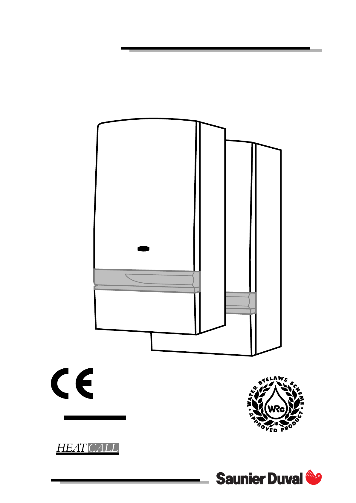
THELIA
THIS IS A CAT II2H3+ APPLIANCE
IN WARRANTY
TECHNICAL HELPLINE
01773 828400
01773 828100
1

INSTALLATION AND OPERATING INSTRUCTIONS
THELIA 23, THELIA 23 E, THELIA SB 23
Note!
The boiler serial number is marked on the label attached to the inside of the door. Refer to the
“Introduction” section page 3 for a description of the basic functions of the boiler. The “Users”
section describes how to safely operate the boiler.
USERS SECTION INSTALLATION SECTION
Introduction .................................................. Page 3
Commisioning ........................................................ 3
Controls & lighting ................................................. 4
Operation - Checks ............................................... 5
Clock - instructions for use ............................... 6 - 8
Draining................................................................... 9
Servicing/maintenance ........................................ 9
Introduction .................................................. Page 3
Technical data.............................................. 10 - 11
Dimensions ............................................................ 11
Boiler schematic ........................................... 12 - 13
Connection plate ................................................ 14
Piping system installation .................................... 15
Heating system design ........................................ 15
Hot water system design ..................................... 16
Boiler location ............................................... 16 - 17
Boiler installation .................................................. 18
Flue installation .............................................. 18 - 23
Electrical connection ................................... 24 - 25
Commissioning .............................................. 26 - 27
Operating safety devices ................................... 28
Settings ........................................................... 28 - 29
Changing gas type ............................................. 29
Mandatory warning notice for CEE countries
WARNING, this appliance was designed, approved and inspected to meet the requirements of the
English market. The identification plate located on the inside of the appliance certifies the origin
where the product was manufactured and the country for which it is intended.
If you see any exception to this rule, please contact your nearest Saunier Duval dealer.
Thank you in advance for you assistance.
2

INTRODUCTION
The Thelia 23 and Thelia 23E range of boilers are
wall mounted combination boilers providing central heating and instantaneous domestic hot water.
The Thelia SB23 boiler is a wall mounted boiler providing central heating only. This boiler can be used
in combination with a hot water tank to supply
domestic hot water.
The boilers are of the II2H3+ Gas Category for use
with natural gas (G20) as distributed in the United
Kingdom or with butane or propane gas (G30/31).
These instructions should be carefully followed for
the safe and economical use of your boiler.
Once the pilot has been lit (Thelia 23 and Thelia
SB23 only) the boiler is automatic in operation.
The boilers have a fan assisted balanced flue
which both discharge the products of combustion
to and draws the combustion air from the outside
air.
The boiler is supplied for rear outlet flue connection.
Alternatively, the boiler is designed to allow the
flue system to be connected to the top of the
boiler, top outlet flue connection. Refer to the flue
fitting instructions.
The boilers can be installed on either an external
wall or on an adjacent inside wall, that is, the flue
system will pass directly to the rear or to either side
to the terminal fitted on the outside wall face.
Ancillary equipment
A range of accessories are available including, vertical flue coponents, bends ....
For further information contact your supplier.
Boilers burning LPG or similar gas MUST NOT be
fitted in basements or below ground level.
COMMISSIONING
Gas Safety (Installation and Use) Regulations
In your interests and that of gas safety, it is the law
that ALL gas appliances are installed and serviced
by a competent person in accordance with the
above regulations.
Gas leak or fault
If a gas leak or fault exists or is suspected, turn the
boiler off and consult the local gas undertaking or
your installation/servicing company.
Boiler controls
The control panel, located at the lower front of
the boiler casing allows the boiler to be started,
shut down, controlled and monitored during use,
see diagram 2 (Thelia 23 and Thelia 23E) or diagram 3 (Thelia SB23).
Flue
Do not obstruct the outside terminal of the boiler.
Note. At stand-by, the boiler fan will run at low
speed, this is quite normal.
Starting the boiler
Before starting the boiler check that:
- The gas meter tap is open. If using butane or propane, check that valve on storage cylinder or tank
is open.
- The boiler gas service cock is open.
- The boiler is connected to the electrical supply
and switched on.
- The selector lever is in the left hand position.
3

CONTROLS AND LIGHTING
Lighting the THELIA 23 and THELIA SB 23 boilers
1 - Push in and hold
1 / ON
3 - Wait for
20 seconds
+
Note : On pressing the ‘ON’ button, the fan will be heard
to run at full speed after which the ignition sequence will
start and the pilot will light.
Should the pilot fail to remain alight or go out for any
reason, intentionally or unintentionally, always wait at
least 3 minutes before trying to relight.
2 - The pilot lights.
Check that pilot
is alight by looking through the
viewing window.
4 - Release : the
pilot must remain
ON, if the pilot
does not remain
lit, repeat the
previous steps.
1 / ON
Lighting the THELIA 23 E boiler
Push in and release
Diagram. 1
OPENING THE CONTROL PANEL COVER
Hab 129
The control panel, located at the lower front of the
boiler casing diag. 1 allows the boiler to be started,
shut down, controlled and monitored during use.
Control panel description (diag. 2 and 3) :
1-"ON" push - button.
2-"OFF" push - button.
4-Boiler thermostat.
5-Temperature gauge.
6-Pressure gauge.
7-Summer - Winter lever (THELIA 23, THELIA 23 E).
Summer - Winter switch (THELIA SB 23).
30 - Domestic hot water temperature
adjustment.
Diagram. 2
Diagram. 3
1 / ON
6
Hab 130
BOILER CONTROL PANEL THELIA 23, THELIA 23 E
5
4
3
2
1
0
bar
7
70
50
90
30
110
30
BOILER CONTROL PANEL THELIA SB 23
6
7
5
4
4
2
2
1
0 / OFF
1 / ON
1
Hab 043a
0 / OFF
4
3
2
1
0
bar
70
50
90
30
110
1 / ON
Hab 044a
4
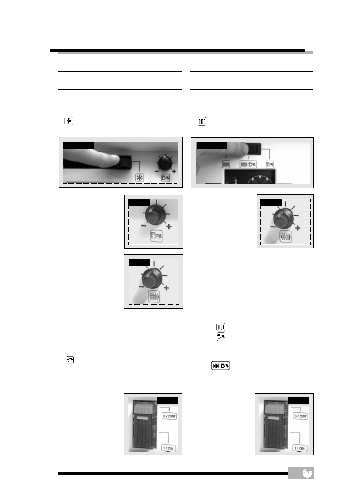
OPERATION - CHECKS
THELIA 23, THELIA 23 E
HEATING + HOT WATER
● Place the selector lever (diagram. 4)
to position (winter). In this position the domestic
hot water will have PRIORITY.
Diagram. 4
Hab 128
● Hot water : Turn the
knob (diagram. 5) in order to obtain a water
temperature suited to
the demand.
Diag. 5
Reg 012
THELIA SB 23
HEATING ONLY
● Turn the selector switch (diagram. 8)
to position (winter).
Diagram. 8
Hab 131
● Heating : turn the knob
(diagram. 9) in order to
obtain a water temperature suited to the demand, and adjust the
room thermostat to the
desired temperature.
Diag. 9
Reg 012
● Heating : turn the knob
(diagram. 6) in order to
obtain a water temperature suited to the demand, and adjust the
room thermostat to the
desired temperature.
Note : If you are out for a few days, set the button
(diagram. 6) to the minimum value in order to
protect the boiler from frost. In case of prolonged
absence, refer to “Draining” section page 9.
HOT WATER ONLY
● Place the selector lever (diagram. 4)
to position (summer).
Heating is switched OFF. The boiler will provide hot
water only. Turn the knob (diagram. 5) in order to
obtain a water temperature suited to the
demand.
STOPPING THE BOILER
● Press the (O/OFF)
push-button (diagram. 7) : this will clo-
se OFF the gas supply
valve. Electrical power
supply to the boiler will
be automatically switched OFF.
Diag. 6
Reg 012
Diag. 7
➞
Hab 133
Note : If you are out for a few days, set the button
(diagram. 9) to the minimum value in order to
protect the boiler from frost. In case of prolonged
absence, refer to “Draining” section page 9.
ALTERNATIVE OPERATING MODE THELIA SB 23
You may select the operating mode using the
switch (diagram. 8) :
Winter Heating only
Summer Domestic hot water only mode.
The boiler will keep the separate
storage cylinder, where fitted, at
the desired temperature.
Winter Heating and domestic hot water
mode
STOPPING THE BOILER
● Press the (O/OFF)
push-button (diagram. 10) : this will clo-
se OFF the gas supply
valve. Electrical power
supply to the boiler will
be automatically switched OFF.
Diag. 10
➞
Hab 133
5

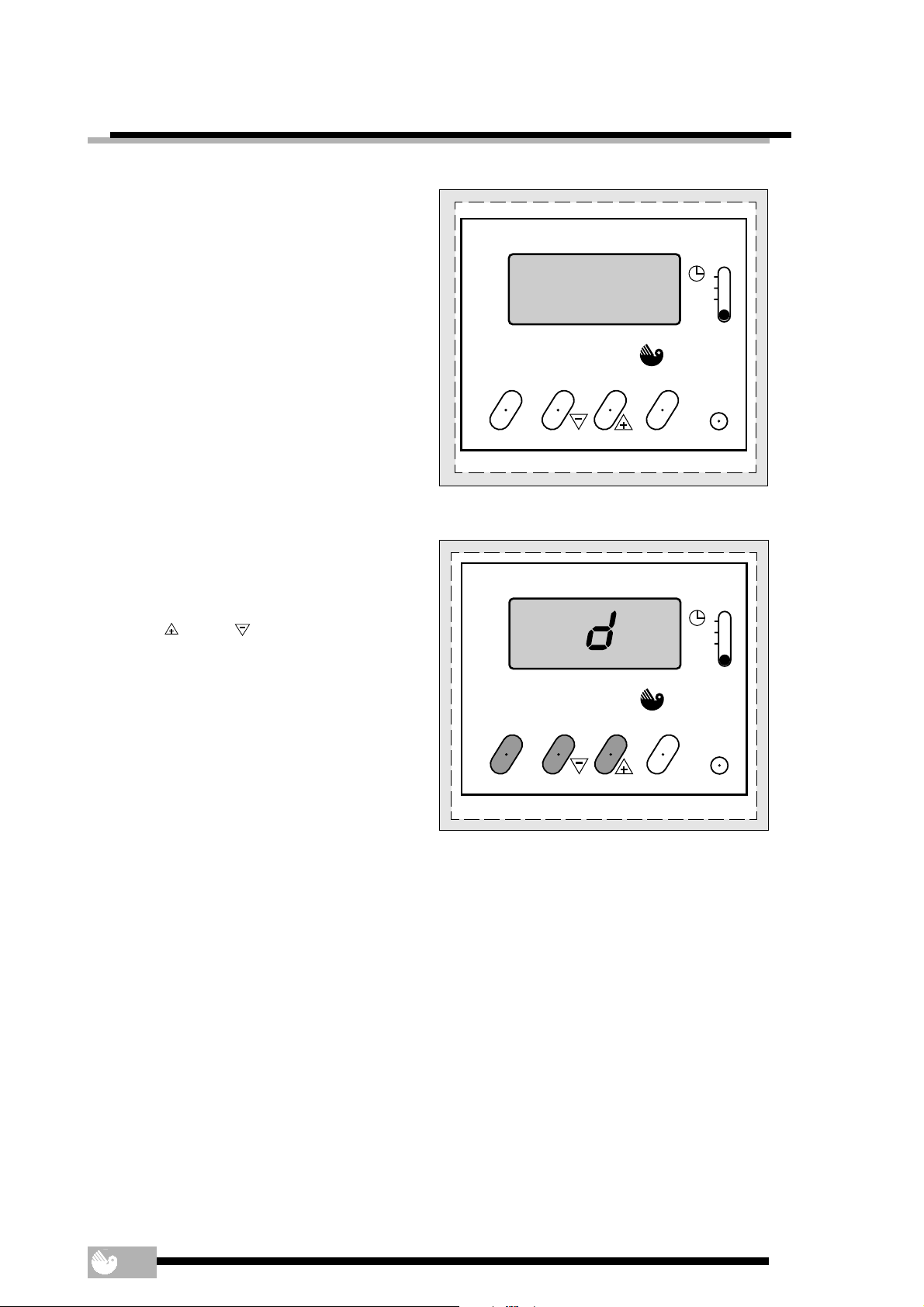
CLOCK - INSTRUCTIONS FOR USE
The boiler is connected to the electrical supply
and switched on.
IF FITTED, SET THE CLOCK TO WORK, AS THE
INSTRUCTIONS BELOW.
General Description
The timeclock has an internal, factory set
programme which switches the boiler "On" and
"Off" three times a day as below.
1st ON 06.30
1st OFF 08.30
2nd ON 12.00
2nd OFF 12.00
3rd ON 16.30
3rd OFF 22.30
It also has an advance feature, a hold or holiday
feature, details on how to set these are given
further on in these instructions.
Setting the Time
With the electrical supply to the boiler switched on,
place the slide switch to " ".
Press the "Reset" (res) button for a few seconds, using
a pointed object, such as a pencil. When released
the display will begin to flash, see diagram 11.
Using the "
the correct time in twenty four hour format, for
example, 1300 for 1pm, see diagram 12.
Helpful Hint
The "
times. Press and release for small changes. If you
press and hold down the time will "run".
"and " " buttons, set the display to
" and " " buttons are used to change
12.00
Saunier Duval
on
off enter
Diagram. 11
13.00
Saunier Duval
on
off enter
C1
AUTO
TIMER
C1
AUTO
TIMER
res
res
To Set the Programme "On" and "Off" Times
At this stage, if you want to use the internal, factory
set, programmes simply place the slide switch to
"Auto". The display will show the current time. The
"On" or "Off" symbol will be shown according to the
time of day.
To Override or Advance the Timeclock
To advance the time clock operation, that is,
switch the heating "On" when it is "Off" or the other
way round, press the "On/Off" button. The timeclock
will switch the heating "On" or "Off" as desired and
the "On" or "Off" symbol will flash to show that it has
been overridden. See diagram 13.
Note. The boiler will stay "On" or "Off", as selected,
until the timeclock programme reaches its next
"On" or "Off" time. From then on, the timeclock will
switch the boiler "On" and "Off" according to the
internal programme. When the boiler is again
controlled by the internal programme the "On" or
"Off" symbol will stop flashing. The timeclock
operation can be overridden in this way at any
time.
6
Diagram. 12
Saunier Duval
on
off enter
Diagram. 13
7.50
ON
C1
AUTO
TIMER
res

CLOCK - INSTRUCTIONS FOR USE
To Set Your Own Programme "On" and "Off" Times
Note. The timeclock can be set to give a minimum
of one and a maximum of three "On" and "Off"
times.
Place the slide switch to "C1". Press the "Enter"
button. The display will show the first "On" time, see
diagram 14.
Using the "
"On" time to the time you require. Press the "Enter"
button twice. This stores the new time and shows
it to confirm it has been stored in the timeclock
memory.
Press the "Enter" button again. The display will
show the first "Off" time, see diagram 15.
Using the " " and " " button, change the first
"Off" time to the time you require. Press the "Enter"
button twice. The display will show the first "On"
time. Press the "Enter" button again. The display
will now show the first "Off" time you have just
entered.
" and " " buttons, change the first
Diagram. 14
6.30
Saunier Duval
on
off enter
ON
C1
AUTO
TIMER
res
Repeat the above for the remaining "On" and "Off"
times.
When you have set the "On" and "Off" times you
require, place the slide switch to "Auto".
Note. If you do not want to set all three "On" and
"Off" times, follow the above instructions, but, after
you have set the times you require, set the other
times to show a series of dashes, using the "
" button, see diagram 16.
"
The series of dashes are between times 23.59 and
0.00.
Helpful Hint.
If you get confused and wish to start again, press
the "Reset" (res) button and the timeclock will go
back to the internal factory set programme. You
can now reset the current time and start again.
" and
Saunier Duval
on
off enter
Diagram. 15
8.30
-.--
OFF
ON
C1
AUTO
TIMER
C1
AUTO
TIMER
res
Saunier Duval
on
off enter
Diagram. 16
res
7
CLOCK - INSTRUCTIONS FOR USE
To Check the Programme "On" and "Off" Times
The programmed "On" and "Off" times can be
checked at any time by moving the slide switch
from "Auto" to "C1".
Successive presses of the "Enter" button will then
show the "On" and "Off" times.
Always return the slide switch to "Auto" to return to
normal timed working.
- H
Saunier Duval
OFF
C1
AUTO
TIMER
To Set the "Hold" or "Holiday" Feature
The timeclock has a "Hold" or "Holiday" feature
which can be set, if required, to keep the central
heating "On" or "Off" for a period between one
hour and twenty seven days. This can be used, for
example to keep the central heating "Off" during
a holiday. After the programmed time has gone
by, the boiler returns to its normal programmes.
To set the "Hold" or "Holiday" feature carry on as
follows:
Place the slide switch to "Timer", the letter "h" will
appear on the display, see diagram 17.
Using the "
time required.
After a hold period of twenty three hours has been
exceeded, the "h" symbol on the display will change
to a "d". The "hold" time will now be in days, instead
of hours, see diagram 18.
Use the "On/Off" button to set the boiler to the
required operation during the "Hold" period.
Place the slide switch to "Auto". After the
programmed hold time, the boiler will return to
normal timed working.
" and " " buttons, set the “Hold”
on
off enter
Diagram. 17
Saunier Duval
on
off enter
Diagram. 18
13
OFF
C1
AUTO
TIMER
res
res
8

DRAINING
Protection against freezing
If the boiler is to be out of use for any long periods
during severe weather conditions, it is recommended that the whole system, including the
boiler, be drained to avoid the risk of freezing.
If in doubt, consult your servicing company.
Draining and filling
Caution : the boiler is installed as part of a sealed
system which must only be drained and filled by a
competent person.
Note : If there is persistent loss of system pressure,
indicated by the pressure gauge, you must contact the installer or servicing company.
Safety valve
CAUTION. A safety valve with a discharge pipe is
fitted to this boiler.
The valve MUST NOT BE TOUCHED except by a
competent person. If the valve discharges at any
time, switch the boiler off and isolate it from the
electrical supply. Contact your installation/servicing company.
SERVICING/MAINTENANCE
To ensure the continued efficient and safe
operation of the boiler it is recommended that it is
checked and serviced at regular intervals. The
frequency of servicing will depend upon the installation conditions and usage but, in general,
once a year should be enough
Cleaning
The boiler casing can be cleaned with a damp
cloth followed by a dry cloth to polish.
Do not use abrasive or solvent cleaners.
Boiler casing
CAUTION. Do not remove or adjust the casing in
any way, as incorrect fitting may result in faulty
operation. If in doubt contact your installation/
servicing company.
9

TECHNICAL DATA
THELIA SB 23
THELIA 23 E
THELIA 23
Heating useful output, adjustable from... (kW) 8,9 8,9 8,9
Efficiency (%) 82,3 82,3 82,3
Heating max. output temperature (°C) 87 87 87
Heating regulation adjustable by user between 30 and 87°C
Heating system expansion vessel, effective capacity (l) 6,5 6,5 6,5
System max. capacity at 75°C (l) 140 140 140
Safety valve, maximum service pressure (bar) 3 3 3
Products outlet (Ø) 60 60 60
Fresh air inlet (Ø) 100 100 100
Output in hot water mode, automatically variable from... (kW) 8,9 8,9 —
Max. hot water temperature (°C) 65 65 —
Operating threshold flow rate in sanitary hot water mode (l/min.) 3 3 —
Specific flow rate (for 30°C temperature rise) (l/min.) 11 11 —
Mini. supply pressure (bar) 0,3 0,3 —
Max. supply pressure (bar) 10 10 —
Electrical supply (V) 230 230 230
Amperage (A) 0,73 0,73 0,73
Max. power absorbed (W) 130 130 130
(BTU/H) 30,000 30,000 30,000
to... (kW) 23,3 23,3 23,3
(BTU/H) 80,000 80,000 80,000
(BTU/H) 30,000 30,000 —
to... (kW) 23,3 23,3 —
(BTU/H) 80,000 80,000 —
Ø Pilot injector (mm) 0,28 — 0,28
Ø Burner injector (mm) 1,20 1,20 1,20
Inlet pressure (mbar) 20 20 20
(G20)
Gas rate (maximum) (m3/h) 2,70 2,70 2,70
Natural Gas
Gas rate (minimum) (m3/h) 1,13 1,13 1,13
Ø Pilot injector (mm) 0,18 — 0,18
Ø Burner injector (mm) 0,73 0,73 0,73
Inlet pressure (mbar) 29 29 29
(G 30)
Butane
Gas rate (maximum) (kg/h) 2,01 2,01 2,01
Gas rate (minimum) (kg/h) 0,84 0,84 0,84
Ø Pilot injector (mm) 0,18 — 0,18
Ø Burner injector (mm) 0,73 0,73 0,73
Inlet pressure (mbar) 37 37 37
(G31)
Gas rate (maximum) (kg/h) 1,98 1,98 1,98
Propane
Gas rate (minimum) (kg/h) 0,83 0,83 0,83
Ø Pilot injector (mm) — — —
Ø Burner injector (mm) — 2,40 —
Inlet pressure (mbar) — 8 —
(G130)
Gas rate (maximum) (m3/h) — 3,88 —
Town gas
Gas rate (minimum) (m3/h) — 1,63 —
10
 Loading...