


2000225294A.04.04
Instructions for Use Installation and Servicing
To b e l e f t w i t h t h e u s e r
F24e
G.C. No. 47-920-45
HIGH EFFICIENCY
CONDENSING COMBINATION BOILER
F28e
G.C. No. 47-920-39
HIGH EFFICIENCY
CONDENSING COMBINATION BOILER
F28e SB
G.C. No. 41-920-37
HIGH EFFICIENCY
CONDENSING SYSTEM BOILER


 11915
11915
Saunier Duval, Nottingham Road, Belper, Derbyshire. DE56 1JT
www.saunier-duval.co.uk

Guarantee Registration
Thank you for installing a new Saunier Duval appliance in your home.
Saunier Duval appliances' are manufactured to the very highest standard so we are pleased to offer our customers' a Comprehensive Guarantee.
This product is guaranteed for 24 months from the date of installation or 30 months from the date of manufacture, whichever is the shorter, for parts. In addition this product is guaranteed for 12 months from the date of intallation or 18 months from the date of manufacture, whichever is the shorter, for labour.
The second year of the parts guarantee, from the beginning of the 13th month onwards after installation, is conditional upon the boiler having been serviced by a CORGI registered gas installer, in accordance
with the manufacturer's recommendations. We strongly recommend regular servicing of your gas appliance, but where the condition is not met, any chargeable spare parts or components issued within the applicable guarantee period still benefit from a 12 month warranty from the date of issue by the manufacturer.
We recommend you complete and return as soon as possible your guarantee registration return literature, supplied in the document envelope.
If your guarantee registration return literature is missing you can obtain a copy by telephoning
the Saunier Duval Customer Service number 0044(0)1773 525914.
RECORD YOUR SAUNIER DUVAL APPLIANCE DIRECT BY CALLING
0044 (0)870 240 3413
Customer service :
Saunier Duval GB Great Britain :
Tel. 00 44 (0)1773 525914
Fax. 00 44 (0)1773 828070
Saunier Duval,
Nottingham Road, Belper, Derbyshire. DE56 1JT
Saunier Duval IE IRELAND:
Tel. 00 353 (0)14191919
Fax. 00 353 (0)14584806
Hevac,
Muirfield Drive
Naas Road
Dublin 12
Technical Advice Line:
Tel. 00 44 (0)1773 828400
General and Sales enquiries:
Tel. 00 44 (0)870 606 4351
Fax. 00 44 (0)1773 820569
|
|
2 |
2000225294A |
||

Contents
The instructions consist of three parts, User, Installation and Servicing Instructions, which includes the Guarantee Registration Card. The instructions are an integral part of the appliance and must, to comply with the current issue of the Gas Safety (Installation and Use) Regulations, be handed to the user on completion of the installation.
CONTENTS DESCRIPTION SECTION PAGE No.
INTRODUCTION |
|
Important Information |
|
|
|
4 |
|
Manual Handling |
|
|
|
5 |
|
|
|
|
|
|
||
|
|
Appliance Introduction |
|
|
|
7 |
|
|
Appliance Safety Devices |
|
|
|
7 |
INSTRUCTIONS |
|
General Information |
|
|
|
8 |
FOR THE USER |
|
Maintenance and Servicing |
|
|
|
8 |
|
Operating the Boiler |
|
|
|
9 |
|
|
|
|
|
|
||
|
|
(F24e & F28e ONLY) Optional Programmer |
|
|
|
11 |
|
|
Technical Data |
|
1 |
|
13 |
|
|
Technical Information |
|
2 |
|
15 |
|
|
Heating System Design |
|
3 |
|
16 |
|
|
(F24e & F28e ONLY) Domestic Hot Water |
|
|
|
|
|
|
System Design |
|
4 |
|
17 |
|
|
Boiler Schematic |
|
5 |
|
18/19 |
INSTALLATION |
|
Boiler Location, Flue and Ventilation |
|
6 |
|
20 |
|
Installation Preparation and Appliance Fixing |
|
7 |
|
22 |
|
INSTRUCTIONS |
|
|
|
|||
|
Horizontal Top Flue Preparation and Fitting |
|
8 |
|
23 |
|
|
|
|
|
|||
|
|
Vertical Flue Preparation and Fitting |
|
8 |
|
26 |
|
|
Twin Flue Preparation and Fitting |
|
8 |
|
28 |
|
|
Gas/Water Connections |
|
9 |
|
32 |
|
|
Safety Discharge Valve and |
|
|
|
|
|
|
Condensate Connections |
|
10 |
|
35 |
|
|
Electrical Connections |
|
11 |
|
37 |
|
|
Commissioning |
|
12 |
|
39 |
|
|
Servicing |
|
13 |
|
41 |
SERVICING |
|
Fault Finding |
|
14 |
|
46 |
INSTRUCTIONS |
|
Wiring Diagram |
|
15 |
|
50/51 |
|
Replacement of Parts |
|
16 |
|
52 |
|
|
|
|
|
|||
|
|
Spare Parts |
|
17 |
|
63 |
|
|
|
|
|
|
|
3 |
2000225294A |
INTRODUCTION - Important Information
WARNINGS
Gas Leak or Fault
Turn off the gas emergency control valve immediately. Eliminate all sources of ignition, i.e.smoking, blowlamps, hot air guns etc. Do not operate electrical lights or switches either on or off. Open all doors and windows,ventilate the area.
Sheet Metal Parts
This boiler contains metal parts (components) and care should be taken when handling and cleaning, with particular regard to edges.
Sealed Components
Under no circumstances must the User interfere with or adjust sealed parts.
Gas Category
The boilers are of the I2H category for use with Natural Gas (G20) as distributed in the United Kingdom and Ireland and cannot be used on any other gas.
Gas Safety (Installation and Use) Regulations
In your own interests and that of safety, it is the Law that ALL gas appliances must be installed by a competent person only, in accordance with the current issue of the above regulations.
Testing and Certification
This boiler is tested and certificated for safety and performance. It is, therefore, important that no alteration is made to the boiler, without permission, in writing, from Saunier Duval.
Any alteration not approved by Saunier Duval, could invalidate the certification, boiler warranty and may also infringe the current issue of the statutory requirements.
Control of Substances Hazardous to Health
Under Section 6 of The Health and Safety at Work Act 1974, we are required to provide information on substances hazardous to health.
The adhesives and sealants used in this appliance are cured and give no known hazard in this state.
Insulation Pads / Ceramic Fibre
Thesecancauseirritationtoskin,eyes andtherespiratory tract.
If you have a history of skin complaint you may be susceptible to irritation. High dust levels are usual only if the material is broken.
Normal handling should not cause discomfort, but follow normal good hygiene and wash your hands before eating, drinking or going to the lavatory.
If you do suffer irritation to the eyes or severe irritation to the skin seek medical attention.
Mandatory WARNING for EEC countries
Thisapplianceisdesigned,approvedandinspectedtomeetthe requirements of the intended market. The data label indicates where the product was manufactured and the country for which it is intended.
CE Mark
This boiler meets the requirements of Statutory Instrument, No. 3083 The Boiler (Efficiency) Regulations, and therefore is deemed to meet the requirements of Directive 92/42/EEC on the efficiency requirements for new hot water boilers fired with liquid or gaseous fuels.
TypetestforpurposesofRegulation5certifiedby:Notifiedbody 0063.
Product/production certified by: Notified body 0086.
The CE mark on this appliance shows compliance with:
1.Directive90/396/EEContheapproximationofthelawsofthe Member States relating to appliances burning gaseous fuels.
2.Directive 73/23/EEC on the harmonisation of the Laws of the Member States relating to electrical equipment designed for use within certain voltage limits.
3.Directive 89/336/EEC on the approximation of the Laws of the Member States relating to electromagnetic compatibility.
Electrical Supply
The boiler must be earthed.
All system components shall be of an approved type and all wiring to current I.E.E. wiring regulations.
External wiring must be correctly earthed, polarised and in accordance with the relevant standards.
In GB this is BS 6891.
In IE this is the current edition of I.S.813 "Domestic Gas Installations".
The boiler must be connected to a permanent 230V ac, 50Hz supply.
Connectionofthewholeelectricalsystemoftheboiler,including any heating controls, to the electrical supply must be through one common isolator and must be fused 3 Amp maximum.
Isolation should be by a double pole switched fused spur box, with a minimum gap of 3mm for both poles. The fused spur box should be readily accessible and preferably adjacent to the appliance. It should be identified as to its use.
Alternatively connection can be made through an unswitched shuttered socket and 3A fused 3-pin plug both to the current issue of BS 1363 may be used, provided they are not used in a room containing a bath or shower.
Wiring to the boiler must be PVC 85OC insulated cable, not less than 0.75mm2 (24/0.20mm).
2000225294A |
4 |

Introduction - Manual Handling
IMPORTANT. WithregardstotheManualHandlingOperations, 1992Regulations,thefollowingliftoperationsarerecommended as the appliance weight exceeds a one man lift.
General recommendations when handling
Clear the route before attempting the lift.
Ensure safe lifting techniques are used - keep back straight - bend using legs.
Keep load as close to body as possible.
Do not twist - reposition feet instead.
If 2 persons performing lift, ensure co-ordinated movements during lift.
Avoid upper body/top heavy bending - do not lean forward/ sideways.
Recommend wear suitable cut resistant gloves with good grip to protect against sharp edges and ensure good grip.
Always use assistance if required.
Removal of carton from delivery van
Recommend 2 person lift or 1 person with use of sack truck. If 1 person is performing lift, straddle the load, tilt and place carton into position on truck. Recommend secure appliance onto truck with suitable straps. Ensure safe lifting techniques are used - keep back straight - bend using legs. Keep load as close to body as possible. If 2 persons performing lift, ensure co-ordinated movements during lift. Always use assistance if required.
Carriage of carton from point of delivery to point of installation - ground floor
Recommend 2 person lift or 1 person with use of sack truck. If 1 person is performing lift, straddle the load, tilt and place carton into position on truck. Recommend secure appliance onto truck with suitable straps. Ensure safe lifting techniques are used - keep back straight - bend using legs. Keep load as close to body as possible. If 2 persons performing lift, ensure co-ordinated movements during lift. Clear the route before attempting the lift. If removing boiler from truck straddle the load and tilt forwards to facilitate secure grip. Ensure safe lifting techniques are used - keep back straight - bend using legs. Do not twist - reposition feet instead. Take care to avoid trip hazards, slippery or wet surfaces and when climbing steps and stairs. Always use assistance if required.
Carriage of carton from point of delivery to point of installation - first or higher floor, cellar.
Recommend 2-person lift or 1 person with use of sack truck. If 1 person is performing lift, straddle the load, tilt and place carton into position on truck. Recommend secure appliance onto truck with suitable straps. Ensure safe lifting techniques are used - keep back straight - bend using legs. Keep load as close to body as possible. If 2 persons performing lift, ensure co-ordinated movementsduringlift.Avoidupperbody/topheavybending-do not lean forward/sideways. Clear the route before attempting the lift. If removing boiler from truck straddle the load and tilt forwards to facilitate secure grip. Ensure safe lifting techniques are used - keep back straight - bend using legs. Do not twist - reposition feet instead. Take care to avoid trip hazards, slippery or wet surfaces and when climbing steps and stairs. Always use assistance if required.
Carriage of carton from point of delivery to point of installation - roofspace.
Recommend 2-person lift. Ensure co-ordinated movements during lift. Avoid upper body/top heavy bending - do not lean forward/sideways. Clear the route before attempting the lift. Take care to avoid trip hazards, slippery or wet surfaces and when climbing steps and stairs. When transferring appliance into roofspace, recommend 1 person to be in roofspace to receive the appliance and other person to be below to pass up and support appliance. Ensure safe lifting techniques are used - keep back straight - bend using legs. Keep load as close to body as possible. Always use assistance if required. It is assumed safe access, flooring and adequate lighting are providedintheroofspace. Itisrecommendedariskassessment of the roof space area be carried out before moving the appliance into the area to take into account access, stability of flooring, lighting and other factors, and appropriate measures taken.
Unpacking of Appliance from carton.
Recommend 2 persons unpack appliance from carton. Always keep working area clear. Recommend cut base end of carton and open carton flaps, then tilt boiler forwards from its side onto its base and remove carton by sliding up over the boiler. Ensure safeliftingtechniquesareused-keepbackstraight-bendusing legs. Keep load as close to body as possible. Always use assistance if required. Dispose of packaging in a responsible manner. Recommend wear suitable cut resistant gloves with good grip to protect against sharp edges and ensure good grip when handling appliance outside packaging.
Positioning of Appliance for Final Installation - no obstructions.
Recommend 2 persons lift appliance to position into place. Fit bracket securely onto wall before lifting appliance into position. Obtain firm grip on front and sides of appliance, lift upwards, ensure stable balance achieved and lift upwards to position in place on bracket. Ensure safe lifting techniques are used - keep backstraight-bendusinglegs-whenliftingloadfromfloorlevel. Do not twist - reposition feet instead. Keep boiler as close as possible to body throughout lift to minimise strain on back. Ensure co-ordinated movements to ensure equal spread of weight of load. Always use assistance if required. Recommend wear suitable cut resistant gloves with good grip to protect against sharp edges and ensure good grip when handling appliance.
5 |
2000225294A |

Introduction - Manual Handling
Positioning of Appliance for Final Installation - above worktop, foreseeable obstructions etc.
Recommend 2 persons lift appliance to position into place. Fit bracket securely onto wall before lifting appliance into position. Obtain firm grip on front and sides of appliance, lift upwards, onto worktop if practicable. Ensure stable balance achieved and lift upwards to position in place on bracket. If 2 persons positioning onto bracket obtain firm grip at front and sides/base of boiler. Ensure co-ordinated movements during 2 person lifts to ensure equal spread of weight of load. Ensure safe lifting techniques are used - keep back straight - bend using legs - when lifting load from floor level. Do not twist - reposition feet instead. Keep boiler as close as possible to body throughout lift to minimise strain on back. Avoid upper body/top heavy bending-donotleanforward/sideways. Alwaysuseassistance if required. Recommend wear suitable cut resistant gloves with good grip to protect against sharp edges and ensure good grip when handling appliance.
Positioning of Appliance for Final Installation - within compartment etc. restricting installation.
Recommend 2 persons lift appliance to position into place, space permitting. Fit bracket securely onto wall before lifting appliance into position. Obtain firm grip on front and sides of appliance, lift upwards, onto worktop if practicable. Ensure stable balance achieved and lift upwards to drop into place onto bracket. If 2 persons positioning onto bracket obtain firm grip at front and sides/base of boiler. Ensure co-ordinated movements during 2 person lifts to ensure equal spread of weight of load. If 1 person positioning onto bracket recommend obtain firm grip supporting base of boiler. Ensure safe lifting techniques are used - keep back straight - bend using legs - when lifting load from floor level. Do not twist - reposition feet instead. Keep boiler as close as possible to body throughout lift to minimise strain on back. Always use assistance if required. Recommend wear suitable cut resistant gloves with good grip to protect against sharp edges and ensure good grip when handling appliance.
Positioning of Appliance for Final Installation - in roof space restricting installation.
Recommend 2 persons lift appliance to position into place, space permitting. Fit bracket securely onto wall before lifting appliance into position. Obtain firm grip on front and sides of appliance, lift upwards, ensure stable balance achieved and lift upwardstodropintoplaceontobracket. If2personspositioning onto bracket obtain firm grip at front and sides/base of boiler. Ensure co-ordinated movements during 2 person lifts to ensure equal spread of weight of load. If 1 person positioning onto bracket recommend obtain firm grip supporting base of boiler. Ensure safe lifting techniques are used - keep back straight - bend using legs - when lifting load from floor level. Do not twist - reposition feet instead. Keep boiler as close as possible to body throughout lift to minimise strain on back. Always use assistance if required. Recommend wear suitable cut resistant gloveswithgoodgriptoprotectagainstsharpedgesandensure good grip when handling appliance. It is recommended a risk assessment of the roof space area be carried out before moving the appliance into the area to take into account access, stability of flooring, lighting and other factors, and appropriate measures taken.
2000225294A |
6 |

User Instructions - Appliance Introduction
The EnviroPlus F24e & F28e boilers are wall mounted high efficiencycondensingcombinationboilerswithelectronicignition providing central heating and instantaneous hot water.
The EnviroPlus F28e SB boiler is a wall mounted high efficiency condensing system boiler with electronic ignition providing central heating and indirect hot water.
Both the central heating and domestic hot water (F24e & F28e only) temperature are user adjustable.
F24e & F28e ONLY Domestic hot water demand always has priority over heating demand.
The boiler is designed for use as part of a sealed water central heating system with fully pumped circulation. The pump, expansion vessel and associated safety devices are all fitted within the boiler.
The boilers have fan assisted balanced flues which both discharges the products of combustion to and draws the combustion air from the outside of the room.
The boilers are suitable for horizontal top, vertical flue or twin-pipe flue system connection. Refer to section 8 of these instructions and the Saunier Duval flue options guide (available from your nearest stockist) for further information.
Manufacturer's instructions must not be taken as overriding statutoryrequirements.ReferenceintheseinstructionstoBritish standards and statutory regulations/requirements apply only to the United Kingdom. For Ireland the current edition of I.S.813 "Domestic Gas Installations" must be used.
These instructions should be carefully followed for the safe and economical use of your boiler.
Note: The boiler serial number is marked on the data label attached to the inner casing panel. The 'Controls & lighting' section describes how to safely use the boiler.
Accessories
A range of accessories are available.
For further information contact your supplier.
User Instructions - Appliance Safety Devices
Overheating safety
In the event of the boiler overheating the safety devices will cause a safety shutdown. If this happens, call your installation/ servicing company.
Electrical supply failure
The boiler will not operate without an electrical supply. Normal operation of the boiler should resume when the electrical supply is restored.
Reset any central heating system controls, to resume normal operation.
If the boiler does not resume normal operation turn the mains reset switch off and on. If the boiler does not resume normal operation call your installation/servicing company.
Heating safety valve
CAUTION: A Safety Valve with a discharge pipe is fitted to this boiler.
The valve MUST NOT BE TOUCHED except by a competent person. If the valve discharges at any time, switch the boiler off andisolateitfromtheelectricalsupply.Contactyourinstallation/ service company.
Frost protection
The appliance has a built in frost protection device that protects the boiler from freezing. With the gas and electric supplies ON and irrespective of any room thermostat setting, the frost protection device will operate the pump when the temperature of the boiler water falls below 7OC.
The burner will fire if the temperature inside the boiler falls to 3OC.
When the temperature reaches 10OC the boiler stops.
Any other exposed areas of the system should be protected by a separate frost thermostat.
7 |
2000225294A |

User Instructions - General Information
IMPORTANT NOTE:
Please be advised that the 'Benchmark' logbook should be completed by the engineer on completion of commissioning or servicing.
All CORGI Registered Installers carry a CORGI ID card, and have a registration number. Both should be recorded in your benchmark Logbook. You can check your installer is CORGI registered by calling CORGI direct on: 01256 372300.
Water Treatment
In the case of an existing installation, it is ESSENTIAL that prior to installing the new boiler the system is thoroughly flushed.
For optimum performance after installation of a new system, the boiler and its associated central heating system should also be flushed. Flushing should be carried out in accordance with BS7593: 1992 using a cleanser such as Sentinel X300 or X400, Fernox Superfloc or Salamander corrosion guard cleaner.
For long-term corrosion protection, after flushing, an inhibitor suitable for stainless steel exchangers should be used, refer to the current issue of BS 5449 and BS 7593 on the use of inhibitors in central heating systems. Examples are Sentinel X100 Fernox or Salamander corrosion guard inhibitor.
Compartment Installations
If the boiler is fitted into a compartment it does not require ventilation openings.
Do not use the compartment for storage.
The boiler is not suitable for cupboard installation.
Clearances
If fixtures are positioned close to the boiler, space must be left as shown in section 2. Enough space must also be left in front of the boiler to allow for servicing.
Condensate Drain
The condensate drain, see section 10.2, must not be modified or blocked.
Pluming from flue terminal
Like all condensing boilers this appliance will produce a plume of condensation from the flue terminal in cool weather. This is due to the high efficiency and hence low flue gas temperature of the boiler. It is normal and not a fault indication.
Electrical and Gas Supplies
If the mains electricity and gas are to be turned off for any long periods during severe weather, it is recommended that the whole system, including the boiler, should be drained to avoid the risk of freezing. Make sure that, if fitted, the immersion heater in the cylinder is switched off.
If you have a sealed water system contact your installation/ servicing company as draining, refilling and pressurising MUST be carried out by a competent person.
User Instructions - Maintenance and Servicing
Draining and filling
Caution: The boiler is installed as part of a sealed system which must only be drained and filled by a competent person.
If the boiler is to be out of use for any long periods during severe weather conditions, it is recommended that the whole system, including the boiler, be drained to avoid the risk of freezing.
If in doubt, consult your installation/servicing company.
Cleaning
WARNING: This appliance contains metal parts (components) and care should be taken when handling and cleaning with particular regard to edges of sheet metal parts to avoid any possibility of personal injury.
The boiler casing can be cleaned using a mild liquid detergent with a damp cloth, then a dry cloth to polish.
Do not use any form of abrasive or solvent cleaner as you may damage the paintwork.
Do not use abrasive or solvent cleaners.
Maintenance and Servicing
To ensure the continued efficient and safe operation of the appliance it is recommended that it is checked and serviced as necessary at regular intervals. The frequency of servicing will depend upon the particular installation conditions and usage, refertoguaranteeregistrationonthefrontcoverofthisliterature.
If this appliance is installed in a rented property there is a duty of care imposed on the owner of the property by the current issue of the Gas Safety (Installation and Use) Regulations, Section 35.
Servicing/maintenance should be carried out by a competent person in accordance with the rules in force in the countries of destination.
To obtain service, please call your installer or Saunier Duval service organisation using the telephone number on the front cover of this literature.
Spare Parts
REMEMBER, When replacing a part on this appliance, use only spare parts that you can be assured conform to the safety and performance specification that we require. Do not use reconditionedorcopypartsthathavenotbeenclearlyauthorised by Saunier Duval.
If a part is required contact Saunier Duval Service using the telephone number on the inside front cover of this booklet.
Please quote the name of the appliance, this infomation will be on the name badge on the front of the appliance.
If in doubt seek advice from the local gas company or Saunier Duval service organisation using the telephone number on the inside front cover of this booklet.
2000225294A |
8 |
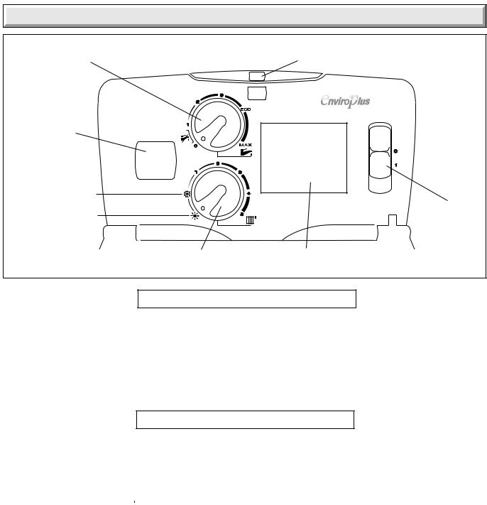
User Instructions - Operating the Boiler
Domestic hot water temperature control knob
(F24e & F28e ONLY)
Digital Display
HEATING "ON" HEATING "OFF"
Running lamp illuminated green when burner is lit |
12170 |
|
(fault indicated by a red flashing light) |
||
|
ON/OFF switch
Central heating |
Optional Programmer |
|
control knob |
(F24e & F28e ONLY) |
Diagram 1 |
OPERATION OF THE BOILER
1.Check that all isolating valves on the boiler are open and that water flows from the hot water tap.
2.If you are in any doubt about the boiler being filled with water contact your installer or Saunier Duval's own service organisation using the telephone number on the inside front cover of this booklet.
3.Check that the electrical supply to the boiler is ON and set any remote controls as required.
4.With the User controls in their "OFF" positions, as shown in the above diagram, turn the ON/OFF switch to the ON (1) position, the running lamp will initially illuminate (green) then go off, the system pressure will be displayed and should read on the digital display, at least 0.7bar (recommended 1.0bar), if less, pressurise as described in the System Pressurisation section.
USER CONTROLS
CENTRAL HEATING CONTROL
1.Turn the central heating knob "ON", the lighting sequence will begin, the running lamp will illuminate (green) to indicate the boiler has lit, the system temperature will now be displayed instead of system pressure.
The temperature of the central heating water can be adjusted by turning the central heating control knob to desired setting between 1 'Min' and 5 'Max' or  frost protection. 5 'Max', is appoximately 87°C. Set the control knob to
 to switch off heating.
If the boiler fails to light, reset the controls, see paragraph below, TO RESET
If a fault occurs the running lamp will flash red and a fault code will appear on the digital display.
DOMESTIC HOT WATER CONTROL (F24e & F28e ONLY)
2.Position 0 - hot water OFF. Position 1 - hot water between 38oC and 55oC approx.
The ECO setting is recommended and ideally suited to normal family use (showers, washing up etc.). Positions between ECO and MAX are for occasional use, for water above 55oC approx.
TO RESET
3.Turn the ON/OFF switch to 0, wait for 5 seconds, turn ON/OFF switch to 1, the boiler is reset.
If the fault persists contact your installer/service provider using the telephone number on the inside font cover of this booklet.
TO TURN THE BOILER OFF
4.Turn the ON/OFF switch to the OFF (0) position.
Turn the gas supply OFF at the gas service cock if the boiler is to be out of use for some time.
9 |
2000225294A |

User Instructions - Operating the Boiler
System Pressurisation
(F24e & F28e ONLY) If the digital display shows pressure less than 0.7bar, re-pressurise the system to 1bar by gently opening thebuiltinfillingtapsunderneaththeboiler,seediagram 2. Tap extension tools are provided to facilitate this.
Using the tap extensions connected to tap (a) and tap (b) open tap (b) and then slowly open tap (a). Re-pressurise the system to a pressure of 1.0 bar indicated on the digital display. When the system is pressurised you must close tap (b) and then tap
(a).
Ifthesystemrepeatedlylosespressure,YOUMUSTCONTACT YOUR INSTALLER OR SAUNIER DUVAL'S OWN SERVICE ORGANISATION USING THE TELEPHONE NUMBER ON THE INSIDE FRONT COVER OF THIS BOOKLET.
(F28e SB ONLY) This sealed water system must be filled and pressurised by a competent person.
YOU MUST CONTACT YOUR INSTALLER OR SAUNIER DUVAL'S OWN SERVICE ORGANISATION USING THE TELEPHONE NUMBER ON THE INSIDE FRONT COVER OF THIS BOOKLET.
To Turn the Boiler Off
There is a mains reset switch on the right hand side of the controls fascia, which will isolate the boiler. However, it is preferable to leave the electrical supply on whenever possible to permit operation of the built-in frost protection and daily pump and valve exercise.
To turn off the central heating use the room thermostat or programmer.
Toturnoffthedomestichotwaterturnthehotwatertemperature control knob to the minimum setting.
For holiday mode turn both of the temperature knobs to the minimum setting.
12211 |
|
FILLING LOOP |
|
|
TAP (b) |
TAP (a) |
EXTENSION |
|
|
EXTENSION |
|
(F24e & F28e ONLY) |
Diagram 2 |
2000225294A |
10 |
User Instructions - (F24e & F28e ONLY) Optional Programmer
General description
The programmer is factory preset which switches the boiler on and off up to three times a day as shown below.
FACTORY PRESET TIMES
1st ON 6.30 1st OFF 8.30 2nd ON 12.00 2nd OFF 12.00 3rd ON 16.30 3rd OFF 22.30
NOTE: The 2nd "ON" and "OFF" preset time will not bring the boiler on. In most cases this may not be required but can be programmed by the user if desired.
The programmer has an "advance" feature to manually switch the boiler "ON" or "OFF" and a holiday feature so that you can programme the boiler to start automatically when returning from holiday. Details on how to set these feature are given further on in these instructions.
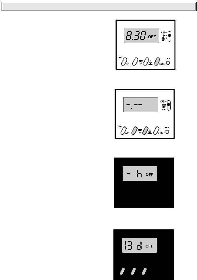
Setting the Time
Make sure there is an electrical supply to the boiler and the boiler is switched "ON".
Place the slide switch to 
Press the "RESET" (res) button for a few seconds, using a pointed object such as a pencil. When released the display will begin to flash, see diagram 2. Using the + and - buttons, set the display to the correct time in twenty four hour format, for example, 1300 for 1pm, see diagram 3.
Helpful hint The + and - buttons are used to change the times. Press and release for small changes, hold the button down and the time will change quickly.
To use the internal, factory set, programmes place the slide switch to the 'RUN' position. The display will show the current time and the "ON" or "OFF" symbol will be displayed according to whether the programmer has switched the boiler on or off.
To Override or Advance the programmer
To advance the time clock operation, that is, switch the heating on when it is off or vice versa, press the "ON/OFF" button. The programmer will switch the heating on or off and the "ON" or "OFF" symbol will flash on the display to show that it has been
overridden, see diagram 4.
Note: The boiler will stay "ON" or "OFF", as selected, until the programmer reaches its next on or off time. From then on, the programmer will switch the boiler on and off according to the internal programme.
When the boiler is again controlled by the internal programme the "ON" or "OFF" symbol will stop flashing. The operation of
the programmer can be overridden in this way at any time.
10205
Diagram 2
10302
Diagram 3
10303
Diagram 4
10304
Diagram 5
11 |
2000225294A |
User Instructions - (F24e & F28e ONLY) Optional Programmer
To set the programmer ON and OFF times
Note: The programmer can be set to give a minimum of one and a maximum of three "ON" and "OFF" times.
Place the slide switch to "SET".
Press the "enter" button. The display will show the first "ON" time, see diagram 5.
Using the + and - buttons, change the first "ON" time to the time you require then press the "enter" button twice. This stores the new time and displays it to confirm it has been stored in the programmer memory.
Press the "enter" button again. The display will show the first "OFF" time, see diagram 6.
Using the + and - buttons, change the first "OFF" time to the time you require. Press the "enter" button twice. The display will show the first "ON" time.
Press the "enter" button again. The display will now show the first "OFF" time you have just entered.
Repeat the above for the remaining "ON" and "OFF" times.
When the "ON" and "OFF" times have been set, place the slide switch to "RUN".
Note: If all three "ON" and "OFF" times are not required, follow the above instructions but after setting the desired times, set the other times to show a series of dashes, using the + and - buttons, see diagram 7. The series of dashes are between times 23.59 and 0.00.
Helpful Hint If you get confused and wish to start again, press the "Reset" (res) button and the programmer will revert to the internal factory set programme. You can now reset the current time and start again.
To check the programme "ON" and "OFF" times
The programmed "ON" and "OFF" times can be checked at any time by moving the slide switch from "RUN" to "SET".
Successive presses of the "enter" button will show the "ON" and "OFF" times.
Alwaysreturntheslideswitchto"RUN"toreturntonormaltimed working.
To set the 'Holiday' feature
The programmer has a holiday feature which can be set, if required, to keep the central heating "OFF" for aperiod between onehourandtwentysevendays.Thiscanbeused,forexample, to keep the central heating "OFF" during a holiday. After the programmedtimehaselapsed,theboilerwillreturntoitsnormal programmes and switch on the boiler in time for a return from holiday.
Place the slide switch to " HOL " , the letter "h" will appear on the display, see diagram 8.
Using the + and - buttons, set the "Holiday" time required.
Afterthedisplayhasshown"twentythreehours",the"h"symbol on the display will change to a "d". The Holiday time will now be displayed in days, instead of hours, see diagram 9.
Use the "ON/OFF" button to set the boiler to the required operation during the "Holiday" period.
Place the slide switch to "RUN".
After the programmed "Holiday" time, the boiler will return to normal timed operation.
ON
10305
Diagram 6
10306
Diagram 7
10307
Diagram 8
10308
Diagram 9
2000225294A |
12 |

1 Technical Data
12179
Net lift weight (boiler only)
(F24e 47 kg) (F28e 47 kg) (F28e SB 42 kg)
Gross lift weight (boiler and packaging) (F24e 52 kg) (F28e 52 kg) (F28e SB 47 kg)
The boiler and fittings pack are delivered in one carton. The flue is supplied separately.
FLOW |
D.H.W.OUT |
GAS |
D.C.W.IN |
RETURN |
Diagram 1.1
13 |
2000225294A |

1 Technical Data
(F24e ONLY) Heating
Heat input (max) NET Q |
|
25.6 kW |
|
|
87,347 BTU/H |
Heat input (min) NET Q |
|
5.0 kW |
|
|
17,060 BTU/H |
Heat output (max) GROSS P |
|
25.1 kW |
|
|
85,641 BTU/H |
Heat output (min) GROSS P |
|
4.9 kW |
|
|
16,719 BTU/H |
Heat output (max) Condensing Mode |
26.5 kW |
|
|
|
90,418 BTU/H |
Efficiency - Sedbuk A |
|
90.3% |
Maximum heating temperature |
87° C |
|
Expansion vessel effective capacity |
8 l |
|
Expansion vessel charge pressure |
0.5 bar |
|
Maximum system capacity at 75°C |
110 l |
|
Safety valve, |
maximum service pressure 3 bar |
|
(F28e ONLY) Heating
Heat input (max) NET Q |
|
29.6 kW |
|
|
|
100,995 |
BTU/H |
Heat input (min) NET Q |
|
5.9 kW |
|
|
|
20,130 |
BTU/H |
Heat output (max) GROSS P |
|
29.0 kW |
|
|
|
98,948 |
BTU/H |
Heat output (min) GROSS P |
|
5.8 kW |
|
|
|
19,789 |
BTU/H |
Heat output (max) Condensing Mode |
31.2 kW |
||
|
|
106,454 |
BTU/H |
Efficiency - Sedbuk A |
|
|
90.3% |
Maximum heating temperature |
|
87° C |
|
Expansion vessel effective capacity |
|
8 l |
|
Expansion vessel charge pressure |
0.5 bar |
||
Maximum system capacity at 75°C |
|
110 l |
|
Safety valve, |
maximum service pressure 3 bar |
||
(F24e ONLY) Hot water
Heat input (max) NET Q |
25.6 kW |
|
|
87,347 BTU/H |
|
Heat input (min) NET Q |
5.0 kW |
|
|
17,060 BTU/H |
|
Heat output (max) GROSS P |
25.1 kW |
|
|
85,641 BTU/H |
|
Heat output (min) GROSS P |
4.9 kW |
|
|
16,719 BTU/H |
|
Maximum hot water temperature |
63° C |
|
Minimum hot water temperature |
38° C |
|
Specific flow rate (for 35° C temp rise) |
10 l/min. |
|
Threshold flow rate |
1.5 l/min. |
|
Maximum supply pressure |
10 bar |
|
Minimum supply pressure |
1 bar |
|
(F28e ONLY) Hot water
Heat input (max) NET Q |
29.6 kW |
|
|
100,995 BTU/H |
|
Heat input (min) NET Q |
5.9 kW |
|
|
20,130 BTU/H |
|
Heat output (max) GROSS P |
29.0 kW |
|
|
98,948 BTU/H |
|
Heat output (min) GROSS P |
5.8 kW |
|
|
19,789 BTU/H |
|
Maximum hot water temperature |
63° C |
|
Minimum hot water temperature |
38° C |
|
Specific flow rate (for 35° C temp rise) |
12 l/min. |
|
Threshold flow rate |
1.5 l/min. |
|
Maximum supply pressure |
10 bar |
|
Minimum supply pressure |
1 bar |
|
Combustion
Products outlet diameter |
60 mm |
Fresh air inlet diameter |
100 mm |
Combustion products values |
CO (40ppm) |
at Max. |
CO2 (9.4%) |
|
NOx class 5 (3.5ppm) |
Electrical
Electrical supply |
230 V ~ 50Hz |
||
|
|
|
|
Electrical rating |
180 W fused at 3A |
||
|
|
|
|
Level of protection |
IPX4D |
||
|
|
|
|
Internal Fuse rating |
125mAT on PCB |
||
|
|
|
|
|
3.15AT on Fan Supply |
||
|
|
|
|
Natural Gas (G20)
Inlet pressure |
20 mbar |
|
|
|
|
CO2 |
on Max Open |
9.2% |
|
|
|
CO2 |
on Low Open |
8.3% |
|
|
|
Gas rate maximum |
3.1 m3/h |
|
|
|
|
Gas rate minimum |
0.6 m3/h |
|
|
|
|
2000225294A |
14 |

2 Technical Information
IMPORTANT NOTICE
Where no British Standards exists, materials and equipment should be fit for their purpose and of suitable quality and workmanship.
Theinstallationofthisboilermustbecarriedoutbyacompetent person in accordance the rules in force in the countries of destination.
Manufacturer's instructions must not be taken as overriding statutory requirements.
1.2 Statutory Requirements
In GB the installation of the boiler must be carried out by a competent person as described in the following regulations:
The manufacturer's instructions supplied.
The Gas Safety (Installation and Use) Regulations.
The appropriate Buildings Regulations either The Building Regulations, The Building Regulations (Scotland),The Building Regulations (Northern Ireland).
The Water Fittings Regulations or Water byelaws in Scotland.
The Health and Safety at Work Act, Control of Substances Hazardous to Health (COSHH).
The Current I.E.E. Wiring Regulations.
Where no specific instructions are given, reference should be made to the relevant British Standard Code of Practice.
In IE, the installation must be carried out by a competent person and installed in accordance with the current edition of I.S.813 "Domestic Gas Installations", the current Building Regulations and reference should be made to the current ETCI rules for Electrical Installation.
In GB the following Codes of Practice apply:
BS4814, BS6798, BS5440 Part 1 and 2, BS5546 Part 1, BS5449, BS6891, BS6700, BS7074 Part 1 and 2, BS7593, BS7671.
In IE: I.S.813, BS5546, BS 5449, BS 7074, BS 7593.
Manufacturer's instructions must not be taken as overriding statutory requirements.
Note: For further information, see the current issue of the Building Regulations, approved document L1 ( in the UK) and the references:
1)GIL 59, 2000: Central heating system specification (CheSS) and
2)GPG 302, 2001: Controls for domestic central heating system and hot water. BRECSU.
Certification
This boiler certificated to the current issue of EN 483 : 2000 for performance and safety.
It is important that no alteration is made to the boiler, without permission, in writing, from Saunier Duval.
Any alteration that is not approved by Saunier Duval, could invalidate the warranty and could also infringe the current issue of the Statutory Requirements.
3 Heating System Design
12405
Diagram 3.1
15 |
2000225294A |

3 Heating System Design
-The EnviroPlus F24e, F28e and F28e SB are for use with sealed central heating systems.
-The safety valves are an integral part of the boiler and cannot be adjusted.
-The circulation pump is integral with the boiler.
-Pipe sectional areas shall be determined in accordance with normalpractices,usingtheoutput/pressurecurve, see diagram 3.1. The distribution system shall be calculated in accordance with the output requirements of the actual system, not the maximum output of the boiler. However, provision shall be madetoensuresufficientflowsothatthetemperaturedifference between the flow and return pipes be less than or equal to 20°C. The minimum flow is 1249 l/h this equates to a system temperature differential of 20°C.
The system can be fitted with a lockable balancing valve if necessary in the main flow or return pipes shown as valve 'A' in (F24e & F28e ONLY diagram 3.2) or (F28e SB ONLY diagram 3.2a).
-The piping system shall be routed so as to avoid any air pockets and facilitate permanent venting of the installation. Bleed fittings must be provided at every high point of the system and on all radiators.
-The total volume of water permitted for the heating system depends, amongst other things, on the static head in the cold condition. The expansion vessel on the boiler is pressurised at 0.5 bar and allows a maximum system volume of 110 litres for an average temperature of 75°C and a maximum service pressure of 3 bar. This pressure setting can be modified at commissioning stage if the static head differs. An additional expansion vessel can be fitted to the system if required, see diagram 3.2.
-Provision shall be made for a drain valve at the lowest point of the system. A drain for the appliance is provided as an integral part of the boiler positioned at the rear bottom of the boiler, see diagram 9.2.
The installation of the boiler must comply with the requirements of the current issue of BS6798, in Ireland, refer also to the current edition of I.S.813 "Domestic Gas Installations".
In GB it is necessary to comply with the Water Supply (Water Fittings) Regulations 1999 (for Scotland, the Water Byelaws 2000, Scotland).
To comply with the Water regulations your attention is drawn to: TheWaterRegulationsguidepublishedbytheWaterRegulations Advisory Service (WRAS) gives full details of the requirements.
In IE the requirements given in the current edition of I.S.813 "DomesticGasInstallations"andthecurrentBuildingRegulations must be followed.
3.1 Bypass
NOTE:Allsystemsmusthaveatleastoneradiatornotfittedwith a thermostatic valve.
The boiler is fitted with a fixed bypass. Ensure that the flow rate does not drop below the figure specified, see diagram 3.1.
A bypass is not required on the central heating circuit unless the system controls could allow the boiler to operate when there is no flow.
Where an additional bypass is fitted, it must be placed at least 1.5 metres from the appliance, see diagram 3.2.
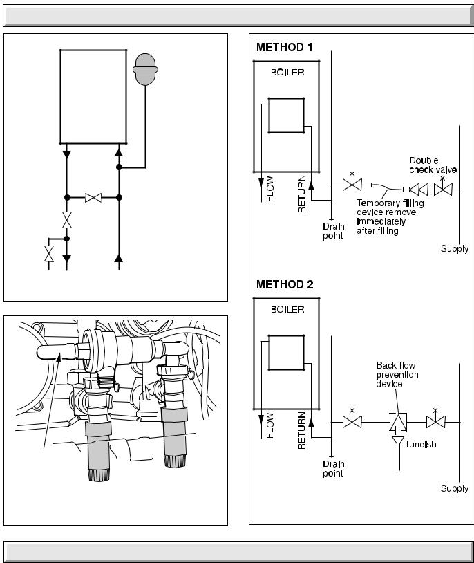
3.2 Filling the Sealed System
NOTE: The water pressure at the boiler must be at least 1.2bar to enable filling the boiler to a minimum pressure. If not pressurisation must be carried out by an alternative filling loop.
The boiler has a built in filling device, see diagram 3.3. A pushon extension is supplied in the loose items pack to ease access to the filling device tap.
This filling device is designed to enable the re-pressurisation of the system in the event of loss of pressure. It is not intended to be used to completely fill the system. If so used, it may take a long time to fill the system.
Refer to diagram 3.3. Using the tap extensions connected to tap (a) and tap (b) open tap (b) and then slowly open tap (a). Repressurise the system to a pressure of 1.0 bar indicated on the digital display with no demand. When the system is pressurised you must close tap (b) and then tap (a).
To fill the system quickly provision should be made to include a proprietry filling loop external to the boiler.
Suitableexternalfillingsystemsareshowndiagramatically,see diagram 3.4. The system should be pressurized to 1 bar, indicated on the digital display with no heating demand.
3.3 Water Treatment
In the case of an existing installation, it is ESSENTIAL that prior to installing the new boiler the system is thoroughly flushed. For optimum performance after installation of a new system, the boiler and its associated central heating system should also be flushed. Flushing should be carried out in accordance with BS7593: 1992 using a cleanser such as Sentinel X300 or X400, or Fernox Superfloc.
For long-term corrosion protection, after flushing, an inhibitor suitable for cast aluminium exchangers should be used, refer to the current issue of BS 5449 and BS 7593 on the use of inhibitors in central heating systems.
12254 |
|
WATER |
|
|
BOILER |
DOMESTIC |
|
|
Filling device |
|
|
|
|
HOT OUT |
COLD SUPPLY IN |
|
|
ADDITIONAL |
|
|
|
EXPANSION |
|
|
|
VESSEL (if required) |
|
|
|
|
|
BYPASS 
(if required)
'A'
HEATING CONTROL
CIRCUIT VALVE
RETURN |
DRAIN |
|
|
|
POINT |
Diagram 3.2
2000225294A |
16 |
3 Heating System Design
10157 |
Boiler |
Additional |
|
expansion |
|
|
|
|
|
|
vessel |
|
|
(if required) |
|
Bypass |
|
|
|
(if required) |
|
|
Control |
'A' |
|
|
valve |
Return |
||
Drain |
Flow |
||
point |
|||
Heating |
|
||
|
|
||
|
circuit |
|
Diagram 3.2a
|
12211 |
FILLING LOOP |
|
|
TAP (b) |
TAP (a) |
EXTENSION |
|
|
EXTENSION |
|
(F24e & F28e ONLY) |
Diagram 3.3 |
12253 |
TYPE CA |
Diagram 3.4 |
4 (F24e & F28e ONLY) Domestic Hot Water System Design
All domestic hot water circuits, connections, fittings must be in accordance with the relevant standards and water supply regulations.
For GB: Refer to the current addition of the Water Regulations Guide.
ForIE:ThecurrenteditionofI.S.813"DomesticGasInstallations".
-Copper tubing or plastic Hep20 may be used for the domestic hot water system. Unnecessary pressure losses should be avoided.
-Provision shall be made for a drain valve at the lowest point of the system.
- The boiler will operate with a supply pressure of 0,6 bar, but under reduced flow rate. In these circumstances the filling loop will not pressurise the boiler.
Best operating comfort will be obtained from a supply pressure of 1 bar.
4.1 Hard Water Areas
In areas where the water is 'hard', more than 200mg/litre, it is recommended that a proprietary scale reducer is fitted in the cold water supply to the boiler.
17 |
2000225294A |

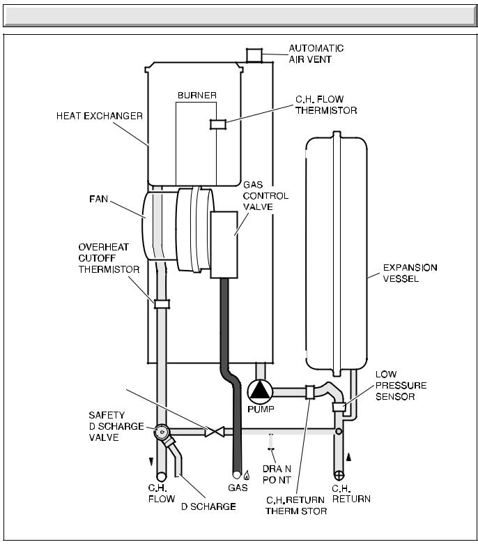
5 Boiler Schematic
|
11907 |
(F24e & F28e ONLY) |
Diagram 5.1 |
2000225294A |
18 |
5 Boiler Schematic
12248
BYPASS
|
|
|
|
|
|
|
|
|
|
|
|
|
|
|
|
|
|
|
|
|
|
|
|
|
|
|
|
|
|
|
|
|
|
|
|
|
|
|
|
|
|
|
|
|
|
|
|
|
|
|
|
|
|
|
|
|
|
|
|
|
|
|
|
|
|
|
|
|
|
|
|
|
|
|
|
|
|
|
|
|
|
|
|
|
|
|
|
|
|
|
|
|
|
|
|
|
|
|
|
|
|
|
|
|
|
|
|
|
|
|
|
|
|
|
|
|
|
|
|
|
|
|
|
|
|
|
|
|
|
|
|
|
|
|
|
|
|
|
|
|
|
|
|
|
|
|
|
|
|
|
|
|
|
|
|
|
|
|
|
|
|
|
|
|
|
|
|
|
|
|
|
|
|
|
|
|
|
|
|
|
|
|
|
|
|
|
(F28e SB ONLY) |
|
|
|
|
|
|
|
|
|
Diagram 5.1a |
||||||
|
|
|
|
|
|
|
|
|
||||||||
19 |
2000225294A |

6 Boiler Location, Flue and Ventilation
6.1 Location
This boiler is not suitable for outdoor installation.
This boiler may be installed in any room, although particular attention is drawn to the installation of a boiler in a room containing a bath or shower where reference must be made to the relevant requirements.
The boiler must NOT be installed in a cupboard.
In GB this is the current I.E.E. WIRING REGULATIONS and BUILDING REGULATIONS.
In IE reference should be made to the current edition of I.S.813 "Domestic Gas Installations" and the current ETCI rules.
The boiler must be mounted on a flat wall, which is sufficiently robust to take its weight, see diagram 1.1.
6.2 Clearances
The position of the boiler must be such that there is adequate space for servicing.
The recommended clearances are shown in diagram 6.1.
The minimum acceptable spacings from the terminal to obstructions and ventilation openings are shown in diagram 6.2. For Ireland the minimum distances for flue terminal positioning must be those detailed in I.S.813 "Domestic Gas Installations".
The terminal must be exposed to the external air, allowing free passage of air across it at all times.
Being a condensing boiler some pluming may occur from the flue outlet. This should be taken into consideration when selecting the position for the terminal.
Carports or similar extensions of a roof only, or a roof and one wall,requirespecialconsiderationwithrespecttoanyopenings, doors, vents or windows under the roof. Care is required to protect the roof if made of plastic sheeting. If the carport comprises of a roof and two or more walls, seek advice from the local gas supply company before installing the boiler.
25mm ABOVE ELBOW
11901
25mm
5mm
 600mm
600mm
300mm
Diagram 6.1
11508
MINIMUM SITING DIMENSIONS FOR THE |
|
POSITIONING OF FLUE TERMINALS |
MM |
HORIZONTAL FLUES
ADIRECTLY BELOW, ABOVE OR HORIZONTALLY TO AN OPENING, AIR BRICK,
OPENING WINDOWS, AIR VENT, OR ANY |
|
OTHER VENTILATION OPENING |
300 |
B BELOW GUTTER, DRAIN/SOIL PIPE |
75 |
C BELOW EAVES |
200 |
D BELOW A BALCONY OR CAR PORT |
200 |
E FROM VERTICAL DRAIN PIPES AND |
|
SOIL PIPES |
150 |
FFROM INTERNAL/EXTERNAL CORNERS OR TO A BOUNDARY ALONGSIDE THE
|
TERMINAL |
300 |
G |
ABOVE ADJACENT GROUND OR |
|
|
BALCONY LEVEL |
300 |
H |
FROM SURFACE OR A BOUNDARY |
|
|
FACING THE TERMINAL |
600 |
I |
FACING TERMINALS |
1200 |
J |
FROM OPENING (DOOR/WINDOW) |
|
|
IN CAR PORT INTO DWELLING |
1200 |
K |
VERTICAL FROM A TERMINAL |
1500 |
L |
HORIZONTALLY FROM A TERMINAL |
300 |
VERTICAL FLUES |
|
|
M |
FROM ADJACENT WALL TO FLUE |
300 |
N |
FROM ANOTHER TERMINAL |
600 |
P |
FROM ADJACENT OPENING WINDOW |
1000 |
Q |
ABOVE ROOF LEVEL |
300 |
TERMINAL
GUARD
Diagram 6.2
2000225294A |
20 |
 Loading...