


THEMA CLASSIC F24E PLUS
4000121771-2.02.03
Instructions for Use
Installation and Servicing
To be left with the user
Themaclassic
F24E PLUS
Fanned Flue Combination Boiler
G.C.No. 47-920-37
Themaclassic
F30E PLUS
Fanned Flue System Boiler
G.C.No. 47-920-38
Hepworth Heating Ltd., Nottingham Road, Belper, Derbyshire. DE56 1JT
Guarantee Registration
Thank you for installing a new Saunier Duval appliance in your home.
Saunier Duval appliances' are manufactured to the very highest standard so we are pleased to offer our customers’ a
Comprehensive Guarantee.
This product is guaranteed for 24 months from the date of installation or 30 months from the date of manufacture,
whichever is the shorter, for parts. In addition this product is guaranteed for 12 months from the date of installation or
18 months from the date of manufacture, whichever is the shorter, for labour.
The second year of the parts guarantee, from the beginning of the 13th month onwards after installation, is conditional
upon the boiler having been serviced by a CORGI registered gas installer, in accordance
with the manufacturer's recommendations. We strongly recommend regular servicing of your gas appliance, but where
the condition is not met, any chargeable spare parts or components issued within the applicable guarantee period still
benefit from a 12 month warranty from the date of issue by the manufacturer.
We recommend you complete and return as soon as possible your guarantee registration return literature, supplied in
If your guarantee registration return literature is missing you can obtain a copy by telephoning
Heatcall our Customer Service Company 00 44(0)1773 828100.
RECORD YOUR SAUNIER DUVAL APPLIANCE DIRECT BY CALLING
the document envelope.
0208 247 9857
Customer service :
Saunier Duval GB Great Britain :
Tel. 00 44 (0) 828100
Fax. 00 44 (0)1773 828070
Hepworth Heating Ltd.,
Nottingham Road, Belper, Derbyshire. DE56 1JT
Saunier Duval IE IRELAND:
Tel. 00 353 (0)14191919
Fax. 00 353 (0)14584806
Hevac
,
Muirfield Drive
Naas Road
Dublin 12
Technical Advice Line:
Tel. 00 44 (0)1773 828400
4000121771-2
General and Sales enquiries:
Tel. (01773) 824141
Fax. (01773) 820569
2

Contents
CONTENTS DESCRIPTION SECTION PAGE No.
Important Information 4
Draining and Filling 5
INSTRUCTION
FOR USE
INSTALLATION
INSTRUCTIONS
Appliance Introduction 5
Appliance Safety Devices 5
Maintenance and Servicing 6
Controls and Lighting 7
Programmer instructions for use 9
Technical Data 1 10
General Information 2 11
Heating System Design 3 11
Domestic Hot Water System Design 4 12
Boiler Schematic 5 13
Boiler Location, Flue and Ventilation 6 14
Fixing Jig 7 16
Boiler Preparation and System Connections 8 17
Boiler Installation 9 18
Horizontal Rear Flue Installation 10 19
Horizontal Telescopic Top Flue Installation 11 22
Horizontal Top Flue Installation 12 24
Electrical Connection 13 26
Commissioning 14 28
Boiler Settings 15 30
Changing Gas Type 16 32
SERVICING
INSTRUCTIONS
Routine Cleaning and Inspection 17 33
Fault Finding 18 37
Wiring Diagram 19 43
Replacement of Parts 20 44
Spare Parts 21 56
3
4000121771-2

Important Information
Gas safety (Installation and use) Regulations
In your interests and that of gas safety, it is the law that ALL gas
appliances are installed and serviced by a competent person in
accordance with the regulations.
Testing and Certification
This boiler is tested and certificated for safety and
performance. It is therefore important that no alteration is
made to the boiler, without permission, in writing, from
Hepworth Heating Ltd.
Any alteration not approved by Hepworth Heating Ltd., could
invalidate the certification, boiler warranty and may also
infringe the current issue of the Statutory Requirements. The
requirements are: The installation of this boiler must be
carried out by a competent person in accordance with the
current rules in force in the countries of destination at the
time of installation, for Ireland, install in accordance with
I.S.813 "Domestic Gas Installation". Manufacture's
instructions supplied must not be taken as overriding
statutory requirements.
CE Mark
This boiler meets the requirements of Statutory Instrument
No. 3083 The boiler (Efficiency) Regulations, and therefore is
deemed to meet the requirements of Directive 92/42/EEC on
the efficiency requirements for new hot water boilers fired
with liquid or gaseous fuels.
Type test for purposes of Regulation 5 certified by: Notified
body 0049.
Product/production certified by: Notified body 0049.
The CE mark on this appliance shows compliance with:
1. Directive 90/396/EEC on the approximation of the laws of
the Member States relating to appliances burning
gaseous fuels.
2. Directive 73/23/EEC on the harmonization of the Laws of
the Member States relating to the electrical equipment
designed for use within certain voltage limits.
3. Directive 89/336/EEC on the approximation of the Laws of
the Member States relating to electromagnetic compatibility.
Control of Substances Hazardous to Health
The adhesives and sealants used in this appliance are cured
and give no known hazard in this state.
Insulation pads / ceramic fibre
These can cause irritation to skin, eyes and the respiratory
tract.
If you have a history of skin complaint you may be susceptible to irritation. High dust levels are usual only if the material
is broken.
Normal handling should not cause discomfort, but follow
normal good hygiene and wash your hands before eating,
drinking or going to the lavatory.
If you do suffer irritation to the eyes or severe irritation to the
skin seek medical attention.
The insulation is composed of non-combustible material.
Electrical Supply
WARNING: This boiler must be earthed.
All system components shall be of an approved type and shall
be connected in accordance with the current issue of BS7671
and any applicable local regulations.
All external wiring between the appliance and the electrical
supply and earthing requirements shall comply with the current
IEE Regulations.
Connection of the boiler and system controls to the mains
supply must be through a common isolator and must be fused
at 3A, maximum. This method of connection must be by a fused
double pole isolating switch, with a minimum contact separation
of 3mm on both poles. The switch should be readily accessible
and preferably adjacent to the appliance. It should supply the
appliance only and be easily identifiable as so doing.
Alternatively, an unswitched shuttered socket outlet and 3A
fused 3 pin plug, both to the current issue of BS1363 may be
used provided that they are not used in a room containing a bath
or shower.
Wiring to the boiler must be PVC 85oC insulated cable, not less
than 0.75mm2 (24/0.20mm).
Gas leak or fault
WARNING: If a gas leak or fault exists or is suspected, turn the
boiler off and consult the local gas supply company or your
installation/service company.
Manual Handling Guidance
During the appliance installation it will be necessary to employ
caution and assistance whilst lifting as the appliance exceeds
the recommended weight for a one man lift.
In certain situations it may be required to use a mechanical
handling aid.
Take care to avoid trip hazards, slippery or wet surfaces.
Heating System Controls
The heating system must be controlled as described in the
relevant part of the current issue of :
Building Regulations, approved document L1, and the
references:
1) GIL 59, 2000: Central heating system specification (CheSS)
and
2) GPG 302, 2001: Controls for domestic central heating
system and hot water. BRECSU.
3) The domestic heating and hot water guide to the building
regulations 2001.
Thermostatic radiator valves may be installed, however they
must not be fitted in a room where the room thermostat is
located.
Air in the heating system
Persistent air in the heating system may indicate leaks in the
system or corrosion taking place. Call your Installation/Servicing
company.
Protection Against Freezing
The appliance has a built in frost protection programme as long
as the electricity and gas are left switched on.
This device operates the burner and system pump when the
temperature inside the boiler falls below 60C.
Any other exposed areas of the system should be protected by
a separate frost thermostat.
4000121771-2
4
Draining and Filling
Caution: The boiler is installed as part of a sealed system
which must only be drained and filled by a competent person.
If the mains electricity and gas are to be turned off for any long
periods during severe weather, it is recommended that the
whole system, including the boiler, refer to diagram 1, should
be drained to avoid the risk of freezing. Make sure that, if fitted,
the immersion heater in the cylinder is switched off.
If in doubt, consult your servicing company.
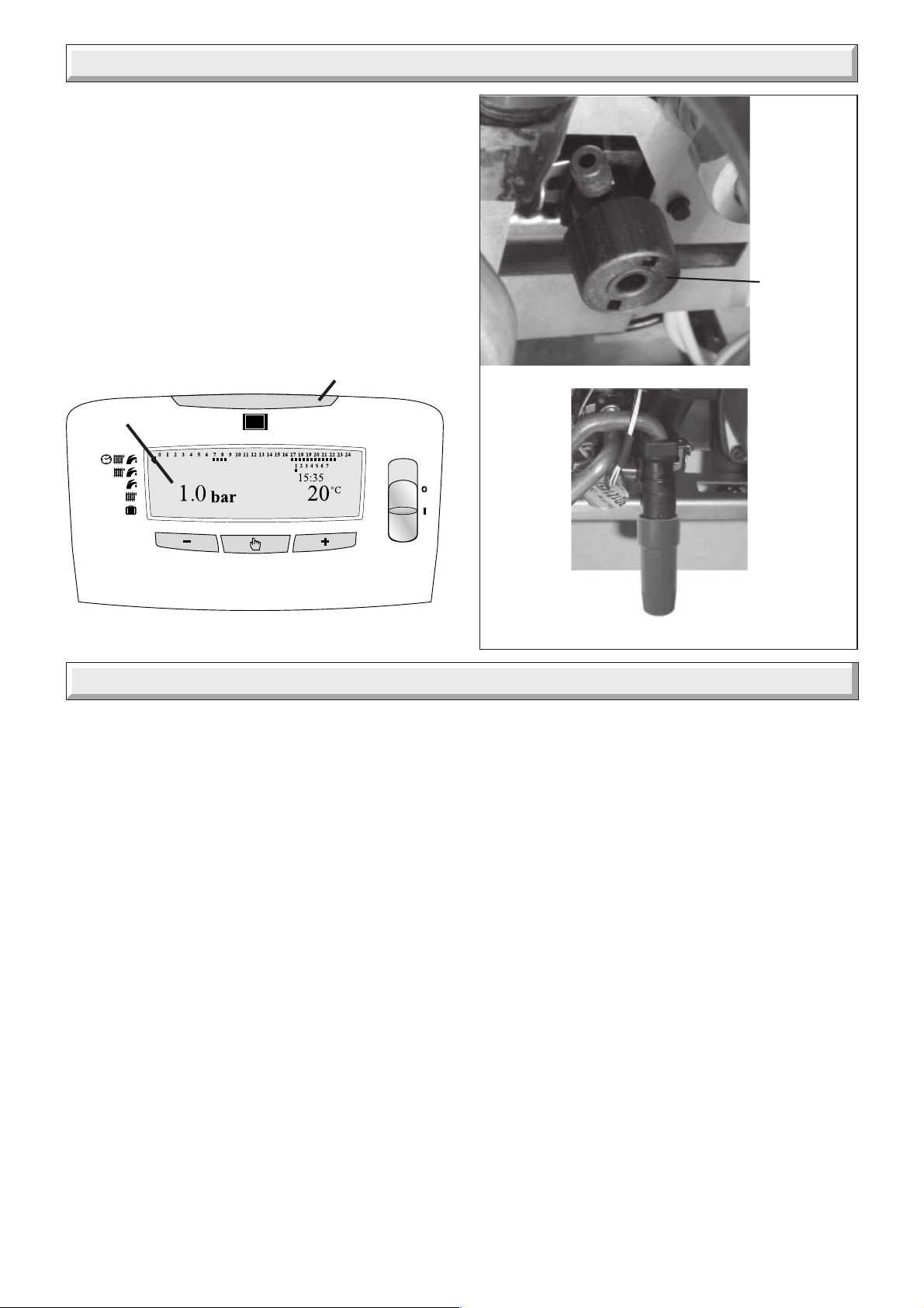
• If the boiler loses water: the pressure will be indicated (a)
and the boiler ON indicator (b) will flash red indicating a fault.
Fill the system by the filling device (c) at the bottom of the boiler
until the pressure gauge reads 1.0 bar.
Reset boiler: refer to diagram 2, switch On/Off to ( 0 ), wait for
five seconds. Switch On/Off to ( I ) to reset the appliance.
(b)
(a)
11900
BOILER
DRAIN
VALVE
Appliance Introduction
The Themaclassic plus boiler is a wall mounted modulating
combination boiler with electronic ignition providing central
heating and instantaneous hot water.
The boilers are equipped with a litre domestic hot water
storage vessel that ensures maximum hot water temperature
stability during domestic demand.
The boiler is of the II
as distributed in the United Kingdom, or Butane (G30), Propane
(G31) with the appropriate conversion kit.
The boiler has a fan assisted balanced flue which both discharges
the products of combustion to and draws the combustion air
from the outside of the room.
Both the central heating and domestic hot water temperature
are user adjustable.
Domestic hot water demand always has priority over heating
demand.
The boiler is designed for use as part of a sealed water central
heating system with fully pumped circulation. The pump,
expansion vessel and associated safety devices are all fitted
within the boiler.
The boiler can be installed against either an external wall or on
an adjacent inside wall, that is, the flue system will pass directly
to the rear or to either side to the terminal fitted on the outside
wall face.
category for use with Natural Gas (G20)
2H3+
➜
(c)
Diagram 1
This boiler may be installed in any room, although particular
attention is drawn to the installation of a boiler in a room
containing a bath or shower where reference must be made to
the relevant requirements.
Any electrical switch or boiler control utilising mains electricity
should be placed so that it cannot be touched by a person using
the bath or shower.
In GB this is the current I.E.E. WIRING REGULATIONS and
BUILDING REGULATIONS.
In IE reference should be made to the current edition of I.S.813
"Domestic Gas Installations" and the current ETCI rules.
These instructions should be carefully followed for the safe and
economical use of your boiler. The 'User Controls and Lighting'
section describes how to safely use the boiler.
Note: The boiler serial number is marked on the data label
attached to the rear of the control box.
Flue options
There are various flue systems to choose from, for detailed
information refer to flue options guide, which is available
from your nearest stockist.
Accessories
A range of accessories are available.
For further information contact your supplier.
5
4000121771-2

Appliance Safety Devices
Air flow rate safety device
If the flue is obstructed, even partially, the built in safety system
will turn the boiler OFF, the fan will continue to run. The boiler
will be ready to operate when the fault has been cleared.
Overheating safety
In the event of the boiler overheating the safety devices will
cause a safety shutdown. If this happens, call your Installation/
Servicing company.
Electrical supply failure
The boiler will not operate without an electrical supply. Normal
operation of the boiler should resume when the electrical
supply is restored.
Reset any central heating system controls, to resume normal
operation.
If the boiler does not resume normal operation turn the mains
reset switch off and on. If the boiler does not resume normal
operation it is advisable to consult your installation / servicing
company.
Frost protection
The appliance has a built in frost protection device that
protects the boiler from freezing. With the gas and electric
supplies ON and irrespective of any room thermostat setting,
the frost protection device will light the boiler when the
temperature of the boiler water falls below 6°C.
When the temperature reaches 16°C, the boiler stops.
Any other exposed areas of the system should be protected by
a separate frost thermostat.
Heating safety valve
CAUTION: A heating safety valve with a discharge pipe is fitted
to this boiler.
The valve MUST NOT BE TOUCHED except by a competent
person. If the valve discharges at any time, switch the boiler off
and isolate it from the electrical supply. Contact your installation/
service company.
Domestic Hot Water safety valve
CAUTION: A domestic hot water safety valve, with a discharge
pipe is fitted to this boiler.
The valve MUST NOT BE TOUCHED except by a competent
person. If the valve discharges at any time, switch the boiler off
and isolate it from the electrical supply. Contact your installation/
service company.
Maintenance and Servicing
Cleaning
WARNING: This appliance contains metal parts (components)
and care should be taken when handling and cleaning with
particular regard to edges of sheet metal parts to avoid any
possibility of personal injury.
The boiler casing can be cleaned with a damp cloth, followed by
a dry cloth to polish.
Do not use abrasive or solvent cleaners.
Maintenance and Servicing
To ensure the continued efficient and safe operation of the
appliance it is recommended that it is checked and serviced as
necessary at regular intervals but in general once a year should
be enough, refer to guarantee registration on the inside front
cover of this literature.
If this appliance is installed in a rented property there is a duty
of care imposed on the owner of the property by the current
issue of the Gas Safety (Installation and Use) Regulations,
Section 35.
Servicing/maintenance should be carried out by a competent
person in accordance with the rules in force in the countries of
destination.
To obtain service, please call your installer or Heatcall (Saunier
Duval’s own service organisation) using the telephone number
on the inside front cover of this literature.
Please be advised that the ‘Benchmark’ logbook should be
completed by the engineer on completion of commissioning
and servicing.
All CORGI Registered Installers carry a CORGI ID card, and
have a registration number. Both should be recorded in your
benchmark Logbook. You can check your installer is CORGI
registered by calling CORGI direct on: 01256 372300.
Spare Parts
REMEMBER, When replacing a part on this appliance, use only
spare parts that you can be assured conform to the safety and
performance specification that we require. Do not use
reconditioned or copy parts that have not been clearly authorised
by Hepworth Heating Ltd.
If a part is required contact Heatcall (Saunier Duval’s own
service organisation) using the telephone number on the inside
front cover of this booklet.
Please quote the name of the appliance, this infomation will be
on the name badge on the front of the appliance.
If in doubt seek advice from the local gas company or Heatcall
(Saunier Duval’s own service organisation) using the telephone
number on the inside front cover of this booklet.
4000121771-2
6
Controls and lighting
Central heating adjustment
The temperature of the water in the central heating circuit can
be set between, approx. 38OC and 87OC.
It is supplied, factory set to 38OC - 73OC
Domestic hot water
The temperature can be adjusted from approx. 38°C up to
65°C.
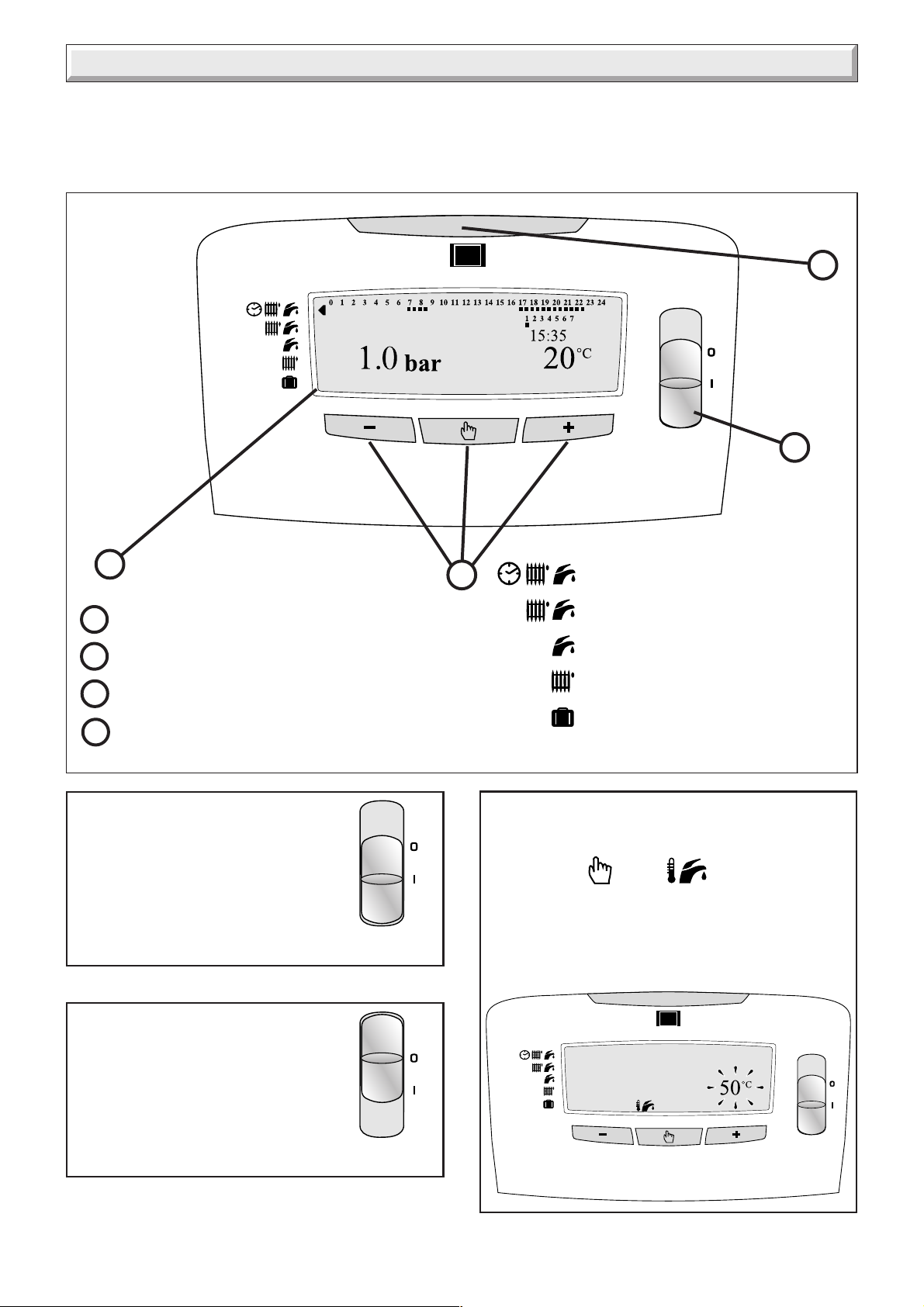
11524
4
1
2
1 - OFF/ON switch
2 - Display
3 - Programing buttons
4 - Running lamp illuminated green when boiler
is ON (flashing red when fault indicated)
1. Lighting the boiler:
Make sure that:
• The boiler is connected to the electrical
supply.
• The gas service cock is open.
Switch ON (I)
The running lamp will illuminate green.
3
11444
Timed central heating and
instantaneous domestic hot water
Central heating and
domestic hot water
Domestic hot water only
Central heating only
Long absence / Holiday mode
and Appliance frost protection
Diagram 2
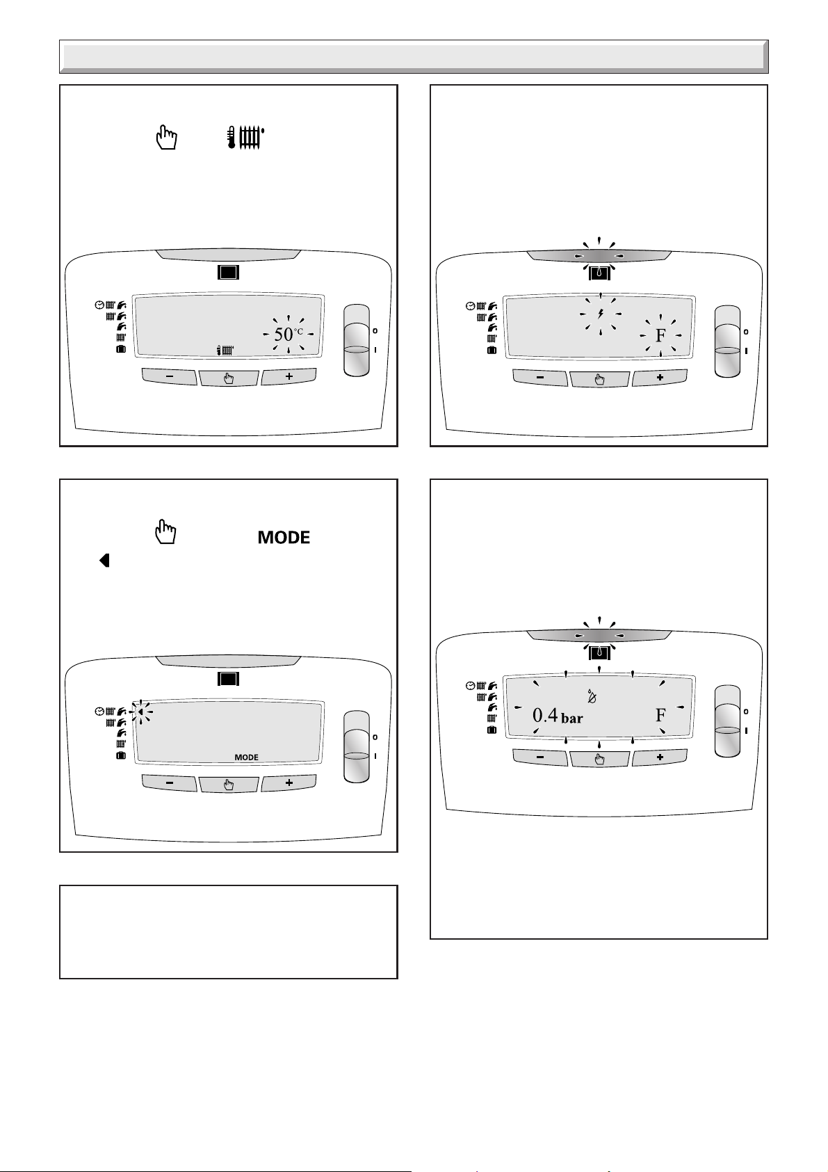
3. Domestic hot water temperature
adjustment:
• Press button once, is displayed and the
current temperature setting flashes.
• Press - or + to set a temperature between 38°c to 65°c.
• The display will default to normal after 5 seconds if no
buttons are pressed.
2. Stop the boiler:
• Switch to OFF (0) the electrical supply is
OFF.
18
11445
7
11525
4000121771-2
Controls and lighting
4. Central heating temperature adjustment:
• Press button twice, is displayed and the
current temperature setting flashes.
• Press - or + to set a temperature between 38°c to 87°c.
• The display will default to normal after 5 seconds if no
buttons are pressed.
5. Heating Mode select:
• Press button three times, is displayed
and will flash along side the current mode setting.
• Press - or + to set as required.
• The display will default to normal after 5 seconds if no
buttons are pressed.
11526
7. If a fault occurs:
• The green running light will change to a red flashing light
and the display will flash the letter ‘F’ with the type of fault.
• Reset the boiler: Switch the boiler OFF ( 0 ), wait for five
seconds. Switch the boiler ON ( I ), the boiler is reset. If the
fault continues call your Installation/Servicing company or
Heatcall using the telephone number on the inside front
cover of this literature.
11528
(Ignition fault shown)
8. Installation filling:
• If the boiler loses water: The green running light will
change to a red flashing light and the display will flash the
letter ‘F’ with the low system water pressure fault and the
current system pressure.
• Fill the system by the filling device at the bottom of the
boiler until the pressure gauge reads 1.0 bar.
6. Long absence / Holiday mode:
• This mode protects the boiler against frost
11529
11527
• Warning: Take care not to overfill the boiler. At a
pressure of 2.5 bar or above the high system water
pressure fault will be displayed. The pressure must be
reduced to 1.0 bar by opening the drain valve, see diagram
1. If the fault continues call your Installation/Servicing
company or Heatcall using the telephone number on the
inside front cover of this literature.
4000121771-2
8

Programmer instructions for use
Setting the time.
Make sure there is an electrical supply to the boiler and the
boiler is switched ON ( I ).
Press button four times, is displayed and the time
will flash, press - or + to set the correct time (24hr clock).
press "+" and , and the will be
displayed along with 0 to 24 hour ON / OFF settings and 1 to 7
days of the week.
Set ON / OFF times at 30min intervals for each day 1 to 7 of the
week.
A flashing square is displayed below the current day of the
11530
11538
Setting the day.
Press button five times, is displayed and the
current day setting will flash, press - or + to set the correct day.
1=MON, 2=TUE, 3=WED, 4=THU, 5=FRI, 6=SAT, 7=SUN
Setting the programmer.
Press button six times, is displayed.
week selected, Press - or + to select the day 1 to 7 to be set.
Press to set ON / OFF times, and are
displayed, a flashing square will now be displayed below the 0
along the top of the display along with the corresponding time
00:00
00:30 is set to OFF, to set this to ON press + , or to set
11536
to OFF press - , continue setting the ON / OFF times
11537
for the remainder of that day / 24hr period in 30min intervals.
to the right of the display, this indicates that 00:00 to
OFF
11539
Press , and is displayed, press + to select
the next day or - to select the previous day to be set, continue
setting the remaining days as required.
The display will default to normal after 60 seconds if no buttons
are pressed.
9
4000121771-2
1 Technical Data
Heating F24E PLUS F30E PLUS
Heat input (max) NET Q 25,9 kW 32,6 kW
88,370 BTU/H 111,231 BTU/H
Heat input (min) NET Q 12,3 kW 12,5 kW
41,967 BTU/H 42,650 BTU/H
Heat output (max) GROSS P 23,6 kW 29,6 kW
80,523 BTU/H 100,995 BTU/H
Heat output (min) GROSS P 10,6 kW 10,3 kW
31,731 BTU/H 35,144 BTU/H
Efficiency - Sedbuk D 78,3% 79,6%
Maximum heating temperature 87° C87° C
Expansion vessel effective capacity 6,5 l 8 l
Expansion vessel charge pressure 0,5 bar 0,5 bar
Maximum system capacity at 75°C 125 l 156 l
RED Safety valve, maximum service pressure 3 bar 3 bar
Hot water F24E PLUS F30E PLUS
Heat input (max) NET Q 25,9 kW 32,6 kW
88,370 BTU/H 111,231 BTU/H
Heat input (min) NET Q 12,3 kW 12,5 kW
41,967 BTU/H 42,650 BTU/H
Heat output (max) GROSS P 23,6 kW 29,6 kW
80,523 BTU/H 100,995 BTU/H
Heat output (min) GROSS P 10,6 kW 10,3 kW
31,731 BTU/H 35,144 BTU/H
Maximum hot water temperature 65° C65° C
Minimum hot water temperature 38° C38° C
Specific flow rate (for 30° C temp rise) 11,3 l/min. 14,1 l/min.
Threshold flow rate 1,7 l/min. 1,7 l/min.
Maximum supply pressure 10 bar 10 bar
Minimum supply pressure 0,5 bar 0,5 bar
BLUE Safety valve, 10 bar 10 bar
Combustion F24E PLUS F30E PLUS
Products outlet diameter 60 mm 60 mm
Fresh air inlet diameter 100 mm 100 mm
Combustion products values CO (24 ppm) CO (40 ppm)
CO2 (6,9%) CO2 (7,6%)
NOx (99ppm) NOx (81ppm)
Net lift weight (boiler only)
39 kg (F24E) 41 kg (F30E)
Gross lift weight (boiler and packaging)
41 kg (F24E) 43 kg (F30E)
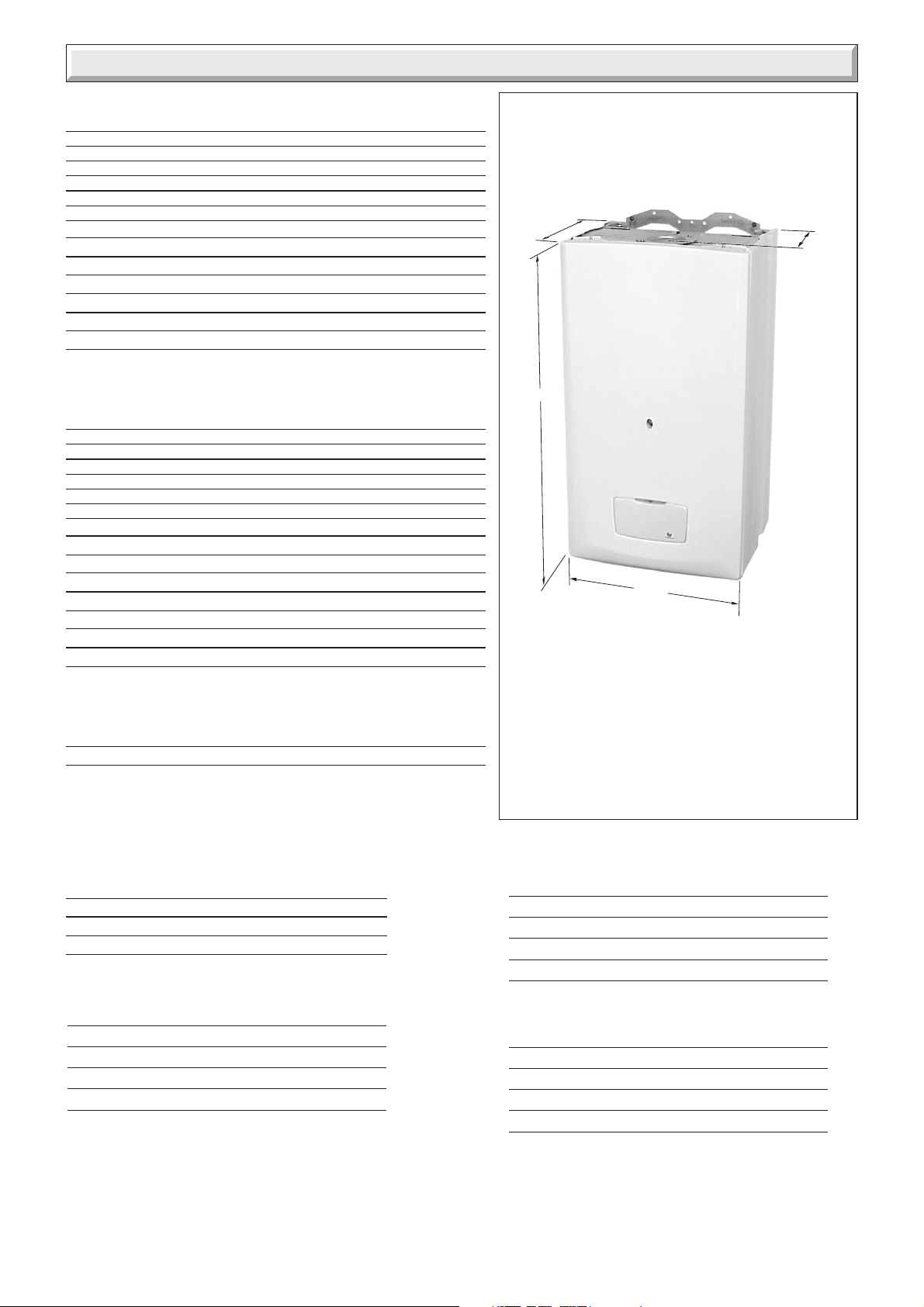
365
232
11564a
798
450
The Themaclassic F24E Plus and
Themaclassic F30E Plus
is delivered in two separate packages:
• The boiler hanging bracket and isolating
valves.
• The flue system
Diagram 1.1
Electrical F24E PLUS - F30E PLUS
Electrical supply 230 V ~ 50Hz
Electrical rating 105 W(F24E) 135 W(F30E) fused at 3A
Level of protection IPX4D
Fuse rating 1,25mA
Natural Gas (G20) F24E PLUS F30E PLUS
Ø Burner injector 1,2 mm 1,2 mm
Inlet pressure 20 mbar 20 mbar
Maxi. Burner pressure 12,5 mbar 13,3 mbar
Mini. Burner pressure 2,35 mbar 2,15 mbar
Gas rate maximum 2,74 m3/h 3,45 m3/h
4000121771-2
Butane Gas (G30) F24E PLUS F30E PLUS
Ø Burner injector 0,73 mm 0,73 mm
Inlet pressure 29 mbar 29 mbar
Maxi. Burner pressure 23,2 mbar 25,5 mbar
Mini. Burner pressure 4,5 mbar 3,73 mbar
Gas rate maximum 2,03 kg/h 2,57 kg/h
Propane Gas (G31) F24E PLUS F30E PLUS
Ø Burner injector 0,73 mm 0,73 mm
Inlet pressure 37 mbar 37 mbar
Maxi. Burner pressure 29,8 mbar 32,5 mbar
Mini. Burner pressure 5,7 mbar 4,7 mbar
Gas rate maximum 2,01 kg/h 2,53 kg/h
10

2 General Information
IMPORTANT NOTICE.
Where no British Standards exists, materials and equipment
should be fit for their purpose and of suitable quality and
workmanship.
Refer to Manual Handling Operations, 1992 regulations.
The installation of this boiler must be carried out by a competent
person in accordance with the rules in force in the countries of
destination.
Manufacturer’s instructions must not be taken as overriding
statutory requirements.
2.1 Sheet Metal Parts
WARNING: When installing the appliance, care should be
taken to avoid any possibility of personal injury when handling
sheet metal parts.
2.2 Statutory Requirements
The appliance is suitable only for installation in GB and IE and
should be installed in accordance with the rules in force.
In GB the installation of the boiler MUST be carried out by a
competent person as discribed in the following regulations:
Manufacturer’s instructions, supplied.
The Gas Safety (Installation and Use) Regulations.
The appropriate Building Regulations, either The Building
Regulations, The Building Regulations (Scotland), The building
Regulations (Nothern Ireland).
The Water Fittings Regulations or Water Bylaws in Scotland.
The Health and Safety at Work Act, Control of Substances
Hazardous to Health (COSHH).
The Current I.E.E. Wiring Regulations.
Where no specific instructions are given, reference should be
made to the relevant British Standard Code of Practice.
In I.E the installation must be carried out by a competent person
and installed in accordance with the current edition of I.S. 813
"Domestic Gas Installations", the current Building Regulations
and reference should be made to the current ETCI rules for
electrical installation.
In GB the following Codes of Practice apply:
BS4814, BS5440 Part 1 and 2, BS5449, BS5546 Part 1, BS6700,
BS6798, BS6891 and BS7074 Part 1 and 2, BS7478, BS7593,
BS7671.
In IE: I.S.813, BS5546, BS5449, BS7074, BS7593.
Manufacturer’s notes must not be taken as overriding statutory
requirements.
BSI Certification
This boiler certificated to the current issue of EN 483 for
performance and safety.
It is important that no alteration is made to the boiler, without
permission, in writing, from Hepworth Heating Ltd.
Any alteration that is not approved by Hepworth Heating Ltd.,
could invalidate the warranty and could also infringe the current
issue of the Statutory Requirements.
2.3 Gas Supply
The gas installation must be in accordance with the relevant
standards.
In GB this is BS 6891.
In IE this is the current edition of I.S.813 "Domestic gas
installation".
The supply from the governed meter must be of adequate size
to provide a steady inlet working pressure of 20mbar (8in wg) at
the boiler.
Important Notice
If your boiler has been converted to use L.P.G. Propane the
following note applies:
Propane cylinders are under pressure and should never be
stored or used indoors residentially.
They should only be kept outside.
Under no circumstances should L.P.G. Propane cylinders be
fitted or stored in basement areas or boiler houses.
On completion, test the gas installation for soundness using the
pressure drop method and suitable leak detection fluid, purge in
accordance with the above standard.
3 Heating System Design
• The Themaclassic plus is for use with sealed central heating
systems.
• Heating surfaces may consist of radiators, convectors or fan
assisted convectors.
• The safety valves are an integral part of the boiler and cannot
be adjusted.
• The circulation pump is integral with the boiler.
• Pipe sectional areas shall be determined in accordance with
normal practices, using the output/pressure curve
(diagram 3.1). The distribution system shall be calculated in
accordance with the output requirements of the actual system,
not the maximum output of the boiler. However, provision shall
be made to ensure sufficient flow so that the temperature
difference between the flow and return pipes be less than or
equal to 20°C. The minimum flow is shown in Table 1.
The system can be fitted with a lockable balancing valve if
necessary in the main flow or return pipes shown as valve 'A'
in diagram 3.2.
• The piping system shall be routed so as to avoid any air
pockets and facilitate permanent venting of the installation.
Bleed fittings must be provided at every high point of the
system and on all radiators.
• The total volume of water permitted for the heating system
depends, amongst other things, on the static head in the cold
condition. The expansion vessel on the boiler is pressurised at
0.5 bar and allows a maximum system volume of 156 litres for
an average temperature of 75°C and a maximum service
pressure of 3 bar. This pressure setting can be modified at
commissioning stage if the static head differs. An additional
expansion vessel can be fitted to the system if required, see
diagram 3.2.
• Provision shall be made for a drain valve at the lowest point of
the system.
• Where thermostatic radiator valves are fitted, not all radiators
must be fitted with this type of valve, and in particular, where
a room thermostat is installed.
• In the case of an existing installation, it is ESSENTIAL that the
system is thoroughly flushed prior to installing the new boiler,
Using a proprietary product such as Fernox or Sentinel. Contact
11
4000121771-2
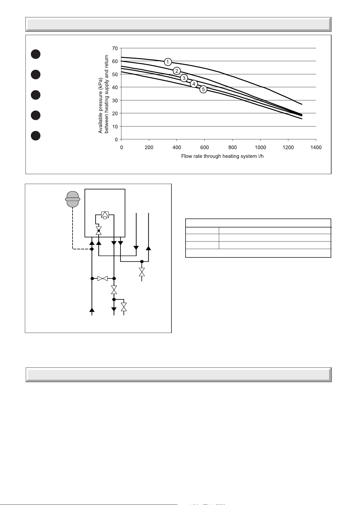
3 Heating System Design
Bypass fully shut
1
Open 1/4 turn
2
Open 1/2 turn
3
Open 1 turn
4
Open 2 turns
5
Additional
expansion
vessel
(if required)
(10 kPa = 1 m WG)
Boiler
Filling device
Domestic
water
Hot water out
Cold supply in
the product manufacturers for specific details.
3.1 Bypass
10015
•The boiler is fitted with an adjustable automatic bypass.
TABLE 1. FLOW RATE
Model Minimum flow rate
F 24 E plus ?
F 30 E plus 21.26 litres per minute
This is equal to 20°C differential at maximum heat input
11357
Diagram 3.1
* Bypass
(If required)
*
Bypass
valve
Return
Heating
circuit
'A'
Flow
Drain
point
Control
valve
Drain
point
Diagram 3.2
4 Domestic Hot Water System Design
• Copper tubing or plastic Hep20 may be used for the domestic
hot water system. Unecessary pressure losses should be
avoided.
• Provision shall be made for a drain valve at the lowest points
of the system.
• The flow restrictor must be fitted limiting the flow through the
boiler to a maximum of 12 l/min (F30E Plus)
10 l/min (F24E Plus).
Ensure that under no circumstances does the flow rate drop
below the figure specified, see Table 1.
• A bypass is not required on the central heating circuit unless
the system controls could allow the boiler to operate when
there is no flow.
• Where a bypass has to be fitted, the bypass must be placed
at least 1.5 metres from the appliance, see diagram 3.2.
3.2 Filling the system
A filling device is fitted to the boiler to initially fill the system and
replace water lost during servicing, see the relevant parts of
diagram 2 controls and lighting and diagram 3.2.
• The boiler will operate with a minimum supply pressure of 0,5
bar, at reduced flow rate.
Best operating comfort will be obtained from a supply pressure
of 1 bar.
4.1 Hard Water Areas
In areas where the water is 'hard', more than 200mg/litre, it is
recommended that a proprietary scale reducer is fitted in the
cold water supply to the boiler.
4000121771-2
12
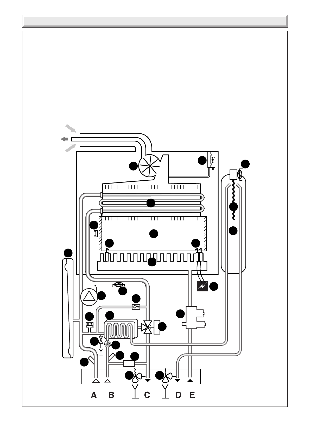
5 Boiler Schematic
1 - Fan.
2 - Air pressure switch.
3 - Heat exchanger.
4 - Overheat thermostat.
5 - Combustion chamber.
6 - Expansion vessel.
7 - Flame sense electrode.
8 - Burner.
9 - Ignition electrode.
10 - Pump.
11 - Heating thermistor.
12 - Ignition unit.
13 - By-pass.
14 - Gas valve.
15 - Loss of water sensor.
16 - Domestic heat exchanger
17 - 3 way valve
18 - Domestic water flow sensor
19 - Filter cold water inlet
20 - Filling system
21 - Discharge safety valve (3bar)
22 - Drain valve
23 - Heating filter
24 - Domestic safety valve 10 bar
25 - Micro accumulation vessel thermistor
26 - Micro accumulation vessel
27 - Heating element
A - Heating return
B - Cold water inlet
C - Heating flow
D - Domestic hot water outlet
E - Gas
2
1
25
11422
FITTED TO
REAR OF
APPLIANCE
3
4
5
27
26
FITTED TO
REAR OF
APPLIANCE
97
6
8
12
11
15
10
16
13
14
17
22
18
23
19
20
21 24
13
Diagram 5.1
4000121771-2
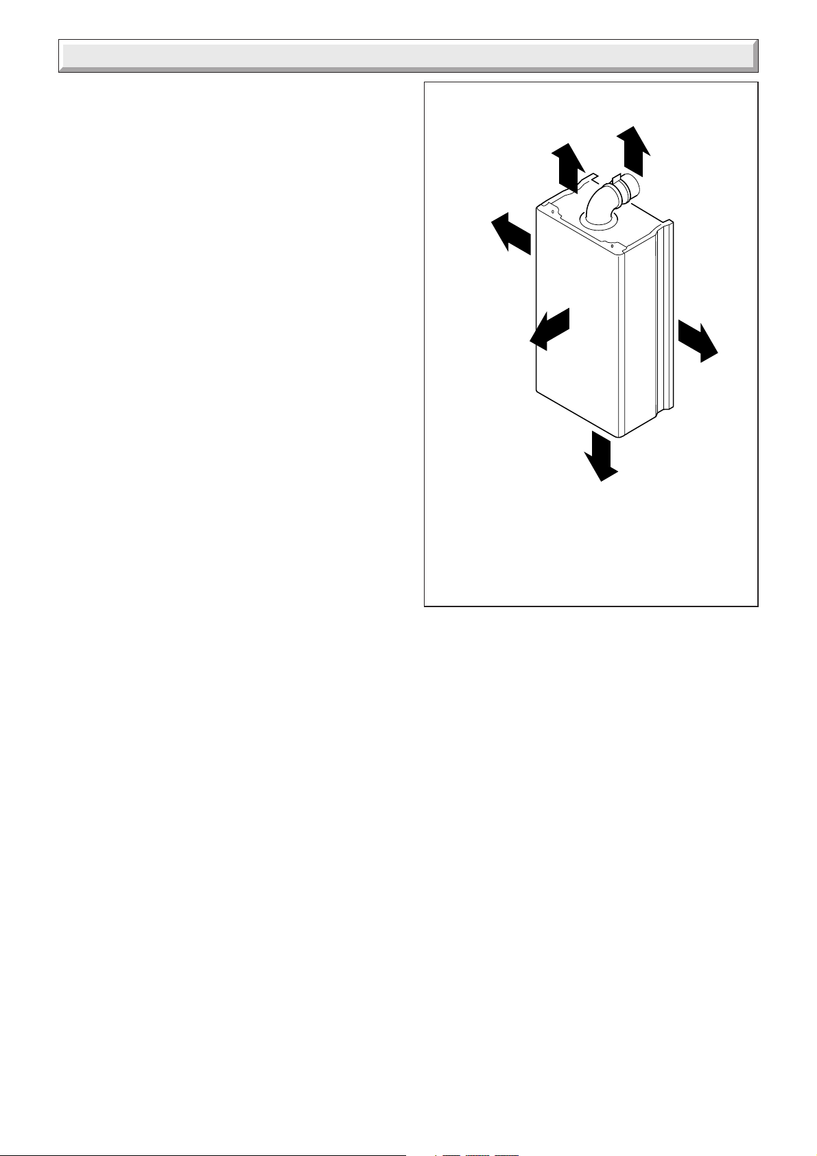
6 Boiler Location, Flue and Ventilation
6.1 Boiler Location
The recommended clearances are shown in diagram 6.1.
Note: The boiler must be mounted on a flat wall which is
sufficiently robust to take its weight when full. If in doubt, expert
advice should be obtained, in the event of the wall being found
not suitable.
The minimum acceptable spacings from the terminal to
obstructions and ventilation openings are shown in diagram
6.2. For Ireland the minimum distances for the flue terminal
positionning must be those detailed in I.S.813 "Domestic Gas
Installations".
The boiler must be installed so that the terminal is exposed to
the external air.
300mm
50mm
*
above boiler
(rear flue only)
20mm
5mm
*
11651
25mm
above
elbow
600mm
450mm
*
300mm
20mm
5mm
*
*Note: It is permissible to install the boiler with smaller
clearances than those quoted PROVIDING that
consideration is given for Servicing/Repairs.
Diagram 6.1
4000121771-2
14
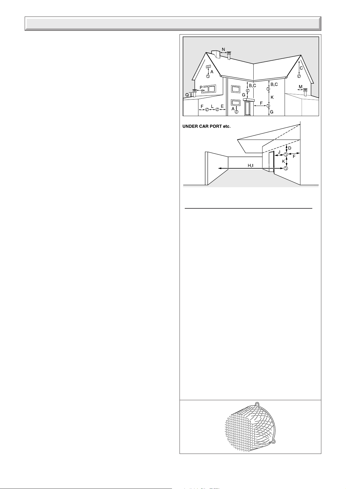
6 Boiler Location, Flue and Ventilation
6.2 Terminal guard, see diagram 6.3.
A terminal guard is required if persons could come into contact
with the terminal or the terminal could be subject to damage.
If a terminal guard is required, it must be positioned to provide
a minimum of 50mm clearance from any part of the terminal and
to be central over the terminal.
A suitable terminal guard type K3 can be supplied by:
Tower flue components Ltd.
Morley road
Tonbridge
Kent
TN9 1RA
6.3 Flue options
There are various flue systems to choose from as follows:
Horizontal rear flue pack.
Horizontal telescopic top flue pack.
Horizontal top flue pack.
Horizontal extended flue pack.
Vertical flue pack.
Twin flue pack.
Extensions, 90° and 45° bends.
For detailed information refer to flue options guide. This is
available from your nearest stockist.
6.4 Cupboard or compartment ventilation
The boiler can be fitted in a cupboard or compartment without
the need for permanent ventilation.
11508
MINIMUM SITING DIMENSIONS FOR THE
POSITIONING OF FLUE TERMINALS MM
HORIZONTAL FLUES
A DIRECTLY BELOW, ABOVE OR
HORIZONTALLY TO AN OPENING, AIR BRICK,
OPENING WINDOWS, AIR VENT, OR ANY
OTHER VENTILATION OPENING 300
B BELOW GUTTER, DRAIN/SOIL PIPE 75
C BELOW EAVES 200
D BELOW A BALCONY OR CAR PORT 200
E FROM VERTICAL DRAIN PIPES AND
SOIL PIPES 150
F FROM INTERNAL/EXTERNAL CORNERS
OR TO A BOUNDARY ALONGSIDE THE
TERMINAL 300
G ABOVE ADJACENT GROUND OR
BALCONY LEVEL 300
H FROM SURFACE OR A BOUNDARY
FACING THE TERMINAL 600
I FACING TERMINALS 1200
J FROM OPENING (DOOR/WINDOW)
IN CAR PORT INTO DWELLING 1200
K VERTICAL FROM A TERMINAL 1500
L HORIZONTALLY FROM A TERMINAL 300
VERTICAL FLUES
M FROM ADJACENT WALL TO FLUE 300
N FROM ANOTHER TERMINAL 600
P FROM ADJACENT OPENING WINDOW 1000
Q ABOVE ROOF LEVEL 30 0
15
Diagram 6.2
Diagram 6.3
4000121771-2
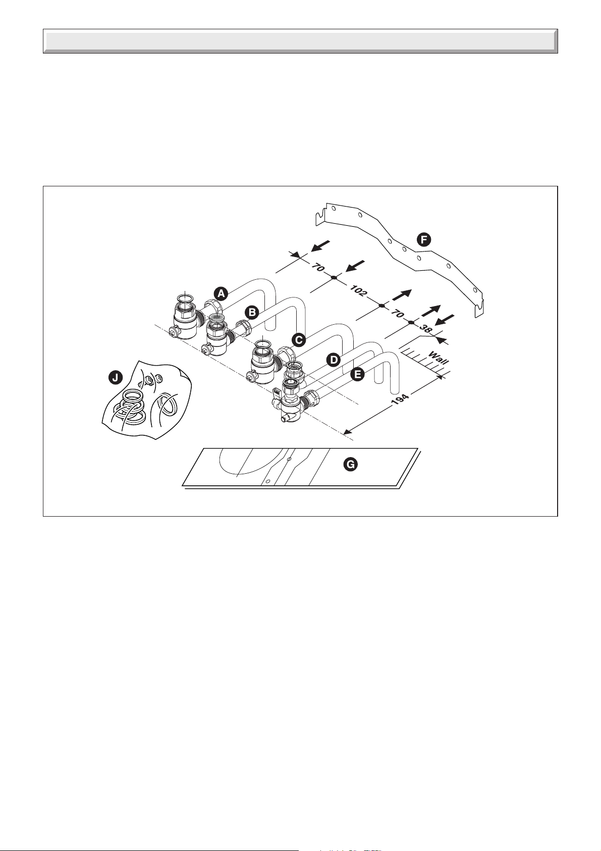
7 Fixing Jig
The fixing jig is made up as follows:
A - Heating return fitting with isolating valve.
B - Cold water inlet fitting with isolating valve.
The cold water inlet restrictor supplied with boiler is
fitted when the boiler is installed. Refer to Section 9.
C - Heating flow fitting with isolating valve.
D - Domestic hot water outlet.
E - Gas service cock.
Other components within the fixing jig pack.
F - Hanging bracket
G - wall template
J - sealing washers and screws
Diagram 7.1
4000121771-2
16
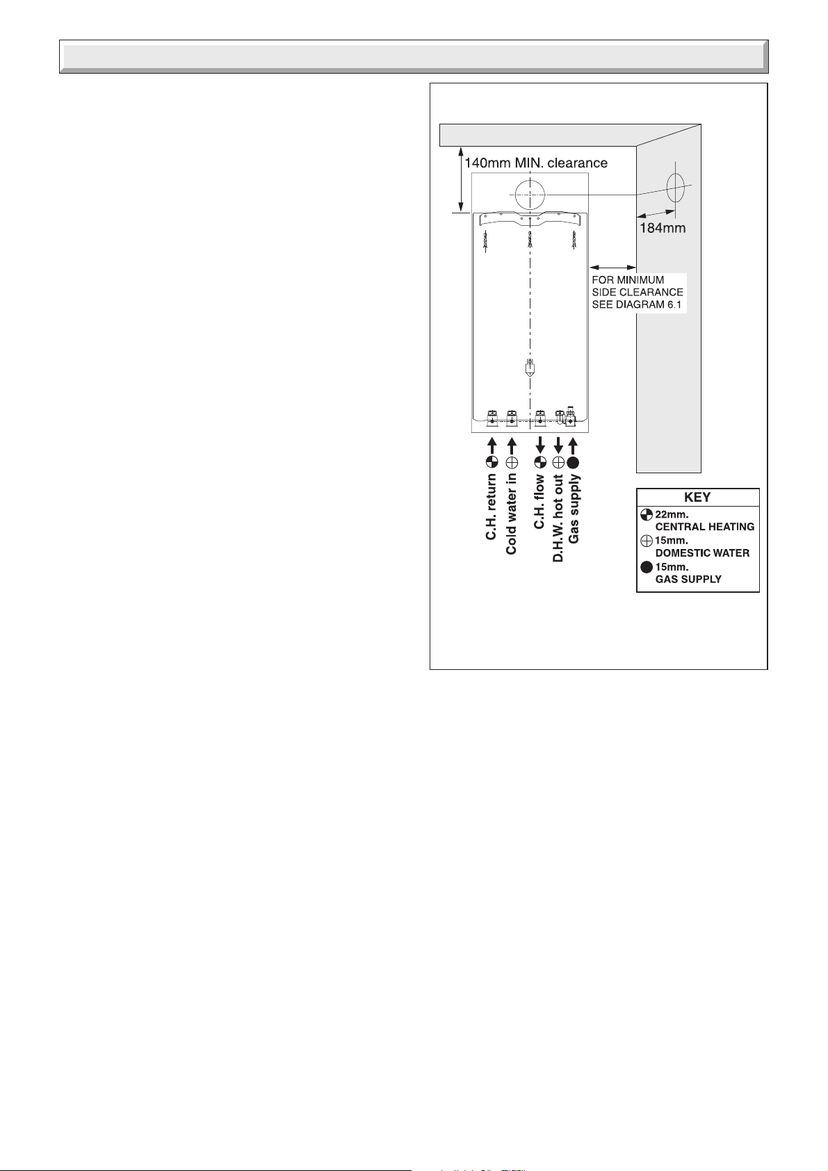
8 Boiler Preparation and System Connections
8.1 Cutting the flue hole
• Remove the wall template, follow the instructions given on the
wall template.
• Position the wall template, taking due regard of the minimum
clearances for the selected flue application, see diagram 8.1.
• Horizontal Rear hole cutting
• Mark position of Rear flue outlet hole from template, then
remove template, before cutting, for use, later. The core drill
used should be 115 mm diameter.
• Top Outlet Side / Rear hole cutting
• Mark the centre line for the hole on the wall. Extend the
horizontal centre line to the side wall if required and mark the
vertical centre line of the hole as shown in diagram 8.1.
• Making allowance for the slope of the flue, cut hole in wall,
preferably using a core drill. For installations with internal and
external access use a 105mm diameter core drill. For installations
with only internal access use a 125mm diameter core drill.
IMPORTANT NOTE: When cutting the flue hole and when
extending the flue centre line to a side wall, remember that the
flue system must have a fall of about 35mm per metre of flue
downward towards the terminal. There MUST never be a
downward incline towards the boiler.
Note: If the appliance is not to be fitted for some time, cover the
hole in the wall.
9719
8.2 Rear Flue - Internal Installation Only
Refer to "Horizontal Rear Flue" instructions, section 10 and
prepare the flue system. Insert the flue system into the hole
such that it will not interfere with the appliance when lifting into
position.
8.3 Fixing jig, refer to diagram 7.1
• IMPORTANT NOTE: Ensure that the hanging bracket is fitted
to a flat and true wall area for correct alignment with the boiler.
Side Flue - Check the horizontal centre line and reposition the
template if necessary.
Rear Flue - Reposition the wall template over the hole in wall.
• Mark the securing position holes.
• Check that the hanging bracket is level.
• Drill, plug and secure the bracket to the wall, using suitable
screws (not supplied) for the wall type and capable of supporting
the total weight of the appliance (refer to wall template for fixing
points).
8.4 Water connection
IMPORTANT NOTE: Do not subject the isolating valves to heat
from blowlamp, when making connection.
Connect the system pipework to the fixing jig connection pipes
and the fixing jig isolating valves, observing the correct flow and
return as shown in diagram 8.1.
Diagram 8.1
8.5 Gas connection
Gas Safety (Installation and use) Regulations
In your interests and that of gas safety, it is the law that ALL gas
appliances are installed and serviced by a competent person in
accordance with the above regulations.
• The whole of the gas installation, including the meter, should
be inpected, tested for soundness and purged in accordance
with the current issue of BS6891 and in IE the current edition of
I.S.813 "Domestic Gas Installations".
17
4000121771-2
 Loading...