


2000225135A.03.03
Instructions for Use Installation and Servicing
To b e l e f t w i t h t h e u s e r
11865


 120ff
120ff
Fanned Flue Boiler
GC No. 41-920-36
Hepworth Heating Ltd., Nottingham Road, Belper, Derbyshire. DE56 1JT

Guarantee Registration
Thank you for installing a new Saunier Duval appliance in your home.
Saunier Duval appliances' are manufactured to the very highest standard so we are pleased to offer our customers' a Comprehensive First Year Guarantee.
In the center pages are to be found your Guarantee Registration Card, which we recommend you complete and return as soon as possible.
If your guarantee registration return literature is missing you can obtain a copy by telephoning
Heatcall our Customer Service Company 00 44(0)1773 828100.
RECORD YOUR SAUNIER DUVAL APPLIANCE DIRECT BY CALLING
0044 (0)208 247 9857
Customer service :
Saunier Duval GB Great Britain :
Tel. 00 44 (0)1773 828100
Fax. 00 44 (0)1773 828070
Hepworth Heating Ltd.,
Nottingham Road, Belper, Derbyshire. DE56 1JT
Saunier Duval IE IRELAND:
Tel. 00 353 (0)14191919
Fax. 00 353 (0)14584806
Hevac,
Muirfield Drive
Naas Road
Dublin 12
Technical Advice Line:
Tel. 00 44 (0)1773 828400
General and Sales enquiries:
Tel. 00 44 (0)1773 824141
Fax. 00 44 (0)1773 820569
|
|
2 |
2000225135A |
||

Contents
|
CONTENTS |
DESCRIPTION |
SECTION |
PAGE No. |
|||
|
|
|
|
|
|
|
|
|
|
|
|
|
|
|
|
|
|
|
Important Information |
|
|
|
4 |
|
INSTRUCTIONS |
|
Draining |
|
|
|
5 |
|
|
Appliance Introduction |
|
|
|
5 |
|
|
FOR USE |
|
Appliance Safety Devices |
|
|
|
6 |
|
|
|
Maintenance and Servicing |
|
|
|
6 |
|
|
|
Instructions for Use |
|
|
|
7 |
|
|
|
General Data |
|
1 |
|
9 |
|
|
|
Flue Terminal |
|
2 |
|
12 |
|
INSTALLATION |
|
Water Systems |
|
3 |
|
13 |
|
|
Flue and Appliance Preparation |
|
4 |
|
16 |
|
|
|
|
|
|
|||
|
INSTRUCTIONS |
|
Boiler Installation |
|
5 |
|
20 |
|
|
|
Flue Fixing |
|
6 |
|
22 |
|
|
|
Electrical Connectors |
|
7 |
|
23 |
|
|
|
Commissioning |
|
8 |
|
24 |
|
|
|
Instructions to the User |
|
9 |
|
28 |
|
SERVICING |
|
Servicing |
|
10 |
|
28 |
|
|
Fault Finding |
|
11 |
|
31 |
|
|
INSTRUCTIONS |
|
|
|
|||
|
|
Replacement of Parts |
|
12 |
|
35 |
|
|
|
|
Spare Parts |
|
13 |
|
38 |
|
|
|
|
|
|
|
|
3 |
2000225135A |

Important Information
Gas safety (Installation and use) Regulations
In your interests and that of gas safety, it is the law that ALL gas appliances are installed and serviced by a competent person in accordance with the above regulations.
Testing and Certification
This boiler is tested and certificated for safety and performance. It is therefore important that no alteration is made to the boiler, without permission, in writing, from Hepworth Heating Ltd.
Any alteration not approved by Hepworth Heating Ltd., could invalidate the certification, boiler warranty and may also infringe the current issue of the Statutory Requirements. The requirements are: The installation of this boiler must be carried out by a competent person in accordance with the current rules in force in the countries of destination at the time of installation. Manufacture's instructions supplied. Manufacture's instructions must not be taken as overriding statutory requirements.
Mandatory WARNING for EEC countries
This appliance is designed, approved and inspected to meet the requirements of the Intended market. The data label indicates where the product was manufactured and the country for which it is intended.
CE Mark
This boiler meets the requirements of Statutory Instrument No. 3083 The boiler (Efficiency) Regulations, and therefore is deemed to meet the requirements of Directive 92/42/EEC on the efficiency requirements for new hot water boilers fired with liquid or gaseous fuels.
Type test for purposes of Regulation 5 certified by: Notified body 0086.
Product/production certified by: Notified body 0086.
The CE mark on this appliance shows compliance with:
1.Directive 90/396/EEC on the approximation of the laws of the Member States relating to appliances burning
gaseous fuels.
2.Directive 73/23/EEC on the harmonization of the Laws of the Member States relating to the electrical equipment designed for use within certain voltage limits.
3.Directive 89/336/EEC on the approximation of the Laws of the Member States relating to electromagnetic compatibility.
Control of Substances Hazardous to Health
The adhesives and sealants used in this appliance are cured and give no known hazard in this state.
Insulation pads / ceramic fibre
These can cause irritation to skin, eyes and the respiratory tract.
If you have a history of skin complaint you may be susceptible to irritation. High dust levels are usual only if the material is broken.
Normal handling should not cause discomfort, but follow normal good hygiene and wash your hands before eating, drinking or going to the lavatory.
If you do suffer irritation to the eyes or severe irritation to the skin seek medical attention.
The insulation is composed of non-combustible material.
Thermostats
These contain very small amounts of xylene in the sealed phial and capillary. If broken, under normal circumstances the fluid does not cause a problem, but in case of skin contact, wash with cold water. If swallowed drink plenty of water and seek medical attention.
Cut-off Device
These contain activated charcoal and a very small amount of chlorodifluormethane in the sealed phial and capillary. If broken, under normal circumstances the fluid does not cause a problem. If there is irritation to the eyes or skin then seek medical attention.
Electrical Supply
WARNING: This boiler must be earthed.
All system components shall be of an approved type and shall be connected in accordance with the current issue of BS7671 and any applicable local regulations.
All external wiring between the appliance and the electrical supply and earthing requirements shall comply with the current IEE Regulations.
Connection of the boiler and system controls to the mains supply must be through a common isolator and must be fused 3A, maximum. This method of connection must be by a fused double pole isolating switch, with a minimum contact separation of 3mm on both poles. The switch should be readily accessible and preferably adjacent to the appliance. It should supply the appliance only and be easily identifiable as so doing.
Alternatively, an unswitched shuttered socket outlet and 3A fused 3 pin plug, both to the current issue of BS1363 may be used provided that they are not used in a room containing a bath or shower.
Wiring to the boiler must be PVC 85oC insulated cable, not less than 0.75mm2 (24/0.20mm).
Gas leak or fault
WARNING: If a gas leak or fault exists or is suspected, turn the boiler off and consult the local gas supply company or your installation/service company.
Manual Handling Guidance
During the appliance installation it will be necessary to employ caution and assistance whilst lifting as the appliance exceeds the recommended weight for a one man lift.
In certain situations it may be required to use a mechanical handling aid.
Take care to avoid trip hazards, slippery or wet surfaces.
2000225135A |
4 |

Important Information
Heating System Controls
The heating system must be controlled as described in the relevant part of the current issue of :
Building Regulations, approved document L1, and the references:
1)GIL 59, 2000: Central heating system specification (CheSS) and
2)GPG 302, 2001: Controls for domestic central heating system and hot water. BRECSU.
3)The domestic heating and hot water guide to the building regulations 2001.
Thermostatic radiator valves may be installed, however they must not be fitted in a room where the room thermostat is located.
Air in the heating system
Persistent air in the heating system may indicate leaks in the system or corrosion taking place. Call your Installation/Servicing company.
Protection Against Freezing.
If the boiler is to be out of use for any long period of time during severe weather conditions we recommend that the whole of the system, including the boiler, be drained off to avoid the risk of freezing up. Make sure that, if fitted, the immersion heater in the cylinder is switched off.
Draining
Draining
System
A draining tap must be provided at the lowest points of the system which will allow the entire system, boiler and hot water cylinder to be drained.
Draining taps should be to the current issue of BS2879.
Boiler
A draining point is fitted at the bottom right hand side of the heat exchanger.
Cover controls to avoid water damage.
If required remove the combustion chamber front cover to improve access.
Appliance Introduction
The Xeon ff series are fanned flue boilers designed to provide central heating and indirect domestic hot water.
The boiler is fully automatic in operation having only one user control, the control thermostat.
The boiler is for use only on G20 gas.
The boiler can be used on an open vented or sealed water system.
When used on an open vented system domestic hot water can only be provided by pumped circulation to the indirect cylinder.
5 |
2000225135A |

Appliance Safety Devices
The Gas Safety (Installation and Use)
Regulations
In your interest and that of gas safety it is the law that ALL gas appliances are installed by a competent person in accordance with the above regulations.
Electrical Supply Failure
Failure of the electrical supply will cause the burner to go out. Should this occur, operation of the appliance will normally resume after the electrical supply is restored.
If the boiler does not relight after an electrical supply failure the overheat safety cutoff device may need resetting, remove the controls cover and press the reset button, refer to diagram 1.
Overheat Safety Cut-off
If the overheat safety cutoff device operates on any other occasion than an electrical supply failure, press the reset button as in “Electrical Supply Failure”. If the overheat operates again, turn the appliance off and contact your installation/servicing company.
Maintenance and Servicing
Cleaning
WARNING. This appliance contains metal parts (components) and care should be taken when handling and cleaning, with particular regard to edges.
Clean the casing occasionally by wiping it over with a damp cloth or dry polishing duster.
Do not use an abrasive cleaner.
Maintenance and Servicing
To ensure the continued efficient and safe operation of the boiler it is recommended that it is checked and serviced as necessary at regular intervals. The frequency of servicing will depend upon the particular installation conditions and usage, but in general once a year should be enough.
If this appliance is installed in a rented property in the UK there is a duty or care imposed on the owner of the property by the current issue of The Gas Safety (Installation and Use) Regulations, Section 35.
It is the law that any servicing is carried out by a competent person.
To obtain service, please call your installer or Heatcall (Saunier Duval’s own Service Organisation) using the telephone number given on the controls tray.
Please be advised that the ‘Benchmark’ logbook should be completed by the installation engineer on completion of commissioning and servicing.
All CORGI Registered Installers carry a CORGI ID card, and have a registration number. Both should be recorded in your boiler Logbook. You can check your installer is CORGI registered by calling CORGI direct on :- 01256 372300.
Spare Parts
REMEMBER, when replacing a part on this appliance, use only spare parts that you can be assured conform to the safety and performance specification that we require. Do not use reconditioned or copy parts that have not been clearly authorised by Hepworth Heating Ltd.
If a part is required contact Heatcall (Saunier Duval’s own service organisation) using the telephone number on the inside front cover of this booklet.
Please quote the name of the appliance, this infomation will be on the front cover of this booklet and also on the data label inside the appliance.
If in doubt seek advice from the local gas company or Heatcall (Saunier Duval’s own service organisation) using the telephone number on the inside front cover of this booklet.
Boiler casing
CAUTION. Do not remove or adjust the casing in any way, as incorrect fitting may result in faulty operation. If in doubt, consult your installation/service company.
2000225135A |
6 |
Instructions for Use
Please read these instructions and follow them carefully for the safe and economical use of your boiler.
Important Notice
This boiler is for use only on natural gas (G20).
Warning: The user shall not interfere with or adjust sealed parts.
Boiler Clearances
If fixtures are positioned close to the boiler space must be left as shown in diagram 2. At least a minimum clearance of 500mm must be left in front of the boiler to allow for servicing.
Boilers Installed in a Compartment or Cupboard
If the boiler is installed in a compartment or cupboard do not obstruct any ventilation openings.
Do not use the compartment or cupboard for storage.
Boiler Electrical Supply
WARNING. This boiler must be earthed.
The boiler must only be connected to a 230V~50Hz supply protected by a 3A fuse.
All wiring must be in accordance with the current issue of BS7671.
Wiring to the boiler must be PVC insulated type to the current issue of BS6500 Table 16, not less than 0.75mm2 (24/0.20mm).
The colours of three core flexible cable are:
Brown - live, Blue - neutral,
Green/yellow - earth.
As the markings on your plug may not correspond with these colours continue as follows:
The cable coloured blue must be connected to the terminal marked “N” or black.
The cable coloured brown must be connected to the terminal marked “L” or red.
The cable coloured green/yellow must be connected to the terminal marked “E”, or green or the earth symbol  .
.
To Light the Boiler
WARNING. Sealed Systems
A sealed water system must be filled and pressurised by a competent person.
Only light the boiler when you are sure that the system has been filled and pressurised.
The pressure gauge should show at least 0.7bar, anything less than this figure could indicate a leak and you MUST contact your installation/servicing company.
If there is any doubt about the boiler being full of water consult your installation/servicing company.
ALL SYSTEMS.
Turn the electrical supply on to the boiler and check that all remote controls are calling for heat.
CONTROLS COVER |
4140 |
|
VIEWING WINDOW |
DATA & |
SERIAL |
|
10264 |
NUMBER |
|
|
|
LABEL |
|
|
RESET |
|
BUTTON |
|
CONTROL |
|
THERMOSTAT |
|
KNOB |
GAS SERVICE |
SETTING POINT |
COCK (Shown |
|
Off) |
|
Diagram 1 |
7 |
2000225135A |

Instructions for Use
To Turn the Boiler On
Remove the controls cover, by withdrawing it forward and off, see diagram 1.
Turn the control thermostat knob clockwise to any position between MIN and MAX. The maximum temperature setting is about 82oC (180oF), see diagram 1.
The boiler lighting operation is now automatic as follows.
The fan operates, followed by an ignition spark until the pilot is lit. When the pilot is alight the ignition system switches off and the main burner lights. The flames can be seen through the viewing window, see diagram 1.
The main burner will remain alight until switched off by the control thermostat or any remote control.
If the boiler is switched OFF, by hand, wait at least 30 seconds before switching on again.
When the boiler switches off, both the pilot and main burner go out.
The automatic lighting sequence will operate again when heat is required.
Refit the controls cover.
It should be noted that this is a fan flue appliance and fan operation may be heard.
To Turn the Boiler Off
For short periods, turn the control thermostat knob anti-clockwise to “O” Off. To relight, turn the control thermostat knob to any position between “MIN” and “MAX”.
For longer periods, turn the control thermostat knob fully anticlockwise to “O” Off and switch off the electrical supply to the boiler.
To relight follow the lighting sequence given above.
11854
6mm
 6mm
6mm
500mm
Additional clearances may be required for installation
160mm |
6mm |
|
6mm |
6mm |
FRONT
VIEW
65mm
Diagram 2
2000225135A |
8 |

1 General Data
|
B |
|
|
|
PUMPED FLOW |
|
|
PUMPED RETURN |
|
|
|
|
|
11860 |
|
|
|
C |
|
|
|
|
|
|
F |
|
|||
A |
O |
|
|
|
|
|
|
|
|
|
||||
|
|
|
|
|
|
|
H |
G |
|
|||||
|
|
|
|
|
|
|
|
|
|
|
|
|
||
|
|
|
|
E |
|
|
|
|
|
P |
|
|
|
|
|
|
|
|
|
|
|
|
|
|
|
|
|
|
|
|
D |
|
|
|
|
|
|
|
|
|
|
C |
|
|
|
|
|
|
WATER CONNECTIONS |
|
|
|
L |
|
|
||||
J |
|
|
|
|
|
|
|
|
|
K |
||||
|
|
|
|
28mm COPPER PIPE |
|
|
|
|
|
|
||||
|
|
|
|
|
|
|
|
|
|
|
||||
|
|
|
|
|
GAS CONNECTIONS |
|
|
|
|
|
|
|||
|
|
|
|
|
RC1/2 (1/2 in. BSPT) |
|
|
|
|
|
|
|
||
|
|
|
|
|
|
|
|
|
|
|
|
|
|
L |
|
|
|
|
|
|
|
|
|
|
|
|
M |
|
|
SIDE ELEVATION |
|
|
|
|
|
|
|
|
FRONT ELEVATION |
|
||||
MODEL |
A |
B |
C |
D |
E |
F |
G |
H |
J |
K |
L |
M |
O |
P |
120ff |
67 |
300 |
63 |
127 |
114 |
450 |
168 |
132.5 |
835 |
772 |
63 |
132 |
43 |
78.5 |
|
|
|
|
|
|
|
|
|
|
|
|
|
Diagram 1.1 |
|
Important Notice
This boiler is for use only on G20 gas.
This boiler can be used on an open vented or sealed water system.
When used on an open vented system domestic hot water can only be provided by pumped circulation to the indirect cylinder.
Wherever possible, all materials, appliances and components used shall comply with the requirements of applicable British Standards.
Where no British Standard exists, materials and equipment should be fit for their purpose and of suitable quality and workmanship.
Sheet Metal Parts
WARNING. When installing or servicing this boiler care should be taken when handling sheet metal parts, to avoid any possibility of personal injury.
1.1 Statutory Requirements
The appliance is suitable only for installation in GB and IE and should be installed in accordance with the rules in force.
In GB the installation of the boiler must be carried out by a competent person as described in the following regulations:
The manufacturer’s instructions supplied.
Where no specific instructions are given, reference should be made to the relevant British Standard Code of Practice.
In IE, the installation must be carried out by a competent person and installed in accordance with the current edition of I.S.813 "Domestic Gas Installations", the current Building Regulations and reference should be made to the current ETCI rules for Electrical Installation.
In GB the following Codes of Practice apply:
BS4814, BS6798, BS5440 Part 1 and 2, BS5546 Part 1, BS5449, BS6891, BS6700, BS7074 Part 1 and 2, BS7593, BS7671.
In IE: I.S.813, BS5546, BS 5449, BS 7074, BS 7593.
Manufacturer’s instructions must not be taken as overriding statutory requirements.
Note: For further information, see the current issue of the Building Regulations, approved document L1 ( in the UK) and the references:
1)GIL 59, 2000: Central heating system specification (CheSS) and
2)GPG 302, 2001: Controls for domestic central heating system and hot water. BRECSU.
An optional programmer for fitting on the boiler is availble, kit no. 458065.
The Gas Safety (Installation and Use) Regulations.
The appropriate Buildings Regulations either The Building Regulations, The Building Regulations (Scotland),The Building Regulations (Northern Ireland).
The Water Fittings Regulations or Water byelaws in Scotland.
The Health and Safety at Work Act, Control of Substances Hazardous to Health (COSHH).
The Current I.E.E. Wiring Regulations.
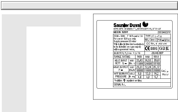
1.2 Data
See Table 1
All dimensions are given in millimetres (except as noted).
The Seasonal Efficiency Domestic Boilers UK (SEDBUK) is Xeon 120ff = 78.1.
The value is used in the UK Government’s Standard Assessment Procedure (SAP) for energy rating of dwellings. The test data from which it has been calculated have been certified by B.S.I.
9 |
2000225135A |
1 General Data
|
DATA TABLE 1. |
|
|
|
|
TOTAL DRY |
|
|
WEIGHT |
71.0 kg |
|
(Including |
(157 lb) |
|
Terminal) |
|
|
|
|
|
* |
63.3 kg |
|
LIFT WEIGHT |
(140 lb) |
|
|
||
|
|
|
WATER |
3.8 litres |
|
CONTENT |
(0.84 gal) |
|
|
|
|
GAS |
Rc 1/2 in. |
|
CONNECTION |
|
|
|
|
|
ELECTRICITY |
97W |
|
RATING |
Internal fuse F1 & F2 (F1A) |
|
|
|
|
WATER |
2x28mm copper pipes from |
|
CONNECTION |
top of case |
|
|
|
|
ELECTRICITY |
230V~50Hz, fused 3A |
|
SUPPLY |
||
|
||
|
|
|
DATA LABEL |
Bottom right hand side of case |
|
|
|
11855 |
11856 |
|
Diagram 1.2 |
1.3 Range Rating
This boiler is range rated and may be adjusted to suit individual system requirements.
Diagram 1.2 gives the ratings and settings.
*Note: Lift weight is with Flue Elbow, Controls Cover and Front Cover removed.
1.7 Water System
This boiler may be fitted to an open vented or sealed water system.
1.8 Safety Valve
A safety valve need not be fitted to an open vented system.
1.4 B.S.I. Certification
This boiler is certificated to the current issue of BS6332 Part 1, invoking the current issue of BS5258 Part 1 for performance and safety. It is, therefore, important that no alteration is made to this boiler without permission, in writing, from Hepworth Heating Ltd.
Any alteration that is not approved by Hepworth Heating Ltd., could invalidate the B.S.I. Certification of the boiler, warranty and could also infringe the current issue of the Statutory Requirements.
1.5 Gas Supply
The gas installation shall be in accordance with the relevant standards.
In GB this is BS6891.
In IE this is the current edition of I.S.813 "Domestic Gas Installations".
The supply from the governed meter must be of adequate size to provide a steady inlet working pressure of 20mbar (8in wg) at the boiler.
On completion test the gas installation for soundness using the pressure drop method and suitable leak detection fluid, purge in accordance with the above standard.
1.6 Contents of Packaging
The boiler is delivered in one pack, refer to Section 4.1 for contents.
Refer to Section 4.2 to check that the flue terminal assembly supplied is suitable.
2000225135A |
10 |
1 General Data
1.9 Location
This boiler is not suitable for outdoor installation.
This boiler may be installed in any room, although particular attention is drawn to the installation of a boiler in a room containing a bath or shower where reference must be made to the relevant requirements.
In GB this is the current I.E.E. WIRING REGULATIONS and BUILDING REGULATIONS.
In IE reference should be made to the current edition of I.S.813 "Domestic Gas Installations" and the current ETCI rules.
Any electrical switch or boiler control utilising mains electricity should be placed so that it cannot be touched by a person using the bath or shower. The electrical provisions of the Building Standards (Scotland) apply to such installations in Scotland.
The boiler must be mounted on a flat wall which is sufficiently robust to take its total weight.
The boiler may be fitted to a wall made of combustible material.
1.10 Boiler Clearances
Refer to diagram 1.3.
The boiler must be positioned so that at least the minimum operational and servicing clearances are provided.
Additional clearances may be required for installation.
If fixtures are positioned next to the boiler they should be made removable for access to pipework.
Sufficient clearance must be left in front of the boiler for servicing.
1.11 Room Ventilation
The boiler is room sealed and does not require the room or space containing it to have permanent airvents.
1.12 Boilers in a Compartment
Where the installation of the boiler will be in an unusual position, special requirements are needed, the current issue of BS6798 gives detailed guidance on these requirements.
A compartment used to enclose the boiler must be designed and constructed specifically for this purpose. An existing cupboard or compartment modified for the purpose may be used. Details of essential requirements for cupboard or compartment design are given in the current issue of BS6798.
The doorway opening should be of sufficient size to allow for easy removal of the boiler.
Where the boiler is fitted in a cupboard or compartment, permanent high and low level ventilation must be provided. The minimum ventilation areas are given in Table 3.
1.13 Timber Frame Building
If the boiler is to be installed in a timber frame building it should be fitted in accordance with the Institute of Gas Engineers document IGE/UP/7/1998. If in doubt seek advice from the local gas undertaking or Hepworth Heating Ltd.
1.14 Heating System Controls
The heating system should have installed: a programmer and room thermostat controlling the boiler.
11854
6mm
 6mm
6mm
PLAN
VIEW
500mm
Additional clearances may be required for installation
160mm |
6mm |
|
6mm |
6mm |
FRONT
VIEW
65mm
MINIMUM CLEARANCES FROM WALLS CEILING, FLOOR, CUPBOARD, WORKTOPS, AND INFLAMMABLE MATERIALS
Diagram 1.3
TABLE 3. COMPARTMENT AIR VENTS |
11862 |
||||
|
|||||
|
|
|
|
|
|
VENTILATION |
HIGH LEVEL |
LOW LEVEL |
|
||
REQUIREMENTS |
VENT AREA |
VENT AREA |
|
||
|
|
|
|
|
|
|
cm2 |
in2 |
cm2 |
in2 |
|
VENTILATION |
|
|
|
|
|
|
|
|
|
|
|
FROM |
|
|
|
|
|
ROOM |
396 |
61.5 |
396 |
61.5 |
|
OR SPACE |
|
|
|
|
|
|
|
|
|
|
|
VENTILATION |
|
|
|
|
|
FROM |
198 |
30.5 |
198 |
30.5 |
|
OUTSIDE |
|
||||
|
|
|
|
|
|
|
|
|
|
|
|
Note: For further information, see the current issue of the Building Regulations, approved document L1 (in the UK) and the references:
1)GIL 59, 2000: Central heating system specification (CheSS) and
2)GPG 302, 2001: Controls for domestic central heating system and hot water. BRESCU.
11 |
2000225135A |

2 Flue Terminal
2.1 Terminal Position
The minimum acceptable siting dimensions for the terminal from obstructions, other terminals and ventilation openings are shown in diagram 2.1. For Ireland the minimum distances for flue terminal positioning must be those detailed in I.S.813 "Domestic Gas Installations".
The terminal must be exposed to the external air, the position allowing free passage of air across it at all times.
Car ports or similar extensions of a roof only, or a roof and one wall, require special consideration with respect to any openings, doors, vents or windows under the roof. Care is required to protect the roof if it is made of plastic sheeting. If the car port consists of a roof and two or more walls, seek advice from the local gas company before installing the boiler.
If the terminal is fitted within 600mm below plastic guttering or painted soffit an aluminium shield 1500mm long should be fitted immediately beneath the guttering or eaves. If the terminal is fitted within 450mm below painted eaves or a painted gutter, an aluminium shield 750mm long should be fitted immediately beneath the guttering or eaves.
2.2 Terminal Guard
A terminal guard is required if persons could come into contact with the terminal or the terminal could be subject to damage.
If a terminal guard is required, it must be positioned to provide a minimum of 50mm clearance from any part of the terminal and be central over the terminal.
A suitable guard, reference Type K3, can be obtained from:
Tower Flue Components Ltd
Morley Road
Tonbridge
Kent
TN9 1RA
0103M
A |
C |
|
|
|
B,C |
B,C |
K |
|
|
|
|
|
A |
|
G |
K |
L L |
|
|
|||
|
M |
K |
||
F |
|
F |
||
|
F |
|
||
G |
E |
A |
|
|
G |
|
G |
||
|
|
G |
|
|
Under Car Port etc.
D |
J |
F |
K |
H,I |
MINIMUM SITING DIMENSIONS FOR |
MINIMUM |
||
FANNED FLUE TERMINALS POSITION |
SPACING in mm |
||
|
|
|
|
A |
DIRECTLY BELOW, ABOVE OR HORIZONTALLY |
|
|
|
TO AN OPENING, AIR BRICK, OPENING WINDOWS, |
||
|
AIR VENT OR ANY OTHER |
|
|
|
VENTILATION OPENING. |
|
300 |
B |
BELOW GUTTER, DRAIN/SOIL PIPE |
|
75 |
C |
BELOW EAVES |
|
200 |
D |
BELOW A BALCONY OR CAR PORT |
|
200 |
E |
FROM VERTICAL DRAIN PIPES AND SOIL PIPES |
25 |
|
F |
FROM INTERNAL/EXTERNAL CORNERS |
|
|
|
OR TO A BOUNDARY ALONGSIDE |
|
|
|
THE TERMINAL |
|
25 |
G |
ABOVE ADJACENT GROUND OR BALCONY LEVEL 25 |
||
H |
FROM A SURFACE FACING THE TERMINAL |
600 |
|
I |
FACING TERMINALS |
|
1200 |
J |
FROM OPENING (DOOR/WINDOW) IN |
|
|
|
CAR PORT INTO DWELLING |
|
1200 |
K |
VERTICAL FROM A TERMINAL |
|
1500 |
L |
HORIZONTALLY FROM A TERMINAL |
|
300 |
M |
FROM INTERNAL CORNERS |
|
25 |
|
|
|
4307 |
Diagram 2.1
2000225135A |
12 |
 Loading...