

Samsung SNP-6320RH User Manual

NETWORK CAMERA
User Manual
SNP-6320RH

Network Camera
User Manual
Copyright
©2015 Samsung Techwin Co., Ltd. All rights reserved.
Trademark
The name of thi s product is the reg istered tradema rk of Samsung Techwin C o., Ltd.
Other trad emarks mention ed in this manual are th e registered trad emark of their resp ective company.
Restriction
Samsung Techwi n Co., Ltd shall reser ve the copyrigh t of this document. U nder no circumst ances, this docu ment shall
be reproduced, distributed or changed, partially or wholly, without formal authorization of Samsung Techwin.
Disclaimer
Samsung Techwi n makes the best to ver ify the integri ty and correct ness of the conten ts in this document , but no
formal guar antee shall be provi ded. Use of this do cument and the subse quent results sha ll be entirely on the u ser’s own
responsib ility. Samsung Techwi n reserves the ri ght to change the con tents of this docum ent without prio r notice.
Design and specifications are subject to change without prior notice.
The initi al administra tor ID is “admin” a nd the passwor d should be set wh en logging in for t he first time.
Please ch ange your pass word every thr ee months to saf ely protect p ersonal inf ormation and t o prevent
the damage of the information theft.
Please, t ake note that it ’s a user’s respo nsibility fo r the securit y and any other pr oblems cause d by
mismanaging a password.
is the regist ered logo of Samsun g Techwin Co., Ltd.

overview
IMPORTANT SAFETY INSTRUCTIONS
1. Read these instructions.
2. Keep these instructions.
3. Heed all warnings.
4. Follow all instructions.
5. Do not use this apparatus near water.
6. Clean only with dry cloth.
7. Do not block any ventilation openings, Install in accordance with the manufacturer’s
instructions.
8. Do not install near any heat sources such as radiators, heat registers, stoves, or other
apparatus (including amplifiers) that produce heat.
9. Do not defeat the safety purpose of the polarized or grounding-type plug. A polarized
plug has two blades with one wider than the other. A grounding type plug has two
blades and a third grounding prong. The wide blade or the third prong are provided for
your safety. If the provided plug does not fit into your outlet, consult an electrician for
replacement of the obsolete outlet.
10. Protect the power cord from being walked on or pinched particularly at plugs,
convenience receptacles, and the point where they exit from the apparatus.
11. Only use attachments/ accessories specified by the manufacturer.
12. Use only with the cart, stand, tripod, bracket, or table specified by
the manufacturer, or sold with the apparatus. When a cart is used,
use caution when moving the cart/apparatus combination to avoid
injury from tip-over.
13. Unplug this apparatus during lighting storms or when unused for
long periods of time.
14. Refer all servicing to qualified service personnel. Servicing is required when the
apparatus has been damaged in any way, such as power-supply cord or plug is
damaged, liquid has been spilled or objects have fallen into the apparatus, the apparatus
has been exposed to rain or moisture, does not operate normally, or has been dropped.
15. This product is intended to be supplied by Power Unit marked “Class 2” or “LPS” and
rated 24 Vac, 6 A.
● OVERVIEW
English _3
overview
WARNING
TO REDUCE THE RISK OF FIRE OR ELECTRIC SHOCK, DO NOT EXPOSE
THIS PRODUCT TO RAIN OR MOISTURE. DO NOT INSERT ANY METALLIC
OBJECT THROUGH THE VENTILATION GRILLS OR OTHER OPENNINGS
ON THE EQUIPMENT.
Apparatus shall not be exposed to dripping or splashing and that no objects
filled with liquids, such as vases, shall be placed on the apparatus.
To prevent injury, this apparatus must be securely attached to the Wall/ceiling
in accordance with the installation instructions.
CAUTION
CAUTION
RISK OF ELECTRIC SHOCK.
DO NOT OPEN
CAUTION
REFER SERVICING TO QUALIFIED SERVICE PERSONNEL.
: TO REDUCE THE RISK OF ELECTRIC SHOCK.
DO NOT REMOVE COVER (OR BACK).
NO USER SERVICEABLE PARTS INSIDE.
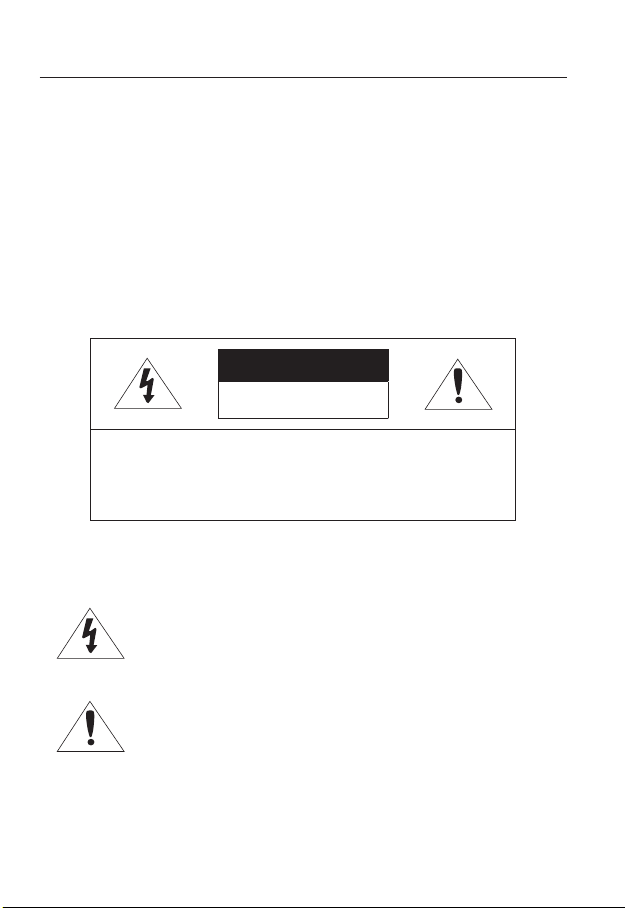
EXPLANATION OF GRAPHICAL SYMBOLS
The lightning flash with arrowhead symbol, within an
equilateral triangle, is intended to alert the user to the
presence of “dangerous voltage” within the product’s
enclosure that may be of sufficient magnitude to constitute a
risk of electric shock to persons.
The exclamation point within an equilateral triangle is intended
to alert the user to the presence of important operating
and maintenance (servicing) instructions in the literature
accompanying the product.
4_ overview

Battery
Batteries(battery pack or batteries installed) shall not be exposed to excessive
heat such as sunshine, fire or the like.
CAUTION
Risk of explosion if battery is replaced by an incorrect type.
Dispose of used batteries according to the instructions.
These servicing instructions are for use by qualified service personnel only.
To reduce the risk of electric shock do not perform any servicing other than
that contained in the operating instructions unless you are qualified to do so.
The CVBS out terminal of the product is provided for easier installation, and is
not recommended for monitoring purposes.
Please use the input power with just one camera and other devices must not
be connected.
The ITE is to be connected only to PoE networks without routing to the
outside plant.
● OVERVIEW
English _5

overview
Please read the following recommend safety precautions carefully.
yDo not place this apparatus on an uneven surface.
yDo not place this apparatus near conductive material.
yDo not attempt to service this apparatus yourself.
yDo not install near any magnetic sources.
yDo not block any ventilation openings.
yDo not place heavy items on the product.
yDo not expose the camera to radioactivity.
User’s Manual is a guidance book for how to use the products.
The meaning of the symbols are shown below.
yReference : In case of providing information for helping of product’s usages
yNotice : If there’s any possibility to occur any damages for the goods and
human caused by not following the instruction
Please read this manual for the safety before using of goods and keep it in
the safe place.
6_ overview

CONTENTS
OVERVIEW
3
INSTALLATION &
CONNECTION
16
NETWORK CONNECTION
AND SETUP
31
3 Important Safety Instructions
9 Product Features
10 Recomended PC Specifications
11 Recomended SD/SDHC/SDXC
Memory Card Specifications
11 NAS recommended specs
12 What’s Included
13 At a Glance
18 Connecting with other Device
20 Installation
28 Inserting/Removing a SD Memory
Card
30 Memory Card Information
(Not Included)
31 Connecting the Camera Directly
to Local Area Networking
32 Connecting the Camera Directly
to a DHCP Based DSL/Cable
Modem
33 Connecting the Camera Directly
to a PPPoE Modem
34 Connecting the Camera to a
Broadband Router with the
PPPoE/Cable Modem
35 Buttons used in IP Installer
36 Static IP Setup
40 Dynamic IP Setup
41
Port Range Forward (Port Mapping)
Setup
43 Connecting to the Camera from a
Shared Local PC
43 Connecting to the Camera from a
Remote PC via the Internet
● OVERVIEW
English _7

overview
WEB VIEWER
44
SETUP SCREEN
61
APPENDIX
137
44 Connecting to the Camera
45 Password setting
46 Login
47 Installing STW WebViewer Plugin
49 Using the Live Screen
54 Playing the recorded video
61 Setup
61 Basic Setup
71 PTZ setup
84 Video & Audio setup
98 Network Setup
107 Event Setup
112 NAS (Network Attached Storage)
guide
130 System Setup
136 Viewing profile information
137 DIP Switch Setting
139 Camera Wiring
140 Specification
145 Product Overview
146 Troubleshooting
148 Open Source Announcement
8_ overview

PRODUCT FEATURES
• Full HD Video Quality
• Multi-Streaming
This network camera can display videos in different resolutions and qualities
simultaneously using different CODECs.
• Web Browser-based Monitoring
Using the Internet web browser to display the image in a local network environment.
• Alarm
If an event occurs, the camera sends the relevant videos to the e-mail address or the FTP
server registered by the user, saves them in an SD card or NAS, or sends the signal to the
alarm output terminal.
• Tampering Detection
Detects tempering attempts on video monitoring.
• Motion Detection
Detects motion from the camera’s video input.
• Intelligent Video Analysis
Analyzes video to detect logical events of specified conditions from the camera’s video
input.
• Face Detection
Detects faces from the camera’s video input.
• Audio Detection
Detects sound louder than a certain level specified by user.
• Auto Detection of Disconnected Network
Detects network disconnection before triggering an event.
• ONVIF Compliance
This product supports ONVIF Profile-S.
For more information, refer to www.onvif.org.
● OVERVIEW
English _9

overview
RECOMENDED PC SPECIFICATIONS
• CPU : Intel Core 2 Duo 2.6 GHz or higher (for using 1920x1080 30 fps)
Intel Core i7 2.8 GHz or higher (for using 1920x1080 60 fps)
Web Plug-in is optimized to SSE 4.1 Instruction Set.
`
• Resolution : 1280X1024 pixels or higher (32 bit color)
• RAM : 2GB or higher
• Supported OS : Windows XP / VISTA / 7 / 8, MAC OS X 10.7
• Supported Browser : Microsoft Internet Explorer (Ver. 8~11),
Mozilla Firefox (Ver. 9~19), Google Chrome (Ver. 15~25),
Apple Safari (Ver. 6.0.2(Mac OS X 10.8, 10.7 only), 5.1.7) *Mac OS X Only
Windows 8 is supported only in the Desktop mode.
`
Neither a beta test version unlike the version released in the company website nor the developer version will
`
be supported.
It is recommended to connect to IPv6 in Windows 7.
`
The camera does not support Internet Explorer Compatability View settings.
`
For Mac OS X, only the Safari browser is supported.
`
• Video Memory : 256MB or higher
If the driver of the video graphic adapter is not installed properly or is not the latest version, the
`
J
video may not be played properly.
For a multi-monitoring system involving at least 2 monitors, the playback performance can be
`
deteriorated depending on the system.
It is advisable to use Intel Core 2 Duo 2.93GHz or higher in a multi-browser environment.
`
10_ overview

RECOMENDED SD/SDHC/SDXC MEMORY CARD
SPECIFICATIONS
• Recommended capacity : 4GB ~ 64GB
• For your camera, we recommend you use a memory card from the following
manufacturers:
SD/SDHC/SDXC Memory Card : Sandisk, Transcend
• For the framerate below 30 fps, it is recommended to use the specification memory card
of Class 6 or higher.
• For the framerate over 31 fps, it is recommended to use the specification memory card of
Class 10 UHS or higher.
NAS RECOMMENDED SPECS
• Recommended capacity : 200GB or higher is recommended.
• Simultaneous access : One unit of NAS can accept a maximum of sixteen camera
accesses.
• For this camera, you are recommended to use a NAS with the following manufacturer’s
specs.
Recommended products Available sizes
Netgear NAS A maximum of 16 cameras can access simultaneously.
Synology NAS A maximum of 16 cameras can access simultaneously.
When you use Netgear’s NAS equipment, do not allocate the capacity for use.
`
J
If you use NAS equipment for purposes other than video saving, the number of accessible
`
cameras may be reduced.
● OVERVIEW
English _11

overview
WHAT’S INCLUDED
Please check if your camera and accessories are all included in the product package.
Appearance Item Name Quantity Description
Main Body 1
12_ overview
Instruction book,
Installer S/W CD
Quick Guide
(Optional)
Warranty card
(Optional)
Cable for the testing monitor 1
Hexagon screw 3
L Wrench 1
Installation base 1 Bracket for mounting outdoors
Waterproofing accessory 1 Install and use where there is high humidity.
1
1
1
Used to test the camera connection to a
portable display device
Used for attaching the installation base to
the camera
Used for fixing the installation base after
attaching it to the camera
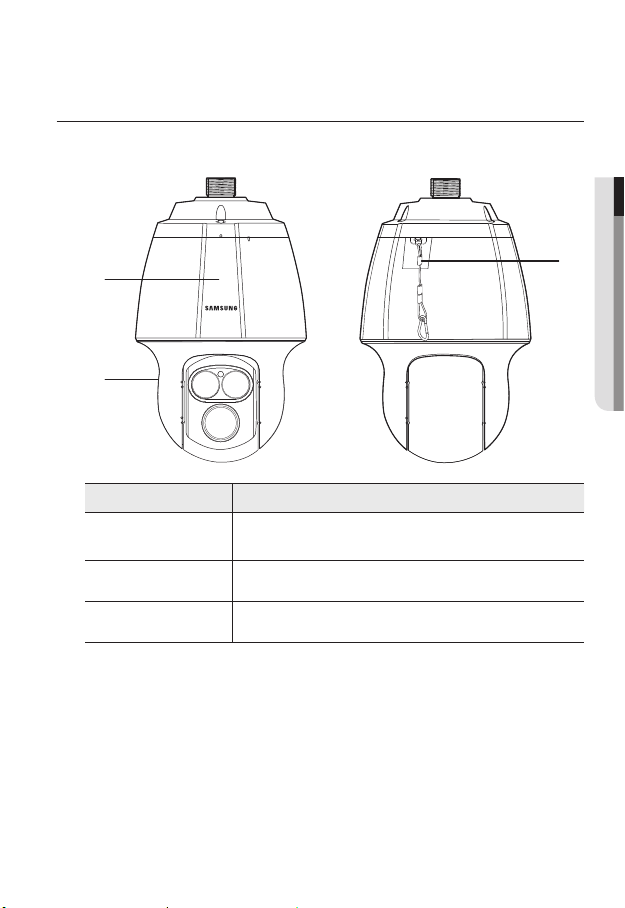
AT A GLANCE
Appearance
● OVERVIEW
a
b
Item Description
Main unit
a
Shield cover Shield cover for the lens and unit protection.
b
Safety Cable The cable prevents the product from dropping during installation.
c
Protects the internal PTZ mechanism from the direct sunlight, rain or
external impact.
c
English _13

overview
Inside
c
d
e
Item Description
SD Memory Card
a
Compartment
Initialization Switch
b
a b
Compartment for the SD memory card.
MRefer to <Inserting/Removing a SD Memory Card> for the SD
memory card insertion position. (page 28)
The camera is reset to factory initialization condition.
For details, refer to <Upgrade / Reboot>. (page 131)
M
`
Refer to <Inserting/Removing a SD Memory Card> for the
`
switch position. (page 28)
Illumination Sensor Detects incoming light to control the IR LED.
c
IR LED These infrared LED’s are controlled by the illumination sensor.
d
Lens Lens for the camera.
e
14_ overview

Bottom View of Installation
Inner View of Installation Base
Base
g
fed h
ON DIP
Video Out
Power
AC 22~26V
D+ D- TXD+
D+ D- TXD+
AUDIO_OUTAUDIO_IN
TXD-
TXD GND
GND
A.COM
A.COM
A.NO
A.NO
AXICOM
IMO3
5VDC
AXICOM
AUDIO_OUTAUDIO_IN
1143Н
1143Н
AXICOM
IMO3
5VDC
AXICOM
IMO3
5VDC
AXICOM
AXICOM
IMO3
5VDC
IMO3
5VDC
Alarm2 ONAlarm1 ON
Alarm2 ON
Alarm1 ON
a b c
Item Description
Communications
a
and AUX Ports
Audio Input Port Used to connect the audio input cable. (Mono jack plug is not supported.)
b
Audio Output Port Used to connect the audio output cable. (Mono jack plug is not supported.)
c
Video Out Port Analog video output port. (for installation)
d
Communications
e
Setup Switch
Network
f
Connections
Power Port Used to connect the power.
g
Used for RS-485/422 communications.
Communication method and terminal value are set up.
Used to connect the LAN cable. (10/100Mbps supported)
● OVERVIEW
2N.C
2N.0
COM2
1N.C
1N.0
COM1
GND
IN4
IN3
GND
IN2
IN1 IN2 GND IN3 IN4 GND 1C0M 1.N0 1.NC 2C0M 2.N0 2.NC
IN1 IN2 GND IN3 IN4 GND 1C0M 1.N0 1.NC 2C0M 2.N0 2.NC
IN1
1143Н
Alarm
IMO3
5VDC
Alarm I/O Port Used to connect the alarm I/O cable.
h
English _15

installation & connection
`Camera Wiring Interface Board
For the camera wiring, please refer to the picture below.
Power Supply
AC24V 6A
Video
Output
ON DIP
Video Out
D+ D- TXD+
D+ D- TXD+
TXD-
TXD GND
GND
A.COM
A.COM
A.NO
A.NO
1143Н
1143Н
AXICOM
IMO3
AXICOM
IMO3
5VDC
AXICOM
IMO3
AXICOM
IMO3
5VDC
Alarm1 ON
ETHERNET
Communications and AUX
D+ D- TXD+ TXD- GND
Refer to Control Signal
Connection Diagram
5VDC
5VDC
Power
AC 22~26V
AUDIO_OUTAUDIO_IN
AUDIO_OUTAUDIO_IN
AXICOM
IMO3
5VDC
AXICOM
Alarm2 ONAlarm1 ON
Alarm2 ON
Audio IN
1143Н
IMO3
5VDC
A.COM
A.NO
Alarm
2N.C
2N.0
COM2
1N.C
1N.0
COM1
GND
IN4
IN3
GND
IN2
IN1 IN2 GND IN3 IN4 GND 1C0M 1.N0 1.NC 2C0M 2.N0 2.NC
IN1 IN2 GND IN3 IN4 GND 1C0M 1.N0 1.NC 2C0M 2.N0 2.NC
IN1
Alarm
Audio OUT
Power Input
Ground
Alarm output
Alarm Input
AUX Output
16_ installation & connection

The maximum power capacity of the alarm and AUX outputs is 30VDC/2A, 125VAC/0.5A, and
`
J
250VAC/0.25A.
When connecting alarm input and output cables, be sure to connect one cable to each terminal
`
respectively.
To connect products over the camera’s capacity, please use an additional relay device.
`
Connecting the power connector and GND incorrectly to the alarm out port may lead to fire and
`
damage the camera.
● INSTALLATION & CONNECTION
English _17

installation & connection
CONNECTING WITH OTHER DEVICE
Preparing Adapter and Cable
Connect the camera to the power adaptor. Then, plug the power cord of the adaptor to the wall
`
J
outlet.
D+ D- TXD+
TXD-
GND
A.COM A.NO
D+ D- TXD+
TXD-
GND
A.COM A.NO
AXICOM
IMO3
AXICOM
5VDC
IMO3
5VDC
Alarm1 ON
AXICOM
AXICOM
IMO3
IMO3
5VDC
5VDC
Alarm2 ONAlarm1 ON
AXICOM
Alarm2 ON
IMO3
AXICOM
5VDC
IMO3
5VDC
Check out the rated voltage and current before making connections.
ON DIP
1143Н
Video Out
1143Н
AC 22~26V
AUDIO_OUTAUDIO_IN
AUDIO_OUTAUDIO_IN
Power
1143Н
IN1 IN2 GND IN3 IN4 GND 1C0M 1.N0 1.NC 2C0M 2.N0 2.NC
IN1 IN2 GND IN3 IN4 GND 1C0M 1.N0 1.NC 2C0M 2.N0 2.NC
Alarm
COM2
COM1
1N.C
2N.C
GND
GND
1N.0
2N.0
IN4
IN3
IN2
IN1
Rated Power Allowable Input Voltage Current Consumption
AC 24V AC 22V ~ 26V 6 A
The product cannot be used at -50°C or below ambient temperature.
`
J
The product may not be defrosted depending on the installation area at -50°C.
`
Leave the product always turned on to maintain the internal temperature of -10°C or higher.
`
After the product is left alone under a low temperature environment, it will take up to 3 hours to
`
normally operate.
The zooming speed of the IR dimmer may slow down at -40°C or lower environment.
`
If the product is turned on after being exposed to -40°C or below environment for some time,
`
reset the time.
18_ installation & connection
Electrical Resistance of Copper Wire at [20°C (68°F)]
Copper Wire Gauge (AWG) #24(0.22mm2) #22(0.33mm2) #20(0.52mm2) #18(0.83mm2)
Resistance (Ω/m) 0.078 0.050 0.030 0.018
Drop Voltage (V/m) 0.028 0.018 0.011 0.006
Recommended Distance (m) Less than 20 Less than 30 Less than 30 Less than 30
As shown in the table above, you may encounter a voltage-sag depending on the wire length.
`
If you use an excessively long wire for camera connection, the camera may not work properly.
Camera Operating Voltage: AC 24V±10%
-
Voltage drop measurements on the chart above may vary depending on the type and manufacture of
-
the copper cable.
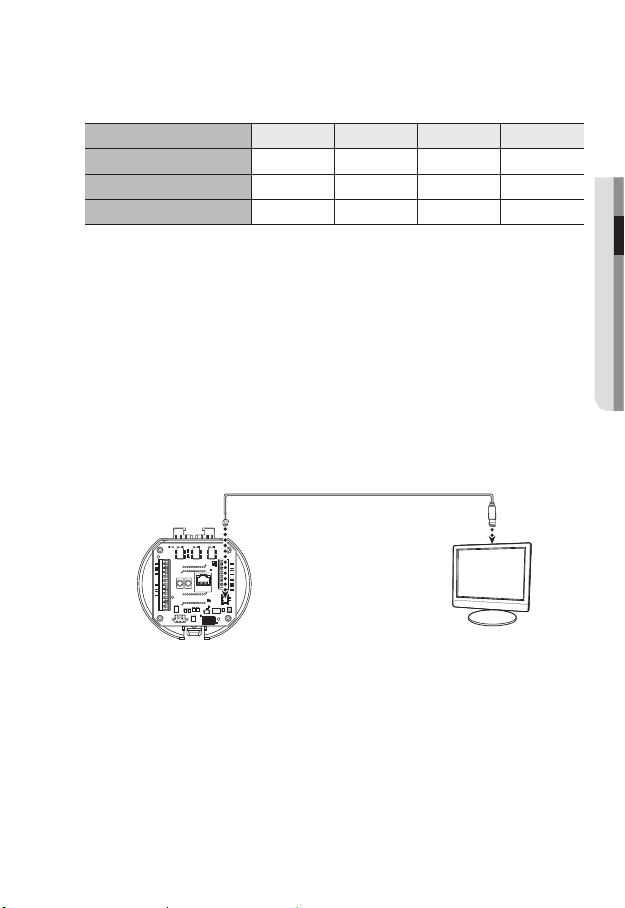
Ethernet Connection
Connect the Ethernet cable to the local network or to the Internet.
Connecting the installation monitor
Connect the cable to the camera’s rear video output terminal and the installation monitor’s
video input terminal.
Alarm2 ONAlarm1 ON
Alarm2 ON
Alarm1 ON
AXICOM
IMO3
5VDC
AXICOM
IMO3
5VDC
AXICOM
IMO3
5VDC
AXICOM
IMO3
5VDC
AXICOM
IMO3
5VDC
AXICOM
IMO3
5VDC
Alarm
1143Н
1143Н
1143Н
IN1
IN1 IN2 GND IN3 IN4 GND 1C0M 1.N0 1.NC 2C0M 2.N0 2.NC
IN1 IN2 GND IN3 IN4 GND 1C0M 1.N0 1.NC 2C0M 2.N0 2.NC
IN2
GND
IN3
IN4
GND
COM1
1N.0
1N.C
COM2
2N.0
2N.C
The wiring varies depending on your monitor type and peripheral devices; please refer to the user manual
`
for each device.
Please make sure the monitor and camera are turned off when connecting them.
`
A.NO
A.NO
A.COM
A.COM
GND
GND
TXD-
TXD-
AUDIO_OUTAUDIO_IN
AUDIO_OUTAUDIO_IN
D+ D- TXD+
D+ D- TXD+
AC 22~26V
Power
Video Out
ON DIP
Monitor
● INSTALLATION & CONNECTION
English _19

installation & connection
This product is a network camera that transfers video over a network; the video output terminal is
`
J
used to set the imaging range of the camera at installation.
Using the terminal for monitoring purposes may cause problems such as degradation in video
`
quality.
It is not suitable for 24-hour monitoring using professional CRT monitors or TFT/LCD portable
`
monitors.
Use the network transfer screen for 24-hour monitoring and storage.
`
INSTALLATION
Preparing & Installing Camera Bracket
For installation guidelines for brackets and housings, refer to the installation manual that is
enclosed with the bracket or housing.
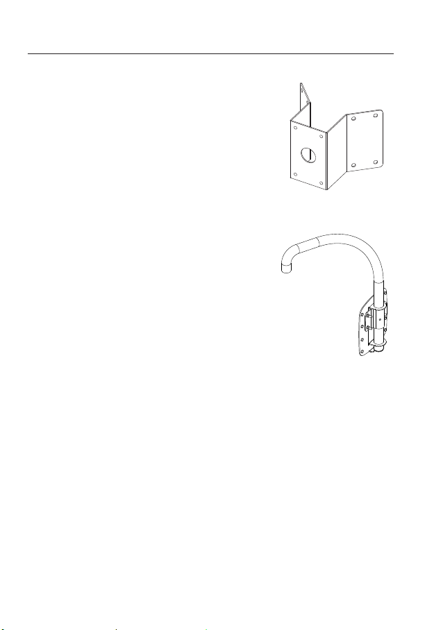
`Available Bracket Models
Model Item
SBP-300WM1
SBP-300WM
SBP-300CM Ceiling Mount
SBP-300LM Parapet Mount
SBP-300KM Corner Mount
SBP-300PM Pole Mount
See “Optional Accessories for Installation” for the appearance of each bracket (unbundled).
`
M
(page 24)
Wall Mount
20_ installation & connection
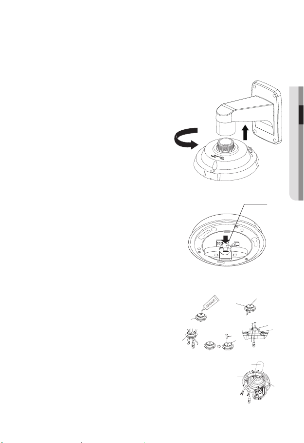
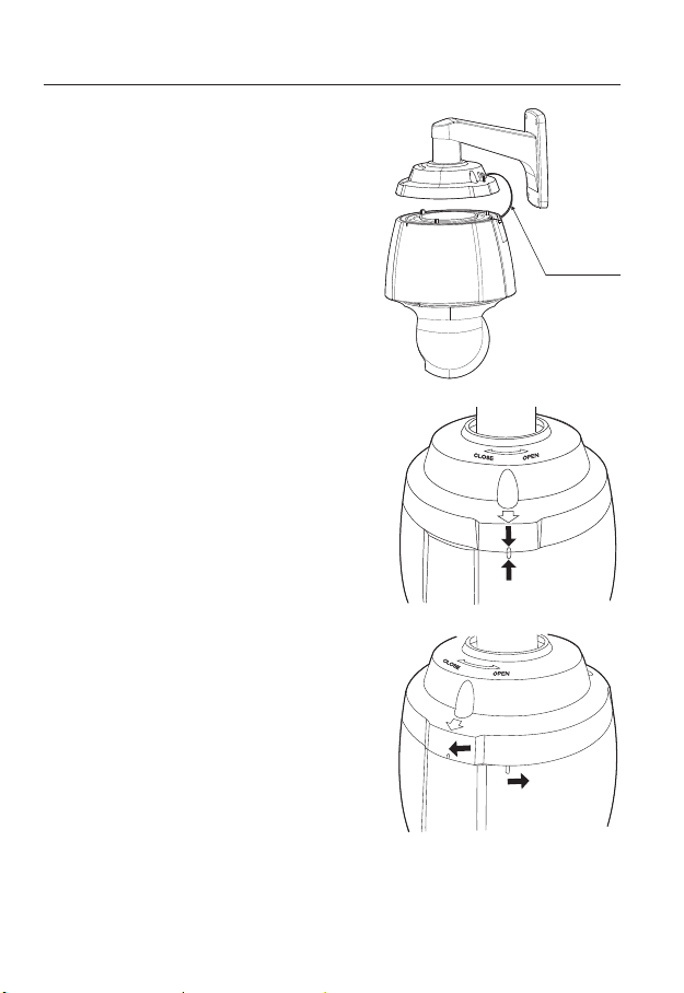
Installing by wall mount
하우징
또는 마운트
BUSH
인터페이스
`Fix the installation base with the bracket
1. Fix the base with the bracket by turning it
clockwise.
● INSTALLATION & CONNECTION
2. As shown in the picture below, gently press
and lift up the handle of the hinged door on the
bottom of the installation base. Please refer to
the “Camera Wiring Interface Board” on page
16, connect the wires.
Do not connect the camera to a power outlet until the
`
J
installation is complete. Supplying power while the
installation is in progress may cause fire or damage
the product.
Check cable connection method and install.
M
Note that BUSHINGs are provided for outdoor
`
installations where exposed to a moisture
condition through the PIPE or MOUNT, install
the HOUSING using the BUSHING to prevent
moisture entering.
Apply grease of proper dose on the BUSHING
-
before assembling, and run cables through each hole of the
bushings. Use PINS to stop up empty holes having no cable
running.
Assemble the BUSHING to the top side of HOUSING’s inside
-
as shown in the diagram below. At the moment, apply pressure
evenly on the BUSHING to secure it tightly to the HOUSING as
shown in the diagram.
Knob
POE+ 또는 이더넷 케이블
POE+ or Ethernet cable
POWER
POWER (AC24V)
(AC24V)
기타 케이블
인터페이스
INTERFACE
핀
PIN
BUSH
BUSH
HOUSING OR
ETC CABLE
하우징
또는 마운트
MOUNT
BUSH
BUSH
하우징
HOUSING
BUSH
BUSH
BUSH
BUSH
BUSH
BUSH
English _21
installation & connection
3. Connect the camera safety wire to the
installation base.
4. Assemble Camera and Installation Base
Assemble the installation base and camera by
matching the installation direction guides.
5. Attach Camera
Turn the camera frame counterclockwise until
the protrusions on the camera frame and
installation base become matched perfectly.
Safety Cable
22_ installation & connection

6. Secure Camera and Installation Base
As shown in the picture below, secure the
installation base and camera using 3 hexagon
screws.
Notes for Waterproofing
This model is an integrated housing product for outdoor installation.
`When combining the main body and the wall mount for installation on the
wall
1. Install the wall mount on the vertical
wall. When it is installed on an inclined
wall, moisture may permeate into the
main body through the external cable.
2. Wrap the screw part of the housing with
a sufficient amount of Teflon tape for
assembly.
3. Please make sure that the gasket is
not disassembled from the shield cover
when the shield cover is separated and
mounted on the housing body.
4. Install the wall mount adapter for
waterproofing, and apply the silicon
sealant between and around the wall
and wall mount for sealing.
Take particular caution to ensure that there
`
J
is proper sealing if the installed side is not
flat.
Silicon
sealant
Wall mount
Screw
unit
Concrete wall
Teflon tape
Shield gasket
● INSTALLATION & CONNECTION
English _23

installation & connection
`When combining the main body and the ceiling mounting adaptor for
installation on the wall
1. Wrap the screw part of the housing
with a sufficient amount of Teflon tape
for assembly.
2. Please make sure that the gasket is
not disassembled from the shield cover
when the shield cover is separated and
mounted on the housing body.
3. Install the ceiling mount adapter for
waterproofing, and apply the silicon
sealant between and around the wall
and ceiling mount for sealing.
Take particular caution to ensure that
`
J
there is proper sealing if the installed side
is not flat.
Ceiling mount
adapter
Ceiling board
Screw
unit
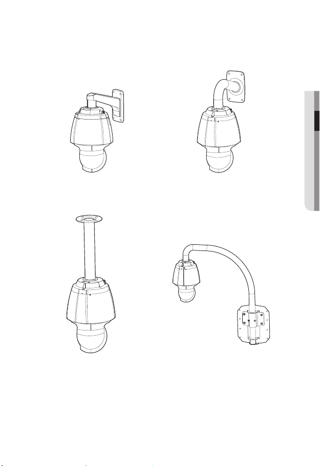
Optional Accessories for Installation
For your easier installation, you can purchase appropriate optional accessories available.
1. If installing the camera on the wall
• Wall mount (SBP-300WM1)
Concrete ceiling
Silicon
sealant
Teflon tape
Shield gasket
24_ installation & connection

• Wall mount (SBP-300WM)
2. If installing the camera on the ceiling
• Ceiling Mount (SBP-300CM)
3. If installing the wall mount (SBP-300WM/SBP-300WM1) on an at least 80mm-long
cylinder
• Pole Mount (SBP-300PM)
● INSTALLATION & CONNECTION
English _25
installation & connection
4. If installing the wall mount (SBP-300WM/SBP-300WM1) on a corner of the wall
• Corner Mount (SBP-300KM)
5. If installing on a building rooftop
• Parapet Mount (SBP-300LM)
26_ installation & connection
`Mount Joint
● INSTALLATION & CONNECTION
Wall mount (SBP-300WM1)
Ceiling Mount (SBP-300CM)
Wall mount (SBP-300WM)
Parapet Mount (SBP-300LM)
English _27

installation & connection
INSERTING/REMOVING A SD MEMORY CARD
Disconnect the power cable from the camera before inserting the SD memory card.
`
J
Tighten the screws when assembling the camera body, shield cover and SD holder bracket to
`
prevent moisture penetration.
When mounting or dismounting an SD memory card, place the main body on the floor first to
`
prevent part loss and falling accident.
Inserting a SD Memory Card
1. Separate with hands the screws in front of and on
the rear of the shield cover.
2. Unfasten four screws by turning them
counterclockwise using a driver to separate the
shield cover.
3. Unfasten two screws on the SD holder bracket by
turning them counterclockwise using the driver.
Do not remove the screws.
`
J
28_ installation & connection
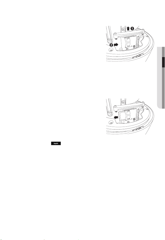
4. Pull up the SD holder bracket and push the SD
memory card to the arrow direction as shown in
the figure.
Do not insert the SD memory card while it’s upside
`
J
down by force. Otherwise, it may damage the SD
memory card.
5. Assemble the camera in the reverse order of
disassembly after the SD memory card is inserted.
Tighten the screws when assembling the camera to prevent moisture penetration.
`
J
Removing a SD Memory Card
Gently press down on the exposed end of the memory
card as shown in the diagram to eject the memory card
from the slot.
Pressing too hard on the SD memory card can cause
`
J
the card to shoot out uncontrollably from the slot when
released.
To turn off the camera or remove the SD memory card,
`
set the card to <Off> in <Storage> menu and press
the [Apply (
If you turn off the camera or remove the SD memory card that contains data from the product, the
`
data may be lost or damaged.
)] button. (page 108)
● INSTALLATION & CONNECTION
English _29

installation & connection
MEMORY CARD INFORMATION (NOT INCLUDED)
What is a memory card?
The memory card is an external data storage device that has been developed to offer an
entirely new way to record and share video, audio, and text data using digital devices.
Selecting a memory card that’s suitable for you
Your camera supports SD/SDHC/SDXC memory cards.
You may, however, experience compatibility issues depending on the model and make of
the memory card.
For your camera, we recommend you use a memory card from the following
manufacturers:
SD/SDHC/SDXC Memory Card : Sandisk, Transcend
Memory cards of 4GB ~ 64GB is recommended for using with this camera.
Playback performance can be affected depending on the speed of memory card, so use
the high-speed memory card.
For the framerate below 30 fps, it is recommended to use the specification memory card of
Class 6 or higher.
For the framerate over 31 fps, it is recommended to use the specification memory card of
Class 10 UHS or higher.
Memory Card Use
SD and SDHC memory cards feature a switch that disables writing data on to the media.
Having this switch to the Lock position will prevent accidental deletion of data stored in the
memory card but at the same time will also prevent you from writing data on to the media.
30_ installation & connection
 Loading...