


X52 manual(ok)(24/11/04) 2004.12.22 9:05 PM Page 3
SAITEK X52 FLIGHT CONTROL SYSTEM - PRODUCT TOUR
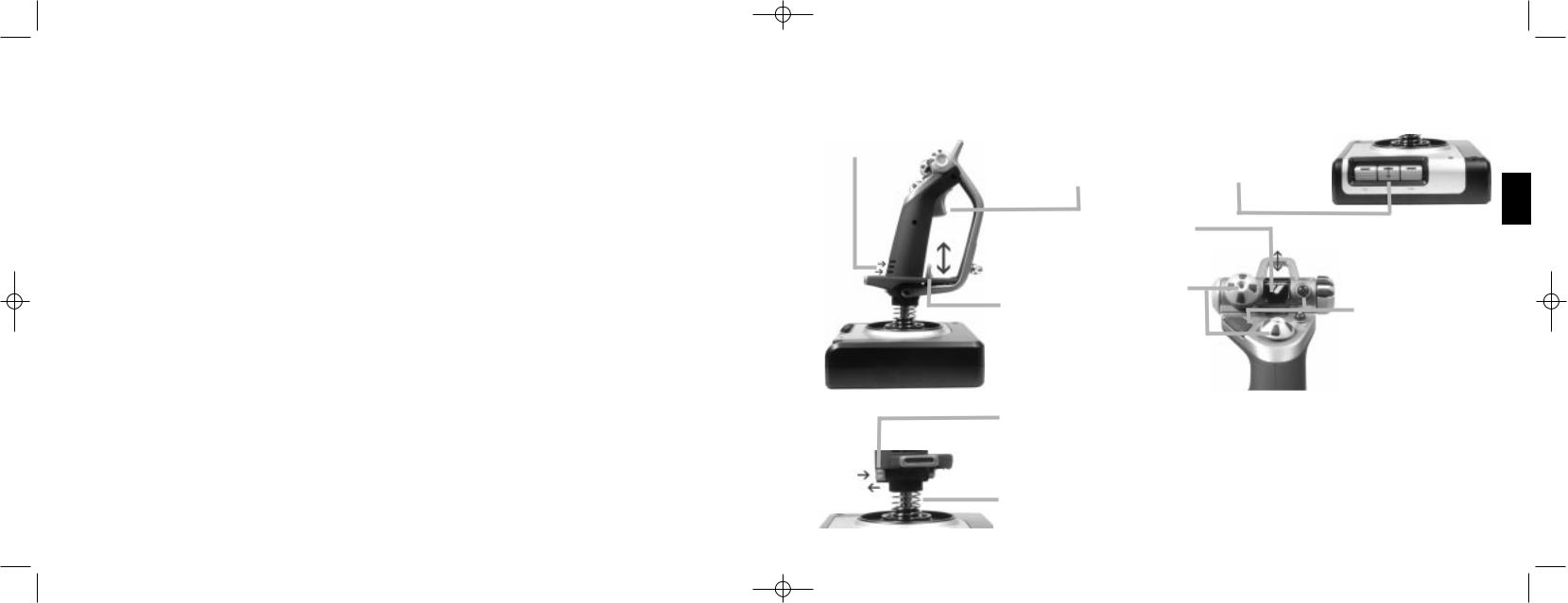
Joystick
5-position adjustment |
|
2-Stage metal trigger |
|
|
3 toggle switches |
||||||||||||||
to suit all hand sizes. |
|
Destroy the enemy with the aid of a |
Spring loaded and conveniently |
||||||||||||||||
|
|
|
|
precise and durable, cool-touch trigger. |
positioned on the base for an |
||||||||||||||
|
|
|
|||||||||||||||||
|
|
|
|
Two-stages can be programmed with |
extra 6 programmable flight |
||||||||||||||
|
|
|
|
separate fire functions. |
|
|
commands. |
||||||||||||
|
|
|
|
|
|
|
|
|
|
|
|
|
|
|
|
|
|
|
|
|
|
|
|
|
|
Missile Launcher |
|
|
|
|
|
|
|
|
|
|
|
|
|
|
|
|
|
|
|
Flip up the spring-loaded |
|
|
|
|
|
|
|||||||
|
|
|
|
|
|
safety cover to activate |
|
|
|
|
|
|
|
|
|
||||
|
|
|
|
|
|
|
|
|
|
|
|||||||||
|
|
|
|
|
|
missile launches. |
|
|
|
|
|
|
|
|
|
|
|
|
|
|
|
|
|
|
|
|
|
|
|
|
|
|
|
|
|
|
|
Mode selector switch |
|
|
|
|
|
Cool-touch |
2 x 8-way hat switches |
|
|
|
|
|
|
|
|
|
|
||||
|
|
|
|
|
|
|
|
|
|
|
|
|
|
3-position rotary switch with tri- |
|||||
|
|
|
|
|
|
|
|
|
|
|
|||||||||
|
|
|
|
metal pinkie |
-1 pre-defined as point |
|
|
|
|
|
|
|
|
|
|
state LED to indicate program |
|||
|
|
|
|
|
|
|
|
|
|
|
|
||||||||
|
|
|
|
switch can be |
of view; select from |
|
|
|
|
|
|
|
|
|
|
|
mode. |
||
|
|
|
|
|
|
|
|
|
|
|
|
|
|
|
|||||
|
|
|
|
assigned shift |
multiple view |
|
|
|
|
|
|
|
|
|
|
3 Fire Buttons |
|||
|
|
|
|
functionality to |
perspectives and |
|
|
|
|
|
|
|
|
|
|
||||
|
|
|
|
|
|
|
|
|
|
|
|
|
|
||||||
|
|
|
|
double up on |
assign frequently used |
|
|
|
|
|
|
|
|
|
|
Backlit buttons |
|||
|
|
|
|
programmable |
commands. |
|
|
|
|
|
|
|
|
|
|
conveniently |
|||
|
|
|
|
commands. |
|
|
|
|
|
|
|
|
|
|
|
|
positioned on |
||
|
|
|
|
|
|
|
|
|
|
|
|
|
|
|
|
|
|
joystick head for |
|
|
|
|
|
|
|
|
|
|
|
|
|
|
|
|
|
|
|
instant access in the |
|
|
|
|
|
3D Rudder Twist |
|
|
|
|
|
|
|
|
|
|
|
|
heat of the battle. |
||
|
|
|
|
|
|
|
|
|
|
|
|
|
|
|
|
|
|
||
|
|
|
|
handle on |
|
|
|
|
|
|
|
|
|
|
|
|
|
|
|
|
|
|
|
joystick for |
|
|
|
|
|
|
|
|
|
|
|
|
|
|
|
|
|
|
|
precise rudder |
|
|
|
|
|
|
|
|
|
|
|
|
|
|
|
|
|
|
|
control; includes |
|
|
|
|
|
|
|
|
|
|
|
|
|
|
|
|
|
|
|
|
|
|
|
|
|
|
|
|
|
|
|
|
|
||
|
|
|
|
integrated rudder |
|
|
|
|
|
|
|
|
|
|
|
|
|
|
|
|
|
|
|
lock mechanism. |
|
|
|
|
|
|
|
|
|
|
|
|
|
|
|
|
|
|
|
|
|
|
|
|
|
|
General Features |
||||||||
|
|
|
|
|
|
|
|
|
|
|
Backlighting |
||||||||
|
|
|
|
|
|
|
|
|
|
|
Illuminated buttons and Multi-Function Display (MFD) - ideal for |
||||||||
|
|
|
|
Precision centering mechanism |
|
|
|
low light environments, guaranteed to stand out from the crowd. |
|||||||||||
|
|
|
|
Non-contact technology on x and |
|
|
|
Adjust brightness via Windows control panel. |
|||||||||||
|
|
|
|
y axes and constant spring force |
|
|
|
Metal parts |
|||||||||||
|
|
|
|
reduce free play, improve control |
|
|
|
Part metal construction for increased durability and maximum |
|||||||||||
|
|
|
|
and increase durability. |
|
|
|
comfort during extended gameplay. |
|||||||||||
ENGLISH
3

X52 manual(ok)(24/11/04) 2004.12.22 9:05 PM Page 4
Throttle
2 Fire Buttons Conveniently positioned on throttle head for instant
access in the heat of the battle.
Multi-Function Display (MFD) screen indicates:
Mode and shift state
Mode state is determined by mode selector on the head of the stick.
User defined Text area
-indicates name of command assigned to button when activated.
-supplies name of profile in use and enables on-the-fly profile selection. Profile can also be changed during gameplay by pressing clutch button and scrolling though available profiles moving the point- of-view hat switch up and down. Move the same button left to clear current profile or right to activate profile.
Multi Time Displays
Time zone (set origin and destination local times in control panel) Formattable date/month/time
Stopwatch for flight time
Left mouse button. Mouse controller, which can also function as a hat switch.
Smooth-action thumb slider provides axes for pitch, trim and yaw settings or zoom in/out view.
Two rotaries provide axes for pitch, trim and yaw  settings.
 Clutch (I) Button
Initiates 'safe mode' to allow on-the-fly profile selection, or to display button functionality on MFD without activating commands.
8-way hat switch:
Select from multiple view perspectives and assign frequently used commands.
Scroll wheel positioned on rear of throttle for index finger activation; includes built-in button.
4
Progressive throttle control
Super smooth action with metal tension adjustment and detents for programming idle (0-20%) and afterburner (80-100%) settings.
GETTING STARTED
In order for this product to function correctly please install the drivers on the CD supplied with this product.
INSTALLATION FOR USERS OF WINDOWS¨ XP
A) Drivers Only For Typical Users
1With your computer switched on, close down any programs that are currently running and insert the Saitek Smart Technology CD into your CD-ROM drive.
2When the Introduction Screen appears, click Install Software to continue. If the CD does not run automatically, select Start from the Windows¨ Taskbar, then Run and type D:\Setup.exe and click OK - where D:\ is the letter of your CD-ROM drive.
3When the Welcome screen appears, click Next to continue.
4 After reading the Disclaimer, select the I accept the terms of the Disclaimer option and click Next to continue. 5 At the Driver Setup screen, if you havenÕt already done so, plug in your controller and click on Next.
6At the Driver Setup screen, click Next to test your controller.
7When the Saitek Controller screen appears, try out all your controllerÕs buttons and controls to show that it is working properly. When you have finished, click OK. For more information on the use of the control panel, please see the Maintaining your Controller Settings section of this manual.
8At the Software Setup screen, select Do not install the SST Programming Software and click Next. The Programming Software can be installed at a later date by following instruction (B). below
9At the Registration screen, select Check this box to register now and follow the on-screen instructions, or you can choose to select this option later.
10 Click on Finish to complete the installation.
5
ENGLISH

X52 manual(ok)(24/11/04) 2004.12.22 9:05 PM Page 6
B) Drivers and Programming Software For Advanced Users
1Follow points 1 Ð 7 of the install procedure in A), then at the Software Setup screen, select Install the SST Programming Software and click Next.
2In the following Software Setup screen, click Next and follow the on-screen instructions. At this point you will be asked to install such features as the Saitek Magic Mouse, HID-compliant mouse, Saitek Magic Keyboard and
HID Keyboard Device (these are what XP calls the various elements of your Saitek controller). Continue to click on Next and Finish to accept the installation until the Registration screen appears.
3At the Registration screen, select Check this box to register now and follow the on-screen instructions, or do not select this option and register later.
4Upon completion of the installation, you have the option to Run Profile Editor, which will give you a view of the 3D programming environment. If you do not wish to see the Profile Editor at this point, just uncheck the box and click on Finish to complete the installation.
INSTALLATION FOR USERS OF WINDOWS¨ 2000
A) Drivers Only For Typical Users
1With your computer switched on, close down any programs that are currently running and insert the Saitek Smart Technology CD into your CD-ROM drive.
2When the Introduction Screen appears, click Install Software to continue. If the CD does not run automatically, select Start from the Windows¨ Taskbar, then Run and type D:\Setup.exe and click OK - where D:\ is letter of your CD-ROM drive.
3When the Welcome screen appears, click Next to continue.
4 After reading the Disclaimer, select the I accept the terms of the Disclaimer option and click Next to continue.
5At the Device Driver Installation screen, click on Next and follow the on-screen instructions.
6When prompted, plug your controllerÕs USB connector into your computer, then click on Configure.
7When the Controller Properties screen appears, click Next to view the Test screen.
8Now try out all your controllerÕs buttons and controls to show that it is working properly. When you have finished, click
OK.
9At the Programming Software screen, select Typical User and click Next.
10At the Registration screen, select Register and follow the on-screen instructions or select Register Later and click
Next.
11Click on Finish to complete the installation.
B) Drivers and Programming Software For Advanced Users
1Follow points 1 Ð 8 of the install procedure in A), then at the Programming Software screen, select Advanced User and click Next.
2 At the Programmable Controller Drivers screen, click Update and follow the on-screen instructions.
3Then at the Installation of programming software successful screen, click Next.
4At the Registration screen, select Register and follow the on-screen instructions or select Register Later and click
Next.
5Upon completion of the installation, you have the option to Run Profile Editor, which will give you a view of the 3D programming environment. If you do not wish to see the Profile Editor at this point, just uncheck the box and click on Finish to complete the installation.
INSTALLATION FOR USERS OF WINDOWS¨ 98 AND ME
A) Drivers Only For Typical Users
1With your computer switched on, close down any programs that are currently running and insert the Saitek Smart Technology CD into your CD-ROM drive.
2When the Introduction Screen appears, click Install Software to continue. If the CD does not run automatically, select Start from the Windows¨ Taskbar, then Run and type D:\Setup.exe (where D: is your CD drive) and click OK.
3When the Welcome screen appears, click Next to continue.
4After reading and accepting the Disclaimer, click Next to continue.
Note: For your controller to work, you must have a minimum of Microsoft¨ DirectX¨ 8.1 installed on your computer. The
ENGLISH
6 |
7 |

X52 manual(ok)(24/11/04) 2004.12.22 9:05 PM Page 8
installer will automatically recognize if this software needs to be added, and will allow you to install it directly from the Saitek Product Companion CD, if necessary.
If you are asked to install Microsoft¨ DirectX¨ 8.1, click Install and follow the on-screen instructions, and then restart your computer when prompted. Make sure that you leave the Saitek CD in the drive when restarting. After this software has been installed, you will automatically be taken to the installation to continue with the next step.
5Follow the on-screen instructions and select Yes, I want to restart my computer now when prompted.
6 After the restart, at the Device Driver Installation screen, click on Next and follow the on-screen instructions.
7When prompted, plug your USB connector into your computer.
8When the Controller Properties screen appears, click Next to view the Test Screen.
9Now try out all your controller buttons and controls to show that it is working properly. When you have finished, click
OK.
10At the Programming Software screen, select Typical User and click Next.
11At the Registration screen, select Register my Saitek controller online, click Next and follow the on-screen instructions or select Register Later and click Next.
12Click on Finish to complete the installation.
B) Drivers and Programming Software For Advanced Users
1Follow points 1 Ð 9 of the install procedure in A), then at the Programming Software screen, select Advanced User and click Next.
2At the Programmable Controller Drivers screen, click Update and follow the on-screen instructions. At this point you will be asked to insert your Windows¨ CD, however, DO NOT do this, just click on OK. At the next screen, type C:\windows\system into the prompt and click OK and follow the on-screen instructions.
3At the Installation of programming software successful screen, click Next.
4At the Registration screen, select Register my Saitek controller online, click Next and follow the on-screen instructions or select Register Later and click Next.
5Upon completion of the installation, you have the option to Run Profile Editor, which will give you a view of the 3D programming environment. If you do not wish to see the Profile Editor at this point, just uncheck the box and click on Finish to complete the installation.
MAINTAINING YOUR CONTROLLER SETTINGS
Your Saitek X52 Flight Control System (FCS) is supplied ready for use. However, we want you to use it in the way that suits you best. We've therefore included the facility for you to change various settings on your stick and throttle units.You can, for example, vary the brightness of the LED buttons, check your stick is working correctly or change the way the date is displayed on your Multi-Functional Display (MFD).
You change your controller settings in the Saitek X52 Flight Stick properties window. There are two ways you can open this window. Either:
¥Double-click on the Game Controllers icon in the Control Panel and then click Properties in the Game Controllers window that is displayed. Or,
¥If the SST programming software has been installed, right-click on the Saitek X52 Flight Stick profiler icon in your task bar and select Control Panel from the popup list of options displayed.
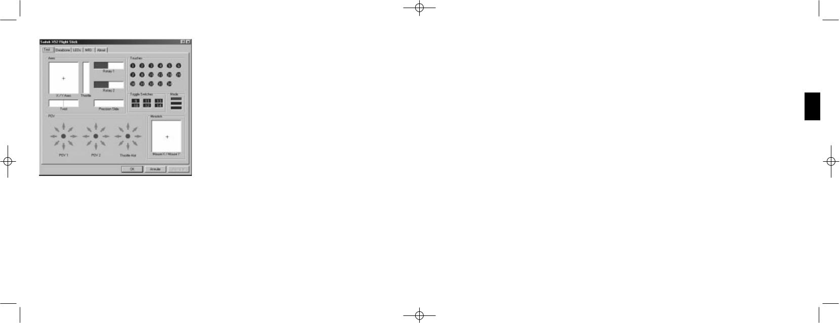
The Saitek X52 Flight Stick properties window consists of five separate tabs. You can view and change various controller settings in each tab. The settings you can change are described in the following sections.
Testing your controller
You can make sure that the various features of your controller are working correctly. You do this in the Test tab of the Saitek X52 Flight Stick properties window.
To test your controllers, follow the steps below:
ENGLISH
8 |
9 |

X52 manual(ok)(24/11/04) 2004.12.22 9:05 PM Page 10
1Click the Test tab.
The controller features that you can test are displayed below.
2Test each feature as required.
The way you do this varies, depending on what the feature does. It may, for example, involve pressing the corresponding button, or turning the corresponding rotary control.
The features you can test are explained in the following sections.
Testing axes
You can test the following axes and controls:
Feature |
Explanation |
X/Y Axes |
Move the flight stick backwards and forwards or from left to right. The + symbol |
|
moves in the X/Y Axes box, to show the drivers are picking up the stick |
|
movement correctly. |
Twist |
The vertical gray line represents the center point of the flight stick. Rotate the |
|
flight stick clockwise or anti-clockwise. This is the rudder that enables you to |
|
change direction outside the X and Y axes. If the drivers are detecting the |
|
movement correctly a red band is displayed on either side of the center point line. |
Throttle |
Move the throttle up or down to increase or decrease your acceleration. A red |
|
band shows the current rate of acceleration, ranging from 0% (no red) to the |
|
maximum acceleration at 100% (the box is filled with red). |
Rotary 1 and 2 |
Rotate the rotary controls on the throttle unit. These are user-defined via the SST |
|
programming software or within each game. They range from 0% (no red) to 100% |
|
(the box is filled with red). You may, for example, use them to control fuel mixture |
|
or radar gain. |
Precision Slide |
Move the slide control on the throttle unit. This is user-defined via the SST |
|
programming software or within each game, and ranges from 0% (no red) |
|
to 100% (the box is filled with red). You may, for example, use it to control |
|
pitch or fuel mixture. |
Testing buttons, toggle and mode switches
You can make sure button presses are being detected by the drivers. Press each button on your flight stick or throttle unit that you want to test, in turn. The corresponding numbered disc lights up in the Buttons panel of the Test tab.
Note: What each button does depends on the game in progress. You can, if you wish, assign functions to individual buttons using the SST programming software. See the SST programming software manual for details.
The numbered boxes in the Toggle Switches panel illuminate when you press the toggle switches on your flight stick unit.
The three red boxes in the Mode panel indicate which mode is currently selected. The top box represents mode 1, the middle box mode 2 and the lower box mode 3. Make sure your mode selector switch is working correctly by rotating the switch to change modes. The corresponding box in the Mode panel illuminates.
ENGLISH
10 |
11 |
X52 manual(ok)(24/11/04) 2004.12.22 9:05 PM Page 12
Testing POVs
Moving the POV controls on your flight stick in the various directions should illuminate the corresponding direction arrows in the POV panel. POV 1 is used to look around the cockpit. POV 2 can be configured to trigger four or eight different functions of your choice. See the SST programming software manual for details.
You can also make sure that movements of the Throttle Hat control cause the corresponding direction arrows in the POV panel to illuminate. As for POV 2, the throttle hat control can be configured to trigger four or eight different functions of your choice.
Testing the ministick
The ministick on the throttle unit is used to perform actions you would otherwise use your mouse for. Moving the ministick moves the + symbol in the Mouse X/Mouse Y box.
Maintaining deadzones
You can create deadzones for each range and axis your controller features move in. They reduce interference that may be caused by unintended movements of the flight stick and other controls. For example, you may want to move your stick in the X axis only, but find it difficult to avoid moving it in the Y axis as you do so. You can set up a deadzone in the Y axis so that these minor movements are not detected by the drivers.
What is a deadzone?
A deadzone is a part of the range in which an axis moves that is not detected by the drivers and so has no effect on the game in progress. It may be around the center point of the range, or at either end.
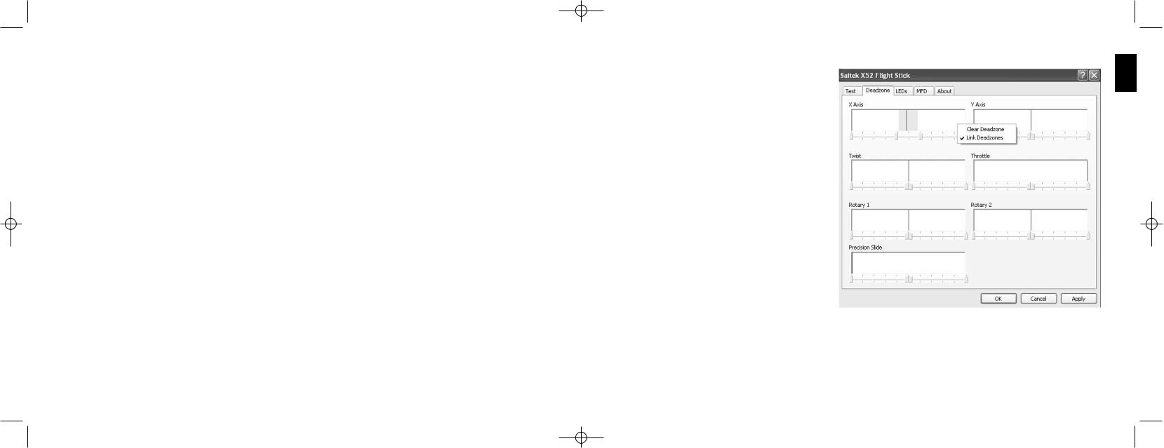
To maintain your deadzones
1Click the Deadzone tab.
The controls you can create deadzones for are shown, as follows:
Each axis is represented by a white box that contains a red line that represents where the control is currently sitting. Moving the corresponding control moves the red line. Use this line to determine exactly where your deadzone must begin and end. Beneath each box is a sliding scale. You use this to specify the size of each deadzone.
2Click on a slider on the sliding scale and drag it to where you want the deadzone to end. The area that represents the deadzone is shaded gray.
3Use the center sliders to maintain the deadzone around the center point of an axis. Use the sliders at either end to create deadzones at either end of the axis.
Tips: By default, clicking on either the right or the left slider in the pair moves both sliders. You can change
this if you just want to adjust one side of the deadzone. To do this, right-click anywhere in the white box and select Link Deadzones from the popup list of options displayed. Repeat this to link the pairs of sliders again.
You can clear existing deadzones for an axis by right-clicking anywhere in the white box and selecting Clear Deadzone. You can maintain deadzones for the following features of the Saitek X52 FCS:
ENGLISH
12 |
13 |

X52 manual(ok)(24/11/04) 2004.12.22 9:05 PM Page 14
Feature |
Explanation |
X Axis |
Movements of the stick from left to right or right to left. |
Y Axis |
Movements of the stick from back to front or front to back. |
Twist |
Rotations of the stick clockwise and anti-clockwise. |
Throttle |
Movements of the throttle to increase or decrease your speed. |
Rotary 1 |
Rotations of the small rotary control on the throttle. |
Rotary 2 |
Rotations of the large rotary control on the throttle. |
Precision Slide |
Movements of the slide |
control on the throttle. |
|
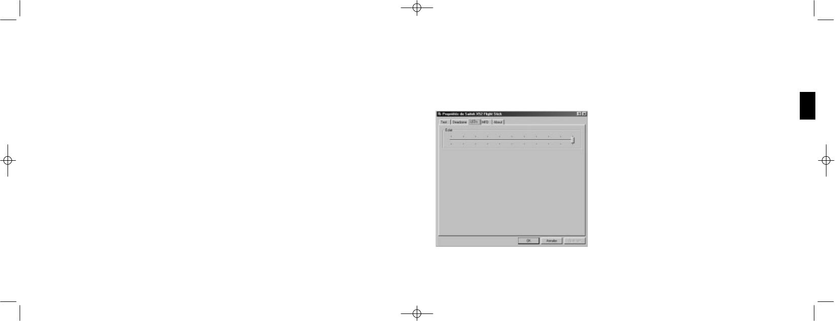
Maintaining your LED brightness
The authenticity of the flight control experience provided by your Saitek X52 FCS is enhanced by a number of LEDs on the throttle unit and flight stick. You can control the appearance of these LEDs, making them brighter or dimmer according to your preference.
ENGLISH
14 |
15 |
X52 manual(ok)(24/11/04) 2004.12.22 9:05 PM Page 16
To maintain LED brightness
1Click the LEDs tab.
A sliding scale is displayed, which you can use to choose how brightly the LEDs on your stick and throttle are displayed:
2Move the slider on the scale to adjust LED brightness. The LEDs change as you move the slider, so you can make sure they are as you want them to be. You can either:
¥Click and drag the slider along the scale. Or:
¥Click a point on the scale itself, to move the slider in graduated steps along the scale.
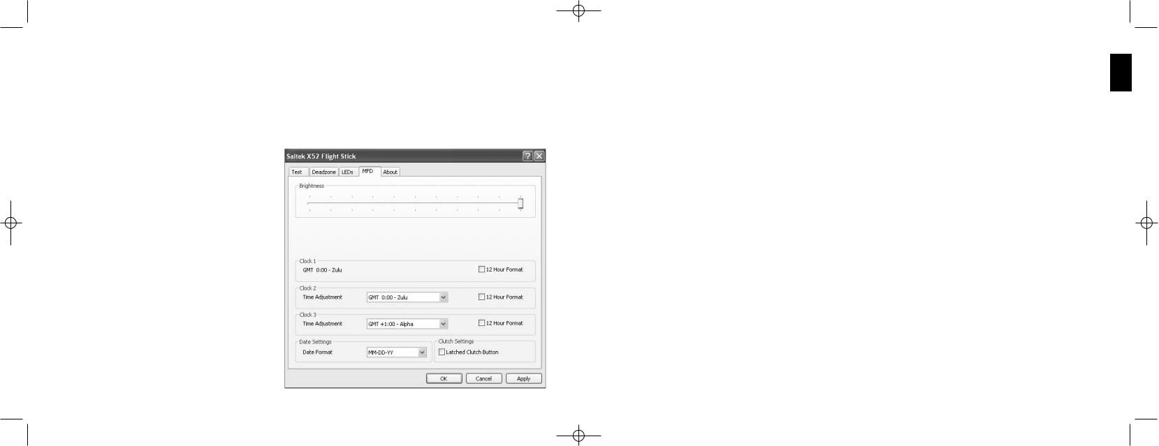
Maintaining MFD settings
Your Saitek X52 FCS flight stick unit includes an MFD, or Multi-Functional Display. You can control the way information is displayed in your MFD by changing various settings in the MFD tab:
What is the MFD?
The MFD is a screen that displays a variety of different information including, for example, the mode currently selected and today's date. It is part of the same unit as your throttle. The MFD itself and the way it works is explained in more detail in Using the MFD.
To change the brightness of your MFD
1Click the MFD tab.
A Brightness sliding scale is displayed at the top of the tab.
2 Change the brightness of your MFD by moving the slider along the scale. To move the slider, you can either:
¥Click and drag the slider along the scale. Or:
¥Click a point on the scale itself, to move the slider in graduated steps along the scale.
The brightness of your MFD changes as you move the slider. Use this to determine when the slider is in the right place.
Maintaining clock settings
Your MFD can display the current time in any time zone. You can choose the time zones displayed and the format in which the time for each zone is displayed.
You can have up to three different time zones available on your MFD. Greenwich Mean Time (GMT) is included by default. You can choose up to two additional time zones. When using your MFD, you switch between the three time zones, as required.
To change your clock settings
1Click the MFD tab.
This tab includes three panels in which you change the way time is displayed on your MFD. They are called Clock 1, Clock 2 and Clock 3.
Note: Clock 1 is set to GMT by default. You cannot change this.
2Choose additional time zones that you want to be able to view on your MFD in the Clock 2 and Clock 3 panels. You do this by selecting an option from the corresponding Time Adjustment drop-down list.
Each option is a time relative to GMT, for example GMT +1:00 is GMT plus one hour, and so on. Each time is also represented by an entry in the phonetic alphabet. For example, GMT is represented by 'Zulu' and GMT +12:00 by 'Mike'.
3Choose the format you want each time to be displayed in. To do this, either check or uncheck the corresponding 12 Hour Format checkbox.
When the box is unchecked, the time is displayed in 24 hour clock format, i.e. between 00:00 and 23:59. If it is checked, the time is shown in 12 hour clock format.
4Click Apply.
You can now view the current times in your chosen time zones on your MFD. See Using the MFD for details.
ENGLISH
16 |
17 |
|

X52 manual(ok)(24/11/04) 2004.12.22 9:05 PM Page 18
Maintaining date settings
The current date is displayed in the bottom right-hand corner of your MFD. You can choose how this date is displayed. You may, for example, prefer to see the month first, followed by day and year.
To change your date settings
1Click the MFD tab.
The format the date is currently displayed in on your MFD is shown in the Date Settings panel. 2 Select the format you want the date to be displayed in from the drop-down list.
3Click Apply.
Changing the way your clutch button works
The clutch button on your throttle is used to temporarily deactivate the buttons in the game in progress. This enables you to check what each button does without interrupting the game, and to select a different profile if required. See Viewing button names in Using the MFD for more information.
To change the way your clutch works, check or uncheck the Latched Clutch Button checkbox in the Clutch Settings panel and then click Apply.
When the box is checked, pressing and releasing the clutch deactivates the buttons in the game in progress. To reactivate the buttons, you must press and release the clutch again.
When the box is unchecked, the buttons are deactivated in the game only as long as the clutch is depressed. When you release the clutch, pressing buttons once again affects the game in progress.
Viewing notes and version information
Useful information about the SST programming software, along with a link by which you can download the latest version of the software, is provided. You can also view details
of the driver and software versions that you currently have installed. To view this information, click the About tab. This tab is shown above:
Using the MFD
The MFD, or Multi-Functional Display, is an integral part of your throttle unit. It displays a variety of information including button names, the current profile and today's date. It also provides a stopwatch feature.
You can change some of the settings that determine the way your MFD works. For example, you may want to increase the brightness of the display, or change the way the date is shown.
You do this in the MFD tab of the Saitek X52 Flight Stick Properties window. See Maintaining MFD settings in the section Maintaining your controller settings for more information.
Features of the MFD
The MFD is divided into three sections:
¥The mode section is at the top of the MFD and shows the currently selected mode. See Working with modes, below.
¥The center section of the MFD is used to view the names of buttons on your flight stick and throttle, and to view and change the current profile. See Working with profile information, below.
¥The time and date display is at the bottom of the MFD. It can show the current time in up to three time zones. It also includes the stopwatch. See Viewing the time and date and Using the stopwatch, below.
The layout of the MFD is shown right:
The three buttons beneath the MFD are used to change the time display and to operate the stopwatch.
Working with modes
The Saitek X52 FCS offers extensive opportunities for you to configure your controller to work the way you want it to. You do this by creating profiles, using the SST programming software. (See the SST programming software manual for details.) Within each profile,
ENGLISH
18 |
19 |

X52 manual(ok)(24/11/04) 2004.12.22 9:05 PM Page 20
you can create up to six different modes that determine the actions performed when you press buttons on the flight stick and throttle.
You can use your MFD to view the mode that is currently selected.
Changing the mode
You change the mode by rotating the mode selector switch on your flight stick. As you do this, the MODE number displayed on the MFD changes to reflect your selection.
Using additional modes
Three modes are available by default. You can increase this to six using the pinkie switch on your flight stick. To do this you must designate the pinkie switch to perform the same function as the Shift key, using the SST programming software. You can then select one of the additional modes by holding down the pinkie switch as you rotate the mode selector switch. When you do this, the word SHIFT is displayed in the mode section of your MFD.
Within each profile, you can use the following modes:
¥Mode 1
¥Mode 2
¥Mode 3
¥Mode 1 + Pinkie
¥Mode 2 + Pinkie
¥Mode 3 + Pinkie
Viewing the current modeThe mode that is currently selected is displayed in the top part of the MFD. This is shown in the following example:
If you have selected one of the three pinkie modes described above, the word SHIFT is displayed, because the pinkie switch is acting as a Shift key.
Working with profile information
You can use the center section of the MFD to view the names assigned to buttons on your flight stick and throttle. It also shows the names of the profile and mode currently selected.
Viewing button names
You can view the names assigned to buttons in the
current mode. You may use the SST programming software to create a number of profiles. Each profile may include up to six different modes, assigning different functions to individual buttons for use in different games.
If you've created profiles, you can view the names you've given to buttons in the selected mode in the current profile. If not, the standard name assigned to each button is displayed. The standard name reflects the function assigned to each
button when your Saitek X52 FCS is supplied.
ENGLISH
20 |
21 |
X52 manual(ok)(24/11/04) 2004.12.22 9:05 PM Page 22
To view the name of a button, press it as you normally would. Its name is displayed in the centreline of the MFD.
If a game is in progress, use the clutch to deactivate the buttons in the game. You can then press them and view their names without affecting the game. When supplied, the clutch is set up so that you must keep it depressed for as long as you want the buttons to remain inactive in the current game. You can change the way the clutch button works via the MFD tab of the Saitek X52 Flight Stick properties window. See Changing the way your clutch button works in Maintaining your controller settings for details.
Note: You cannot view button names if the Saitek X52 Flight Stick properties window is open.
Changing the current profile
You can use the MFD to change the current profile 'on the fly'. You may, for example, realise that you're not working in the correct profile for the game in progress.
To change the profile on the fly
1Press the clutch button. The LEDs on your clutch and on the main POV control on your flight stick begin to flash on and off. Pressing buttons does not affect the game in progress when the clutch is engaged.
Note: When supplied, the clutch is set up so that you must keep it depressed for as long as you want it to be engaged. You can change the way the clutch works via the MFD tab of the Saitek X52 Flight Stick properties window. See Changing the way your clutch button works in Maintaining your controller settings for details.
2Move the main POV control on your flight stick up (north) or down (south) to scroll through your profiles. As you do this, the profile names are displayed in the bottom row of the centre section of the MFD.
Note: You can use the MFD to access any folder on your computer. To open a folder, push the POV to the right (east). To move up a level, scroll through the files and folders in the current folder until [É] is displayed, and then push the POV to the right (east).
3Select the profile you want by moving the main
POV control right (east) when the profile's name is displayed on the MFD. It becomes the current profile and its settings are applied when you resume the game in progress.
Tip: You can clear the current profile by moving the POV left (west). The buttons on your stick and throttle return to their default settings.
4Release the clutch. The way you do this depends on your clutch settings. Either stop pressing the clutch button or press and release it.
Viewing the time and date
The lower part of the MFD displays the current time and date:
This part of the MFD can also be used as a stopwatch. You toggle between the two features by pressing the Function button. See Using the stopwatch, below, for more information about this feature.
Viewing the time
You can choose the time zone for which the current time is displayed from up to three available time zones. To move between the available time zones, press the up (Start/Stop) and down (Reset) buttons.
As you move between the three time zones, a number is displayed in the bottom right corner of the MFD (in place of the date). This number disappears after a few seconds.
Greenwich Mean Time (GMT) is available by default, and is represented by the number 1. You can choose which other time zones are available and the format in which each time is displayed. See Maintaining clock settings in the section Maintaining your controller settings for an explanation of this procedure.
Viewing the dateThe date is displayed in the bottom right-hand corner of the MFD. By default, it is shown in the format MMDDYY. You can change the date format, for example to DDMMYY. See Maintaining date settings in the section Maintaining your controller settings for an explanation of this procedure.
Using the stopwatch
The lower part of the MFD can also be used as a stopwatch. You toggle between the stopwatch and time displays by pressing the Function button. When the stopwatch is selected, the following is displayed:
To use the stopwatch
1 Press Start/Stop once. The number of seconds begins to increase.
2 Press Start/Stop again to stop the timer.
3 Press Reset to clear the time and return to 00:00.
ENGLISH
22 |
23 |
X52 manual(ok)(24/11/04) 2004.12.22 9:05 PM Page 24
Note: The timer initially shows minutes and seconds. If the time recorded reaches fifty-nine minutes and fifty-nine seconds, i.e. 59:59, it changes to show hours and minutes. This means the next reading after 59:59 is 01:00.
Using the rudder lock
You can deactivate the rudder feature on your flight stick by engaging the rudder lock. When you do this, the flight stick no longer rotates.
To use the rudder lock
1Position your flight stick unit with the three toggle switches (T1 to T6) facing you. The rudder lock can be seen at the base of the flight stick, on the left hand side. If you look closer, you will see that it is labelled RLOCK.
2Pull out the RLOCK switch. You may find the easiest way to do this is by using the thumb on your left hand. The twist action on the flight stick is now locked and you can no longer rotate it.
You can restore the rudder feature at any time by pushing the RLOCK switch back in.
Adjusting the handle
You can optimise your comfort when using the flight stick by adjusting the height of the hand rest and pinkie switch. If your hands are small, you can place the hand rest and pinkie switch in the highest position available. This reduces the distance between the trigger switch and pinkie switch, avoiding the need for you to stretch to reach both. If you have larger hands, you can maximise this distance and operate the flight stick in greater comfort.
To adjust the handle
1Position your flight stick unit with the three toggle switches (T1 to T6) facing away from you. A metal screw is clearly visible about one third of the way up the back of the handle.
2Loosen the screw by turning it anti-clockwise.
When the screw is loose enough, you can move it freely up and down within its slot on the back of the handle. Moving the screw also moves the hand rest and pinkie switch.
3Move the screw until the hand rest and pinkie switch are at the height you want.
4 Place the screw in the position that best suits your preferred height. There are five positions for you to choose from.
5Tighten the screw in position by turning it clockwise.
ROGER WILCO SOFTWARE
Roger Wilco is a "virtual walkie-talkie" that let's you talk to your friends as you play online games.
Highlights
¥Simple to use
¥Sound quality is equivalent or better than a CB radio.
¥Works with hundreds of Windows games.
¥Support for web integration and ICQ integration (Windows)
¥Windows Game Developer Tools.
¥Built-in channel browser to help you find other chatters
Disclaimer:
Roger Wilco is the property of GameSpy Industries and as such Saitek plc accepts no responsibility for this product. Any queries relating to this product should be directed to GameSpy Industries.
ENGLISH
24 |
25 |
X52 manual(ok)(24/11/04) 2004.12.22 9:05 PM Page 26
IMPORTANT INFORMATION
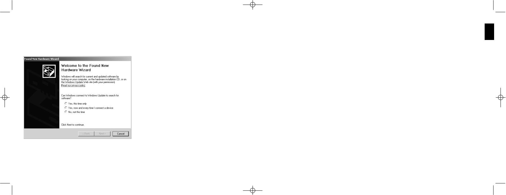
Important notice for Windows¨ XP users
If you have updated Windows XP to Service Pack 2 the following screen will appear when installing the Saitek Magic Mouse and Keyboard:
At this point we recommend that you select the No, not this time option and then click on Next to carry on with the installation.
A WORD ON DRIVER UPDATES
From time to time there may be updates to the driver and programming software for this product. You can check for the latest software updates by visiting the Saitek website and clicking on Downloads. A drop down menu will appear. Select
Drivers and Software.
FOR WINDOWS¨ XP USERS; DYNAMIC UPDATES:
You can check for Driver updates using Windows update. Click on Start on the bottom left hand corner of your monitor and then select Windows Update from the menu. Click on Driver Updates then select from any of the update options that appear in the centre of the window. When you have selected the relevant file to download go to the left hand side of the window and select Review and Install Updates. Finally click on Install Now from the centre section.
If you are using the SST Programming software then you will need to obtain an updated version to work with the new drivers that you have downloaded from Windows update. To obtain the new version of the software, open the Game Controllers icon in Control Panel, select the controller in the window and click Properties. At the top of the Properties window click the About tab and you will see a link that says ÒClick here to download the SST Programming SoftwareÓ. Click on the link and Windows will give a download prompt asking if you want to open the file or save it. Choose to save it to your preferred location on your computerÕs hard disk and the file will start downloading. Once the file has downloaded, find it on your hard disk and double click on it to install the programming software.
ENABLING YOUR CONTROLLER IN GAME
Most games support game controllers, which you can enable by using a [control] options menu within the Main Menu of the game itself.
If you are having trouble working out how to do this or if you're unsure whether the game being used supports game controllers, please refer to the user manual for that game for more help.
NOTE: Even if the game you are using does not support game controllers, it is possible to make the controller work in that game using the Saitek Smart Technology programming software (only installed if you chose to be an Advanced User when installing). Using the programming software allows you to program your controller with keyboard and mouse commands, enabling it to work in those games that only have support for keyboards and mice. For help using this powerful programming software, consult the Programming Your Saitek Controller with Saitek Smart Technology Programming Software section in this manual.
ENGLISH
26 |
27 |

X52 manual(ok)(24/11/04) 2004.12.22 9:05 PM Page 28
TROUBLESHOOTING
Q My computer is not recognizing the Saitek Controller Ð whatÕs wrong?
A1. Have you installed the drivers on the CD supplied with this product?
2.Check the cable connections. Unplug your controller and plug it back in, making certain that it is securely attached.
3.Have you tested your controller? Please refer to the "How to Test Your Controller" section in this manual for further information
Q2 The game I am playing does not recognize my controller - what's wrong?
A1. Ensure that you have conducted the checks in Q1 [above]
2. Does the game you are playing offer support for game controllers? Please refer to the "Enabling Your Controller in Game" section in this manual for further information.
HOW TO TEST YOUR CONTROLLER
¥You can do this at any time by Clicking on Start, then Settings and selecting Control Panel in Windows (XP users may only need to click on Start and then Control Panel)
¥Look for an icon called either Game Controllers or Gaming Options (XP users may have to click Printers and Other Hardware first).
¥Open the Game Controllers/Gaming Options window then the name your controller should show up.
¥Click on Properties and this will bring up the test screen.
¥Moving your controller and pressing the buttons should result in a response in this screen; if it's responding in there then you know that the controller is okay.
PROGRAMMING YOUR SAITEK CONTROLLER WITH SAITEK SMART TECHNOLOGY PROGRAMMING SOFTWARE
Introducing Saitek Smart Technology Programming Software
Saitek Smart Technology Programming Software (SST) is the software Saitek supplies to configure your Saitek controller for enhanced functionality. SST delivers a powerful set of features, allowing you to program your device with the ultimate configuration for total interaction. Despite a level of sophistication previously unseen in the market, and because of the Saitek Smart Technology inside, the software remains simple and intuitive to use.
Features of Smart Technology Programming Software:
¥Quick and easy setup in any game
¥Personalize the controller settings for your favorite games
¥Configure your controller with an on-screen 3D model and interface
¥Multiple setup option for each controller - ideal if a controller is used by several people
¥Program special moves with sophisticated timing features
¥Special game setups available as ÔProfilesÕ from the Saitek website and on the Smart Technology CD
¥Download the latest version of Saitek Smart Technology software from the Saitek website
What is a Profile?
A Profile is a custom setup for improved gameplay Ð consisting of a set of commands that are pre-assigned to the buttons or axes of your controller. We have provided some profiles for popular games on the Product Companion CD that accompanies your device.These profiles should be copied to the C:\Program Files\Saitek\Software directory on your PC before use.you can then open them from within the Profile Editor software by clicking File>Oper,at the top of the window;select the profile you wish to edit and then click Open.
How Do I Program My Controller?
After getting to know your controller, you can start creating your own personal Profiles with the Saitek Smart Technology programming software (SST). This software has virtually unlimited programming capabilities and allows you to customize the controller to your exact gaming needs.
The Profile Editor allows you to program the buttons on your controller to perform different actions within your games Ð this is especially useful if the game you are using does not have its own screen that allows reconfiguring of your buttons.
ENGLISH
28 |
29 |

X52 manual(ok)(24/11/04) 2004.12.22 9:05 PM Page 30
Getting Started
1Double-click on the Saitek Smart Technology icon the install left on your desktop.
2In the Profile Editor, choose the control to which you wish to assign a keyboard command. You do this by leftclicking on the controlÕs cell in the control list on the right of the screen.
3With the cursor flashing, type in the key commands and then click on the green tick mark when complete.
4Repeat this procedure for all the buttons you would like to program and then click File, Save at the top of the Profile Editor window.
5Give the profile a name (it is recommended you name it after the game for which the profile is intended) and then click Save.
6To enable the profile either click the Profile Now icon at the top of the Profile Editor (it looks like a black and yellow crosshair) or right-click on the controller icon in your taskbar and select the name of the profile from the pop-up list of options.
7You will notice that when a profile is loaded that the controller icon in your taskbar has a green square behind it, indicating that a profile is currently loaded. If you wish to unload a profile simply right-click on the controller icon and click Clear Profile from the pop-up list of options.
If you require more detailed assistance with using the SST Programming Software, click on Help at the top of the Profile Editor and then Manual.
TECHNICAL SUPPORT
CanÕt get your joystick to work Ð donÕt worry, weÕre here to help you!
Nearly all the products that are returned to us as faulty are not faulty at all - they have just not been installed properly.
If you experience any difficulty with this product, please first visit our website www.saitek.com. The technical support area will provide you with all the information you need to get the most out of your product and should solve any problems you might have.
If you do not have access to the internet, or if the website cannot answer your question, please contact your local Saitek Technical Support Team. We aim to offer quick, comprehensive and thorough technical support to all our users so, before you call, please make sure you have all the relevant information at hand.
To find your local Saitek Technical Support Center, please see the separate Technical Support Center sheet that came packaged with this product.
Conditions of Warranty
1 Warranty period is 2 years from date of purchase with proof of purchase submitted.
2Operating instructions must be followed.
3Product must not have been damaged as a result of defacement, misuse, abuse, neglect, accident, destruction or alteration of the serial number, improper electrical voltages or currents, repair, alteration or maintenance by any person or party other than our own service facility or an authorized service center, use or installation of non-Saitek replacement parts in the product or the modification of this product in any way, or the incorporation of this product into any other products, or damage to the product caused by accident, fire, floods, lightning, or acts of God, or any use violative of instructions furnished by Saitek plc.
4Obligations of Saitek shall be limited to repair or replacement with the same or similar unit, at our option. To obtain repairs under this warranty, present the product and proof of purchase (e.g. bill or invoice) to the authorized Saitek Technical Support Center (listed on the separate sheet packaged with this product) transportation charges prepaid.
Any requirements that conflict with any state or Federal laws, rules and/or obligations shall not be enforceable in that particular territory and Saitek will adhere to those laws, rules, and/or obligations.
5When returning the product for repair, please pack it very carefully, preferably using the original packaging materials. Please also include an explanatory note.
6IMPORTANT: To save yourself unnecessary cost and inconvenience, please check carefully that you have read and followed the instructions in this manual.
7This warranty is in Lieu of all other expressed warranties, obligations or liabilities. ANY IMPLIED WARRANTIES, OBLIGATIONS, OR LIABILITIES, INCLUDING BUT NOT LIMITED TO THE IMPLIED WARRANTIES OF MERCHANTABILITY AND FITNESS FOR A PARTICULAR PURPOSE, SHALL BE LIMITED IN DURATION TO THE DURATION OF THIS WRITTEN LIMITED WARRANTY. Some states do not allow limitations on how long an implied warranty lasts, so the above limitations may not apply to you. IN NO EVENT SHALL WE BE LIABLE FOR ANY SPECIAL OR CONSEQUENTIAL DAMAGES FOR BREACH OF THIS OR ANY OTHER WARRANTY, EXPRESS OR IMPLIED, WHATSOEVER Some states do not allow the exclusion or limitation of special, incidental or consequential damages, so the above limitation may not apply to you. This warranty gives you specific legal rights, and you may also have other rights which vary from state to state.
ENGLISH
30 |
31 |
X52 manual(ok)(24/11/04) 2004.12.22 9:05 PM Page 32
FCC Compliance and Advisory Statement
Warning: Changes or modifications to this unit not expressly approved by the party responsible for compliance could void the userÕs authority to operate the equipment.
This device complies with Part 15 of the FCC Rules. Operation is subject to the following two conditions:
1This device may not cause harmful interference, and
2This device must accept any interference received, including interference that may cause undesired operation
NOTE: This equipment has been tested and found to comply with the limits for a Class B digital device, pursuant to Part 15 of the FCC Rules. These limits are designed to provide reasonable protection against harmful interference in a residential installation. This equipment generates, uses and can radiate radio frequency energy and, if not installed and used in accordance with the instructions, may cause harmful interference to radio communications. However, there is no guarantee that interference will not occur in a particular installation. If this equipment does cause harmful interference to radio or television reception, which can be determined by turning the equipment off and on, the user is encouraged to try to correct the interference by one or more of the following measures:
¥Reorient or relocate the receiving antenna
¥Increase the separation between the equipment and receiver
¥Connect the equipment into an outlet on a circuit different from that to which the receiver is connected
¥Consult the dealer or an experienced radio/TV technician for help
Saitek Industries, 2295 Jefferson Street, Torrance, CA 90501, USA
Canadian EMC statement
This Class B digital apparatus complies with Canadian ICES-003.
Cet appareil numŽrique de la classe B est conforme ˆ la norme NMB-003 du Canada.
32
CONTROLEUR DE VOL SAITEK X52 - VUE GENERALE DU PRODUIT JOYSTICK
Ajustement de la prise ˆ 5 positions pour tous les types de mains.
DŽtente ˆ 2 Žtapes en mŽtal |
3 commutateurs |
DŽtruisez vos ennemis ˆ l'aide d'une |
MontŽs sur ressort et positionnŽs |
dŽtente facile, prŽcise et durable. Les |
sur la base pour 6 commandes |
deux Žtapes peuvent •tre programmŽes ˆ |
programmables supplŽmentaires |
l'aide de fonctions de tirs distinctes. |
en vol. |
Touche Pinkie (petit doigt) en mŽtal, avec dŽtente rapide capable de remplir la fonction Shift (Majuscule) et ainsi permettre de doubler le nombre de vos commandes programmables.
Lance-missiles Soulevez le clapet de protection ˆ ressort pour activer les tirs de missiles.
2 chapeaux multidirectionnels ˆ 8 positions - 1 prŽdŽfini comme point de vue, sŽlectionnez ˆ partir de plusieurs angles de vue et assignez des commandes frŽquemment utilisŽes.
Palonnier avec fonction 3D Twist sur le joystick pour un contr™le prŽcis du palonnier : avec mŽcanisme intŽgrŽ de verrouillage du palonnier.
MŽcanisme de centrage de prŽcision Technologie de non-contact des axes X et Y et force constante du ressort pour un meilleur contr™le et une meilleure durabilitŽ.
33
SŽlecteur de mode Commutateur rotatif ˆ 3 positions avec voyant LED tricolore  indiquant le mode sŽlectionnŽ.
Touches 3 tirs Touches rŽtroŽclairŽes, positionnŽes de fa•on judicieuse sur le haut du joystick, pour un acc•s rapide dans le feu de l'action.
CaractŽristiques gŽnŽrales RŽtro-Žclairage
Touches illuminŽes et affichage multi-fonctions (MFD) : idŽal pour jouer dans des environnements ˆ la luminositŽ restreinte et se faire repŽrer au milieu de la foule ! Ajustement de la luminositŽ via un panneau de configuration Windows.
Parties mŽtalliques
Certaines pi•ces sont en mŽtal pour une meilleure durabilitŽ et un plus grand confort lors des parties les plus longues.
FRAN‚AIS

X52 manual(ok)(24/11/04) 2004.12.22 9:05 PM Page 34
MANETTE DES GAZ
2 touches de tirs PositionnŽes de fa•on judicieuse sur le haut du joystick pour un acc•s rapide dans le feu de l'action.
Bouton de souris |
Simulateur de souris, |
gauche. |
pouvant Žgalement |
|
fonctionner comme |
|
chapeau |
|
multidirectionnel. |
Glissi•re facile ˆ |
|
actionner du pouce |
|
pour contr™ler les |
|
axes de tangage, de |
|
roulis et de lacet ou |
|
pour effectuer un |
|
zoom avant/arri•re. |
|
Le syst•me d'affichage multi-fonctions (MFD) indique :
Le mode de jeu et la fonction Shift (Majuscule)
Le sŽlectionneur de mode sur le dessus du joystick permet de choisir le mode de jeu.
Zone de texte dŽfinie par l'utilisateur
-indique le nom de la commande assignŽe au bouton lorsqu'elle est activŽe.
-donne le nom du profil utilisŽ et permet de sŽlectionner rapidement un profil. Les profils peuvent Žgalement •tre modifiŽs pendant la partie en appuyant sur le bouton d'embrayage et en faisant dŽfiler tous les profils disponibles en dŽpla•ant le chapeau multidirectionnel vers le haut et vers le bas. DŽplacez le chapeau vers la gauche pour dŽsŽlectionner ce profil ou vers la droite pour l'activer.
Affichage multi-horaires
Fuseau horaire (rŽgler l'heure locale ˆ l'origine et ˆ la destination dans le panneau de configuration)
Le jour, le mois et l'heure peuvent •tre formatŽs
 Chronom•tre pour la durŽe de vol
Deux molettes pour un contr™le des axes de tangage, de roulis et de lacet
 Bouton d'embrayage (I) DŽclenchant le mode sŽcuritŽ pour sŽlectionner rapidement un profil ou pour afficher la fonctionnalitŽ des touches en affichage multi-fonctions sans craindre d'activer les commandes.
Chapeau multidirectionnel ˆ 8 positions
Pour sŽlectionner diffŽrents angles de vue et assigner des commandes frŽquemment utilisŽes.
Molette de dŽfilement situŽe ˆ l'arri•re de la manette des gaz avec activation par l'index et bouton intŽgrŽ.
34
Contr™le progressif de la manette des gaz
Action progressive avec ajustement de la tension et de la dŽtente pour programmer les phases de ralenti (0- 20%) et de post-combustion (80-100%).
DƒMARRER
INSTALLATION POUR LES UTILISATEURS DE WINDOWS¨ XP
A) Pilotes pour des utilisateurs type uniquement
1L'ordinateur allumŽ, fermez tous les programmes en cours d'exŽcution et insŽrez le CD Saitek Smart Technology dans votre lecteur de CD-ROM.
2Lorsque l'Žcran d'introduction appara”t, cliquez sur Installer le logiciel pour continuer. Si le CD ne se met pas en route automatiquement, sŽlectionner DŽmarrer dans la barre de t‰ches Windows, puis ExŽcuter, puis tapez D:\Setup.exe (D : Žtant votre lecteur de CD) et cliquez sur OK.
3Lorsque l'Žcran de bienvenue appara”t, cliquez sur Suivant pour continuer.
4Apr•s avoir lu l'avertissement, sŽlectionnez I accept the terms of the Disclaimer (J'accepte les termes de cet avertissement) et cliquez sur Suivant pour continuer.
5A l'Žcran d'installation du pilote, si vous ne l'avez pas encore fait, veuillez brancher votre contr™leur et cliquer sur
Suivant.
6Cliquez sur Suivant dans les deux fen•tres suivantes et ˆ l'Žcran de mise ˆ jour des drivers, cliquez sur Suivant pour tester votre contr™leur
7Lorsque l'Žcran de contr™le Saitek appara”t, essayez tous les boutons de votre contr™leur, ainsi que les contr™les, afin de vous assurer qu'ils fonctionnent correctement. Lorsque vous avez terminŽ, veuillez cliquer sur OK.
8A l'Žcran de configuration du logiciel, sŽlectionnez Ne pas installer le logiciel de programmation SST et cliquez sur Suivant. Le logiciel de programmation peut •tre installŽ ˆ une date ultŽrieure en suivant l'instruction (B) figurant ci-dessous.
9Sur l'Žcran d'enregistrement, sŽlectionner Cocher cette case pour enregistrer maintenant, et suivez les instructions donnŽes ˆ l'Žcran. Vous pouvez Žgalement choisir de sŽlectionner cette option plus tard.
10 Cliquez sur Terminer pour terminer l'installation.
B) Pilotes et Logiciel de Programmation pour les Utilisateurs AvancŽs
1Suivez les points 1 ˆ 7 de A). A l'Žcran Configuration du logiciel, sŽlectionnez Installez le logiciel de programmation SST et cliquez sur Suivant.
2A l'Žcran Configuration du logiciel, cliquez sur Suivant et suivez les instructions donnŽes ˆ l'Žcran. Vous •tes alors
35
FRAN‚AIS
X52 manual(ok)(24/11/04) 2004.12.22 9:05 PM Page 36
invitŽ(e) ˆ installer des fonctions telles que la souris Saitek Magic Mouse ou le clavier Saitek Magic Keyboard (c'est le nom que XP donne aux diffŽrents ŽlŽments de votre contr™leur Saitek). Cliquez toujours sur Suivant, Continuer de toute fa•on et Terminer pour accepter l'installation jusqu'ˆ ce que vous obteniez le message Installation of programming software successful (Installation rŽussie du logiciel de programmation).
3A l'Žcran d'enregistrement, sŽlectionnez Cliquez pour vous enregistrer maintenant et suivez les instructions ˆ l'Žcran, ou ne sŽlectionnez pas cette option pour vous enregistrer plus tard.
4A la fin du processus d'installation, vous aurez la possibilitŽ d'exŽcuter l'Žditeur de profil (Run Profile Editor), ce qui vous permettra de visualiser en 3D votre environnement de programmation. Si vous ne voulez pas exŽcuter l'Žditeur de profil, cliquez simplement sur Terminer pour complŽter le processus d'installation.
INSTALLATION POUR LES UTILISATEURS DE WINDOWS¨ 2000
A) Pilotes pour des utilisateurs type uniquement
1L'ordinateur allumŽ, fermez tous les programmes en cours d'exŽcution et insŽrez le CD Saitek Smart Technology dans votre lecteur de CD-ROM.
2Quand l'Žcran d'introduction appara”t, cliquez sur Installer le logiciel pour continuer. Si le CD ne dŽmarre pas automatiquement, sŽlectionnez DŽmarrer dans la barre des t‰ches Windows¨ puis ExŽcuter. Tapez alors D:\Setup.exe et cliquez sur OK (D:\ correspond ˆ votre lecteur de CD-ROM).
3Lorsque l'Žcran de bienvenue appara”t, cliquez sur Suivant pour continuer.
4Apr•s avoir lu l'avertissement, sŽlectionnez I accept the terms of the Disclaimer (J'accepte les termes de cet avertissement) et cliquez sur Suivant pour continuer.
5L'Žcran Device Driver Installation (Installation du pilote) s'affiche. Cliquez sur Suivant et suivez les instructions donnŽes ˆ l'Žcran.
6Lorsqu'on vous y invite, branchez le connecteur USB de votre contr™leur ˆ votre ordinateur puis cliquez sur Configure (Configurer).
7Une fois l'Žcran Controller Properties affichŽ, cliquez sur Suivant pour afficher l'Žcran Test.
8Essayez maintenant tous les boutons et contr™les de votre contr™leur afin de vŽrifier qu'il fonctionne correctement. Lorsque vous avez terminŽ, veuillez cliquer sur OK.
9A l'Žcran Programming Software (Logiciel de programmation), cliquez sur Typical User (Usager typique) puis sur
Suivant.
10 A l'Žcran Registration (Enregistrement), sŽlectionnez Register my Saitek controller online (Enregistrer en ligne
mon contr™leur Saitek) et suivez les instructions donnŽes ˆ l'Žcran ou sŽlectionnez Register Later (Enregistrer plus tard) et cliquez sur Suivant.
11 Cliquez sur Terminer pour terminer l'installation.
B) Pilotes et Logiciel de Programmation pour les Utilisateurs AvancŽs
1Suivez les points 1 ˆ 8 de A). A l'Žcran Programming Software (Logiciel de programmation), sŽlectionnez Advanced User (Utilisateur avancŽ) et cliquez sur Suivant.
2A l'Žcran Programmable Controller Drivers (Pilotes du contr™leur programmable), cliquez sur Update (Mise ˆ jour) et suivez les instructions donnŽes ˆ l'Žcran.
3A l'Žcran Installation of programming software successful (Installation rŽussie du logiciel de programmation), cliquez sur Suivant.
4A l'Žcran Registration (Enregistrement), sŽlectionnez Register (Enregistrer) et suivez les instructions donnŽes ˆ l'Žcran ou sŽlectionnez Register Later (Enregistrer plus tard) et cliquez sur Suivant.
5A la fin du processus d'installation, vous aurez la possibilitŽ d'exŽcuter l'Žditeur de profil (Run Profile Editor), ce qui vous permettra de visualiser en 3D votre environnement de programmation. Si vous ne voulez pas exŽcuter l'Žditeur de profil, cliquez simplement sur Terminer pour complŽter le processus d'installation.
INSTALLATION POUR LES UTILISATEURS DE WINDOWS¨ 98 ET ME
A) Pilotes pour des utilisateurs type uniquement
1L'ordinateur allumŽ, fermez tous les programmes actifs et insŽrez le CD Saitek Smart Technology dans votre lecteur de CD-Rom.
2Lorsque l'Žcran d'introduction appara”t, cliquez sur Installer le logiciel pour continuer. Si le CD ne se met pas en route automatiquement, sŽlectionner DŽmarrer dans la barre de t‰ches Windows, puis ExŽcuter, puis tapez D:\Setup.exe (D : Žtant votre lecteur de CD) et cliquez sur OK.
3Dans le premier Žcran qui s'affiche, cliquez sur Suivant pour continuer.
4Apr•s avoir lu et acceptŽ l'avertissement, cliquez sur Suivant pour continuer.
NB : Votre contr™leur ne fonctionnera que si la version 8.1 (ou une version plus rŽcente) de Microsoft¨ DirectX¨ a ŽtŽ installŽe sur votre ordinateur. Cet assistant d'installation dŽtectera automatiquement si une version de ce logiciel a dŽjˆ ŽtŽ installŽe. Vous aurez Žgalement la possibilitŽ, si nŽcessaire, d'installer ce logiciel directement ˆ partir du
FRAN‚AIS
36 |
37 |

X52 manual(ok)(24/11/04) 2004.12.22 9:05 PM Page 38
CD Saitek Product Companion.
Si l'assistant vous invite ˆ installer Microsoft¨ DirectX¨ 8.1, cliquez sur Installer et suivez les instructions donnŽes ˆ l'Žcran. RedŽmarrez votre ordinateur lorsqu'on vous y invite. VŽrifiez que votre CD Saitek est dans votre lecteur de CD-Rom avant de redŽmarrer votre ordinateur. Une fois ce logiciel installŽ, l'installation de votre pilote reprend automatiquement ˆ l'Žtape suivante.
5Suivez les instructions ˆ l'Žcran et, lorsqu'on vous y invite, sŽlectionnez Oui, je veux redŽmarrer mon ordinateur maintenant.
6Apr•s avoir redŽmarrŽ l'ordinateur, l'Žcran d'Installation du pilote du pŽriphŽrique s'affiche. Cliquez sur Suivant et suivez les instructions donnŽes ˆ l'Žcran.
7Lorsqu'on vous y invite, connectez votre contr™leur au port USB de votre ordinateur.
8L'Žcran PropriŽtŽs du contr™leur s'affiche. Cliquez sur Suivant pour afficher l'Žcran Test.
9 Essayez maintenant tous les boutons et contr™les de votre contr™leur afin de vŽrifier qu'il fonctionne correctement.
10A l'Žcran Logiciel de programmation, sŽlectionnez Utilisateur type puis cliquez sur Suivant.
11A l'Žcran d'Enregistrement, sŽlectionner Enregistrer en ligne mon contr™leur Saitek, cliquez sur Suivant et suivez les instructions donnŽes ˆ l'Žcran ou sŽlectionnez Enregistrer plus tard et cliquez sur Suivant.
12Cliquez sur Terminer pour terminer l'installation.
B) Pilotes et Logiciel de Programmation pour les Utilisateurs AvancŽs
1Suivez les Žtapes d'installation 1 ˆ 9 de A) puis, ˆ l'Žcran du logiciel de programmation, sŽlectionnez Utilisateur avancŽ et cliquez sur Suivant.
2A l'Žcran Pilotes du contr™leur programmable, cliquez sur Mise ˆ jour et suivez les instructions donnŽes ˆ l'Žcran. Vous •tes alors invitŽ ˆ insŽrer le CD Windows¨. NE PAS insŽrer le CD : cliquez simplement sur OK. A l'Žcran suivant, tapez C:\windows\system dans l'invitation, cliquez sur OK et suivez les instructions donnŽes ˆ l'Žcran.
3A l'Žcran Installation rŽussie du logiciel de programmation, cliquez sur Suivant.
4A l'Žcran d'Enregistrement, sŽlectionnez Enregistrer en ligne mon contr™leur Saitek, cliquez sur Suivant et suivez les instructions donnŽes ˆ l'Žcran ou sŽlectionnez Enregistrer plus tard et cliquez sur Suivant.
5Une fois l'installation terminŽe, vous pourrez alors, si vous le dŽsirez, ExŽcuter l'Editeur de profil, ce qui vous permettra de visualiser en 3 dimensions votre environnement de programmation. Si vous ne dŽsirez pas exŽcuter l'Žditeur de profil, il vous suffit de dŽsactiver la case ˆ cocher et de cliquer sur Terminer pour achever l'installation.
GESTION DES RƒGLAGES DE VOTRE CONTRïLEUR
Votre simulateur de vol Saitek X52 est fourni pr•t ˆ l'emploi. Cependant, nous voulons que vous l'utilisiez au maximum de ses potentialitŽs. Pour cette raison, nous avons intŽgrŽ un syst•me vous permettant de modifier les diffŽrents rŽglages de votre joystick et de votre manette des gaz. Vous pourrez, par exemple, faire varier l'intensitŽ lumineuse des diodes LED, vŽrifier si votre joystick fonctionne correctement ou modifier la fa•on dont la date est affichŽe sur votre affichage multi-fonctions (MFD).
Pour cela, il vous suffit de changer les rŽglages de votre contr™leur dans la fen•tre de propriŽtŽs Saitek X52 Flight Stick. Vous pouvez ouvrir cette fen•tre de deux fa•ons diffŽrentes :
¥En double-cliquant sur l'ic™ne Contr™leurs de jeu dans le Panneau de configuration puis en cliquant sur PropriŽtŽs dans la fen•tre Contr™leurs de jeu ainsi affichŽe.
- ou -
¥Si le logiciel de programmation SST a ŽtŽ installŽ, cliquez ˆ droite sur l'ic™ne de crŽation de profil Saitek X52 Flight Stick dans votre barre des t‰ches et sŽlectionnez Panneau de configuration dans la liste des options qui s'affiche ˆ l'Žcran.
La fen•tre de propriŽtŽs Saitek X52 Flight Stick est composŽe de cinq onglets diffŽrents. Vous pouvez visualiser et changer les diffŽrents rŽglages du contr™leur dans chaque onglet. Les rŽglages que vous pouvez changer sont dŽcrits dans les sections suivantes.
Tester votre contr™leur
Vous pouvez vous assurer que les diffŽrentes caractŽristiques de votre contr™leur fonctionnent correctement. Pour cela, cliquez sur l'onglet Test dans la fen•tre de propriŽtŽs Saitek X52 Flight Stick.
Pour tester vos contr™leurs, suivez les Žtapes suivantes :
1Cliquez sur l'onglet Test.
Les caractŽristiques du contr™leur que vous pourrez tester sont affichŽes, comme indiquŽ ci-dessous :
FRAN‚AIS
38 |
39 |
X52 manual(ok)(24/11/04) 2004.12.22 9:05 PM Page 40
2Testez les caractŽristiques ˆ Žvaluer. Pour cela, tout dŽpend de la caractŽristique en question et de ses fonctions. Vous devrez, par exemple, parfois appuyer sur la touche correspondante ou tourner la commande rotative correspondante.
Les caractŽristiques que vous pouvez tester sont dŽcrites dans les sections suivantes.
Tester les axes
Vous pouvez les axes et les contr™les suivants :
CaractŽristique |
Explication |
X/Y Axes (Axes X/Y) |
DŽplacez le joystick vers l'avant et vers l'arri•re ou de gauche ˆ droite. |
|
Le symbole + se dŽplace dans la fen•tre X/Y Axes pour indiquer que |
|
les pilotes dŽtectent correctement les mouvements du joystick. |
Twist |
La ligne grise verticale reprŽsente le point central du manche ˆ balai. |
|
Faites tourner le manche ˆ balai dans le sens des aiguilles d'une |
|
montre et dans le sens inverse. Le palonnier vous permet de changer |
|
de direction en dehors des axes X et Y. Si les pilotes dŽtectent |
|
correctement le mouvement, une bande rouge est affichŽe de |
|
chaque c™tŽ de la ligne de point centrale. |
Throttle (Manette des gaz) |
DŽplacez la manette des gaz vers le haut ou vers le bas pour augmenter |
|
ou diminuer l'accŽlŽration. Une bande rouge indique le pourcentage |
|
actuel d'accŽlŽration, allant de 0% (pas de rouge) ˆ une accŽlŽration |
|
maximale de 100% (le cadre est enti•rement rouge). |
Rotary 1 et 2 |
Faites tourner les commandes rotatives situŽes sur l'unitŽ de la manette |
|
des gaz. Celles-ci sont dŽfinies gr‰ce au logiciel de programmation SST |
|
ou au sein de chaque jeu. Ils vont de 0% (pas de rouge) ˆ 100% (le |
|
cadre est enti•rement rouge). Vous pouvez, par exemple, les utiliser |
|
pour contr™ler le mŽlange de carburant ou l'intensitŽ du radar. |
Precision Slide (glissi•re de prŽcision) |
Faites tourner la commande ˆ glissi•re sur l'unitŽ de la manette des gaz. |
|
Celle-ci est dŽfinie via le logiciel de programmation SST ou au sein de |
|
chaque jeu, et va de 0% (pas de rouge) ˆ 100% (le cadre est |
|
enti•rement rouge). Vous pourrez, par exemple, l'utiliser pour |
|
contr™ler le tangage ou le mŽlange de carburant. |
FRAN‚AIS
40 |
41 |
X52 manual(ok)(24/11/04) 2004.12.22 9:05 PM Page 42
Tester les touches, les commutateurs et les commutateurs de mode
Vous pourrez vous assurer que lorsque vous appuyez sur une touche ou un bouton, cette action est bien dŽtectŽe par les pilotes. Appuyez, l'un apr•s l'autre, sur chaque touche de votre joystick ou de votre manette des gaz que vous dŽsirez tester. Le cercle numŽrotŽ correspondant s'allume dans le panneau Touches de l'onglet Test.
NB : La fonction de chacune des touches dŽpend du jeu utilisŽ. Vous pouvez, si vous le dŽsirez, assigner des fonctions diffŽrentes pour chaque touche en utilisant le logiciel de programmation SST. Se rŽfŽrer au Manuel de programmation SST pour de plus amples dŽtails.
Les touches numŽrotŽes dans le panneau Toggle Switches s'allument lorsque vous appuyez sur les commutateurs de votre joystick.
Les trois encadrŽs rouges dans le panneau Mode indiquent le mode actuellement sŽlectionnŽ. L'encadrŽ supŽrieur reprŽsente le mode 1, celui du milieu le mode 2 et l'encadrŽ infŽrieur le mode 3. Assurez-vous que le commutateur de sŽlection de mode fonctionne correctement en faisant tourner le commutateur pour changer de mode. L'encadrŽ correspondant dans le panneau Mode s'allume alors.
Tester le commutateur Point de vue (POV)
DŽplacez les commandes POV de votre joystick dans diffŽrentes directions et vous verrez (normalement) les fl•ches correspondantes s'allumer dans le panneau POV. POV 1 sert ˆ regarder autour de vous dans le cockpit. POV 2 peut •tre configurŽ pour dŽclencher quatre ou huit fonctions diffŽrentes de votre choix. Se rŽfŽrer au Manuel de programmation SST pour de plus amples dŽtails.
Vous pouvez Žgalement vŽrifier que les mouvements de la commande Throttle Hat (chapeau multi-directionnel) allument bien toutes les fl•ches dans le panneau POV. Pour POV 2, la commande du chapeau multi-directionnel peut •tre configurŽe pour dŽclencher quatre ou huit fonctions diffŽrentes de votre choix.
Tester le mini-stick
Le mini-stick sur la manette des gaz sert ˆ effectuer des actions pour lesquelles vous utiliseriez gŽnŽralement la souris. En dŽpla•ant le mini-stick, le symbole + se dŽplace dans l'encadrŽ Mouse X/Mouse Y.
Gestion des zones mortes
Vous pouvez dŽfinir des zones mortes pour chaque gamme/axe dans lequel/dans laquelle les caractŽristiques de votre contr™leur se dŽplacent. Ces zones mortes permettront de rŽduire les interfŽrences causŽes par des mouvements non voulus du manche ˆ balai et des autres commandes. Par exemple, vous prŽfŽrerez peut-•tre dŽplacer votre stick uniquement sur l'axe X, mais avoir du mal ˆ Žviter, ce faisant, de le dŽplacer sur l'axe Y. Vous pouvez ainsi dŽfinir une zone morte dans l'axe Y de fa•on ˆ ce que ces petits mouvements ne soient pas dŽtectŽs par les pilotes de jeu.
Qu'est-ce qu'une zone morte ?
Une zone morte est une partie de la plage de mouvements dans laquelle un dŽplacement de l'axe n'est pas dŽtectŽ par les pilotes, et donc n'a aucun effet sur la partie en cours. Cette zone peut •tre dŽfinie comme Žtant au centre de la plage, ou ˆ chaque extrŽmitŽ de celle-ci.
FRAN‚AIS
Pour gŽrer vos zones mortes
1Cliquez sur l'onglet Deadzone (Zone morte).
Les commandes pour lesquelles vous pouvez dŽfinir des zones mortes s'affichent, comme indiquŽ ci-dessous :
Chaque axe est reprŽsentŽ par un encadrŽ blanc contenant une ligne rouge qui reprŽsente l'endroit o• la commande est actuellement rŽglŽe. En dŽpla•ant la commande correspondante, vous dŽplacerez la ligne rouge. Utilisez cette ligne pour dŽterminer exactement l'emplacement o• votre zone morte doit commencer et se terminer. En dessous de chaque encadrŽ, vous trouverez une Žchelle ˆ glissi•re. Vous pourrez l'utiliser pour spŽcifier la taille de chaque zone morte.
2Cliquez sur une glissi•re et faites-la glisser ˆ l'endroit o• vous dŽsirez que la zone morte se termine. La zone reprŽsentant la zone morte est surlignŽe en gris.
3Utilisez les glissi•res centrales pour maintenir la zone morte autour du point central d'un axe. Utilisez les glissi•res
42 |
43 |
X52 manual(ok)(24/11/04) 2004.12.22 9:05 PM Page 44
situŽes de chaque c™tŽ pour crŽer des zones mortes ˆ chaque extrŽmitŽ de l'axe.
Conseils : Par dŽfaut, vous pourrez dŽplacer les deux glissi•res par paire en cliquant soit sur celle de droite, soit sur celle de gauche. Vous pouvez changer ce rŽglage si vous voulez uniquement ajuster un c™tŽ de la zone morte. Pour cela, cliquez ˆ droite n'importe o• dans l'encadrŽ blanc et sŽlectionnez Link Deadzones dans la liste d'options qui appara”t ˆ l'Žcran. RŽitŽrez cette action pour que les paires de glissi•res soient ˆ nouveau liŽes dans leurs dŽplacements.
Vous pouvez remettre ˆ blanc la zone morte d'un axe en cliquant ˆ droite n'importe o• dans l'encadrŽ blanc et en sŽlectionnant Clear Deadzone.
Vous pouvez dŽfinir les caractŽristiques suivantes des zones mortes de votre contr™leur de simulation de vol Saitek X52 :
CaractŽristique |
Explication |
X Axis |
Mouvements du joystick de gauche ˆ droite ou de droite ˆ gauche. |
Y Axis |
Mouvements du joystick de l'arri•re ˆ l'avant ou de l'avant ˆ l'arri•re. |
Twist |
Rotation du joystick dans le sens des aiguilles d'une montre et dans le sens inverse. |
Throttle |
Mouvements de la manette des gaz pour augmenter ou diminuer l'accŽlŽration. |
Rotary 1 |
Rotations de la petite commande rotative sur la manette des gaz. |
Rotary 2 |
Rotations de la grande commande rotative sur la manette des gaz. |
Precision Slide |
Mouvement de la commande ˆ glissi•re sur la manette des gaz. |
Gestion de la luminositŽ des diodes LED
La simulation de vol est rendue d'autant plus crŽdible gr‰ce aux diffŽrentes diodes LED situŽes sur la manette des gaz et sur le joystick de votre contr™leur de jeu Saitek X52. Vous pouvez modifier l'apparence de ces diodes LED, en rendant l'intensitŽ lumineuse plus ou moins forte, selon vos prŽfŽrences.
Pour gŽrer la luminositŽ des diodes LED
1Cliquez sur l'onglet LEDs.
Une commande ˆ glissi•re s'affiche. Utilisez-la pour sŽlectionner l'intensitŽ lumineuse des LED sur votre joystick et votre manette des gaz :
2DŽplacez la glissi•re sur l'Žchelle pour ajuster la luminositŽ des diodes. Les diodes LED changent d'aspect lorsque vous dŽplacez la glissi•re : choisissez donc l'apparence qui vous convient le mieux. Vous pouvez :
FRAN‚AIS
44 |
45 |

X52 manual(ok)(24/11/04) 2004.12.22 9:05 PM Page 46
¥Cliquer et faire glisser la glissi•re le long de l'Žchelle. - ou -
¥Cliquer sur un point de l'Žchelle pour dŽplacer la glissi•re par Žtapes graduŽes le long de cette Žchelle.
Gestion des rŽglages de l'affichage multi-fonctions (MFD)
Votre contr™leur de simulation de vol Saitek X52 comprend un MFD, ou Affichage multi-fonctions. Vous pouvez contr™ler la fa•on dont les informations sont affichŽes dans votre MFD en modifiant les diffŽrents rŽglages dans l'onglet MFD :
Qu'est-ce que le MFD ?
Le MFD est un Žcran qui affiche diffŽrentes informations, notamment le mode actuellement sŽlectionnŽ ou la date actuelle. Cela fait partie de la m•me unitŽ que votre manette des gaz. Le MFD et son fonctionnement sont dŽcrits plus en dŽtail dans la partie intitulŽe Utilisation du MFD.
Pour changer la luminositŽ de votre MFD
1Cliquez sur l'onglet MFD.
Une Žchelle ˆ glissi•re intitulŽe Eclat est affichŽe en haut de l'onglet.
2Modifiez la luminositŽ de votre MFD en dŽpla•ant la glissi•re le long de l'Žchelle. Pour dŽplacer la glissi•re, vous pouvez :
¥Cliquer et faire glisser la glissi•re le long de l'Žchelle. - ou -
¥Cliquer sur un point de l'Žchelle pour dŽplacer la glissi•re par Žtapes graduŽes le long de cette Žchelle.
La luminositŽ de votre MFD change au fur et ˆ mesure que vous dŽplacez la glissi•re. Utilisez cette mŽthode pour dŽterminer le bon emplacement de la glissi•re.
Gestion des rŽglages de l'horloge
Votre MFD peut afficher l'heure actuelle dans tous les fuseaux horaires. Vous pouvez sŽlectionner les fuseaux horaires affichŽs et le format dans lequel l'heure de chaque fuseau est affichŽe.
Vous pouvez avoir jusqu'ˆ trois fuseaux horaires diffŽrents sur votre MFD. L'heure du mŽridien de Greenwich (GMT) est incluse par dŽfaut. Vous pouvez choisir jusqu'ˆ deux fuseaux horaires supplŽmentaires. Lorsque vous utiliserez votre MFD, vous pourrez basculer d'un fuseau horaire ˆ l'autre, en fonction de vos besoins.
Pour changer les rŽglages de l'horloge
1Cliquez sur l'onglet MFD.
Cet onglet est composŽ de trois panneaux, dans lesquels vous pourrez changer la fa•on dont l'heure est affichŽe sur votre MFD. Ceux-ci s'appellent Horloge 1, Horloge 2 et Horloge 3.
NB : L'horloge 1 est rŽglŽe par dŽfaut ˆ l'heure du mŽridien de Greenwich (GMT). Ce rŽglage ne peut pas •tre modifiŽ.
2Dans les panneaux Horloge 2 et Horloge 3, sŽlectionnez les fuseaux horaires que vous dŽsirez visualiser dans votre MFD. Pour cela, sŽlectionnez une option dans le menu dŽroulant Ajustement de Temps correspondant.
Chaque option est exprimŽe en fonction de l'heure du mŽridien de Greenwich, par exemple GMT +1:00 correspond ˆ l'heure GMT plus une heure, et ainsi de suite. Chaque fuseau horaire est Žgalement reprŽsentŽ par une entrŽe dans l'alphabet phonŽtique. Par exemple, GMT est reprŽsentŽ par 'Zulu' et GMT +12:00 par 'Mike'.
3SŽlectionnez le format dans lequel vous dŽsirez afficher chaque fuseau horaire. Pour cela, cochez ou non la case Format de 12 Heures. Si la case n'est pas cochŽe, l'heure est affichŽe en format 24 heures (c'est-ˆ-dire entre 00:00 et 23:59). Si elle est cochŽe, l'heure est affichŽe en format 12 heures.
4Cliquez sur OK.
FRAN‚AIS
46 |
47 |
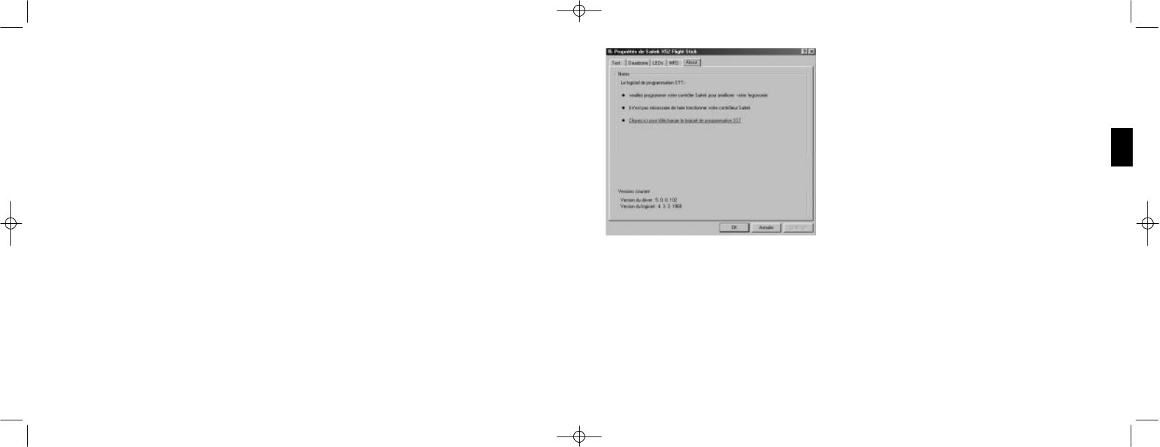
X52 manual(ok)(24/11/04) 2004.12.22 9:05 PM Page 48
Vous pouvez maintenant afficher l'heure actuelle dans les fuseaux horaires sŽlectionnŽs dans votre MFD. Voir Utilisation du MFD pour de.s informations plus dŽtaillŽes.
Gestion des rŽglages des dates
La date actuelle est affichŽe en bas ˆ droite de votre MFD. Vous pouvez rŽgler la fa•on dont la date est affichŽe. Vous prŽfŽrez peut-•tre voir le mois en premier, suivi du jour et de l'annŽe.
Pour changer les rŽglages de la date
1Cliquez sur l'onglet MFD.
Le format dans lequel la date est affichŽe sur votre MFD est indiquŽ dans le panneau Date Settings.
2 Pour cela, sŽlectionnez le format dans lequel vous dŽsirez afficher la date dans le menu dŽroulant correspondant.
3Cliquez sur OK.
Changer la fa•on dont votre bouton d'embrayage fonctionne
Le bouton d'embrayage sur votre manette des gaz est utilisŽ pour dŽsactiver temporairement les boutons dans le jeu en cours. Ceci vous permet de vŽrifier la fonction de chaque bouton ou touche sans interrompre la partie, et de sŽlectionner un profil diffŽrent si nŽcessaire. Pour plus d'information, voir Affichage des noms de boutons dans la partie Utilisation du MFD.
Pour changer la fa•on dont votre embrayage fonctionne, cochez ou non la case Bouton verrouillŽ d'embrayage dans le panneau Arrangements d'embrayage puis cliquez sur OK.
Une fois la case cochŽe, appuyez sur l'embrayage et rel‰chez-le pour dŽsactiver les boutons dans le jeu en cours. Pour rŽactiver les boutons, appuyez sur l'embrayage et rel‰chez-le ˆ nouveau.
Lorsque la case est vide, les boutons sont dŽsactivŽs dans le jeu tant que vous n'avez pas appuyŽ sur l'embrayage. Lorsque vous rel‰chez l'embrayage, le fait d'appuyez ˆ nouveau sur les boutons affecte la partie en cours.
Notes de visualisation et informations sur la version
Des informations utiles sur le logiciel de programmation SST sont fournies, ainsi qu'un lien vers le site Internet o• vous pourrez tŽlŽcharger la version la plus rŽcente du logiciel. Vous pourrez Žgalement visualiser les dŽtails des versions des pilotes et du logiciel que vous avez installŽ.
Pour visualiser ces informations, cliquez sur l'onglet About. Cet onglet est indiquŽ ci-dessous :
FRAN‚AIS
Utilisation du MFD
Le MFD (ou affichage multi-fonctions) fait partie intŽgrante de votre manette des gaz. Il affiche diffŽrentes informations, notamment le nom des boutons, le profil en cours d'utilisation et la date du jour. Il peut Žgalement fonctionner comme chronom•tre.
Vous pouvez changer certains rŽglages qui dŽterminent la fa•on dont votre MFD fonctionne. Par exemple, vous voudrez peut-•tre augmenter la luminositŽ de l'affichage, ou modifier l'affichage de la date. Pour cela, cliquez sur l'onglet MFD dans la fen•tre de propriŽtŽs Saitek X52 Flight Stick. Pour de plus amples informations, voir le chapitre intitulŽ Gestion des rŽglages du MFD dans la partie Gestion des rŽglages de votre contr™leur.
CaractŽristiques du MFD
Le MFD est divisŽ en trois parties :
¥La partie Mode, en haut du MFD, affiche le mode actuellement sŽlectionnŽ. Voir Travailler avec les modes, cidessous.
48 |
49 |
 Loading...