

Page 1

Workbook
Engine K Series 1.8 VVC
Rover Group are constantly seeking ways to improve the specification and design of its
vehicles and alterations take place continually.
Whilst every effort is made to produce up-to-date literature, this training workbook should
not be regarded as an infallible guide to current specification, nor does it constitute an
offer for the fitment of any particular system or component.
All rights reserved. no part of this Training Workbook may be reproduced without
prior permission of -
TECHNICAL ACADEMY
GAYDON TEST CENTRE
BANBURY ROAD
LIGHTHORNE
WARWICK
CV35 0RG
This Training Workbook is designed to support the Service Product Training courses and
is issued as part of the training programme.
It may be used to compliment other literature available but the Repair Operations Manual
should always be consulted prior to servicing or repair work.
© ROVER GROUP LIMITED - Nov 1997
Page 2

Page 3
ENGINE K SERIES 1.8 VVC
Technical Academy
01-34-RG-W-Ver:1 Page 1 of 28
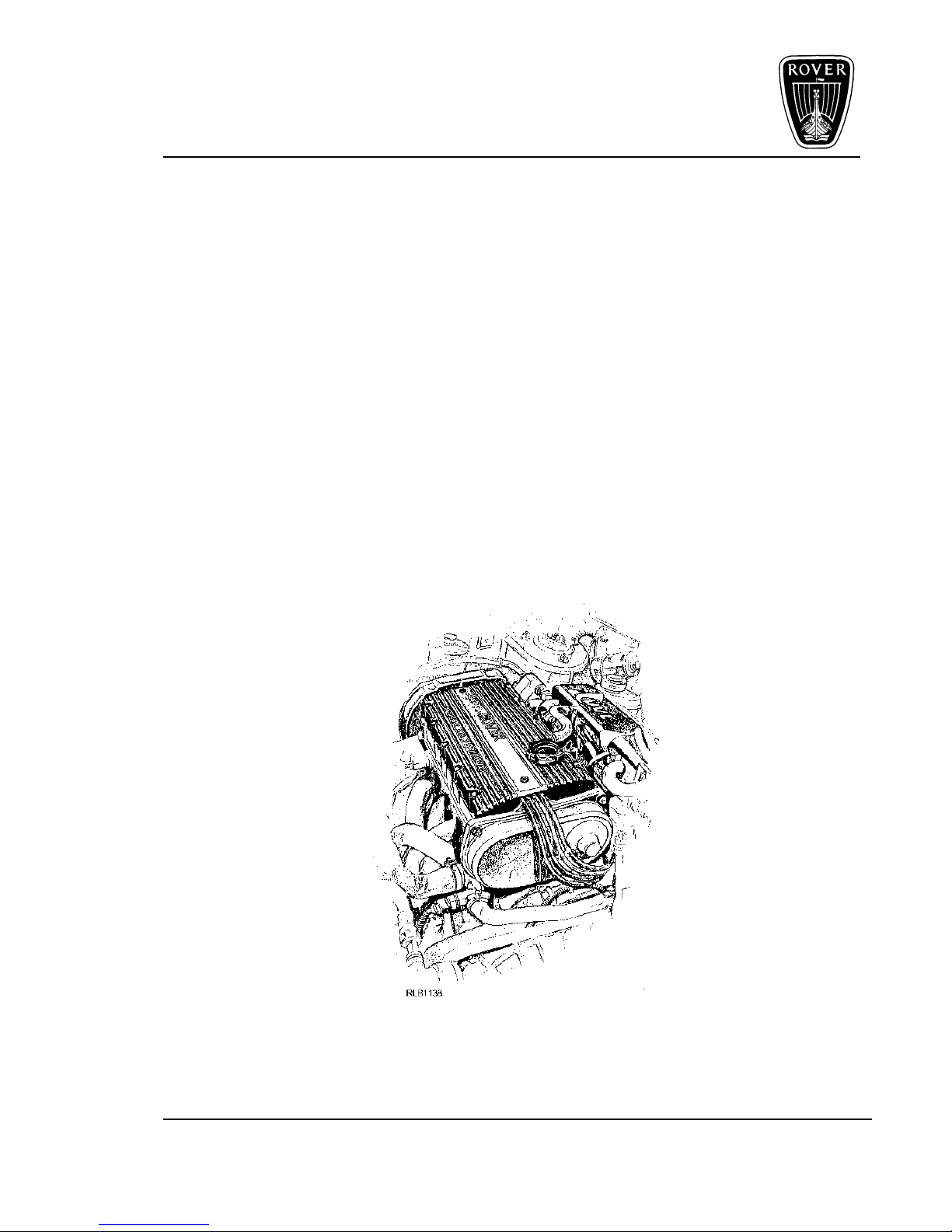
Variable Valve Control - VVC
Introduction
The 1.8 litre 16 valve ‘K’ Series engine with Variable Valve control, (VVC), is available in
the MG-F and the New Rover 200 series.
The 1.8 litre VVC engine also employs the MEMs 2J Engine Management System
The engine shares the key design features of the four cylinder ‘K’ Series engine, with the
ultra light, 'sandwich' construction of low pressure aluminium sand castings, held together
by high tensile through bolts for strength and low distortion.
The VVC engine also includes lightweight hydraulic tappets and lightweight pistons, giving
smoother running, particularly at higher engine speeds. The engine also includes 'damp
cylinder liners', first introduced to ‘K’ Series engines in 1995.
The main emphasis in this workbook is the overhaul procedure of the VVC cylinder head
with the aid of special tools.
To begin with, the following text will explain the operating principles of the VVC
mechanism.
Figure 1
Page 4
ENGINE K SERIES 1.8 VVC
Technical Academy
Page 2 of 28 01-34-RG-W-Ver:1
Variable Valve Control
Engine tuning is usually a compromise between low speed driveability and high speed power, and an increase in one is normally
accompanied by a reduction in the other The main reason for this
'trade off is a phenomenon called 'Inertial Ram Effect'.
The VVC overcomes these basic restraints by employing a
continuously variable camshaft profile; opening the intake valve for
longer periods at high engine speeds and shorter periods for more
sedate conditions to enhance bottom end torque and idle stability.
How VVC Works
The inlet camshaft, (and there are four of them), still receives drive
from the crankshaft in the normal manner; restricted to the overall
ratio of one camshaft revolution to every two from the crankshaft.
Working within this basic restraint, Rover engineers were able to
squeeze around 20% more power over the standard engine by
varying the speed of the camshaft within each revolution; slowing it
down whilst the valve is open to give a longer duration and speeding
it up to give a 'snap' open and close condition.
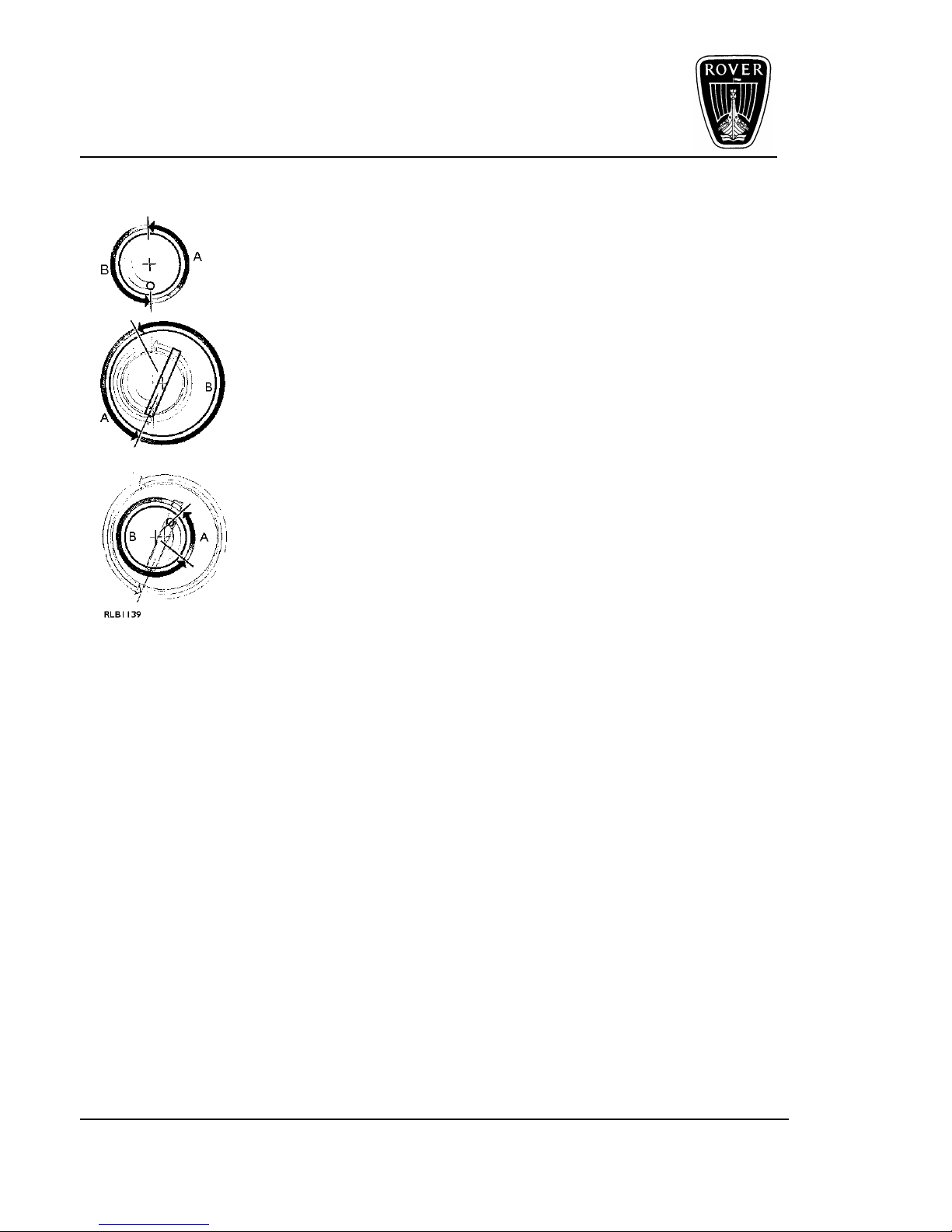
A = Distance covered in first half of rotation
B = Distance covered in second half of rotation
The principle of operation is extremely simple; driving through an eccentric mechanism
gives the necessary variation in velocity throughout the camshaft revolution.
Changes in the position of the eccentric in relation to the camshaft lobe, either speeds up,
or slows down the valve's opening sequence. Having the position of the eccentric
controlled through a hydraulic rack and pinion enables the MEMS 2J ECM to control
exactly the open period of each pair of intake valves.
Rotation of the Camshaft Drive
The inlet valve cam drive is turned at half crankshaft speed by a toothed drive belt.
Rotation of the Drive Ring
Because the drive ring centre is offset from the camshaft centre, the drive ring rotates
eccentrically and speeds up and slows down during its turn.
Rotation of the Cam Lobe
The slot on the drive ring engages the crank on the cam lobe and the eccentric rotation
becomes even more pronounced.
The basic principle is relatively easy to explain around one cylinder and one intake valve.
Figure 2
Page 5
ENGINE K SERIES 1.8 VVC
Technical Academy
01-34-RG-W-Ver:1 Page 3 of 28
Designing a working system for a 4 cylinder 16 valve engine was somewhat more
complex! Accepting that all four pairs of camshaft lobes are positioned differently to cope
with their unique role in the four stroke cycle, then each pair must be controlled with a
degree of independence.
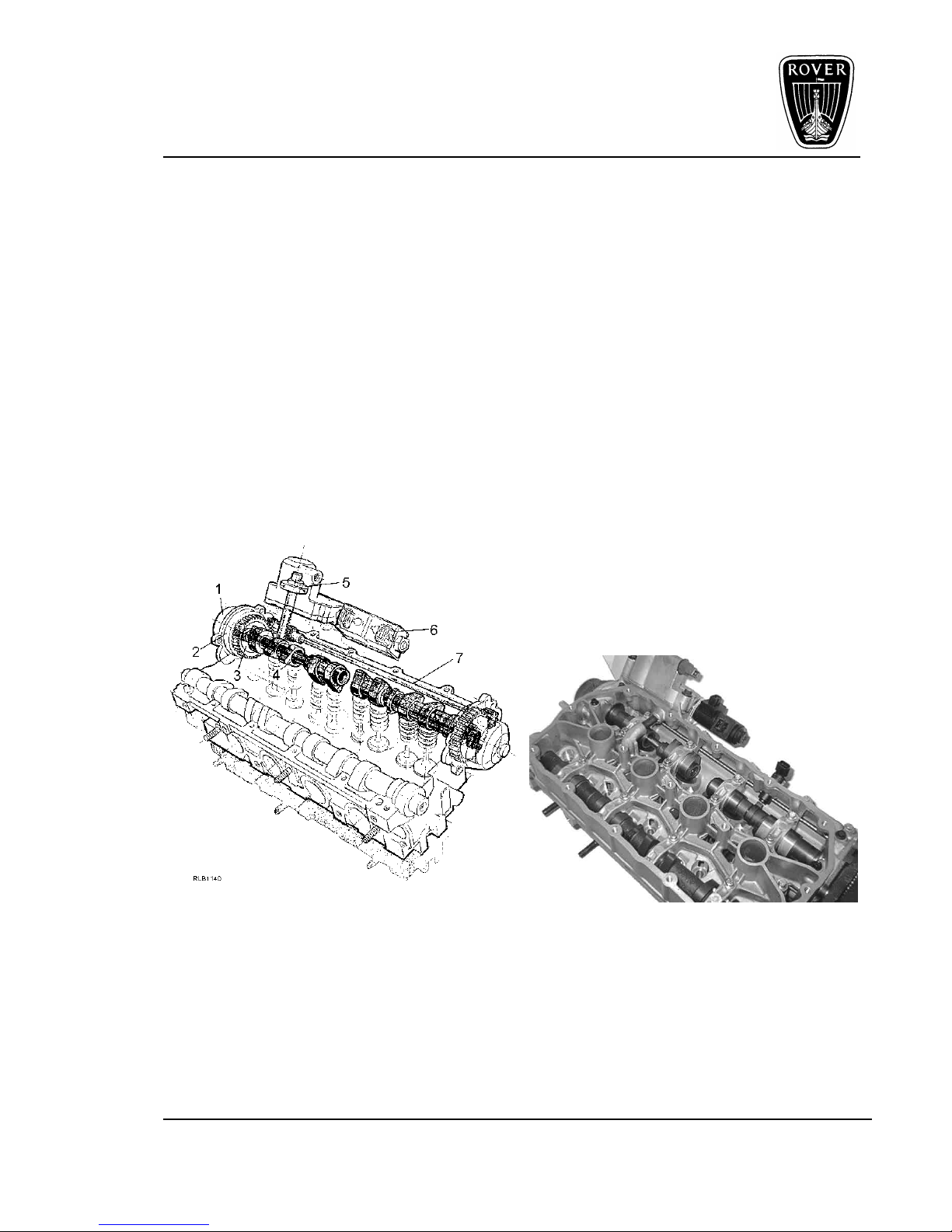
To achieve this, two VVC mechanisms are positioned either end of the cylinder head, each
controlling an inlet camshaft assembly; each of these assemblies drives two semiindependent camshafts, one for each pair of valves, making four inlet camshafts in all.
As there is no direct drive between the two inlet camshaft assemblies, an additional drive
belt is used, transmitting drive from the back of the exhaust camshaft to the rear inlet cam
assembly.
A control shaft is used to transmit drive to both VVC mechanisms, this is in turn controlled
by a hydraulic rack driven by the Hydraulic Control Unit (HCU), the position of which is
monitored and controlled by the MEMS 2J ECM through two solenoid valves and a
camshaft period sensor. The main ECM inputs for VVC are engine speed and load.
Figure 3
1. Camshaft drive 5. Piston
2. Control sleeve 6. HCU solenoids
3. Drive ring 7. Control shaft
4. Independent shaft
Page 6
ENGINE K SERIES 1.8 VVC
Technical Academy
Page 4 of 28 01-34-RG-W-Ver:1
VVC Technical Specifications
Type ‘K’ 1.8 VVC
Bore 80.0mm
Stroke 89.3mm
Capacity 1796cc
Compression ratio 10.5:1
Maximum power 147 PS @ 7000 rev/min.
Maximum torque 174 Nm @ 4500 rev/min.
Maximum rev/min 7300 rev/min.
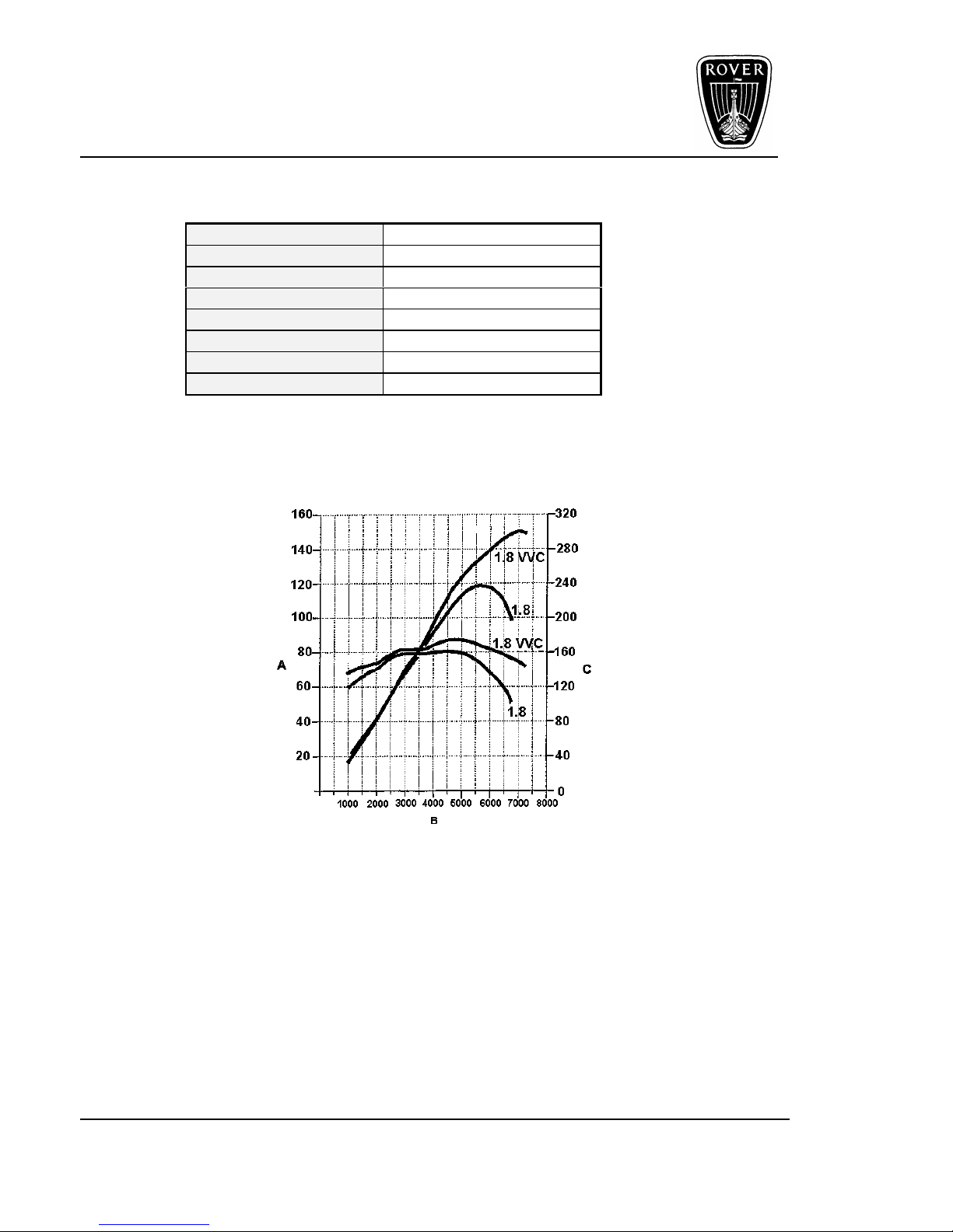
The following graph shows the power and torque comparison between the 1.8 litre 16
valve engine and the 1.8 litre 16 valve VVC engine.
Figure 4
A. Power (PS)
B. Engine speed (rpm)
C. Torque (Nm)
Page 7
ENGINE K SERIES 1.8 VVC
Technical Academy
01-34-RG-W-Ver:1 Page 5 of 28
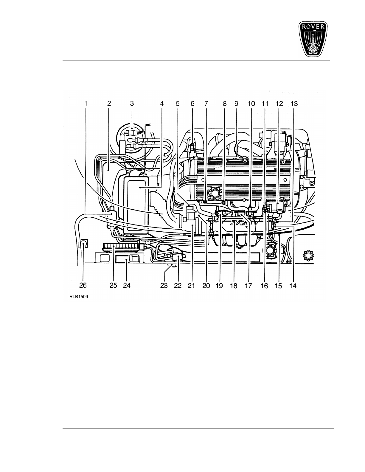
The following illustration shows the engine compartment components
for the 1.8 VVC MG-F.
Figure 5
1. Fuel filter 14. Manifold absolute pressure sensor
2. Resonator 15. Throttle cable
3. Fuel pump 16. Oil temperature sensor
4. Air filter 17. Ignition coil
5. Throttle position sensor 18. Fuel rail
6. Engine coolant temperature sensor 19. Idle air control valve
7. Intake air temperature sensor 20. Crankshaft position sensor
8. Camshaft position sensor 21. Throttle body
9. Oxygen sensor 22. Evaporative emission canister, purge valve
10. Injector (4 off) 23. Evaporative emission canister
11. Hydraulic control solenoids 24. Engine management relay module
12. Hydraulic control unit 25. Engine control module
13. Fuel pressure regulator 26. Inertia fuel shut-off switch
Page 8

ENGINE K SERIES 1.8 VVC
Technical Academy
Page 6 of 28 01-34-RG-W-Ver:1
The MEMS-2J, VVC Engine Control Module, (ECM), monitors all normal functions as with
other engines, but with the ‘variable valve control’, the ECM controls the inlet valve
opening and closing periods.
• The ECM measures the cam period via the camshaft sensor, and also controls the
VVC mechanism with two solenoids: one which increases the period and one which
reduces the period.
• The ECM also implements tune select which means that each ECM may contain
engine calibrations for one or more vehicles. In order to prevent an ECM being fitted to
a vehicle with the wrong calibration selected, when first supplied, the ECM has no
calibration selected therefore the engine will not run. When fitted to a vehicle, the ECM
calibration for that particular vehicle must be selected using ‘Test Book’ diagnostic
equipment in addition to programming the ECM security code.
This Training workbook relates to the Service repairs and adjustments the VVC cylinder
head.
Overhaul procedures and adjustments for the cylinder block, using the correct special tools
is the same for all 4 cylinder ‘K’ series engines.
Camshaft Timing Belt
NOTE: It is important that the camshaft drive belt adjustment is carried out when the
engine is ‘COLD’.
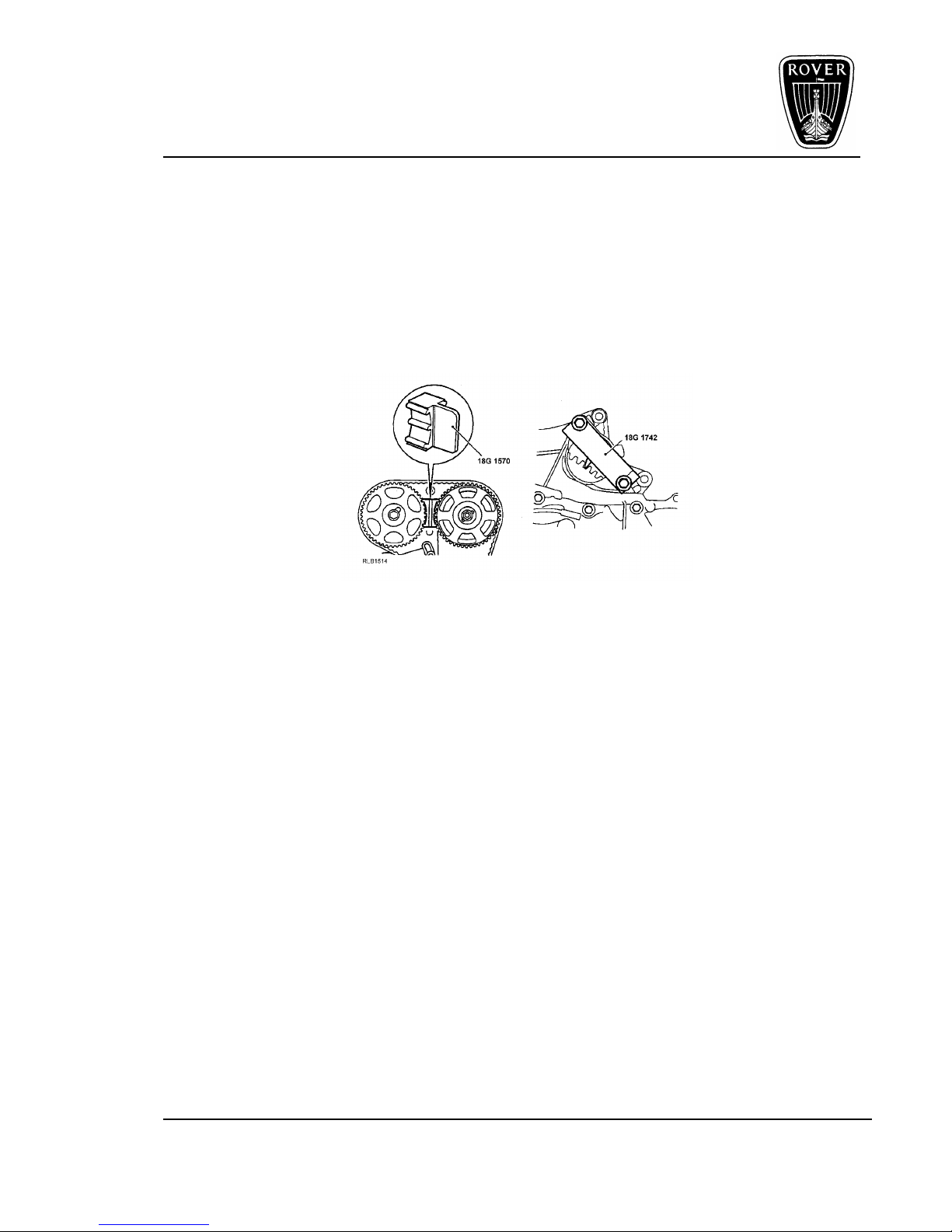
The front camshaft timing belt adjustment and replacement on the 1.8 VVC engine is
similar to any of the other 4 cylinder ‘K’ Series engines using the same special tool, 18G
1570 to lock the camshaft gears, and 18G 1742 to lock the crankshaft/flywheel from
turning, the latter fitted in the starter motor aperture.
NOTE: The front and rear camshaft drive belts are renewed at 60,000 miles (96,000km.)
The front timing belt is unique to the 1.8 VVC engine, and timing belts for standard ‘K’
engines must not be fitted. There are no routine adjustments recommended for the front
or rear camshaft drive belts.
• The timing belt is tensioned by special equipment at manufacture, eliminating the use
of a tensioner spring.
• A new timing belt for Service is supplied with the tensioner spring and pillar bolt.
• Inspection of the front and rear timing belts is by removing the top belt cover, (front),
and rear cover for the rear belt.
Check the timing belts for uneven wear, splitting or oil/water contamination.
If any of these faults are apparent, identify the cause of the fault and rectify,
then fit a new timing belt.
Page 9
ENGINE K SERIES 1.8 VVC
Technical Academy
01-34-RG-W-Ver:1 Page 7 of 28
New Timing Belt (front)
NOTE: When fitting a new timing belt, fit the spring pillar bolt and tensioner spring
supplied with the new belt. After tensioning the timing belt, remove the spring and
pillar bolt.
IMPORTANT: The tensioner spring without the rubber sleeve is unique to the VVC engine,
and has a higher spring loading. The tensioner spring, (with the rubber sleeve), is a
common fitment to all other four cylinder ‘K’ Series engines and must not be used on the
VVC engine.
Figure 6
Camshaft Drive Belt (Remove)
• With the upper timing belt cover removed, rotate crankshaft clockwise to align the
timing marks on the camshaft gears, and locate 18G 1570 between the gears.
• Always mark direction of rotation, (DOR), on the drive belt if it is to be reused.
• Release ½ turn, Allen bolt and tensioner backplate bolt, then move the tensioner down
to the fully off position, and retighten back plate bolt to 10Nm.
• Ease the timing belt from the gears using finger pressure only.
• Prevent the crankshaft from turning using 18G 1742, and undo and remove the
crankshaft pulley bolt, then remove lower timing belt cover.
Remove the timing belt from the engine.
Page 10

ENGINE K SERIES 1.8 VVC
Technical Academy
Page 8 of 28 01-34-RG-W-Ver:1
Camshaft Drive Belt (Refit)
• Ensure camshaft and crankshaft gears are clean and dry.
• Correctly align the timing marks on camshaft gears then fit 18G 1570 to retain the
camshaft gears in there correct position.
• Ensure that the timing mark is correctly aligned on the crankshaft gear.
• Position drive belt onto crankshaft gear then over camshaft gears, keeping the belt taut
from the crankshaft gear and between camshaft gears .
• Use finger pressure and ease drive belt over tensioner pulley and water pump gear,
making sure that the drive belt is central over all gears.
• Fit the lower belt cover noting correct alignment of rubber dust seal, and tighten cover
bolts to 5Nm.
• Fit crankshaft pulley, tightening the pulley bolt to 205Nm.
• Ensure that the tensioner Allen bolt and backplate bolt are loosened by ½ turn.
• Fit pillar bolt and tensioner spring.
• Remove 18G 1570 from camshaft gears.
• Rotate crankshaft 2 complete turns and realign the timing marks.
• Tighten tensioner backplate bolt to 10Nm, and Allen bolt to 45Nm.
• Remove tensioner spring and pillar bolt.
• Fit top drive belt cover.
Camshaft Rear Timing Belt
There is no adjustment procedure for the rear timing belt on the VVC engine.
If the belt has to be removed for any reason, then the following procedure should be
carried out.
Page 11

ENGINE K SERIES 1.8 VVC
Technical Academy
01-34-RG-W-Ver:1 Page 9 of 28
Removal
With the front timing belt cover removed, set the engine in its correct timed position,
inserting special tool 18G 1570 to lock the front camshaft gears.
• Using 18G 1521 to restrain the rear camshaft gear, loosen and remove both bolts
securing each camshaft gear.
• Mark D.O.R. on belt if it is to be re-used, and ease gears with belt from the camshafts.
Figure 7
Refit
• Make sure gear to camshaft mating faces are clean and dry.
• Fit inlet gear to camshaft and align the timing mark on the gear with the mark on the
backplate.
• Using finger pressure only, fit exhaust camshaft gear and timing belt together, ensuring
that the gear is correctly aligned with the dowel on the camshaft.
• Using a straight edge, check the alignment of the timing marks on the camshaft gears
with the mark on the backplate.
• Fit camshaft gear retaining bolts, then restrain gears from turning with 18G 1521 and
tighten bolts to 65Nm.
• Make sure the timing belt is positioned centrally around the gears, and re-check the
alignment marks using the straight edge.
• Remove 18G 1570 from the front camshaft gears and refit remaining components.
NOTE: The same torque setting, 65Nm, also applies to the front camshaft gear retaining
bolts.
Page 12

ENGINE K SERIES 1.8 VVC
Technical Academy
Page 10 of 28 01-34-RG-W-Ver:1
Camshaft Oil Seals
Front (Inlet)
With the camshaft drive belt and camshaft gears removed:
• Screw in gear retaining bolt to protect the threads in the camshaft.
• To remove the oil seal. screw in special tool 18G 1299A into the oil seal, tightening the
centre bolt of the special tool and extract the seal as shown.
• Remove the retaining bolt.
Figure 8
Refit
Thoroughly clean the sealing areas of the cylinder head and camshaft ensuring all traces
of rubber are removed.
NOTE: DO-NOT scrape or lubricate the sealing areas
• Carefully position the new oil seal onto the camshaft.
• Drift in new oil seal using 18G 1604 as shown making sure the seal is flush with the
face of the housing.
• Refit timing belt and gears.
NOTE: The same procedure applies when replacing the rear inlet camshaft oil seal.
Exhaust (rear)
Remove
The same special tool, 18G 1299A is used to remove the exhaust camshaft oil seal
adopting the same procedure as the inlet.
Refit
Carry out the same cleaning process, and DO NOT scrape or lubricate the sealing areas.
• Position the new seal onto the camshaft.
• Carefully drift in the seal using 18G 1587.
• Refit timing belt and gears.
Page 13

ENGINE K SERIES 1.8 VVC
Technical Academy
01-34-RG-W-Ver:1 Page 11 of 28
Figure 9
Cylinder Head
For the purpose of this Training Workbook, and the relevant notes that follow, the engine is
removed from the vehicle and is mounted on an engine stand in the workshop.
The full procedure for removing the cylinder head whilst fitted in the vehicle can be found
in the relevant Repair Manual.
The crankshaft pulley, front timing belt and camshaft gears will have to be removed from
the engine. This is to gain access to remove the timing belt rear cover and allows greater
manoeuvrability when lifting off and refitting the cylinder head.
• Disconnect all cooling, electrical and vacuum hoses making note of their fitted positions.
• Remove the plenum chamber, inlet and exhaust manifolds.
• Remove 2 screws securing the spark plug cover and remove cover, then disconnect
HT leads and release the HT leads from the rear camshaft belt cover.
• Progressively undo and remove the camshaft cover bolts, then remove cover.
NOTE: The gasket is reusable and should remain attached to the camshaft cover unless it
is to be renewed. Check the condition of the sealing path, it should be complete and
attached to the gasket.
• Progressively loosen and remove the cylinder head bolts in the sequence shown,
storing the bolts in their fitted order.
Page 14

ENGINE K SERIES 1.8 VVC
Technical Academy
Page 12 of 28 01-34-RG-W-Ver:1
Figure 10
• With assistance, lift off the cylinder head from the cylinder block.
CAUTION: Do not rotate the crankshaft with the cylinder head removed.
• Fit cylinder liner clamps 18G 1736, securing the clamps with cylinder head bolts as
shown ensuring that the bolts used are those originally fitted in that location.
Figure 11
Support the cylinder head on suitable wooden blocks on the workbench to prevent
damage to valves that are open and the cylinder head face.
• Progressively undo and remove the camshaft carrier bolts.
Page 15

ENGINE K SERIES 1.8 VVC
Technical Academy
01-34-RG-W-Ver:1 Page 13 of 28
Cylinder Head (Dismantle)
Camshaft End-float
Before removing the camshaft carrier, check the camshaft end-float.
This is done by fitting a suitable DTI to the camshaft carrier with the stylus contacting the
face of number 4 front inlet camshaft lobe as shown.
Figure 12
• Push the camshaft fully rearward and zero gauge, then move camshaft fully forward
and note gauge reading.
• Repeat the same procedure for the rear inlet camshaft with stylus contacting the face
of number 5 lobe.
• Check the end-float on the exhaust camshaft adopting the same procedure, positioning
the DTI on the front end of the camshaft.
Renew components as necessary to achieve the correct end-float.
Inlet Camshaft End-float:
0.03 to 0.15 mm
Service Limit = 0.25 mm.
Exhaust Camshaft End-float:
0.06 to 0.19mm
Service Limit = 0.3 mm.
Page 16

ENGINE K SERIES 1.8 VVC
Technical Academy
Page 14 of 28 01-34-RG-W-Ver:1
Camshaft Carrier (Remove)
With the rear belt cover removed, use 18G 1521 located in the rear inlet camshaft gear,
and rotate gear until the timing marks on both gears is facing outwards.
NOTE: With the timing marks in this position, the cam-lobes of number 3,4,5 and 6 on the
inlet camshafts should be facing upwards.
• Mark D.O.R. of rear belt if it is to be reused, restrain the camshaft gears using 18G
1521 and remove bolts and washers, and noting the fitted position of both gears as they
are different, then remove gears and belt.
• Remove the rear belt backplate, the camshaft sensor and the 3 bolts securing the
hydraulic control unit, (HCU), and withdraw the HCU from the cylinder head.
Figure 13
NOTE: Remove and discard the 2 labyrinth seals and the rack seal from the seal plate,
and also taking care not to damage the labyrinth seal retaining lugs on the seal
plate.
• Remove the oil seals from both VVC housings using the special tools as described in
the camshaft oil seal section.
• Remove and discard the 2 bolts securing the VVC housings to the cylinder head, then
slacken the 2 bolts 1 complete turn that secure the VVC housings to the camshaft
carrier.
• Progressively slacken, in the sequence, the camshaft carrier bolts noting the position of
the 4 longer bolts.
IMPORTANT: It is essential that during the following operations that both inlet camshafts
are retained in their respective VVC assemblies. If the camshafts are removed from the
VVC housing then the complete assembly must be replaced.
Page 17

ENGINE K SERIES 1.8 VVC
Technical Academy
01-34-RG-W-Ver:1 Page 15 of 28
• Carefully release the camshaft carrier from the cylinder head, then lift the carrier from
the cylinder head complete with the VVC assemblies.
• Ensure that both inlet camshafts are retained in the carrier, then invert the assembly
• Slacken, but do not remove the 2 bolts securing the VVC housings to the carrier.
IMPORTANT: Sufficiently slacken the 2 bolts to enable the timing plates 18G 1770/1 and
18G 1770/2 to be fitted.
Figure 14
• Fit timing plates 18G 1770/1 to front and 18G 1770/2 to rear VVC assemblies, then fit
clamps 18G 1770, to both assemblies, securing the clamps with the camshaft gear
retaining bolts and washers.
CAUTION: Identify each VVC assembly in its fitted position an DO NOT attempt to
interchange the front and rear assemblies.
• Remove the 2 VVC housing bolts to the carrier, then carefully remove both camshafts
together with the VVC assemblies, but DO NOT remove clamps 18G 1770.
NOTE: Keep the 2 VVC housing bolts to carrier at this stage for assembly purposes.
New ‘Patchlock’ bolts will be fitted on final assembly.
• Remove the control shaft from the carrier and lift out the exhaust camshaft from the
cylinder head, then using a stick magnet, remove the hydraulic tappets keeping them in
their fitted order and inverted to prevent oil loss.
Page 18

ENGINE K SERIES 1.8 VVC
Technical Academy
Page 16 of 28 01-34-RG-W-Ver:1
Hydraulic Tappets
Check the tappets for signs of wear, scoring and overheating, and ensure oil drilling in
each tappet is free of restrictions.
Figure 15
CAUTION: The hydraulic tappets fitted to the VVC engine are lighter than those fitted to
non-VVC engines, and are similar in appearance to the earlier type tappets, (A), as
shown.
It is essential that these early tappets are not fitted to VVC engines, and to ensure that the
correct replace tappet is fitted, measure the overall length of the tappet.
Tappet outside dia. - (All Engines) = 32.959 to 32.975 mm
Early tappet - (Length) Non-VVC engines = 26.0 mm
Later tappet - (Length) VVC engines = 24.5 mm
Camshafts (Inlet)
Inspection of the inlet camshafts on the VVC engine is the same as other ‘K’ series
engines except that the clamps, 18G 1770 MUST-NOT be removed from the VVC
assembly.
Inlet camshafts and VVC mechanisms are supplied as complete assemblies.
The inlet and exhaust camshaft bearing radial clearances can be checked using
Plastigage.
• Clean camshaft carrier and cylinder head bearing surfaces using a suitable solvent to
soften the old sealant, and then remove it with the plastic scraper supplied in the
sealant kit.
• Fit exhaust camshaft into cylinder head and place a piece of Plastigage across each
bearing journal.
• Install both VVC assemblies, with special tools fitted to the camshaft carrier and retain
in position as shown in figure 17 with a slave M6 bolt, then remove the clamps 18G
1770.
Page 19

ENGINE K SERIES 1.8 VVC
Technical Academy
01-34-RG-W-Ver:1 Page 17 of 28
Figure 16
• Place a strip of Plastigage across each inlet camshaft journal, then carefully fit the
carrier to the cylinder head, securing the carrier with the 32 bolts, (4 longer bolts at each
end of carrier), and tighten in the sequence shown to 10Nm.
Figure 17
CAUTION: DO NOT rotate camshafts.
• Progressively slacken and remove bolts, then carefully remove camshaft carrier and
VVC assembly from the cylinder head ensuring that both inlet camshaft assemblies are
retained in their respective VVC assemblies, and the exhaust camshaft remains in the
cylinder head.
• Invert the carrier assembly and measure the widest portion of Plastigage on each inlet
camshaft journal and record measurement.
Inlet camshaft Exhaust camshaft
Figure 18
Page 20

ENGINE K SERIES 1.8 VVC
Technical Academy
Page 18 of 28 01-34-RG-W-Ver:1
NOTE: There are 2 different size journals on the inlet camshafts, 25mm and 40mm with
different radial clearances.
Inlet Camshaft Journal Clearances
25mm dia, = 0.025 to 0.060mm
Service limit = 0.1mm
40mm dia. = 0.030 to 0.070mm
Service limit = 0.1mm
Exhaust Camshaft
Journal Clearance = 0.060 to 0.094mm
Service limit = 0.15mm
If the bearing clearances on any camshaft journals is excessive, fit new inlet camshafts
with VVC assemblies and repeat process. If clearances are still excessive, renew cylinder
head and carrier assembly.
Figure 19
• Refit 18G 1770 clamps to both inlet camshafts and VVC assemblies, retaining the
clamps in position with camshaft gear bolts and washers.
• Remove the slave bolts securing the VVC assemblies to the carrier, then carefully
remove both assemblies from the carrier.
NOTE: If new VVC housing gaskets have been fitted, DO NOT remove the timing plates
18G 1770/1 and 18G 1770/2
• Remove the exhaust camshaft from the cylinder head
• Clean all traces of Plastigage using an oily cloth.
Page 21

ENGINE K SERIES 1.8 VVC
Technical Academy
01-34-RG-W-Ver:1 Page 19 of 28
VVC Housing Gaskets
To replace the VVC housing gasket, one to each VVC assembly, lightly secure the front
VVC housing and camshaft in a soft-jawed vice with the camshaft positioned upwards as
shown.
Figure 20
• Remove 18G 1770 clamp and 18G 1770/1 timing plate, taking care not to allow the
camshaft becoming separated from the VVC mechanism.
• Remove and discard old gasket.
• Prior to fitting new gasket, apply a light film of grease to the gasket face of the VVC
housing, this assists keeping the gasket in its correct location.
• Lubricate sealing ring of gasket with engine oil.
• Fit 18G 1770/1 timing plate to housing, then fit the gasket aligning the bolt holes.
• Assemble 18G 1770 clamp to the camshaft and VVC assembly, retaining the clamp
with gear bolt and washer, then remove the assembly from the vice.
Carry out the same procedure for the rear VVC assembly.
Timing Gears
Clean timing gears, check gear teeth for damage and drive pin slot for wear and replace
as necessary.
CAUTION: If the gears have been subjected to prolonged exposure to oil contamination,
soak gears in a solvent bath, then thoroughly wash in clean solvent
All remaining cylinder head re-work is the same as 1.4 and 1.6 ‘K’ Series engines:
• Valves and springs are removed using 18G 1519 spring compressor and 18G 1519/1
adapter.
• Valve stem oil seals are removed/replaced using 18G 1577.
• Valve guides are removed/replaced using 18G 1576A.
• Use a suitable straight edge to check cylinder head face for warpage
Page 22

ENGINE K SERIES 1.8 VVC
Technical Academy
Page 20 of 28 01-34-RG-W-Ver:1
VVC Cylinder Head Data
Maximum warp 0.05mm
Cylinder head height: (New) 118.95 to 119.05mm
Reface limit 0.20mm
Valve spring colour code Blue
Valve spring free-length 47.6mm
Valve seat angle 45º
Valve seat width 1.5mm
Valve stem fitted height 38.93 to 39.84mm
Full information on cylinder head re-work, i.e., valve guide replacement, valve seat
refacing and the renewal of valve seat inserts can be found in the ‘K’ Series Engine
Overhaul Manual.
Hydraulic Control Unit (HCU)
If necessary, the HCU can be dismantled to check the condition of the piston and spool
valve bores for scoring or corrosion and the renewal of ‘O’ rings.
To dismantle the HCU, identify each solenoid to its fitted position, noting its angle at which
it is positioned relative to the HCU.
• With the sleeve bolt removed, remove outer solenoid and then the inner solenoid.
• Next, remove the spool valve, then the oil temperature transmitter, followed by
withdrawing the piston and rack assembly.
IMPORTANT: Always renew the ‘O’ ring seals.
Figure 21
• Undo and remove the screw securing the piston to the rack.
• Ease the piston from the rack, then carefully remove the piston seal, taking care not to
damage the machined edges of the piston seal groove.
Page 23

ENGINE K SERIES 1.8 VVC
Technical Academy
01-34-RG-W-Ver:1 Page 21 of 28
Figure 22
Thoroughly inspect all components:
• Piston bore and spool valve bore for scoring or corrosion. If heavy scoring or corrosion
is apparent, the HCU will have to be replaced.
NOTE: Light scoring and corrosion may be removed using 600 grade wet or dry paper,
soaking the paper in engine oil for at least 30 minutes.
• Check the piston for scores and rack teeth for wear, replacing the HCU if either are
evident.
• Check the control shaft gear teeth for wear or chipped teeth and renew if either are
evident
• Make sure the oil drillings in the spool valve are clear of restrictions.
Prior to reassembly of the HCU, thoroughly clean all components and dry with compressed
air.
• Lubricate new labrynth seals with engine oil, then using fingers only, fit seals to each
side of the seal plate, making sure the seals are located beneath the retaining lugs.
Figure 23
Page 24

ENGINE K SERIES 1.8 VVC
Technical Academy
Page 22 of 28 01-34-RG-W-Ver:1
• Fit new rack seal to plate, then slide rack through the seal.
• Using fingers only, lubricate and fit new seal to piston, then secure the rack in the soft-
jawed vice and fit piston to rack securing it with its screw.
Figure 24
• Lubricate piston bore with engine oil, then position the seal plate, piston and rack
assembly to the HCU with the rack teeth facing towards the fixing hole which is adjacent
to the solenoid side of the unit.
• Enter piston assembly into bore at an angle to the cut-out in the bore to prevent damage
to piston seal.
• Lubricate 3 new ‘O’ rings with engine oil and fit to the spool valve porting grooves.
• Lubricate new ‘O’ rings and fit to the spool valve
nut side of the inner solenoid, and washer and
bolt side of the outer solenoid.
• Fit spool valve into HCU, twisting the valve
slightly as it is inserted into the bore to avoid
damaging the ‘O’ rings, then tighten spool valve
nut to 26Nm.
• Position inner solenoid on spool valve with the
lettering on the end of the solenoid facing away
from the control unit, then fit washer and new ‘O’
ring .
• Position outer solenoid on spool valve, also with
lettering on the end of solenoid facing away from
the control unit.
• Position both solenoids as shown in figure 26,
then fit and tighten sleeve bolt to 6Nm
CAUTION: DO NOT exceed the specified torque, and do not fit oil temperature transmitter
at this stage, but plug the port in the HCU to prevent dirt ingress. It may also be necessary
to re-position the solenoids to clear breather pipes when the engine is fitted to vehicle.
Figure 25
Page 25

ENGINE K SERIES 1.8 VVC
Technical Academy
01-34-RG-W-Ver:1 Page 23 of 28
Cylinder Head Reassemble
• Lubricate the exhaust cam lobes and journals with engine oil, and position camshaft in
cylinder head, then lubricate the inlet camshafts and control shaft.
• Position the control shaft into the carrier making sure the shaft is fully seated in its
journals and the centre of the slot in the shaft is aligned with the cylinder head mating
surface of the carrier.
• Carefully position front and rear cams and VVC assemblies into the carrier at the same
time engaging the gear teeth of the control shaft in the VVC assemblies.
Figure 26
• Make sure that the holes in the VVC housings are aligned with the bolt holes in the
carrier, that the centre of slot in control shaft is still aligned with the carrier to cylinder
head mating surfaces, and timing plates 18G 1770/1, (front), and 18G 1770/2, (rear) are
correctly located in the control sleeves, and with the control shaft fully seated in its
journals.
NOTE: If the bolt holes are not aligned or the slot in the control shaft has moved, reposition VVC assemblies and shaft as necessary until alignment is correct.
• Fit and finger tight slave bolts, (new ‘Patchlock’ bolts will be fitted at final assembly), to
retain both VVC assemblies to the carrier, then remove 18G 1770 clamps, but DO-NOT
remove timing plates at this stage or damage to VVC housing seals will result.
• Apply continuous, thin beads of sealant, (Hylomar 2000), to the paths on the cylinder
head as shown in figure 28, then spread to an even film using a brush or roller.
Page 26

ENGINE K SERIES 1.8 VVC
Technical Academy
Page 24 of 28 01-34-RG-W-Ver:1
Figure 27
CAUTION: Make sure that the sealant is kept clear of oil feed drillings, oil grooves and
control shaft journals and that assembly is completed within 20 minutes.
It is also essential that during the following operations to ensure that the front and rear inlet
camshafts are retained in the camshaft carrier and their respective VVC assemblies, and
also taking great care not to rotate the camshafts or control shaft.
• Invert the carrier assembly and fit to cylinder head, screwing in the 32 bolts, (4 long
bolts at each end of carrier), then using the sequence shown in figure 28, progressively
tighten bolts to 10Nm.
• Replace the slave bolts, one bolt at a time, retaining the VVC housings to the carrier
with new ‘Patchlock’ bolts.
• Remove the timing plates from both VVC assemblies, then tighten the 2 bolts retaining
the VVC housings to the carrier to 10Nm, then fit new ‘Patchlock’ bolts, VVC housings
to cylinder head and tighten to the same torque, 10Nm.
The next stage is to fit the camshaft and VVC housing oil seals.
Figure 28
• Lubricate seal running areas at the front and rear of the exhaust camshaft, then fit new
seals using 18G 1587, then fit new seals to both VVC housings using 18G 1604,
making sure that the seals are fitted flush with the face of the VVC housings.
• Fit the rear timing belt backplate to cylinder head and tighten bolts to 6Nm (M5 bolts),
and 10Nm (M6 bolts).
The next stage is to fit the HCU to the camshaft carrier.
Page 27

ENGINE K SERIES 1.8 VVC
Technical Academy
01-34-RG-W-Ver:1 Page 25 of 28
• Make sure the piston is pushed fully to the top of the bore and that the rack teeth are
aligned to the control shaft teeth, positioning the HCU and seal plate to the camshaft
carrier, and making sure that the rack and control shaft teeth are engaged, then fit and
finger tight the 3 bolts.
Figure 29
• Check that the timing slots in front and rear VVC control sleeves are visible through the
holes in the camshaft carrier as shown in figure 30.
NOTE: If the timing slots are not visible, remove the HCU and carry out the following;
Figure 30
• Using a screwdriver, rotate the control shaft as far as possible in an anti-clockwise
direction, figure 31, as viewed from the front of the carrier, noting that the slots should
be visible in both VVC control sleeves.
• Push the piston to the top of the bore, then refit the HCU to the carrier, screwing in the 3
bolts finger tight and recheck that the slots are now visible. If the slots are still not
visible, repeat the procedure again.
• Apply low pressure air to the oil temperature transmitter port to fully extend the rack.
• Visually check that the rack is fully extended and the timing slots are no longer visible
through the inspection holes in the carrier, then tighten the 3 bolts to 25Nm.
Page 28

ENGINE K SERIES 1.8 VVC
Technical Academy
Page 26 of 28 01-34-RG-W-Ver:1
• Fit new washer and oil temperature transmitter, then lubricate new ‘O’ ring with engine
oil and fit to camshaft sensor, install sensor to carrier and secure with bolt tightening
bolt to 5Nm.
The next stage of the operation is to fit the rear timing gears and drive belt, where 18G
1521 holding tool and a suitable straight edge are required.
Figure 31
• Fit the rear inlet and exhaust timing gears leaving the bolts finger tight, then using 18G
1521, rotate each timing gear until the timing marks are facing outwards.
• Using the straight edge, check the alignment of each timing mark on the gears with the
embossed line on the timing cover backplate.
Note: With the timing marks in this position, the inlet cam lobes of numbers 3,4,5 and 6
will be facing upwards.
• Remove the inlet camshaft gear sufficiently to enable the
rear timing belt to be fitted, making sure that the DOR
mark is facing the correct way, then refit the gear, bolt and
washer, restraining each gear with 18G 1521 and tighten
the bolts to 65Nm.
• Temporarily fit the front timing gears to their respective
camshafts, as shown in figure 33, then rotating the gears
with 18G 1521 to align the timing marks, inserting 18G
1570 to hold gears in position.
• Using the straight edge, recheck the timing mark
alignment on the front and rear pairs of gears, then
remove 18G 1570 and the front timing gears.
• Fit the rear timing belt cover, tightening the cover bolts to
10Nm.
Figure 32
Page 29

ENGINE K SERIES 1.8 VVC
Technical Academy
01-34-RG-W-Ver:1 Page 27 of 28
Cylinder Head - Refit
If the crankshaft has been rotated, make sure that the timing mark on the crankshaft timing
gear is aligned with the flange on the oil pump housing, and that 18G 1571 is locking the
flywheel.
• Remove cylinder liner clamps, 18G 1736, and remember, DO-NOT rotate crankshaft
• Make sure the 2 locating dowels are fitted in the cylinder block, then apply engine oil to
cylinder head bolts, under heads and to the threads.
• Fit new cylinder head gasket, (DRY), onto cylinder block with identification marks facing
upwards taking care not to damage the sealing faces of gasket.
• With assistance, fit cylinder head to block carefully locating the dowels, then carefully
enter cylinder head bolts in their original fitted locations; DO NOT DROP into threads,
and screw in finger tight.
Figure 33
• Progressively tighten the bolts in the sequence shown to 20Nm, then using a felt tip pen
mark position of radial mark on each bolt head.
• Tighten bolts in the same sequence through 180º followed by a further 180º in
sequence aligning the marks.
CAUTION: If any bolt is overtightened, back off 90º and re-align to the mark.
• Clean the mating surfaces and inside of camshaft cover and if necessary, wash oil
separator elements in solvent and blow-dry.
• Fit new camshaft cover gasket to the carrier with either the ‘TOP’ mark towards the inlet
manifold or ‘EXHAUST MAN. SIDE’ towards the exhaust manifold.
• Fit the cover to carrier and tighten the bolts in the sequence shown to 10Nm.
Page 30

ENGINE K SERIES 1.8 VVC
Technical Academy
Page 28 of 28 01-34-RG-W-Ver:1
• Fit the front belt upper rear cover and tighten bolts
to 10Nm, then fit camshaft gears to their respective
camshafts making sure that the camshaft drive
gear pins, figure 33, are located in the correct slot
in the gears, retaining gears with 18G 1521, and
tighten bolts to 65Nm:
• Using 18G 1521, turn the camshaft gears to align
the timing marks as shown in inset, figure 36, then
insert 18G 1570 to retain gears in position.
• Fit timing belt tensioner, pillar bolt and spring.
• Fit timing belt following the correct procedure as in the timing belt section of this
workbook.
Cylinder Block Assembly
The cylinder block design features that accommodates the VVC cylinder head is similar to
all 4 cylinder ‘K’ Series engines.
These are:
• ‘Damp’ cylinder liners.
• Lightweight aluminium alloy, thermal expansion
pistons, (VVC only), are supplied complete with
connecting rods, and are available in two grades, A
and B.
• Main and big-end bearing diametric clearances are
controlled by three grades of selective bearing shells.
• The five bearing, eight balance weight crankshaft has
its end-float controlled by thrust washer halves
positioned in the cylinder block at the centre main
bearing location.
• An aluminium alloy sump forms the lubrication
reservoir, and is sealed to the bearing ladder with
‘Hylomar 2000’.
NOTE: All existing ‘K’ Series engine special tools are used and full details of the cylinder
block overhaul and data is available in the ‘K’ series Engine Overhaul Manual.
Figure 34
Figure 35
 Loading...