

Page 1
TAB 900TAB 900
TAB 900TAB 900
HDHD
HDHD
www.roverinstruments.com
& TAB 900 Plus& TAB 900 Plus
& TAB 900 Plus& TAB 900 Plus
TFT 16:10TFT 16:10
USER’S GUIDE
Page 2
2
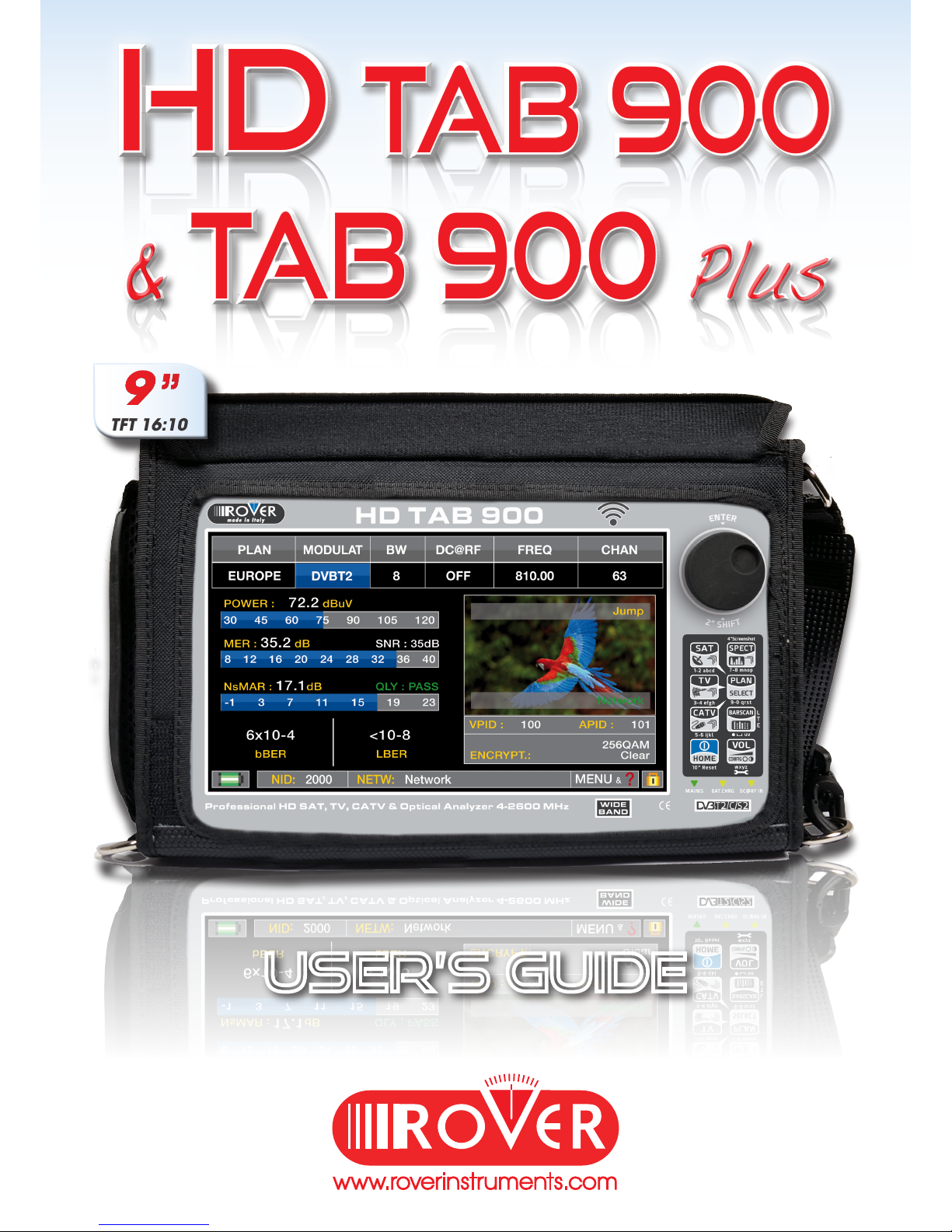
GET TO KNOW YOUR TAB 900
FRONT PANEL __________________________________
• WHEEL
• POWER
To turn on
press the
‘HOME’ key.
To turn off
press and hold
the ‘HOME’ key
Use the wheel to navigate across the screen and adjust the values
• RESET HARDWARE • RESET SOFTWARE
+
With instrument ON,
Keep the “HOME” key
pressed for 10” and
turn on again.
From instrument OFF, Switch
on the meter, immediately
after keep the “VOLUME” key
pressed until a beep is heard.
Rotate to select
a menu item
or to change
a value
Press to select a
menu item or a
numeric field,
Select a menu
item, press and
hold 2” to display
the pop-up menu.
NB: The MENU (functions and Graphics) an be change without advise.
Page 3
3
7
8
9 10
4
5
2
1
3
6
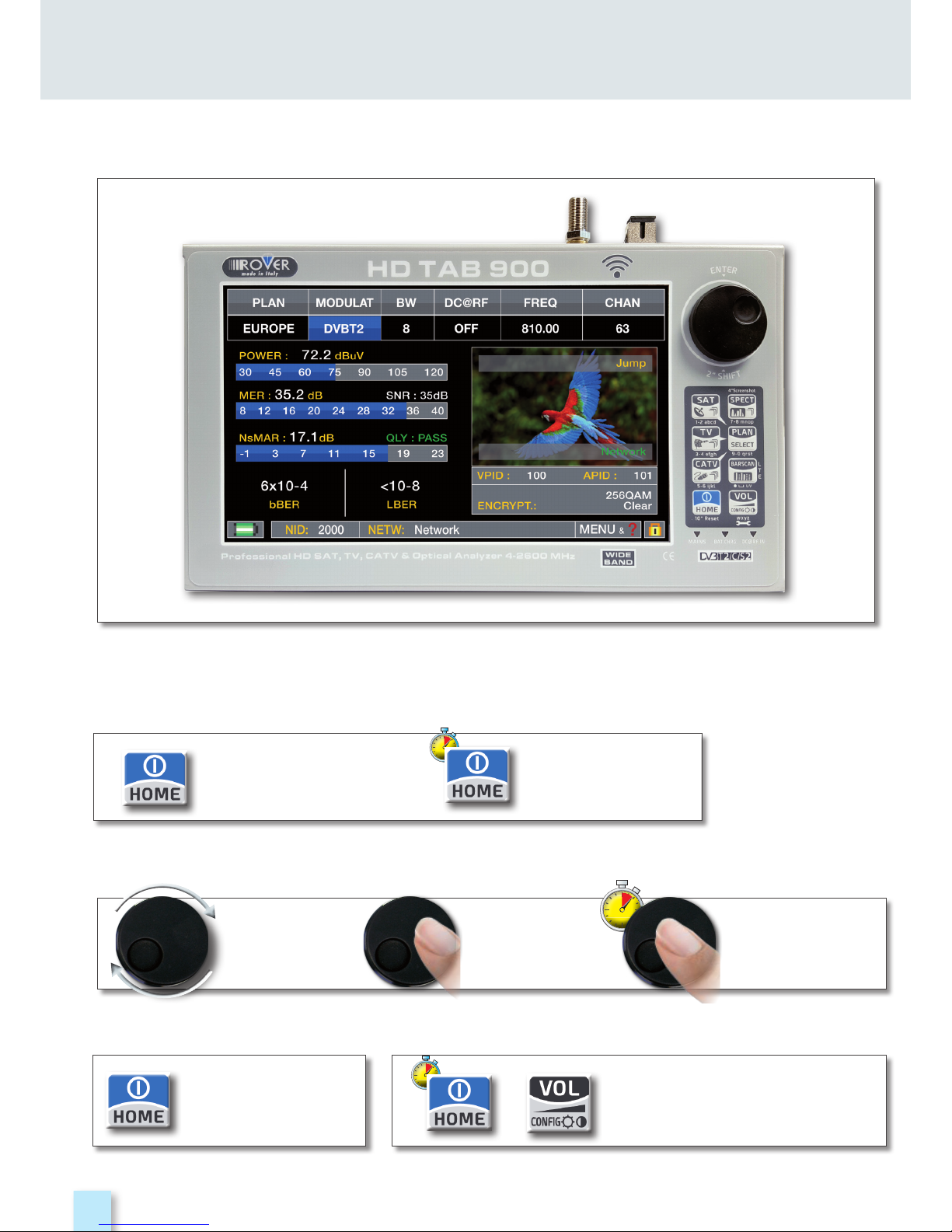
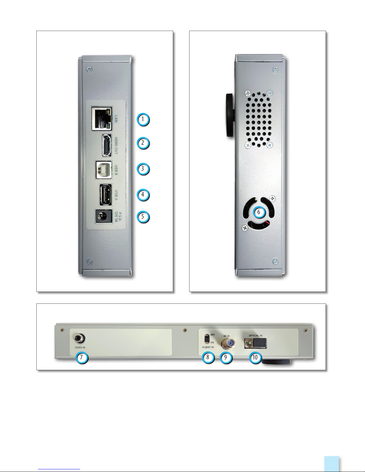
• LEFT SIDE
• TOP SIDE
• RIGHT SIDE
1. = LAN Eternet RJ45
2. = HDMI Output
3. = USB B SW upgrades
4. = USB A memory stick
5. = Power Supply input (12 V DC - 2A)
6. = Fan
7. = Analog video IN (CVBS)
8. = Remote Power Supply switch
DC at RF IN ON/OFF
9. = IF/RF IN “F” 75 Ω
10. = OPTIC IN: SC opt.
SIDE PANELS
____________________________________________________
Page 4
4
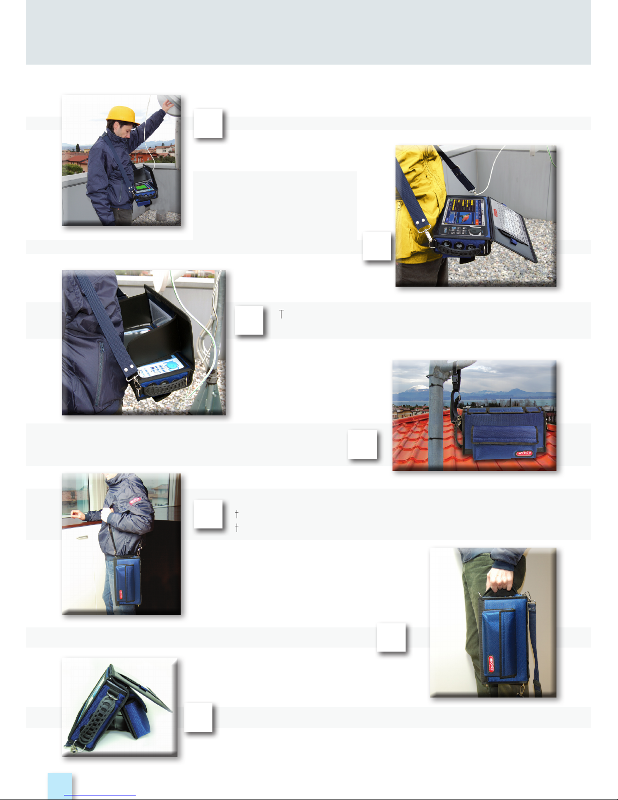
Make work easier by taking advantage of your multi-purpose bag.
Work safely and without restrictions with both hands free.
The sunlight shield flap allows improved visibility
of the high brightness display.
Secure your meter by connecting it to the
antenna mast or in your car using the practical
ring belt with quick attachment.
If you change the configuration of
the shoulder strap, you can easily carry
the meter vertically by your side.
carry your instrument using its practical handle.
1
3
4
5
6
7
MULTI-PURPOSE BAG
You can use the bag’s convenient stand flap for operation on a counter.
Connect the shoulder
strap to the two hooks at the
corners of the bag (top left
and bottom right), so you can
hang your meter around your
neck leaving both hands free.
2
Page 5
5
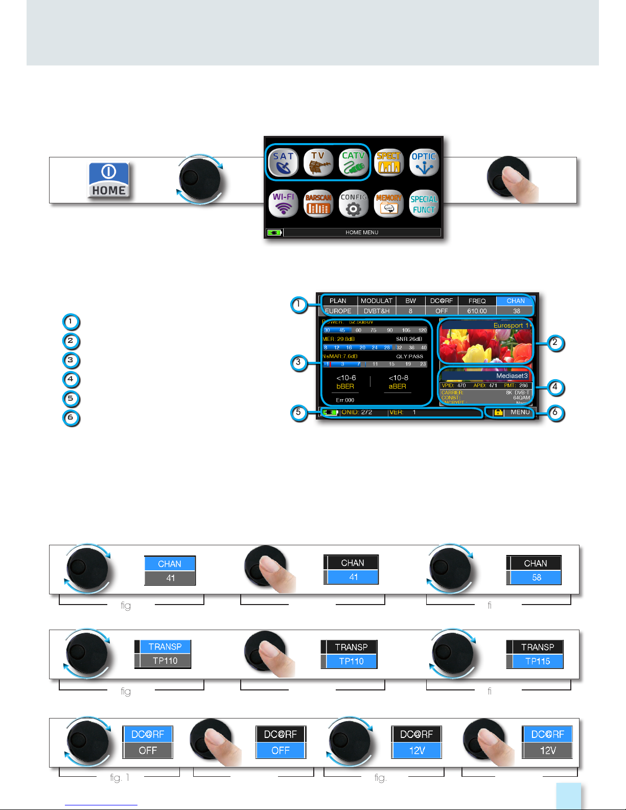
HOME AND NAVIGATION
Press the ‘HOME’ key to go to the home screen, then rotate the wheel to navigate on ‘SAT’,
‘TV’ or ‘CATV’ icons and press the wheel to select the measurement mode required.
‘HOME’ SCREEN
________________________________________________
Press the ‘HOME’ key at any time to
return to the home screen
NAVIGATION
____________________________________________________
Use the touch screen and the wheel to navigate across the screen and to change values
DISPLAY ZONES
1
tuning parameters
2
live picture
3
measurements
4
channel info
5
transport stream info
6
context sensitive menu
How to select from the menus and adjust the value:
• Rotate the wheel and select from the menu required (fig. 1)
• Press the wheel (fig. 2)
• Rotate the wheel to adjust the value (fig. 3)
• Press the wheel and confirm the selection (fig. 4)
NAVIGATION USING MECHANICAL COMMANDS
Example of TV/CATV channel selection:
fig. 1
fig. 1
fig. 1 fig. 3fig. 2 fig. 4
fig. 2
fig. 2
fig. 3
fig. 3
Example of SATELLITE transponder selection (TP/TS):
Example of remote TV-CATV power supply selection (DC&RF):
2
4
6
1
5
3
Page 6
6
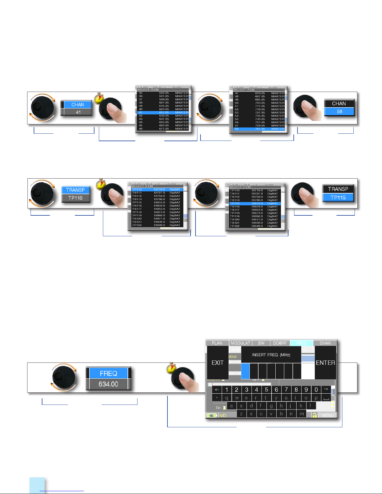
How to select from the menus and change a value using the drop down menus:
• Rotate the wheel and select the menu required (fig. 1)
• Keep the wheel pressed for 2” to visualized the drop down menu (fig. 2)
• Rotate the wheel to adjust the value (fig. 3)
• Press the wheel and confirm the selection (fig. 4)
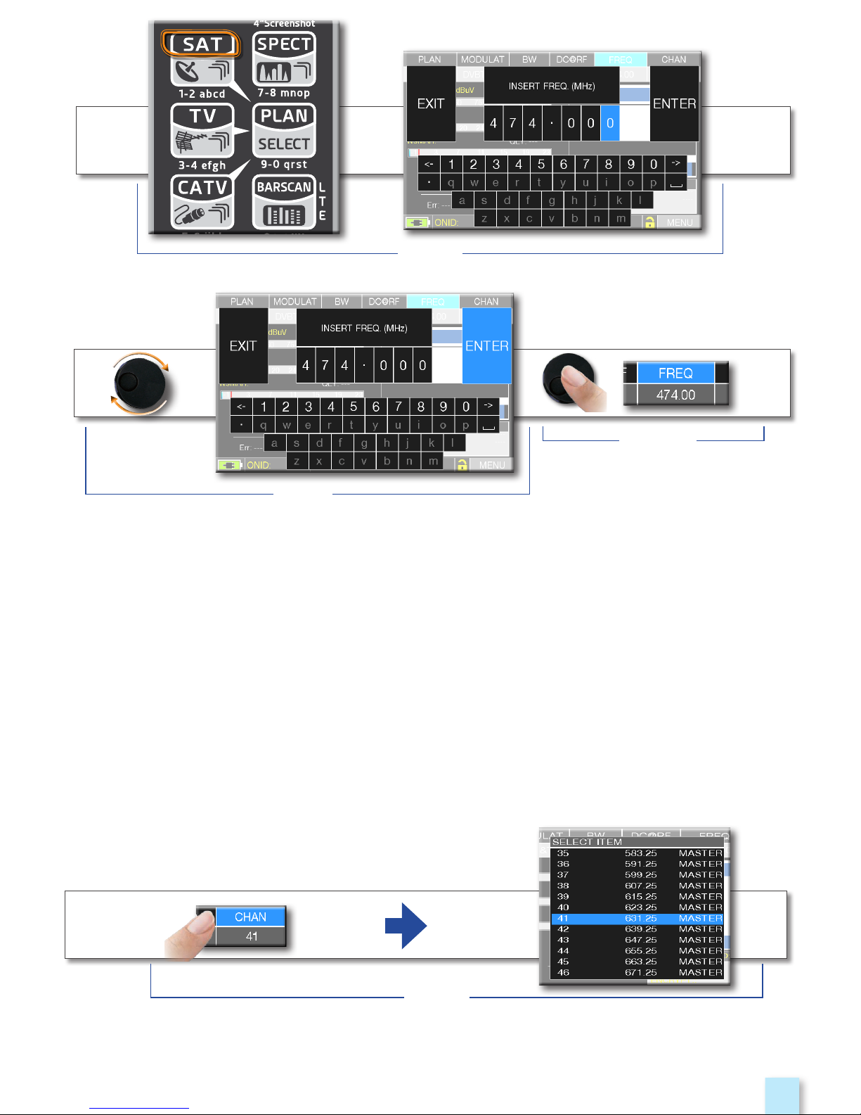
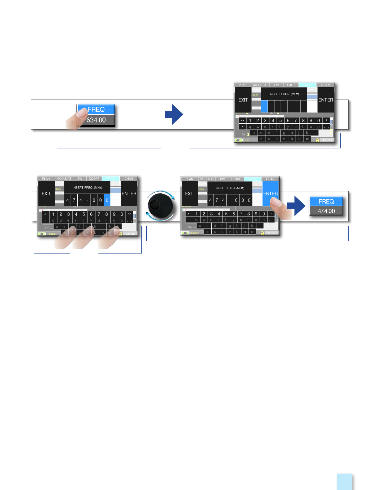
How to select the frequency and set the value using the numerical keyboard:
• Rotate the wheel and select frequency (FREQ) (fig. 1)
• Keep the wheel pressed for 2” to visualize the keyboard (fig. 2)
• Press the relative number keys to digit the frequency value required, rotate the wheel to
navigate within the window (fig. 3)
• Finally rotate the wheel and select enter (fig. 4)
• Press the wheel and confirm the selection (fig. 5)
Example of TV/CATV channel selection:
Example of SATELLITE transponder selection (TP/TS):
Example of manual frequency (FREQ) selection:
fig. 1
fig. 3
fig. 2
fig. 4
fig. 1
fig. 3fig. 2
fig. 4
fig. 1
fig. 2
Page 7
7
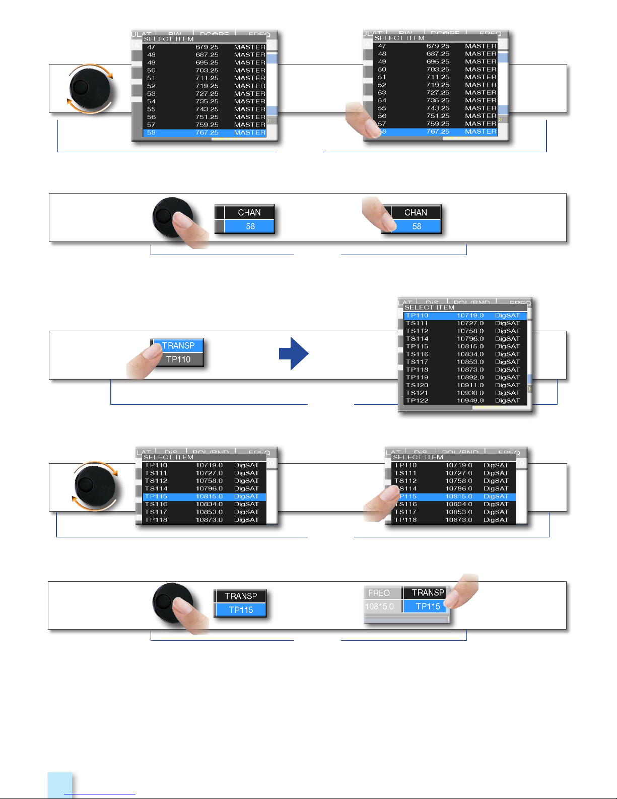
• Touch a value in the menu (fig. 1)
• Rotate the wheel to adjust the value (fig. 3) or touch the value required (fig.2)
• Press the wheel and confirm the selection (fig.3)
or touch the monitor outside the drop down menu (fig.3)
NAVIGATION USING MIXED COMMANDS: MECHANICAL & TOUCH
fig. 5
fig. 4
fig. 3
Select from the menus and adjust the value using the drop down menu:
• Touch a value in the menu to visualize the drop down menu (fig. 1)
• Rotate the wheel to adjust the value (fig. 2) or touch the value required (fig. 2)
• Press the wheel and confirm the selection (fig. 3), or touch the monitor outside the drop down
menu (fig. 3)
Example of TV channel selection:
fig. 1
Page 8
8
O
R
O
R
Example of SATELLITE transponder selection (TP/TS):
O
R
O
R
fig. 2
fig. 3
fig. 1
fig. 2
fig. 3
Page 9
9
Select the frequency and set the value using the numerical keyboard:
• Touch FREQ to show the menu “INSERT FREQ” (fig. 1)
• Touch the numbers to digit the required frequency value (fig. 2)
• Finally touch enter and confirm the selection (fig. 3)
Example of manual frequency selection (FREQ):
fig. 1
fig. 2
fig. 3
Page 10

10
CONFIGURATION
BATTERY SAVING AND TIMER OFF
________________________
VIDEO IN AND HDMI OUT
__________________________________
Volume selection is
immediately active, press
“ENTER” for the Display
configuration and other
important settings
Choose “BATTERY SAVING”
from the volume screen. In ON mode,
if no key is pressed, after 30 seconds,
the display brightness is reduced and
after 5 minutes the meter automatically
turns off. press any key to temporarily
reset the battery save mode.
Touch “CONFIGURATION MENU” then
“METER” in the volume screen and set
the “TIMER OFF” value required. The meter
will turn off after 5, 10, 15 or 30 minutes of
inactivity. Press any key to interrupt the
automatic turn-off.
Settings for battery save mode.
• “HDMI OUT” (connector 2): Connect an HDMI cable to automatically send the TFT monitor
pictures to a TV or video projector. The video will only be available on an external display;
• “VIDEO IN” (connector 7): Select “EXT” to visualize an external video source.
Page 11
11
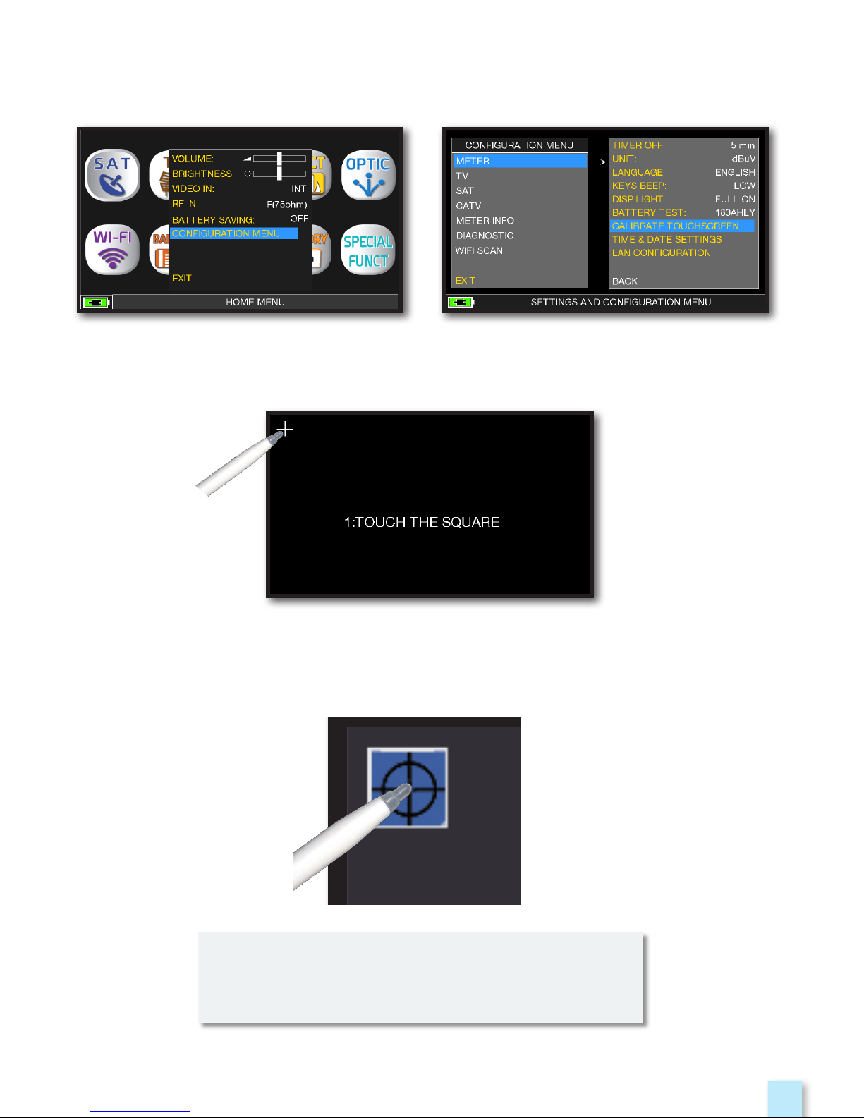
Touch the center of the squares that appear
in the corners of the screen,
repeat four times for every squares.
NOTE: use the pen and touch the the screen
exactly in the center of the circle. if you do not
carry out this procedure correctly the touch
commands may be inaccurate.
TOUCHSCREEN CALIBRATION
_____________________________
Touch “CONFIGURATION MENU”
from the volume window;
Touch “METER”
then “CALIBRATE TOUCHSCREEN”;
if the touchscreen does not respond to the commands, it may be necessary to calibrate:
Page 12
12
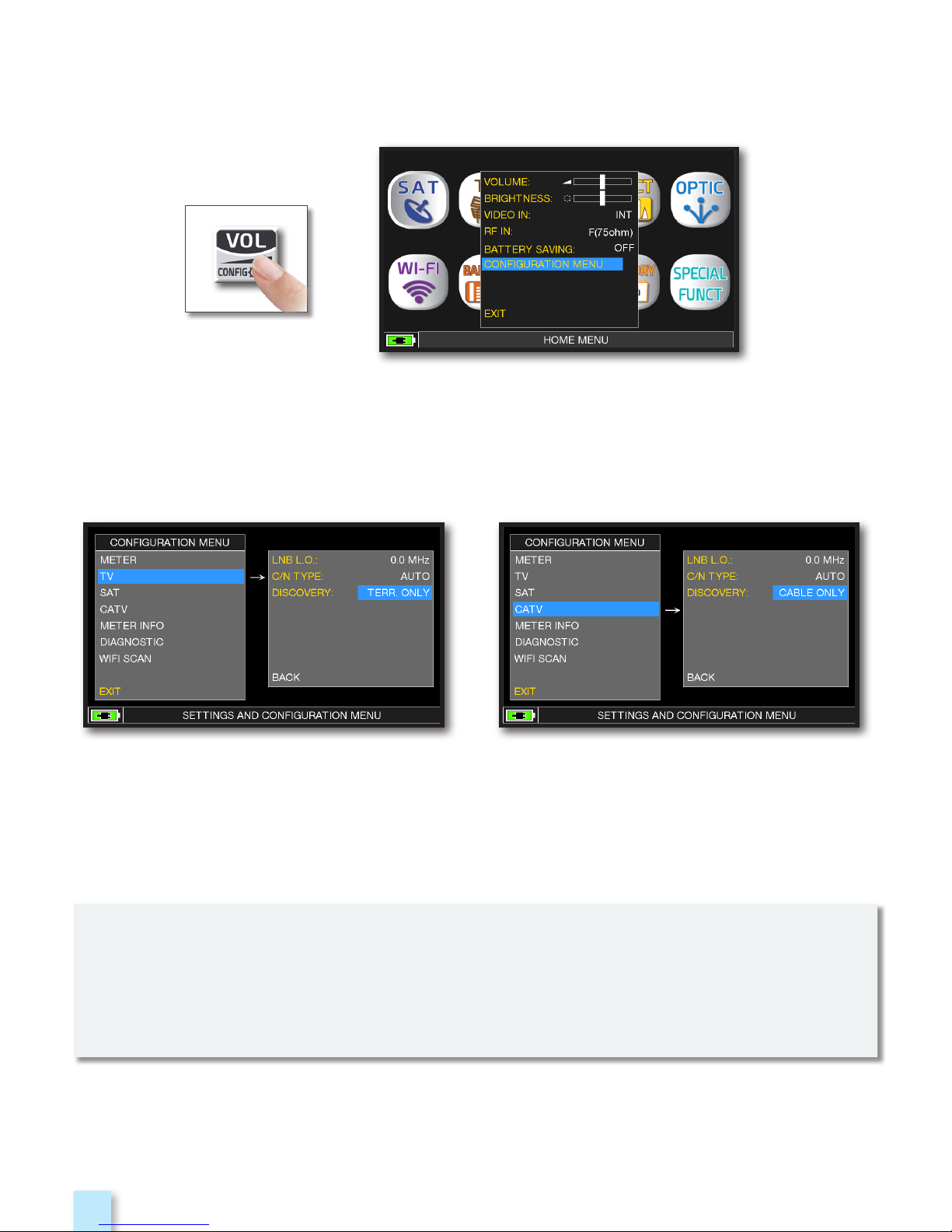
DISCOVERY
_____________________________________________________
Touch the “CONFIGURATION MENU”
in the VOLUME window.
TV MODE
____________________
CATV (CABLE) MODE
____
Identifies the modulation of a tuned TV channel in the TV master PLAN
Touch “TV” and then “DISCOVERY”
and set the identification mode:
- TERR ONLY
- TERR & CABLE
Touch “CATV” and then “DISCOVERY”
and set the identification mode:
- CABLE ONLY
- TERR & CABLE
NOTES:
- DISCOVERY mode is active only if the antenna cable is connected to the instrument
- DISCOVERY mode is not active if you use a manual (ManuMemory Mix) or automatic
memory plan (Automemory TV)
Page 13
13
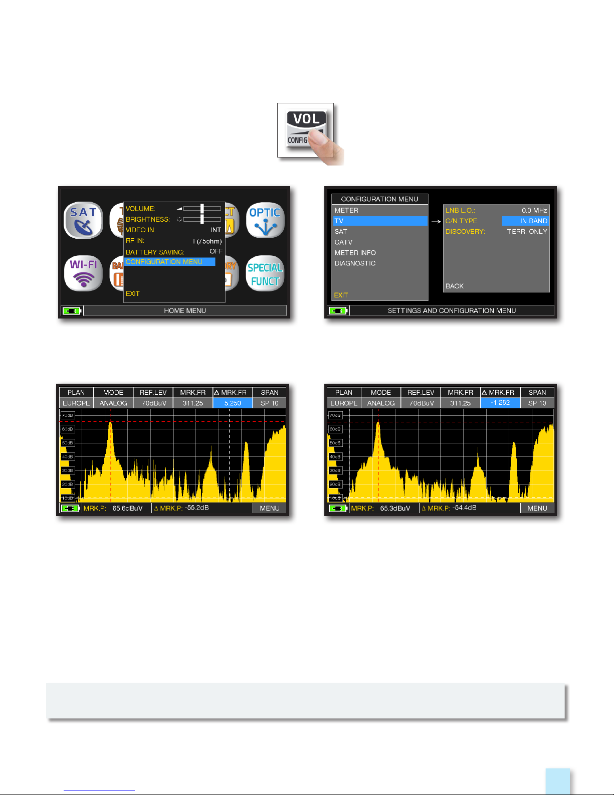
C/N TYPE
_____________________________________________________________
Set the measurement mode of the carrier noise ratio “C/N” (in band-out band).
C/N measurement mode “OUTSIDE THE BAND”:
The signal/noise ratio is measured between the
signal level of the video carrier
(signal/carrier, red marker) and the noise level
estimated in the guard band
(-1.282 MHz from the video carrier, white marker).
Touch ‘CONFIGURATION MENU’
from the volume screen.
Touch “TV” then “C/N TYPE”.
C/N measurement mode “IN BAND”:
the signal/noise ratio is measured
between the signal level of the video
carrier (signal/carrier, red marker) and the
noise level, estimated in the band between
the coloured subcarrier
and the audio carrier (white marker).
NOTE: the “C/N TYPE” setup is available in TV and CATV mode.
Page 14
14
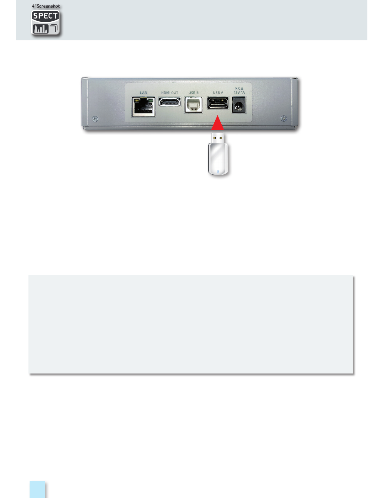
SCREEN SHOT
The “SCREEN SHOT” function allows you to directly save the TFT monitor screens in an external
memory.
• Connect an external memory source (not provided) to the USB A socket.
• Set the instrument on the screen to be saved: Spectrum, Measurements, Constellation,
Echoes etc.
• Press the SPECT (4” Screenshot) key for 4 seconds keys and wait for file to be saved:
the instrument will make a series of beeps.
• Digit the file name and touch ENTER.
N.B.:
• If the memory is not inserted correctly, or is not recognised, the following message will be
shown: “PLEASE INSERT USB MASS STORAGE DEVICE”.
• Full screen picture zooms can not be saved.
• the ENTER command is not active If the file name is already present in the external
memory source.
• The files are saved in .bmp (bitmap) format.
Page 15
15
SATSAT
SATSAT
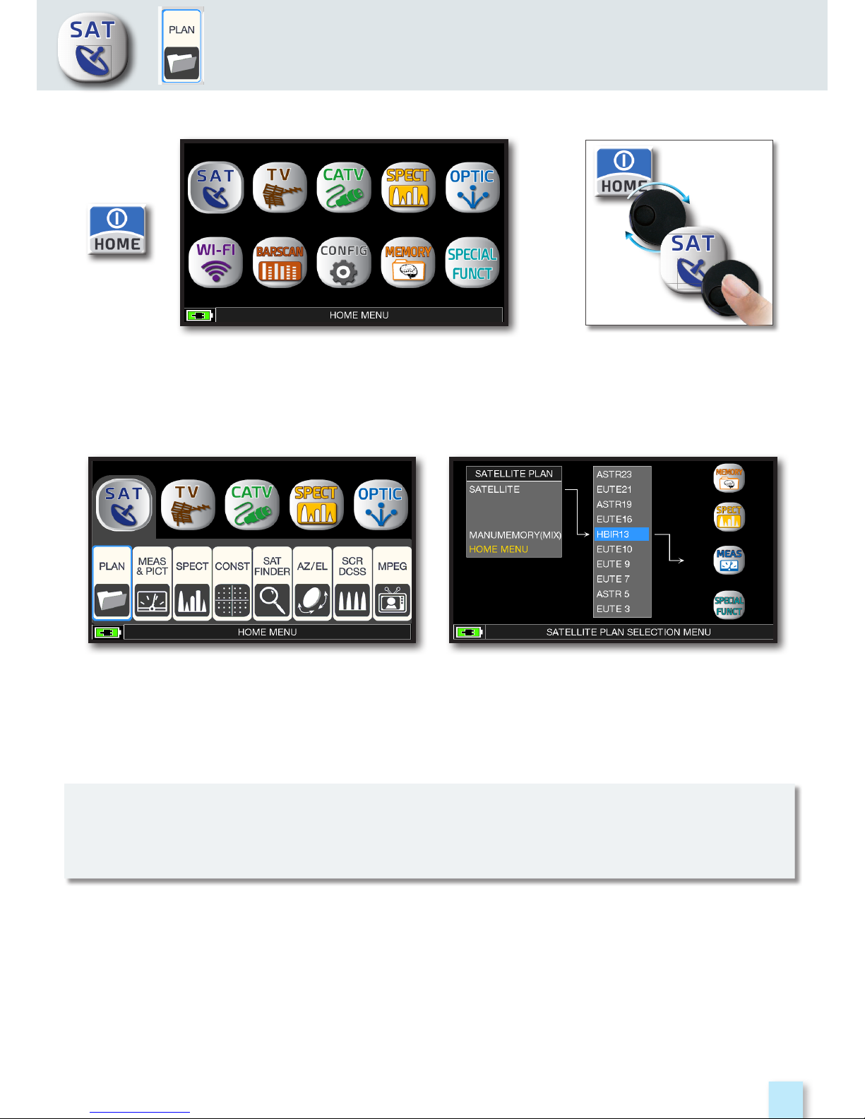
SAT MEASUREMENTS
Press the “HOME” key.
Touch “SAT”, and then “PLAN”
or use the encoder to obtain the
Satellite list.
Touch directly the desided satellite, or use
the encoder. At the end touch “MEAS” to
make the measure or “SPECT” for visualize
the spectrum.
NOTE:
The chosen Satellite and Transponder will remain in memory also if you change mode
(TV/CATV) or if you switch off the meter.
o
r
Page 16
16
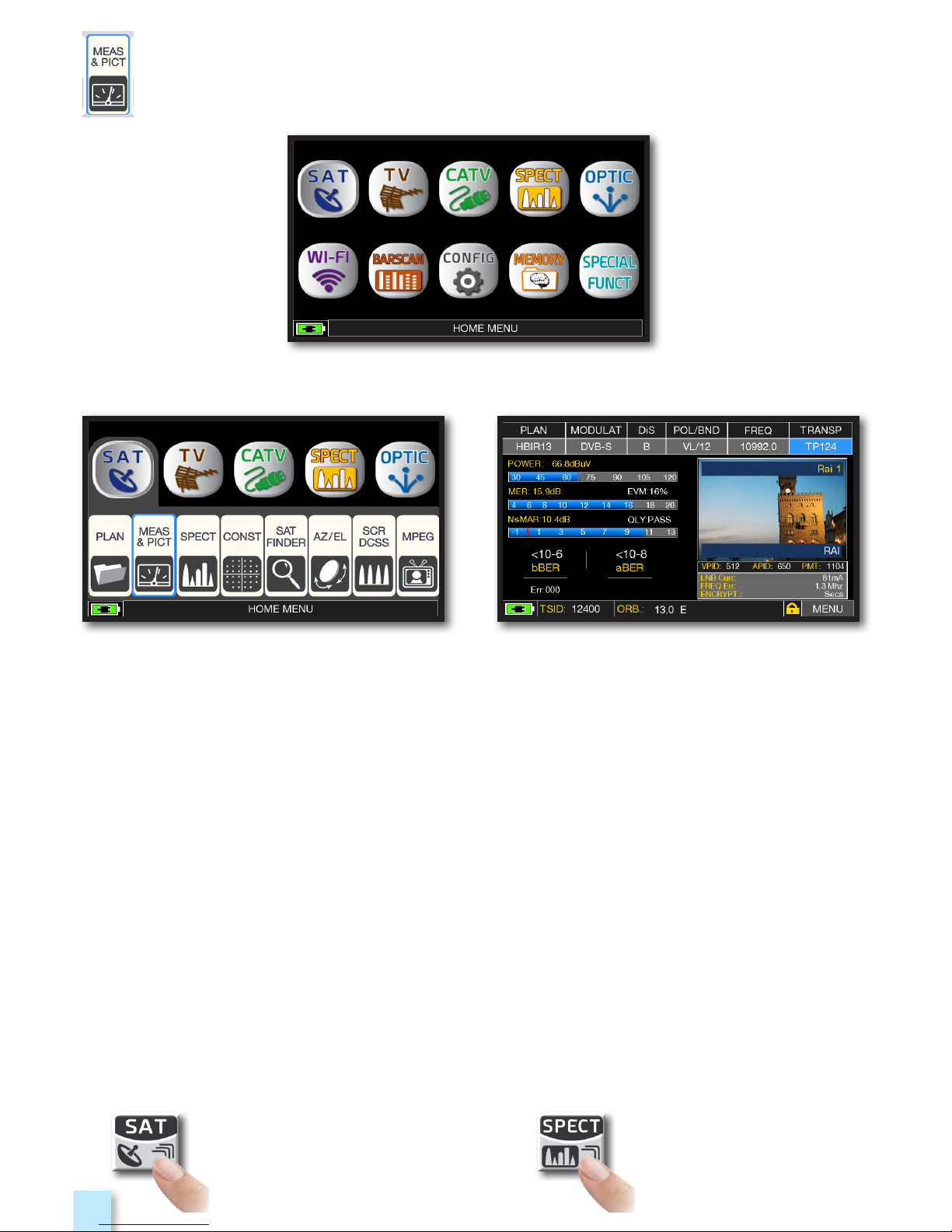
RELATED FUNCTIONS
_________________________________________
DVB-S, DVB-S2 & S2M SAT MEASURES
_______________
Press the “HOME” key.
Main measures and image.Touch “SAT” and then “MEAS & PICT”
or use the encoder.
Press repeatedly to navigate into
SAT measures screens: Measures,
Constellation.
Press to enter in
the spectrum.
Page 17
17
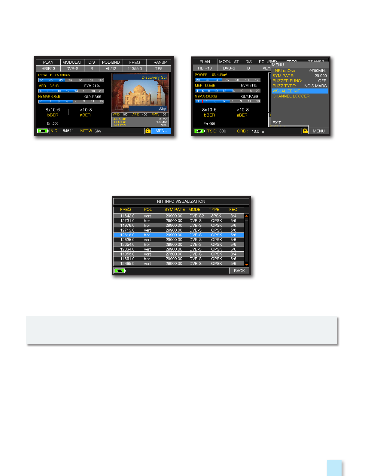
VISUALIZE NIT
___________________________________________________
“NIT INFO VISUALIZATION” referring
to an HOTBIRD 13° East transponder
Touch “VISUALIZE NIT”.Touch “MENU&?” from the “MAIN
MEASUREMENTS & PICTURES”.
Example 1:
NOTE:
The function VISUALIZE NIT is available also in TV & CATV mode
Page 18
18
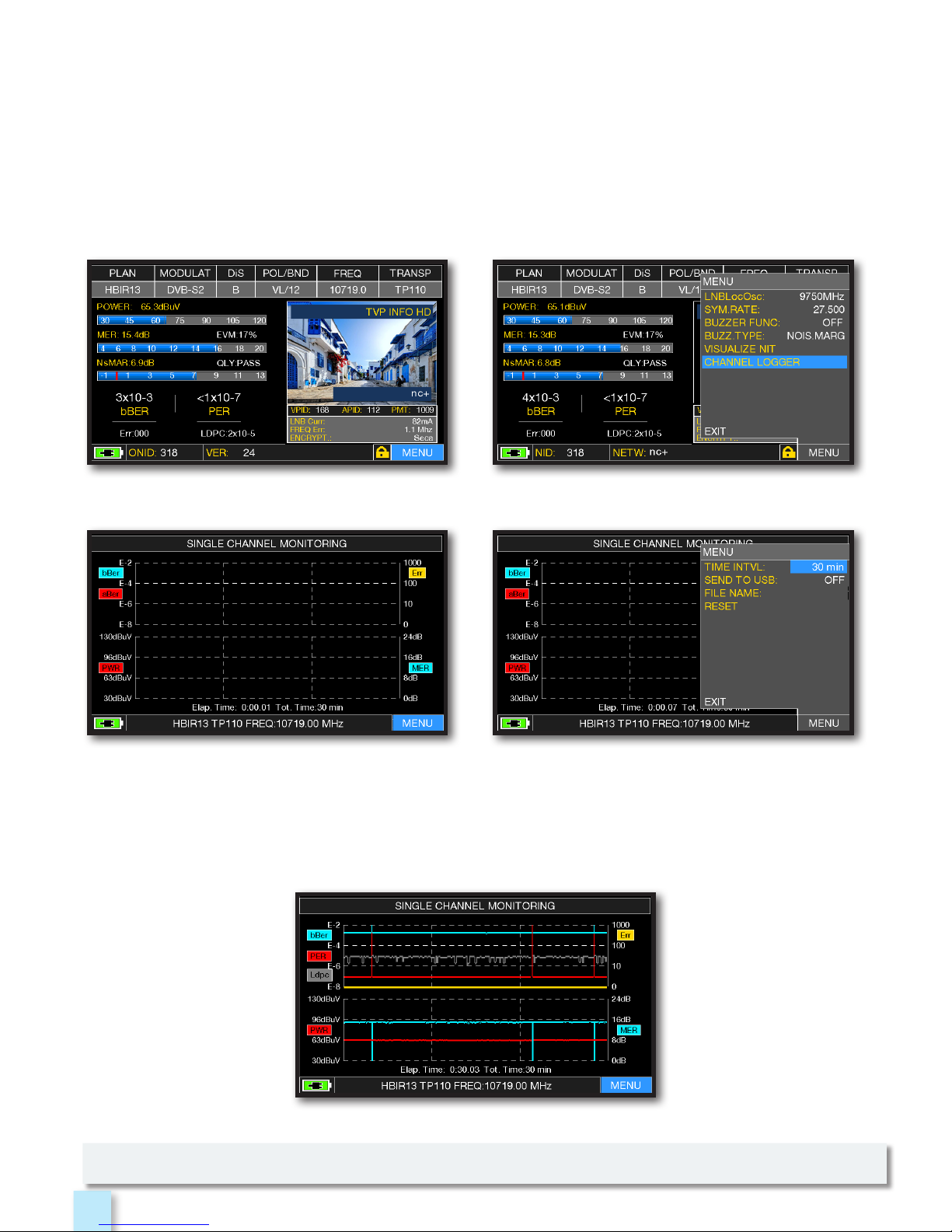
CHANNEL MONITOR
__________________________________________
NOTE: the Channel Monitor function is available also in TV and CATV mode.
Example 1:
SINGLE CHANNEL MONITORING: 30 minutes.
Touch “MENU” from MAIN MEASURES &
IMAGES screen.
Touch “CHANNEL LOGGER”.
Tou c h “ M E NU ”.
Select the time interval (TIME INTVL)
and where you want to store the file,
either in the meter’s memory, or in the USB
memory stick (send to USB-ON),
with the relative file name (File name).
The weekly application of SW CHANNEL MONITOR allow you to controll and register the trend
of the main parameters of a digital signal over time (from 30 minutes to one week): TV, CATV &
SAT. This application is indicated to resolv the reception problems which occur occasionally,
it allow you also to measure, memorize and visualize (local or in remote) the digital signals
parameters tested: DVB-S/T/C = Power, MER, ERROR, bBer, aBer; DVB-S2 / T2 / C2 = Power, MER,
ERROR, aBer, Lber, PER, LDCP.
Every registered parameters is graphically represented on the display using differents colours
for a easy identification.
Page 19
19
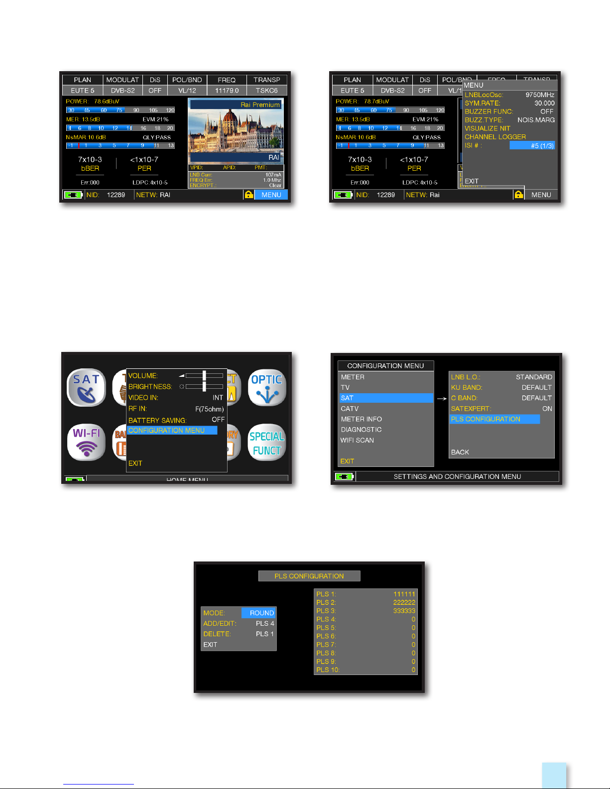
Example 1:
DVB-S2M SIGNAL: ISI SELECTION
_________________________
PLS CONFIGURATION
__________________________________________
Touch “MENU” on the main measurements
and picture screen
Touch “CONFIGURATION MENU” in the
volume window
Select the PLS required and set the
parameters
Touch “ISI #” and select the ISI
(Transport Stream) required
Touch “SAT” and select “PLS
CONFIGURATION”
Page 20
20
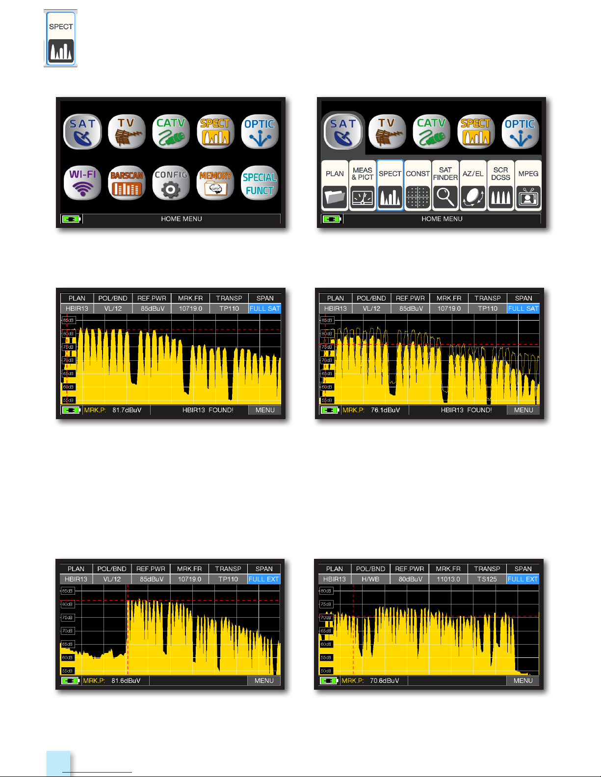
SAT SPAN FULL SAT Spectrum
(from 930 to 2250 MHz).
éress again the SPECT key to activate the
“MAX HOLD” function.
Press the “HOME” key.
Touch “SAT” and then “SPECT”or use the
encoder.
“SAT” spectrum SPAN FULL EXT
(from 230 to 2610 MHz) with universal LNB.
“SAT” spectrum SPAN FULL EXT
(from 230 to 2610 MHz) with LNB WIDE BAND.
Example 2:Example 1:
Touch “SPAN” and rotate the encoder to select the SPAN value desired:
10-20-50-100-200-500-FULL SAT-FULL EXT
SPECTRUM ANALYZER
____________________________________
Page 21
21
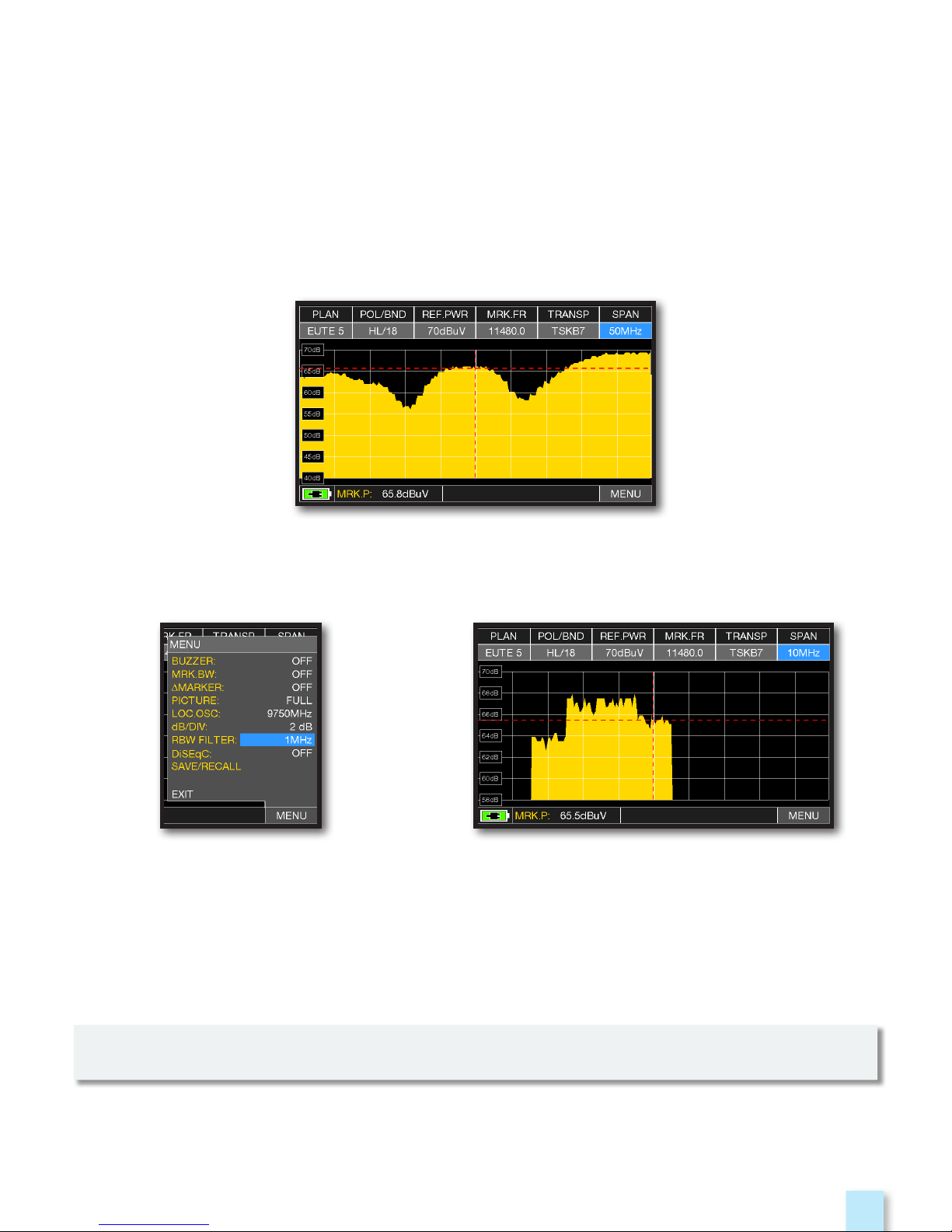
RBW FILTER
______________________________________________________
Visualization of an SCPC transponder with settings:
“RBW FILTER 5 MHz” and “dB DIV 5dB” (Span 50 MHz)
Touch “MENU&?” from the
SAT SPECTRUM screen,
select “dB DIV 2dB” and
“RBW FILTER 1 MHz”.
Visualization of a SAT SCPC transponder
(SPAN 10 MHz).
EXAMPLE 1:
EXAMPLE 2:
NOTE: You can only select RBW filter in SAT mode.
The RBW (Resolution Bandwidth) filter function determines the bandwidth of the bandpass filter,
which is used to generate the spectrum of the input signal (IF).
This bandpass filter works like a window: the smaller the bandwidth, the more detailed is the
representation of the spectrum. However, a smaller value RBW provides a slower refresh rate of
the spectrum.
You can choose (high resolution, slower refresh rate) between the RBW filter between a
bandwidth of 1 MHz or 5 MHz (lower resolution, fast refresh rate).
Page 22
22
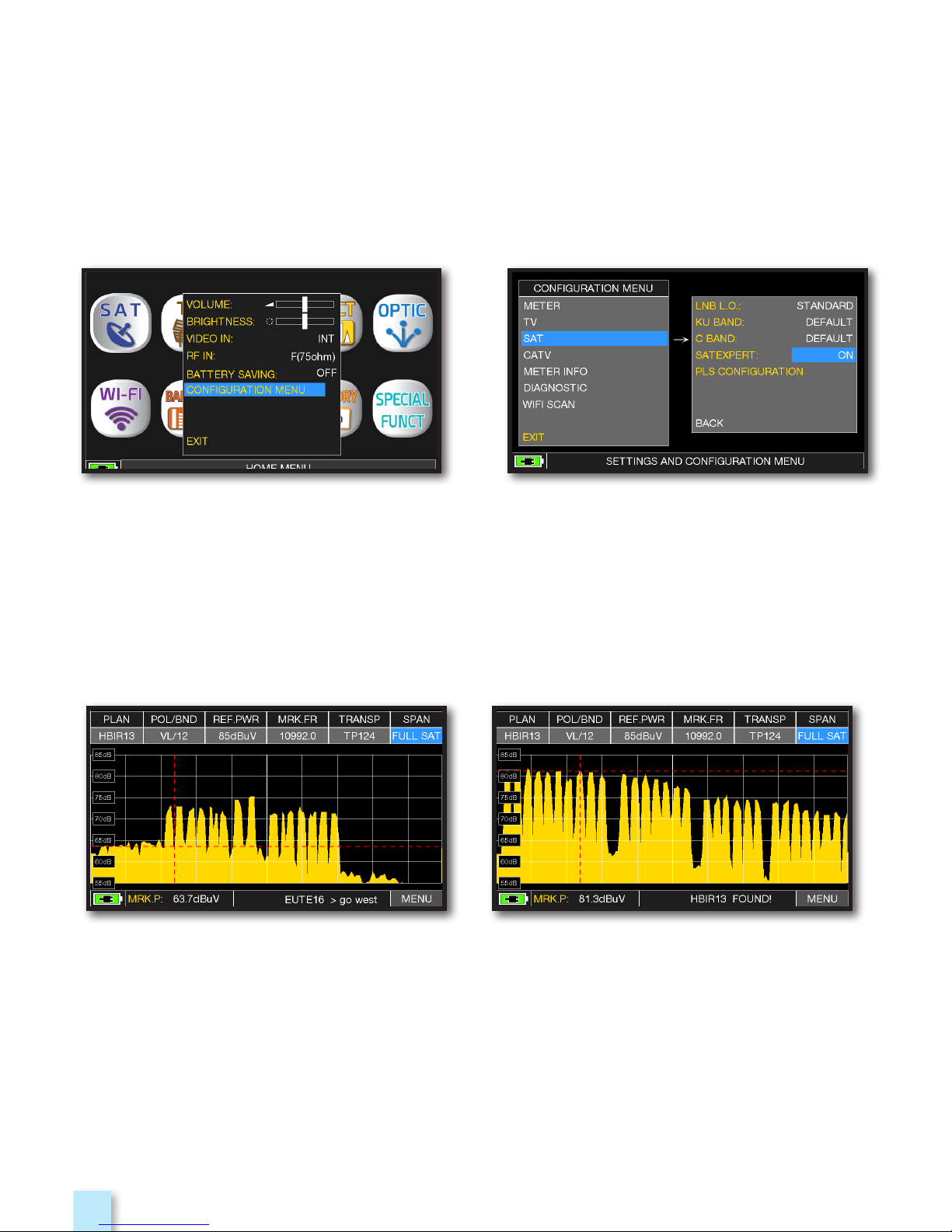
SAT EXPERT
___________________________________________________________
The SATEXPERT SW function (guided satellite tracking function), is a valuable aid for a fast
satellite antenna pointing to a wanted satellite.
Through text messages, which appear from time to time on the screen, the measuring
instrument will indicate in which direction to move the satellite dish, to the east or to the west,
until you reach the wanted satellite.
EXAMPLE 1: EXAMPLE 2:
The satellite you have pointed is not correct.
the lower part of the display shows the
following information:
EUTE 16 > G0 WEST
(move the satellite dish west).
Satellite found.
the lower part of the display shows the
following information:
HBIR13 FOUND!
(the satellite that has been pointed is correct)
Touch “CONFIGURATION MENU”
from the VOLUME screen
In SAT mode, press the PLAN key and select the satellite to be pointed, for example HBIR
13.
Press the SPECT key, touch “SPAN” and select “Satxprt”.
Here you can find some examples:
Touch “SAT”, then in “SAT EXPERT”
and select “ON”
Page 23
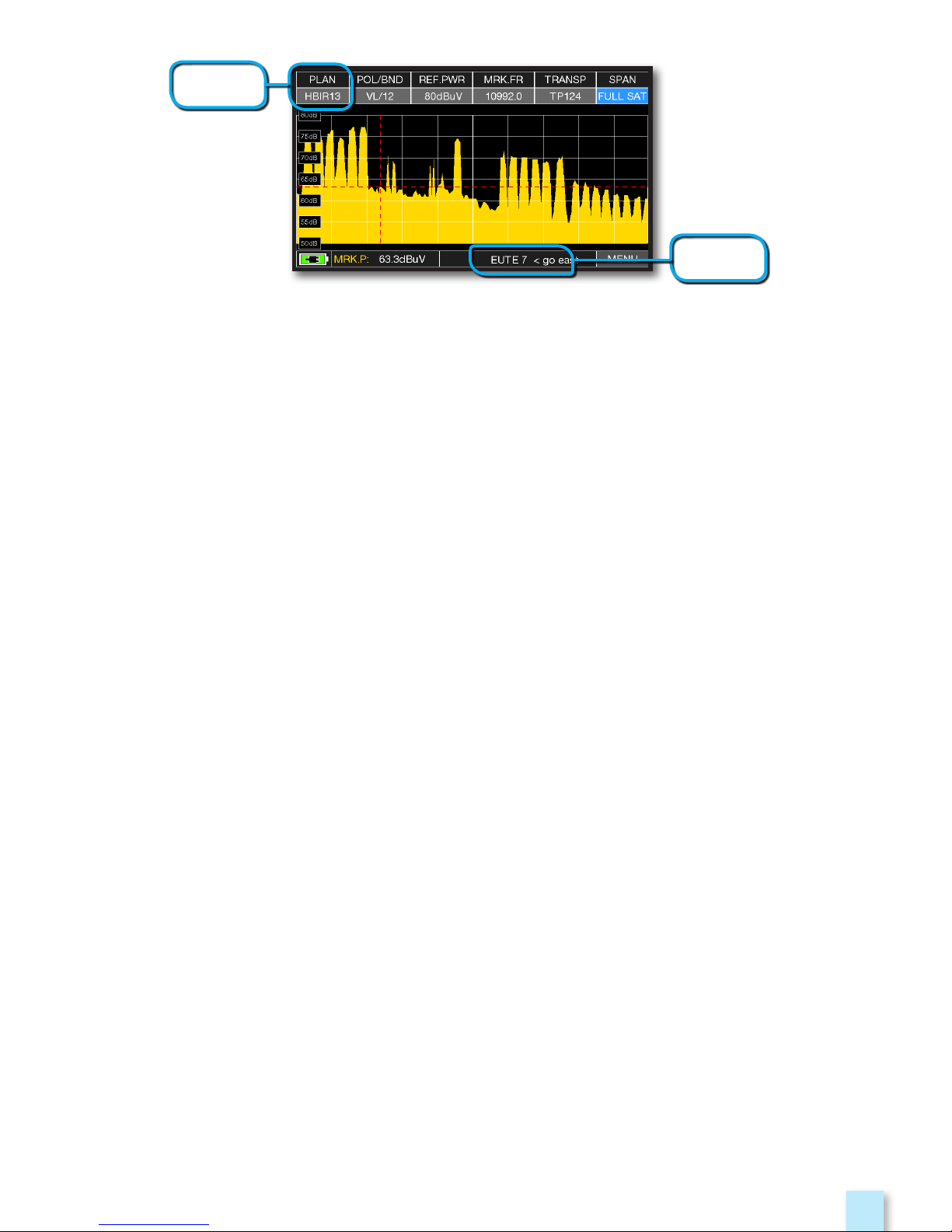
23
The pointed Salellite is not the correct one.
The lower part of the display shows the following information:
EUTE7 < G0 EAST (move the satellite dish EAST).
EXAMPLE 3:
SAT to
be found
SAT
detected
IMPORTANT: The text messages that from time to time will appear on the screen of the
instrument when moving the satellite dish to east or west, are bounded to the diameter of the
used antenna: 60-80-90 cm etc.
Therefore, using antennas with a small diameter, the messages related to some satellites may
not be reported.
Page 24
24
RELATED FUNCTIONS
_________________________________________
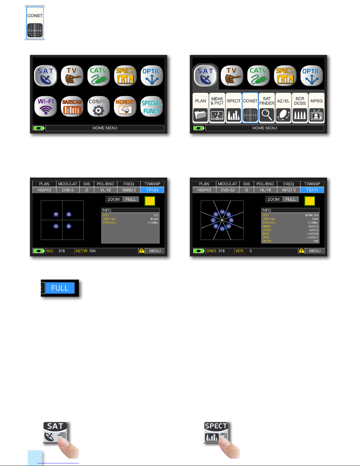
CONSTELLATION ANALYSIS
_______________________________
Press the “HOME” key. Touch “SAT” and then “CONST”
or use the encoder.
Touch “FULL and select the zone of constellation to elnarge.
QPSK constellation. 8PSK constellation.
Example 2:Example 1:
Press repeatedly to navigate into
SAT measures screens: Measures,
Constellation.
Press to enter in
the spectrum.
Page 25
25
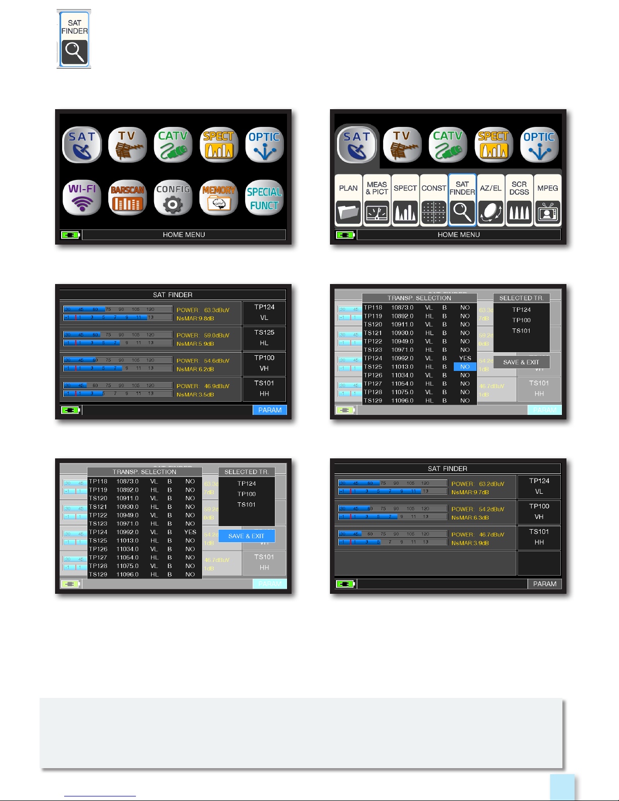
SAT FINDER
________________________________________________
Press the “HOME” key. Touch “SAT” and then “SAT FINDER”
or use the encoder.
Satellite locked.
Touch the selected transponder, touch
YES/NO to added or delete from list.
Touch “SAVE & EXIT” to save and exit.
Touch “PARAM” to modify the
transponders list.
Satellite locked.
The SAT FINDER function allow you to check the quality of 4 transponders simultaneity
and to check the operation of the 4 LNB polarities.
If the chosen satellite is found the buzzer will start, if this does not happen, continue looking
for the right satellite. Optimize the dish alignment and skew to obtain the maximum NsMAR
value (noise margin).
NOTE: For a proper use of the “SAT FINDER” function, verify the tuning parameters for all three
transponders (frequency, polarity, band, and symbol rate) and the type of lnb you are using
(universal or quatro)
Go to the www.lyngsat.com site for more information
Page 26
26
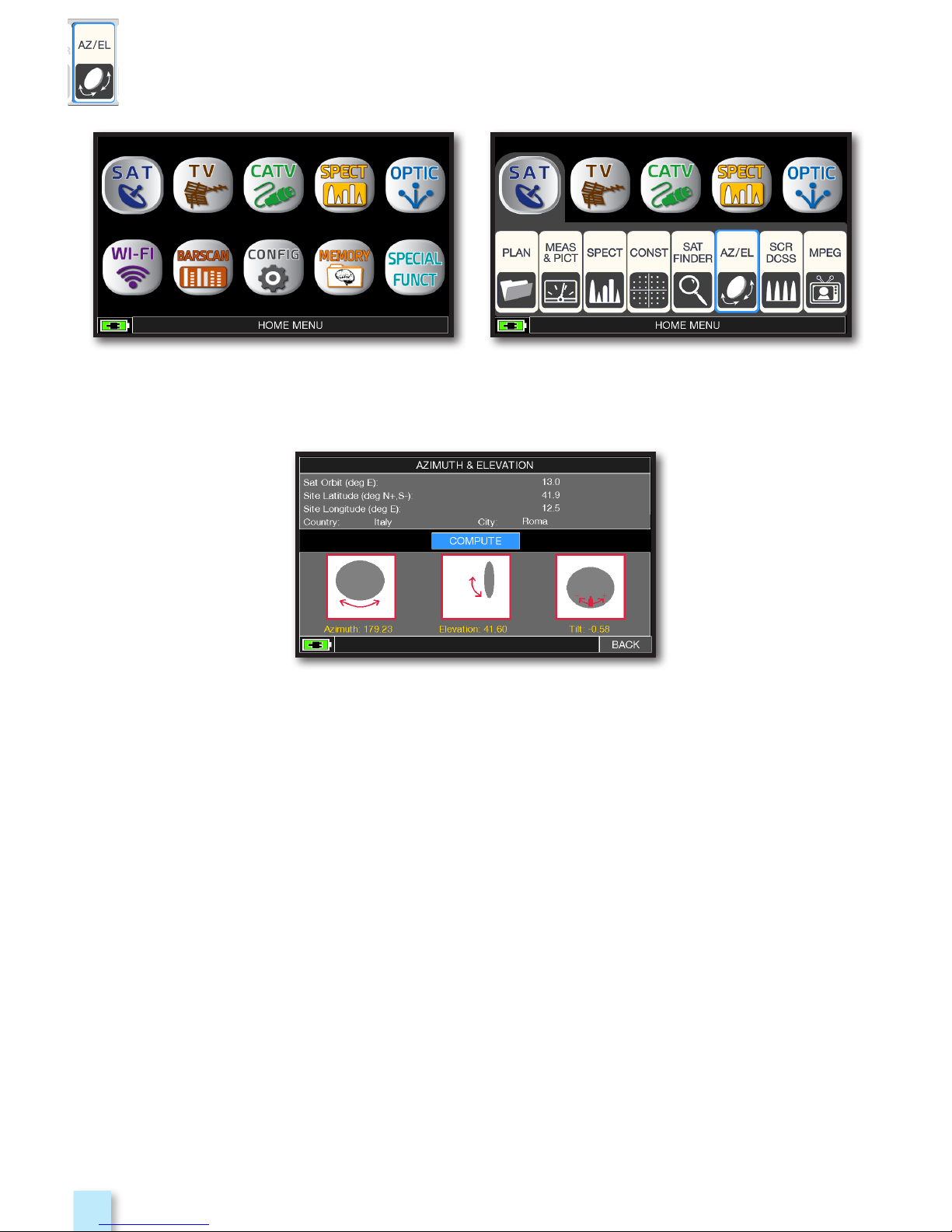
Calculation of the pointing data:
- Touch “SAT ORBIT” and set up the orbit position of the desired
satellite, for example 13,0 EAST.
- Touch “COUNTRY” and select your Nation, for example Italy.
- Touch “CITY” and select your city, for example Roma.
- Touch “COMPUTE” to obtain the automatic calculation of
pointing parameters: Azimuth, Elevation & Tilt.
Press “HOME” key. Touch “SAT” and then “AZ/EL”.
AZ/EL POINTING DATA
_____________________________________
Page 27

27
Touch the “HOME” key. Touch “SAT” and then “SCR DCSS”
or use the encoder.
SCR test.
SCR measures.
Or touch “TEST”, in Spectrum mode,
to perform a verify of the 8 exit frequencies
(user 1-4) from LNB/multiswitch.
MEASURES WITH SCR LNB/MULTISWITCH
__________
- Touch “LNB TYPE” and select the installed
LNB/multiswitch model (see NOTE).
- Touch “USER” and select the user’s number
to test (user 1-4).
- Press “SPECT” to visualize the spectrum
or “SAT” to make the measure.
Page 28

28
Press the “HOME” key. Touch “SAT” and then “SCR DCSS”
or use the encoder.
dCSS test.
dCSS measures.
Or touch “TEST”, in Spectrum mode,
to perform a verify of the 8 exit frequencies
(user 5-16) from LNB/multiswitch.
LNB/MULTISWITCH dCSS MEASURES
________________
- Touch “LNB TYPE” and select the installed
LNB/multiswitch model (see NOTE).
- Touch “USER” and select the user’s
number to test (user 5-16).
- Press “SPECT” to visualize the spectrum
or “SAT” to make the measure.
Page 29

29
IMAGES VISUALIZATION & SERVICE CHOICE
__________
Images and MPEG service list.
Touch the image to enlarge.
Touch again to come back at the service list.
RADIO & TV service selection.
Press “HOME” key. Touch “SAT” and then“MPEG”
ou use the encoder.
Touch directly the RADIO/TV desired
service or use the encoder.
or touch “Vpid-Apid” in Measure screen.
Page 30

30
Press the “HOME” key.
Touch “TV” and then “PLAN”
or use the encoder to access
at the TV canalizations list.
Touch directly the desided canalization
or use the encoder. At the end touch
“MEAS” to make the measure or “SPECT”
for visualize the spectrum.
TVTV
TV MEASURE
TVTV
o
r
NOTE:
The chosen canalization and channel will remain in memory also if you change mode
(CATV/SAT) or if you switch off the meter.
Page 31

31
RELATED FUNCTIONS
_________________________________________
Press the “HOME” key.
Main menu and image.Touch “TV” and then “MEAS & PICT”
or use the encoder.
Press to enter in
the spectrum.
DIGITAL TV MEASUREMENT DISPLAYS DVB-T & DVB-T2 M-PLP
Press repeatedly to navigate
into TV measures screens:
Measures, Constellation.
Page 32

32
DVB-T2 SIGNAL: PLP SELECTION
________________________________
DVB-T2 SIGNAL: PROFILE SELECTION
_________________________
Touch “MENU” from
MAIN MEASURES & IMAGES screen.
Touch “MENU” from
MAIN MEASURES & IMAGES screen.
Touch “PLP #” and select the desired PLP
(transport Stream)
Touch “PROFILE”
and select the desired profile:
“Basic” or “Lite”.
Page 33

33
TV spectrum SPAN 50 MHz Press again te spectrum key to activate the
“MAX HOLD” function.
Press the “HOME” key.
Touch “TV” and then “SPECT”
or use the encoder.
“TV” SPAN FULL spectrum
(from 5 to 1.250 MHz).
TV SPAN FULL spectrum with mixed
channels SAT signals (from 5 to 1.250 MHz).
Example 2: Example 1:
Touch “SPAN” and rotate the encoder to select the desired SPAN value:
1-2-5-7-10-20-50-100-200-500-FULL-UHF VHF
SPECTRUM ANALYZER
____________________________________
Page 34

34
CONSTELLATION ANALYSIS
_______________________________
Press the “HOME” key. Touch “TV” and the “CONST”
or use the encoder.
Touch “FULL” and select the box of constellation to enlarge.
Constellation DVB-T. Constellation DVB-T2.
Example 2: Example 1:
RELATED FUNCTIONS
_________________________________________
Press to enter in
the spectrum.
Press repeatedly to navigate
into TV measures screens:
Measures, Constellation, echoes,
MER vs CARRIER
Page 35

35
MER VS CARRIER MEASUREMENT
_______________________
The MER vs CARRIER measure allow to make analysis of the trend MER for single COFDM carriers
which make up a signal DVB-T or DVB-T2.
Press the “HOME” key. Touch “TV” and then “MER vs CARRIER”
or use the encoder.
Touch “MENU & ?” to obtain
different visualization modes.
MER vs CARRIER: visualization mode
“VIS. TYPE: NORMAL” & “PICTURE: FULL”
Page 36

36
MER vs CARRIER : visualization mode
“VIS. TYPE: NORMAL” & “PICTURE: CONTOURS”.
Example 3:
Example 1: Example 2:
MER vs CARRIER : visualization mode
“VIS. TYPE: REVERSE” & “PICTURE: FULL”
MER vs CARRIER: visualization mode
“VIS. TYPE: NORMAL”, “PICTURE: FULL” & “START/STOP CARR
from 3000 to 4000”.
RELATED FUNCTIONS
_________________________________________
Press repeatedly to navigate
into TV measures screens:
Measures, Constellation. echoes,
MER vs CARRIER.
Press to enter in
the spectrum.
Page 37

37
Touch “MENU”, than “TYPE”
and select “µECHOES”.
NOTE: Other echo visualization modes are available in the “TYPE” menus
MicroEchoes visualization,
touch the Marker and rotate the
encoder to select the ECHOES.
MICROECHOES VISUALIZATION
________________________________
Touch “TYPE”
and select the echoes
visualization mode:
DISTANCE or TIME
Impulse response (echo).
ECHOES ANALYSIS
__________________________________________
Press the “HOME” key. Touch “TV” and then “ECHOES”
or use the encoder.
Page 38

38
The analogue TV switch off is fi nish in Europe. Some countries, such as Spain and Italy, have decided to install digital TV “SFN”
(Single Frequency Networks), in other words a national television broadcaster has the same frequency/channel all over the
country. This provides a fantastic opportunity, but also means that in areas between two cells, it is possible to receive the same
signals from more than one transmitter.
If the “SFN” network has been designed well, the SFN signals’ slight propagation delay (which we will call “echoes”), coming from
the different distances in which the transmitters are situated, becomes absorbed in the invaluable GUARD INTERVAL function,
present in the DVB-T & T2 (COFDM) modulation and consequently there will not be any reception problems. In any case,
experience over the last few years has shown us that reality is different to theory, especially when there are many local television
networks that could generate many interferences.
You could therefore encounter the unpleasant experience of receiving a signal with good power, but that cannot show any
pictures and not be able to establish the cause of the fault. In this case it is indispensible to measure the IMPULSE RESPONSE
in real time, to measure the echo’s delay or advance compared to the main signal. When changing direction and position of the
antenna it is possible to optimize reception intuitively, by maximising the power of the main signal and minimize the power of
interference echoes, also at the expense of the channel power.
Once again Rover Instruments is the fi rst company to supply meters for TV installers, that can measure up to 16 ECHOES and
PRE-ECHOES in real time. ROVER meters allow you to see ECHOES, measure the power and the delay in uS and the distance
of the interfering broadcaster in Km. There are currently very few meters that allow you to measure ECHOES and PRE-ECHOES,
in real time and at a distance of up to 75 Km, higher than the maximum amplitude possible with the GUARD INTERVAL and above
all that can highlight, using the green mask, the useful reception area, in other words within the guard interval.
The width of the GUARD INTERVAL varies according to the modulation parameters: consult the table below to fi nd the width of
the GUARD INTERVAL and all the possible DVB-T confi gurations.
Fig. 4:
DVB-T-64Q CONSTELLATION:
The table to the right shows all the
received modulation parameters
N.B.* Valid examples for a DVB-T
OFDM 8k signal with an 8 MHz
Bandwidth and a 1/8 Guard Interval,
this data is shown on ROVER meters
to the right of the Constellation, see
below Fig. 4
.
ECHO & MICROECHO MEASUREMENT in “SFN” TV NETWORKS
HOW TO REDUCE INTERFERENCES IN “SFN” NETWORKS
DVB-T 2.000 carriers (2K DVB-T)
GUARD INTERVAL
1/4
1/8 1/16 1/32
max time (microsecondi) 56 28 14 7
max distance (Km) 16.8 8.4 4.2 2.1
DVB-T 8.000 carriers (8K DVB-T)
GUARD INTERVAL
1/4
1/8 1/16 1/32
max time (microsecondi) 224 112 56 28
max distance (Km) 67.2 33.6 16.8 8.4
TEMPORAL GUARD INTERVAL WIDTH
(already automatically highlighted by the GREEN mask)
Fig. 1:
OPTIMUM RECEPTION:*
no ECHO present either outside or inside
the guard interval mask (green area)
Fig. 2:
GOOD RECEPTION:* 2 ECHOES present,
but within the guard interval mask (green
area) coming from a distance of:
1st echo: 15 Km, the same as a 50 µs delay
2nd echo: 25 Km, the same as a 83 µs delay
Fig. 3:
MARGINAL RECEPTION (or IMPOSSIBLE):*
2 ECHOES present outside the guard interval
mask (green area), coming from a distance of:
1st echo: 40 Km, the same as a 133 µs delay
2nd echo: 45 Km, the same as a 150 µs delay
Page 39

39
Touch “TV” and then“MPEG”
ou use the encoder.
RELATED FUNCTIONS
_________________________________________
IMAGES VISUALIZATION & SERVICE CHOICE
__________
Images and MPEG service list.
Touch the image to enlarge.
Touch again to come back at the service list.
RADIO & TV service selection.
Press “HOME” key.
Press repeatedly to navigate
into TV measures screens:
Measures, Constellation. echoes,
MER vs CARRIER.
Press to enter in
the spectrum.
Touch directly the RADIO/TV desired
service or use the encoder.
or touch “Vpid-Apid” in Measure screen.
Page 40

40
CHANNEL MONITOR
_______________________________________
SINGLE CHANNEL MONITORING: 30 minutes.
Touch “MENU” Select the time interval (TIME INTVL) and where you
want to store the file, either in the meter’s memory,
or in the USB memory stick (send to USB-ON),
with the relative file name (File name).
NOTE: the Channel Monitor function is available also in CATV and SAT mode.
Example 1:
Press the “HOME” key. Touch “TV” and then “CH MONITOR”
or use the encoder.
The weekly application of SW CHANNEL MONITOR allow you to controll and register the trend
of the main parameters of a digital signal over time (from 30 minutes to one week): TV, CATV &
SAT. This application is indicated to resolv the reception problems which occur occasionally,
it allow you also to measure, memorize and visualize (local or in remote) the digital signals
parameters tested: DVB-S/T/C = Power, MER, ERROR, bBer, aBer; DVB-S2 / T2 / C2 = Power, MER,
ERROR, aBer, Lber, PER, LDCP.
Every registered parameters is graphically represented on the display using differents colours
for a easy identification.
Page 41

41
Press the “HOME” key.
Touch “CATV” and then “PLAN” or use
the encoder to access at the CATV
canalizations list.
Touch directly the desided canalization
or use the encoder. At the end touch
“MEAS” to make the measure or “SPECT”
for visualize the spectrum.
NOTE:
The chosen canalization and channel will remain in memory also if you change mode
(TV/SAT) or if you switch off the meter.
CATVCATV
CATV MEASURES
CATVCATV
o
r
Page 42

42
DIGITAL DVB-C & DVB-C2 MEASURES (opt.)
_____
Press the “HOME” key.
Main measures and image.Touch “CATV” and then “MEAS & PICT”
or use the encoder.
RELATED FUNCTIONS
_________________________________________
Press repeatedly to navigate
into CATV measures screens:
Measures, Constellation.
Press to enter in the
spectrum.
Page 43

43
CATV spectrum SPAN 50 MHz.
Press the “HOME” key.
Touch “CATV” and then “SPECT”
or use the encoder.
CATV spectrum SPAN “10 MHz”. CATV spectrum SPAN VHF.
Example 2: Example 1:
Press again te spectrum key to activate the
“MAX HOLD” function.
Touch “SPAN” and rotate the encoder to select the desired SPAN value:
1-2-5-7-10-20-50-100-200-500-FULL-UHF VHF
SPECTRUM ANALYZER
____________________________________
Page 44

44
Press the “HOME” key. Touch “CATV” and then “CONST”
or use the encoder.
64 QAM constellation. 256 QAM constellation.
Example 2: Example 1:
RELATED FUNCTIONS
_________________________________________
CONSTELLATION ANALYSIS
_______________________________
Touch “FULL” and select the box of constellation to enlarge.
Press to enter in
the spectrum.
Press repeatedly to navigate
into CATV measures screens:
Measures, Constellation.
Page 45

45
LEAKAGE
______________________________________________________
Press the “HOME” key. Touch “CATV” and then “LEAKAGE”
or use the encoder.
Set the desired parameters,
at the end touch “START” to start the
leakage measures.
Leakage measures.
Page 46

46
INGRESS
_____________________________________________________
Press the “HOME” key. Touch “CATV” and then “LEAKAGE”
or use the encoder.
Ingress measures.
Set the desired parameters,
at the end touch “START” to start
the Ingress measures.
Page 47

47
Press the “HOME” key.
Touch “CATV” and then “MPEG”
or use the encoder.
RELATED FUNCTIONS
_________________________________________
IMAGES VISUALIZATION & SERVICE CHOICE
__________
Images and MPEG service list.
Touch the image to enlarge.
Touch again to come back at the service list.
RADIO & TV service selection.
Press repeatedly to navigate
into CATV measures screens:
Measures, Constellation.
Press to enter in
the spectrum.
Touch directly the RADIO/TV desired
service or use the encoder
or touch “Vpid-Apid” in Measure screen.
Page 48

48
Touch “MENU”
NOTE: the Channel Monitor function is available also in TV and SAT mode.
Example 1:
Press the “HOME” key.
Touch “CATV” and then “CH MONITOR”
or use the encoder.
CHANNEL MONITOR
________________________________________
The weekly application of SW CHANNEL MONITOR allow you to controll and register the
trend of the main parameters of a digital signal over time (from 30 minutes to one week):
TV, CATV & SAT. This application is indicated to resolv the reception problems which occur
occasionally, it allow you also to measure, memorize and visualize (local or in remote) the
digital signals parameters tested: DVB-S/T/C = Power, MER, ERROR, bBer, aBer; DVB-S2 / T2 / C2
= Power, MER, ERROR, aBer, Lber, PER, LDCP.
Every registered parameters is graphically represented on the display using differents colours
for a easy identification.
SINGLE CHANNEL MONITORING: 30 minutes.
Select the time interval (TIME INTVL) and where you
want to store the file, either in the meter’s memory,
or in the USB memory stick (send to USB-ON),
with the relative file name (File name).
Page 49

49
Press the “HOME” key. SAT spectrum.
TV spectrum.
CATV spectrum.
Press the “HOME” key.
Press the “HOME” key.
SAT SPECTRUM
_____________________________________________________
TV SPECTRUM
______________________________________________________
CATV SPECTRUM
__________________________________________________
After selecting the desired Operation Mode, TV, CATV or SAT, you can directly access
the Spectrum Analyzer by touching the “SPECT” icon from the “HOME” menu
or by pressing the “SPECT” button directly.
SPECTRUM ANALYSIS
SPECT
SPECT
SPECT
SPECT
Page 50

50
OPTICAL MEASUREMENTS
(opt.)
OPTICOPTIC
The instrument, equipped with an internal optical converter, allows you to perform POWER and
OPTICAL ATTENUATION measurements as well as perform RF measurements from optical inputs,
decode services, and display Spectrum.
Touch “STORE” and memorizes the measured
optical power value (Optic Ref.):
for Example 4,51 dBm.
Touch “DC@RF” and, if required,
select the power supply voltage:
for Example 12V.
In the “OPTIC POWER LOSS” field, the optical
attenuation value is displayed with respect to
the stored value (Optic REF):
for Example - 1.87 dBm.
OPTICAL POWER & ATTENUATION MEASURES
Touch “WAVELENGHT”
and select the Wave length desired:
for Example 1550 nm.
Press the “HOME” key. Touch “OPTIC” and then “PWR METER”
or use the encoder.
Page 51

51
NOTE:
In optical mode, you can measure the spectrum and measure just on Low Band
Vertical Transponders (VL).
Main measures and image.
OPTICAL INPUT RF MEASURES
Press the “HOME” key. Touch “OPTIC” and then “MEAS & PICT”
or use the encoder.
Page 52

52
NOTE: for more information about the “APP”s, contact your distributor or send an e-mail to:
wecare@roverinstruments.com
NOTE: In OPTIC mode it is possible to analyze the spectrum and measure only vertical/low
band (VL) transponders.
FIBER OPTIC AND REMOTE POWER SUPPLY CABLE CONNECTION
SAT spectrum SPAN “Full EXT”
(from 230 to 2610 MHz).
SAT spectrum SPAN “Full SAT”
(from 930 to 2250 MHz).
RF SPECTRUM FORM OPTIC INGRESS
DC
Optic FIBER
Press the “HOME” key. Touch “OPTIC” and then “SPECT”
or use the encoder.
Page 53

53
Press the “HOME” key.
Touch “WI-FI” to visualize the received
WI-FI networks.
Touch “VIS. TYPE” to access to the received
WI-FI network list.
- Touch “FREQ” to switch WI-FI band from 2,4 to 5 GHz.
- Touch “MAX HOLD” to enable/disable the maximum level of the received signal memorized.
- Touch “CHAN” to select channels reception modalities, all or from 1 to 13 (for 2,4 GHz
networks) and from 36 to 165 (for 5 GHz networks).
WI-FI ANALYZER (opt.)
WI-FIWI-FI
The instrument, equipped with an WI-FI analyzer, allows you to analyze the WI-FI networks present
in the building in the 2.4 and 5 GHz frequency range, check the power of the received Signal
and display the List of Networks.
Page 54

54
BARSCANBARSCAN
BARSCANBARSCAN
Or
NOTE: Function available only in TV or CATV mode.
In the TV standard canalization the meter displays the level/power of all TV channels.
In AUTOMEMORY or MANUMEMORY PLAN the meter displays the memorized channels and
distinguishes Analog and Digital signals using 2 different colours.
Standard BARSCAN TV canalization.
Press the “HOME” key, then touch “BARSCAN”.
Touch “MENU” to choose the
bargraph mode: “LEVEL” or “TILT”.
BARSCAN (TILT GRAPHIC).
Touch “PILOT 1” and “PILOT 2” to select
the two channels to be used for the tilt
measurement (level difference).
CHECK ALL CHANNELS LEVEL/POWER
BARSCAN AUTO/MANUALMEMORY.
BARSCAN
ANALOG
CHANNELS
DIGITAL
CHANNELS
Page 55

55
Press the “HOME” key. Touch “AUTOMEMORY tv”
or use the encoder.
AUTOMEMORY (TV)
___________________________________________
MEMORYMEMORY
MEMORYMEMORY
CHANNEL PLANS AND LOG FILES
______
NOTE: If the words “START OVERWRITE” appear, the selected file will be overwritten.
wait a few mins, the meter indicates the recorded ANALOG & DIGITAL CHannels.
MEMORY:
Set the desired parameters:
Touch “to FILE N” and select the destination file “AUTO” where the search must be saved.
Touch “DISCOVERY” and set the channel search mode:
- TERR ONLY (terrestrial only)
- TERR & CABLE (terrestrial & cable)
- Touch “DC&RF” and set the required power supply voltage.
Touch “START SAVE” to create a new channel plan and to activate the search.
Page 56

56
Once the Automemory is completed, the
“AUTO” plan is automatically selected.
Search channels complete.
Search channels in progress.
Page 57

57
LOGGER SAVE (TV/CATV)
___________________________________
Press the “HOME” key.
Touch “SAVE DATALOGGER” and set the
parameters required. Touch “START SAVE”
to create a new log file.
Touch “RECALL” to recall the Logger
or “EXIT” to exit.
Touch “SPECIAL FUNCT”
and then “SAVE DATALOGGER”.
DATA LOGGER run.
Example of saved measured in the Log file.
Touch the screen to browse through
measurements saved in the log file.
NOTE: if the MANU plan has mixed TV and SAT programs, the “STOP&GO” function will assist
when running a LOGGER asking to move the cable lead from a TV to a SAT signal source.
Page 58

58
LOGGER RECALL (TV/CATV)
________________________________
Press the “HOME” key.
Touch “RECALL DATALOGGER”
and Set the LOG file parameters.
Touch “RECALL?” to see them.
Touch “SPECIAL FUNCT”
and then “RECALL DATALOGGER”.
Example of saved measured in the Log file.
Touch the screen to browse through
measurements.
Page 59

59
LOGGER SAVE (SAT)
__________________________________________
Press the “HOME” key. Touch “SPECIAL FUNCT” and then “SAVE
DATALOGGER”
NOTE: if the MANU plan has mixed TV and SAT programs, the “STOP&GO” function will assist
when running a LOGGER asking to move the cable lead from a TV to a SAT signal source.
Touch “SAVE DATALOGGER” and set the
parameters required. Touch “START SAVE”
to create a new log file.
Touch “RECALL” to recall the Logger
or “EXIT” to exit.
DATA LOGGER run.
Example of saved measured in the Log file.
Touch the screen to browse through
measurements.
Page 60

60
LOGGER RECALL (SAT)
_______________________________________
Press the “HOME” key. Touch “SPECIAL FUNCT”
and then “RECALL DATALOGGER”.
Touch “RECALL DATALOGGER”
and Set the LOG file parameters.
Touch “RECALL?” to see them.
Example of saved measured in the Log file.
Touch the screen to browse through
measurements.
Page 61

61
RIFLECTOMETER
___________________________________________________
TV/CATV SPECIAL FUNCTIONS
In TV mode press the “HOME” key.
Touch “SPECIAL FUNCT”
and then “REFLECTOMETER”.
Touch “MENU” and set the features
of the coaxial cable you need to analyze
(see next page), at the end touch “EXIT”.
The instrument, equipped with “SW RIFLECTOMETER App”, allows you to check the correct
impedance matching of a 75Ω distribution installation.
Through the use of calibrated noise generator (for Example ROVER mod. CNG 90 STC/CNG 70
USB), if in a distribution installation there was an impedance mismatch, such as a cable shortcircuit, a cable cut or a not properly terminated cable to a 75 ohm dummy load, it will create
a standing wave pattern that can be seen on the spectrum of the instrument as shown in the
figures below.
SPECIAL
FUNCT
SPECIAL
FUNCT
SPECIAL
FUNCT
SPECIAL
FUNCT
NOTE: the special functions depend
on the active operating mode:
TV SAT or CATV
Page 62

62
In the DISTANCE window, read
the cable’s mismatching value:
example 1.5 m.
In the DISTANCE window, read
the cable’s mismatching value:
example 1.5 m.
Example 1: Example 2:
Touch “SPAN” and select the correct
visualization value.
Touch “VERT.POS” and select the correct
visualization value.
Touch “MRK1.freq” then “MRK2.freq” and set
the marker frequencies in correspondence
with the first and second minimum points.
Touch “dB DIV” and select the correct
visualization value.
Page 63

63
CONFIGURATION OF COAXIAL CABLES
NOTE: for more information about the “APP”s, contact your distributor or send an e-mail to:
wecare@roverinstruments.com
Distribution
cable
mod. ROVER
CNG 90 STC
mod. ROVER HD TAB 900
Cable: from 1 to 5.
• Default coaxial cable configurations (adjustable).
TYPE: Type of cable to be tested.
• AIRSPACE: coaxial cable with dielectric in the air.
• COMPACT: coaxial cable with compact dielectric.
• FOAM: coaxial cable with foam dialectric.
V.O.P.: Propagation speed.
• Set the value provided by the cable manufacturer.
UNIT: Measurement unit.
• Set the value in meters or feet.
PICTURE: Spectrum graphics.
• Set the spectrum graphics mode to FULL or CONTOURS.
LOC.OSC.: LOCAL TV OSCILLATOR.
• Leave the value set by the manufacturer: 0 MHz.
CONNECTION DIAGRAM
Page 64

64
BUZZER & NOISE MARGIN GRAPH _____________________________
Press the “HOME” key.
Touch “SPECIAL FUNCT”,
and then touch “BUZZ & NOIS MARGIN”.
Buzzer & Graphic of the progress of the noise
NOISE MARGIN of the tuned channel according to time.
high tones = the BEST Noise Margin level
deep tones = the WORST noise margin level
Noise Marg = real time noise margin
Max n.marg = maximum stored noise margin
MER = MER in real time.
NOTE: The function is also available in CATV and SAT mode.
Page 65

65
TEST INTERFERENZE LTE
____________________________________________
low LTE interference.
The lower part of the display shows
the following information:
PASS = NO filter required
(No interference detected).
High LTE interference.
The lower part of the display shows the
following information:
FAIL = 20dB ATTEN SUGGESTED
(the instrument suggests attenuating the
interfering LTE signals by 20 dB)
Example 1: Example 2:
In TV or CATV mode
press the “HOME” key.
Touch “SPECIAL FUNCT”,
and then “LTE AUTOTEST”.
Or touch 2 time
“BARSCAN” key.
Page 66

66
SAT SPECIAL FUNCTIONS
SPECIAL
FUNCT
SPECIAL
FUNCT
SPECIAL
FUNCT
SPECIAL
FUNCT
NOTE: the special functions depend
on the active operating mode:
TV SAT or CATV.
Press the “HOME” key.
Touch “SPECIAL FUNCT”,
and then touch “BUZZ & NOIS MARGIN”.
BUZZER & NOISE MARGIN GRAPH _____________________________
Buzzer & Graphic of the progress of the noise
NOISE MARGIN of the tuned channel according to time.
high tones = the BEST Noise Margin level
deep tones = the WORST noise margin level
Noise Marg = real time noise margin
Max n.marg = maximum stored noise margin
MER = MER in real time.
NOTE: The function is also available in CATV and TV mode.
Page 67

67
OPTIONAL “APPS”
“DHCP” CONFIGURATION EXAMPLES.
REMOTE CONTROLL
____________________________________________
The SW REMOTE CONTROLL application allow to configure and memorized the instruments
and all measurements remotely via web browser (PC, TABLET and SMARTPHONE)
Touch “CONFIGURATION MENU”
from “VOLUME” screen.
Touch “IP CONFIG” and select “DHCP”.
IP address assignment to be inserted into
the web browser done.
Touch “METER” and then
“LAN CONFIGURATION”.
Touch “CHECK”.
At the end touch “EXIT” to exit.
Page 68

68
Example of “DHCP” remote connection:
1. Open a web browser,
2. Insert the assigned IP, Example 192.168.15.134/index.html,
3. Insert in the “USERNAME” field the name of the instruments (NAME) preceded and followed
with symbol_ , Example: _HD TAB 900_,
4. Insert in the “PASSWORD” field the Instrument Serial Number, Example: 51945,
5. Make the “LOGIN”.
51945
HD TAB 900
_HD TAB 900_
Page 69

69
EXAMPLE OF “STATIC” CONFIGURATION.
Touch “CONFIGURATION MENU”
from “VOLUME” screen.
Touch “IP CONFIG” and select “STATIC”,
insert the “IP”, “NMASK” and “GWAY”
parameters.
At the end touch “EXIT” to exit.
Touch “METER” and then
“LAN CONFIGURATION”
Touch “CHECK”.
NOTE: for more information about the “APP”s, contact your distributor or send an e-mail to:
wecare@roverinstruments.com
Page 70

70
S.M.A.R.T. PROGRAM
The S.M.A.R.T. program was created by ROVER to enable you to interface your Meter with a PC.
After you have accessed the Update SW Area, download and install the ROVER S.M.A.R.T.
program on your PC for SW upgrades and upload Memory Plans (.mem).
The S.M.A.R.T. program allows you to continuously update your Meter’s SW and to create mixed
SAT-TV-CATV Memory Plans, download Data Loggers and manage your Meter’s Memory.
FREE SW UPGRADE and NEWSLETTER SERVICE:
• ROVERoffersyouthepossibilityofcarryingout Free Software and Memory
Plan Upgrades on your Meters, by simply REGISTERING your data in the
Update SW Area;
• Onceyouhaveregistered,youcandownloadtheROVER S.M.A.R.T.
program free of charge, which is necessary for the installation of SW and/
or Memory Plan upgrades;
• ROVERalsooffersyouthepossibilityofregisteringtoourNewsletter service,
which allows you to receive, by email and free of charge, information
regarding: New SW upgrades, Technical Communications, Training
Courses, Technical Articles, Product News, Invitations to exhibitions and
roadshows and much more besides.
UPDATE SW AREA REGISTRATION:
If you have not already registered, click on the words “Update SW“ in the menu in the top, righthand corner of your screen:
• Clickon“Register Now (First Access)” in the dropdown menu to access the Update SW Area;
• Fillintheelectronicformwithallyour Personal Information and the Username of your choice;
• Afteryouhavecompletedtheform,confirmbypressingtheblack“Send“ key at the bottom of
the page;
• Oncesent,apagewillbeshownwithasummaryofyourRegistration Data, where you can
modify your data by clicking on the BLUE “Change Data” key, print it by clicking on the BLACK
“Print Data” key or directly access the Update SW Area by clicking on the RED “Access SW
Upgrade Area” key;
• Youwillalsoreceiveane-mail message, reminding you of your chosen User Name and the
Password assigned by ROVER. Keep it in a safe place for future access to the Update SW Area
and so that you can download new SW upgrades and/or Memory Plans;
• If you lose your User Name or your Password assigned by ROVER, click on the function “Forgot
User Name or Password? Click here” in the drop down menu in the ”Update SW”.
SERVICE AND SUPPORT WEB REGISTRATION
AND SOFTWARE UPGRADES
Page 71

71
SOFTWARE UPGRADES
SOFTWARE UPGRADES:
Once you have identified and downloaded the correct ROVER S.M.A.R.T. program on your
PC
( for
more information, read the respective S.M.A.R.T. page in this user guide ) install it on your PC in order
to upgrade your Meter’s Software ( SW ). Then proceed as follows:
• IntheUpdate SW Area identify the exact Name/Model of your Meter and click on the
corresponding picture;
• Thenclickonthecorresponding“SW Upgrade” file and download it on your PC;
• IfyouwanttoseemoredetailedinformationabouttheSWupgradecontents,clickontheblue“i”
icon.
WARNING:
• Before carrying out your Meter’s SW upgrades, we suggest you close all the applications that are
active on your PC: e-mail messages, internet, management programs, etc.
• Also check that the Meter’s batteries are charged and that the Meter is connected to the mains.
Most importantly do not turn off or disconnect the Meter from the mains during the upgrade. The
Meter will automatically turn off once the SW upgrade has been completed.
N.B. If the graphic of your PC bar shows that the upgrade advancement is blocked, do not interrupt
the procedure because the SW download is still taking place even if the PC monitor does not
correctly show the advancement in sequence.
PROCEDURE:
1. Connect your Meter to the mains and turn it on;
2. Wait for the Start-Up phase of the Meter to finish correctly;
3. Connect the USB cable, first to the Meter and then to the PC;
4. Start up the ROVER S.M.A.R.T. program in your PC;
5. In the ROVER S.M.A.R.T. program window, click on “Instrument” followed by “Upgrade Firmware”;
6. In the Open window, select the “SW Upgrade ( .rvr )” downloaded from the Update SW Area;
7. Click on “Open” and confirm the selection;
8. The SW upgrade procedure will automatically start up;
9. If this does not happen, the Upgrade Firmware window will open, select the exact model of your
Meter and click on “Upgrade” to carry out the Upgrade manually;
10. Wait a few minutes, the ROVER S.M.A.R.T. program will load the new SW in your Meter;
11. Once the download has been completed, the following message on the PC will appear: Power
on the meter to activate FW **PROGRAM SUCCESFUL**;
12. If the Meter did not automatically turn off, turn it back on again and check, in the Start-Up or Self-
Test window ( METER INFO - INFO ABOUT ), the SW version number.
WARNING:
In the case the update is interrupted or is not successful, check the USB cable connection and
repeat the procedure from the beginning.
If the procedure described in this paragraph continues to fail, contact the ROVER After Sales and
Service Department:
• e-mail: wecare@roverinstruments.com
• Fax: +39 030 990 68 94
It is possible to download the Software Upgrade Procedure directly from the ROVER website at the
following address: www.roverinstruments.com. Please refer to the ”F.A.Q.” section.
Page 72

72
TV & SAT MEMORY PLAN UPGRADES
MEM PLANS UPGRADES:
Once you have identified and downloaded the correct ROVER S.M.A.R.T. PRO program on your PC ( for more
information, read the respective S.M.A.R.T. page in this user guide ), install it on your PC in order to load the
Memory Plans in your Meter. The proceed as follows:
• Once you have accessed the Update SW Area, identify the exact Model/Name of your Meter and click
on the corresponding picture;
• Click on the relative file: “Plans and Satellites” and download it on your PC.
WARNINGS:
• Before carrying out your Meter’s Memory Plan upgrades, we suggest you close all the applications that
are active on your computer: e-mail messages, internet, management programs, etc.
• Also check that the Meter’s batteries are charged and that the Meter is connected to the mains. Most
importantly do not turn off or disconnect the Meter from the mains during the upgrade.
N.B. If the graphic bar showing the upgrade advancement blocks, do not interrupt the procedure
because the Memory Plan Upgrade is still taking place even if the PC monitor does not correctly show the
advancement in sequence.
PROCEDURE:
1. Connect your Meter to the mains and turn it on;
2. Wait for the Start Up phase of the Meter to finish correctly;
3. Connect the USB cable, first to the Meter and then to the PC;
4. Make sure that you have installed the PRO Version and start up the ROVER S.M.A.R.T. program in your PC;
5. In the ROVER S.M.A.R.T. PRO program window, click on “Instrument” followed by “Connect Instrument”;
6. Click on “Tools”, then “Mem” e and then “Open Mem” In the ROVER S.M.A.R.T. PRO program window;
7. In the Open window, select the ”Memory Plan ( .mem )” downloaded from the Update SW Area;
8. Click on “Open” and confirm the selection;
9. Click on “Tools”, then “Mem” and then “Write Mem to Instruments”;
10. The following message will appear: WARNING: This operation will delete all the previous plans stored in
the meter;
11. Click on “OK” and confirm to start the upgrade;
12. Wait a few minutes, the ROVER S.M.A.R.T. PRO program will load the new Memory Plans in your Meter;
13. Once the download has been completed, the following message will appear: Plan Memory download
succesfully !.
WARNING:
In the case the update is interrupted or is not successful, check the USB cable connection and repeat the
procedure from the beginning.
If the procedure described in this paragraph continues to fail, contact the ROVER After Sales and Service
Department:
• e-mail: wecare@roverinstruments.com
• Fax: +39 030 990 68 94
It is possible to download the Software Upgrade Procedure directly from the ROVER website at the following
address: www.roverinstruments.com. Please refer to the section ”F.A.Q.”.
This device contains a built-in Li-PO (Lithium polimer) battery that can be recharged many times.
The battery contains chemicals that might wear with time even if not used. Please dispose of batteries
properly.
Do not take the battery pack apart or expose it to extreme temperatures (over 50°C). If the device has
been exposed to very low or high temperatures let it rest at room temperature before use.
The Battery must be recharged at room temperature (about 20°C) with the device turned off.
To avoid premature failure of the battery never leave the device with an empty battery for prolonged
periods.
RECHARGEABLE BATTERY __________________
RECHARGING THE BATTERY ________________
WARNINGS
Page 73

73
BATTERY AUTONOMY:
The battery autonomy is up to 3 hours maximum.
This device contains a built-in Li-PO (Lithium polimer) battery that can be recharged many times.
The battery contains chemicals that might wear with time even if not used. Please dispose of batteries
properly.
Do not take the battery pack apart or expose it to extreme temperatures (over 50°C). If the device has
been exposed to very low or high temperatures let it rest at room temperature before use.
The Battery must be recharged at room temperature (about 20°C) with the device turned off.
To avoid premature failure of the battery never leave the device with an empty battery for prolonged
periods.
RECHARGEABLE BATTERY __________________
RECHARGING THE BATTERY ________________
WARNINGS
IMPORTANT:
• DO NOT LEAVE THE BATTERIES DISCHARGED FOR LONG PERIODS;
• ALWAYS CHARGE THE BATTERIES AT NIGHT, EVEN IF THEY ARE NOT COMPLETELY DISCHARGED.
USEFUL INFORMATION:
1.
The batteries supplied are high quality and tested individually, the autonomy
depending on
the following conditions:
• the LNB power consumption: Single, Dual or Quadruple;
• the external temperature: with temperatures of less than 10°C, 20% of the capacity is lost;
• the age of the batteries: a 10% loss in effi ciency each year;
• Remember that the TIMER OFF function, that automatically turns off the Meter after
5 o 10 minutes of inactivity saves up to 30%.
2. The battery indicator has a tolerance ( like all battery powered electronic devices ) according
to the following factors:
• the battery’s charging percentage;
• external temperatures;
• battery wear and tear;
• +/– 2%
.
ICONS SHOWING THE BATTERY CHARGE STATUS:
LI-ION POLIMER BATTERIES
Page 74

74
THIS PROCEDURE EXPLAINS HOW TO REGENERATE/CHECK YOUR BATTERIES AND CALIBRATE THE BATTERY
CHARGE INDICATOR
USEFUL ADVICE:
• Chargethebatterieseverynightafteruse,eveniftheyarenotcompletelydischarged;
• Alwaysusethe“batterysave”&“timeroff”functionstoincreaseyourmeter’sautonomy;
• Themaximumcapacityofthebatteriesandbatterychargeindicator’saccuracyimprovesbyupto20%if
you carry out many battery test cycles;
• Donotreplacethebatteries:firstcarryout3to5batterytestcyclesuntilyourecoverthemaximum
capacity of the batteries.
“BATTERY TEST” INSTRUCTIONS & PROCEDURE:
1. Before carrying out the test connect the meter to the original battery charger:
• Turn on the meter;
• Press the volume key and select “configuration menu” (fig. 1);
• Select the word “meter” and press “ENTER” (fig. 2) & press “ENTER” to confirm;
• Select “battery test” and select “on” (fig. 2);
• Press “enter” to confirm;
• Carefully read the various screens, pressing “enter” in succession;
• In the last instructions window, select “start” and press “enter” to start the test.
WARNING: the procedure will be cancelled if you select “exit” on any screen.
IMPORTANT ADVICE:
• Do not connect any type of load to the “f” input connector (lnb, tv head-end, amplifiers, etc.).
• Extract the conditional access module (cam), if it is present in your meter.
2. The battery test takes approx. 12/18 Hours according to the model (charging/discharging/recharging
activities and measurement of the battery autonomy), during this time the meter must not be used. At the
end of the test the meter will turn off automatically. In order to make sure that the test has been carried
out correctly, all the meter’s commands are blocked except for the reset function, which remains active so
that the meter can be turned off if necessary.
3. the batteries will be completely charged at the end of the test.
4. To check the battery test results, enter once again into “meter” in the “configuration menu” and read the
results (Fig. 3):
- for example 265BFEY (fig.3) = 265 minutes.
The “Y” of YES confirms that the battery is still good enough, whereas an “N” for NO indicates that it could
be faulty, too deteriorated or that the cycle was interrupted.
IMPORTANT NOTES:
If the test is interrupted using “reset”, the battery charge indicator may provide incorrect indications, therefore
repeat the battery test procedure.
* The displays shown in this guide may change according to the model and are subject to change without
notice. If you connect your meter, using the s.M.A.R.T. Pro program, from the usb port to the pc, you can
download the screens shown above.
BATTERY TEST
& BATTERY REGENERATION
FIG. 2*F I G . 1*
Page 75

75
STATO DEI LED DI ALIMENTAZIONE (MAINS)
E DI CARICA BATTERIE (CHRG)
STAT O
STRUMENTO
COLLEGATO
ALLA RETE DI
ALIMENTAZIONE
LED MAINS LED BATT CHRG
NOTE
SPENTO NO SPENTO SPENTO Batterie sufficientemente cariche.
ACCESO NO SPENTO SPENTO Funzionamento a batteria.
SPENTO NO SPENTO
Lampeggiante
2 SECONDI OFF
0,5 SECONDI ON
Lo strumento non si accende.
Ricaricare le batterie.
SPENTO SI ACCESO
Lampeggiante
0,5 SECONDI OFF
0,5 SECONDI ON
Temperatura batterie anomala.
Il ciclo di ricarica è stato sospeso
momentaneamente e si riattiverà
automaticamente.
SPENTO SI ACCESO ACCESO Batterie in carica veloce.
SPENTO SI ACCESO SPENTO Carica batterie completata
SPENTO
CON
ALIMENTATORE
NON ORIGINALE
ROVER
Lampeggiante
0,5 SECONDI OFF
0,5 SECONDI ON
SPENTO
Lo strumento non si accende.
Controllare il trasformatore di alimentazione
deve essere 12 Vdc e non 18 Vdc.
IN ACCENSIONE Indiiferente
LAMPEGGIA
15 VOLTE
SPENTO Strumento in fase di accensione
ACCESO Indiiferente
LAMPEGGIANTI
CONTEMPORANEAMENTE
0,5 SECONDI OFF - 0,5 SECONDI ON
Lo Strumento ha rilevato un’anomalia
e si spegne automaticamente.
ACCESO SI
L A M P E G G I A N T I A L T E R N AT I V A M E N T E
1 SECONDO OFF - 1 SECONDO ON
BATTERY TEST in esecuzione.
Lo Strumento carica e scarica le Batterie
AUTOMATICAMENTE
Page 76

76
CLEANING THE METER
Cleaning the meter from dust and dirt is easy and helps mantaining it in optimal work conditions
through the years. The cleaning procedure is simple and quick and requires only minor attention.
Never use chemical aggressive products (diluent) and/or abrasive or rough clothes which may
damage plastics and displays.
Always use a soft cloth, damped with a simple water and alcohol solution or a de-greasing not
abrasive liquid soap.
Keyboard and display should be gently cleaned. Rubbing the keyboard and/or the display(s) may
seriously damage their functions.
MAINTENANCE AND CARE OF THE METER
This meter has been designed to withstand severe conditions of use. Even so, its life may be prolonged
by respecting some simple and effective rules:
• The meter has not been designed to withstand high temperatures (over 60°C or 140° F). Those
temperatures can be easily reached when the meter is left in a car, especially behind the
windshield, or in the trunk. The LCD display and/or other details may easily be damaged by the
extreme temperature.
• The internal battery may rapidly loose its efficiency if exposed to high or low temperatures. This will
result in reduced autonomy of the meter when powered by internal battery.
• When recharging the internal battery, do allow a good air circulation around the meter and the
adapter: do not cover it with clothes and do not recharge the battery when the meter is contained
in its transport case
• The meter is not waterproof, even if it is protected against incidental water drops. In case of contact
with water, electronic circuits may be damaged, allow the meter to dry thoroughly before trying to
turn it on. Do not use hairdryer or other strong heating sources, but just leave the meter in quiet air.
If possible, contact Rover Laboratories S.p.A. Technical Assistance.
METER MAINTENANCE
SERVICE NOTES and GUARANTEE REGULATIONS
(CEE and EXTRA CEE)
ROVER Laboratories. S.p.A. has a standard guarante period of 12 months.
This is extended to 24 months for countries within the European Community, and in any case, in
accordance with the laws and/or possible regulations applied in your country.
GUARANTEE REGULATIONS:
1. IMPORTANT: the guarantee is valid only upon the presentation of invoice or receipt to ROVER
Laboratories S.p.A. The purchase date must be clearly indicated on the invoice/receipt.
2. The guarantee covers the replacement free of charge of parts only, when malfunctioning
is solely due to manufacturing faults. The faults must be indentified and defined by ROVER
personnel only.
3. The guarantee is void if:
a. the equipment is tampered with or repaired by non-authorized personnel
b. damage is found, caused by the incorrect use of the equipment, without following the advice
explained in the User’s Guide accompanying the equipment.
c. damage is found caused by the use of the equipment in unsuitable working environments.
4. The following parts are not covered by the guarantee:
a. Parts subject to wear, such as aesthetic ones, keyboard, plastic chassis, etc.
b. Batteries: 3 months from the date of purchase, if original.
c. Bags and carrying cases, including shoulder straps.
5. The equipment can not be replaced and the guarantee is extended after the repair of a fault.
SERVICE NOTES AND PROCEDURES:
6. The equipment can only be repaired by the manufacturer or by an authorized ROVER
Laboratories service center:
a. Before returning the meter for repair, always contact the distributor where you purchased
the unit or an authorized service center if present in your area to obtain the return
procedure for your analyzer. If no authorised ROVER service centers are available in your
area, please contact ROVER Laboratories S.p.A. directly at the following data:
• wecare@roverinstruments.com
• +39 030 990 6894 Fax number
b. Important: please take note that non-authorised returns for repair to ROVER Laboratories
S.p.A. will be rejected.
c. When returning the meter, always send it with the following documentation attached:
• the fully-compiled FAULT IDENTIFICATION FORM
• transport document
• the eventual request for an estimate of repair costs
d. Please note that the request for an estimate of repair costs must be submitted upon return
of the analyzer with a written note. If the repair cost estimate is not accepted, ROVER
Laboratories reserves the right to charge the customer for the estimate costs analysis.
Page 77

77
SERVICE NOTES and GUARANTEE REGULATIONS
(CEE and EXTRA CEE)
ROVER Laboratories. S.p.A. has a standard guarante period of 12 months.
This is extended to 24 months for countries within the European Community, and in any case, in
accordance with the laws and/or possible regulations applied in your country.
GUARANTEE REGULATIONS:
1. IMPORTANT: the guarantee is valid only upon the presentation of invoice or receipt to ROVER
Laboratories S.p.A. The purchase date must be clearly indicated on the invoice/receipt.
2. The guarantee covers the replacement free of charge of parts only, when malfunctioning
is solely due to manufacturing faults. The faults must be indentified and defined by ROVER
personnel only.
3. The guarantee is void if:
a. the equipment is tampered with or repaired by non-authorized personnel
b. damage is found, caused by the incorrect use of the equipment, without following the advice
explained in the User’s Guide accompanying the equipment.
c. damage is found caused by the use of the equipment in unsuitable working environments.
4. The following parts are not covered by the guarantee:
a. Parts subject to wear, such as aesthetic ones, keyboard, plastic chassis, etc.
b. Batteries: 3 months from the date of purchase, if original.
c. Bags and carrying cases, including shoulder straps.
5. The equipment can not be replaced and the guarantee is extended after the repair of a fault.
SERVICE NOTES AND PROCEDURES:
6. The equipment can only be repaired by the manufacturer or by an authorized ROVER
Laboratories service center:
a. Before returning the meter for repair, always contact the distributor where you purchased
the unit or an authorized service center if present in your area to obtain the return
procedure for your analyzer. If no authorised ROVER service centers are available in your
area, please contact ROVER Laboratories S.p.A. directly at the following data:
• wecare@roverinstruments.com
• +39 030 990 6894 Fax number
b. Important: please take note that non-authorised returns for repair to ROVER Laboratories
S.p.A. will be rejected.
c. When returning the meter, always send it with the following documentation attached:
• the fully-compiled FAULT IDENTIFICATION FORM
• transport document
• the eventual request for an estimate of repair costs
d. Please note that the request for an estimate of repair costs must be submitted upon return
of the analyzer with a written note. If the repair cost estimate is not accepted, ROVER
Laboratories reserves the right to charge the customer for the estimate costs analysis.
Page 78

78
7. Risks and costs for transport to ROVER Laboratories S.p.A. must be sustained by the buyer.
After repair, if the equipment is under guarantee, ROVER Laboratories S.p.A. will pay for the
transport returning the goods to the customer. If the instrument is not under guarantee,
after repair, the equipment will be returned by courier service with the amount to be paid
by the customer shown on the invoice.
8. The guarantee does not cover compensation for direct or indirect damages of any kind to
people or goods caused by the use of the equipment and/or compensation caused by
the suspension of use due to eventual repairs.
9. ROVER Laboratories. S.p.A. is not responsible for eventual tampering and/or modifications
that may cause the goods to no longer adhere to the European “CE” regulations,
especially regarding EMC and safety.
10. ROVER Laboratories instruments is recognised and is fully compliant with DVB regulations
and specifications (ETS 300 421–12/94) and is consequently marked with the DVB logo.
DISPOSAL OF ELECTRONIC EQUIPMENT
Disposal of electric/electronic equipment (applicable in all CEE countries and whereever
separate waste collection system is applied).
This symbol on the packaging indicates that the product should not be considered as
domestic waste. The product, at the moment of disposal, should be brought to a waste
collection point with the proper facilities to manage electrical/electronic
appliances.
Electric/electronical appliances, if not disposed of correctly, may have
negative consequences on your health and enivironment.
Furthermore, a proper recycling procedure helps mantaining natural
resources.
For more information about the correct disposal of this product, please refer
to your local waste management offices or the shop where this product was
bought.
FAULT IDENTIFICATION FORM (RMA)
�
�
To: ROVER INSTRUMENTS SERVICE DEPARTMENT • Fax: +39.030.9906894
E
-mail: wecare@roverinstruments.com • Subject: FAULT Identification Form
PLEASE FILL IN ALL AREAS. CUSTOMER INFORMATION:
• Date .................................. Company: ............................................................................................................
• Name and surname of the holder *: .............................................................................................................
• Company address *: .....................................................................................................................................
City *: ....................................................................................................................... ZIP code *: ....................
• Address delivery/pickup, a subsidiary of *: ...................................................................................................
City *: ....................................................................................................................... ZIP code *: ....................
• VAT *: ..............................................................................................................................................................
• Tax code *: .....................................................................................................................................................
• Telephone: ......................................................................................................................................................
• E-mail *: ...........................................................................................................................................................
• Reference person: ..........................................................................................................................................
• Bank support *: ...............................................................................................................................................
• IBAN code *: ....................................................................................................................................................
* Fields NOT required for official ROVER dealers (required for any end customer).
N.B. Please enter the TAX CODE even if it the same as your VAT number. In the case of sole proprietorship,
please communicate the name and surname of the owner.
METER INFORMATION:
• Meter Model: ...................................................................................................................................................
• Purchase date: ................................................................................................................................................
• Copy and invoice number (if under warranty): .............................................................................................
• Bought from:....................................................................................................................................................
• Software Version (SW): ......................................................................................................................
(optional)
• Hardware Version (HW): ....................................................................................................................(optional)
• Serial Number (S.NO): .....................................................................................................................................
NOTE: the information relevant to: model, serial number, firmware/hardware version are shown on the first
display after you switch on (start up), or on the meter’s information display in the configuration menu. If the
meter does not switch on, you can find the meter’s serial number on the label placed on the back of the
meter.
DETAILED and ACCURATE DESCRIPTION OF FAULT:
Please describe and attach the fault, especially if OCCASIONAL, or if it occurs ONLY under certain conditions:
for example “cool instrument” or “warm instrument”, after no. minutes of operation, etc.
We suggest you provide photographs of the damaged parts or attach a movie that shows the problem on the display.
If descriptions of the fault are incomplete and we are unable to reproduce the fault in our laboratories, we may have to
resend you the instrument unrepaired.
..............................................................................................................................................................
...........................................................................................................................................................
...........................................................................................................................................................
...........................................................................................................................................................
...........................................................................................................................................................
...........................................................................................................................................................
(*) add lines if more space is needed for your description.
TIMING OF REPAIRS: The applicable Repair times are 10 working days (barring unforeseen circumstances).
WARRANTY REPAIRS: Repairs are guaranteed for 3 months on the same intervention.
DO NOT SEND ROVER YOUR INSTRUMENT UNTIL YOU HAVE REQUESTED AND RECEIVED OUR “RMA” AND BAR CODE,
WITH SHIPMENT INSTRUCTIONS, OTHERWISE THE INSTRUMENT WILL BE REJECTED ON ARRIVAL AT ROVER.
To receive information regarding the status of your authorization, write to: wecare@roverinstruments.com quoting your “RMA” number
Page 79

79
FAULT IDENTIFICATION FORM (RMA)
�
�
To: ROVER INSTRUMENTS SERVICE DEPARTMENT • Fax: +39.030.9906894
E
-mail: wecare@roverinstruments.com • Subject: FAULT Identification Form
PLEASE FILL IN ALL AREAS. CUSTOMER INFORMATION:
• Date .................................. Company: ............................................................................................................
• Name and surname of the holder *: .............................................................................................................
• Company address *: .....................................................................................................................................
City *: ....................................................................................................................... ZIP code *: ....................
• Address delivery/pickup, a subsidiary of *: ...................................................................................................
City *: ....................................................................................................................... ZIP code *: ....................
• VAT *: ..............................................................................................................................................................
• Tax code *: .....................................................................................................................................................
• Telephone: ......................................................................................................................................................
• E-mail *: ...........................................................................................................................................................
• Reference person: ..........................................................................................................................................
• Bank support *: ...............................................................................................................................................
• IBAN code *: ....................................................................................................................................................
* Fields NOT required for official ROVER dealers (required for any end customer).
N.B. Please enter the TAX CODE even if it the same as your VAT number. In the case of sole proprietorship,
please communicate the name and surname of the owner.
METER INFORMATION:
• Meter Model: ...................................................................................................................................................
• Purchase date: ................................................................................................................................................
• Copy and invoice number (if under warranty): .............................................................................................
• Bought from:....................................................................................................................................................
• Software Version (SW): ......................................................................................................................
(optional)
• Hardware Version (HW): ....................................................................................................................(optional)
• Serial Number (S.NO): .....................................................................................................................................
NOTE: the information relevant to: model, serial number, firmware/hardware version are shown on the first
display after you switch on (start up), or on the meter’s information display in the configuration menu. If the
meter does not switch on, you can find the meter’s serial number on the label placed on the back of the
meter.
DETAILED and ACCURATE DESCRIPTION OF FAULT:
Please describe and attach the fault, especially if OCCASIONAL, or if it occurs ONLY under certain conditions:
for example “cool instrument” or “warm instrument”, after no. minutes of operation, etc.
We suggest you provide photographs of the damaged parts or attach a movie that shows the problem on the display.
If descriptions of the fault are incomplete and we are unable to reproduce the fault in our laboratories, we may have to
resend you the instrument unrepaired.
..............................................................................................................................................................
...........................................................................................................................................................
...........................................................................................................................................................
...........................................................................................................................................................
...........................................................................................................................................................
...........................................................................................................................................................
(*) add lines if more space is needed for your description.
TIMING OF REPAIRS: The applicable Repair times are 10 working days (barring unforeseen circumstances).
WARRANTY REPAIRS: Repairs are guaranteed for 3 months on the same intervention.
DO NOT SEND ROVER YOUR INSTRUMENT UNTIL YOU HAVE REQUESTED AND RECEIVED OUR “RMA” AND BAR CODE,
WITH SHIPMENT INSTRUCTIONS, OTHERWISE THE INSTRUMENT WILL BE REJECTED ON ARRIVAL AT ROVER.
To receive information regarding the status of your authorization, write to: wecare@roverinstruments.com quoting your “RMA” number
Page 80

80
SUGGESTED VALUES
This table shows the suggested measurements at a user’s socket for the main digital
modulations.
DVB-T2 &
GB COFDM
PER
–7
25
dB
28
dB
26,5
dB29,5
dB
40
dBµV
50
dBµV
28,5dB31,5
dB
MER
256 QAM
2/3 FEC
MER
256 QAM
3/4 FEC
MER
256 QAM
5/6 FEC
�
�
Page 81

81
NOTE
Page 82

82
LIST OF PROVIDED ACCESSORIES:
• Soft BAG
• Removeable side pocket for tools and accessories
• Shoulder strap
• Safety antenna mast attachment Strap
• USB 2.0 cable for PC connection
• Battery charger power supply
• User guide (hard copy)
• User guide (CD or USB)
• F Female - F Female connector
• BNC Female - F Female connector
• IEC Female - F Female connector
• QUICK F Male - F Female connector
NOTE: This list of accessories is subject to change without notice and depends on the meter’s
configuration.
ACCESSORIES SUPPLIED
Page 83

83
INDEX
2 – Get to know your HD TAB 900/900 Plus
4 – Multi-porpose bag
5 – HOME and Navigation
10 – Configuration
14 – ScreenShot
15 - SAT Measure
30 – V Measure
41 – CATV Measure
49 – SPECTRUM Analyzer
50 – OPTIC Measure
53 – WI-FI Analyzer
54 – BARSCAN check all channels level/power
55 – MEMORY
61 – TV & CATV Special Functions
66 – SAT Special Functions
67 – Optional APPS
70 – SERVICE & SUPPORT web registration & sw upgrades
70 – S.M.A.R.T. program
71 – UPGRADE SOFTWARE procedure
72 – MEMORY PLAN UPGRADES procedure
73 – LI-ION polimer BATTERIES
73 – WARNINGS
74 – BATTERY TEST & BATTERY REGENERATION
75 – POWER SUPPLY (mains) & battery charge (CHRG) LED status
76 – METER MAINTENANCE
77 – SERVICE NOTES & GUARANTEE REGULATIONS
78 DISPOSAL OF ELECTRONIC EQUIPMENT
79 – RMA: FAULT IDENTIFICATION FORM
80 – SUGGESTED VALUES
82 – ACCESSORIES supplied
SAT
CONFIG
TV
CATV
SPECT
OPTIC
WI-FI
BARSCAN
MEMORY
SPECIAL
FUNCT
SPECIAL
FUNCT
Page 84

UG-HDTAB900ePLUS-EN-V1
Designed & Assembled in Sirmione, Europe.
RO.VE.R. LABORATORIES S.p.A. Via Parini 2, 25019 Sirmione (BS) Italy tel. +39 030 9198 1 fax +39 030 990 6894
Product specification are subject to change without notice . All trademarks used are properties of their respective owners.
wecare@roverinstruments.com
skype® only for call
wecare.roverinstruments
CUSTOMER SUPPORT
 Loading...