


Owner's Handbook
Publication Part No. LRL 0559NAS - 2nd Edition
© Land Rover 2002
All rights reserved. No part of this publication may be reproduced, stored in a retrieval system or transmitted in any form, electronic, mechanical,
recording or other means without prior written permission from Land Rover.
As part of Land Rover environmental policy, this publication is printed on paper made from chlorine free pulp.

Owner's Handbook
This handbook covers all derivatives in the Freelander range available at the date of publication
and, together with the other publications in the literature pack, provides information you will
need to derive maximum pleasure from owning and driving your new vehicle.
For your convenience, the handbook is divided into sections, each dealing with a different
aspect of the vehicle. These are listed on the following page and you will find it worthwhile to
take a little time to read each one, and get to know your Freelander as soon as you possibly can.
The more you understand before you drive, the greater the satisfaction once you are seated
behind the steering wheel.
IMPORTANT
The specification of each vehicle will vary according to territorial requirements and also from
model to model within the vehicle range. Some of the information published in this handbook,
therefore, may not apply to your particular vehicle.
Land Rover operates a policy of constant product improvement and therefore reserves the right to change specifications
without notice at any time. Whilst every effort is made to ensure complete accuracy of the information in this handbook,
no liabilities for inaccuracies or the consequences thereof can be accepted by the manufacturer or the retailer, except in
respect of personal injury caused by the negligence of the manufacturer or the retailer.
2

Contents
Quick Guide
Quick Guide . . . . . . . . . . . . . . . . . . . . . . . .7
Introduction
Introduction . . . . . . . . . . . . . . . . . . . . . . .19
Reporting Safety Defects . . . . . . . . . . . . .19
Auto Safety Hotline . . . . . . . . . . . . . . . . . .19
California Proposition 65 Warning . . . . . . 19
Controls & Instruments
Locks & Alarm . . . . . . . . . . . . . . . . . . . . .27
Taildoor . . . . . . . . . . . . . . . . . . . . . . . . . .35
Seats . . . . . . . . . . . . . . . . . . . . . . . . . . . . .36
Seat Belts . . . . . . . . . . . . . . . . . . . . . . . . .40
Child Restraints . . . . . . . . . . . . . . . . . . . .45
Airbag SRS . . . . . . . . . . . . . . . . . . . . . . . .49
Steering Column . . . . . . . . . . . . . . . . . . . .55
Instruments . . . . . . . . . . . . . . . . . . . . . . .56
Warning Lights . . . . . . . . . . . . . . . . . . . . .59
Audible Warnings . . . . . . . . . . . . . . . . . . .62
Lights & Indicators . . . . . . . . . . . . . . . . . .63
Wipers & Washers . . . . . . . . . . . . . . . . . .65
Horn . . . . . . . . . . . . . . . . . . . . . . . . . . . . .68
Mirrors . . . . . . . . . . . . . . . . . . . . . . . . . . .69
Windows . . . . . . . . . . . . . . . . . . . . . . . . . .71
Sunroof . . . . . . . . . . . . . . . . . . . . . . . . . . .73
Targa Roof . . . . . . . . . . . . . . . . . . . . . . . .74
Heating & Ventilation . . . . . . . . . . . . . . . .76
Interior Equipment . . . . . . . . . . . . . . . . . .82
Loadspace Cover . . . . . . . . . . . . . . . . . . .88
In-Car Telephones . . . . . . . . . . . . . . . . . .89
In-Car Entertainment . . . . . . . . . . . . . . . .90
Driving & Operating
Starting & Driving . . . . . . . . . . . . . . . . . . .93
Fuel System . . . . . . . . . . . . . . . . . . . . . . .98
Catalytic Converter . . . . . . . . . . . . . . . . .101
Automatic Transmission . . . . . . . . . . . . .103
Hill Descent Control . . . . . . . . . . . . . . . . 108
Cruise Control . . . . . . . . . . . . . . . . . . . . .110
Brakes . . . . . . . . . . . . . . . . . . . . . . . . . . .112
Traction Control . . . . . . . . . . . . . . . . . . .117
Hardback . . . . . . . . . . . . . . . . . . . . . . . .118
Roof Bars . . . . . . . . . . . . . . . . . . . . . . . .121
Load Carrying . . . . . . . . . . . . . . . . . . . . .124
Towing . . . . . . . . . . . . . . . . . . . . . . . . . .126
Off-Road Driving
Off-Road Driving . . . . . . . . . . . . . . . . . . .131
Driving Techniques . . . . . . . . . . . . . . . . .134
On-Road Driving
On-Road Driving . . . . . . . . . . . . . . . . . . .141
Owner Maintenance
Maintenance . . . . . . . . . . . . . . . . . . . . . .147
Hood Opening . . . . . . . . . . . . . . . . . . . . .151
Engine Compartment . . . . . . . . . . . . . . .152
Engine Oil . . . . . . . . . . . . . . . . . . . . . . . .153
Air Cleaner . . . . . . . . . . . . . . . . . . . . . . .156
Spark Plugs . . . . . . . . . . . . . . . . . . . . . .157
Cooling System . . . . . . . . . . . . . . . . . . . .158
Brakes . . . . . . . . . . . . . . . . . . . . . . . . . . . 160
Power Steering . . . . . . . . . . . . . . . . . . . .161
Washers . . . . . . . . . . . . . . . . . . . . . . . . .162
Wiper Blades . . . . . . . . . . . . . . . . . . . . . .164
Battery . . . . . . . . . . . . . . . . . . . . . . . . . .165
Tires . . . . . . . . . . . . . . . . . . . . . . . . . . . .169
Cleaning & Vehicle Care . . . . . . . . . . . . .173
Identification Numbers . . . . . . . . . . . . . .176
Parts & Accessories . . . . . . . . . . . . . . . .177
Emergency Information
Wheel Changing . . . . . . . . . . . . . . . . . . .181
Emergency Starting . . . . . . . . . . . . . . . .185
Towing the Vehicle . . . . . . . . . . . . . . . . .187
Fuses . . . . . . . . . . . . . . . . . . . . . . . . . . .189
Bulb Replacement . . . . . . . . . . . . . . . . . .194
Technical Data
Technical Data . . . . . . . . . . . . . . . . . . . .205
Index . . . . . . . . . . . . . . . . . . . . . . . . . . . .213


Quick Guide
Quick Guide
GENERAL DATA. . . . . . . . . . . . . . . . . . . . . . . . . . . 7
FACIA CONTROLS . . . . . . . . . . . . . . . . . . . . . . . . . 8
INSTRUMENT PANEL AND BINNACLE SWITCHES 9
WARNING LIGHTS. . . . . . . . . . . . . . . . . . . . . . . . 10
LIGHTS & INDICATORS. . . . . . . . . . . . . . . . . . . . 11
WIPERS & WASHERS . . . . . . . . . . . . . . . . . . . . . 12
CENTER CONSOLE SWITCHES . . . . . . . . . . . . . . 13
HEATER CONTROLS . . . . . . . . . . . . . . . . . . . . . . 14
AUDIO/NAVIGATION SYSTEM CONTROLS . . . . . 15
SOUND CONTROLS. . . . . . . . . . . . . . . . . . . . . . . 16
5

6

Quick Guide
Quick Guide
Quick Guide
GENERAL DATA
Recommended fuel
Unleaded gasoline with a CLC or AKI rating
of 87 octane minimum.
Fuel tank capacity
16.9 US gallons (64 liters)
Tire pressures - all conditions
Front: 30 lbf/in
2
(205 kPa)
Rear: 30 lbf/in2 (205 kPa)
Recommended engine oil
Use ONLY an approved full synthetic engine oil.
For approved brands see ‘Engine oil’ in the
‘Technical Data’ section of this handbook.
NOTE: One quart is required to raise the level
on the dipstick from ‘min’ to ‘max’.
For full technical data listings, please refer to
the ‘Technical Data’ section of this handbook.
*An asterisk appearing within the text,
identifies features or items of equipment that
are either optional, or are only fitted to some
vehicles in the model range.
7
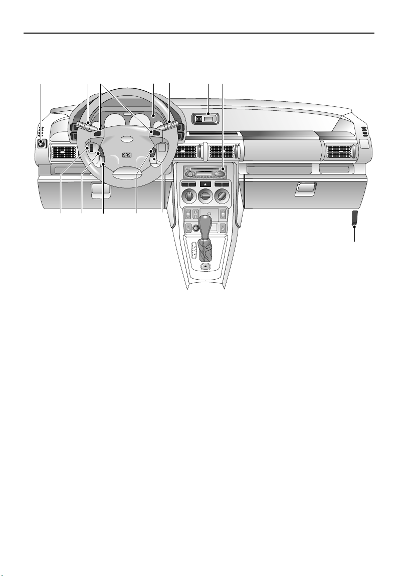
FACIA CONTROLS
Quick Guide
357
13 12 1011 9
H4069
1. Clock display
2. Audio system
3. Lighting and direction indicator controls
4. Instrument panel
5. Horn switches
6. Windshield wiper/washer controls
7. Exterior mirror control
2
146
RDS
FADE
BAL
CD TA
BAND
BASS
TREB
MENU
8. Hood release lever
9. Starter switch
10. Cruise control set and remote switches
11. Steering column adjustment lever
12. Remote audio controls
13. Instrument illumination control
8
NOTE: The precise specification and location of the controls may vary according to territorial
requirements and from model to model within the vehicle range.
8
Quick Guide
H
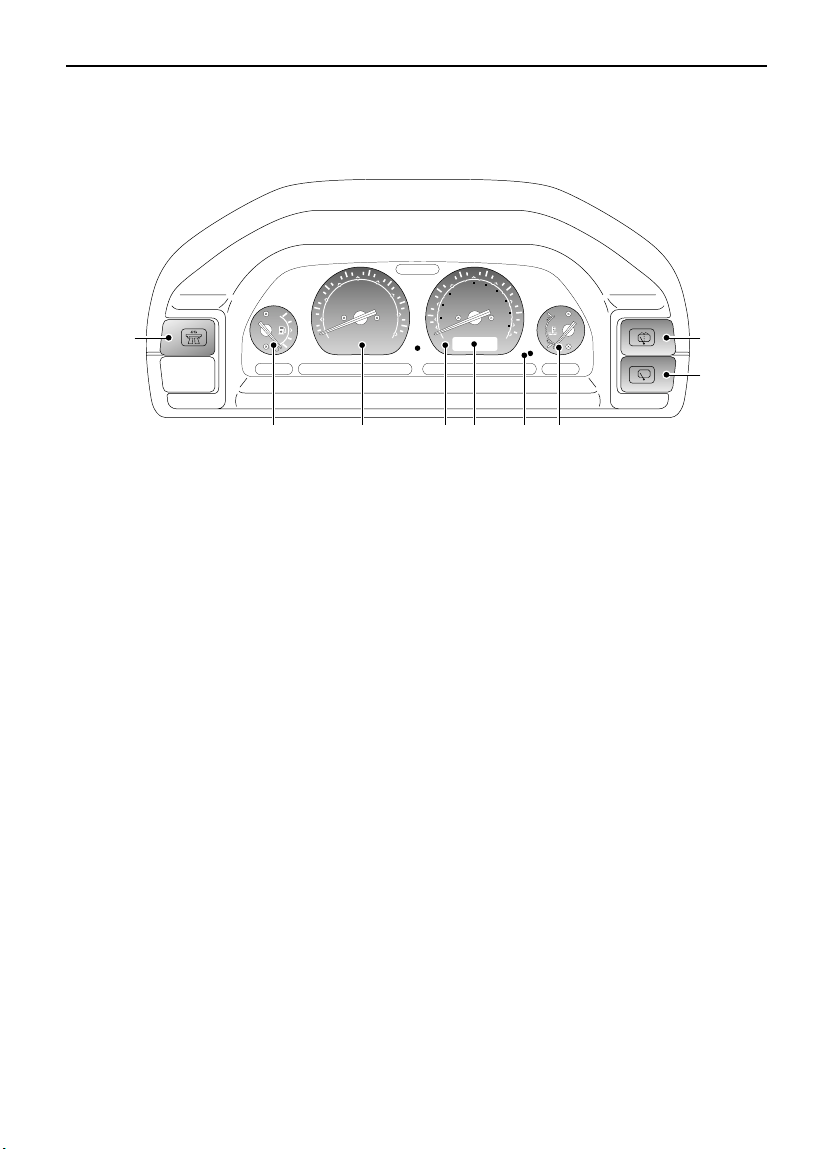
INSTRUMENT PANEL AND BINNACLE
SWITCHES
4
5
3
6
r/min x 1000
2
1
1
0
7
8
70
90
1
2
0
0
50
0
1
1
40
0
8
160
110
MPH km/h
0
6
0
3
0
4
20
10
1
8
0
200
1
3
0
2
2
0
8
9
4773
1. Cruise control master switch
2. Fuel gauge
3. Tachometer
4. Speedometer
6. Trip recorder reset/mode button
7. Coolant temperature gauge
8. Rear windshield wash/wipe switch
9. Rear windshield wiper switch
5. Digital display
NOTE: This is a brief overview of the instrument panel and binnacle switches. For a more detailed
description of each instrument, please refer to ‘INSTRUMENT PANEL’, page 59, and to find out more
about the rear windshield wiper and washer, refer to ‘REAR WINDSHIELD WIPER AND WASHER’,
page 67.
6543 72
9
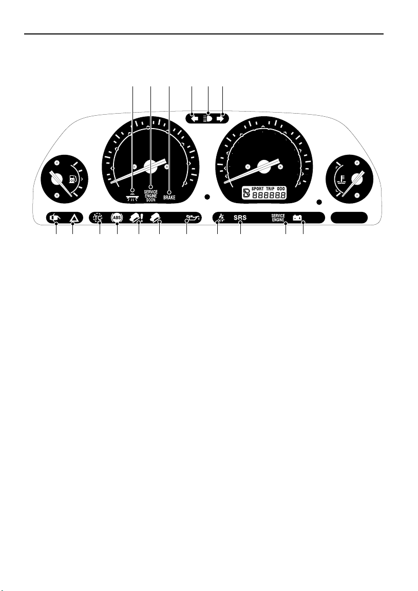
WARNING LIGHTS
Quick Guide
1 2 3 54 4
4
3
2
5
r/min x 1000
1
0
H4774
1. Cruise control (AMBER)
2. Service engine soon (AMBER).
3. Parking brake & brake system (RED)).
4. Direction indicators (GREEN).
5. Headlight high beam (BLUE).
6. Battery charging (RED).
7. Service engine
8. Supplemental restraint system - airbags
6
7
8
30
10
9. Seat belt reminder (RED).
10. Low oil pressure (RED).
11. Hill descent control (GREEN).
12. Hill descent control ‘failure’ (AMBER).
13. Anti-lock braking system (AMBER).
14. Traction control (AMBER).
15. Hazard warning lights (RED)
16. Door open (RED)
70
90
120
0
50
0
1
MPH km/h
140
160
110
180
200
130
220
80
0
6
40
20
78910111213141516 6
(RED).
NOTE: This is a brief overview of the warning lights, for more information concerning warning light
functionality, please refer to ‘INSTRUMENT PANEL’, page 59.
10
Quick Guide
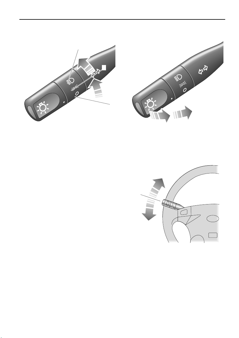
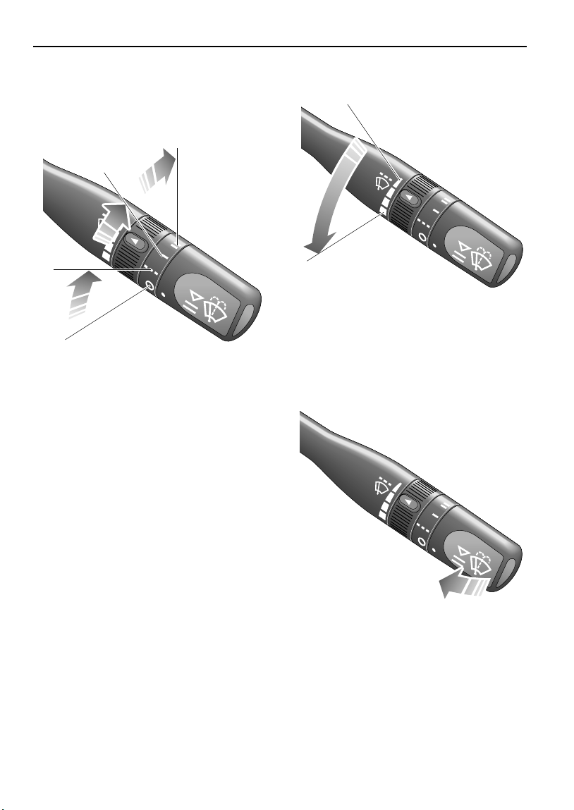
LIGHTS & INDICATORS
2
1
H3341
Side, tail and instrument panel lights
Turn lighting switch to position 1.
Headlights
Turn lighting switch to position 2.
Daytime running lights
The headlights illuminate automatically, when
the starter switch is turned to position ‘II’.
*
Headlight high and dipped beams
H3342
Pull the lever fully towards the steering wheel to
change headlight beams.
Direction indicators
H3340
Move the lever DOWN to indicate a LEFT turn,
and UP to indicate a RIGHT turn.
NOTE: For further information concerning
operation of the lights, please refer to
‘DIRECTION INDICATORS’, page 63.
11
Quick Guide
WIPERS & WASHERS
The wipers and washers will only operate when
the starter switch is turned to position ‘I’ or ‘II’.
3
2
1
H3345
Intermittent wipe
Turn switch to position 1.
Normal speed wipe
Turn switch to position 2.
Fast speed wipe
Turn switch to position 3.
Single wipe
Pull the lever down and release immediately.
Variable delay (intermittent wipe)
H3346
Rotate the inner switch to vary the delay
between wipes.
Windshield washers
NOTE: With the lever held down, the wipers will
operate at fast speed until the lever is released.
H3347
Pull the lever towards the steering wheel. The
windshield wipers will operate in conjunction
with the washers.
12
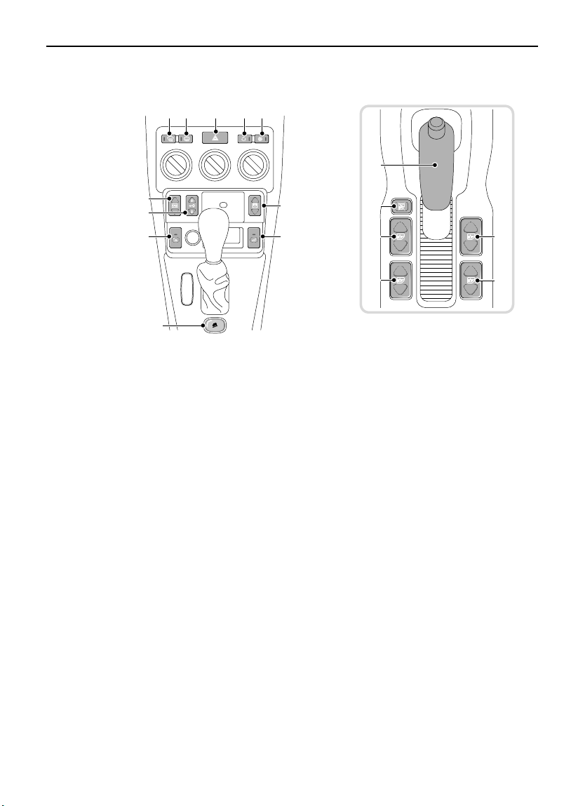
CENTER CONSOLE SWITCHES
21 43 5
Quick Guide
13
6
7
9
H4356
1. Heated front windshield*
2. Heated rear windshield
3. Hazard warning lights
4. Recirculated air supply
5. Air conditioning
6. Electric taildoor glass
7. Central door locking
10
*
8
9
12
11
11
8. Sunroof
9. Heated seats (2)*
10. Hill descent control
11. Electric windows (4)
12. Rear windows isolation switch
13. Parking brake
*
11
11
13
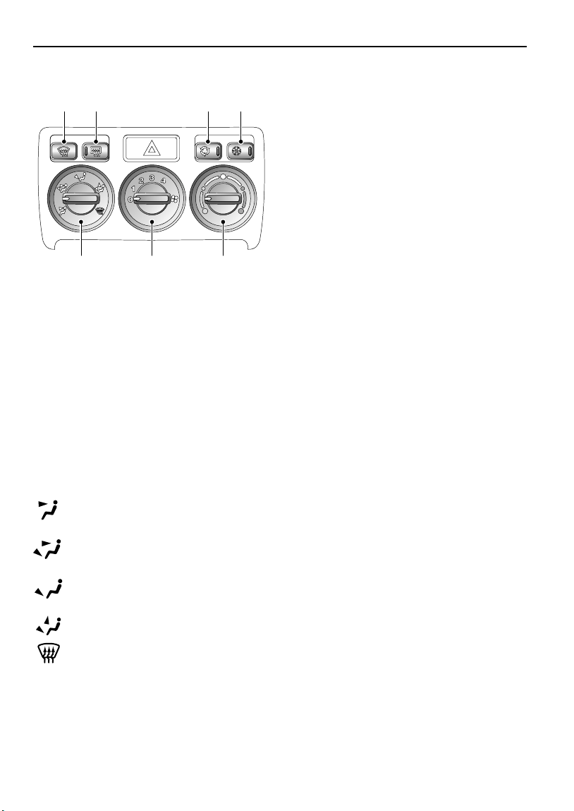
HEATER CONTROLS
Quick Guide
214
765
H3317A
1. Heated front windshield*
2. Rear windshield demister
3. Air recirculation button
4. Air conditioning
5. Air temperature control
6. Air blower control
7. Air distribution control
Air to face vents.
3
Air to face vents and foot outlets.
Air to foot outlets.
Air to foot outlets and windshield.
All air to windshield.
14
Quick Guide
TP
CD
Rad
Nav
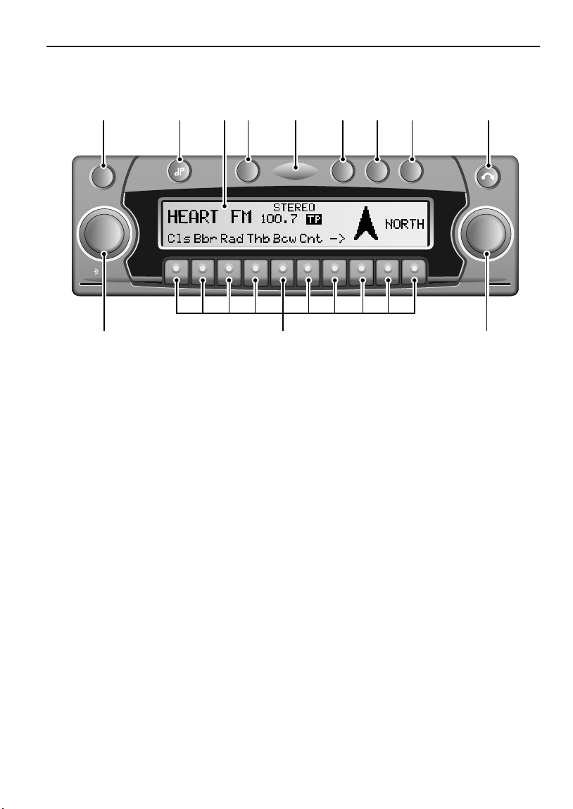
AUDIO/NAVIGATION SYSTEM CONTROLS
1 2 4 5 6 7 8 9
ON
Info
NAVISYS
ICE 1242
1. On/Off
2. Tone button
3. Display
4. Traffic programme button
5. Security light
3
TP
Rad
CD
NAVIGATION SYSTEM
Nav
1112 10
7. Radio mode selection button
8. Navigation mode selection button
9. Display/CD eject button
10. Right rotary control
11. Multifunction buttons
OK
6. CD mode selection button
12. Left rotary control
NOTE: For more information concerning the operation of your audio system, see your In-Car
Entertainment handbook.
15
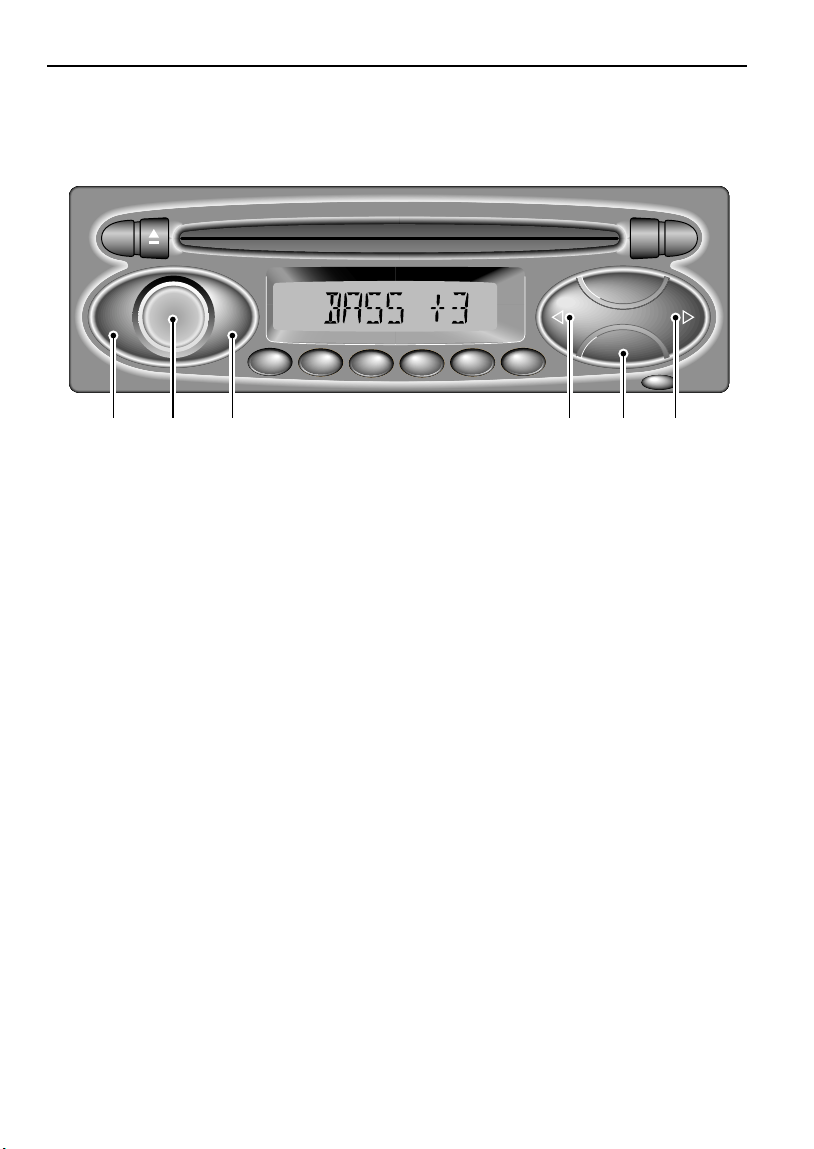
SOUND CONTROLS
RDS
FADE
BAL
ICE 1184
BASS
TREB
Quick Guide
1
2
34
i
CD
BAND
6
5
MENU
5 4312 5
1. On/off and volume control
2. Fader and balance control
4. Menu control (MENU)
5. Search controls (< >)
3. Bass and treble control
NOTE: For more information concerning the operation of your audio system, see your In-Car
Entertainment handbook.
16

Introduction
Introduction
REPORTING SAFETY DEFECTS . . . . . . . . . . . . . . 19
AUTO SAFETY HOTLINE . . . . . . . . . . . . . . . . . . . 19
WARNING LABELS ATTACHED TO THE VEHICLE 19
CALIFORNIA PROPOSITION 65 WARNING . . . . . 19
WARNINGS IN THIS HANDBOOK. . . . . . . . . . . . . 19
BEFORE YOU DRIVE . . . . . . . . . . . . . . . . . . . . . . 20
SYMBOLS USED . . . . . . . . . . . . . . . . . . . . . . . . . 20
PASSPORT TO SERVICE . . . . . . . . . . . . . . . . . . . 20
INFORMATION LABELS IN THE ENGINE
COMPARTMENT . . . . . . . . . . . . . . . . . . . . . . . . . 21
SUN VISOR LABELS . . . . . . . . . . . . . . . . . . . . . . 22
PASSENGER AIRBAG LABEL. . . . . . . . . . . . . . . . 22
ANTI-THEFT PRECAUTIONS . . . . . . . . . . . . . . . . 23
IN AN EMERGENCY. . . . . . . . . . . . . . . . . . . . . . . 23
BREAKING-IN . . . . . . . . . . . . . . . . . . . . . . . . . . . 24
17

18
Introduction
Introduction
Introduction
REPORTING SAFETY DEFECTS
If you believe that your vehicle has a defect
which could cause a crash, or could cause
injury or death, you should immediately
inform the National Highway Traffic Safety
Administration (NHTSA) in addition to
notifying Land Rover North America Inc.
If NHTSA receives similar complaints, it
may open an investigation and if it finds
that a safety defect exists in a group of
vehicles, it may order a recall and remedy
campaign.
CALIFORNIA PROPOSITION 65 WARNING
WARNING
Engine exhaust, some of its constituents and
certain vehicle components contain or emit
chemicals known to the State of California to
cause cancer and birth defects or other
reproductive harm. In addition, certain fluids
contained in vehicles and certain products of
component wear contain or emit chemicals
known to the State of California to cause
cancer, and birth defects or other
reproductive harm.
However, NHTSA cannot become involved
in individual problems between you, your
retailer or Land Rover North America.
AUTO SAFETY HOTLINE
To contact NHTSA, you may either call the
Auto Safety HOTLINE toll free at
1-800-424-9393 (or 202-366-0123 in the
Washington, D.C. area) or write to:
NHTSA, U.S. Department of
Transportation, Washington, DC 20590.
You can also obtain other information
about motor vehicle safety from the
HOTLINE.
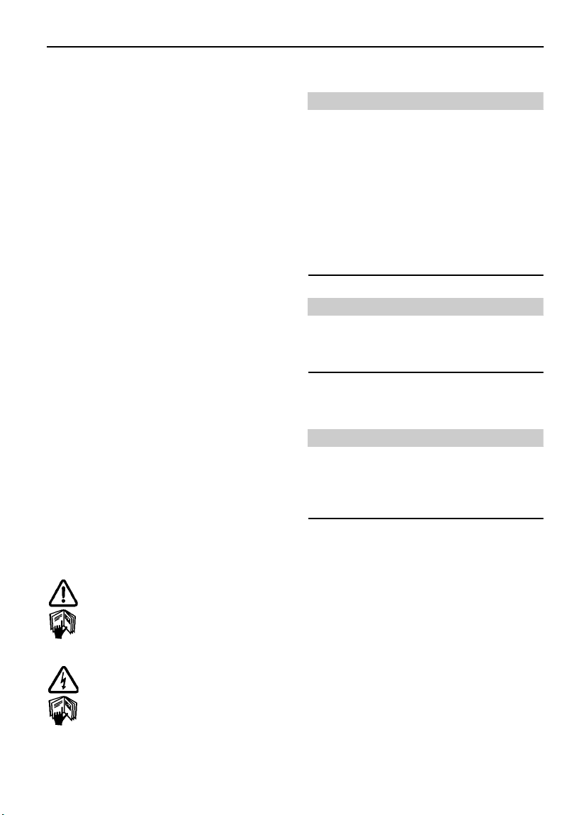
WARNING LABELS ATTACHED TO THE
VEHICLE
Warning labels attached to your
vehicle bearing this symbol mean: DO
NOT touch or adjust components until
you have read the relevant
instructions in the handbook.
Warning labels showing this symbol
indicate that the ignition system
utilizes very high voltages. DO NOT
touch any ignition components while
the starter switch is turned on!
WARNING
Battery posts, terminals and related
accessories contain lead and lead
compounds. Wash hands after handling.
WARNINGS IN THIS HANDBOOK
WARNING
Safety warnings are included in this
handbook. These indicate a procedure which
must be followed precisely in order to avoid
the possibility of personal injury.
19

Introduction
BEFORE YOU DRIVE
Your Freelander has a higher ground
clearance and, hence, a higher center of
gravity than ordinary passenger cars, to
enable the vehicle to perform in a wide
variety of off-road applications. An
advantage of the higher ground clearance
is a better view of the road, allowing you
to anticipate problems.
The vehicle is not designed for cornering
at the same speed as conventional
passenger cars any more than a
low-slung sports car is designed to
perform satisfactorily under off-road
conditions. If at all possible, avoid sharp
turns or abrupt maneuvers. As with other
vehicles of this type, failure to operate
the Freelander correctly may result in
loss of control or vehicle rollover. For
important safety information, be sure to
read the ‘On-Road’ and ‘Off-Road’ driving
guidelines given later in this handbook.
SYMBOLS USED
The following symbols used within the
handbook call your attention to specific types of
information.
PASSPORT TO SERVICE
The Passport to Service book included in your
literature pack contains important vehicle
identification information, details of your
entitlement under the terms of the Land Rover
warranty, as well as useful consumer advice.
Most important of all, however, is the section
on maintenance. This outlines the servicing
requirements for your vehicle and also includes
the service record slips, which the retailer
should sign and stamp to certify that routine
services have been carried out.
This recycling symbol identifies items
that must be disposed of safely in order to
prevent unnecessary damage to the
environment.
This symbol identifies features that can be
adjusted or disabled/enabled by a Land
Rover retailer
*An asterisk appearing within the text,
identifies features or items of equipment that
are either optional, or are only fitted to some
vehicles in the model range.
20
Introduction
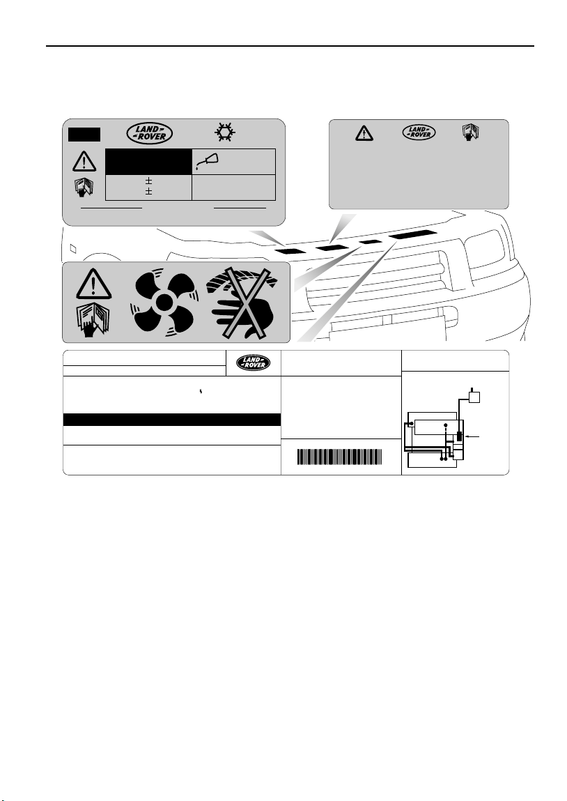
INFORMATION LABELS IN THE ENGINE
COMPARTMENT
A/C
R134a
CF3 CH2F
(
(
15 oz 1oz
SYSTEM TO BE SERVICED BY QUALIFIED PERSONNEL.
(
CAUTION
SAE
J
PAG OIL
ND 8
120ml430 g 25 g
4.1 fl oz
639
LAND ROVER
VEHICLE EMISSION CONTROL INFORMATION
TEST GROUP : 3LRXT02.5002
DISPLACEMENT : 152 CU IN./2.5 LITER
EVAP.FAMILY : 3LRXR0124002 ( 86.130-96 procedures)
EXHAUST ECS : SFI/2TWC/2HO2S(2)
SPARK PLUG GAP : 0.038-041 IN. / 0.95-1.05 MM
CERTIFICATION FUEL : CALIFORNIA PHASE 2 GASOLINE
NO ENGINE ADJUSTMENT REQUIRED
CATALYST
THIS VEHICLE CONFORMS TO U.S. EPA NLEV REGULATIONS
APPLICABLE TO 2003 MODEL YEAR NEW LEV LIGHT-DUTY TRUCKS
AND CALIFORNIA REGULATIONS APPLICABLE TO 2003 MODEL
YEAR NEW LEV LIGHT-DUTY TRUCKS
H4560
Various labels are attached to the hood locking
platform, the number, position and content of
which may vary from model to model. The
following list is provided as a guide:
• Keep clear of rotating engine parts
• Air conditioning label
• Emission control label
• Engine oil label
USE ONLY APPROVED
5W-40 OR 5W-50 FULL
SYNTHETIC ENGINE OIL
(
PERMANENT FOUR WHEEL DRIVE
OR TRACTION CONTROL EQUIPPED
VEHICLES MUST BE CONDUCTED ON
A FOUR WHEEL DRIVE SPEED
SYNCHRONISED DYNAMOMETER
OTHERWISE NONLOADED TEST
PROCEDURE MUST BE PERFORMED
FOR SPECIFICATIONS
EPA APPROVED
I/M TESTING EXEMPTION
LOADED I/M TESTING OF
OBD II CERTIFIED
252QGFFE
CAUTION / ATTENTION
UTILISER UNIQUEMENT DE L'HUILE
MOTOR SYTHETIQE APPROUVEE
5W-4- OU 5W-50
SEE HANDBOOK
CONSULTER LE MANUEL
DU CONDUCTEUR POUR
LES SPECIFICATIONS
VACUUM ROUTING DIAGRAM
FUEL TANK
CHARCOAL
CANISTER
PURGE
VALVE
BAC000801
21
Introduction
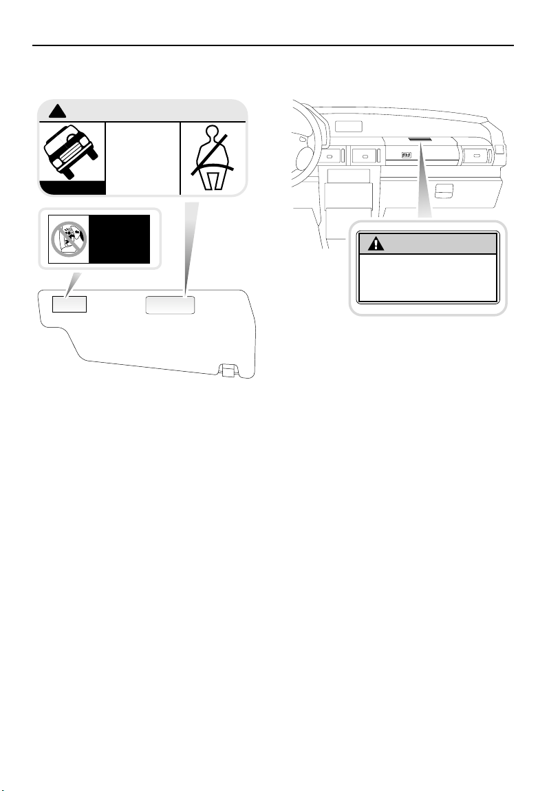
SUN VISOR LABELS
WARNING:
!
H4032
Take note of the warnings concerning the
airbag SRS and risk of vehicle rollover.
HIGHER ROLLOVER RISK
Avoid Abrupt Maneuvers
and Excessive Speed.
Always Buckle Up.
See Owner's Manual
For Further Information
AIR BAG AND
ROLLOVER
WARNINGS
FLIP VISOR OVER
PASSENGER AIRBAG LABEL
WARNING
Children Can Be KILLED or INJURED
by Passenger Air Bag
The back seat is the safest place for children 12 and under.
Make sure all children use seat belts or child seats.
H4761
Take note of the warning concerning the airbag
SRS and the safe seating of small children.
22

Introduction
ANTI-THEFT PRECAUTIONS
While it may be difficult to deter the
‘professional’ car thief, the majority of thefts are
carried out by unskilled opportunists.
Therefore, take vehicle security very seriously
and ALWAYS adopt this simple ‘four point’ drill
whenever you leave your vehicle - even for just
a few minutes:
1. Fully close all the windows (and the
sunroof).
2. Remove your valuable belongings (or hide
them out of sight).
3. Remove the starter key.
4. Superlock the vehicle using the remote
handset.
Thieves are attracted by ‘vulnerable’ vehicles.
Even if you have followed the ‘four point’ drill,
there is still much you can do to make your
vehicle a less inviting target.
BE SAFE - NOT SORRY!
• Park where your vehicle can be easily seen
by householders and passers-by.
• At night, park in well lit areas and avoid
deserted or dimly-lit side streets.
• NEVER leave the keys in the vehicle.
• Do not keep important documents (or spare
keys) in the vehicle - these are a real bonus
for the thief.
IN AN EMERGENCY
IMPORTANT INFORMATION
Remember the breakdown safety code
If a breakdown occurs while travelling:
• Wherever possible, consistent with
road safety and traffic conditions, the
vehicle should be moved off the main
thoroughfare, preferably onto the
shoulder. If a breakdown occurs on a
freeway, pull well over to the inside of
the shoulder.
• Switch on hazard lights.
• If possible, position a warning triangle
or a flashing amber light at an
appropriate distance from the vehicle to
warn other traffic of the breakdown,
(note the legal requirements of some
areas).
• Consider evacuating passengers
through the doors facing away from the
traffic, to a safe area away from the
vehicle as a precaution in case your
Freelander is accidentally struck by
another vehicle.
23

Introduction
BREAKING-IN
Proper breaking-in will have a direct bearing on
the reliability and smooth running of your
vehicle throughout its life.
In particular, the engine, gearbox, brakes and
tires need time to ‘bed-in’ and adjust to the
demands of everyday motoring. During the first
600 miles (1000 km), it is essential to drive with
consideration for the breaking-in process and
heed the following advice:
• LIMIT maximum road speed to 70 mph
(110 km/h) or 3,000 rev/min. Initially, drive
the vehicle on a light throttle and only
increase engine speeds gradually once the
breaking-in distance has been completed.
• DO NOT operate at full throttle or allow the
engine to labour in any gear.
• AVOID fast acceleration and heavy braking
except in emergencies.
After the breaking-in distance has been
completed, engine speeds may be gradually
increased.
24

Controls & Instruments
Locks & Alarm
KEYS AND HANDSETS. . . . . . . . . . . . . . . . . . . . . 27
ALARM SYSTEM . . . . . . . . . . . . . . . . . . . . . . . . . 27
LOCKING THE VEHICLE AND ARMING
THE ALARM. . . . . . . . . . . . . . . . . . . . . . . . . . . . . 28
CHILD-PROOF LOCKS . . . . . . . . . . . . . . . . . . . . . 31
ENGINE IMMOBILISATION . . . . . . . . . . . . . . . . . 31
DOOR LOCKING CUT-OFF SWITCH . . . . . . . . . . . 32
REMOTE HANDSET BATTERY . . . . . . . . . . . . . . . 33
ALARM OR HANDSET DIFFICULTIES. . . . . . . . . . 34
Taildoor
OPENING AND CLOSING. . . . . . . . . . . . . . . . . . . 35
Seats
SEATING . . . . . . . . . . . . . . . . . . . . . . . . . . . . . . . 36
FOLDING THE REAR SEATS. . . . . . . . . . . . . . . . . 38
Seat Belts
SEAT BELT SAFETY . . . . . . . . . . . . . . . . . . . . . . . 40
WEARING SEAT BELTS CORRECTLY. . . . . . . . . . 41
FRONT SEAT BELT PRE-TENSIONERS . . . . . . . . 43
CARE & MAINTENANCE OF SEAT BELTS. . . . . . . 44
Child Restraints
CHILD RESTRAINTS FOR SMALL CHILDREN AND
BABIES . . . . . . . . . . . . . . . . . . . . . . . . . . . . . . . . 45
CHILD RESTRAINTS FOR LARGER CHILDREN . . 45
TETHER STRAP ANCHORAGES. . . . . . . . . . . . . . 47
‘LATCH’ TYPE CHILD RESTRAINTS. . . . . . . . . . . 48
Airbag SRS
AIRBAG SUPPLEMENTAL RESTRAINT SYSTEM
(SRS). . . . . . . . . . . . . . . . . . . . . . . . . . . . . . . . . . 49
HOW THE AIRBAG SRS WORKS . . . . . . . . . . . . . 51
CHILD SEATS. . . . . . . . . . . . . . . . . . . . . . . . . . . . 53
SERVICE INFORMATION . . . . . . . . . . . . . . . . . . . 53
Steering Column
STEERING COLUMN ADJUSTMENT . . . . . . . . . . 55
Instruments
INSTRUMENT PANEL . . . . . . . . . . . . . . . . . . . . . 56
Warning Lights
INSTRUMENT PANEL . . . . . . . . . . . . . . . . . . . . . 59
25

Audible Warnings
AUDIBLE WARNINGS . . . . . . . . . . . . . . . . . . . . . 62
Lights & Indicators
DIRECTION INDICATORS . . . . . . . . . . . . . . . . . . 63
LIGHTS . . . . . . . . . . . . . . . . . . . . . . . . . . . . . . . . 63
HAZARD WARNING LIGHTS. . . . . . . . . . . . . . . . 64
Wipers & Washers
OPERATING . . . . . . . . . . . . . . . . . . . . . . . . . . . . 65
WINDSHIELD WIPERS . . . . . . . . . . . . . . . . . . . . 65
WINDSHIELD WASHERS . . . . . . . . . . . . . . . . . . 66
REAR WINDSHIELD WIPER AND
WASHER. . . . . . . . . . . . . . . . . . . . . . . . . . . . . . . 67
Horn
HORN . . . . . . . . . . . . . . . . . . . . . . . . . . . . . . . . . 68
Mirrors
EXTERIOR MIRRORS . . . . . . . . . . . . . . . . . . . . . 69
INTERIOR MIRROR . . . . . . . . . . . . . . . . . . . . . . 70
VANITY MIRROR . . . . . . . . . . . . . . . . . . . . . . . . 70
Windows
ELECTRIC WINDOW CONTROLS . . . . . . . . . . . . 71
ELECTRIC TAILDOOR GLASS. . . . . . . . . . . . . . . 72
Sunroof
ELECTRIC SUNROOF . . . . . . . . . . . . . . . . . . . . . 73
SUN VISOR. . . . . . . . . . . . . . . . . . . . . . . . . . . . . 86
ASHTRAY . . . . . . . . . . . . . . . . . . . . . . . . . . . . . . 86
CIGAR LIGHTER . . . . . . . . . . . . . . . . . . . . . . . . . 87
AUXILIARY POWER SOCKET . . . . . . . . . . . . . . . 87
Loadspace Cover
LOADSPACE COVER . . . . . . . . . . . . . . . . . . . . . . 88
In-Car Telephones
IN-CAR TELEPHONES. . . . . . . . . . . . . . . . . . . . . 89
In-Car Entertainment
RADIO/CASSETTE PLAYER. . . . . . . . . . . . . . . . . 90
RADIO AERIAL . . . . . . . . . . . . . . . . . . . . . . . . . . 90
REMOTE AUDIO CONTROLS. . . . . . . . . . . . . . . . 90
NAVIGATION SYSTEM . . . . . . . . . . . . . . . . . . . . 90
Targa Roof
TARGA ROOF . . . . . . . . . . . . . . . . . . . . . . . . . . . 74
Heating & Ventilation
VENTILATION . . . . . . . . . . . . . . . . . . . . . . . . . . . 76
HEATER CONTROLS. . . . . . . . . . . . . . . . . . . . . . 77
USING YOUR HEATER . . . . . . . . . . . . . . . . . . . . 78
FACE LEVEL VENTS . . . . . . . . . . . . . . . . . . . . . . 79
AIR CONDITIONING . . . . . . . . . . . . . . . . . . . . . . 80
HEATED FRONT SEATS. . . . . . . . . . . . . . . . . . . . 81
Interior Equipment
COURTESY & MAP READING LIGHTS . . . . . . . . 82
LUGGAGE COMPARTMENT LIGHT. . . . . . . . . . . 82
CLOCK . . . . . . . . . . . . . . . . . . . . . . . . . . . . . . . . 82
GLOVEBOX . . . . . . . . . . . . . . . . . . . . . . . . . . . . . 83
DRIVER'S STORAGE AREA. . . . . . . . . . . . . . . . . 83
PASSENGERS’ STORAGE . . . . . . . . . . . . . . . . . . 84
DRINKS STOWAGE. . . . . . . . . . . . . . . . . . . . . . . 84
CUP HOLDERS . . . . . . . . . . . . . . . . . . . . . . . . . . 85
26
Locks & Alarm
Controls & Instruments
Locks & Alarm
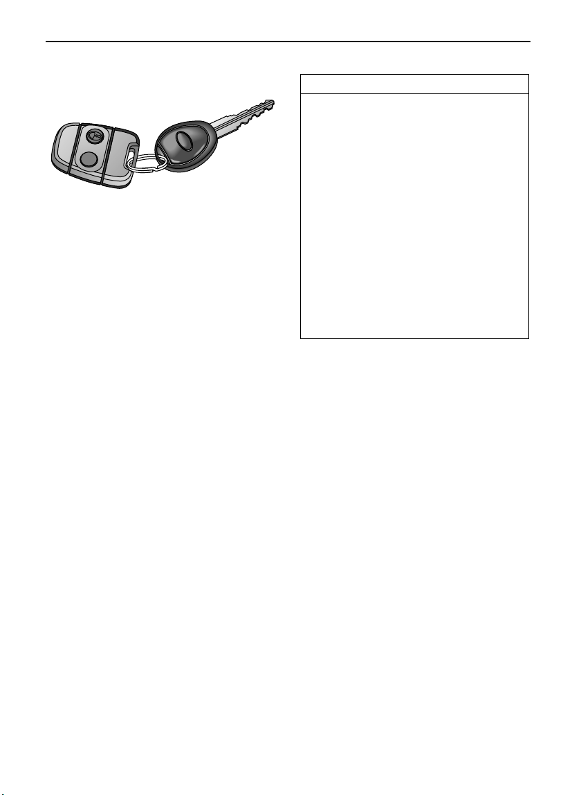
KEYS AND HANDSETS
H3519A
You have been supplied with a pair of identical
keys and two remote control handsets.
Keep the spare key in a safe place - NOT IN THE
VEHICLE!
The keys supplied with your vehicle are
programmed to the vehicle's security system they CANNOT be reprogrammed and the engine
cannot be started without a valid programmed
key. If a key is lost or broken, a replacement can
be ordered only from a Land Rover retailer.
NOTE: Land Rover retailers do not stock spare
keys, time has to be allowed for replacements
to be programmed to your security system and
then delivered to the retailer.
If you lose a key, contact your Land Rover
retailer; a key reported lost will be deactivated.
If the key is later recovered, your Land Rover
retailer can have it reactivated.
IMPORTANT INFORMATION
The handset complies with part 15 of the
FCC rules. Operation is subject to the
following conditions:
• This device may not cause harmful
interference.
• This device must accept any
interference received, including
interference that may cause undesired
operation. This applies to both alarm
receivers and transmitters.
Any changes or modifications to the
handset not expressly approved by the
manufacturer or Land Rover North
America, could void the user’s authority to
operate the equipment.
ALARM SYSTEM
Your vehicle is fitted with a sophisticated
electronic anti-theft alarm and engine
immobilisation system. In order to ensure
maximum security and minimum
inconvenience, you are strongly advised to gain
a full understanding of the alarm system by
thoroughly reading this section of the
handbook.
27
Locks & Alarm
LOCKING THE VEHICLE AND ARMING
THE ALARM
Before locking the vehicle and arming the
alarm, ensure that all doors (including taildoor),
windows, sunroof and hood apertures are
securely closed.
There are three methods for securing your
vehicle:
• ‘Superlocking’ using the handset -
(recommended high security method).
• ‘Superlocking’ using the key.
• Locking using the key.
IMPORTANT INFORMATION
• FOR MAXIMUM SECURITY ALWAYS
SUPERLOCK THE VEHICLE USING THE
REMOTE HANDSET
Using the remote handset
Locking
With the remote handset:
Press the lock (padlock symbol) button once.
Each time the vehicle is locked using the
handset, a coded signal is transmitted to a
receiver inside the vehicle, which activates the
following security features:
• the central door locking system (all the door
locks are activated).
• the perimetric alarm (protects the door,
taildoor, and hood apertures).
Pressing the lock (padlock symbol) a second
time within one second of the first action
activates:
• ‘Superlocking’ - the door locks cannot be
operated from inside the vehicle.
With both levels of locking, if the doors lock
correctly, the direction indicator lights flash
three times to confirm that the vehicle is secure
and the anti-theft alarm indicator light (in the
instrument panel) will start to flash rapidly.
Once armed, the alarm will sound if any door is
opened.
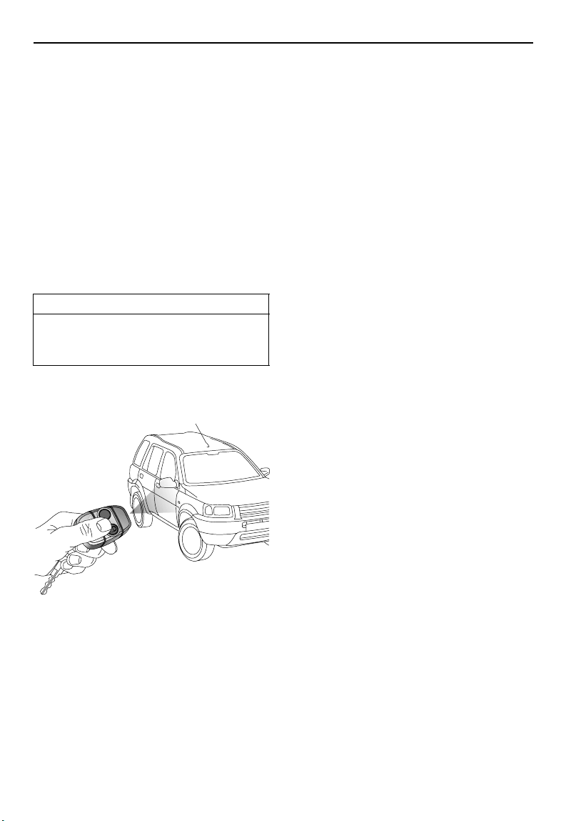
With the key:
Insert the key and turn the door lock clockwise.
Turning the key ONCE activates the following:
• all doors locked (not superlocked)
• perimetric alarm activated (protects the
doors, hood and taildoor)
H3297
While it is not necessary to point the handset at
the vehicle, the handset must be within range of
the vehicle when a button is pressed. Note that
the operating range may vary depending upon
handset battery condition and may sometimes
be limited by physical and geographical factors
beyond your control. From a security point of
view, it may not be wise to unlock unless you
are within a few feet of the vehicle.
Turning the key TWICE within 1 second
activates, in addition to the above:
• Superlocking
If the doors lock correctly, the direction
indicators flash three times to confirm that the
vehicle is secure and the anti-theft alarm
indicator light (in the instrument panel) will
start to flash rapidly.
NOTE: The engine will automatically be
immobilised after the starter switch has been
turned off.
28
Locks & Alarm
Superlocking
Provided all the doors are fully closed, the
Superlocking feature is activated automatically
whenever the vehicle is locked by pressing the
padlock symbol on the remote handset twice
within one second. Superlocking immobilises
the interior door handles, thereby preventing an
intruder from gaining entry by smashing a
window and reaching inside the vehicle to
operate the door handles.
WARNING
For safety, NEVER use Superlocking if
passengers are to remain inside the vehicle in an emergency they would not be able to
escape.
Mislock
If one of the doors, taildoor or hood is not
properly closed when the alarm is armed, a
mislock occurs (the horn will sound a warning).
The alarm will still be armed and the engine
immobilised, but the open aperture will not be
protected. If the appropriate aperture is then
closed, the alarm will fully arm without the need
to press the lock button again unless the
driver's door is open, in which case the alarm
will be fully armed by pressing the lock button
again.
If the taildoor glass is left open when the alarm
is armed, the horn will sound as a reminder, but
the vehicle will be locked and alarmed as
normal. The taildoor glass can be closed from
outside the vehicle using the starter key in the
taildoor (see ‘Raising and lowering’, page 72).
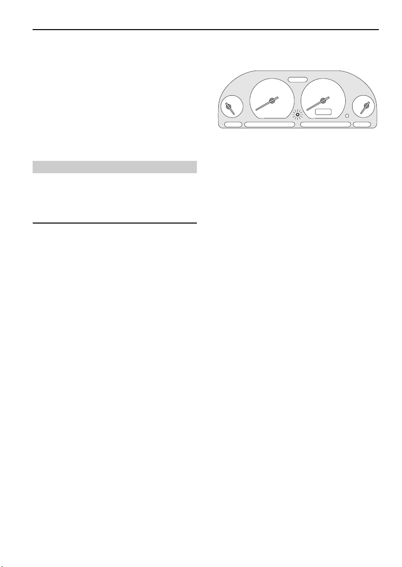
Anti-theft alarm indicator light
H3298
After locking, the RED indicator light on the
instrument panel flashes rapidly while the alarm
is arming itself.
After approximately 10 seconds, the indicator
light adjusts to a slower frequency, and
continues to flash as an anti-theft deterrent
until the alarm is disarmed.
Unlocking
With the remote handset:
If your vehicle is configured with the Single
Point Entry security feature, and was locked
with the handset, the handset unlocks the
vehicle in two stages:
• Press the unlock (Land Rover) button once
to disarm the alarm and unlock the driver's
door only (see ‘Single point entry’,
page 30).
• Press the unlock button twice to disarm the
alarm and unlock ALL the doors.
If your vehicle is not configured with Single
Point Entry, all the doors will unlock at the first
press.
In either case, the direction indicators flash
once and the interior lights illuminate.
With the key:
Turn the key towards the front of the vehicle.
The alarm will be fully disarmed. To remobilise
the engine, the key must be inserted into the
starter switch.
29
Locks & Alarm
If the alarm sounds
If the alarm is triggered, it will sound for
approximately 30 seconds before switching
itself off and can be triggered up to ten times
in total before needing to be reset.
To silence the alarm, press either handset
button, or operate the door locks using the key
in the driver's door.
Single point entry
This is a personal security feature, which
enables the driver's door only to be unlocked,
leaving the other doors in a locked state. It can
be operated by the remote handset as follows:
Press the unlock button once to unlock the
driver's door, press a second time to unlock the
remaining doors and taildoor.
Single point entry can be configured by a
Land Rover retailer.
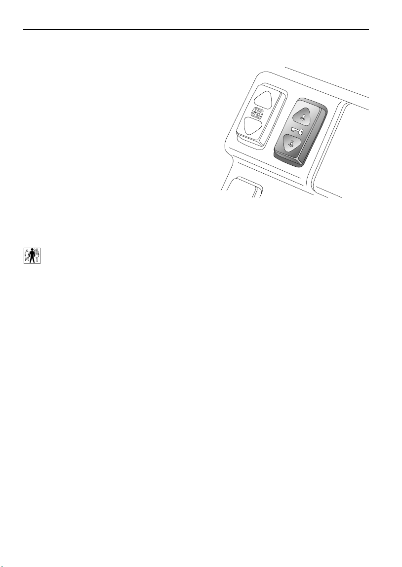
Interior locking switch
H3334
This is a personal security feature which allows
the driver to lock (or unlock) all the doors from
inside the vehicle (while driving or with the
vehicle stationary). Press the lower part of the
switch to lock (the alarm will not be armed),
and the upper part to unlock.
NOTE: If interior locking has been activated,
pull the interior door handle once to unlock, and
twice to open the door.
Door handles and door sill locking buttons
From inside the vehicle, each door can be
individually locked by depressing the
appropriate door sill button. However, doors
cannot be unlocked by raising the sill button.
Use the door handles to unlock, as follows:
• First operation of the door handle unlocks
the door.
• Second operation of the door handle opens
the door.
NOTE: The door handles will not open the doors
if the vehicle has been superlocked (see
‘Superlocking’, page 29)
30

Locks & Alarm
CHILD-PROOF LOCKS
H4034
Move the lever on the rear doors down (see
inset) to engage.
With the child-proof locks engaged, the rear
doors cannot be opened from inside the
vehicle, thereby avoiding the risk of a door
being opened accidentally while the vehicle is
moving.
ENGINE IMMOBILISATION
Engine immobilisation is an important aspect of
the security system and is designed to
safeguard the vehicle from theft, should the
driver forget to lock the doors. Engine
immobilisation prevents the engine from being
started unless a valid key is inserted into the
starter switch, and occurs automatically after
the starter switch has been turned off.
The engine is re-mobilised by a signal
transmitted from a transponder contained
within the key head, to the starter switch. This
occurs automatically whenever a valid key is
inserted into the starter switch and turned to
position ‘I’.
CAUTION: DO NOT keep more than one starter
key, or keys from other vehicles, or gas station
speed payment devices on the same key ring:
the engine will not re-mobilise automatically.
WARNING
To avoid injury or even death, NEVER leave
children unsupervised in the vehicle.
31

Locks & Alarm
DOOR LOCKING CUT-OFF SWITCH
H3996
An inertia switch, which operates when the
starter switch is in position ‘II’, prevents the
doors from centrally locking (or, if the doors are
already locked, unlocks them) in the event of an
accident or sudden impact. If this occurs,
central locking will be inhibited until either:
• the starter switch is turned off and the
driver’s door has been opened and closed,
or:
• the driver’s door has been opened and
closed, and the inertia switch is reset.
The inertia switch is located inside the engine
compartment on the left hand side, beneath,
and to the rear of, the engine compartment fuse
box (a label attached to the bulkhead will assist
in locating the switch). The switch must be
reset before the engine can be restarted. Reset
the switch by pressing the rubber top (arrowed
in illustration).
This will also reset the fuel system, see ‘FUEL
CUT-OFF SWITCH’, page 100).
WARNING
ALWAYS check for fuel leaks before resetting
the switch! Activating the switch when the
fuel system has been damaged (evidenced by
fuel leakage or odor) will cause additional
fuel leakage increasing the risk of fire.
32

Locks & Alarm
REMOTE HANDSET BATTERY
The battery should last for approximately three
years dependent upon use. When the battery
needs replacing it will be apparent from the
following symptoms:
• A gradual deterioration in range and
performance.
• The alarm buzzer and the anti-theft alarm
indicator light will double bleep/flash every
second, for ten seconds, after the alarm is
disarmed and driver's door opened.
It is recommended that you fit a Land Rover
STC 4080 or a Panasonic CR2032 replacement
battery (available from a Land Rover retailer).
CAUTION: The handset contains delicate
electronic circuits and must be protected from
impact and water damage, high temperatures
and humidity, direct sunlight and the effects of
solvents, waxes and abrasive cleaners.
Battery replacement
3. Press and hold each button in turn for at
least five seconds (this will drain any
residual power from the handset).
4. Fit the new battery, ensuring that correct
polarity is maintained (‘+’ side facing up).
Finger marks will adversely affect battery
life; if possible, avoid touching the flat
surfaces of the battery and wipe them
clean before fitting.
5. Press the two halves of the handset firmly
together and ensure that both halves are
fully joined to prevent dirt or moisture
from entering the handset.
6. Resynchronise the handset.
The handset is now ready for use.
Handset resynchronisation
If the handset fails to lock or unlock the car, this
may be because the coded signal transmitted
by the handset, and the signal expected by the
alarm control unit, are no longer synchronised.
To resynchronise the handset, operate either
button of the handset at least five times in quick
succession (in close proximity to the vehicle).
3518
1. Carefully prise the handset apart, start
from the keyring end using a small coin or
screwdriver. Avoid damaging the seal
between the two halves of the case and DO
NOT allow dirt or moisture to get inside
the handset.
2. Slide the battery out of its clip, taking care
to avoid touching the circuit board or the
contact surfaces of the clip.
33

Locks & Alarm
ALARM OR HANDSET DIFFICULTIES
Alarm goes off unexpectedly. Ensure all windows, doors, hood and sunroof
are closed.
Vehicle will not start. Press unlock button on handset. If it still will not
start, consult your Land Rover retailer.
Hazard lights don't flash when alarm is
armed.
Doors unlock and hazard lights start to
flash when vehicle is in motion.
Ensure all doors and the hood are fully closed.
The inertia switch has been triggered - see
‘DOOR LOCKING CUT-OFF SWITCH’, page 32. If
fault continues, consult your Land Rover
retailer.
34

Taildoor
Taildoor
OPENING AND CLOSING
H2317
Opening the taildoor
When the release catch is pulled (as shown in
illustration), the taildoor lock is released in two
phases:
1. the taildoor glass drops clear of its
retaining channel.
2. the electronic door latch is released and
the door can be opened.
Initially, the door opens approximately half way
until resistance is felt; this prevents the door
swinging fully open and possibly hitting an
obstruction, yet still enables access in a
situation where there is not enough room to
open the door fully. Push against resistance to
open the door fully.
WARNING
You are advised NOT to carry loads which
require driving with the taildoor or taildoor
window open - poisonous fumes will be drawn
into the vehicle! If driving the vehicle in this
condition is unavoidable, switch the heater to
face level vents with all vents open, close the
sunroof and windows and turn the air blower
to position 4.
Closing
CAUTION: When closing the taildoor, push on
the handle - NOT on the taildoor glass.
Load carrying
Long loads should be carried on the roof rack.
If it is necessary to carry a load that protrudes
through the taildoor window aperture, the
weight of the load must NOT rest on the glass.
Damage to the glass or window mechanism
may occur.
NOTE: The taildoor latch will not operate if the
glass is frozen to the door seals, as the glass
needs to drop slightly before the door can be
opened. Defrost the glass first.
35

Seats
Seats
SEATING
WARNING
It is extremely dangerous to ride in the cargo
area, inside or outside the vehicle. In a
collision, people riding in these areas are
more likely to be seriously injured or killed.
Do not allow people to ride in any area of your
vehicle that is not equipped with seats and
safety belts. Be sure everyone in your vehicle
is in a seat and using a safety belt properly.
SITTING CORRECTLY
o
max. 30
H4691
• Do not move the front seat too close to the
instrument panel. The driver shou ld hold the
steering wheel with slightly bent arms. The
legs should also be slightly bent so that the
pedals can be pressed to the floor.
• The seat belt should rest in the center of the
shoulder. The lap part should fit tightly
across the hips and not on the stomach.
FRONT SEAT ADJUSTMENT
WARNING
To avoid the risk of loss of control and
personal injury, DO NOT adjust the driver's
seat or head restraint while the vehicle is in
motion.
DO NOT travel with the seat backs reclined
rearwards more than 30 degrees. Optimum
benefit is obtained from the seat belt, with the
backrest angle set to 25 degrees from the
upright (vertical).
An inflating airbag can cause facial abrasions
and other injuries. The injurious effects of
airbag inflation can be minimised by ensuring
that driver and passenger are seated
correctly, with the seat moved back as far as
is practical, and the seat belts worn correctly.
The seats, head restraints, seat belts and
airbags all contribute to the protection of the
occupants. Optimal use of these components
will give you more protection. Therefore,
observe the following points:
• Sit in the most upright position with the
base of your spine as far back as possible
and the backrest not reclined more than
30 degrees.
• Adjust the head restraints so that the top of
the head restraint is level with the upper
portion of the head.
Forward/backward adjustment
Lift the lever (1) and slide the seat into position.
Make sure the seat is locked in position before
driving.
Backrest adjustment
Rotate the handwheel (2) to adjust.
Lumbar support adjustment
(Driver's seat only)
Rotate the handwheel (3) to increase or
decrease support to the lumbar region of the
back.
36

Seats
4
5
1
H4033
Head restraint adjustment
WARNING
Head restraints are designed to support the
back of the head (NOT THE NECK), and to
restrain rearward movement of the head in
the event of a collision. The restraint must be
positioned level with the head to be effective.
DO NOT drive or carry passengers with the
head restraints removed from occupied seats,
or adjust the head restraints while the vehicle
is in motion.
After replacing a head restraint, turn the
right-hand mounting clockwise.
Rear seats
For information on folding the rear seats, refer
to ‘FOLDING THE REAR SEATS’, page 38.
Heated front seats
For information on the operation of the front
seat heaters, refer to ‘HEATED FRONT SEATS*’,
3
page 81.
*
2
Failure to have the head restraint installed
and properly positioned will increase the
potential for serious injuries.
Raise or lower the restraint (4), until the
cushion is level with the back of the head.
Head restraint removal
Turn the right-hand mounting (5) a quarter turn
anti-clockwise and pull the restraint upwards.
37

Seats
FOLDING THE REAR SEATS
On vehicles not fitted with 60/40 split rear seats
the whole seat can be folded forwards to
increase luggage space. On vehicles fitted with
60/40 split rear seats, either or both parts of the
seat can be folded.
NOTE: Before folding the rear seats, ensure that
the center rear seat belt is unbuckled.
WARNING
Ensure that the rear seat backrests are
securely latched in the upright position when
the seat is in use and when loads are carried
in the luggage area.
WARNING
DO NOT carry unsecured equipment, tools or
luggage that could move, causing personal
injury in the event of an accident, or
emergency maneuver - where possible, use
the seat belts to secure luggage carried on the
seats.
Accommodating long loads
Remove the head restraints from the front
passenger and rear seats (see ‘Head restraint
removal’, page 37), move the front passenger
seat forwards as far as possible and fully recline
the seat backrest. Finally, fold the backrest (or
the appropriate part of the backrest in the case
of 60/40 split seats) fully forward as shown.
Loads that are too long to be carried inside the
vehicle should be carried on the roof (see
‘ROOF RACK*’, page 125).
If it is necessary to carry a load that protrudes
through the taildoor, or taildoor window, be
aware of any territorial restriction restricting the
length of any such load. In addition, ensure that
loads DO NOT rest on the glass of a partially
open window. Damage to the glass or window
mechanism may occur.
H4804
Lift the release levers (see inset) to release the
backrest (lift both levers simultaneously on
vehicles without 60/40 split seats) and fold the
backrest forwards.
WARNING
You are advised NOT to carry loads which
require driving with the taildoor or taildoor
window open - poisonous fumes will be drawn
into the vehicle! If driving the vehicle in this
condition is unavoidable, switch the heater to
face level vents with all vents open, close the
sunroof and windows and turn the air blower
to position 4.
38

Seats
Maximum luggage space
H3332
To create an extra large luggage area:
1. Lift the seat release levers to release the
backrest and fold the seat backrest
forward.
2. Tip the whole seat assembly forward as
shown in illustration and readjust the front
seats as required.
To return the seats to their normal position;
push the seat base release levers (shown in
lower inset) rearwards to unlock the seat base
and unfold the seats. Ensure the seat backrests
are properly secured by attempting to push
them forwards - there should be no movement.
‘Latch secure’ indicator
H3333
A ‘latch secure’ indicator, mounted on the top of
the right hand side of the rear seat backrest, will
pop up showing a red band, when the catch is
released.
When returning the seat to the upright position,
ensure the indicator drops back into the
backrest and that the red band is no longer
visible - this confirms that the larger portion of
the backrest is secure.
NOTE: The ‘latch secure’ indicator does NOT
indicate that the smaller portion of the 60/40
split backrest is secure - this must be checked
individually.
WARNING
When returning the seats to the upright
position, ensure that the seat belts are not
trapped.
39

Seat Belts
Seat Belts
SEAT BELT SAFETY
WARNING
Seat belts are life-saving equipment. In a
collision, occupants not wearing a seat belt
can be thrown around inside, or possibly
thrown out of, the vehicle. This is likely to
result in more serious injuries than would
have been the case had a seat belt been worn.
It may even result in loss of life!
Don't take chances with safety!
• DO make sure that ALL occupants are
securely strapped in at all times - even for
the shortest journeys.
• The airbag supplemental restraint system
(SRS) is designed to add to the overall
effectiveness of the seat belts. It does not
replace them. SEAT BELTS MUST ALWAYS
BE WORN!
• Ensure that all seat belts are worn
correctly - an improperly worn seat belt
increases the risk of death or serious
injury in the event of a collision.
• DO use the seat belts to secure items of
luggage that are to be carried on the seats
- in the event of an accident, loose items
become flying missiles capable of causing
serious injury, or even death.
WARNING
• DO NOT fit more than one person into a
belt; this could result in the occupants
striking each other and causing injury in
the event of a crash.
• DO NOT use, or attempt to fit, a seat belt
that is twisted or obstructed in any way
that could impede its smooth operation. If
a belt is twisted, it must be straightened
before use. Using a twisted or obstructed
seat belt could increase the risk of injury
in a crash.
• ALWAYS use the seat belt lock (buckle)
nearest the wearer. If the belt is locked in
the wrong place, the seat belt will not fit
correctly and may ride up over the
abdomen, causing serious internal injury
in a crash.
• ALWAYS transport children 12 years old
and under in the back seat and always
properly use appropriate child restraints.
• For children that are too small to fit the
3-point seat belt properly, the use of
appropriate child safety seats or
belt-positioning booster seats is
recommended.
NOTE: For additional information, (see ‘CHILD
RESTRAINTS FOR SMALL CHILDREN AND
BABIES’, page 45).
40

Seat Belts
WEARING SEAT BELTS CORRECTLY
Fastening the seat belts
H3303
Inertia reel belts are fitted to all front and rear
seating positions.
Draw the belt over the shoulder and across the
chest and, ensuring that the webbing is not
twisted, insert the metal tongue plate into the
buckle nearest the wearer - a ‘CLICK’ indicates
that the belt is securely locked.
In some circumstances, perhaps due to the
vehicle being parked on a slope, the inertia
mechanism may engage, preventing the initial
extension of a belt. This is not a fault - ease the
belt free and use it.
NOTE: The center rear seat belt tongue plate will
not latch into either of the outer seating position
buckles.
NOTE: Where possible, rear seat passengers
should adjust their position on the seat to
enable the seat belt webbing to cross the
shoulder without pressing on the neck.
Positioning the belt
WARNING
Seat belts are designed to bear upon the bony
structure of the body (pelvis, chest and
shoulders), and can only be worn safely with
the seats in a normal, upright, position.
• ALWAYS fit the lap strap as low on the hips
as possible (never across the abdomen)
and ensure that the diagonal belt passes
across the shoulder without slipping off or
pressing on the neck.
• DO NOT travel with the seat backs reclined
steeply rearwards. Optimum benefit from
the seat belt is obtained with the seat back
set to an angle of 30 degrees from the
upright (vertical). Seat belts are only
effective when they are properly
positioned on the body - a steeply reclined
seat could allow a passenger to slip under
either the shoulder or the lap belt.
• DO NOT wear the shoulder belt under your
arm. In an accident this could increase
your chances of being injured.
Adjust the seat belt to eliminate any slack in the
webbing. DO NOT slacken the webbing by
holding the belt away from the body - to be fully
effective, the seat belt must remain in full
contact with the body at all times. Also, ensure
that the lap belt fits as low on the hips as
possible and that the shoulder belt passes
across the shoulder without slipping off or
pressing on the neck.
41

Seat Belts
Wearing seat belts during pregnancy
The seat belts have been designed for all adults,
including pregnant women. In a crash situation
any occupant is less likely to be injured while
correctly restrained by a seat belt. However,
pregnant women should wear the lap belt as
low on the hips as possible to avoid pressure on
the abdomen.
Women should consult their doctor to establish
the best use of seat belts during pregnancy.
Upper anchorage adjustment (5-door
vehicle,front seats only)
WARNING
Misadjustment of the seat belt could reduce
its effectiveness in a crash. Always ensure
that the anchorage is correctly located and
properly locked in one of the height positions
before driving and DO NOT adjust the height
once the vehicle is in motion.
Where possible, rear seat passengers should
adjust their position on the seat to enable the
seat belt webbing to cross the shoulder without
pressing on the neck.
WARNING
Always transport children 12 years and under
in the back seats and always properly use
appropriate child restraints.
For children that are too small to fit the
3-point seat belt properly, the use of
appropriate child safety seats or
belt-positioning booster seats is
recommended.
H2344A
The height of the seat belt upper anchorage can
be adjusted for comfort AND safety. Adjust the
height of the anchorage point by pressing the
button (arrowed in illustration). For safety, the
seat belt should always be worn with the
webbing crossing the shoulder MIDWAY
BETWEEN THE NECK AND THE EDGE OF THE
SHOULDER.
NOTE: For additional information, (see ‘CHILD
RESTRAINTS FOR SMALL CHILDREN AND
BABIES’, page 45).
Releasing the belt
Press the RED button on the seat belt buckle.
42

Seat Belts
FRONT SEAT BELT PRE-TENSIONERS
The seat belt pre-tensioners activate in
conjunction with the airbag SRS and provide
additional protection in the event of a severe
frontal impact on the vehicle (see ‘HOW THE
AIRBAG SRS WORKS’, page 51). The
pre-tensioners reduce any slack in both the lap
and diagonal portions of the belts, thereby
reducing forward movement of the belt wearer
in the event of a severe frontal collision.
The airbag SRS warning light on the instrument
panel will alert you to any malfunction of the
seat belt pre-tensioners.
If the pre-tensioners have been activated, the
seat belts will still function as restraints, and
must be worn in the event that the vehicle
remains in a driveable condition.
NOTE: The seat belt pre-tensioners will NOT be
activated by rear, side or minor frontal impacts.
WARNING
After the seat belt pre-tensioners have been
activated once, they MUST BE REPLACED by a
Land Rover retailer. Failure to replace the
pre-tensioners will reduce the efficiency of
the vehicle's front restraint systems.
After any frontal impact, always have the seat
belts and pre-tensioners checked and, if
necessary, replaced by a Land Rover retailer.
In the interests of safety, it is recommended
that removal or replacement of the front seats
and seat belts, with the use of
factory-specified parts, should ONLY be
carried out by a Land Rover retailer.
Service information
WARNING
DO NOT attempt to service, repair, replace,
modify or tamper with any part of the
pre-tensioner and airbag SRS, or wiring in the
vicinity of a pre-tensioner or airbag SRS
component; this could cause the system to
activate, resulting in personal injury.
After a number of years from the original date
of registration (or the installation date of a
replacement pre-tensioners), some
components will need to be replaced by a Land
Rover retailer. These replacement dates are
shown in the Passport to Service.
In addition, ALWAYS contact your retailer if:
• an airbag inflates.
• a pre-tensioner activates.
• the front or side of the vehicle is damaged,
even if the pre-tensioner has not activated.
43

Seat Belts
CARE & MAINTENANCE OF SEAT BELTS
WARNING
• DO NOT allow foreign matter (particularly
sugary food and drink particles) to enter
the seat belt locks - such substances can
render the locks inoperative.
• Regularly inspect the belt webbing for
signs of fraying, cuts and wear, and also
pay particular attention to the condition of
the fixing points and adjusters.
• DO NOT bleach or dye the webbing. Clean
the webbing using warm water and
non-detergent soap only - allow to dry
naturally and DO NOT retract or use the
belts until they are completely dry.
• Always replace a seat belt that shows
signs of webbing wear or has withstood
the strain of a severe vehicle impact.
Testing inertia reel belts
• With the seat belt fastened, give the
webbing near the buckle a quick upward
pull. The buckle must remain securely
locked.
• With the seat belt unfastened, unreel the
webbing to the limit of its travel. Check that
unreeling is free from snatches and snags
and then allow the belt to FULLY retract.
• Partially unreel the webbing, then hold the
tongue plate and give it a quick forward pull.
The mechanism must lock automatically
and prevent any further unreeling.
If a seat belt should fail any of these tests,
contact your retailer immediately.
44

Child Restraints
Child Restraints
CHILD RESTRAINTS FOR SMALL
CHILDREN AND BABIES
Infants and children too small for adult seat
belts should be restrained in a child safety seat
or restraint system appropriate to their age
and/or size.
Child seats and restraint systems designed for
your vehicle will be one of two types:
• Those secured in vehicle seats by the seat
belts.
• ‘LATCH’ type child restraints employing
anchor bars built into the rear seat frame.
All new and most older type child restraint
systems incorporate a tether strap which can
be attached to an anchorage point on the
vehicle. Information about tether strap
attachment points and the seat belt locking
mechanism, which is used to restrain child
seats and restraints, is shown later in this
section.
CAUTION: When fitting child seats and restraint
systems, always ensure that the
manufacturer's fitting instructions are followed
exactly. Note that crash statistics show that
children are safer when properly restrained in
the rear seating positions than in the front.
CHILD RESTRAINTS FOR LARGER
CHILDREN
In a situation where a child is too large to fit into
a child safety seat, but is still too small to safely
fit the 3 point seat belt properly, a booster seat
is recommended for maximum safety. Follow
the manufacturer’s fitting instructions exactly,
then adjust the seat belt to suit.
WARNING
• DO NOT allow a baby or infant to be carried
on the lap. The force of a crash can
increase effective body weight by as much
as 30 times, making it impossible to hold
on to the child.
• Children typically require the use of a
booster seat appropriate to their age and
size, thereby enabling the seat belts to be
properly fitted, reducing the risk of injury
in a crash.
• Children could be endangered in a crash if
their child restraints are not properly
secured in the vehicle.
• DO NOT use a child seat that hooks over
the seat back. This type of seat cannot be
satisfactorily secured, and is unlikely to
be safe for your child.
• Never leave a child unattended in your
vehicle.
45

Child Restraints
Vehicles fitted with a passenger airbag
Children under 12 years should travel in the
rear of the vehicle at all times. Crash statistics
show that children are safer when properly
restrained in the rear seating positions than in
the front.
However, if it is essential that a child travel in
the front, set the seat fully rearward and seat
the child in an approved, FORWARD FACING
child seat.
The above symbol affixed to the passenger side
facia panel of your vehicle, warns against the
use of a REAR FACING child seat in the front
passenger seat, when a passenger airbag is
fitted. This type of child seat could cause
serious injury to a child in the event of an airbag
deployment.
Take careful note of all labels concerning child
restraint useage, attached to your vehicle.
WARNING
EXTREME HAZARD! Under no circumstances
should a rearward-facing child seat be
installed in any front passenger seat position.
Inflation of the airbag could result in serious
injury or death to the child.
Seat belt locking mechanism
All front passenger and rear seat belts have a
special locking mechanism which aids the
securing of child restraints. The mechanism is
used to secure a child restraint as follows:
1. Attach the seat belt to the child restraint in
accordance with the manufacturer's
instructions.
2. Insert the metal tongue of the seat belt into
the lock ensuring that it engages with a
'click'.
3. Pull on the shoulder section of the belt
until it is fully extended.
4. Allow the belt to retract. A 'clicking' sound
will confirm that the mechanism has
engaged.
5. Remove all slack from the mechanism, by
pulling upwards on the shoulder belt,
immediately above the child restraint.
6. Evaluate the tightness of the installation by
rocking the child seat back and forth to
ensure it is tight and stable.
7. If the child seat needs to be tightened
further, remove the metal tongue of the
seat belt from the buckle and feed some of
the shoulder belt webbing back into the
reel (thereby shortening the belt). Then
re-attach the metal tongue into the buckle
(if the belt has been tightened correctly,
this will take some effort).
8. Re-evaluate the tightness of the
installation. If the child seat is still too
loose, repeat the above procedure , making
the belt incrementally shorter (and
therefore tighter). It may be necessary to
put your weight onto the seat (to
compress the seat cushion) in order to
fasten the belt.
To deactivate the locking mechanism, unlatch
the seat belt and allow it to fully retract.
46
Child Restraints
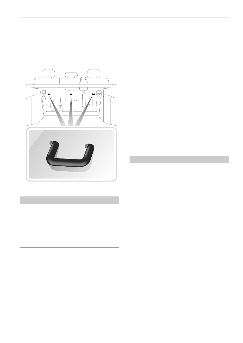
TETHER STRAP ANCHORAGES
Provision is made for the fitting of up to three
child seats or restraint systems in the rear
seats, of the type that require tether strap
anchorage points.
H4240
WARNING
Child restraint anchorages are designed to
withstand only those loads imposed by
correctly fitted child restraints. Under no
circumstances should they be used for adult
rear seat belts or for harnesses for attaching
other items or equipment to the vehicle.
There are three tether strap anchorage points.
These should be used to attach tether straps
from child seats or restraint systems. All three
anchorage points are fitted to the back of the
rear seat (shown in the accompanying
illustration).
Attaching tether straps
1. Install the child restraint securely in one of
the rear seating positions.
2. Pass the tether strap over the back of the
vehicle seat and beneath the underside of
the head restraint.
3. Attach the clip on the head of the tether
strap to the tether anchor on the back of
the vehicle seat.
4. Tighten the tether strap according to the
manufacturer’s instructio ns to remove any
slack in the webbing.
WARNING
• Always follow the child seat or restraint
system manufacturer’s instructions when
fitting tether straps.
• When fitting a child seat or restraint
system, always pass the tether strap over
the top of the seat back and beneath the
underside of the head restraint.
• If a child seat or restraint system is to be
fitted to the center seating position, the
center armrest must be in the stowed
position (folded into the seat).
47

Child Restraints
‘LATCH’ TYPE CHILD RESTRAINTS
H4322
‘LATCH’ (Lower Anchors and Tether for
Children)
The ‘LATCH’ three-point type child restraint
system complies with Federal Motor Vehicle
Safety Standards and is approved for fitting in
your vehicle.
Fitting the restraints
This type of child restraint system should only
be fitted in the two outer seating positions of
the second row seats. Anchor bars built into the
rear seat frame enable ‘LATCH’ type restraints
to be securely attached to the vehicle seat in
these positions only. The anchor bar locations
are shown in the illustration above.
Pass the tether strap over the top of the seat
back and beneath the underside of the head
restraint. Attach the clip on the head of the
tether strap to the appropriate tether anchor
and tighten the tether strap.
WARNING
If the restraint is not correctly anchored, there
is a significant risk of injury to the child, in the
event of a collision or emergency braking.
DO NOT attempt to fit ‘LATCH’ type restraints
to the center seating position - the anchor
bars are designed to hold restraints in the
outer seating positions only.
When fitting this type of child restraint, always
follow the instructions supplied by the
manufacturer of the restraint.
Once the restraint is installed, test the security
of the installation before seating the child.
Attempt to twist the restraint from side to side,
and to pull the restraint away from the vehicle
seat, then check that the anchors are still
securely in place.
48

Airbag SRS
Airbag SRS
AIRBAG SUPPLEMENTAL RESTRAINT SYSTEM (SRS)
H3362
The airbag supplemental restraint system
(SRS) provides additional protection for the
driver and front seat passenger, in the event of
a severe frontal impact on the vehicle.
WARNING
Always remember; the SRS/airbags are a
supplemental restraint system providing
ADDITIONAL protection in certain types of
frontal impact collisions only - they DO NOT
replace the need to wear a seat belt. To
reduce the risk of severe injury or death in the
event of a crash, all occupants in all seating
positions including the driver, should always
wear their seat belt whether or not an airbag
is present in that seating position!
Provided the front seat occupants are correctly
seated, with seat belts properly worn, the
airbags will provide additional protection to the
chest and facial areas in the event of the vehicle
receiving a severe frontal impact.
NOTE: Inflation and deflation of the airbags
takes place very quickly and will not protect
against the effects of secondary impacts that
can occur during multiple vehicle collisions.
The airbags are located in the center pad of the
steering wheel and the facia panel above the
glovebox.
49

Airbag SRS
WARNING
Following inflation, some SRS/airbag
components are hot - DO NOT touch until they
have cooled.
Even with SRS/airbag equipment fitted, seat
belts must ALWAYS be worn because:
• An airbag will only provide additional
protection in certain types of frontal
collisions. NO protection is afforded
against the effects of side or rear impacts,
rollover accidents, or minor frontal
impacts.
• Inflation and deflation take place
instantaneously and will not provide
protection against the effects of secondary
impacts that can occur during multiple
vehicle collisions.
WARNING
The airbag module inflates with considerable
speed and force. For your safety:
An inflating airbag can cause facial abrasions
and other injuries. The injurious effects of
airbag inflation can be minimized, by
ensuring driver and passenger are seated
correctly, with the seat moved back as far as
is practical, and the seat belts worn correctly.
National Highway Traffic Safety
Administration (NHTSA) recommends a
minimum distance of 10 inches (25 cm)
between the occupant’s chest and the driver’s
airbag module.
NEVER attach accessory items to an airbag
module cover, or place items of hand luggage
or any objects on the top of a module cover.
These could interfere with the inflation of the
airbag, or if the airbag inflates, be propelled
inside the vehicle causing injury or death to
the occupants.
DO NOT allow occupants to obstruct the
operation of the airbag modules by placing
their feet, knees or any part of their person in
contact with, or close to, an airbag module
whilst the vehicle is moving.
When an airbag inflates, a fine powder is
released. This is not an indication of a
malfunction. However, the powder may cause
irritation to the skin and should be thoroughly
flushed from the eyes and any cuts or
abrasions of the skin.
Both front seating positions are equipped with
knee bolsters to provide knee protection in
the event of an impact. DO NOT modify the
bolsters, or mount after-market equipment on
or behind them.
50

Airbag SRS
Seating positions
In order to provide optimum protection in the
event of a severe frontal impact, it is necessary
for the airbags to deploy with considerable
speed.
An inflating airbag can cause facial abrasions
and other injuries if the occupant is too close to
the airbag at the time of its deployment.
WARNING
To reduce the risk of accidental injury from
inflating airbags, seat belts should be
correctly worn at all times. In addition, both
driver and front seat passenger should adjust
their seat to provide the maximum practical
distance from the front airbags.
Occupants not seated correctly in allocated
seats can be subject to serious injury or death
upon airbag deployment.
Never place your arm over an air bag module
as a deploying air bag can result in serious
arm fractures or other injuries.
HOW THE AIRBAG SRS WORKS
In the event of a severe frontal impact, the
airbag control unit monitors the rate of
deceleration induced by the collision, to
determine whether the airbags should be
deployed.
Operation of the airbag SRS is dependent
entirely on the rate at which the vehicle's
passenger compartment changes speed as a
result of a collision. The circumstances
affecting different collisions (vehicle speed,
angle of impact, type and size of object hit, for
example), vary considerably and will affect the
rate of deceleration accordingly.
NOTE: The SRS/airbag is not designed to
activate in all frontal impacts; most minor
frontal impacts, heavy braking and driving over
pot holes will not result in sufficient
deceleration to cause the airbags to inflate. This
does not indicate that there is a fault with the
system. However, if as a result of an impact,
you believe the airbags should have deployed
and they failed to do so, please call
1(800)637-6837 for advice, or to arrange for a
Land Rover representative to inspect the
vehicle to determine whether the system
operated correctly.
It follows, therefore, that significant superficial
damage can occur without the airbags
deploying or, conversely, that a relatively small
amount of structural damage may cause the
airbags to be deployed.
Airbags will only deploy when they are
required to supplement the restraining force
of the seat belts.
In the case of a severe frontal collision, both
front airbags and seat belt pre-tensioners will
be deployed.
51

Airbag SRS
H3307
Airbag inflation is virtually instantaneous and
occurs with considerable force, accompanied
by a loud noise. The inflated bag, together with
the seat belt restraint system, limit the
movement of a front seat occupant, thereby
reducing the risk of injury to the head and upper
torso.
When an airbag inflates, a fine powder is
released. This is not an indication of a
malfunction, however, the powder may cause
irritation to the skin and should be thoroughly
flushed from the eyes and any cuts or abrasions
of the skin. After inflation the airbags deflate
immediately. This provides a gradual
cushioning effect for the occupant and also
ensures that the driver's forward vision is not
impaired.
WARNING
After inflation, some airbag components are
hot - DO NOT touch until they have cooled.
Airbag SRS warning light
Whenever the starter switch is turned to
position ‘II’, the diagnostic control unit
monitors the readiness of the system's
electrical circuits. The elements of the system
being monitored include:
• SRS warning light
• Rotary coupler
• Airbag modules
• Airbag diagnostic control unit
• Airbag wiring harness
WARNING
A warning light mounted on the instrument
panel will alert you to any malfunction of the
SRS/airbag. The system should always be
checked by a retailer if any of the following
symptoms occurs. These indicate a fault,
which may result in the SRS/airbag not
operating as required in the event of a frontal
impact.
• The warning light fails to illuminate when
the starter switch is turned to position ‘II’.
• The warning light fails to extinguish within
approximately five seconds after the
starter switch is turned to position ‘II’.
• The warning light illuminates after the
engine is started, or while the vehicle is
being driven.
52

Airbag SRS
CHILD SEATS
Children aged 12 years and under are more
likely than adult occupants to receive injuries
from inflating airbags. For this reason, it is
recommended that children should always be
seated in the second row of seats in a child
safety seat or restraint system appropriate to
their age and size, (see ‘CHILD RESTRAINTS
FOR SMALL CHILDREN AND BABIES’, page 45,
and ‘CHILD RESTRAINTS FOR LARGER
CHILDREN’, page 45).
If it is necessary for a child to travel in the front,
set the seat fully rearwards and use a front
facing child seat ONLY.
WARNING
DO NOT USE A REAR FACING CHILD SEAT IN
ANY FRONT PASSENGER SEAT LOCATION. If
the passenger airbag inflates, a child in a rear
facing child restraint could sustain serious
injury or death.
Children could be endangered in a crash if
their child restraints are not properly secured
in the vehicle. Be sure to install child
restraints according to the manufacturer's
instructions.
Under no circumstances should a rear facing
child seat be installed facing forward in any
seating position.
SERVICE INFORMATION
WARNING
DO NOT attempt to service, repair, replace,
modify or tamper with any part of the airbag
SRS, or wiring in the vicinity of an airbag SRS
component; this could cause the system to
activate, resulting in personal injury.
Some SRS/airbag and seat belt pre-tensioner
components must be replaced by a Land Rover
retailer after 10 or 15 years respectively from
the date of manufacture (shown on the
certification plate on the rear face of the left
hand front door). See your Passport to Service
for details of the dates.
In addition, ALWAYS contact your retailer if:
• an airbag inflates.
• the front of the vehicle is damaged, even if
the airbag has not inflated.
• any part of an airbag module cover (the
steering wheel center pad or facia panel)
shows signs of cracking or damage.
53

Airbag SRS
WARNING
The components that make up the airbag SRS
are sensitive to electrical or physical
interference, either of which could easily
damage the system and cause inadvertent
operation or a malfunction of the airbag.
For your safety it is recommended that you
seek the assistance of a Land Rover retailer to
carry out any of the following:
• Removal or repair of any wiring or
component in the vicinity of any of the SRS
components, including the steering
wheel, steering column, instrument and
facia panels.
• Installation of electronic equipment such
as a mobile phone, two-way radio or
in-car entertainment system.
• Attachment of accessories to the front of
the vehicle.
WARNING
Modification of the front of the vehicle could
adversely affect airbag performance and
should NOT be undertaken.
Disposing of vehicles
If you sell your vehicle, be sure to inform the
new owner that the vehicle has an airbag SRS
and make the new owner aware that certain
components of the system will need replacing
after a number of years. These intervals are
detailed in your Passport to Service.
If your vehicle is to be scrapped; uninflated
airbags are potentially very dangerous and
must be safely deployed in a controlled
environment by qualified personnel, before a
vehicle is scrapped.
54

Steering Column
Steering Column
STEERING COLUMN ADJUSTMENT
H2300
The angle of the steering column can be
adjusted to suit your driving position:
1. With the vehicle stationary, push the
locking lever fully down to free the
steering column.
2. Move the steering wheel (up or down) into
the desired position, making sure the
instrument panel is clearly visible.
3. When adjustment is complete, pull the
locking lever fully up to lock the steering
column in position.
WARNING
DO NOT adjust the steering column while the
vehicle is in motion. This is extremely
dangerous and may result in loss of control of
the vehicle!
DO NOT drive the vehicle unless the locking
lever is in the locked position (fully up).
55

Instruments
INSTRUMENT PANEL
Instruments
4
5
6
2
3
r/ mi n x 1000
1
0
H4236
1. Fuel gauge
The pointer indicates the fuel level when the
starter switch is turned to position ‘II’. After
refuelling, the pointer slowly rises to the new
level after the starter switch is turned on. When
the starter switch is turned off, the pointer
quickly lowers to the ‘empty’ position.
An indicator light in the fuel gauge illuminates
when the fuel level is low (approximately 1.8 US
gallons (7 liters) fuel remaining). If the light
illuminates, refuel at the earliest opportunity.
An arrow on the face of the gauge indicates on
which side of the vehicle the filler is located.
CAUTION: Never allow the vehicle to run out of
fuel - the resultant misfire could damage the
catalytic converter.
NOTE: Driving on twisting or hilly roads may
disturb the accuracy of the fuel gauge. It is
advisable to check the fuel level when the
vehicle is travelling on a straight, level road.
2. Tachometer
Indicates engine speed in revolutions per
minute (x 1000). To protect the engine from
damage, NEVER allow the tachometer pointer
to enter the RED sector.
70
90
120
0
50
0
1
MPH km/h
140
160
110
180
200
130
220
80
0
6
7
8
30
10
40
20
3. Speedometer
Indicates road speed in miles per hour and
kilometres per hour.
NOTE: Prominence is given to the speed units
used in the country in which the vehicle will be
used.
4.Trip recorder reset button
When the starter switch is turned on, the
display shows either the odometer reading, or
the trip recorder reading. By pressing the trip
recorder reset button briefly, the display will
change between trip recorder and odometer
modes.
With the trip recorder mode displayed, press
and hold the reset button for 2 seconds to reset
the trip recorder display to zero.
5. Temperature gauge
This gauge indicates the temperature of the
engine coolant. As the engine warms up, the
pointer will rise to the mid-point of the gauge,
where it should remain while the engine is
operating at its normal temperature.
54321
56

Instruments
If the pointer reaches the RED mark, the coolant
is too hot and severe engine damage could
result; in which case you should stop the
vehicle as soon as safety permits and seek
qualified assistance.
6. Digital display
H3370
The panel displays the following:
• Odometer reading (shows the total distance
travelled by the vehicle). The word ‘ODO’ is
displayed.
• Trip recorder (for recording individual
journey distances). The word ‘TRIP’ is
displayed instead of ‘ODO’.
• Gear selector position (‘1’, ‘2’, ‘4’, ‘P’, ‘R’,
‘N’, ‘D’).
• The word ‘SPORT’ confirms the selection of
Sport mode.
• Manual mode gear selection information
(‘1’, ‘2’, ‘3’, ‘4’ or ‘5’).
For further information concerning the
automatic transmission, (see
‘‘CommandShift
page 103’).
TM
TRANSMISSION’,
57
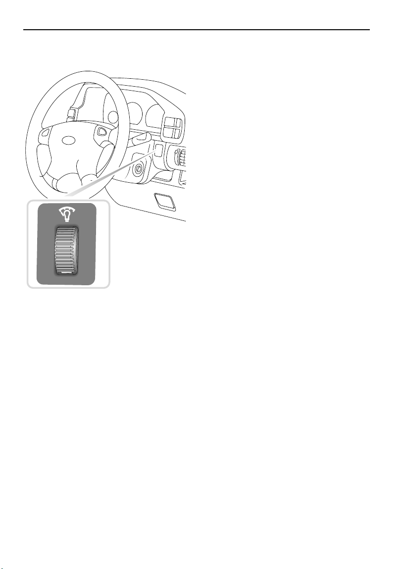
Instrument illumination control
H4019
Instruments
Rotate the control up to increase, or down to
reduce, the intensity of instrument panel
illumination.
The instrument illumination control also
adjusts illumination of all switch lighting
sources forward of the driver.
58

Warning Lights
INSTRUMENT PANEL
Warning Lights
4
r/mh x 1000
5
6
3
2
1
0
H4775
IMPORTANT INFORMATION
RED warning lights are of particular
importance, their illumination indicates
that a fault exists. If a RED warning light
illuminates, stop the vehicle and review
the specific instructions given in this
section.
Direction indicators - GREEN
The left or right warning light
flashes in time with the relevant
direction indicator when they are
operated. If either warning light fails to flash or
flashes rapidly, the selected direction indicator
light is not operating.
NOTE: If the hazard warning lights are
operated, both direction indicator warning
lights will flash together.
Headlight high beam - BLUE
Illuminates when the headlights are
switched to high beam.
70
90
120
0
50
0
1
MPH km/h
140
160
110
180
200
130
220
80
0
6
7
8
30
10
40
20
Cruise control - AMBER
Illuminates when the cruise control
master switch is turned on and
cruise control is active, and
extinguishes when the switch is turned off or if
cruise control is deactivated.
Service engine soon- AMBER
Illuminates as a bulb check when
the starter switch is turned to
position ‘II’ and extinguishes when
the engine is started. If the light illuminates
while the engine is running, this indicates the
detection of an emissions fault by the engine
management system.
If the light illuminates and the vehicle drives
normally:
• Contact a retailer to arrange a service
appointment at your earliest convenience you may still drive the vehicle.
If the light flashes and/or the vehicle does not
drive normally:
• Avoid high speeds and seek immediate
assistance from your retailer.
59
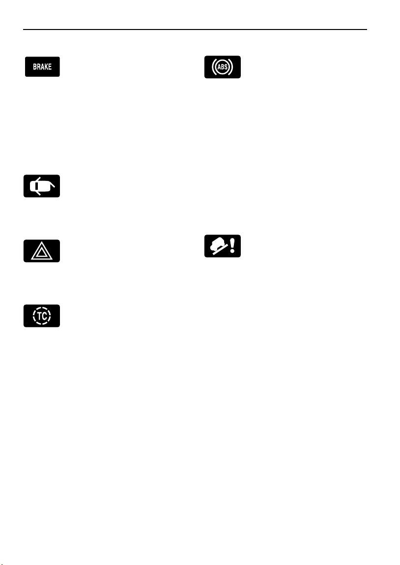
Warning Lights
Parking brake & brake system - RED
The light illuminates when the
parking brake is applied and
extinguishes when it is fully
released. If the light continues to illuminate
after the handbrake is released, a fault with the
braking system is indicated; check the brake
fluid level (see ‘BRAKE FLUID’, page 160). If the
light continues to illuminate after this, seek
qualified assistance urgently.
Door open - RED
Illuminates when any of the doors
(including the taildoor and hood)
are not fully closed. DO NOT drive
the vehicle with the light illuminated.
Hazard warning lights - RED
Illuminates in conjunction with the
direction indicator warning lights,
when the hazard warning lights are
operating.
Traction control - AMBER
Illuminates as a bulb and system
check when the starter switch is
turned to position ‘II’ and
extinguishes after 4 seconds approx. The light
illuminates for a minimum of 2 seconds, when
traction control is operating.
If the light illuminates continuously while
traction control is NOT operating, a fault with
the system is indicated; seek qualified
assistance.
The light also has an overheat function: if
traction control is required, but the brakes are
too hot, the light will flash for the period when
traction control is required and traction has
been lost.
ABS - AMBER
Illuminates for approximately
1 second as a bulb and system
check when the starter switch is
turned to position ‘II’, and then extinguishes. If
the light does not extinguish, a fault has
occured with the ABS system and you should
consult your Land Rover retailer at the earliest
opportunity.
If the light remains on or subsequently
illuminates while driving, a fault has been
detected by the self-monitoring system. This
means that full ABS control may not be
available and you should consult your retailer at
the earliest opportunity.
Hill descent control (HDC) ‘failure’ - AMBER
The light illuminates briefly as a
bulb check when the starter switch
is turned to position ‘II’. The light
will flash if the brakes become in danger of
overheating and continue flashing until the
brakes have cooled sufficiently to enable HDC
to operate again (see also ‘HDC fade-out’,
page 109).
If the light illuminates at any other time, a fault
in the system is indicated. If this occurs,
deselect HDC and consult your Land Rover
retailer.
60

Warning Lights
Hill descent control (HDC) ‘information’ GREEN
Illuminates briefly as a bulb check
when the starter switch is turned to
position ‘II’ and will illuminate
when HDC is selected.
If HDC is selected when either of the operating
gears is engaged (1st or reverse), the light will
illuminate continuously.
When HDC is selected and a non-operating gear
position is engaged, the light will flash to inform
the driver that HDC is selected, but not
operating (see also ‘HDC fade-out’, page 109).
Low oil pressure - RED
Illuminates as a bulb check when
the starter switch is turned to
position ‘II’ and extinguishes when
the engine is started. If the light remains on,
flashes on and off or illuminates continuously
when driving, serious engine damage could
occur; stop the vehicle as soon as safety
permits and SWITCH OFF THE ENGINE
IMMEDIATELY. Seek qualified assistance
before driving.
Service engine - AMBER
Illuminates briefly when the
starter switch is turned to position
‘II’. If it remains on, or illuminates
at any other time, the engine management
system requires attention. Stop the vehicle as
soon as safety permits and switch off the
engine for at least 30 seconds; if the light
illuminates again after the engine is restarted, it
is permissible to continue driving (with reduced
engine power), but qualified assistance must be
sought as soon as possible, to prevent potential
engine damage.
Battery charging - RED
The light illuminates as a bulb
check when the starter switch is
turned to position ‘II’ and
extinguishes as soon as the engine is running.
If it remains on, or illuminates when driving, a
fault with the battery charging system is
indicated. Seek qualified assistance urgently.
Seat belt - RED
ensure that all occupied seat belts are securely
fastened. The light extinguishes after
approximately five seconds, or when the
driver’s seat belt is fastened.
Airbag SRS - RED
seconds. If the light illuminates at any other
time, seek qualified assistance urgently.
*
The light illuminates when the
starter switch is turned to position
‘II’ as a reminder to the driver to
The light illuminates when the
starter switch is turned to position
‘II’ and extinguishes after about five
61

Audible Warnings
Audible Warnings
AUDIBLE WARNINGS
Lights on reminder
If the lights are left on after the starter switch is
turned off, a warning chime will sound when the
driver's door is opened. The chime will cease as
soon as the lights are switched off or when the
driver's door is closed.
Starter key reminder
If the key is left in the starter switch while the
driver's door is open, a warning will chime
continuously. The chime stops as soon as the
door is closed, or the key is removed from the
starter switch.
62

Lights & Indicators
Lights & Indicators
DIRECTION INDICATORS
H3340
Move the lever DOWN to indicate a LEFT turn,
and UP to indicate a RIGHT turn (the
appropriate GREEN warning light on the
instrument panel will flash in time with the
direction indicators).
Hold the lever part-way up or down against
spring pressure to indicate a lane change.
LIGHTS
2
1
H3341
The side, tail and headlights operate with the
starter switch in any position.
If the exterior lights are left on after the starter
switch is turned off, a warning chime will sound
as soon as the driver's door is opened. The
chime will cease as soon as the lights are
switched off, or the door is closed.
Side, tail and instrument panel lights
Turn lighting switch to position 1.
Headlights
Turn lighting switch to position 2.
63

Lights & Indicators
Headlight high and dipped beams
H3342
Pull the lever fully towards the steering wheel to
change headlight beams (BLUE warning light
glows when the headlights are on high beam).
To flash the headlights, pull the lever part way
towards the steering wheel and release.
HAZARD WARNING LIGHTS
H3344
Press to operate; all the direction
indicator lights (including those
fitted to a trailer) will flash
together. Use ONLY in an emergency to warn
other road users when your stationary vehicle
is causing an obstruction, or is in a hazardous
situation. Remember to switch off before
moving away.
64

Wipers & Washers
Wipers & Washers
OPERATING
The wipers and washers will only operate when
the starter switch is turned to position ‘I’ or ‘II’.
IMPORTANT
• DO NOT operate the wipers on a dry
windshield.
• To prevent possible overload damage to
the wiper motor, in freezing or very hot
conditions ensure that the blades are
not frozen or stuck to the glass before
operating the wipers.
• In winter, remove any snow or ice from
around the arms and blades, including
the wiped area of the windshield and
the heater air intakes.
WINDSHIELD WIPERS
3
2
1
H3345
NOTE: If the wiper blades have stuck to the
glass, a thermal cut-out may temporarily
prevent the wiper motor from operating. If this
is the case, switch the wipers off, free the
blades from the obstruction and then switch on
again.
Intermittent wipe
Turn switch to position 1.
Normal speed wipe
Turn switch to position 2.
Fast speed wipe
Turn switch to position 3.
NOTE: If the front windshield wipers are
operating (in either intermittent or continuous
mode), the rear wiper operates automatically
whenever reverse gear is selected.
65

Wipers & Washers
Single wipe
H3520
Pull the lever down and release immediately.
NOTE: With the lever held down, the wipers will
operate at high speed until the lever is released.
Variable delay (intermittent wipe)
WINDSHIELD WASHERS
H3347
Pull the lever toward the steering wheel. The
windshield wipers will operate in conjunction
with the washers for as long as the lever is held
in this position, the wipers continuing for a
further 3 to 4 wipes after the lever is released.
WARNING
If you operate your vehicle in temperatures
below 40 degrees F, use washer fluid with
anti-freeze protection. In cold weather,
failure to use washer fluid with anti-freeze
protection could result in impaired
windshield vision and increase the risk of a
vehicle crash.
H3346
Rotate the inner switch to vary the delay
between wipes.
NOTE: State or local regulations may restrict
the use of volatile organic compounds (VOC’s),
which are commonly used as anti-freeze agents
in washer fluid. A washer fluid with limited VOC
content should be used only if it provides
adequate freeze resistance for all regions and
climates in which the vehicle will be operated.
For more information on Wipers and Washers,
see ‘WINDSCREEN WASHER TOP-UP’,
page 181 & ‘HEADLIGHT WASHERS’, page 181
66

Wipers & Washers
REAR WINDSHIELD WIPER AND
WASHER
Rear windshield wash/wipe
H3510
Press and hold the switch for the
required duration of windshield
washing. The wiper operates
automatically during washing and continues for
a further 4 wipes (approx.) after the switch is
released.
Rear windshield wiper
H3508
Press to operate: after
continuously wiping 3 or 4 times,
the wiper operates intermittently
(approx. once every 6 seconds) until switched
off.
NOTE: When reverse gear is selected, the rear
wiper will operate continuously in tandem with
the front wipers.
NOTE: Opening the taildoor, or lowering the
rear windshield, will switch the rear wiper off.
67

Horn
HORN
H3349
To operate, press either of the horn switches
set into the steering wheel pad.
Horn
68

Mirrors
Mirrors
EXTERIOR MIRRORS
NOTE: The right hand mirror glass is convex,
providing a wider field of vision. As a result,
objects reflected in this mirror are closer than
they appear.
Adjustment
H3363
Folding the mirror body
The body of each door mirror is designed to
fold forwards or rearwards on impact. They can
also be folded back manually towards the side
windows into a ‘park’ position, to enable the
vehicle to negotiate narrow openings.
• Turn the control to the ‘L’ or ‘R’ position to
select either the left or right hand mirror.
• With the starter switch turned to position
‘II’, push the control in the appropriate
direction to tilt the mirror glass up/down/left
or right.
• When adjustment is complete, return the
control to the OFF position (midway
between ‘L’ and ‘R’).
Heating elements
The exterior mirrors have integral heating
elements for dispersing ice and mist, which
operate automatically whenever the starter
switch is in position ‘II’.
69

Mirrors
INTERIOR MIRROR
H2319
The interior mirror can be dipped to reduce
glare from following vehicles. In the event of
excessive glare, move the lever at the base of
the mirror forward to ‘dip’ the mirror. Normal
visibility is restored by pulling the lever back to
its original position.
NOTE: In some circumstances, the view
reflected in a ‘dipped’ mirror can confuse the
driver as to the precise position of following
vehicles. Remember to take additional care!
VANITY MIRROR*
H3335
To use the vanity mirror, pull down the
passenger's sun visor. On some models, the
vanity mirror is illuminated; lift the cover to
illuminate the mirror.
NOTE: Always close the cover, or on vanity
mirrors not fitted with a cover, always return
the visor to its stowed position when not in use,
to avoid possible scorching of the seats by the
sun reflected in the mirror.
70

Windows
Windows
ELECTRIC WINDOW CONTROLS
WARNING
Accidental closure of an electrically operated
window on fingers, hands or any vulnerable
part of the body, can result in serious
personal injury. Always observe the following
precautions:
• ENSURE that passengers are kept clear
while the windows are being operated and
that the windows are not obstructed when
opening or closing.
• ENSURE that all adult passengers are
familiar with the controls and the potential
dangers of operating electric windows.
• DO NOT allow passengers to extend any
part of their bodies through the windows
while the vehicle is moving.
• NEVER leave children alone in the vehicle
as this could result in injury or even death.
5
The switches on the center console operate the
windows as follows:
1. Right-hand rear window.
2. Left-hand rear window.
3. Left-hand front window.
4. Right-hand front window.
5. Isolation switch for rear door windows.
NOTE: Electric rear windows can also be
operated by the individual switches mounted on
each rear door, provided that the isolation
switch has not been activated.
Window operation
The electric windows can be operated when the
starter switch is at position ‘II’ and for up to 45
seconds after the starter switch is turned off
(provided neither front door is opened in the
meantime).
Press and hold the bottom half of a switch to
lower and the upper half to raise. The window
will stop moving when the switch is released.
ALWAYS close the windows when the vehicle is
unattended.
Rear window isolation switch
Press once to isolate the rear window switches
(indicator light in the switch illuminates); press
a second time to restore independent control.
H4331
3
2
4
ALWAYS isolate the rear window switches
1
when carrying children.
‘One touch’ down (Driver's door only)
By briefly pressing (and then releasing) the
bottom half of the switch, the window will open
fully at a single touch. Window movement can
be stopped at any time by briefly pressing the
upper half of the switch.
71
WARNING
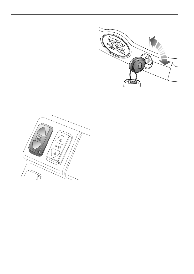
Windows
ELECTRIC TAILDOOR GLASS
NOTE: Long loads should be carried on the roof
rack. If it is necessary to carry a load that
protrudes through the taildoor window, the
weight of the load must NOT rest on the glass
of a partially open window. Damage to the glass
or window mechanism may occur (see also
‘Accommodating long loads’, page 38).
‘Accommodating long loads’, page 38
The taildoor glass can be lowered from outside
the vehicle, to enable easy access to the
loadspace area when it is impossible or
inconvenient to open the taildoor.
Raising and lowering
H3521
From outside the vehicle:
Press and hold the UNLOCK button on the
remote handset (hold for 2 seconds) - the
taildoor glass will fully lower.
To raise the glass, insert the key into the switch
mounted in the taildoor and turn clockwise. If
the switch is released before the glass is fully
raised it will automatically lower again.
NOTE: If the vehicle is locked when the glass is
lowered using the handset, the driver's door
will unlock and vehicle security will be disabled.
In this case, remember to relock the vehicle.
H3374
From inside the vehicle:
With the starter switch in position ‘II’, press and
hold the bottom half of the switch to lower the
glass. Movement will stop when the switch is
released.
Press the upper half of the switch to raise the
glass. If the switch is released before the glass
is fully raised it will automatically lower again.
One touch down:
By briefly pressing (and then releasing) the
bottom half of the switch, the taildoor glass will
open fully at a single touch.
Battery disconnection
If the battery has been disconnected, the
taildoor glass will need to be recalibrated. If the
alarm was armed when the battery was
disconnected (or discharged), disarm the
alarm after reconnection - the glass will fully
lower (this will happen automatically if the
alarm was in a disarmed state when the battery
was disconnected).
After battery reconnection, fully raise the glass
- the taildoor glass is now recalibrated (if the
glass is not fully raised, an error ‘beep’ will
sound).
72

Sunroof
Sunroof
ELECTRIC SUNROOF*
H3312
The sunroof can be operated when the starter
switch is turned to position ‘II’ and for up to 45
seconds after the starter switch is turned off
(provided neither front door is opened in the
meantime).
The roof opens in two separate phases as
follows:
• To tilt the roof: Press the bottom half of the
switch - the rear edge of the roof rises to the
tilted position.
• To open the roof: With the sunroof fully
tilted, press the bottom half of the switch the roof remains tilted and slides towards
the rear until fully open or the switch is
released.
To close the roof: press the upper half of the
switch - the sunroof will first close to the tilted
position, then it will return the tilted roof to the
fully closed position. The sunroof can be
stopped (at any position) by releasing the
switch.
WARNING
Accidental closure of a sunroof on fingers,
hands or any vulnerable part of the body, can
result in serious personal injury. Always
observe the following precautions:
• ENSURE that passengers are kept clear
when operating the sunroof and that the
sunroof is not obstructed when opening or
closing.
• ENSURE that all adult passengers are
familiar with the controls and the potential
dangers of operating an electrically
operated sunroof.
• DO NOT allow passengers to extend any
part of their bodies through the sunroof
aperture while the vehicle is moving.
• NEVER leave children alone in the vehicle
as this could result in injury or even death.
• Do not open the sunroof if the load on the
roof rack will impede its operation.
CAUTION: Do not operate the sunroof in
freezing conditions, or when the roof panel is
covered in ice or snow.
Sunroof visor
The sunroof visor must be opened and closed
manually.
73

Targa Roof
Targa Roof
TARGA ROOF
H3313
The targa roof is made up of twin glass or
composite panels set into the roof. Either or
both of which can be tilted open or removed.
Tilting a panel (see left inset)
1. Pull the handle forward to unlock.
2. Push the handle up.
3. Push the handle to the rear until it ‘clicks’
into the lock position.
WARNING
DO NOT allow passengers to extend any part
of their bodies through roof apertures while
the vehicle is moving - injury from flying
debris, branches of trees or other
obstructions could occur.
Storing the panels
To close the panel, reverse the above
procedure.
Removing a panel
WARNING
DO NOT attempt to remove the targa roof
panels when the vehicle is moving!
Half tilt the panel (as in 1 and 2 above), then
press the red catch to detach the handle
linkage. From outside the vehicle, raise the rear
of the panel until the two front hinges
disengage and lift the panel off.
NOTE: Handle glass with care, avoid damage to
the surfaces, especially along the edges.
H3314
After removal, always protect the panels by
placing them sideways in the stowage case
attached to the rear seats in the luggage
compartment as shown.
WARNING
DO NOT drive with the roof panels loose in the
vehicle, they could become dangerous
projectiles in the event of an accident or
emergency maneuver.
74
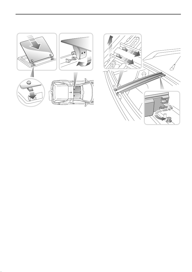
Targa Roof
Refitting a panel
H3315
Before refitting, note that the panels are not
interchangeable because the curvature at each
side of the roof is more pronounced than in the
center. To ensure accurate refitting, the one
rounded corner of the panel should be
positioned at the front OUTSIDE corner.
1. Locate the hinges over the top of and
through the slots in the wind deflector into
their appropriate slots at the front of the
roof.
2. Lower the roof and, ensuring that the
handle linkage is the correct way up, push
the handle rearwards as if to lock.
3. The handle should now be engaged -
ensure that the red button is fully
retracted, then attempt to open (tilt) the
roof to check.
Removing the ‘T-bar’
H3316
With both panels removed, the ‘T-bar’ can also
be removed:
• Press the RED catches rearwards (as
arrowed), then pull the bar upwards and
then forwards to remove.
NOTE: The ‘T-bar’ can be stowed in the pocket
provided in the stowage bag in the luggage
compartment (see ‘Storing the panels’,
page 74)
When replacing, ensure that the ‘T-bar’ is
secured at the rear, before pushing downwards
to engage the front (RED) locking catches.
NOTE: ALWAYS close and secure the roof when
the vehicle is to be left unattended.
75

Heating & Ventilation
VENTILATION
Heating & Ventilation
H2422
The ventilation system provides fresh or heated
air to the interior of the vehicle from the air
intake grille in front of the windshield.
NOTE: Always keep the air intake grille clear of
obstructions such as leaves, snow or ice.
Air outlets are provided to the windshield, face
and feet - the location of the vents is shown in
the illustration above. The temperature of the
air is controlled by the heater.
Information concerning the operation of the
heating and ventilation system, as well as the
air conditioning, appears on the pages that
follow.
76
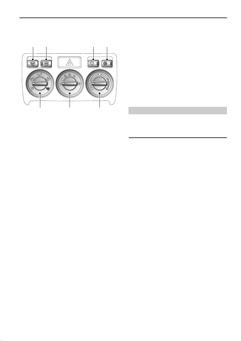
Heating & Ventilation
HEATER CONTROLS
214
3
765
H3317A
1. Heated front windshield
Press to operate; the indicator light in the
switch illuminates whenever the heater is on
and extinguishes when the heater is turned off.
NOTE: The front windshield heater will operate
only when the engine is running and will switch
off automatically after approximately 10
minutes.
2. Rear windshield demister
Press to operate; the indicator light in the
switch illuminates whenever the demister is on
and extinguishes when the demister is turned
off.
NOTE: The rear windshield demister will
operate only with the taildoor fully closed and
when the engine is running and will switch off
automatically after approximately 15 minutes.
NOTE: DO NOT stick labels over the heating
elements, and DO NOT scrape or use abrasive
materials to clean the inside of the window.
3. Air recirculation button
Press to recirculate air inside the vehicle
(indicator light illuminates).
The air recirculation mode prevents the heating
system from taking in fresh air from outside the
vehicle. Instead, the air already inside the
vehicle is recirculated, thus preventing the
entry of traffic fumes. In cold weather air
recirculation also enables warmer air to be used
to defrost the windshield when the engine is
still cold.
WARNING
The air recirculation mode can cause the
windshield to mist. If this happens, switch off
air recirculation immediately.
4. Air conditioning
With the engine running, press to operate. The
indicator light in the switch illuminates when
the air conditioning is switched on.
5. Air temperature control
Rotate the control clockwise (towards the RED
segments) to increase the air temperature, or
anti-clockwise (towards the BLUE) to reduce
the temperature.
6. Air blower control
Turn the control clockwise to progressively
increase the blower speed.
NOTE: With the control in position ‘O’, the
volume of air entering the vehicle is dependent
on driving speed alone.
77

Heating & Ventilation
7. Air distribution control
Rotate to select air distribution:
Air to face vents
(to ensure best performance, the face
level vents must be fully open)
Air to face vents and foot outlets
(to ensure best performance, the face
level vents must be fully open)
Air to foot outlets
Air to foot outlets and windshield
(if the ambient temperature is
approximately 41º F (5º C) or higher, the
air conditioning will automatically dehumidify
the air to reduce misting).
All air to windshield
(if the ambient temperature is
approximately 41º F (5º C) or higher, the
air conditioning will automatically dehumidify
the air to reduce misting).
USING YOUR HEATER
Fresh air enters the heater unit through the
grille in front of the windshield and stale air is
drawn out through vents in the rear of the
vehicle. Ducts beneath the front seats provide
heating for rear seat passengers - these must
not be obstructed.
The following examples of basic heater settings
are intended as a general guide; the air
distribution, temperature and blower controls
can then be further adjusted to suit your
comfort requirements.
Always remember that full heating is not
available until the engine has reached its
normal operating temperature.
Maximum heating
H3318A
Set the controls as shown, with the blower at
the slowest speed (position 1) until the
temperature gauge indicates that the engine is
warming up - the blower speed can then be
increased.
Demisting
H3319A
Set the controls as shown, to obtain the
maximum flow of heated air from the
windshield and side window vents.
Opening a window may improve ventilation.
78
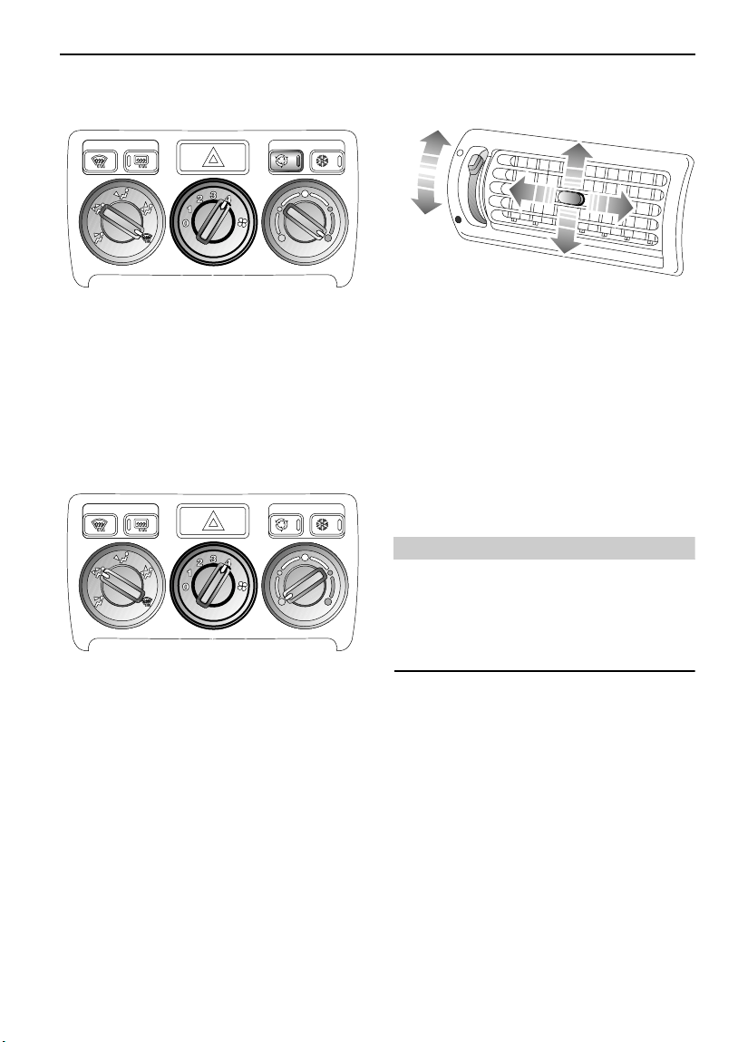
Heating & Ventilation
Defrosting
H3320A
Set the controls as shown and switch on air
recirculation to prevent cold air from being
drawn into the vehicle. Turn air recirculation off
as soon as the windshield is clear, to prevent
any possibility of the windshield misting.
Maximum ventilation
H3321A
FACE LEVEL VENTS
H2329A
Rotate the thumbwheel down to open or up to
close the vents. Direct the air flow by moving
the control in the center of the louvres up or
down, or from side to side.
To increase output from the center face vents,
shut the outer vents.
When carrying rear seat passengers, use the
outer vents for the front seat occupants and use
the more powerful center vents for the rear seat
passengers.
WARNING
Driving with the taildoor or taildoor window
open is not recommended because poisonous
exhaust fumes will be drawn into the vehicle
(see ‘Accommodating long loads’, page 38
for advice).
Set the controls as shown, with the face level
vents open.
Adjust the blower speed as required.
79

Heating & Ventilation
AIR CONDITIONING
The air conditioner provides additional cooling
and also reduces humidity. This can be used to
demist windows quickly in damp weather and,
when used in conjunction with the heater,
makes the interior of the vehicle warm and dry.
NOTE: In high humidity conditions, slight
windshield misting may be experienced when
the air conditioning is turned on. This is a
natural occurrence for most automotive air
conditioning systems; it is not a fault with the
system and will clear after a few seconds, once
the air conditioning is operating.
Using the air conditioning
The air conditioning can only be used when the
engine is running. For the air conditioning
system to operate efficiently, all windows (and
the sunroof) should be closed, and the air
intake vents free from ice, snow, leaves and
other debris.
With the engine running, press the ‘A/C’ button,
and adjust the air distribution, air temperature
and blower controls as required.
NOTE: The air conditioner will only operate
when the blower is switched on.
Operation of the air conditioning system places
an extra load on the engine. In very hot
conditions or when the engine is required to
work unusually hard (climbing long hills or
driving in congested traffic, for example), this
could result in high engine temperatures. If the
pointer nears the RED zone of the temperature
gauge, temporarily turn the air conditioning off
until engine temperatures return to normal.
NOTE: Under extreme conditions, the air
conditioning may automatically switch off, to
prevent damage to the engine.
Rapid cooling:
With the engine running press the ‘A/C’ button,
turn the air temperature control to the BLUE
segment, select air recirculation and turn the
blower switch to 4. Turn off air recirculation and
adjust the blower when the vehicle interior is
cool.
NOTE: In very hot conditions, it may be
advisable to fully ventilate the vehicle by
opening the windows and sunroof for a while
before closing them again and operating the air
conditioning.
Maintaining the air conditioning
The air conditioning system is sealed and major
maintenance should only be carried out by a
qualified technician. To maintain the system in
peak condition, owners should ensure that the
system is operated for a short period every
week (even during the cold winter months);
with the engine at its normal operating
temperature, run the air conditioning for at least
ten minutes whilst driving at a steady speed.
Surplus water produced by the dehumidifying
process is expelled from the system via drain
tubes beneath the vehicle. This may result in a
small pool of water forming on the road when
the vehicle is stationary and is not a cause for
concern.
80

Heating & Ventilation
HEATED FRONT SEATS*
H3494
With the starter switch turned on and the
engine running, press the switches to operate
the heating elements in either the driver's or
front passenger seat (the indicator light in the
switch illuminates). Press a second time to
switch off.
NOTE: The seat heaters will switch off
automatically 15 seconds after the starter
switch is turned off.
The seat heaters are thermostatically controlled
and operate intermittently to achieve and then
maintain a predetermined temperature between
79° F and 97° F (26° C and 36° C).
NOTE: Owners should be aware that the seat
heaters consume considerable power from the
battery and for this reason, it is recommended
that they are operated only with the engine
running.
81

Interior Equipment
Interior Equipment
COURTESY & MAP READING LIGHTS
H2352A
Front courtesy and map reading lights
H2593
Rear courtesy light
Press the appropriate switch to illuminate (or
extinguish) the lights manually.
The front and rear lights illuminate
automatically when the vehicle is unlocked or
whenever a door or taildoor is opened, and
extinguish approximately 15 seconds after ALL
the doors are closed, or as soon as the starter
switch is turned on.
If a door or the taildoor remains open for ten
minutes or more, a ‘time out’ function will
extinguish the courtesy lights in order to
prevent the battery from discharging.
LUGGAGE COMPARTMENT LIGHT
Illuminates automatically when the taildoor is
opened.
CLOCK
H
M
H4326
The digital clock display illuminates when the
starter switch is turned on and dims for night
viewing when the sidelights are switched on.
With the starter switch turned to position ‘I’,
depress the hour (‘H’) and minute (‘M’) buttons
to set the time. If both buttons are pressed
together, the display will change between 24
hour and 12 hour displays.
NOTE: If the battery is disconnected, the clock
will need to be reset.
NOTE: If the map reading lights or rear courtesy
light are left on after being manually selected,
they will NOT extinguish automatically.
The courtesy lights will extinguish when the
vehicle is locked.
82

Interior Equipment
GLOVEBOX
WARNING
DO NOT drive with the glovebox open. An
open glovebox could cause injury to the front
seat passenger in the event of a collision.
H3534
Lift the handle to open the glovebox.
The left hand compartment in the glovebox can
be used to store CD cases.
DRIVER'S STORAGE AREA
WARNING
DO NOT drive with the storage area open. The
storage area lid could cause serious injury in
the event of a collision.
H3365
Glovebox light
Operates automatically when the exterior lights
are switched on and the passenger glovebox is
opened.
Lift the handle to open the driver's storage area
- only when the vehicle is stationary.
The left hand compartment in the storage area
can be used to store tape and CD cases.
83

Interior Equipment
PASSENGERS’ STORAGE
Rear seat passengers can store items in the
pockets in the rear of the front seats and in
overhead nets provided in 5-door vehicles.
WARNING
Do not use the overhead nets to hold anything
other than light items such as maps or
sunglasses. Anything heavier than this could
be thrown about in the passenger
compartment and possibly injure occupants
in the event of an accident or emergency
maneuver
DRINKS STOWAGE
H3325A
The expanding strap fitted to the front door
stowage compartments can be used to store
drink containers securely when driving.
NOTE: Drink containers over 0.5 liter capacity
will not be properly secured by the strap.
WARNING
Do not use the strap to store hot drinks.
84

Interior Equipment
CUP HOLDERS
WARNING
The driver should not drink and should not use
the cup holder while driving.
Retractable cup holders sho uld be kept closed
when not in use.
DO NOT place anything other than suitable
drink containers in the cup holders, because
such items may be thrown about in the
passenger compartment and possibly injure
occupants in the event of an accident or
emergency maneuver.
DO NOT carry open-top drink containers in the
cup holders while the vehicle is in motion; a
spilled hot drink could cause personal injury.
Spilled drinks can also damage upholstery,
carpeting and electrical components.
Use only for soft containers. DO NOT use to
hold cups made of glass, china or hard
plastic, as these may caus e injury in the event
of an accident or emergency maneuver.
Unopened sealed containers (drinks cans, for
example) are hard objects and may also
cause injury.
Front cup holders
H3774
Press the button (arrowed) to open the cup
holder. Push the flap centrally to close. The
rubber mats inside the holder can be removed
for cleaning.
Rear cup holders
H2550
With the center armrest lowered, press the
front of the cup holder to open. The retaining
arms can be adjusted to suit a range of
container sizes. Press the front of the cup
holder again to close.
85

Interior Equipment
SUN VISOR
H2424
To shield your eyes from the sun, pull the visor
down from the roof; the visor can be used to
shield the upper part of the windshield or the
side window as required.
NOTE: On some models, the underside of the
sun visors are fitted with a vanity mirror with its
own illumination.
ASHTRAY
WARNING
DO NOT use the ashtray for disposing of waste
paper or other combustible items.
H3336
Front ashtray illustrated
Push to access the front or rear ashtray. To
remove for emptying; with the ashtray open,
carefully pivot the ashtray upwards and
withdraw it from the aperture.
To refit the ashtray, partially insert the tray into
the aperture, then pivot downwards before
pushing the ashtray closed.
86
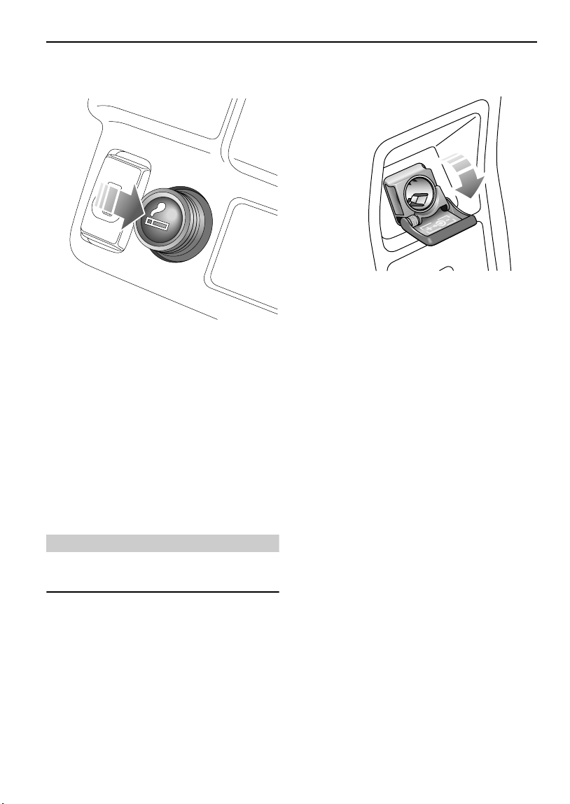
Interior Equipment
CIGAR LIGHTER
H3337
With the starter switch turned on, press the
lighter in to heat up. When it has reached the
correct temperature it will partially eject and
can then be withdrawn for use.
• ONLY hold the cigar lighter by the handle.
• DO NOT plug accessories into the cigar
lighter socket unless they are approved by
Land Rover (see ‘AUXILIARY POWER
SOCKET’, page 87 for more information).
AUXILIARY POWER SOCKET
H3327
An auxiliary power socket is mounted in the
center console, above the rear ashtray. This can
be used to power Land Rover approved
accessories that use a maximum of 180 watts.
Always run the engine during prolonged use of
electrical accessories, otherwise the battery
may become discharged.
CAUTION: NEVER plug non-approved
accessories into the power socket - damage to
the vehicle's electrical systems could occur.
NOTE: On vehicles not fitted with a cigar lighter,
the power socket is protected by a blank cover.
WARNING
Always remove the lighter as a precaution
when children are left alone in the vehicle.
87
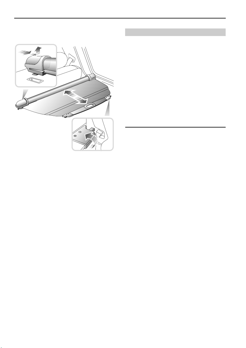
Loadspace Cover
Loadspace Cover
LOADSPACE COVER*
H3328
The rear loadspace can be covered by a spring
loaded roller blind, which can be retracted when
not in use by detaching the cover from the
hooks at the rear of the vehicle (see lower
inset).
To remove the loadspace cover:
1. Slide the retracted cover firmly to the
right.
2. Lift the left hand end of the cover from its
location.
3. Carefully maneuver the cover from the
rear of the vehicle.
WARNING
DO NOT carry loose items of luggage on top of
the loadspace cover - these may obscure
vision and could become dangerous
projectiles in the event of a sudden stop or
collision.
All equipment, luggage or tools carried in the
loadspace should be secured to reduce the
risk of injury to the driver and passengers in
the event of an accident or emergency
maneuver.
DO NOT store the loadspace cover loose in the
vehicle.
Refitting the loadspace cover is the reverse of
the removal procedure.
NOTE: Removal of the loadspace cover may be
eased by folding the rear seat backrest forward.
88

In-Car Telephones
In-Car Telephones
IN-CAR TELEPHONES
For your safety, always note the following
precautions before fitting or using an in-car
telephone, or any mobile communication
equipment.
• Only use an installation kit incorporating an
aerial external to the vehicle.
• Ensure that the installation is carried out by
a competent installer.
WARNING
For your safety and that of others, using any
hand-held appliance while driving can be
dangerous. Always stop the vehicle before
making a call and ensure the telephone is
switched off while you are driving.
89

In-Car Entertainment
In-Car Entertainment
RADIO/CASSETTE PLAYER
NOTE: Full operating instructions for any audio
equipment fitted as standard to your vehicle,
are contained in the `In-car Entertainment'
book in the literature pack.
REMOTE AUDIO CONTROLS*
CD autochanger
The CD autochanger is located under the front
right hand seat. Full operating instructions are
contained in the ‘In-car Entertainment’ book in
the car literature pack.
*
WARNING
DO NOT insert or eject the magazine while
driving - this action could result in the driver
losing control of the vehicle.
RADIO AERIAL
H2330
Your vehicle is equipped with a detachable
mast aerial, mounted on the roof.
NOTE: ALWAYS unscrew and remove the aerial
before entering an automatic car wash.
Aerial height
Always check the available headroom and, if
necessary, adjust the angle of the aerial (see
illustration) before entering or leaving a garage
or car park with insufficient headroom.
H3329A
Volume control
Lift or press down to increase or decrease
volume.
Search control
Lift or press down to search for the next or
previous radio station on the selected
waveband.
During CD play, lift the control to move forward
to the next track, or press down to return to the
start of the current track. Operate the control
repeatedly to move forward or back through
several tracks at a time.
NAVIGATION SYSTEM*
NOTE: Full operating instructions for the
navigation system, if fitted to your vehicle, are
contained in the `Audio and Navigation System'
book in the literature pack.
NOTE: The aerial of the navigation system* (if
fitted) cannot be adjusted for height.
90

Driving & Operating
Starting & Driving
STEERING COLUMN LOCK . . . . . . . . . . . . . . . . . 93
STARTER SWITCH. . . . . . . . . . . . . . . . . . . . . . . . 93
STARTING . . . . . . . . . . . . . . . . . . . . . . . . . . . . . . 94
DRIVING . . . . . . . . . . . . . . . . . . . . . . . . . . . . . . . 95
FUEL ECONOMY . . . . . . . . . . . . . . . . . . . . . . . . . 96
EMISSION CONTROL SYSTEM . . . . . . . . . . . . . . 97
Fuel System
TYPE OF FUEL . . . . . . . . . . . . . . . . . . . . . . . . . . . 98
GAS STATION SAFETY. . . . . . . . . . . . . . . . . . . . . 99
FUEL FILLER . . . . . . . . . . . . . . . . . . . . . . . . . . . . 99
FUEL FILLING . . . . . . . . . . . . . . . . . . . . . . . . . . 100
EMPTY FUEL TANK . . . . . . . . . . . . . . . . . . . . . . 100
FUEL CUT-OFF SWITCH. . . . . . . . . . . . . . . . . . . 100
Catalytic Converter
CATALYTIC CONVERTER. . . . . . . . . . . . . . . . . . 101
Automatic Transmission
CommandShiftTM TRANSMISSION . . . . . . . . . . 103
GEAR SELECTOR LEVER. . . . . . . . . . . . . . . . . . 103
USING AN AUTOMATIC GEARBOX . . . . . . . . . . 105
AUTOMATICALLY SELECTED MODES . . . . . . . . 107
Hill Descent Control
HILL DESCENT CONTROL . . . . . . . . . . . . . . . . . 108
Cruise Control
CRUISE CONTROL. . . . . . . . . . . . . . . . . . . . . . . 110
Brakes
FOOT BRAKE . . . . . . . . . . . . . . . . . . . . . . . . . . . 112
PARKING BRAKE. . . . . . . . . . . . . . . . . . . . . . . . 114
ANTI-LOCK BRAKES . . . . . . . . . . . . . . . . . . . . . 115
Traction Control
ELECTRONIC TRACTION CONTROL. . . . . . . . . . 117
Hardback
REMOVING AND FITTING THE HARDBACK . . . . 118
Roof Bars
REMOVING AND FITTING THE ROOF BARS. . . . 121
91

Load Carrying
LUGGAGE ANCHOR POINTS. . . . . . . . . . . . . . . 124
STOWAGE BOX. . . . . . . . . . . . . . . . . . . . . . . . . 124
VEHICLE LOADING . . . . . . . . . . . . . . . . . . . . . . 125
ROOF RACK . . . . . . . . . . . . . . . . . . . . . . . . . . . 125
Towing
TOW BARS . . . . . . . . . . . . . . . . . . . . . . . . . . . . 126
TOWING A TRAILER. . . . . . . . . . . . . . . . . . . . . 126
92

Starting & Driving
Driving & Operating
Starting & Driving
STEERING COLUMN LOCK
H3522
To unlock the steering column
Insert the key FULLY and turn the starter switch
to position ‘I’. A small movement of the steering
wheel may be necessary to disengage the
steering lock while turning the switch.
STARTER SWITCH
The starter switch is located to the right of the
steering column, and uses the following
sequence of key positions to operate the
steering lock, electrical circuits and starter
motor:
Position ‘0’
• Steering locked (if key is removed).
• Most lighting circuits are operational,
including: sidelights, headlights and hazard
warning lights.
• Gear selector lever locked in ‘P’.
Position ‘I’
• Steering unlocked.
• Clock, radio/cassette player and cigar lighter
can now be operated.
Position ‘II’
• All instruments, warning lights and
electrical circuits are operational.
To lock the steering column
With the gear selector in ‘P’ (Park), turn the key
to position ‘0’ and withdraw the key from the
starter switch. Turn the steering wheel slightly
until the lock engages.
WARNING
To prevent loss of steering control, do not
under any circumstances turn the key to the
'O' position while the vehicle is moving. To
prevent the steering column lock engaging it
is most important that, before the vehicle is
moved in any way, the key be inserted in the
lock and turned to position 'I'. If, due to an
accident or electrical fault, it is not safe to
turn the key, disconnect the negative lead of
the battery and then turn the key.
Position ‘III’
• Starter motor operates.
Release the key immediately the engine
starts (the key will automatically return to
position ‘II’). Note that operation of position
‘I’ electrical functions will be interrupted
during engine cranking.
NOTE: Gear selector position ‘P’ or ‘N’ must be
selected before the engine will start.
NOTE: Gear selector position ‘P’ must be
selected before the key can be removed from
the starter switch.
NOTE: Immediately after the engine is started, a
short, low pitched ‘buzz’ may be heard; this is
the ABS system priming and is no cause for
concern.
93

Starting & Driving
STARTING
WARNING
Never start or leave the engine running in an
unventilated building - exhaust gases are
poisonous and contain carbon monoxide,
which can cause unconsciousness and may
even be fatal.
Before starting the engine and driving, ENSURE
you are familiar with the precautions shown
under ‘CATALYTIC CONVERTER’, page 101.
In particular, you should be aware that if the
engine fails to start, continued use of the starter
may result in unburnt fuel damaging the
catalytic converter.
1. Check that the parking brake is applied
and that the gear selector is ‘P’ (Park) or
‘N’ (Neutral).
2. Switch off all unnecessary electrical
equipment (including the air
conditioning).
3. Turn the starter switch to position ‘III’ to
operate the starter motor. DO NOT press
the accelerator pedal while starting, and
RELEASE THE KEY as soon as the engine
is running.
DO NOT pump the accelerator pedal during
starting.
In temperate climates, DO NOT operate the
starter for longer than 15 seconds. If the engine
fails to start, switch off and wait for at least 10
seconds before trying again.
NOTE: Continued use of the starter will not only
discharge the battery, but may cause damage to
the starter motor and the catalytic converter.
NOTE: The battery charging, oil pressure and
engine malfunction indicator warning lights
should extinguish as soon as the engine is
running.
After starting, ensure that the parking brake and
foot brake are firmly applied and the accelerator
pedal is not depressed while moving the gear
selector lever from ‘N’ or ‘P’, otherwise, the
vehicle may move immediately the selector
lever is moved to one of the drive positions
(1, 2, 4, D or R). This is particularly important
when the engine is cold, because the engine will
be idling at a faster speed than normal.
NOTE: The selector lever cannot be moved from
‘P’ into a drive position while the engine is
running, unless the brake pedal is applied.
Cold climates
The engine of your Freelander is fitted with an
advanced ‘drive by wire’ engine management
system. This is designed to optimise the
vehicle’s cold start behaviour - pressing the
accelerator pedal has no effect on starting
performance.
At temperatures down to -15°F (-26°C), the
engine should start within 5 to 8 seconds.
Below this temperature, engine cranking times
will increase significantly and the starter motor
may need to be operated continuously for as
long as 30 seconds before the engine will start.
For this reason, ensure that all non-essential
electrical equipment is switched off.
In very cold climates the oil pressure warning
light may take several seconds to extinguish.
Sump Heater (Canadian specification only)
If the vehicle is left in temperatures of -15°F
(-25°C) or lower, the sump oil heater should be
used to improver the engine’s starting
characteristics.
The heater plug is clipped behind the lower
radiater grille. Unclip the cable adjacent to the
plug and pull the plug through the grille.
Remove the protective cover from the plug then
connect it to an appropriate mains supply cable
socket.
*
94

Starting & Driving
The cover should always be refitted when the
the heater is unplugged from the mains socket
to prevent ingress of dirt, snow or other
contaminants. It is also recommended that the
cable and plug is wire tied to one of the upright
grille supports for easy use if the heater is to be
used regularly.
DRIVING
WARNING
Vehicle stability
Your vehicle has a higher ground clearance
and, hence, a higher center of gravity than
ordinary passenger cars to enable the vehicle
to perform in a wide variety of different
off-road applications. An advantage of the
higher ground clearance is a better view of
the road, allowing the driver to more easily
anticipate problems. Inexperienced drivers
should take additional care, remembering
that the Freelander is not designed for
cornering at the same speeds as conventional
passenger cars, any more than a low slung
sports car is designed to perform
satisfactorily in off-road conditions. As with
other vehicles of this type, failure to operate
the Freelander correctly may result in loss of
control or even vehicle rollover.
Before driving
Learn the layout and function of all the warning
lights and controls, and adjust the seat to a
comfortable driving position, from which you
can ensure full control of the vehicle.
Always start the engine and operate the
controls from the driving position.
Instruments and warning lights
Before driving it is important to fully
understand the function of the instruments and
warning lights.
NOTE: Red warning lights are of particular
importance; illumination indicates that a
safety-related problem or potentially serious
mechanical fault exists. If a red light
illuminates, always stop the vehicle and seek
qualified assistance before continuing.
Warming-up
DO NOT warm-up the engine by allowing it to
idle at a slow speed.
In the interests of fuel economy, it is advisable
to drive the vehicle straight away, remembering
that harsh acceleration and labouring the
engine before the normal operating
temperature has been reached can damage the
engine.
Vehicle Height
The overall height of your vehicle exceeds that
of ordinary passenger cars (for convenience the
height is shown on the underside of the sun
visor). Always be aware of the height of your
vehicle and check the available headroom
before driving through low entrances. This is
particularly important if the vehicle is fitted with
a roof rack or if a sunroof is open.
Parking
WARNING
After bringing the vehicle to a stop, ALWAYS
apply the parking brake and select ‘P’ (Park)
before releasing the foot brake and switching
off the engine.
Switching off
With ‘P’ (Park) selected, return the starter
switch to position ‘I’ and then to position ‘0’ to
remove the key.
NOTE: The key cannot be removed from the
starter switch unless the gear selector is in the
‘P’ (Park) position.
95

Starting & Driving
Breaking-in
Proper breaking-in will have a direct bearing on
the reliability and smooth running of your
vehicle throughout its life.
In particular, the engine, gearbox, brakes and
tires need time to ‘bed-in’ and adjust to the
demands of everyday motoring. During the first
600 miles (1000 km), it is essential to drive with
consideration for the breaking-in process and
heed the following advice:
• LIMIT maximum road speed to 70 mph
(110 km/h) or 3,000 rev/min. Initially, drive
the vehicle on a light throttle and only
increase engine speeds gradually once the
breaking-in distance has been completed.
• DO NOT operate at full throttle or allow the
engine to labour in any gear.
• AVOID fast acceleration and heavy braking
except in emergencies.
After the breaking-in distance has been
completed, engine speeds may be gradually
increased.
FUEL ECONOMY
Fuel consumption is influenced by two major
factors:
• How your vehicle is maintained.
• How you drive your vehicle.
To obtain optimum fuel economy, it is essential
that your vehicle is maintained in accordance
with the manufacturer's service schedule.
Items such as the condition of the air cleaner
element, tire pressures and wheel alignment
will have a significant effect on fuel
consumption. But, above all, the way in which
you drive is most important. The following hints
may help you to obtain better value from your
motoring:
• Avoid unnecessary, short, start-stop
journeys.
• Avoid fast starts by accelerating gently and
smoothly from rest.
• Do not drive in the lower gears for longer
than necessary.
• Decelerate gently and avoid sudden and
heavy braking.
• Anticipate obstructions and adjust your
speed accordingly well in advance.
• When stationary in traffic, select neutral to
improve fuel economy and air conditioning
performance.
96

Starting & Driving
EMISSION CONTROL SYSTEM
WARNING
Exhaust fumes contain poisonous substances
which can cause unconsciousness and may
even be fatal.
• DO NOT inhale exhaust gases.
• DO NOT start or leave the engine running
in an enclosed unventilated area, or drive
with the taildoor open.
• DO NOT modify the exhaust system from
the original design.
• ALWAYS repair exhaust system leaks
immediately.
• If you think exhaust fumes are entering the
vehicle have the cause determined and
corrected immediately.
Land Rover vehicles are fitted with emission
and evaporative control equipment necessary
to meet a number of territorial requirements.
In many countries it is against the law for
vehicle owners to modify or tamper with
emission control equipment, or to sanction the
unauthorised replacement or modification of
this equipment. In such cases the vehicle owner
and the repairer may both be liable for legal
penalties.
It is important to remember that all Land Rover
retailers are properly equipped to perform
repairs and to maintain the emission control
system on your vehicle.
97

Fuel System
Fuel System
TYPE OF FUEL
IMPORTANT INFORMATION
ONLY USE UNLEADED FUEL
• Unleaded fuel is essential for proper
operation of the emission control
system.
DO NOT use leaded fuel! Your engine is
designed to use unleaded fuel ONLY.
• Even a very small quantity of leaded
fuel will damage your vehicle's
emission control system and could
invalidate the emissions warranty. In
addition, leaded fuel will damage the
oxygen sensors in the fuel injection
system and also seriously damage the
catalyst in the catalytic converter.
Fuel system cleaning agents should be
avoided, as many of these products can
be harmful to gaskets and other materials
used in fuel system components.
Octane requirements
Unleaded gasoline with a CLC or AKI minimum
octane rating of 87 is recommended.
If heavy engine knock is detected when using
the recommended octane rated fuel, or if steady
engine knocking is present while maintaining a
steady speed on level roads, contact your
retailer for advice.
NOTE: An occasional, light, engine knock while
accelerating or climbing hills is acceptable.
Octane enhancers
The use of octane enhancers is not
recommended, and may invalidate the vehicle
warranty.
NOTE: Reformulated gasolines and gasolines
that contain detergents, anti-corrosion and
stability additives are recommended - they will
help your vehicle maintain the correct level of
emissions and engine performance.
Driveability
If you encounter driveability, starting and
stalling problems, especially in high ambient
temperatures or at high altitude when the
engine is cold, it may be caused by poor quality
fuel. Try an alternative brand, and if the problem
persists, seek advice from your retailer.
NOTE: Federal law requires that gasoline octane
ratings be posted on the pumps. The Cost of
Living Council (CLC) octane rating or Anti
Knock Index (AKI) octane rating shown is an
average of Research Octane Number (RON) and
Motor Octane Number (MON).
NOTE: Engine performance and fuel economy
may improve if higher octane fuel is used.
Using unleaded fuel with an octane rating lower
than that recommended above may reduce
performance and economy and can also cause
persistent, heavy ‘engine knock’ (a metallic
rapping noise). If severe, this can lead to engine
damage.
Gasoline/oxygenated fuel blends
To avoid invalidating the vehicle warranty, use
ONLY fuels blended within the following limits:
• Up to 15% of Methyl Tertiary Butyl Ether
(MTBE) and unleaded fuel mix.
• Up to 15% of Ethyl Tertiary Butyl Ether
(ETBE) and unleaded fuel mix.
• Up to 10% of Ethanol (Ethyl or grain
alcohol) and unleaded fuel mix.
98

Fuel System
Methanol/unleaded fuel blends
In some areas, it is possible to buy unleaded
fuel that is blended with up to 5% Methanol
(Methyl or wood alcohol) and cosolvents and
corrosion preventatives. Using these blends
can cause driveability problems and damage to
the fuel system components. Their use may
also invalidate the vehicle warranty.
WHEREVER POSSIBLE, AVOID USING FUEL
CONTAINING METHANOL!
WARNING
Automotive fuels can cause serious injury,
and even death if misused.
Methanol/unleaded fuel blends, even in small
amounts, can cause blindness and possible
death if swallowed. Additionally, take
precautions to prevent methanol from coming
into contact with the skin.
GAS STATION SAFETY
Always take sensible precautions when
refuelling:
• Switch off the engine.
• Do not smoke or introduce other ignition
sources.
• Switch off mobile phones.
• Take care not to spill fuel.
• Do not overfill the tank.
• Do not fill gas cans in the vehicle.
• Use only the hold-open latch provided on
the gasoline pump. Never jam the latch open
with some other object.
WARNING
Petroleum gases are highly inflammable and,
in confined spaces, are also extremely
explosive.
Always place portable gasoline containers on
the ground while filling. A fire may result if
gasoline is pumped into a container that is
inside a vehicle or on a truck bed. You could
be burned!
FUEL FILLER
H3376
The fuel filler is located in the rear right-hand
fender. Insert the key in the lock, turn it
anti-clockwise and allow any pressure inside
the tank to escape, before removing the cap.
NOTE: The key cannot be removed from the
filler cap unless the cap is correctly positioned
in the filler neck.
99

Fuel System
FUEL FILLING
Gas station pumps are equipped with automatic
cut-off sensing to avoid fuel spillage. Fill the
tank SLOWLY until the filler nozzle
automatically cuts-off the supply. DO NOT
attempt to fill the tank beyond this point or
spillage could result due to expansion of the
fuel.
The fuel filler neck will accept ONLY a narrow
filler nozzle of the type found on pumps that
deliver UNLEADED fuel. A flap lies across the
filler neck; insert the nozzle sufficiently to fully
open the flap before filling.
Filling difficulties
The fuel delivery rate of gas station pumps can
vary significantly. This, coupled with the fact
that modern pumps are equipped with a sensor
which automatically cuts off the supply as soon
as turbulence is detected in the upper part of
the vehicle's filler neck, could result in isolated
fuel filling problems.
EMPTY FUEL TANK
NEVER allow the vehicle to run out of fuel - the
resultant misfire may destroy the catalytic
converter.
In the event of a fuel tank running dry, contact
your Land Rover retailer before attempting to
start the engine.
FUEL CUT-OFF SWITCH
H3996
The fuel cut-off switch is a safety device which,
in the event of a collision or sudden impact,
automatically cuts off the fuel supply to the
engine.
The switch is located inside the engine
compartment on the left hand side, beneath,
and to the rear of, the engine compartment fuse
box (a label attached to the bulkhead will assist
location of the switch). If the switch has been
activated, it must be reset by pressing the
rubber top (arrowed in illustration) before the
engine can be restarted.
See also ‘DOOR LOCKING CUT-OFF SWITCH’,
page 32.
WARNING
Always check for fuel leaks before resetting
the switch! Activating the switch when the
fuel system has been damaged (evidenced by
fuel leakage and odour) will cause additional
fuel leakage, increasing the risk of fire and
personal injury.
100
 Loading...