

Page 1
OWNER’S HANDBOOK
Publication Part No. LRL 18 02 54 701
Page 2

About this handbook
This handbook forms part of the Owner literature supplied with your new vehicle. Right hand drive
and left hand drive conditions may be shown in the graphics and where information is specific to a
particular country, it is indicated as such.
The Quick Start section is designed to rapidly familiarise the driver with the initial set up and also
explain some of the unique features. Please take the time to study the operating instructions with
your vehicle as soon as you can.
Important
The information contained in this handbook covers all vehicle derivatives and optional equipment.
Some of the options may not be fitted to your vehicle, unless they formed part of the original vehicle
specification. Therefore, some parts of this handbook may not apply to your vehicle. Furthermore,
due to printing cycles, it may include descriptions of options before they become generally available.
The information contained in this publication was correct when it went to print. Vehicle design
changes may have been made after this handbook was printed. When this occurs, a handbook
supplement is added to the literature pack. Subsequent updates can be viewed on the Land Rover
internet site at; www.ownerinfo.landrover.com.
In the interest of development, the right is reserved to change specifications, design or equipment
at any time without notice and without incurring any obligations. This publication, or part thereof,
may not be reproduced, not translated, without our approval. Errors and omissions excepted. All
rights reserved. No part of this publication may be reproduced, stored in a retrieval system or
transmitted in any form, electronic, mechanical, photocopying, recording or other means, without
prior written permission from Land Rover Customer Services.
© Land Rover 2006
All rights reserved.
Published by Land Rover Technical Communications.
2
Page 3

Handbook Contents
Quick Start
Quick Start . . . . . . . . . . . . . . . . . . . . . . . . . . 7
Gas Station Information . . . . . . . . . . . . . . . 33
General Information
General Information . . . . . . . . . . . . . . . . . . 35
Reporting Safety Defects . . . . . . . . . . . . . . 38
Parts and Accessories . . . . . . . . . . . . . . . . 39
Controls and Instruments
Keys and Remote Controls. . . . . . . . . . . . . 41
Locks and Alarms . . . . . . . . . . . . . . . . . . . 46
Seats . . . . . . . . . . . . . . . . . . . . . . . . . . . . . 54
Seat Belts . . . . . . . . . . . . . . . . . . . . . . . . . . 62
Child Restraints . . . . . . . . . . . . . . . . . . . . . 67
Supplementary Restraint Systems . . . . . . . 72
Steering Column . . . . . . . . . . . . . . . . . . . . 80
Door Mirrors . . . . . . . . . . . . . . . . . . . . . . . 81
Instruments . . . . . . . . . . . . . . . . . . . . . . . . 83
Trip Computer . . . . . . . . . . . . . . . . . . . . . . 85
Settings Option . . . . . . . . . . . . . . . . . . . . . 86
Message Center . . . . . . . . . . . . . . . . . . . . . 88
Warning Indicators. . . . . . . . . . . . . . . . . . 100
Audible Warnings. . . . . . . . . . . . . . . . . . . 106
Lamps and Indicators . . . . . . . . . . . . . . . 107
Wipers and Washers . . . . . . . . . . . . . . . . 110
Horn. . . . . . . . . . . . . . . . . . . . . . . . . . . . . 114
Electric Windows . . . . . . . . . . . . . . . . . . . 115
Sunroof . . . . . . . . . . . . . . . . . . . . . . . . . . 117
Heating and Ventilation . . . . . . . . . . . . . . 119
Interior Lamps . . . . . . . . . . . . . . . . . . . . . 126
Interior Equipment . . . . . . . . . . . . . . . . . . 128
Loadspace Cover . . . . . . . . . . . . . . . . . . . 135
In-Car Telephones . . . . . . . . . . . . . . . . . . 137
Voice Recognition . . . . . . . . . . . . . . . . . . 138
Land Rover Homelink® . . . . . . . . . . . . . . 140
Driving and Operating
Starting and Driving . . . . . . . . . . . . . . . . . 144
Fuel and Refuelling. . . . . . . . . . . . . . . . . . 151
Park Distance Control. . . . . . . . . . . . . . . . 155
Automatic Transmission . . . . . . . . . . . . . 157
Transfer Gearbox . . . . . . . . . . . . . . . . . . . 162
Cruise Control . . . . . . . . . . . . . . . . . . . . . 165
Adaptive Cruise Control (ACC) . . . . . . . . . 167
Brakes . . . . . . . . . . . . . . . . . . . . . . . . . . . 174
Dynamic Stability and Traction Control . . 179
Hill Descent Control . . . . . . . . . . . . . . . . . 181
Air Suspension. . . . . . . . . . . . . . . . . . . . . 184
Dynamic Response . . . . . . . . . . . . . . . . . 190
Terrain Response . . . . . . . . . . . . . . . . . . . 191
Towing . . . . . . . . . . . . . . . . . . . . . . . . . . . 198
Towing Eyes. . . . . . . . . . . . . . . . . . . . . . . 205
Towing the Vehicle . . . . . . . . . . . . . . . . . . 208
Load Carrying. . . . . . . . . . . . . . . . . . . . . . 210
Front Lighting Systems . . . . . . . . . . . . . . 211
Maintenance
Maintenance. . . . . . . . . . . . . . . . . . . . . . . 213
Hood Opening . . . . . . . . . . . . . . . . . . . . . 216
Under-hood Covers . . . . . . . . . . . . . . . . . 217
Engine Compartment . . . . . . . . . . . . . . . . 218
Engine Oil. . . . . . . . . . . . . . . . . . . . . . . . . 220
Cooling System . . . . . . . . . . . . . . . . . . . . 221
Brakes . . . . . . . . . . . . . . . . . . . . . . . . . . . 223
Power Steering. . . . . . . . . . . . . . . . . . . . . 224
Dynamic Response . . . . . . . . . . . . . . . . . 225
Washers . . . . . . . . . . . . . . . . . . . . . . . . . . 226
Wiper Blades . . . . . . . . . . . . . . . . . . . . . . 228
Battery . . . . . . . . . . . . . . . . . . . . . . . . . . . 229
Tires . . . . . . . . . . . . . . . . . . . . . . . . . . . . . 233
Tire Pressure Monitoring System. . . . . . . 246
Cleaning and Vehicle Care . . . . . . . . . . . . 250
Identification Numbers. . . . . . . . . . . . . . . 253
3
Page 4

Handbook Contents
Roadside Emergency
Wheel Changing . . . . . . . . . . . . . . . . . . . . 254
Emergency Starting . . . . . . . . . . . . . . . . . 263
Fuses . . . . . . . . . . . . . . . . . . . . . . . . . . . . 265
Bulb Replacement. . . . . . . . . . . . . . . . . . . 272
Technical Data
Lubricants and Fluids . . . . . . . . . . . . . . . . 287
Capacities . . . . . . . . . . . . . . . . . . . . . . . . . 288
Engines. . . . . . . . . . . . . . . . . . . . . . . . . . . 289
Wheels and Tires . . . . . . . . . . . . . . . . . . . 290
Weights . . . . . . . . . . . . . . . . . . . . . . . . . . 291
Dimensions. . . . . . . . . . . . . . . . . . . . . . . . 292
Audio System
Radio Reception . . . . . . . . . . . . . . . . . . . . 293
Care of Compact Discs . . . . . . . . . . . . . . . 294
Controls and Settings . . . . . . . . . . . . . . . . 295
Auxiliary Connections . . . . . . . . . . . . . . . . 307
Radio . . . . . . . . . . . . . . . . . . . . . . . . . . . . 309
Satellite Radio. . . . . . . . . . . . . . . . . . . . . . 316
CD Operation . . . . . . . . . . . . . . . . . . . . . . 330
Audio Voice Recognition. . . . . . . . . . . . . . 338
Radio Commands . . . . . . . . . . . . . . . . . . . 341
CD Commands . . . . . . . . . . . . . . . . . . . . . 345
Rear Seat Entertainment Commands . . . . 346
4
Page 5

Quick Start
Quick Start
THE REMOTE CONTROL . . . . . . . . . . . . . . . .7
CENTRAL LOCKING . . . . . . . . . . . . . . . . . . . .8
EMERGENCY UNLOCKING . . . . . . . . . . . . . .8
TAILGATE . . . . . . . . . . . . . . . . . . . . . . . . . . .9
HOOD . . . . . . . . . . . . . . . . . . . . . . . . . . . . . .9
SEAT ADJUSTMENT - POWER SEATS . . . .10
DRIVING POSITION MEMORY . . . . . . . . . .10
STEERING COLUMN ADJUSTMENT . . . . . .11
PARKBRAKE (EPB) . . . . . . . . . . . . . . . . . . .11
WINDOWS/DOOR MIRRORS . . . . . . . . . . .12
SEAT BELTS/CHILD RESTRAINTS . . . . . . .13
PASSENGER AIR BAG . . . . . . . . . . . . . . . . .13
HEATING AND VENTILATION . . . . . . . . . . .14
FACIA CONTROLS . . . . . . . . . . . . . . . . . . . .16
FACIA CONTROLS KEY . . . . . . . . . . . . . . . .17
WARNING INDICATORS . . . . . . . . . . . . . . .18
LAMPS MASTER SWITCH . . . . . . . . . . . . . .19
STEERING COLUMN LEVERS . . . . . . . . . . .20
CONFIGURABLE FEATURES . . . . . . . . . . . .21
OVERHEAD CONSOLE . . . . . . . . . . . . . . . . .22
REAR VIEW MIRROR . . . . . . . . . . . . . . . . .23
AUTOMATIC TRANSMISSION . . . . . . . . . . .24
HILL DESCENT CONTROL (HDC) . . . . . . . .25
TRANSFER GEARBOX . . . . . . . . . . . . . . . . .25
TERRAIN RESPONSE SYSTEM . . . . . . . . . .26
AIR SUSPENSION . . . . . . . . . . . . . . . . . . . .27
CRUISE CONTROL . . . . . . . . . . . . . . . . . . .27
AUDIO SYSTEM OPERATION . . . . . . . . . . .28
RADIO OPERATION . . . . . . . . . . . . . . . . . . .29
CD OPERATION . . . . . . . . . . . . . . . . . . . . . .30
VOICE RECOGNITION . . . . . . . . . . . . . . . . .32
Gas Station Information
FUEL FILLER . . . . . . . . . . . . . . . . . . . . . . . .33
TIRE PRESSURES . . . . . . . . . . . . . . . . . . . .34
5
Page 6

6
Page 7
Quick Start
THE REMOTE CONTROL
LAN0114G
1. Key release button.
Press to release the folded key.
2. Lock button.
Locks all doors and activates perimetric
alarm.
See Perimetric alarm, 47.
3. Unlock button.
Press once to disarm all alarm features and
unlock driver’s door only. Press twice to
open all doors.
Note: The above applies unless configured
for multi-point entry.
See Single-point entry, 44.
4. Land Rover button.
The remote control can be programmed to
initiate one of 5 features; Panic alarm,
Headlamp courtesy delay, Tailgate release,
Tailglass release or Air suspension control.
See LAND ROVER BUTTON, 42.
Quick Start
Single point entry
This is a security feature that unlocks only the
driver’s door. It can be disabled on individual
1
2
3
4
remote controls by simultaneously pressing
and holding buttons 2 and 3 for three
seconds. The vehicle will lock and then
unlock in the currently selected mode to
confirm the change.
You can now unlock all doors with a single
press. Repeating the procedure will re-enable
Single point entry.
Automatic relock
If the vehicle is unlocked with the remote
control, it will automatically relock and arm the
alarm if a door or the tailgate is not opened
within one minute.
Partial arming
If an aperture (door, hood or tailgate) is not
fully closed when the remote control lock
button is pressed, the horn will sound briefly
to signal that an aperture is still open. The
alarm will remain disarmed and all of the
closed apertures will lock.
As soon as the open aperture is closed, the
system will automatically arm, signalled by
three flashes of the hazard warning lamps.
7
Page 8
Quick Start
CENTRAL LOCKING
1 23
LAN0121N
Master lock and unlock switches
1. Press to unlock all doors and tailgate.
2. Press to lock all doors and tailgate.
3. Press both buttons simultaneously for
three seconds to release the tailgate.
Speed related locking
If enabled, the doors and tailgate will
automatically lock when the vehicle’s speed
exceeds 8 km/h (5 mph).
This feature can be disabled or enabled in the
SETTINGS menu of the trip computer.
See SELECTING SETTINGS OPTION, 86.
EMERGENCY UNLOCKING
LAN0116G
If the remote control should fail, there is an
emergency access feature on the left-hand front
door lock. With the key inserted into the slot
beneath the handle cap, the cap can be pulled
outwards slightly and then moved backwards to
unhook it. The key can now be used to unlock
the vehicle.
See Emergency locking/unlocking, 50.
8
Page 9
Quick Start
TAILGATE
1
2
LAN0394G
Opening the tailgate
With all the doors unlocked, press the release
button 1 on the tailgate to release.
The tailgate incorporates a ‘Power closure’
feature, which removes the need to ‘slam’ the
tailgate when closing.
Opening the tailglass
With all the doors unlocked, press the touch
pad 2 on the exterior handle and pull to open.
Operating note
If the vehicle is locked/unlocked 10 times
within a short period, the door and tailgate
latches will be disabled for approximately one
minute, to protect the battery and lock
mechanism.
HOOD
2
3
1
LAN0395G
Opening
Pull the hood release lever 1 located on the
left-hand side of the vehicle.
Lift the hood safety catch lever 2, located on the
front edge of the hood beneath the center point
of the words LAND ROVER and raise the hood.
Closing
Lower the hood until it is 300 mm (12 inches)
from its closed position. Using the palms of
both hands positioned on the front edge of the
hood on either side of the radiator grille, push
down until the catches ‘click’.
Check that both catches 3 are engaged by trying
to lift the front edge of the hood.
9
Page 10
Quick Start
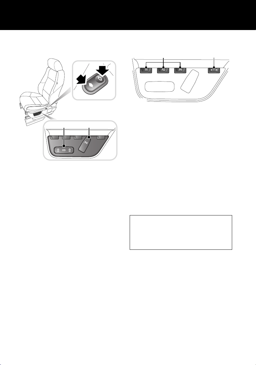
SEAT ADJUSTMENT - POWER SEATS
(Driver’s seat only)
3
1
LAN0396G
To adjust the seats, the starter switch must be
in position I or II.
1. Seat recline.
2. Seat fore/aft, cushion height and front tilt
control.
3. Lower backrest lumbar support.
Power operated memory driver’s seat also has
a 10 minute active period (Non-memory power
operated seats up to 15 minutes) initiated
when:
• The driver’s door is opened/closed.
• The starter key is turned to the off position.
See FRONT SEAT ADJUSTMENT, 55.
2
DRIVING POSITION MEMORY
2
LAN0397G
Once you have adjusted the driver’s seat and
exterior mirrors, the vehicle can memorise
these settings for future use.
1. Press the memory store button 1 to
activate the memory function for five
seconds.
2. Press one of the preset buttons 2 within
five seconds to memorise the current
settings. MEMORY STORED will be
displayed in the message center
accompanied by an audible chime to
confirm the settings have been memorised.
To recall a stored driving position, press the
appropriate preset button 2.
Operating note
A seat position will only be memorised during
the five second active period.
Any existing settings will be over-written
when programming a memory position.
Lazy entry
When this feature is enabled, the vehicle stores
the seating and mirror positions for each
remote control. Next time the vehicle is
unlocked using a remote control, the position of
the seat and mirrors will adjust to the last used
position.
This feature can be disabled or enabled in the
Settings option accessed via the trip computer.
1
10
Page 11
Quick Start
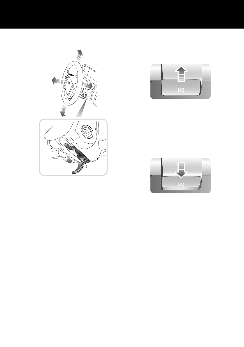
STEERING COLUMN ADJUSTMENT
LAN0398G
1. Move the lever located under the steering
wheel fully downward.
2. Adjust the height and reach of the steering
wheel to the desired position.
3. Move the lever fully up to lock the position
of the wheel.
See STEERING COLUMN ADJUSTMENT, 80.
PARKBRAKE (EPB)
Applying
LAN0406G
With the vehicle stationary, pull up the
parkbrake lever and release it. The lever will
return to a neutral position and the red warning
indicator in the instrument pack will illuminate.
Releasing
LAN0407G
The starter switch must be in position I or II.
Apply the footbrake and press down on the
parkbrake lever.
If the vehicle is stationary with the parkbrake
applied and either D (Drive) or R (Reverse)
selected, pressing the accelerator will
automatically release the parkbrake.
For more detailed information on the parkbrake,
see PARKBRAKE (EPB), 177.
11
Page 12
Quick Start
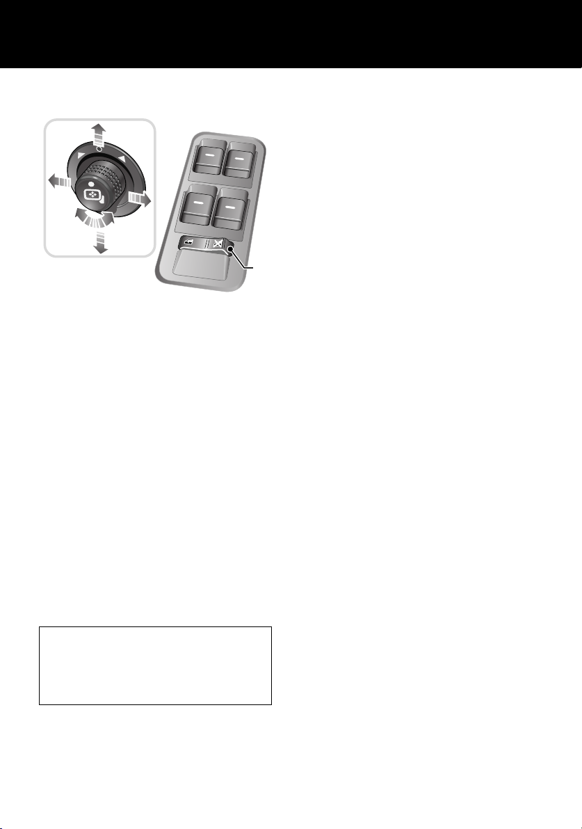
WINDOWS/DOOR MIRRORS
1
2
LAN0399G
Windows
• To open a window, press and hold the
respective switch.
• To close the window, pull and hold the
switch.
Window movement can be stopped at any time
by releasing the switch.
See ELECTRIC WINDOWS, 115.
One touch operation (front doors only)
Press/lift the switch briefly to open or close the
window in one movement. Window movement
can be stopped at any time by pressing the
switch again.
Rear window isolation switch
Press the right-hand side of switch 2 to inhibit
the operation of the rear window switches.
Door mirror adjustment
To adjust the mirrors, rotate the mirror
adjustment knob 1 left or right to select the
appropriate mirror. Move the knob in any
direction to adjust the position of the mirror
glass. See EXTERIOR MIRRORS, 81.
Reverse automatic mirror dip
With the feature enabled, when reverse gear is
selected the door mirrors will dip.
The dip position of the door mirrors can be
personalised. See Reverse mirror dipping, 82.
This feature can be disabled or enabled in the
Settings option accessed via the trip computer.
See SELECTING SETTINGS OPTION, 86.
Resonance with lowered windows
If a resonance/booming sound occurs when a
rear window is open, lowering an adjacent
front window about 25 mm (1 inch) will
eliminate the condition.
12
Page 13
Quick Start
SEAT BELTS/CHILD RESTRAINTS
A warning indicator in the
instrument pack will illuminate to
alert you that the driver’s and/or
front passenger’s seat belt is unbuckled. An
intermittent chime may also be heard.
Automatic Locking Reels (ALR)
All passenger seat belts have ALR fitted for use
with child seats or securing large items.
• To engage: extend seat belt to maximum
length to enable locking mechanism.
• Allow seat belt to retract onto the child
seat/large item (a clicking sound will be
heard as the belt retracts). Ensure there is
no slack by pressing the seat/item firmly
into the vehicle seat.
• To disengage: unbuckle belt and allow belt
to fully retract.
With ALR enabled, as the seat belt retracts, it
will automatically lock, preventing
re-extension.
Ensure passengers do not fully extend the
restraints and inadvertently engage this
feature during normal use.
Child Seats
It is important to remember that the child’s
weight, rather than age, determines the type of
seat that is required.
See CHILD SEATS, 67.
Recommended child seat
Land Rover strongly recommends the use of
LATCH (Lower Anchors and Tethers for
CHildren) child seats.
LATCH child seats can only be fitted in the
rear, outer seating positions.
PASSENGER AIR BAG
PASS
AIRBAG
OFF
PASS
AIRBAG
123
ABC DEF
456
JKL MNOGHI
789
TUV WXYZPQRS
LAN0759N
0
The front passenger seat is fitted with an
occupancy detection system that determines
the state of seat occupancy and sets the air bag
status to suit.
• Seat unoccupied - air bag deactivated and
indicator off.
• Seat occupied - air bag activated and
indicator off.
• Seat occupied by a child seat or low weight
object - air bag deactivated and indicator
on.
See Occupant detection, 77.
Operating note
If the indicator becomes permanently
illuminated when the seat is definitely empty,
please contact your Land Rover Dealer
immediately.
OFF
6CD-465
13
Page 14
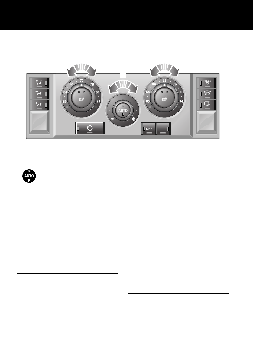
HEATING AND VENTILATION
Quick Start
1
LAN0762N
AUTO (Automatic) MODE
Press AUTO to select automatic
operation of the system, both
LEDs in the switch will illuminate.
The system adjusts heat output, blower speed,
air intake and airflow distribution to maintain
your the selected temperature(s) and reduce
misting without further adjustments.
Use the air distribution and blower controls to
adjust the automatic settings. The appropriate
LED in the AUTO control will extinguish.
Recommended mode
Select AUTO as the normal operating mode.
This will help prevent window misting and
odours from the climate control system.
Air conditioning
Air conditioning provides cooled and
dehumidified air for occupant comfort. Dry
airflow is effective in preventing misting of
windows and is also beneficial at low external
temperatures.
1
2
ECON
Air conditioning is automatically switched on
and controlled whenever the system is not
operating in ‘Economy’ mode.
External water deposits
The air conditioning system removes
moisture from the air and deposits excess
water beneath the vehicle. Puddles may form,
but this is normal and no cause for concern.
Temperature selection
Rotate the controls 1 to adjust the temperature
for the respective side of the passenger
compartment.
Operating note
It is not possible to achieve a temperature
differential of more than 4°C (7°F) between
left and right.
14
Page 15
Quick Start
Blower speed
Rotate the control 2 to adjust the airflow. LEDs
will illuminate to indicate which of the eight
possible speeds is currently selected.
Air distribution control
Press to select a distribution setting. An LED
will illuminate in the switch.
Windshield and side window vents
Face level vents
Foot level vents
More than one setting can be selected.
Air recirculation
Press to activate air recirculation.
An LED will illuminate in the
switch. Press again to return to
fresh air intake.
OFF
Press to switch the system off. An
LED will illuminate in the switch.
Press again to return the system to
its previous operating mode. The system will
also be reactivated by using the AUTO, blower
speed, air distribution or defrost controls.
Economy mode
Press to select ‘Economy’ mode.
An LED will illuminate in the
switch.
Air conditioning is switched off to reduce load
on the engine and improve fuel consumption.
Seat heaters
Press the relevant button to
operate the required seat heater at
high level. Both LEDs in the switch
will illuminate.
Press a second time to heat the seat at a lower
level. One LED will extinguish.
Press a third time to switch off.
Defrost mode
Press to remove frost or heavy
misting from the windshield. The
system will automatically adjust
the blower output for maximum
clearing, in addition the rear window and
windshield heaters will be activated.
Press again to switch off defrost mode. The rear
window and windshield heaters will remain on
for a preset interval.
Heated windshield/rear window
Press to operate. An LED will
illuminate in the switch.
The heaters will automatically
switch off after a preset interval.
For more information, see TEMPERATURE
CONTROLS, 119.
15
Page 16
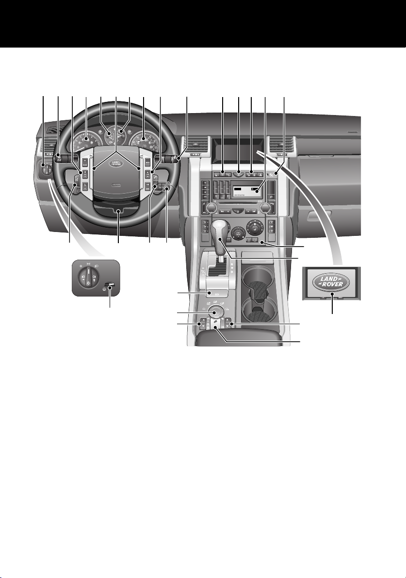
FACIA CONTROLS
Quick Start
1 2 3 4 6 7 8 9
A
U
T
O
27
5
26
AUTO
28
LAN0111N
25
24
23
22
21
10 11
123
456
789
ABC DEF
JKL MNOGHI
TUV WXYZPQRS
0
12 13
CD 3 14 : 54
2Tr 15:43
123456
14
15
6CD-465
16
17
18
19
20
16
Page 17

Quick Start
FACIA CONTROLS KEY
1. Lamps master switch
2. High beam/Direction indicators/Trip
computer
3. Cruise control switches
4. Tachometer
5. Temperature gauge
6. Horn buttons
7. Fuel gauge
8. Speedometer
9. Audio/Telephone remote controls
10. Wiper/washer controls
11. Dynamic Stability Control (DSC) switch
12. Hazard warning lamp switch
13. Door lock/unlock switches
14. Audio display/controls
15. Passenger air bag status indicator
16. Heater/Air conditioning controls
17. Gear selector
18. Display screen
19. Transfer gearbox switch
20. Hill Descent Control (HDC) switch
21. Air suspension switch
22. Terrain Response
23. Electric parkbrake (EPB) switch
24. Starter switch
25. Telephone switch
26. Steering column adjustment
27. Voice recognition switch
28. Dimmer control
TM
control switch
17
Page 18
Quick Start
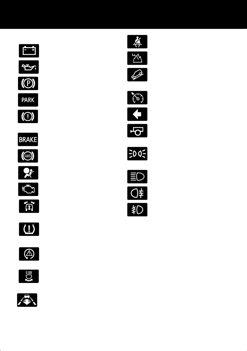
WARNING INDICATORS
Battery charging - RED.
Low oil pressure - RED.
Parkbrake - RED (Canada only).
Parkbrake - RED (U.S. only).
Brakes - RED/AMBER
(Canada only).
Brakes - RED/AMBER (U.S.only).
Anti-lock braking system - AMBER.
Air bag - RED.
Engine - AMBER.
Suspension/Dynamic response RED/AMBER.
Seat belts - RED.
Low gear range selected - GREEN.
Hill Descent Control (HDC) on GREEN.
Cruise control active - AMBER.
Direction indicator - GREEN.
Trailer direction indicator GREEN.
Side lamps/Headlamps on GREEN.
Headlamp high beam on - BLUE.
Rear fog lamps on - AMBER.
Front fog lamps on - GREEN.
Low tire pressure - AMBER.
Dynamic Stability Control (DSC) AMBER.
Adaptive front lighting system AMBER.
Adaptive Cruise Control (ACC) AMBER.
If a red warning indicator illuminates while
driving, a serious fault is indicated. Stop the
vehicle and refer to the main section of this
handbook.
For a full description of warning indicators and
their functions, see Warning Indicators, 100.
18
Page 19
Quick Start
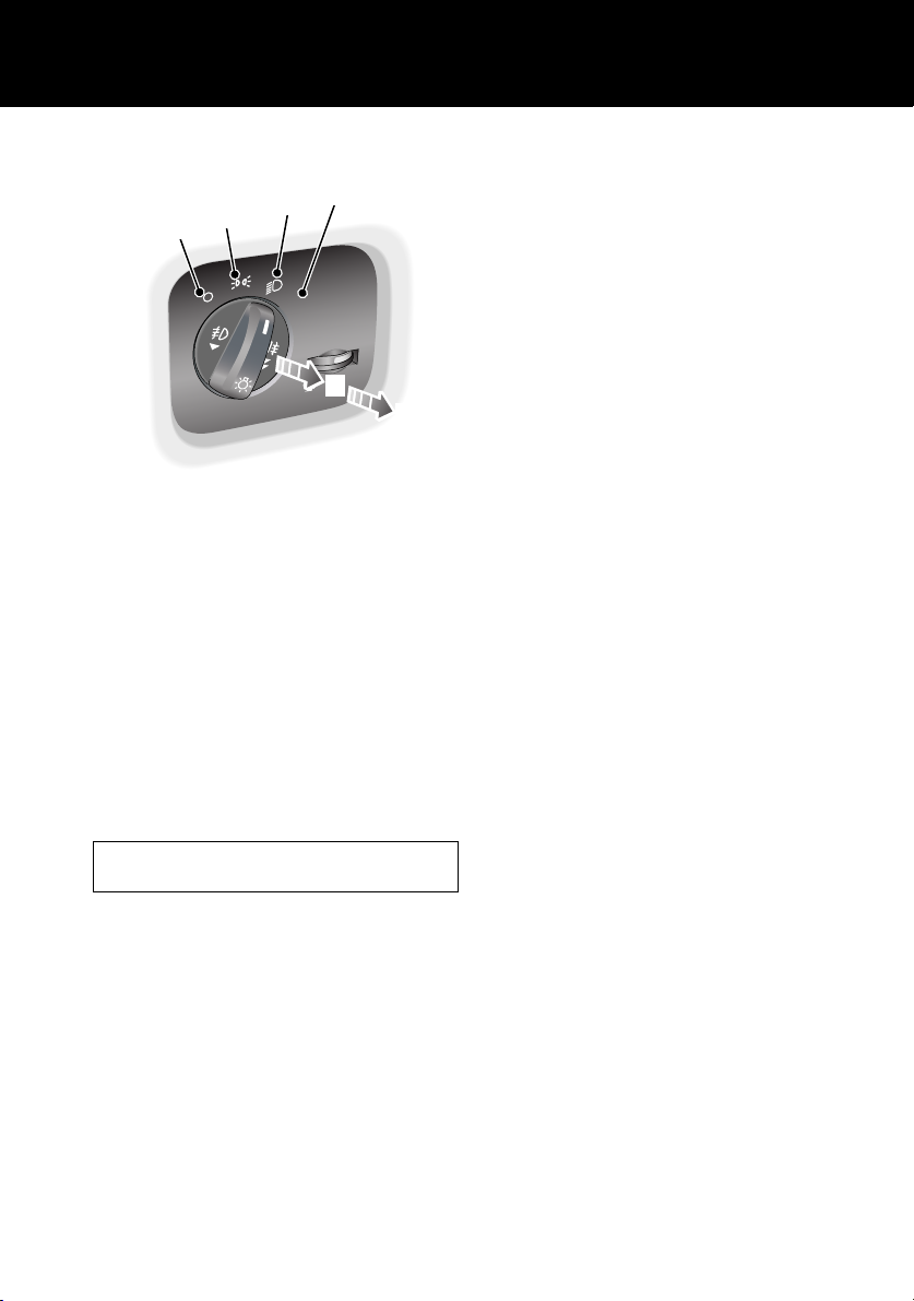
LAMPS MASTER SWITCH
4
3
2
1
O
T
AU
5
LAN0403G
1. Side lamps and headlamps off.
2. Side lamps on.
3. Low beam headlamps on.
4. Automatic control lamps on.
In AUTO mode and the starter switch in
position II, a sensor monitors the exterior
light levels and will automatically switch
the side lamps and low beam headlamps
on or off as required.
5. Front fog lamps on.
6. Front and rear fog lamps on.
Headlamp courtesy delay
With the master switch in positions 2, 3 or 4,
turn the starter switch off and remove the key.
Turn the master switch to the off position. The
headlamps will remain on for up to 240
seconds. For a full description of this feature
and how to set the time delay, see Headlamp
courtesy delay, 43.
6
Fog lamps cannot be operated if the lamps
master switch is at position 4 Auto.
For a full description of these functions, see
EXTERIOR LAMPS, 107.
19
Page 20
Quick Start
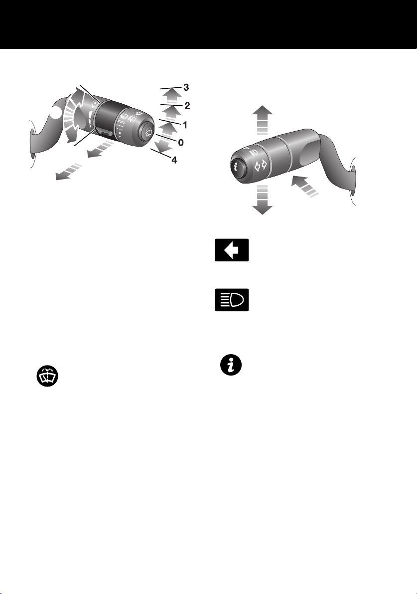
STEERING COLUMN LEVERS
5
6
7
LAN0519G
1. Rain sensor variable delay wipe.
2. Normal speed wipe.
3. Fast speed wipe.
4. Single wipe.
5. Rotate collar to adjust rain sensor variable
delay.
Rear wiper and washer
Pull the lever to position 6 for intermittent
operation of the rear wiper. Pull and hold the
lever in position 7 to operate the rear washer
and wiper.
Windshield washer
Push the button on the end of the
lever to operate the wndscreen
washer.
For more detailed information on the wash/wipe
system, see WINDSHIELD WIPERS, 110.
Direction/turn indicators/Headlamp high
beam
LAN0405G
Move the lever up or down to
activate the direction/turn
indicators.
Push the lever away from you to
select headlamp high beam. A
blue warning indicator will
illuminate on the instument pack.
Trip computer
Press the button on the end of the
lever to cycle through the trip
computer functions displayed on
the message center.
See TRIP COMPUTER -
FUNCTION SELECTION, 85
20
Page 21

Quick Start
CONFIGURABLE FEATURES
Settings options (trip computer)
These are displayed on the main message center. See SELECTING SETTINGS OPTION, 86.
SETTINGS CHOICE
TRIP DISTANCE UNITS (odometer) MILES/KM
FUEL USAGE UNITS MPG
l/100km
Km/l
o
EXTERNAL TEMPERATURE
OVERSPEED WARNING
(Set a personal speed limit - Warnings are
displayed in the message center)
HEADLAMP OFF DELAY 30/60/120/240 seconds
AUTO DOOR LOCK (speed related locking) ON/OFF
REVERSE MIRROR DIP ON/OFF
LAZY ENTRY ON/OFF
RESTORE DEFAULT SETTINGS YES/NO
C or oF
Off
20 - 250 km/h or 15 to 140 mph in 5-unit steps
(units set as trip distance)
Remote control
The remote control can be configured to
operate the following features:
• Panic alarm, for personal protection. See
Panic alarm, 43.
• Headlamp courtesy delay, providing
lighting for personal safety. See Headlamp
courtesy delay, 43.
• Air suspension control, allows remote
operation of the air suspension. See Air
suspension control, 44.
• Tailgate release function, releases the
tailgate as a whole. See Tailgate release,
45.
• Tailglass release function, releases only the
tailglass. See Tailglass release, 45.
• Single point entry, allowing only the drivers
door to be opened remotely. See
Single-point entry, 44.
Daytime running lamps
Unless prevented by legislation, it is possible to
automatically switch on the exterior lamps
whenever the engine is running. See Daytime
running lamps, 108.
Speed dependent wiper mode
The wiper speed in all modes can be
automatically varied according to vehicle
speed. See Speed-dependent mode, 111.
21
Page 22
Quick Start
OVERHEAD CONSOLE
1
2
LAN0401G
Courtesy lamps
If automatic mode is enabled, the front and rear
courtesy lamps will operate in conjunction with
the vehicle being unlocked/locked or when a
door is opened.
Automatic mode
Automatic mode for the courtesy lamps can
be enabled/disabled by pressing and holding
the center lamp switch for more than three
seconds.
A message will be displayed in the message
center advising you of the mode currently set.
Sunroof
Open/close sunroof:
• Press and release the switch 1 to open the
sunroof fully.
• Press the switch 2 to close.
Tilt sunroof:
• Press and release the switch 2 to open the
sunroof to the tilt position.
• Press and hold the switch 1 to close.
If the sunroof is moving, it can be stopped by
pressing the swich again.
See SUNROOF OPERATION, 117.
Operating note
The sunroof can be operated with the starter
key in position I or II and for 40 seconds after
position 0 has been selected, providing that
neither front door has been opened.
With the starter key in position I or 0, the
switch will need to be pressed and held until
the roof reaches the desired position.
The courtesy lamps can be manually switched
on/off by pressing and releasing the center
lamp switch (arrowed in illustration).
See Front interior lamps, 127.
Interior lamps
The interior lamps can be switched on/off by
pressing the switch adjacent to the lamp.
22
Page 23
Quick Start
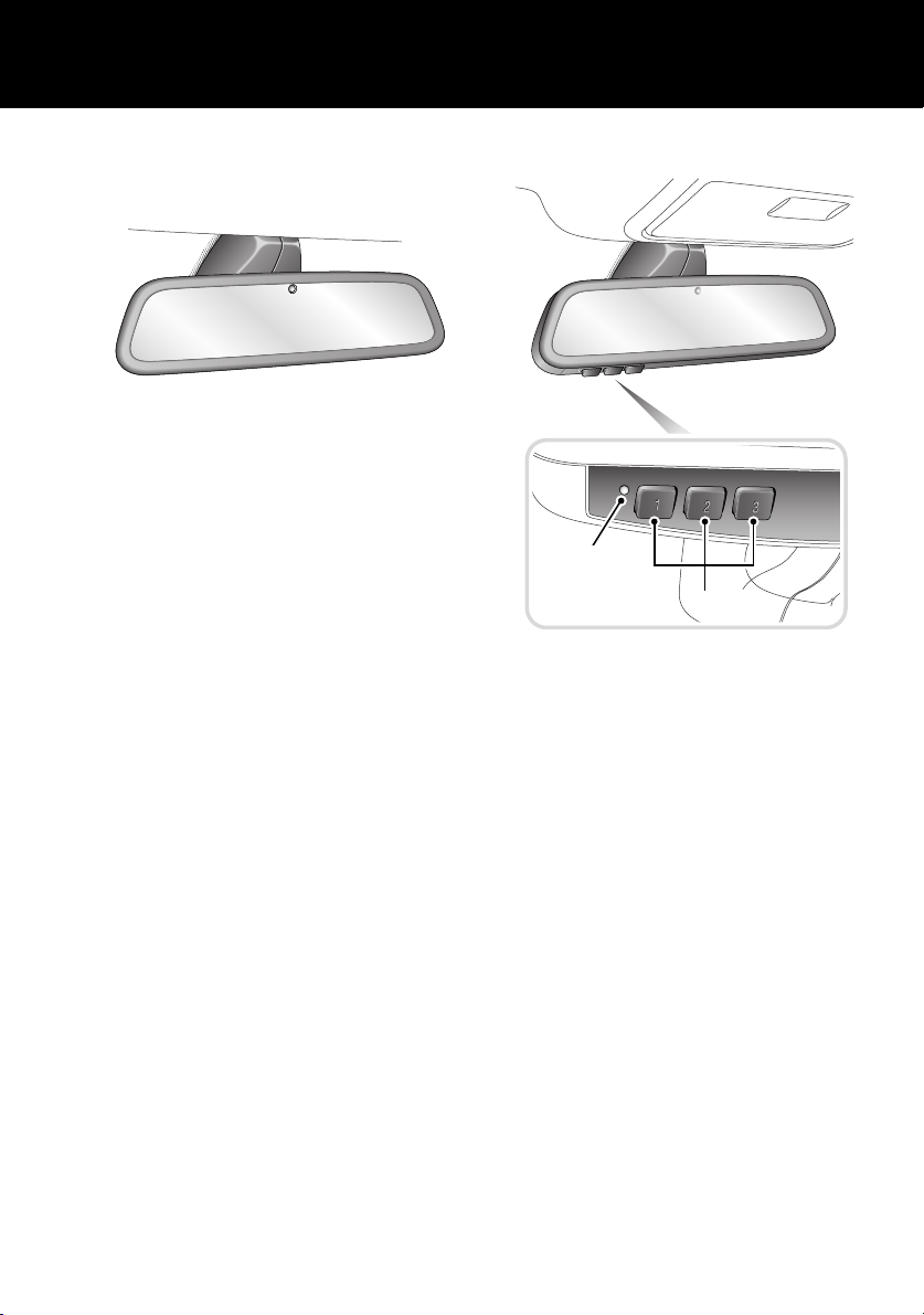
REAR VIEW MIRROR
Automatic dimming
LAN0231G
Rear view mirrors are fitted with a feature that
will automatically darken to counteract glare
from the headlamps of a following vehicle.
This feature is temporarily switched off while
reverse gear is selected.
See REAR-VIEW MIRROR, 133.
HOMELINK® TRANSMITTER
1
2
H6480N
1. Status indicator light
Red - transmitter
Green - auto dimming
2. Channel buttons
The buttons 2 can be programmed to transmit
radio frequencies that can operate external
devices i.e. garage doors, entry gates, security
systems etc.
See HOMELINK® TRANSMITTER, 140.
23
Page 24
Quick Start
AUTOMATIC TRANSMISSION
Gearshift interlock
The starter switch must be in position II, the
foot brake applied and the selector release
button pressed before the gear selector can be
moved from P (Park) to R (Reverse).
The gear selector must be in P before the starter
key can be removed.
See AUTOMATIC TRANSMISSION USE, 157.
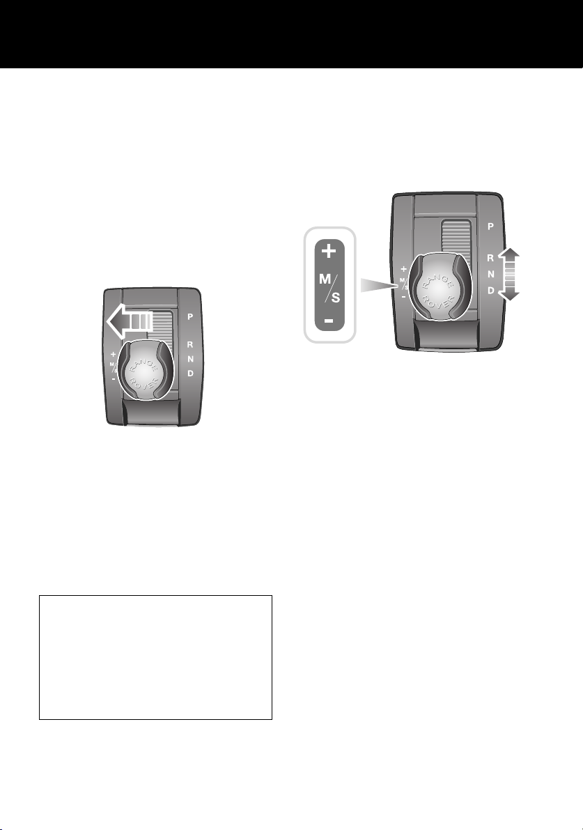
Sport mode
LAN0408G
In Sport mode, automatic gear changing is
maintained but the gearshift changes are
modified to improve performance.
To select Sport mode, move the gear selector
from D towards the left-hand side of the vehicle.
The word SPORT will appear in the instrument
pack display and the LED in the gear selector
surround will illuminate.
With the gear selector in Sport, the
transmission will stay in lower gears for
longer with downshifts occurring more
readily.
Fuel consumption will be adversely affected.
When using Terrain Response, Sport mode is
only available if the General program is
selected.
CommandShift
CommandShift gear selection can be used as
an alternative to automatic gear selection and is
particularly effective when rapid acceleration or
engine braking is required.
LAN0422G
1. Select Sport mode. The transmission will
automatically select the gear most
appropriate to the vehicle’s road speed and
accelerator position.
2. Moving the selector lever forward (+) or
backward (-) and then releasing will
manually select a higher or lower gear
(when available). The message
TRANSMISSION COMMANDSHIFT
SELECTED will appear in the message
center.
3. Subsequent gear selections will shown in
the instrument pack display.
4. To deselect CommandShift mode, move
the selector lever back to D.
24
Page 25
Quick Start
HILL DESCENT CONTROL (HDC)
LAN0263G
HDC operates in conjunction with the anti-lock
braking system to provide greater control in
off-road situations, particularly when
descending severe gradients.
Press the switch (arrowed in
illustration) to select HDC. HDC
can be selected at speeds below
80 km/h (50 mph), but will not be fully active
until the vehicle speed reduces below 50 km/h
(30 mph), confirmed by a continuously
illuminated HDC indicator in the instrument
pack.
Press the switch again to deselect HDC.
See HILL DESCENT CONTROL (HDC), 181.
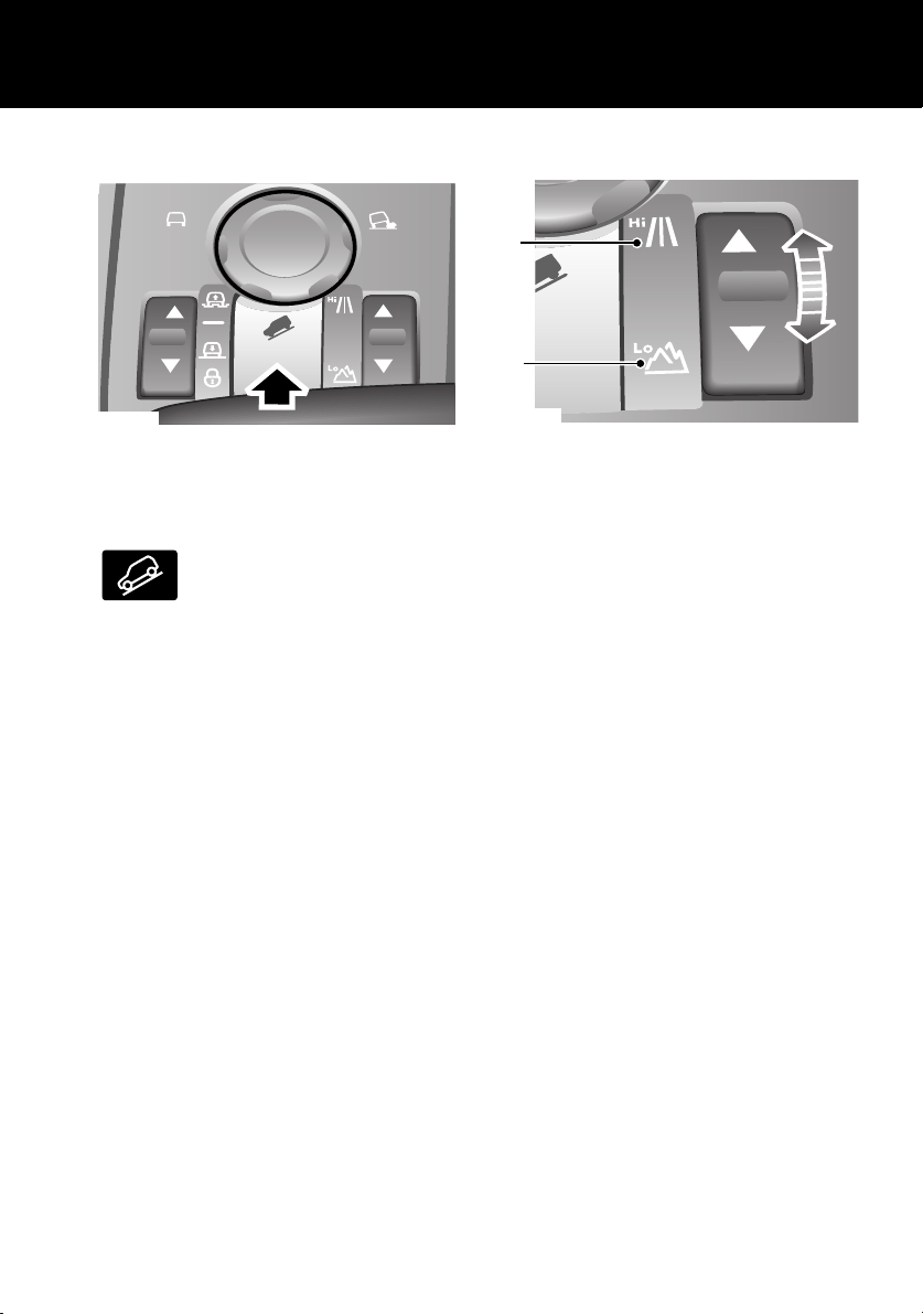
TRANSFER GEARBOX
1
2
LAN0424G
1. HIGH range should be used for all normal
road driving and also for off-road driving
across dry level terrain.
2. LOW range should be used in situations
where low speed manoeuvring is
necessary, or in extreme off-road
conditions.
Range changing
The recommended method for range changing
is with the vehicle stationary. With the engine
running and the main gearbox in N (Neutral),
press and release the front/rear of the transfer
gearbox switch to select the range required.
The indicators on the switch and instrument
pack display will flash during range changing.
When range changing is complete, a chime will
sound and a message displayed in the message
center.
See TRANSFER GEARBOX, 162.
25
Page 26
Quick Start
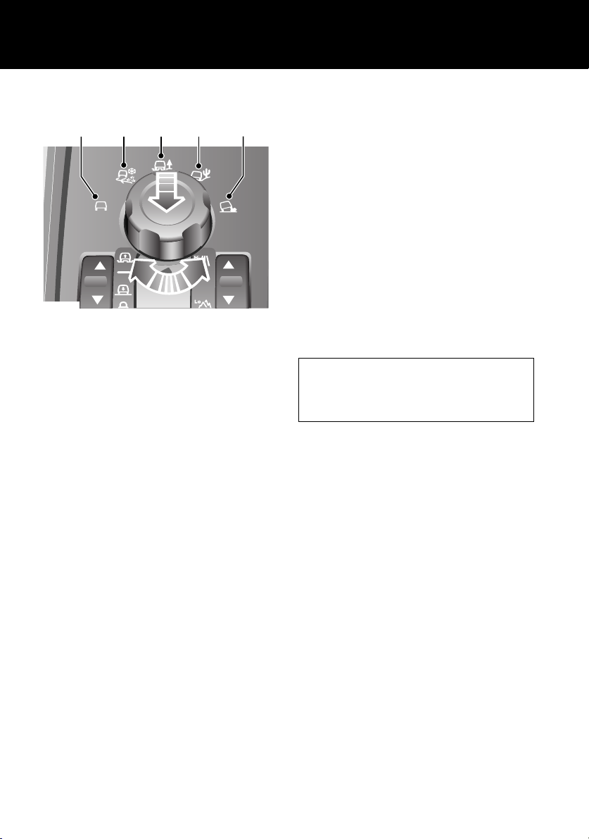
TERRAIN RESPONSE SYSTEM
1
LAN0426G
1. General: Suitable for surfaces that match
typical road surfaces.
2. Grass-Gravel-Snow: Suitable for surfaces
which are firm, but have a slippery surface,
e.g. grass, snow, loose gravel, pebbles or
icy conditions.
3. Mud-Ruts: Suitable for soft, muddy,
uneven or deeply rutted ground. It is
recommended that LOW range is selected
on the Transfer gearbox.
4. Sand: Suitable for soft, predominantly dry,
yielding sandy ground, e.g. sand dunes and
deserts. If the sand is damp or wet, the
Mud-Ruts program may be more
beneficial.
5. Rock Crawl: Only selectable when the
Transfer gearbox is in LOW range. Suitable
for crossing wet or dry, solid unyielding
ground requiring high levels of wheel
displacement, e.g. clusters of boulders or
rocky river beds.
See TERRAIN RESPONSE, 191.
2
4
3
5
The Terrain Response system is always active
and cannot be switched off. When the vehicle is
started, the system will normally start in its
General program.
To raise the rotary knob, press down lightly and
release. Manual selection of a special program,
by rotating the knob, will provide benefits in
how the vehicle can be driven over different
surfaces or terrains by automatically adjusting
the vehicle’s drive and suspension systems.
It is recommended that a special program be
engaged whenever driving conditions could
become difficult and cancelled once the
conditions for use are no longer present. To
lower the rotary knob press down until a ‘click’
is heard.
Wading
When driving through water less than 490
mm (19 inches) deep, select the program
suitable for the surface beneath the water.
26
Page 27
Quick Start
AIR SUSPENSION
2
3
4
1
5
6
LAN0271G
Vehicle height can be manually adjusted via the
raise/lower switch 1. Height changes may only
be made when the the engine is running and the
driver and passenger doors are closed.
Indicators 2 or 7 will illuminate to show the
direction of movement. They extinguish when
the height change is complete.
Off-road height 3, provides improved ground
clearance and approach, departure and
break-over angles.
On-road height 4, is the normal height for the
vehicle.
Access height 5, lowers the vehicle to provide
easier entry, exit and loading of the vehicle. This
position may be selected up to 40 seconds after
the starter switch is turned off.
Crawl (locked at Access height) 6, allows the
vehicle to be driven at low speeds at access
height, to give increased roof clearance.
7
See AIR SUSPENSION, 184.
CRUISE CONTROL
Cruise control enables the driver to maintain a
constant road speed without using the
accelerator pedal.
4
3
2
1
LAN0252G
1. CANCEL: cancel cruise control, but retains
the set speed in memory.
2. RESUME: resumes a SET speed retained in
memory.
3. SET - : to set a road speed or decrease the
speed in 2 km/h (1 mph) steps when cruise
control is operating.
4. SET + : to set a road speed or increase the
speed in 2 km/h (1 mph) steps when cruise
control is operating.
Cruise control will automatically disengage
when the brake pedal is used or when the
vehicle speed falls below 30 km/h (18 mph).
See CRUISE CONTROL, 165.
Vehicle height will be automatically adjusted
according to road speed in order to maintain
driveability and handling.
If Terrain Response is fitted, some of its
programs will automatically adjust the
suspension height.
27
Page 28
Quick Start
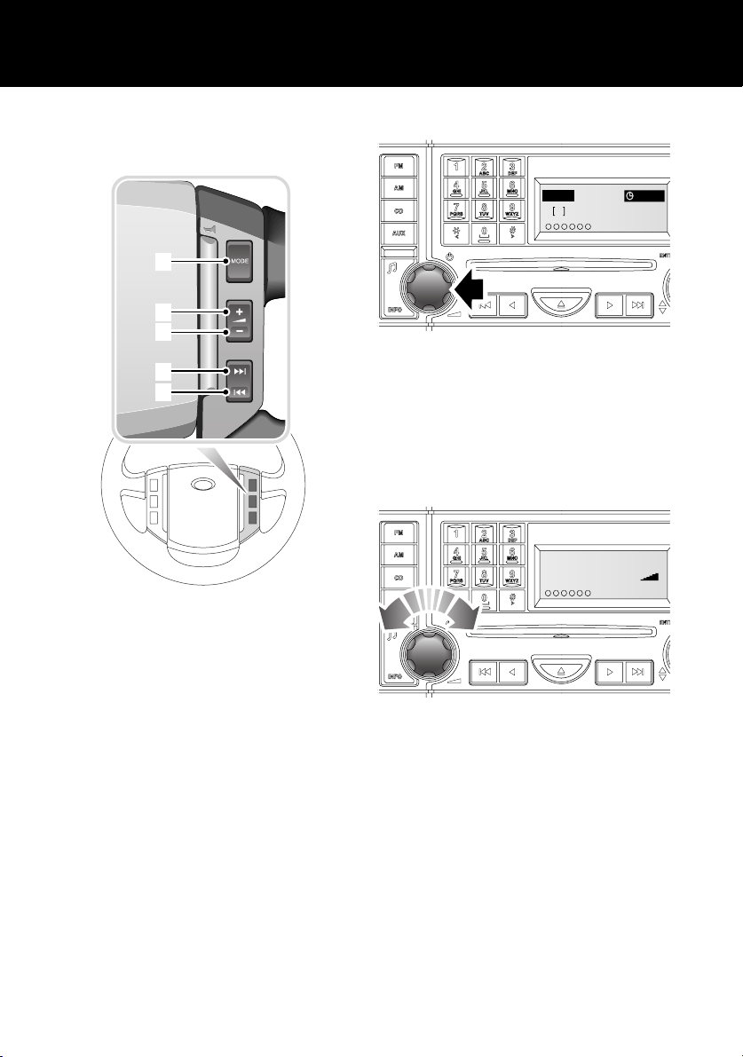
AUDIO SYSTEM OPERATION
Steering wheel controls
1
2
3
4
5
ICE1579 ENG
1. Mode select
2. Volume up
3. Volume down
4. Channel up
5. Channel down
Switching on the audio unit
FM 14 : 54
2
107.9
123456
ICE1911 NAS
KSAN FM
To turn on the audio unit, press the rotary
control.
To make any of the changes to settings, as
shown in the following pages, the unit must be
switched on.
Volume control
Audio Volume
16
123456
ICE1615 ENG
ICE 1615
To increase or decrease the volume level, rotate
the control.
With the engine running, the volume level can
be adjusted between 0 and 35. If the audio unit
is turned off, it will re-start at the previously
selected volume level, provided that this is not
too loud or too quiet.
28
Page 29
Quick Start
I
Tone and balance settings
Bass
123456
ICE1618 ENG
To change the Bass, Treble, Balance, Fader,
Subwoofer and Logic 7 settings, press the Tone
button (arrowed) repeatedly until the required
setting is displayed, then use the rotary control
to adjust the setting as required.
For further information, see TONE AND
BALANCE ADJUSTMENT, 299.
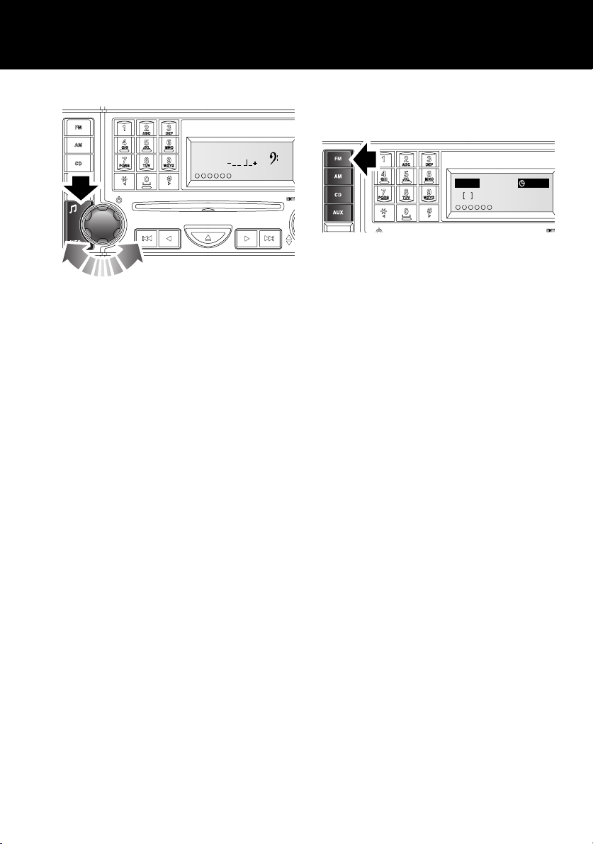
RADIO OPERATION
Autostore
FMA 14 : 54
106.5
2
123456
CE2135 NAS
To autostore FM or AM stations, press and hold
the FM or AM buttons. Autostore will be shown
in the information display and the stations will
be stored under the pre-set numbers, in the
order that they are found.
To access the stations once stored, press the
required pre-set number briefly.
Autostore
29
Page 30
Quick Start
789
TUV WXYZPQRS
0
CD OPERATION
Inserting a CD
123
ABC DEF
456
JKL MNOGHI
CD 14 : 54
No Discs
Press 1-6
CD 3 14 : 54
Please Wait
CD 3 14 : 54
Disc
Insert
When inserting a disc into either player, ensure
that the label side of the disc is facing upwards
and present the disc to the slot. Do not push it
into the slot, the player mechanism will draw
the disc in automatically.
There will be a short pause whilst the player
reads the information from the disc, which will
then be displayed on the screen. Play will
commence at the first track on the newly
inserted disc.
Dual and DVDPlus discs
Please be aware that a new generation of DVD
discs is being adopted by the music industry.
They are known as Dual Discs or DVDPlus
discs. They have digital music on one side and
video content on the other. Current in-car audio
systems with a front loading CD player may
load and play this type of disc, however, it is
likely that the disc will not eject and will block
up the player. Such damage to a CD player will
not be covered under warranty.
ICE1875 ENG
Before inserting a CD into the audio unit, select
CD mode by pressing the CD button.
Note: It is necessary to then select an empty CD
slot, by pressing the appropriate disc selection
button (e.g. 3). The six circles at the bottom
left-hand side of the screen represent the six
available CD slots. As soon as one has a CD in
it, its number will appear in the circle. Empty
slots are, therefore, those without numbers.
30
Page 31

Quick Start
789
TUV WXYZPQRS
0
CD playback To start CD playback, briefly press the CD mode
button, followed by the disc number required. If
no disc number is selected, playback will begin
at one of two places:
• If the discs contained in the player have not
been removed since their last use, playback
will begin from the point at which it was
stopped previously.
• If the discs contained in the player have not
been used since they were inserted,
playback will begin at the start of disc one.
If a CD is already inserted but the audio system
is currently in radio mode, press the CD mode
button to commence playback.
123
ABC DEF
456
JKL MNOGHI
123 564
CD 3 14 : 54
01
3
12 456
3
ICE1887 ENG
CD 1 14 : 54
3Tr
12:15
123 56
4
CD 3 14 : 54
Loading
6CD-465
:
0Tr
01
31
Page 32

Quick Start
VOICE RECOGNITION
Activating the system
LAN0237G
To activate voice control:
• Briefly pull the control paddle (the Audio
will mute at this point). A beep will be
heard, and LISTENING will be displayed on
the main message center to indicate that
the system is now waiting for a voice
command.
Note: It is only necessary to use the steering
wheel voice control paddle at the beginning of
each voice session.
Defined voice commands
The voice control system understands
predefined commands which need to be quoted
word for word.
An audio feedback of voice commands is
available. To activate the feedback, pull the
voice control paddle briefly and give one of the
following commands:
General commands
• Voice help - To list all commands.
• Notepad Help - To list Notepad
commands.
Audio commands
• Radio help - To list Radio commands.
• CD help - To list CD commands.
See Audio System, 293, for full operating
instructions.
Navigation and Telephone commands
• Phone help - To list telephone commands.
• Navigation help - To list Navigation
commands.
Please refer to the Navigation and
Telephone Handbook for full operating
instructions.
For further information, see VOICE
RECOGNITION, 138.
32
Page 33

Gas Station Information
Gas Station Informat ion
FUEL FILLER
Note: The fuel filler flap has a spring loaded
release, do not force it open.
The fuel filler is located in the rear right-hand
When delivery is complete, withdraw the nozzle
and replace the cap. Tighten the cap clockwise
until you hear it click three times. Return the
fuel filler flap to the closed position.
fender. Press and release the center of the left
edge of the fuel filler flap to open. See arrow
1
position 1.
The fuel filler flap springs out, revealing the
filler cap 2.
2
Unscrew the filler cap and place it on the
projection on top of the hinge of the fuel filler
flap.
Insert the pump nozzle into the filler neck,
pushing aside the spring-loaded cover.
LAN0438G
Note: For more detailed information, see FUEL
FILLER, 151.
Fuel type
V8 engines Premium unleaded gasoline with a CLC or AKI octane rating of 91
or higher. See TYPE OF FUEL, 153.
Note: Mid or regular grade gasoline with a CLC or AKI octane rating
of not lower than 87 may also be used, but performance and fuel
economy will be reduced.
Engine oil top-up
V8 vehicles Use only oils certified for gasoline engines by the American
Petroleum Institute (API). Use a 5W/30 oil meeting specification
API SM+ILSAC GF4.
Cooling system top-up
All vehicles to -40°C (-40°F) 50% mix of water and an approved antifreeze
Note: For more detailed information, see LUBRICANTS AND FLUIDS, 287.
LAND ROVER RECOMMENDS
33
Page 34

Gas Station Information
TIRE PRESSURES
Air pressure naturally increases in warm tires
(after the vehicle has been driven for a while). If
you have to check warm tires, you should
expect the pressures to have increased by
between 30 and 40 kPa (4 to 6 lb/in
circumstance, NEVER let air out of the tires in
order to match the recommended pressures.
See Checking tire pressures, 234
2
). In this
34
Page 35

General Information
General Information
SYMBOLS GLOSSARY
The following warnings, cautions and symbols
used within the handbook call your attention to
specific types of information.
Warnings
WARNING
Safety warnings are included in this
handbook. These indicate either a procedure
which must be followed precisely, or
information that should be considered with
great care in order to avoid the possibility of
personal injury.
Cautions
Caution: Cautions are included in this
handbook. These indicate either a procedure
which must be followed precisely, or
information that should be considered with
great care in order to avoid the possibility of
damage to your vehicle.
Symbols
This recycling symbol identifies those
items that must be disposed of safely in
order to prevent unnecessary damage
to the environment.
This symbol identifies those features
that can be adjusted or disabled/enabled
by a Land Rover Dealer.
WARNING LABELS ATTACHED
TO THE VEHICLE
Warning labels attached to your
vehicle bearing this symbol mean: DO
NOT touch or adjust components until
you have read the relevant
instructions in the handbook.
Labels showing this symbol indicate
that the ignition system utilises very
high voltages. DO NOT touch any
ignition components while the ignition
is turned on.
Warning labels
Labels are attached to your vehicle at several
positions. These are applied to draw your
attention to important subjects, e.g. tire
pressures, tow bar use, air bags, roll-over risk,
engine compartment hazards, etc.
MFD BY LANDROVER IN THE UK
DATE : MM/YY
GVWR: XXXXKG (XXXXLB)
GAWR FRONT: XXXXKG (XXXXLB)
XXX/XXRXX TIRES, X.XJXXX RIMS, AT XXXKPA (XXPSI) COLD
XXX/XXRXX TIRES, X.XJXXX RIMS, AT XXXKPA (XXPSI) COLD
XXX/XXRXX TIRES, X.XJXXX RIMS, AT XXXKPA (XXPSI) COLD
XXX/XXRXX TIRES, X.XJXXX RIMS, AT XXXKPA (XXPSI) COLD
XXX/XXRXX TIRES, X.XJXXX RIMS, AT XXXKPA (XXPSI) COLD
XXX/XXRXX TIRES, X.XJXXX RIMS, AT XXXKPA (XXPSI) COLD
TXXX/XXRXX TIRES, X.XJXXX RIM, AT XXKPA (XXPSI) COLD
GAWR REAR: XXXXKG (XXXXLB)
XXX/XXRXX TIRES, X.XJXXX RIMS, AT XXXKPA (XXPSI) COLD
XXX/XXRXX TIRES, X.XJXXX RIMS, AT XXXKPA (XXPSI) COLD
XXX/XXRXX TIRES, X.XJXXX RIMS, AT XXXKPA (XXPSI) COLD
XXX/XXRXX TIRES, X.XJXXX RIMS, AT XXXKPA (XXPSI) COLD
XXX/XXRXX TIRES, X.XJXXX RIMS, AT XXXKPA (XXPSI) COLD
XXX/XXRXX TIRES, X.XJXXX RIMS, AT XXXKPA (XXPSI) COLD
TXXX/XXRXX TIRES, X.XJXXX RIM, AT XXKPA (XXPSI) COLD
THIS VEHICLE CONFORMS TO ALL APPLICABLE
U.S.FEDERAL MOTOR VEHICLE SAFETY
STANDARDS IN EFFECT ON THE DATE OF
MANUFACTURE SHOWN ABOVE
TESTMARK1234567890
TYPE : MULTI - PURPOSE PASSENGER VEHICLE
35
TIRE AND LOADING INFORMATION
SEATING CAPACITY
The combined weight of occupants and cargo should never exceed XXXkg or XXXXlbs
TIRE COLD TIRE INFLATION PRESSURE
SIZE
XXX/XXRXX
FRONT
XXX/XXRXX
REAR
TXXX/XXRXX
SPARE
LAN0166N
FRONT 2 REAR 3
TOTAL 5
XXPSI XXXkpa
XXPSI XXXkpa
XXPSI XXXkpa
SEE OWNER'S
MANUAL FOR
ADDITIONAL
INFORMATION
Example
RTC500490
Page 36

General Information
It is important that you are familiar with these
subjects to ensure that your vehicle and its
features are used safely. Using the index at the
back of this handbook, refer to the relevant
topic for more information.
WARNING
Your vehicle has a higher ground clearance
and hence, a higher center of gravity than
ordinary passenger cars, to enable the
vehicle to perform in a wide variety of off-road
applications. An advantage of the higher
ground clearance is a better view of the road
allowing you to anticipate problems.
The vehicle is not designed for cornering at
the same speed as conventional passenger
cars any more than a low-slung sports car is
designed to perform satisfactorily under
off-road conditions. If at all possible, avoid
sharp turns or abrupt manoeuvers. As with
other vehicles of this type, failure to operate
the vehicle correctly may result in loss of
control or vehicle roll-over.
DATA RECORDING
Service data recording
Service data recorders in your vehicle are
capable of collecting and storing diagnostic
information about your vehicle. This potentially
includes information about the performance or
status of various systems and modules in the
vehicle, such as engine, accelerator, steering or
brakes.
In order to properly diagnose and service your
vehicle, Land Rover and service and repair
facilities may access vehicle diagnostic
information through a direct connection to your
vehicle.
Event data recording
Event data recorders are capable of collecting
and storing data during a crash or near-crash
event. The recorded information may assist in
the investigation of such an event. The modules
may record information about both the vehicle
and the occupants, potentially including
information such as:
• How various systems in your vehicle were
operating.
• Whether or not the driver and passenger
seat belts were buckled.
• How far, if at all, the driver was depressing
the accelerator and/or the brake pedal.
• How fast the vehicle was travelling.
• Where the driver was positioning the
steering wheel.
To access this information special equipment
must be connected directly to the recording
modules. Land Rover do not access event data
recorder information without obtaining
consent, unless pursuant to court order or
where required by law enforcement, other
government authorities or third parties acting
with lawful authority.
Other parties may seek to access the
information independently of Land Rover.
36
Page 37

General Information
CALIFORNIA PROPOSITION 65
WARNING
WARNING
Engine exhaust, some of its constituents and
certain vehicle components contain or emit
chemicals known to the State of California to
cause cancer and birth defects or other
reproductive harm. In addition, certain fluids
contained in vehicles and certain products of
components wear contain or emit chemicals
known to the State of California to cause
cancer and birth defects or other reproductive
harm.
WARNING
Battery posts, terminals and related
accessories contain lead and lead
compounds. Wash hands after handling.
37
Page 38

Reporting Safety Defects
Reporting Safety Defects
REPORTING SAFETY DEFECTS
(U.S. ONLY)
If you believe that your vehicle has a defect
which could cause a crash, or could cause
injury or death, you should immediately inform
the National Highway Traffic Safety
Administration (NHTSA) in addition to notifying
Land Rover North America Inc.
If NHTSA receives similar complaints, it may
open an investigation and if it finds that a safety
defect exists in a group of vehicles, it may order
a recall and remedy campaign.
However, NHTSA cannot become involved in
individual problems between you, your Dealer
or Land Rover North America Inc.
To contact NHTSA, you may call the Vehicle
Safety Hotline toll-free at 1-888-327-4236
(TTY: 1-800-424-9153); go to
http://www.safecar.gov; or write to:
Administrator,
NHTSA,
400 Seventh Street SW.,
Washington, DC 20590.
You can also obtain other information about
motor vehicle safety from
http://www.safecar.gov.
REPORTING SAFETY DEFECTS
(CANADA ONLY)
If you believe that your vehicle has a defect
which could cause a crash, or could cause
injury or death, you should immediately inform
Transport Canada in addition to notifying Land
Rover Canada.
To contact Transport Canada, call their toll-free
number: 1-800-333-0510.
38
Page 39

Parts and Accessories
Parts and Accessories
PARTS AND ACCESSORIES
WARNING
The fitting of non-approved parts and
accessories, or the carrying out of
non-approved alterations or conversions,
may be dangerous and could affect the safety
of the vehicle and occupants and also
invalidate the terms and conditions of the
vehicle warranty.
Land Rover will not accept any liability for
death, personal injury or damage to property
which may occur as a direct result of fitment
of non-approved accessories or the carrying
out of non-approved conversions to Land
Rover vehicles.
Land Rover strongly advise against making
any modifications to the suspension or
steering system. This could seriously affect
the handling and stability of the vehicle
leading to loss of control or roll-over.
The vehicle has been designed, built and tested
to cope with a variety of off-road driving
conditions, some of which can place the
severest possible demands on control systems
and components. As such, fitting replacement
parts and accessories that have been developed
and tested to the same stringent standards as
the original components will safeguard the
continued reliability, safety and performance of
the vehicle.
To augment the vehicle's already impressive
performance, a comprehensive range of Land
Rover approved spare parts and accessories is
available, enabling the vehicle to fulfil a wide
variety of roles, and enhancing and protecting
the vehicle in the many tasks to which it can be
applied.
Land Rover parts are the only parts built to
original equipment specifications AND
approved by Land Rover designers; this means
that every single part and accessory has been
rigorously tested by the same engineering team
that designed and built the vehicle and can
therefore be guaranteed for twelve months with
unlimited mileage.
A full list and description of all accessories is
available from Land Rover Dealer.
Electrical equipment
WARNING
It is extremely hazardous to fit or replace
parts or accessories, the installation of which
requires the dismantling of, or addition to,
either the electrical or fuel systems.
ALWAYS consult a Land Rover Dealer before
fitting any accessory.
Fitting inferior quality parts or accessories, may
be dangerous and could invalidate the vehicle
warranty.
It is recommended that you always consult a
Land Rover Dealer for advice regarding the
approval, suitability, installation and use of any
parts or accessories before fitting.
In certain countries, it is illegal to fit parts which
have not been made to the vehicle
manufacturers' specification.
Owners should ensure that any parts or
accessories fitted to the vehicle while travelling
abroad will also conform to the legal
requirements of their own country when they
return home.
39
Page 40

Parts and Accessories
SRS/Air bag
WARNING
The components that make up the SRS/air bag
are sensitive to electrical or physical
interference, either of which could easily
damage the system and cause inadvertent
operation or a malfunction of the air bag
module.
To prevent any SRS/air bag malfunction,
ALWAYS consult a Land Rover Dealer before
fitting any of the following:
• Electronic equipment such as a mobile
phone, two-way radio or in-car
entertainment system.
• Accessories attached to the front of the
vehicle.
• Any modification to the front of the
vehicle.
• Any modification involving the removal or
repair of any wiring or component in the
vicinity of any of the SRS components
(yellow wiring harness), including: the
steering wheel, steering column,
instrument and facia panels.
• Any modification to the facia panels or
steering wheel.
40
Page 41

Keys and Remote Controls
Controls and Instruments
KEYS AND REMOTE CONTROLS
Caution: Keep the spare remote control in a
safe place - NOT IN THE VEHICLE.
LAN0112G
You have been supplied with two remote
controls with integral keys which operate all of
the vehicle’s locks.
The operation of all buttons, on remote
controls, will be inhibited whilst a key is in the
starter switch.
Note: The remote control may not operate
correctly in areas that are subject to
interference from other radio equipment
operating on a similar frequency. Areas where,
for example, equipment such as amateur radio,
medical devices, telecommunications
equipment or other remotely operated alarms
are in use may cause difficulty. If such
difficulties are experienced, try to operate the
remote control as close as possible to the
vehicle, or use the key in the door lock. See
Emergency locking/unlocking, 50.
The remote controls supplied with your vehicle
are programmed to your security system - the
engine cannot be started without a remote
control programmed to your vehicle.
Note: Should a remote control be lost or
damaged, a replacement can only be obtained
from your Land Rover Dealer, where it will be
programmed to your vehicle. The Dealer will
require proof of ownership, and keep a log of all
enquiries for replacement remote controls.
It is advisable to notify your Dealer as soon as
possible if a remote control is lost or stolen,
and have the remaining remote control
reprogrammed. This will prevent access to the
vehicle using the lost/stolen remote control.
Compliance
The remote control complies with part 15 of the
FCC rules. Operation is subject to the following
conditions:
• This device may not cause harmful
interference.
• This device must accept any interference
received, including interference that may
cause undesired operation.
Any changes or modifications to the remote
control not expressly approved by the
manufacturer or Land Rover North America Inc.
could void the user’s authority to operate the
equipment.
Transmitter FCC ID: NT8-15K6014CFFTXA
Receiver FCC ID: LQN5752
41
Page 42

Keys and Remote Controls
Remote control battery
Caution: The remote control contains delicate
electronic circuits and must be protected from
impact and water damage, high temperatures
and humidity, direct sunlight and the effects
of solvents, waxes and abrasive cleaners.
The battery is rechargeable. The fact that the
battery needs recharging will be apparent from
the following:
• KEY BATTERY LOW will be displayed in the
main message center.
• A gradual deterioration in range and
performance will be noticed.
Battery recharge
Insert the key into the starter switch and start
the engine. This will start to recharge the
remote control battery.
Vehicle security
For your own safety, and that of the vehicle,
when the vehicle is left unattended you should:
• Apply the parkbrake.
• Remove all keys and remote controls from
the vehicle prior to locking the doors.
• Close all doors, windows, luggage
compartment (including blind), sunroof,
and glovebox.
• Park the vehicle where it is visible (a well lit
area after dark).
• Keep your vehicle’s keys safely out of sight.
• NEVER leave children or pets unattended in
the vehicle.
• NEVER leave luggage or valuables on
display.
LAND ROVER BUTTON
Customer programmable button
WARNING
Be aware that the previously programmed
feature will be activated when the button is
initially pressed to start the programming
sequence.
LAN0128G
The fourth button - marked with the Land Rover
logo - on the remote control can be
programmed to give remote operation of one of
the following functions:
• panic alarm
• headlamp courtesy delay
• air suspension control
• tailgate release
• tailglass release
Note: Programming and subsequent use of the
Land Rover button will not occur if the key is in
the starter switch.
42
Page 43

Keys and Remote Controls
REMOTE CONTROL PROGRAMMING
Panic alarm
23
LAN0118G
Programme by keeping the Land Rover button
pressed and also pressing the hazard warning
lamps button on the instrument panel. A chime
from the instrument panel will confirm
successful programming.
A short press of the Land Rover button will now
cause the vehicle’s alarm to be sounded and the
hazard warning lamps to flash.
The alarm is turned off by pressing the lock or
unlock buttons on the remote control or
inserting the key in the starter switch.
Headlamp courtesy delay
LAN0119G
Programme by keeping the Land Rover button
pressed and also flashing the headlamps. A
chime from the instrument panel will confirm
successful programming.
A short press of the Land Rover button will now
cause the vehicle’s headlamps to illuminate for
the length of time specified in Settings.
See SELECTING SETTINGS OPTION, 86.
A second press of the button after three
seconds will deactivate the lamps. A further
press, within three seconds, will activate the
reverse lamps. A further press will deactivate
the headlamps and reverse lamps.
43
Page 44

Keys and Remote Controls
Air suspension control
LAN0120G
Programme by keeping the Land Rover button
pressed and also pressing the suspension
control switch. A chime from the instrument
panel will confirm successful programming.
Programming of this function must be done
within one minute of switching off the engine.
After programming, to change the suspension
height via the remote control, remove the
starter key, turn on the hazard warning lamps
and close all the doors. Remote operation is not
possible unless this is done.
To raise the vehicle, press and hold the Land
Rover button and Lock button.
To lower the vehicle, press and hold the Land
Rover button and Unlock button.
If any button is released during the raising or
lowering of the suspension, all movement of
the suspension will stop. It will restart once the
buttons are pressed again.
The height will initially change slowly but, after
three seconds, the speed will increase. While
the height is changing, a symbol on the
raise/lower switch will be lit according to the
direction of movement.
See Adjusting suspension heights, 185.
If the starting height is above or below On-road
height, movement will stop when On-road
height is reached. Further movement can be
achieved by releasing the buttons and pressing
them again. See AIR SUSPENSION, 184.
Single-point entry
This is a personal security feature, which
enables only the driver's door to be unlocked,
leaving the other doors in a locked state.
Single-point entry can be disabled on individual
remote controls by pressing and holding the
lock and unlock buttons together for three
seconds.
All doors will now unlock with a single press.
Repeating the procedure will re-enable single
point entry.
Each time single-point entry is enabled or
disabled, the vehicle will lock then unlock into
the selected mode.
44
Page 45

Keys and Remote Controls
Tailgate release
LAN0125G
Programme by keeping the Land Rover button
pressed and also pressing the main tailgate
release button on the rear tailgate.
A short press of the button will now cause the
vehicle’s tailgate to release.
Tailglass release
LAN0124G
Programme by keeping the Land Rover button
pressed and also pressing the main tailglass
release button situated under the rear license
plate plinth.
A short press of the button will now cause the
vehicle’s tailglass to release.
45
Page 46

Locks and Alarms
Locks and Alarms
ALARM SYSTEM
LAN0113G
Your vehicle is fitted with a sophisticated
electronic anti-theft alarm and engine
immobilisation system. There are also a
number of additional security features, some of
which are selectable options and some are
standard features of the vehicle.
In order to ensure maximum security and
operating convenience, you are strongly
advised to gain a full understanding of the
features and alternatives available, by
thoroughly reading this section of the
handbook.
Anti-theft alarm indicator
LAN0729G
The indicator provides information about the
status of the alarm and immobiliser systems, as
follows:
When the alarm is armed:
The indicator will double flash for 10 seconds,
then continue to single flash until the vehicle is
disarmed and remobilised.
When the alarm is disarmed but the vehicle is
immobilised (key out of starter switch):
The indicator will single flash until the alarm is
armed or the vehicle is remobilised.
When the alarm is disarmed and the vehicle
is mobilised (key in starter switch):
The indicator gives a one-second flash.
46
Page 47

Locks and Alarms
If the alarm sounds
If the alarm is triggered, the alarm will sound
and the hazard warning lamps will flash for 30
seconds, before resetting to the same
protection status that existed prior to the alarm
being triggered.
To silence the alarm, press the lock or unlock
button on the remote control or insert the key
into the starter switch. Pressing the lock button
will keep the alarm armed.
When the vehicle is disarmed, the hazard
warning lamps will quickly flash eight times if
the alarm has sounded since the vehicle was
last armed.
Perimetric alarm
This feature is activated automatically
whenever the vehicle is locked using the remote
control and protects the doors, hood and
tailgate.
If any of these apertures are opened, or a key
that has not been programmed to the vehicle is
inserted into the starter switch, while the
feature is activated, the alarm will be triggered.
When the perimetric alarm is activated the
direction/turn indicators will flash three times,
and the anti-theft alarm indicator will flash.
Mislock
If an aperture is open when an attempt is made
to lock the vehicle an audible warning will
sound once to indicate that the vehicle is not
secure.
47
Page 48

Locks and Alarms
ENGINE IMMOBILISATION
Engine immobilisation is an important aspect of
the security system. It is designed to safeguard
the vehicle from theft, should the driver forget
to lock the doors. The system prevents the
engine from being started unless the GENUINE
remote control key is inserted into the starter
switch.
Engine immobilisation is automatic five
seconds after the key is removed from the
starter switch.
Note: The engine will be re-mobilised
automatically whenever the genuine remote
control key is inserted into the starter
switch.When this happens, the anti-theft alarm
indicator will illuminate for one second and
then extinguish.
Caution: The immobiliser may suffer
interference from other legal users of this
frequency band.
The immobiliser system operates on a
frequency subject to USA Federal
Communications Commission (FCC) rules. The
device complies with Part 15 of the FCC rules
and RSS-210 of the industry Canada.
Operation is subject to the two following
conditions:
1. The device may not cause harmful
interference.
2. This device must accept any interference
received, including interference that may
cause undesired operation.
The immobiliser frequency approval numbers
for the USA and Canada are shown below:
USA - TTRT5SJB.
Canada - IC: 6276A-T5SJBR1
Note: Note: The manufacturer is not
responsible for any radio interference or TV
interference caused by unauthorized
modifications to this equipment. Changes or
modifications not expressly approved by the
party responsible for compliance could void the
user's authority to operate the equipment.
48
Page 49

Locks and Alarms
LOCKING/UNLOCKING
While it is not necessary to point the remote
control at the vehicle, the remote control must
be within range of the vehicle when a button is
pressed.
Note: If the remote control fails to work even
when close to the vehicle, it could be that it is
not synchronised with the system. See
Emergency locking/unlocking, 50. Putting the
key in the starter switch and running the engine
for six minutes will restore full operation.
The operating range may vary depending upon
remote control battery condition and may
sometimes be limited by physical and
geographical factors beyond your control.
Note: If a key is in the starter switch, the vehicle
will not respond to remote control commands.
Locking with the remote control
Remove the key from the starter switch and
shut all doors, the hood and the tailgate.
1
The four buttons on the remote control are used
as follows:
1. Key release button.
2. Lock button: Press to lock all doors and to
activate the perimetric alarm.
The direction/turn indicator lamps will flash
three times.
3. Unlock button: Press once to disarm the
alarm and unlock the driver’s door and to
activate the Lazy entry feature. See Lazy
entry, 58. Press again to unlock the
remaining doors.
See Single-point entry, 44.
In either case, the interior lamps illuminate
and the direction/turn indicators flash
once.
The hazard warning lamps will quickly flash
eight times when the vehicle is disarmed if
the alarm has sounded since the vehicle
was last armed.
4. Customer Configuration - Land Rover
button: This button can be configured to
operate panic alarm, headlamp courtesy
delay, tailgate release, tailglass release or
suspension control.
See LAND ROVER BUTTON, 42.
LAN0114G
2
3
4
49
Page 50

Locks and Alarms
Partial arming
If an aperture (door, hood or tailgate) is not
fully closed when the remote control lock
button is pressed, the horn will sound briefly to
signal that an aperture is still open. The alarm
will remain disarmed and all of the closed
apertures will lock.
As soon as the open aperture is closed, the
system will automatically arm, signalled by
three flashes of the hazard warning lamps.
Emergency locking/unlocking
Under a removable cap on the left front door
outer handle, there is an emergency-use door
lock.
Removing the cap
LAN0116G
1. Insert the key fully into the slot under the
handle cap.
2. The cap can now be removed at the forward
edge and unhooked from the rear edge.
3. Remove the key from the slot and use it in
the emergency lock.
Locking
Turn the key clockwise to lock only the local
door. To lock all of the doors press the master
lock switch, then exit the vehicle through the
front left door. Lock the left front door by
turning the key clockwise (this will not arm the
alarm system).
50
Page 51

Locks and Alarms
Unlocking
Turn the key in the left front door lock
counter-clockwise to unlock only the local
door.
If the alarm system is not armed, turn the key
counter-clockwise to unlock the left front door.
To unlock the rest of the doors press the master
unlock switch.
Note: Unlocking the left front door by the key
will not disarm the alarm, if it was previously
set. The alarm will sound when the door is
unlocked. To disable the alarm, insert the key
into the starter switch.
Refitting the cap
1. Insert the key fully into the slot in the
handle cap.
2. Hook the cap onto the lock barrel at the rear
edge.
3. Push the front edge of the cap onto the
panel.
4. Remove the key from the slot.
Master lock switch and unlock switch
1 23
Speed-related locking
This security feature locks all the doors
automatically when the vehicle speed exceeds
8 km/h (5 mph).
Note: The speed at which speed-related locking
occurs is not selectable by the driver. Any
presses of the master lock or unlock switches
will over-ride the speed locking function, and
will remain in that state for the whole journey.
Speed-related locking can be selected
or deselected by a Land Rover Dealer or
by the driver.
See SELECTING SETTINGS OPTION, 86.
Automatic relock
If the vehicle is unlocked using the remote
control and one minute elapses before a door or
the tailgate is opened, the vehicle will relock and
the alarm will re-arm.
Automatic unlocking
If the vehicle is involved in a collision forceful
enough to cause a restraints device to deploy,
all door locks will automatically be unlocked
and the hazard warning lamps will start to flash.
The interior lamps will also illuminate.
LAN0121N
1. Pressing the master unlock switch will
unlock all of the doors.
2. Pressing the master lock switch will lock all
of the doors.
3. Simultaneously pressing both the master
lock and unlock switches for three seconds
will cause the whole tailgate to release.
51
Page 52

Locks and Alarms
Interior door handles and locking levers
LAN0122G
From inside the vehicle, each door can be
individually locked by pushing the appropriate
lever (arrowed).
To unlock and open a front door, simply pull the
door handle.
To open a rear door, first return the locking
lever to its unlocked position, then pull the door
handle.
When the master lock or unlock switch is used,
or speed related locking is activated, all door
locking levers will activate automatically.
CHILD SAFETY LOCKS
WARNING
TO AVOID INJURY OR DEATH, NEVER LEAVE
CHILDREN UNSUPERVISED IN THE VEHICLE.
LAN0123G
Child safety locks are fitted to the rear doors.
Open a rear door and insert the starter key into
the child safety keyhole. Turn the key one
quarter of a turn so that the top of the key
moves away from the vehicle. Repeat for the
other door.
With the child safety locks engaged, the rear
doors cannot be opened from inside the
vehicle. This prevents a door from being
opened accidentally.
Inserting the key and turning it in the opposite
direction disengages the lock.
52
Page 53

Locks and Alarms
TAILGATE
Opening the tailgate
LAN0125G
With all doors unlocked, press the tailgate
release button on the right-hand side of the
tailgate.
If the tailgate fails to open, an emergency
procedure is available.
Note: If the tailgate is open, the system
prohibits the tailglass release, and vice versa. It
will only accept another release when the open
panel has been closed.
Opening the tailglass
LAN0124G
With all doors unlocked, press the touch pad on
the underside of the exterior handle and pull to
open.
Tailgate emergency unlock
Simultaneously pressing both the master lock
and unlock switches for three seconds will
cause the whole tailgate to release. This is an
emergency release function in case the tailgate
exterior release switch becomes inoperative.
Power closure
The tailgate incorporates a ‘Power closure’
feature, which removes the need to ‘slam’ the
tailgate when closing.
53
Page 54

Seats
Seats
FRONT SEATS
WARNING
To reduce the risk of loss of control and
personal injury, DO NOT adjust the driver's
seat while the vehicle is in motion.
Sitting correctly
The seats, head restraints, seat belts and air
bags all contribute to the protection of the
occupants. Optimal use of these components
will give you more protection. Therefore,
observe the following points:
• Sit in the most upright position with the
base of your spine as far back as possible
and the backrest reclined not more than A
30 degrees.
• Do not move the driver’s seat too close to
the steering wheel. Ideally, a minimum
distance B of at least 25 cm (10 in.)
between the center of the breastbone and
the cover of the steering wheel air bag is
recommended. The driver should hold the
steering wheel with slightly bent arms. The
legs should also be slightly bent so that the
pedals can be pressed to the floor.
• The seat belt should rest in the center of the
shoulder. The lap part should fit tightly
across the hips and not on the stomach.
Make sure your driving position is comfortable
and enables you to maintain full control of the
vehicle. A properly adjusted seat helps reduce
the risk of injury from sitting too close to an
inflating air bag.
Note: For information on adjusting the steering
column, see STEERING COLUMN
ADJUSTMENT, 80.
A
B
LAN0127N
54
Page 55

Seats
FRONT SEAT ADJUSTMENT
WARNING
DO NOT adjust any part of a seat while the
vehicle is in motion.
Vehicle movement may cause the seat to
suddenly shift, potentially causing injury.
The seat adjustment controls are situated on
the outboard side of the seat cushion.
1
1
Note: The position of any part of the power
operated seats can be changed with the starter
key in positions I or II. Power operated memory
driver’s seat also has a 10 minute active period
(Non-memory power operated seats up to 15
minutes) initiated when:
•
The driver’s door is opened/closed.
•
The starter key is turned to the off position.
2
3
4
2
LAN0135G
4
3
55
Page 56

Seats
1. Forward/backward adjustment
Push and hold the switch to move the seat to
the desired position. Release the switch to stop
adjustment.
2. Seat back adjustment
Twist the switch until the desired seat back
angle is achieved. Release the switch to stop
adjustment.
WARNING
DO NOT travel with the seat backs reclined
steeply rearwards. Optimum benefit is
obtained from the seat belt with the seat back
angle set to no more than 30 degrees from the
upright (vertical).
Failure to maintain the correct seat back
angle will reduce the effectiveness of the seat
belts and increase the risk of serious injury or
death in a crash.
3. Seat cushion height adjustment
Push the switch up or down to raise or lower
the cushion. Release the switch to stop
adjustment.
4. Seat cushion edge adjustment
(Driver’s seat only)
Push the switch up or down to raise or lower
the front edge of the cushion. Release the
switch to stop adjustment.
Lumbar support adjustment
(Driver’s seat only)
LAN0138G
A separate switch located in the side of the seat
provides for adjustment of lumbar support.
Press the front end of the switch to stiffen the
support or the rear end of the switch to relax the
support. Release the switch to stop adjustment.
Folding armrest
LAN0130G
Some vehicles are fitted with adjustable front
seat armrests. These are used in the horizontal
position or can be stowed vertically alongside
the seat backrest.
56
Page 57

Seats
The horizontal position can be adjusted for
height by turning the knob set into the end of
the armrest. Turning the knob clockwise raises
the armrest; counter-clockwise lowers it.
Head restraint adjustment and removal
WARNING
Head restraints are designed to support the
back of the head (NOT THE NECK), and to
restrain rearward movement of the head in
the event of a collision. The restraint must be
positioned as described to be effective.
DO NOT drive or carry passengers with the
head restraints removed from occupied seats,
or adjust the head restraints while the vehicle
is in motion.
Failure to have the head restraint installed
and properly positioned will increase the
potential for serious injuries.
Remove the head restraint by pressing the
collar button as indicated, whilst lifting the
restraint clear of the seat.
To replace the head restraint, engage the guide
posts into the collars and press the restraint
downwards until a click is heard.
Rear Seat Entertainment
WARNING
The video display screens contain toxic
substances including Mercury. These
substances can cause severe illness and
possibly death.
In the event that a video display screen is
damaged, avoid all contact with it, and
contact your dealer as soon as possible.
Caution: When rear seat passengers are
entering or leaving the vehicle it is important
that they do not hold the head restraint to ease
entry/exit. This may damage the Video
Display Screens.
The Video Display Screens fitted to the rear of
the front seat head restraints are NOT
touch-screens. Avoid contact with the screen
wherever possible.
Only clean the screens using the Land Rover
approved cleaning materials available from
your Land Rover dealer.
If Rear Seat Entertainment is fitted, the front
head restraints can be adjusted for height, but
cannot be removed from the seat.
LAN0131G
Adjust the head restraint correctly, up or down
by pressing the collar button as indicated. The
top of the head restraint should be level with the
top of the head.
See Sitting correctly, 54.
HEATED SEATS
For information on operating the front and rear
seat heaters see, SEAT HEATERS, 122.
57
Page 58

Seats
DRIVER’S SEAT MEMORY
FACILITY
WARNING
Before activating the seat memory, ensure
that the area immediately surrounding the
seat is clear of obstructions and that all
occupants are clear of moving parts.
2
LAN0136G
1. Memory store button
2. Memory pre-set buttons
3. Seat adjustment controls.
See FRONT SEAT ADJUSTMENT, 55.
Your vehicle can memorise up to three different
driver seating positions for each of three
possible starter keys. This enables three
separate drivers to achieve optimum comfort at
the touch of a button.
3
1
Setting the memory pre-sets
1. Insert the starter key and turn it to position
I or ll.
2. Adjust the seat and exterior mirrors to the
desired position. See EXTERIOR
MIRRORS, 81.
3. Press the memory store button 1 to
activate the memory function.
4. Within five seconds, press the desired
pre-set button 2.
5. Memory Stored will be displayed on the
message center to confirm the storing
action. A single chime will sound from the
instrument panel to confirm storing.
Recalling a stored seat position
Providing the power operated memory seat is
active, press the pre-set button associated with
the desired driving position. The seat and
mirrors will move to the position stored on that
pre-set.
A confirmation message will display in the
message center and a double chime will sound
when adjustments are complete.
Note: To stop seat movement at any time when
recalling a memory setting, press any seat
adjustment control.
Lazy entry
When the lazy entry option is selected and the
vehicle is unlocked using the remote control,
the vehicle adjusts the driver’s seat and the
exterior mirrors to the position associated with
that particular remote control.
Lazy entry and associated options can be
selected or deselected by a Land Rover Dealer
or by selecting Settings. See SELECTING
SETTINGS OPTION, 86.
58
Page 59

Seats
REAR SEATS
WARNING
DO NOT adjust any part of a seat while the
vehicle is in motion.
Vehicle movement may cause the seat to
suddenly shift, potentially causing injury.
WARNING
It is extremely dangerous to ride in the
loadspace. In a collision, anyone riding in
this area is more likely to be injured or killed.
Do not allow anyone to ride in any area of your
vehicle that is not equipped with seats and
seat belts. Be sure that everyone in your
vehicle is in a seat and using a seat belt
properly.
Folding down the seats
Before attempting to fold down the seats,
remove the outboard seat belts from the seat
belt guides and remove any items from the rear
seats and footwell.
If the front seats are in their rearmost position,
move them forward. They can be returned to
their original position after the rear seat backs
have been folded down.
Ensure that the head restraints are fully
lowered, See Head restraint adjustment and
removal, 57. Press in the collar at the base of
the head restraint support, and push the head
restraint down.
Using the strap at the rear of each cushion, pull
the required cushions forwards as far as they
will travel .
To fold a backrest forwards, pull the seat
backrest release lever(s). While pulling the
lever(s) located on the top edges of the
backrests, tip the seat backrest(s) forwards as
far as possible.
Note: Only Land Rover approved seat covers
and accessories should be used on these seats.
LAN0139G
One or both parts of the split rear seat can be
fully folded to further increase the rear
loadspace.
59
Page 60

Seats
Returning the seats to the upright position
WARNING
After the seat is returned to the upright
position, the latching mechanism should be
checked and physically tested to ensure that
both the seat base and backrest are secure
before driving.
Also, ensure that the head restraint is
adjusted correctly for each passenger (the top
of the head restraint should be above the
center line of the head).
LAN0140G
If the front seats are in their rearmost position,
move them forward. They can be returned to
their original position after the rear seats have
been returned to the upright position.
Pull the strap vertically on the back of the seat
to unlock the seat. Continue to pull to raise the
backrest(s) until they click into position. Push
the seat cushion(s) firmly back into position.
Visually check that the lever is fully in place. If
it has not returned to its locked position, red
flags will be visible around the lever sides.
To raise the head restraint, pull it upwards to
the required height.
Replace the outboard seat belts back into the
seat belt guides.
Rear seat armrest
LAN0142G
To release the armrest, first pull the loop at the
top of the center seat/armrest (see inset.), then
push the armrest downwards to the required
position.
To replace, raise the armrest and push until a
click is heard when latched.
60
Page 61

Seats
Head restraint adjustment and removal
WARNING
Head restraints are designed to support the
back of the head (NOT THE NECK), and to
restrain rearward movement of the head in
the event of a collision. The restraint must be
positioned as described to be effective.
DO NOT drive or carry passengers with the
head restraints removed from occupied seats,
or adjust the head restraints while the vehicle
is in motion.
Failure to have the head restraint installed
and properly positioned will increase the
potential for serious injuries.
LAN0143G
Remove the head restraint by pressing the
collar button and indented button as indicated,
whilst lifting the restraint clear of the seat.
To replace the head restraint, engage the guide
posts into the collars and press the restraint
downwards until a click is heard.
LAN0141G
Adjust the head restraint correctly (up or down)
for each passenger by pressing the collar
button as indicated. The top of the head
restraint should be level with the top of the
head.
61
Page 62

Seat Belts
Seat Belts
SEAT BELTS
The use of front and rear seat belts is
mandatory in most states. Using seat belts
saves lives. They should be worn by all
occupants whenever the vehicle is in use, for
maximum protection.
Lap/shoulder inertia reel seat belts are provided
for both front seat occupants and all rear seat
positions.
The inertia reel operating mechanism of the
seat belts allows the wearers to move their
upper bodies to reach various controls. The
seat belt locks automatically with accelerated
body movement or in the event of emergency
braking.
The seat belts include a buckle sensor to detect
when the buckle is latched.
The front seat belt assemblies are fitted with
pre-tensioners. The pre-tensioners operate
with the air bags as part of the Air bag
Supplementary Restraint System (SRS). See
HOW THE AIR BAG SRS WORKS, 74.
Seat belt warning indicator
Seat belt warning commences
when the starter switch is turned
to position ll and the driver’s belt
is unbuckled.
Seat belt reminder
A warning chime will sound (one second
frequency) if the driver's seat belt has not been
fastened when the starter switch is turned on.
The chime operates in conjunction with the seat
belt warning indicator and sounds for 6
seconds, or until the seat belt is fastened
(whichever occurs first).
SEAT BELT PRETENSIONERS
WARNING
The seat belt pretensioners will only be
activated once and then MUST BE REPLACED
by a Land Rover Dealer. Failure to replace the
pretensioners will reduce the efficiency of the
vehicle's front restraint systems.
After any impact, always have the seat belts
and pretensioners checked and, if necessary,
replaced by a Land Rover Dealer.
In the interests of safety, it is recommended
that removal or replacement of the front seats
and seat belts should only be carried out by a
Land Rover Dealer.
The seat belt pretensioners activate in
conjunction with the air bag SRS and provide
additional protection in the event of a severe
frontal impact on the vehicle (see HOW THE AIR
BAG SRS WORKS, 74). The pretensioners
automatically retract the seat belts fitted to the
front seats. This reduces any slack in both the
lap and diagonal portions of the belts, thereby
reducing forward movement of the belt wearer
in the event of a severe frontal collision.
The air bag SRS warning indicator on the
instrument pack will alert you to any
malfunction of the seat belt pretensioners.
If the pretensioners have been activated, the
seat belts will still function as restraints, and
must be worn in the event that the vehicle
remains in a driveable condition.
Note: The seat belt pretensioners will be
activated in major side and frontal impacts and
in roll-overs.
62
Page 63

Seat Belts
Seat belt locking mechanism
WARNING
Where possible, use the seat belt automatic
locking mechanism to secure large items that
are to be carried on the seats. In the event of
an accident, loose items become projectiles
capable of causing serious injury. Care must
be taken to prevent any sharp edges
damaging the belt.
Use the seat belt automatic locking
mechanism to restrain pets in harnesses or
pet carriers when not utilising the loadspace.
The passenger seat belts have a special locking
mechanism which retains large items securely.
To use:
1. Place the item on the seat.
2. Pull the seat belt around the item, using
both the lap and shoulder parts of the belt.
3. Fasten the seat belt.
4. Pull on the shoulder part of the belt to
unreel all of the remaining belt. This will
engage the automatic locking feature which
only allows the belt to retract.
5. Allow the seat belt to retract onto the item
(a clicking sound will confirm that the
mechanism has engaged).
6. Ensure that there is no slack in the seat belt
by pulling upwards on the shoulder belt
immediately above the item. The item will
now be held firmly in position by the belt.
When the seat belt is released and is allowed to
fully retract, the seat belt locking mechanism
reverts to normal operation.
SEAT BELT USE DURING PREGNANCY
WARNING
Position the seat belt correctly for the safety
of the mother and unborn child. Never wear
just the lap strap and never sit on the lap strap
when using just the shoulder strap. Both of
these actions are extremely dangerous and
may increase your risk of serious injury in the
event of an accident.
WARNING
Never place anything between you and the
seat belt in an attempt to cushion the impact
in the event of an accident. It can be
dangerous and reduce the effectiveness of the
seat belt in preventing injury.
Position the lap strap comfortably across the
hips, beneath the abdomen. Place the diagonal
part of the seat belt between the breasts and to
the side of the abdomen. Ensure that the seat
belt is not slack or twisted.
LAN0144G
63
Page 64

Seat Belts
SEAT BELT SAFETY
WARNING
Seat belts are life saving equipment. In a
collision, occupants not wearing a seat belt
can be thrown around inside, or possibly
thrown out of the vehicle. This is likely to
result in more serious injuries than would
have been the case had a seat belt been
properly worn. It may even result in loss of
life.
Make sure ALL occupants are securely
strapped in at all times - even for the shortest
journeys.
The air bag supplemental restraint system
(SRS) is designed to add to the overall
effectiveness of the seat belts. It does not
replace them. SEAT BELTS MUST ALWAYS BE
WORN.
Seat belts are designed to bear upon the bony
structure of the body and should be worn low
across the pelvis, chest and shoulders, as
applicable; wearing the lap section of the belt
across the abdominal area must be avoided.
DO NOT wear seat belts over hard, sharp or
fragile items in clothing, such as pens, keys,
spectacles, etc.
Seat belts should be adjusted as firmly as
possible, consistent with comfort, to provide
the protection for which they are designed. A
slack belt will greatly reduce the protection
afforded to the wearer.
DO NOT allow front seat occupants to travel
with the seat backs reclined steeply
rearwards. Optimum benefit is obtained from
the seat belt with the seatback angle set to no
more than 30 degrees from the upright.
WARNING
Ensure that all seat belts are worn correctly an improperly worn seat belt increases the
risk of death or serious injury in the event of a
collision.
Belts should not be worn with the straps
twisted.
Each belt assembly must only be used by one
occupant; it is dangerous to put a belt around
a child being carried on the occupant’s lap.
It is essential to replace the entire assembly
after it has been worn in a severe impact even
if damage to the assembly is not obvious.
No modifications or additions should be made
by the user which will either prevent the seat
belt adjusting devices from operating to
remove slack, or prevent the seat belt
assembly from being adjusted to remove
slack.
Should the seat belt not retract and remain at
its static length, consult your Land Rover
Dealer immediately.
Care should be taken to avoid contamination
of the webbing with polishes, oils and
chemicals, and particularly battery acid.
Cleaning may safely be carried out using mild
soap and water. The belt should be replaced
if webbing becomes frayed, contaminated or
damaged.
64
Page 65

Seat Belts
FRONT SEAT BELTS
Fastening the seat belts
WARNING
Never wear just the lap strap of a lap/shoulder
diagonal seat belt and never sit on the lap
strap using just the shoulder strap. Both of
these actions are extremely dangerous and
may increase your risk of serious injury.
LAN0145G
Pull the belt over the shoulder and across the
chest and, ensuring that the webbing is not
twisted, insert the metal tongue plate into the
buckle nearest the wearer - a CLICK indicates
that the belt is securely locked.
Releasing the belt
Press the RED button on the seat belt buckle.
Upper anchorage adjustment
WARNING
Maladjustment of the seat belt could reduce
its effectiveness in a crash. Always ensure
that the anchorage is correctly located and
properly locked in one of the height positions
before driving and DO NOT adjust the height
once the vehicle is in motion.
LAN0146G
The height of the seat belt upper anchorage can
be adjusted for comfort AND safety on both
front seats. Press down (solid arrow) to release
the catch, then lift or push down to adjust the
height of the anchorage. For safety, the seat belt
should always be worn with the webbing
crossing the shoulder MIDWAY BETWEEN THE
NECK AND THE EDGE OF THE SHOULDER.
Ensure the anchorage has clicked into one of
the locked positions before driving.
Where possible, rear seat passengers should
adjust their position on the seat to enable the
seat belt webbing to cross the shoulder without
pressing on the neck.
65
Page 66

Seat Belts
CARING FOR SEAT BELTS
WARNING
Always replace a seat belt that shows signs of
webbing damage or has withstood the strain
of a severe vehicle impact.
Regularly inspect the belt webbing for signs of
fraying, cuts and wear; also pay particular
attention to the condition of the fixing points
and adjusters.
DO NOT bleach or dye the webbing and avoid
contaminating the webbing with polish, oil or
chemicals. See Seat belts, 252.
Testing inertia reel belts
• With the seat belt fastened, give the
webbing near the buckle a quick upward
pull. The buckle must remain securely
locked.
• With the seat belt unfastened, unreel the
webbing to the limit of its travel. Check that
unreeling is free from snatches and snags
and then allow the belt to FULLY retract.
• Partially unreel the webbing, then hold and
give it a quick forward pull. The mechanism
must lock automatically and prevent any
further unreeling.
If a seat belt should fail any of these tests,
contact your Land Rover Dealer immediately.
Note: If the vehicle is parked on ground that is
not level, the seat belt mechanism may lock.
This is not a fault; gently ease the belt from the
upper anchorage to release.
Service information
WARNING
DO NOT attempt to service, repair, replace,
modify or tamper with any part of the
pretensioner and air bag SRS, or wiring in the
vicinity of a pretensioner or air bag SRS
component; this could cause the system to
activate, resulting in personal injury.
In addition, ALWAYS contact your Land Rover
Dealer if:
• an air bag inflates.
• a pretensioner activates.
• the front or side of the vehicle is damaged,
even if the pretensioner has not activated.
66
Page 67

Child Restraints
Child Restraints
CHILD SEATS
WARNING
EXTREME HAZARD. Do not use a rearward
facing child restraint on a seat protected by an
air bag in front of it. There is a risk of serious
injury or death when the air bag deploys.
WARNING
Do not use a forward-facing seat until a child
is above the minimum weight of 9 kg (20 lb.)
and able to sit up unaided. Up to the age of
two, a child’s spine and neck are not
sufficiently developed to avoid injury in a
frontal impact.
WARNING
DO NOT allow a baby or infant to be carried on
the lap. The force of a crash can increase
effective body weight by as much as 30 times,
making it impossible to hold on to the child.
Children typically require the use of a booster
seat appropriate to their age and size, thereby
enabling the seat belts to be properly fitted,
reducing the risk of injury in a crash.
Children could be endangered in a crash if
their child restraints are not properly secured
in the vehicle.
DO NOT use a child seat that hooks over the
seat back. This type of seat cannot be
satisfactorily secured, and is unlikely to be
safe for your child.
Never leave a child unattended in your
vehicle.
The seat belts fitted to your vehicle are
designed for adults and larger children. For
their safety, it is very important that all infants
and children under 12 years are restrained in a
suitable child safety seat appropriate to their
age and size.
Only fit a child seat that has been approved for
use in your vehicle, and ensure that the
manufacturer's fitting instructions are followed
exactly.
For optimum safety, children should travel in
the rear of the vehicle at all times, front
passenger seat travel is NOT recommended.
Note: Crash statistics show that children are
safer when properly restrained in the rear
seating positions, than they are in the front.
However, if it is essential that a child travel in
the front, set the seat fully rearward and seat
the child in a FORWARD FACING child seat.
LAN0164G
This symbol affixed to the passenger side B
post of your vehicle, warns against the use of a
REAR-FACING child seat in the front passenger
seat, when a passenger air bag is fitted and
operational.
67
Page 68

Child Restraints
Seat belt locking mechanism
The passenger seat belts have a special locking
mechanism which aids the retention of child
seats. The procedure to install a child seat is as
follows:
1. Place the child seat in the vehicle, attach
the seat belt and secure the buckle in
accordance with the manufacturer’s fitting
instructions.
2. Pull on the shoulder section of the belt to
unreel all of the remaining webbing to the
limit of its travel. This will engage the
automatic locking feature, which then acts
as a ratchet, allowing the webbing ONLY to
retract.
3. Allow the seat belt to retract onto the child
seat (a clicking sound will confirm that the
ratchet has engaged), while firmly pushing
the child seat into the vehicle seat.
4. Ensure that there is no slack in the seat belt
by pulling upwards on the shoulder belt
immediately above the child restraint. This
seat belt should now be locked and the
child seat held firmly in position.
When the child seat is removed and all of the
seat belt webbing is allowed to retract, the seat
belt locking mechanism reverts to normal
operation.
Child restraints for small children and babies
Child seats and restraint systems designed for
your vehicle will be one of two types:
• Those secured in vehicle seats by the seat
belts.
• LATCH type child restraints employing
anchor bars built into the rear seat frame.
All new and most older type child restraint
systems incorporate a tether strap which can
be attached to an anchorage point on the
vehicle. See Tether strap anchorages, 70.
Child restraints for larger children
In a situation where a child is too large to fit into
a child safety seat, but is still too small to safely
fit the 3 point seat belt properly, a booster seat
is recommended for maximum safety. Follow
the manufacturer’s fitting instructions exactly,
then adjust the seat belt to suit.
68
Page 69

Child Restraints
LATCH CHILD RESTRAINTS
(Rear seats)
WARNING
DO NOT attempt to fit LATCH restraints to the
center seating position - the anchor bars are
not designed to hold a LATCH restraint in this
position.
Both outer, rear seating positions in your
vehicle are equipped to accept LATCH
restraints.
This symbol on the label sewn into
the seats indicates the location of
the LATCH lower anchorages.
Fitting LATCH child restraints
WARNING
If the restraint is not correctly anchored, there
is a significant risk of injury to the child in the
event of a collision or emergency braking.
LATCH child restraints should only be fitted in
the two outer seating positions of the rear
seats. Anchor bars built into the rear seat
frame, enable the LATCH restraints to be
securely attached to the vehicle seat only in
these positions.
In addition, two tether anchor bars are fitted to
back of the rear seats, to secure child restraint
anchor straps.
When fitting LATCH child restraints, always
follow the instructions supplied by the
manufacturer of the restraint.
Once the LATCH restraint is installed, you are
recommended to test the security of the
installation before seating the child. Attempt to
twist the restraint from side to side and to pull
the restraint away from the vehicle seat; then
check that the anchors are still securely in
place.
H6019G
69
Page 70

Child Restraints
Tether strap anchorages
WARNING
Child restraint anchorages are designed to
withstand only loads imposed by correctly
fitted child restraints. Under no
circumstances are they to be used for adult
seat belts, harnesses or for attaching other
items or equipment to the vehicle.
Upper tether anchorages are provided for each
seating position equipped to accept LATCH
child restraints. Move the hinged panel to
expose the anchor points.
FRONT OF
VEHICLE
Attaching tether straps
WARNING
Always follow the child seat or restraint
system manufacturer’s instructions when
fitting tether straps.
When fitting a child seat or restraint system,
always pass the tether strap over the top of
the seat back and beneath the underside of
the head restraint.
If a child seat or restraint system is to be fitted
to the center seating position, the center
armrest must be in the stowed position
(folded into the seat).
1. Install the child restraint securely in one of
the second row seating positions.
2. Pass the tether strap over the back of the
vehicle seat and beneath the underside of
the head restraint.
3. Attach the clip on the head of the tether
strap to the tether anchor on the back of the
vehicle seat.
4. Tighten the tether strap according to the
manufacturer’s instructions to remove any
slack in the webbing.
LAN0151K
Note: Always ensure that, if an upper tether is
provided, it is secured and tightened properly
as this provides the maximum protection for a
child.
70
Page 71

Child Restraints
CHILD RESTRAINT CHECK LISTS
Non-LATCH child restraints
Follow the check list every time a child travels
in the vehicle:
• Carefully follow the instructions provided
by the manufacturer of the restraint
system.
• Always use the appropriate child restraints
and adjust harnesses for every child, every
trip.
• Avoid dressing a child in bulky clothing and
do not place any objects between the child
and the restraint system.
• Regularly check the fit of a child seat and
replace seats or harnesses that show signs
of wear.
• Ensure that you have removed all slack
from the adult seat belt.
• No child seat is completely child-proof.
Encourage a child not to play with the
buckle or harness.
• Never leave a child unsupervised in the
vehicle.
• Activate the rear door child safety locks,
see CHILD SAFETY LOCKS, 52.
• Ensure that a child does not exit the vehicle
from the side where there is traffic.
• Set children a good example - always wear
your seat belt.
LATCH child restraints
Follow the check list every time a child travels
in the vehicle:
• Always attach the top tether when installing
the LATCH seat.
• Carefully follow the instructions supplied
with the child seat.
• Always give the LATCH seat a final pull to
ensure that the lower anchors are secure.
• Always use the appropriate child restraints
and adjust the harnesses for every child,
every trip.
• Make sure that a child falls into the correct
weight range for the seat.
• Avoid dressing a child in bulky clothing and
do not place any objects between the child
and the restraint system.
• Regularly check the fit of a child seat and
replace seats and harnesses that show
signs of wear.
• No child seat is completely child-proof.
Encourage children not to play with the
buckle or harness.
• Never leave a child unsupervised in the
vehicle.
• Activate the rear door child safety locks,
see CHILD SAFETY LOCKS, 52.
• Ensure that a child does not exit the vehicle
from the side where there is traffic.
• Set children a good example - always wear
your seat belt.
71
Page 72

Supplementary Restraint Systems
Supplementary Restraint Systems
2
4
1
LAN0152G
WARNING
The air bag is a supplementary restraint
system that provides ADDITIONAL protection
in a severe impact only - it does NOT replace
the need to wear a seat belt. To reduce the
risk of severe injury or death in the event of a
crash, all occupants in all seating positions,
including the driver, should always wear their
seat belt, whether or not an air bag is present
at that seating position.
Ensure that a gap is maintained between the
side of the vehicle and the head and torso, to
enable unobstructed inflation of the curtain
and seat mounted side air bags.DO NOT lean
out of the window.
3
3
WARNING
The air bag module inflates with considerable
speed and force. For your safety:
An inflating air bag can cause facial
abrasions and other injuries. The injurious
effects of air bag inflation can be reduced, by
ensuring driver and passenger are seated
correctly, with the seat moved back as far as
is practical, and the seat belts worn correctly.
National Highway Traffic Safety
Administration (NHTSA) recommends a
minimum distance of 10 inches (25 cm)
between an occupant’s chest and the driver’s
air bag module.
NEVER attach accessory items to an air bag
module cover.
Both front seating positions are equipped with
knee bolsters to provide knee protection in
the event of an impact. DO NOT modify the
bolsters, or mount after market equipment on
or behind them.
72
Page 73

Supplementary Restraint Systems
INTRODUCTION
The air bag supplementary restraint system
(SRS) incorporates front air bags 1 and 2, seat
mounted side air bags 3 and curtain air bags 4
for the driver and front passenger and curtain
air bags 4 for the rear seat outboard passengers
(see illustration for air bag locations). These are
indicated by the word AIR BAG on the trim.
Provided occupants are correctly seated, with
seat belts properly worn, the air bags will
provide additional protection to the chest and
facial areas of the front seat occupants in the
event of the vehicle receiving a severe frontal
impact, and also to the side of the body facing
the impact, if a severe side collision occurs.
In the event of a side collision or a roll-over,
curtain air bags will afford additional protection
to the side of the head facing the impact for the
front seat and outer rear seat occupants.
Air bag SRS warning indicator
A warning indicator mounted in
the instrument pack will alert you
to any malfunction of the air bag
SRS. See Warning Indicators, 100. The air bag
SRS should always be checked by a Land Rover
Dealer if any of the following symptoms occurs:
• The warning indicator fails to illuminate
when the starter switch is turned to
position ll.
• The warning indicator fails to extinguish
within approximately four seconds after the
starter switch is turned to position ll.
• The warning indicator illuminates after the
engine is started, or while the vehicle is
being driven.
When the starter switch is turned to
position II, the diagnostic control unit
monitors the readiness of the system’s
electrical circuits. The elements of the
system being monitored include:
• SRS warning indicator
• Rotary coupler
• Air bag modules
• Seat belt pre-tensioners
• Air bag diagnostic control unit
• Crash sensors
• Air bag wiring harnesses
• Seat occupancy sensor
73
Page 74

Supplementary Restraint Systems
HOW THE AIR BAG SRS WORKS
In the event of a collision, the air bag control
unit monitors the rate of deceleration induced
by the collision, to determine whether the air
bags should be deployed.
Operation of the air bag SRS is dependent on
the rate at which the vehicle's passenger
compartment changes speed as a result of a
collision. The circumstances affecting different
collisions (vehicle speed, angle of impact, type
and size of object hit, for example), vary
considerably and will affect the rate of
deceleration accordingly.
Note: The air bag SRS is not designed to
operate as a result of:
•
rear collisions.
• minor front impacts.
• minor side impacts.
• heavy braking.
• driving over bumps and potholes.
However, if as a result of an impact, you believe
the air bags should have deployed and they
failed to do so, please call 1(800)637-6837 for
advice, or arrange for a Land Rover
representative to inspect the vehicle to
determine whether the system operated
correctly.
It follows, therefore, that significant superficial
damage can occur without the air bags
deploying or, conversely, that a relatively small
amount of structural damage may cause the air
bags to be deployed.
Dual stage deployment
The front air bags deploy in two stages,
depending on the severity of the frontal
collision. The unit monitors the rate of
deceleration during the impact.
In a moderately severe frontal impact, the air
bags inflate sufficiently to protect the front seat
passengers and reduce the risk of injury.
The driver’s seat has a seat position switch,
which governs the deployment of the driver’s
dual stage front air bag. The sensor detects the
fore-aft position of the seat and selects the level
of driver air bag deployment between a full
energy deployment or a reduced energy
deployment, if deployment is required.
In a severe frontal impact, the air bags will fully
inflate thereby providing maximum protection
unless the driver’s seat additional sensor
determines that a reduced power deployment is
required.
Air bag inflation is virtually instantaneous and
occurs with considerable force, accompanied
by a loud noise. The inflated bag, together with
the seat belt restraint system, limit the
movement of an occupant, thereby reducing
the risk of injury to the head and upper torso.
In the case of a severe frontal collision, both
front air bags will be deployed. In the case of a
severe side collision, only the seat mounted
side air bags and curtain air bags on the
impacted side of the vehicle will inflate.
However, there may also be impact conditions
whereby one set of side and both front air bags
deploy at the same time, or where front and
side air bags respond separately as a result of a
secondary impact occurring after the initial
collision has taken place.
74
Page 75

Supplementary Restraint Systems
1 and 2. Front mounted air bags
LAN0155G
Note: Air bags will only deploy when they are
required to supplement the restraining force of
the front seat belts.
3 and 4. Side and curtain air bags
WARNING
For the curtain air bags to deploy correctly,
the roof lining and A post trim must be
undamaged and fitted correctly. Any damage
or suspect fitting should be referred to a Land
Rover Dealer for examination.
LAN0158G
Curtain air bags are designed to protect the
head in the event of a severe side impact or
roll-over event. They will NOT inflate as a result
of frontal or rear impacts alone.
The curtain air bag modules are located behind
the roof lining and pillar finisher, above the
doors. In the event of a severe side collision, the
air bag pushes out from behind the roof lining
and pillar finisher as it inflates. The curtain air
bag remains inflated for longer than the other
air bags, to provide additional head protection
in the event of a secondary impact/vehicle
roll-over.
75
Page 76

Supplementary Restraint Systems
Deployment effects
WARNING
When an air bag inflates, a fine powder is
released. This is not an indication of a
malfunction. However, the powder may cause
irritation to the skin and should be thoroughly
flushed from the eyes and any cuts or
abrasions of the skin.
Activation of an air bag creates dust, causing
possible breathing difficulties for asthma
sufferers or other people with respiratory
problems. If an air bag is activated, any
occupant who suffers from breathing
difficulties should either leave the vehicle as
quickly as possible, or obtain fresh air by fully
opening the windows and doors.
Following inflation, some air bag SRS
components are hot - DO NOT touch until they
have cooled.
After inflation, the front and seat mounted side
air bags deflate immediately (curtain air bags
deflate slowly). This provides a gradual
cushioning effect for the occupant and also
ensures that the driver's forward vision is not
obscured.
Obstruction of air bags
WARNING
Do not allow passengers to obstruct the
operation of the air bags by placing feet,
knees or any other part of the person, or any
other objects in contact with, or in close
proximity to, an air bag module.
DO NOT attach or position items on, or close
to the roof lining, A, B and C post finishers,
front seat backs or to an air bag cover, which
could interfere with the inflation of the air bag
or, if the air bag inflates, be propelled inside
the vehicle causing injury to the occupants.
To ensure correct deployment of the air bags, it
is essential that obstructions are not allowed to
intervene between an air bag and the occupant.
The following are examples of the type of
obstructions that could either, impede correct
operation of the air bags, or jeopardise personal
safety in the event of an air bag deployment:
A
B
C
WARNING
Even with air bag SRS equipment fitted, seat
belts must ALWAYS be worn because:
• An air bag will only provide additional
protection in certain types of frontal
collisions. NO protection is afforded
against the effects of rear impacts, or
minor frontal impacts.
• Inflation and deflation take place
instantaneously and will not provide
protection against the effects of
secondary impacts that can occur during
multiple vehicle collisions.
LAN0588G
• Accessories attached to or obscuring an air
bag cover, including; the roof lining, A, B
and C post finishers and the seat backs of
the front seats.
• Items of hand luggage, or other objects
placed on an air bag cover.
76
Page 77

Supplementary Restraint Systems
• Feet, knees or any other part of the
anatomy in contact with, or in close
proximity to, an air bag cover.
• Head, arms or any part of the anatomy in
contact with, or in close proximity to, a seat
mounted side air bag.
• Items of clothing hanging from the grab
handle attached to the roof.
• Items of clothing or cushions draped over
the part of the front seat containing the air
bag.
• Non-approved seat covers/accessory seat
covers over a front seat; in particular, seat
covers that have not been designed for use
with side air bag. If in doubt, consult your
Land Rover Dealer.
Caution: If a non-approved phone system is to
be fitted, ensure that the installer is aware of
the SRS system.
Note: Unauthorised modification of the vehicle
or parts may invalidate the vehicle’s warranty.
Disability modifications
Occupants with disabilities that may require the
vehicle to be modified must contact a Land
Rover Dealer before any modifications are
made.
Occupant detection
The front passenger seat is fitted with an
occupancy detection system that determines if
the seat is unoccupied, occupied by a person of
low weight, a child seat or object, or is occupied
by a heavier person or object.
The system consists of:
• A weight sensing pressure pad installed
under the front passenger seat cushion.
The sensor measures downwards
pressure/weight on the seat cushion.
• A seat belt tension sensor integrated into
the anchor point of the front passenger
seat belt.
• A control unit installed under the front
passenger seat.
• An air bag status indicator lamp, mounted
on the instrument panel.
The system will adjust the passenger air bag
status and operate the status indicator as
follows:
Seat
occupancy
status
Completely
empty
Low weight
occupant/
child seat/
object
Heavy
occupant/
object
Passenger
air bag
status
Deactivated No
Deactivated Yes
Activated No
indicator
Status
active
†
The operational status indicator is located on
the passenger’s side of the instrument panel.
77
Page 78

Supplementary Restraint Systems
†
It is possible to receive an intermittent
indicator with an empty seat condition. This is
part of the system’s adaptive behaviour, and
does not affect the status of the passenger air
bag. However, if the indicator becomes
permanently illuminated when the seat is
definitely empty, or when an adult occupant is
seated then contact your Land Rover Dealer
immediately.
Operational status indicator
WARNING
When checking the status of the air bag using
the operational status lamp, always ensure
that the starter key is in position ll.
WARNING
Do not use a child restraint on a seat
protected by an operational air bag in front of
it.
There is a risk of death or serious injury when
the air bag deploys.
The safest place for children is properly
restrained in the rear seats.
PASS
AIRBAG
OFF
LAN0160N
6CD-465
The passenger air bag operational status
indicator is an oblong lamp which illuminates
yellow when the passenger air bag is
deactivated.
The indicator will illuminate when the starter
key is turned to position ll and the air bag is
deactivated.
78
Page 79

Supplementary Restraint Systems
SERVICE INFORMATION
WARNING
DO NOT attempt to service, repair, replace,
modify or tamper with any part of the air bag
SRS, or wiring in the vicinity of an air bag SRS
component; this could cause the system to
activate, resulting in personal injury.
WARNING
For your safety it is recommended that you
seek the assistance of a Land Rover Dealer to
carry out any of the following:
• Removal or repair of any wiring or
component in the vicinity of any of the
SRS components, including the steering
wheel, steering column, door trim, roof
lining, instrument pack and instrument
panel.
• Installation of electronic equipment such
as a mobile phone, two-way radio or
in-car entertainment system.
• Modification to the front or side of the
vehicle, including the bumper and
chassis.
• Attachment of accessories to the front or
side of the vehicle.
In addition, ALWAYS contact your Land Rover
Dealer if:
• an air bag inflates.
• the front or side of the vehicle is damaged,
even if the air bag has not inflated.
• any part of an air bag module cover shows
signs of cracking or damage.
• any trim containing air bags - front seat
back, headlining or pillar trims - becomes
damaged.
Caution: The components that make up the air
bag SRS are sensitive to electrical or physical
interference, either of which could easily
damage the system and cause inadvertent
operation or a malfunction of the air bag.
79
Page 80

Steering Column
Steering Column
STEERING COLUMN ADJUSTMENT
WARNING
DO NOT adjust the steering wheel position
while the vehicle is in motion. This is
extremely dangerous!
Ensure that the lever is fully up. Inadvertent
movement of the wheel might occur if the
lever is not fully tightened.
The steering wheel position can be adjusted in
two directions.
Move the lever located under the steering wheel
fully downwards (see inset).
Adjust the steering wheel up or down, in or out.
Move the lever fully up to lock.
LAN0168G
80
Page 81

Door Mirrors
Door Mirrors
EXTERIOR MIRRORS
Caution: Objects viewed in exterior mirrors
may appear further away than they actually
are.
Mirror adjustment
LAN0170G
The door mirrors have integral heating
elements which disperse ice or mist from the
glass. These will operate automatically with the
starter switch in position II and are controlled
according to the external temperature and
wiper status.
Note: Up to three exterior mirror positions for
each of three possible remote controls can be
stored. See DRIVER’S SEAT MEMORY
FACILITY, 58.
H6044L
With the starter switch turned to position l or II,
rotate the knob to select either the left or
right-hand mirror. Push the knob in the
appropriate direction to tilt the mirror glass
up/down/left or right
81
Page 82

Door Mirrors
Folding the mirror body
The door mirrors are designed to fold forwards
or rearwards on impact. They can also be folded
in towards the side windows into a park
position.This operation is carried out by
physically pushing the mirror bodies towards
the side windows.
LAN0171G
Reverse mirror dipping
Vehicles with driver’s seat memory have a
pre-stored function, which allows the door
mirrors to dip whenever reverse gear is
selected, giving the driver a view of the
curbside.
When this feature is first turned on, the mirrors
will dip to a preset amount. See SELECTING
SETTINGS OPTION, 86. The degree of dipping
can be programmed using the following
sequence:
1. Insert the starter key and turn it to position
I or ll. Do not start the engine.
2. Adjust the seat and the exterior mirrors to
the correct position and perform a
memory-store routine.
See Setting the memory pre-sets, 58.
3. Select reverse gear - the mirrors will dip to
a preset level.
4. Adjust the mirrors to the required dipped
position.
5. Perform a memory-store sequence.
6. Within 5 seconds, press the pre-set button
you previously stored the seat and mirror
positions on.
7. DOOR MIRROR DIP STORED will be
displayed on the message center.
8. A single chime will sound from the
instrument pack.
This feature can be enabled or disabled
by a Land Rover Dealer or by the driver.
See SELECTING SETTINGS OPTION,
86.
82
Page 83

Instruments
INSTRUMENT PACK
Instruments
LAN0174N
1
9
2 3 4
1. Tachometer
Indicates engine speed in revolutions per
minute (x 1000). In normal driving conditions
the engine is most fuel efficient between 2000
and 3000 rev/min.
2. Temperature gauge
At normal operating temperature, the pointer
will be positioned midway between the RED and
BLUE segments of the gauge (the precise
position will vary according to climatic
conditions).
If the pointer moves above the mid point, the
engine coolant is becoming too hot. Should the
pointer move INTO the RED segment and the
RED warning indicator within the gauge
illuminates, severe engine damage could occur
.
EXT F
72
678
LAN0731N
5
Idle the engine and allow to cool down until the
temperature gauge recovers. If the problem
persists, seek qualified assistance before
continuing.
Note: If the engine is in danger of overheating,
the air conditioning may switch off and engine
performance may reduce, in order to minimise
engine load.
83
Page 84

Instruments
3. Fuel gauge
Caution: NEVER allow vehicles to run out of
fuel as the resultant misfire may damage the
catalytic converter.
When the starter switch is turned to position II,
the pointer quickly rises to show the level of fuel
in the tank.
LAN0733N
When the remaining fuel reaches a minimum of
12 litres (3 gallons) on petrol vehicles, the
AMBER low fuel warning indicator in the fuel
gauge illuminates.
The remaining fuel should give a range of
approximately 80 km (50 miles).
The small arrow visible alongside the fuel pump
symbol on the gauge indicates the side of the
vehicle on which the fuel filler is located - a
useful reminder to help you position the vehicle
on the correct side of the gasoline pumps
before refuelling.
7. Gear selector position display
The current gear selector position is displayed.
See GEAR SELECTOR DISPLAY, 98, for further
information.
8. Main message center
Displays all warning and information
messages. For further information concerning
messages and their meanings, refer to MAIN
MESSAGE CENTER, 88.
9. Tachometer indicators panel
Displays four system status indicators.
4. Speedometer
Indicates road speed.
5. Total distance (odometer) and trip recorder
Indicates the total distance travelled, and also
shows the most recent individual journey
distance. See ODOMETER DISPLAY, 99.
6. Trip recorder reset switch
With the starter switch in position ll, pressing
this button resets the trip recorder to zero.
84
Page 85

Trip Computer
TRIP COMPUTER FUNCTION SELECTION
Trip Computer
A series of short presses of the button (less
than two seconds) will scroll through the
following:
EXT F
73
134.5
TRIP MILES
LAN0179N
The trip computer function can be set to give a
wide range of information, with the units used
by the displays being chosen by the driver.
The system is also used to display any warning
messages generated by the vehicle’s
self-checking facility.
At engine start-up, the main message center
shows SYSTEM CHECK IN PROGRESS. When
this check is completed, the screen will show
the outside temperature. If the vehicle is in
motion, the screen will also show the trip
distance, using the last used units.
Trip computer statistics can be viewed by
pressing the i button on the end of the
direction/turn indicator stalk.
A long press of the button (over two seconds)
will zero the trip distance recorder which will
then start to record distance from that point.
RANGE MILES
AV.
FUEL
AV.
SPEED
OVERSPEED WARNING
TRIP MILES
LAN0182N
246
17.4
45
65 MPH
EXT F
134.5
MPG
MPH
72
• Available range (with current fuel tank
contents).
• Average fuel consumption.
• Average speed.
• The option to activate/de-activate the
overspeed warning function (a long press
of the button turns the function on or off).
• A review of active warning messages.
• A blank trip computer window (screen
shows outside temperature).
• Settings option menu.
• A display of trip distance.
• Time display.
85
Page 86

Settings Option
Settings Option
SELECTING SETTINGS OPTION
Various vehicle functions can be selected to
suit personal requirements. These can be set by
the driver.
SETTINGS
3
4
1
2
ENTER
NEXT
BACK
LAN0183G
EXIT
TRIP DISTANCE
UNITS
KM
EXIT
With the starter key in any position, but with the
vehicle stationary and a blank screen displayed,
a short press (less than two seconds) on the i
(information) button on the end of the
direction/turn indicator stalk brings up the
SETTINGS display.
Once this screen is displayed, pressing button
1 gives access to the menu of options that can
be personalised.
Move through the Settings menu by pressing
buttons 1 or 2, and make choices by pressing
buttons 3 or 4.
When you have finished making adjustments, a
short press (less than two seconds) on the i
button will return you to the trip computer
display.
86
Page 87

Settings Option
SETTINGS CHOICE
TRIP DISTANCE UNITS (odometer) MILES/KM
FUEL USAGE UNITS MPG
l/100km
Km/l
o
EXTERNAL TEMPERATURE
OVERSPEED WARNING
(Set a personal speed limit - Warnings are
displayed in the message center)
HEADLAMP OFF DELAY 30/60/120/240 seconds
AUTO DOOR LOCK (speed related locking) ON/OFF
REVERSE MIRROR DIP
LAZY ENTRY ON/OFF
RESTORE DEFAULT SETTINGS YES/NO
†
This feature is dependent on having driver’s
seat memory.
Confirming choices
After making any changes to the Settings
options, press the i button again to save
settings and exit.
Note: If the vehicle is moved while any changes
are being made to the Settings options, the
system will prevent any further input until the
vehicle is stationary again.
†
C or oF
Off
20 - 250 km/h or 15 to 140 mph in 5-unit steps
(Units set as trip distance)
ON/OFF
Key memory
All of the choices made during Settings are
stored within the vehicles memory. The choices
are referenced to the remote control that was
used during the process.
These choices are recalled when the vehicle is
next unlocked using that remote control.
87
Page 88

Message Center
Message Center
MAIN MESSAGE CENTER
LOW WASHER FLUID
LAN0186G
Driver warning and information messages are
displayed in the main message center.
They are displayed when a fault is detected and
also when the starter switch is turned off. It is
possible, by pressing the i button on the
direction indicator stalk, to view messages for
up to 3 minutes after the key has been removed
from the starter switch.
Messages have different priority levels and are
grouped into the following categories:
Critical warning messages
Critical warning messages are accompanied by
an audible warning and may have the handbook
symbol next to it.
DO NOT ignore these messages - TAKE
CORRECTIVE ACTION IMMEDIATELY!
Warning messages
Warning messages are non-critical, but must
be treated with some urgency. They will also be
accompanied by an audible warning each time
the message is displayed.
DO NOT ignore these messages - TAKE
CORRECTIVE ACTION AS SOON AS POSSIBLE.
All Warning messages are displayed for
approximately 4 seconds, after which the
symbol is displayed in the main message
center for as long as the message exists.
Review the messages by pressing the i button
on the direction/turn indicator stalk until the list
of messages appears. The message center will
then automatically cycle through the messages,
until the i button is pressed again.
Information messages
Information messages will be displayed as and
when applicable, and also when the starter
switch is turned on or off. Where the message
requires action by the driver - TAKE
CORRECTIVE ACTION AS SOON AS POSSIBLE.
Messages are displayed in order of importance
with critical warnings taking priority.
Languages
The language displayed in the main message
center is a dealer configurable feature.
The languages supported are:
• English
• English US
• French
• German
• Italian
• Spanish
If your vehicle has the navigation option, the
language you select for navigation display will
also be displayed in the main message center if
it is one of the supported languages in the
above list. If the main message center does not
support the selected navigation language,
English will be displayed.
88
Page 89

Message Center
MESSAGE CENTER - MESSAGES
The following table is a comprehensive list of all messages that could appear in the message center.
Market criteria mean that some messages will not apply to your vehicle and will therefore not appear.
Message Meaning What to do?
The icon appears in
the display
AIRBAG FAULT Fault in supplementary
CANNOT EDIT
ON THE MOVE
CAUTION
PARKBRAKE
APPLIED
CAUTION!
RISK OF
GROUNDING WITH
SUSPENSION AT
NORMAL HEIGHT
CHECK ALL
TIRE
PRESSURES
CHECK
BRAKE FLUID
CHECK
BRAKE PADS
CHECK
SPARE TIRE
PRESSURE
COOLING SYSTEM
FAULT
MONITOR GAUGE
CRUISE
CANCELLED
There are current warning
messages waiting to be
reviewed.
restraint system.
Driver has attempted to access
the Settings menu when the
vehicle is moving.
Parkbrake has been applied
while the vehicle is moving.
Displayed when the Terrain
Response system would
normally have provided
off-road height but the driver
has manually lowered the
vehicle (or the system cannot
raise the vehicle).
Advisory message, pressure in
a running tire decreased to first
warning threshold.
Brake fluid in reservoir below
recommended level.
Brake pads worn beyond the
service limit.
Pressure in spare tire
decreased to warning
threshold.
Low coolant level Stop the vehicle and check level.
Driver has switched off cruise
control.
Press the i button on the end of
the direction/turn indicator stalk
to view the list of messages.
Seek qualified assistance
immediately.
Stop the vehicle before entering
Settings menu.
Only use this function in an
emergency.
Raise suspension manually to
off-road height if possible and
appropriate.
Check tire pressures.
Seek qualified assistance
immediately.
Seek qualified assistance
immediately.
Check pressure of spare tire.
Top up with engine coolant. If the
problem persists, seek qualified
assistance.
No action required.
89
Page 90

Message Center
Message Meaning What to do?
DRIVER
OVERIDE
CRUISE
NOT AVAILABLE
CRUISE CONTROL
NOT PERMITTED
SET SPEED
XXX MPH KM/H
CRUISE GAP Adaptive Cruise Control set
<-->
ACC SENSOR
BLOCKED
FWD ALERT
ON (or OFF)
FWD ALERT
<---->
DOOR MIRROR DIP
STORED
DRIVER
INTERVENE
DRIVER’S
DOOR OPEN
DSC
SWITCHED OFF
ENGINE SYSTEM FAULT Engine management system
ENGINE SYSTEM
SERVICE REQUIRED
FASTEN
SEAT BELTS
Driver is pressing the
accelerator pedal during cruise
control.
System not available due to
system fault.
System fault or vehicle
operating parameters outside
threshold for operation of
cruise control.
Speed set for Adaptive Cruise
Control.
distance (time gap).
Adaptive Cruise Control field of
view may be obstructed.
Forward alert feature has been
turned on or off.
Forward alert sensitivity
adjustment.
Memory system - confirmation
that memory has stored driver
information.
Alert that action by the driver to
apply the brakes is required.
Driver’s door open or not fully
closed.
Dynamic Stability Control
system not available - switched
off by driver.
registers a serious fault reduced performance may be
experienced.
The relevant service interval
has elapsed and your vehicle
requires servicing.
Seat occupied and seat belt not
fastened.
Nothing, message will clear when
the driver releases the
accelerator, then cruise control
will resume.
Consult your Land Rover Dealer.
Consult cruise control section of
handbook for guidance.
No action required.
Adjust to required distance.
(4 settings).
Check to make sure nothing is
covering the ACC sensor.
No action required.
Adjust to required sensitivity.
(4 settings).
No action required.
If required, the driver should
apply the brakes.
Close driver’s door.
To reselect, press DSC switch.
Avoid high speeds and consult
your Land Rover Dealer.
Arrange as soon as possible.
Fasten seat belt.
90
Page 91

Message Center
Message Meaning What to do?
GRASS GRAVEL
SNOW
GRASS GRAVEL
SNOW
PROGRAM SELECTED
HDC FAULT
SYSTEM
NOT AVAILABLE
HDC
NOT AVAILABLE
IN THIS GEAR
HDC
NOT AVAILABLE
SPEED TOO HIGH
HDC
SWITCHED OFF
HDC TEMPORARILY
NOT AVAILABLE
SYSTEM COOLING
HIGH ENGINE SPEED
FOR COOLING
HIGH/LOW RANGE
SELECTED
INTERIOR LIGHTS
OFF
INTERIOR LIGHTS
AUTOMATIC
If you leave the rotary knob in
this position then you will
activate the highlighted Terrain
Response special program.
The rotary knob has been left in
one position for longer than
two seconds and Grass Gravel
Snow special program has
been activated.
Hill Descent Control system
fault.
HDC not operative because of
incorrect gear selection. HDC is
fully functional in 1, R and D in
HIGH range. It operates in all
gears in LOW range.
HDC unavailable, speed
threshold exceeded. Max HDC
operating speed is 50 km/h (30
mph), max speed for HDC
selection is 80 km/h (50 mph).
HDC switched off by driver,
Terrain Response system or
speed threshold exceeded.
HDC switched off while brake
system is cooling.
Engine idle speed increasing to
improve cooling and/or air
conditioning performance.
Advises driver that transfer box
has engaged either HIGH or
LOW range.
Courtesy lamps can only be
operated manually, and will not
illuminate when a door is
opened.
All courtesy lamps have been
enabled.
No action required.
No action required.
Drive with care and do not
attempt to descend steep slopes.
Seek qualified assistance
immediately.
Select correct gear if HDC is
required. In LOW range, HDC
operates in all gears.
Reduce vehicle speed.
No action required.
Wait until message disappears
before attempting to descend
steep slopes.
No action required.
No action required.
No action required.
No action required.
91
Page 92

Message Center
Message Meaning What to do?
KEY BATTERY
LOW PLACE
KEY IN IGNITION
TO CHARGE
LOW
COOLANT LEVEL
LOW WASHER FLUID Washer fluid quantity below 1
MEMORY 1/2/3
STORED/SELECTED
MUD RUTS If you leave the rotary knob in
MUD RUTS
PROGRAM SELECTED
PARKBRAKE
BEDDING CYCLE
ACTIVE
PARKBRAKE FAULT Supports the yellow warning
PARKBRAKE FAULT
AUTO RELEASE
NOT FUNCTIONAL
PARKBRAKE FAULT
SYSTEM
NOT FUNCTIONAL
PARKBRAKE FAULT
TO HOLD VEHICLE
REMOVE KEY THEN
APPLY PARKBRAKE
Remote control battery charge
low.
Coolant level in header tank
below recommended level.
litre.
Memory system - confirmation
that memory has been
stored/selected.
this position then you will
activate the highlighted Terrain
Response special program.
The rotary knob has been left in
one position for longer than
two seconds and Mud Ruts
special program has been
activated.
A garage technician has
requested a bedding cycle.
indicator - electric parkbrake
functions may not be available.
Drive-away release function is
not available.
Supports the red warning
indicator - electric parkbrake
functions are not available.
Electric parkbrake has lost
vehicle speed information.
Insert key in starter switch and
start the engine to recharge the
remote control battery.
Stop the vehicle and check level
in the header tank. Top up with
correct mixture of antifreeze and
water at the earliest opportunity.
If the problem persists, consult
your Land Rover Dealer.
Top up washer fluid.
No action required.
No action required.
No action required.
If not required, an ignition reset
will cancel the function.
Seek qualified assistance
immediately.
Use manual release.
Seek qualified assistance
immediately.
Follow the instructions to park
the vehicle.
92
Page 93

Message Center
Message Meaning What to do?
PARKBRAKE OFF
LIFT SWITCH
TO APPLY
PARK LOCK
FAILURE
APPLY HANDBRAKE
PRESS FOOTBRAKE
AND PARKBRAKE
SWITCH
TO RELEASE
PROGRAM CHANGE
IN PROGRESS
RECOMMEND
LOW RANGE
IS SELECTED
FOR MUD-RUTS
PROGRAM
RECOMMEND RAISING
SUSPENSION TO
OFF ROAD HEIGHT
IN DEEP MUD-RUTS
RECOMMEND STARTING
IN
2ND/3RD GEAR
FOR SLIPPERY
CONDITIONS
An emergency release
operation is detected.
Automatic transmission park
lock function ineffective due to
transfer box being out of HIGH
or LOW range.
A switch release has been
detected without brake pedal
contact.
Conditions prevail which make
it temporarily impossible to
select a new program. This can
be due to ABS or DSC activity
or the overheating of the
electronic differentials.
LOW range is usually better for
Mud-Ruts special program.
In deep ruts it is beneficial to
raise the vehicle to off-road
height. This is done
automatically in LOW range but
has to be done manually if
mud/ruts program is used in
HIGH range.
For slippery conditions it can
be beneficial to start off in a
higher gear than usual.
Once original faults have been
corrected, apply the switch to
reinstate electric parkbrake.
Seek qualified assistance
immediately.
Follow the instructions to achieve
a manual release.
Be patient. If conditions change
within 60 seconds, the chosen
program will be activated.
If the message is prompted by
electronic differential overheat,
then it will take longer but there
will be separate advice about this.
Once the differentials have cooled
and this advice is no longer
present, try to reselect the
required special program.
Select LOW range if required.
Raise suspension manually to
off-road height.
Select second/third gear.
93
Page 94

Message Center
Message Meaning What to do?
REDUCED
ENGINE
PERFORMANCE
RESET SUSPENSION
HEIGHT IF CLEAR
OF OBSTACLE
ROCK CRAWL If you leave the rotary knob in
ROCK CRAWL
PROGRAM SELECTED
SAND If you leave the rotary knob in
SAND
PROGRAM SELECTED
SELECT LOW RANGE
TO ACTIVATE
ROCK CRAWL
SELECT NEUTRAL
FOR RANGE
CHANGE
SLOW DOWN OR VEHICLE
WILL LOWER/RAISE
SPECIAL
PROGRAMS OFF
SPEED TOO HIGH
FOR RANGE
CHANGE
Engine management system
registers a serious fault reduced engine performance
may be experienced.
Suspension still in extended
mode.
this position then you will
activate the highlighted Terrain
Response special program.
The rotary knob has been left in
one position for longer than
two seconds and Rock Crawl
special program has been
activated.
this position then you will
activate the highlighted Terrain
Response special program.
The rotary knob has been left in
one position for longer than
two seconds and Sand special
program has been activated.
Vehicle is not in LOW range, so
Rock Crawl cannot be
activated.
Alerts driver that range change
will not occur until neutral is
selected on the transmission.
Vehicle will automatically
lower/raise if vehicle speed
increases.
You have deselected a Terrain
Response special program and
the general program has now
been activated.
Driver has requested range
change when vehicle speed is
too high.
Avoid high speeds and consult
your Land Rover Dealer.
Check if vehicle is clear of
obstacle. If clear, select required
suspension.
No action required.
No action required.
No action required.
No action required.
Select LOW range if Rock Crawl is
required.
Select neutral.
Choose to slow down or accept
height change.
No action required.
Reduce speed to 40 km/h
(25 mph).
94
Page 95

Message Center
Message Meaning What to do?
SUSPENSION
ACCESS HEIGHT
SELECTED
SUSPENSION
CLOSE DOOR
TO CHANGE HEIGHT
SUSPENSION FAULT A fault has been detected in the
SUSPENSION FAULT
MAX SPEED 50 KM/H
(MAX SPEED 30 MPH)
SUSPENSION FAULT
NORMAL HEIGHT ONLY
SUSPENSION FAULT
STOP SAFELY
STOP ENGINE
SUSPENSION FAULT
VEHICLE LEAN WHEN
CORNERING
SUSPENSION
IN EXTENDED
MODE
SUSPENSION
LOCKED AT
ACCESS HEIGHT
SUSPENSION
NORMAL HEIGHT
SELECTED
SUSPENSION
SPEED TOO HIGH
TO CHANGE HEIGHT
SUSPENSION
START ENGINE
TO RAISE VEHICLE
Access height selected. No action required.
Air suspension height change
is prevented because a door is
open.
air suspension system. System
may still operate normally.
A major fault has been detected
in the air suspension system.
Height cannot be controlled.
A fault has been detected in the
air suspension system. Only
normal height is available.
Major component failure. Stop vehicle immediately and
A fault has been detected in the
Dynamic Response system.
Vehicle body has become
trapped on an obstacle and will
raise automatically.
Crawl mode selected and
suspension locked.
Normal height selected. No action required.
A height change has been
requested but is prevented
because speed is too high.
Vehicle height can only be
raised with the engine running.
Close all doors.
Seek qualified assistance
immediately.
Drive slowly until fault can be
rectified.
Seek qualified assistance
immediately.
seek qualified assistance.
Drive slowly and take additional
care until fault can be fixed. Seek
qualified assistance immediately.
No action required.
No action required.
Reduce vehicle speed.
Start the engine.
95
Page 96

Message Center
Message Meaning What to do?
SUSPENSION
VEHICLE RAISING
SLOWLY
SUSPENSION
WILL RAISE WHEN
SYSTEM COOLED
SYSTEM CHECK
IN PROGRESS
SYSTEM FAULT
SOME PROGRAMS
NOT AVAILABLE
SYSTEM FAULT
SPECIAL PROGRAMS
NOT AVAILABLE
TERRAIN RESPONSE
SPECIAL PROGRAMS OFF
TRAILER CONNECTED
OFF ROAD HEIGHT
NOT SELECTED
AUTOMATICALLY
TRANSMISSION
FAULT
Vehicle is raising slowly
because reservoir is empty.
(Only displayed if lift time
exceeds 12 seconds. This is
NOT a system fault.)
Air suspension compressor is
cooling. Lifting will resume
when compressor has cooled.
Instrument cluster internal
diagnostic routine.
Some Terrain Response special
programs are not available
because of a system fault.
There is a fault on the vehicle
which makes the Terrain
Response special programs
unavailable.
If you leave the Terrain
Response rotary knob in this
position, you will activate the
general program and any active
Terrain Response special
program will be deselected.
Advisory message that vehicle
has not selected off-road height
as trailer socket is being used.
Advises driver that automatic
transmission has a fault.
No action required.
Wait for suspension to carry out
lifting sequence.
No action required.
Be careful going off-road as
Terrain Response may not
function in the program
required.Seek qualified
assistance immediately.
Be careful going off-road as
Terrain Response cannot
function in any of its special
programs.
Get the vehicle checked and
rectified.
No action required.
If a trailer is connected, do
nothing, as it may not be safe to
raise the vehicle to off-road
height.
If no trailer is connected
electrically but something else is,
such as a bike rack, then the
vehicle can be raised to off-road
height manually.
If nothing is connected, then the
socket needs checking for faults.
Seek qualified assistance
immediately.
96
Page 97

Message Center
Message Meaning What to do?
TRANSMISSION
FAULT AND
OVERHEAT
TRANSMISSION
FAULT LIMITED
GEARS AVAILABLE
TRANSMISSION
FAULT
STOP SAFELY
TRANSMISSION
FAULT
TRACTION REDUCED
TRANSMISSION
OVERHEAT
SLOW DOWN
TRANSMISSION
RANGE CHANGE
NOT AVAILABLE
TRANSMISSION
TRACTION
REDUCED
TIRE PRESSURE NOT
MONITORED
TIRE PRESSURE TOO
HIGH
TIRE PRESSURE VERY
LOW
TIRE PRESSURE
MONITORING SYSTEM
FAULT
TIRE PRESSURES TOO
HIGH
TIRE PRESSURES VERY
LOW
Advises driver that an
automatic transmission fault
has occurred and the
temperature is too high.
Advises driver that automatic
transmission has a fault and
performance may be affected.
Advises driver that a fault has
occurred with the electronic
rear differential.
Advises driver that a fault has
occurred with the transfer box
control system.
Rear differential temperature
has reached or is approaching
the overheat threshold.
Advises driver that a fault has
occurred which prevents the
transfer box from changing
range.
Transfer box control module
fault.
Possible loss of RF
transmission or defective
sensor battery.
Pressure in a running tire too
high, threshold reached.
Pressure in a running tire
decreased to warning
threshold.
TPM system fault has
occurred.
Seek qualified assistance
immediately.
Seek qualified assistance
immediately.
Stop the vehicle as soon as it is
safe to do so.
Reduce speed and seek qualified
assistance immediately.
Note: Off-road performance will
be reduced.
Reduce speed and seek qualified
assistance immediately.
Reduce speed and seek qualified
assistance immediately.
Reduce speed and seek qualified
assistance immediately.
Seek assistance immediately.
Adjust to correct pressure as
soon as possible.
Adjust to correct pressure as
soon as possible.
Seek qualified assistance
immediately.
Adjust to correct pressure as
soon as possible.
Adjust to correct pressure as
soon as possible.
97
Page 98

Message Center
SERVICE INTERVAL INDICATOR
LAN0187G
The service interval indicator is a market
configurable feature and may not be enabled. If
the feature is enabled, the display will become
active when a pre-determined distance or time
before service is reached. These
pre-determined values are market dependent.
When the starter switch is turned to position I
and the pre-determined value is reached, a
distance countdown to the next service appears
in the display. A minus sign preceding the
distance indicates that the service interval point
has been exceeded by that distance.
After approximately five seconds, the display
reverts to show the total distance travelled.
Note: After the completion of each service, the
Land Rover Dealer will reset the distance
display for the countdown to the next service.
GEAR SELECTOR DISPLAY
LAN0188G
This shows the current gear lever position and
indicates when SPORT range has been
selected.
98
Page 99

Message Center
ODOMETER DISPLAY
H6572R
With the starter switch turned to position II, the
display indicates the total distance travelled by
the vehicle, and also shows the most recent
individual journey distance. See SELECTING
SETTINGS OPTION, 86. Pressing the trip
recorder reset button (see inset), resets the trip
recorder to zero.
99
Page 100

Warning Indicators
INDICATOR GROUPING
LAN0191N
Warning Indicators
Caution: RED warning indicators are of
particular importance; their illumination
indicates that a fault exists. If a RED warning
indicator illuminates, stop the vehicle safely
and review the specific instructions given in
this section.
The location and specification of the warning
indicators may vary according to model and
market requirements.
For ease of identification, the warning indicator
descriptions have been grouped into the five
locations on the instrument pack.
These are:
• background
• tachometer
• fuel/temperature gauge
• message center
• speedometer
BACKGROUND
Direction/turn indicators - GREEN
An indicator flashes in time with
the corresponding left or right
direction/turn indicator lamps
whenever they are operated. If the warning
indicator fails to flash, or flashes very rapidly,
this may indicate a bulb failure in one of the
direction/turn indicator lamps.
If the hazard switch is pressed, both warning
indicators will flash in conjunction with the
direction/turn indicator lamps.
Side lamps/Headlamps - GREEN
The indicator illuminates when the
side lamps or headlamps are
turned on.
Trailer - GREEN
The indicator illuminates as a bulb
check when the starter switch is
turned to position II and
extinguishes when the engine is started.
100
 Loading...