

Page 1

DTAM Micro
Operator Interface
Module
Catalog Numbers 2707-M232P3,
2707-M485P3
User Manual
Page 2
Important User Information
Because of the variety of uses for the products described in this publication,
those responsible for the application and use of this control equipment must
satisfy themselves that all necessary steps have been taken to assure that each
application and use meets all performance and safety requirements, including
any applicable laws, regulations, codes and standards.
The illustrations, charts, sample programs and layout examples shown in this
guide are intended solely for purposes of example. Since there are many
variables and requirements associated with any particular installation,
Allen-Bradley does not assume responsibility or liability (to include intellectual
property liability) for actual use based upon the examples shown in this
publication.
Allen-Bradley publication SGI-1.1, Safety Guidelines for the Application, Installation
and Maintenance of Solid-State Control (available from your local Allen-Bradley
office), describes some important differences between solid-state equipment
and electromechanical devices that should be taken into consideration when
applying products such as those described in this publication.
Reproduction of the contents of this copyrighted publication, in whole or part,
without written permission of Rockwell Automation, is prohibited.
Throughout this manual we use notes to make you aware of safety
considerations:
ATTENTION
Identifies information about practices or
circumstances that can lead to personal injury or
death, property damage or economic loss
!
Attention statements help you to:
• identify a hazard
• avoid a hazard
• recognize the consequences
IMPORTANT
Allen-Bradley, DTAM Micro and SLC are trademarks of Rockwell Autom ation
PLC is a registered trademark of Rockwell Automation
Identifies information that is critical for successful
application and understanding of the product.
Page 3

Table of Contents
DT AM Micro Operator Interface Module
User Manual
Using this Manual
DTAM Micro Overview
Chapter 1
Objectives 1–1. . . . . . . . . . . . . . . . . . . . . . . . . . . . . . . . . . . . . . . . . . . . . . . . .
Contents of this Manual 1–1. . . . . . . . . . . . . . . . . . . . . . . . . . . . . . . . . . . . . . .
Intended Audience 1–2. . . . . . . . . . . . . . . . . . . . . . . . . . . . . . . . . . . . . . . . . . .
Conventions 1–2. . . . . . . . . . . . . . . . . . . . . . . . . . . . . . . . . . . . . . . . . . . . . . .
Related Publications 1–2. . . . . . . . . . . . . . . . . . . . . . . . . . . . . . . . . . . . . . . . .
Chapter 2
Objectives 2–1. . . . . . . . . . . . . . . . . . . . . . . . . . . . . . . . . . . . . . . . . . . . . . . . .
General Information 2–1. . . . . . . . . . . . . . . . . . . . . . . . . . . . . . . . . . . . . . . . . .
Package Contents 2–2. . . . . . . . . . . . . . . . . . . . . . . . . . . . . . . . . . . . . . . . . . .
Description 2–2. . . . . . . . . . . . . . . . . . . . . . . . . . . . . . . . . . . . . . . . . . . . . . . .
Keypad 2–5. . . . . . . . . . . . . . . . . . . . . . . . . . . . . . . . . . . . . . . . . . . . . . . . . . .
Function Key Operations 2–6. . . . . . . . . . . . . . . . . . . . . . . . . . . . . . . . . . . .
MODE Key Operations 2–6. . . . . . . . . . . . . . . . . . . . . . . . . . . . . . . . . . . . . .
DIP Switches 2–7. . . . . . . . . . . . . . . . . . . . . . . . . . . . . . . . . . . . . . . . . . . . . . .
Communications Port 2–8. . . . . . . . . . . . . . . . . . . . . . . . . . . . . . . . . . . . . . . . .
RS-232 Version (Catalog No. 2707-M232P3) 2–9. . . . . . . . . . . . . . . . . . . . . .
RS-232 Communications 2–9. . . . . . . . . . . . . . . . . . . . . . . . . . . . . . . . . . . . . .
RS-485 Version (Catalog No. 2707-M485P3) 2–10. . . . . . . . . . . . . . . . . . . . . .
RS-485 Communications 2–10. . . . . . . . . . . . . . . . . . . . . . . . . . . . . . . . . . . . . .
Compatibility 2–11. . . . . . . . . . . . . . . . . . . . . . . . . . . . . . . . . . . . . . . . . . . . . . .
Programming the DTAM Micro 2–12. . . . . . . . . . . . . . . . . . . . . . . . . . . . . . . . . .
DT AM Plus Programming Software (DPS) 2–12. . . . . . . . . . . . . . . . . . . . . . . .
Upload/Download Connections 2–12. . . . . . . . . . . . . . . . . . . . . . . . . . . . . . . .
Default Settings 2–13. . . . . . . . . . . . . . . . . . . . . . . . . . . . . . . . . . . . . . . . . . . . .
Operating System 2–13. . . . . . . . . . . . . . . . . . . . . . . . . . . . . . . . . . . . . . . . .
DIP Switch Settings 2–13. . . . . . . . . . . . . . . . . . . . . . . . . . . . . . . . . . . . . . . .
Operating Parameters 2–13. . . . . . . . . . . . . . . . . . . . . . . . . . . . . . . . . . . . . .
Product Options 2–14. . . . . . . . . . . . . . . . . . . . . . . . . . . . . . . . . . . . . . . . . . . . .
Product Accessories 2–14. . . . . . . . . . . . . . . . . . . . . . . . . . . . . . . . . . . . . . . . .
Initial Setup and Mode
Menu
Chapter 3
Objectives 3–1. . . . . . . . . . . . . . . . . . . . . . . . . . . . . . . . . . . . . . . . . . . . . . . . .
Apply Power 3–2. . . . . . . . . . . . . . . . . . . . . . . . . . . . . . . . . . . . . . . . . . . . . . .
Powerup Sequence 3–3. . . . . . . . . . . . . . . . . . . . . . . . . . . . . . . . . . . . . . . . . .
Mode Menu 3–4. . . . . . . . . . . . . . . . . . . . . . . . . . . . . . . . . . . . . . . . . . . . . . . .
Resetting the DTAM Micro 3–5. . . . . . . . . . . . . . . . . . . . . . . . . . . . . . . . . . . . .
Setting Communication Parameters Manually 3–6. . . . . . . . . . . . . . . . . . . . . . .
Special Functions forController Operations 3–7. . . . . . . . . . . . . . . . . . . . . . . . .
Entering a New Master Security Code 3–8. . . . . . . . . . . . . . . . . . . . . . . . . . . . .
Enabling / Disabling Scaling 3–9. . . . . . . . . . . . . . . . . . . . . . . . . . . . . . . . . . . .
i
Page 4

Table of Contents
DT AM Micro Operator Interface Module
User Manual
Using the Simulate Mode 3–10. . . . . . . . . . . . . . . . . . . . . . . . . . . . . . . . . . . . . .
Test Functions 3–11. . . . . . . . . . . . . . . . . . . . . . . . . . . . . . . . . . . . . . . . . . . . . .
Transferring Applications
Running Applications
Chapter 4
Objectives 4–1. . . . . . . . . . . . . . . . . . . . . . . . . . . . . . . . . . . . . . . . . . . . . . . . .
Upload / Download DIP Switch Settings 4–1. . . . . . . . . . . . . . . . . . . . . . . . . . . .
Upload / Download Connections 4–2. . . . . . . . . . . . . . . . . . . . . . . . . . . . . . . . .
Computer Setup 4–2. . . . . . . . . . . . . . . . . . . . . . . . . . . . . . . . . . . . . . . . . . . .
Downloading an Application 4–3. . . . . . . . . . . . . . . . . . . . . . . . . . . . . . . . . . . .
Uploading an Application 4–8. . . . . . . . . . . . . . . . . . . . . . . . . . . . . . . . . . . . . .
Chapter 5
Chapter Objectives 5–1. . . . . . . . . . . . . . . . . . . . . . . . . . . . . . . . . . . . . . . . . .
DIP Switch Setting 5–1. . . . . . . . . . . . . . . . . . . . . . . . . . . . . . . . . . . . . . . . . . .
Application Documentation 5–1. . . . . . . . . . . . . . . . . . . . . . . . . . . . . . . . . . . . .
Bit Write Mode 5–1. . . . . . . . . . . . . . . . . . . . . . . . . . . . . . . . . . . . . . . . . . . . . .
Screen Types 5–2. . . . . . . . . . . . . . . . . . . . . . . . . . . . . . . . . . . . . . . . . . . . . .
Screen Navigation 5–2. . . . . . . . . . . . . . . . . . . . . . . . . . . . . . . . . . . . . . . . . . .
Screen Links 5–2. . . . . . . . . . . . . . . . . . . . . . . . . . . . . . . . . . . . . . . . . . . . .
Advisor Option 5–2. . . . . . . . . . . . . . . . . . . . . . . . . . . . . . . . . . . . . . . . . . . .
Function Keys 5–3. . . . . . . . . . . . . . . . . . . . . . . . . . . . . . . . . . . . . . . . . . . .
Menu and Sub-Menu Screens 5–4. . . . . . . . . . . . . . . . . . . . . . . . . . . . . . . . . . .
Main Menu 5–4. . . . . . . . . . . . . . . . . . . . . . . . . . . . . . . . . . . . . . . . . . . . . .
Sub-Menus 5–4. . . . . . . . . . . . . . . . . . . . . . . . . . . . . . . . . . . . . . . . . . . . . .
Security Screens 5–4. . . . . . . . . . . . . . . . . . . . . . . . . . . . . . . . . . . . . . . . . . . .
Data Display Screens 5–5. . . . . . . . . . . . . . . . . . . . . . . . . . . . . . . . . . . . . . . .
Data Entry Screens 5–5. . . . . . . . . . . . . . . . . . . . . . . . . . . . . . . . . . . . . . . . . .
Recipe Screens 5–6. . . . . . . . . . . . . . . . . . . . . . . . . . . . . . . . . . . . . . . . . . . . .
Alarm Screens 5–6. . . . . . . . . . . . . . . . . . . . . . . . . . . . . . . . . . . . . . . . . . . . . .
Installation
ii
Chapter 6
Objectives 6–1. . . . . . . . . . . . . . . . . . . . . . . . . . . . . . . . . . . . . . . . . . . . . . . . .
Safety Guidelines 6–1. . . . . . . . . . . . . . . . . . . . . . . . . . . . . . . . . . . . . . . . . . .
Operating Environment 6–2. . . . . . . . . . . . . . . . . . . . . . . . . . . . . . . . . . . . . . .
Enclosures 6–2. . . . . . . . . . . . . . . . . . . . . . . . . . . . . . . . . . . . . . . . . . . . . . . .
Equipment Required 6–3. . . . . . . . . . . . . . . . . . . . . . . . . . . . . . . . . . . . . . . . .
Clearances 6–3. . . . . . . . . . . . . . . . . . . . . . . . . . . . . . . . . . . . . . . . . . . . . . . .
Mounting Dimensions 6–4. . . . . . . . . . . . . . . . . . . . . . . . . . . . . . . . . . . . . . . . .
Cutout Template 6–5. . . . . . . . . . . . . . . . . . . . . . . . . . . . . . . . . . . . . . . . . . . .
Installation 6–6. . . . . . . . . . . . . . . . . . . . . . . . . . . . . . . . . . . . . . . . . . . . . . . .
Wire and Cable Length Restrictions 6–7. . . . . . . . . . . . . . . . . . . . . . . . . . . . . . .
Connecting DC Power 6–7. . . . . . . . . . . . . . . . . . . . . . . . . . . . . . . . . . . . . . . .
Page 5

Table of Contents
DT AM Micro Operator Interface Module
User Manual
Communication
Connections and Setup
Troubleshooting and
Maintenance
Chapter 7
Chapter Objectives 7–1. . . . . . . . . . . . . . . . . . . . . . . . . . . . . . . . . . . . . . . . . .
Wiring Guidelines 7–1. . . . . . . . . . . . . . . . . . . . . . . . . . . . . . . . . . . . . . . . . . .
Connecting RS-232 Devices 7–2. . . . . . . . . . . . . . . . . . . . . . . . . . . . . . . . . . . .
Connecting RS-485 Devices 7–3. . . . . . . . . . . . . . . . . . . . . . . . . . . . . . . . . . . .
Communicating with a Logic Controller 7–6. . . . . . . . . . . . . . . . . . . . . . . . . . . .
Communications Parameters 7–6. . . . . . . . . . . . . . . . . . . . . . . . . . . . . . . . .
Communicating With a PLC-5 7–7. . . . . . . . . . . . . . . . . . . . . . . . . . . . . . . . . . .
Communicating With an SLC 5/03 7–8. . . . . . . . . . . . . . . . . . . . . . . . . . . . . . . .
Communicating With an SLC or Network 7–9. . . . . . . . . . . . . . . . . . . . . . . . . . .
RS232 Communications with a MicroLogix 1000 7–10. . . . . . . . . . . . . . . . . . . . .
RS485/DH–485 Communications with a MicroLogix 1000 7–11. . . . . . . . . . . . . . .
Chapter 8
Chapter Objectives 8–1. . . . . . . . . . . . . . . . . . . . . . . . . . . . . . . . . . . . . . . . . .
TroubleshootingRecommendations 8–1. . . . . . . . . . . . . . . . . . . . . . . . . . . . . . .
Equipment Required 8–1. . . . . . . . . . . . . . . . . . . . . . . . . . . . . . . . . . . . . . . . .
Common OperatingProblems 8–2. . . . . . . . . . . . . . . . . . . . . . . . . . . . . . . . . . .
Error Messages 8–2. . . . . . . . . . . . . . . . . . . . . . . . . . . . . . . . . . . . . . . . . . . . .
CommunicationError Codes 8–4. . . . . . . . . . . . . . . . . . . . . . . . . . . . . . . . . . . .
Using the Test Functions 8–5. . . . . . . . . . . . . . . . . . . . . . . . . . . . . . . . . . . . . .
DIP Switch Test 8–6. . . . . . . . . . . . . . . . . . . . . . . . . . . . . . . . . . . . . . . . . . . . .
Display Test 8–7. . . . . . . . . . . . . . . . . . . . . . . . . . . . . . . . . . . . . . . . . . . . . . .
Keyboard Test 8–8. . . . . . . . . . . . . . . . . . . . . . . . . . . . . . . . . . . . . . . . . . . . . .
Communication Port Test 8–9. . . . . . . . . . . . . . . . . . . . . . . . . . . . . . . . . . . . . .
RAM Test 8–10. . . . . . . . . . . . . . . . . . . . . . . . . . . . . . . . . . . . . . . . . . . . . . . . .
System Memory Test 8–10. . . . . . . . . . . . . . . . . . . . . . . . . . . . . . . . . . . . . . . . .
Program Memory Test 8–11. . . . . . . . . . . . . . . . . . . . . . . . . . . . . . . . . . . . . . . .
TXEN Test 8–12. . . . . . . . . . . . . . . . . . . . . . . . . . . . . . . . . . . . . . . . . . . . . . . .
Cleaning the Display Window 8–13. . . . . . . . . . . . . . . . . . . . . . . . . . . . . . . . . . .
Specifications
Appendix A
DT AM Micro Specifications A–1. . . . . . . . . . . . . . . . . . . . . . . . . . . . . . . . . . . . .
Agency Ratings A–2. . . . . . . . . . . . . . . . . . . . . . . . . . . . . . . . . . . . . . . . . . . . .
European Union Directive Compliance A–2. . . . . . . . . . . . . . . . . . . . . . . . . . . . .
iii
Page 6

Table of Contents
DT AM Micro Operator Interface Module
User Manual
DTAM Micro Cable
Diagrams
DTAM Micro Special
Controller Functions
Appendix B
DT AM Micro Cables B–1. . . . . . . . . . . . . . . . . . . . . . . . . . . . . . . . . . . . . . . . . .
Catalog No. 2707-NC2 B–1. . . . . . . . . . . . . . . . . . . . . . . . . . . . . . . . . . . . . .
Catalog No. 2707-NC3 B–2. . . . . . . . . . . . . . . . . . . . . . . . . . . . . . . . . . . . . .
Catalog No. 2707-NC4 B–2. . . . . . . . . . . . . . . . . . . . . . . . . . . . . . . . . . . . . .
Catalog No. 2707-NC5 B–3. . . . . . . . . . . . . . . . . . . . . . . . . . . . . . . . . . . . . .
Catalog No. 2707-NC10 B–4. . . . . . . . . . . . . . . . . . . . . . . . . . . . . . . . . . . . .
Catalog No. 1747-CP3 B–5. . . . . . . . . . . . . . . . . . . . . . . . . . . . . . . . . . . . . .
Appendix C
Objectives C–1. . . . . . . . . . . . . . . . . . . . . . . . . . . . . . . . . . . . . . . . . . . . . . . . .
Accessing Special Functions C–1. . . . . . . . . . . . . . . . . . . . . . . . . . . . . . . . . . .
Using the P-A/D Function C–2. . . . . . . . . . . . . . . . . . . . . . . . . . . . . . . . . . . . . .
Reading ControllerInput and Output Files C–3. . . . . . . . . . . . . . . . . . . . . . . . . . .
Reading / Writing Controller Status Files C–4. . . . . . . . . . . . . . . . . . . . . . . . . . .
Reading / Writing Controller Bit and Integer Files C–5. . . . . . . . . . . . . . . . . . . . .
Reading / Writing Controller T imer Files C–6. . . . . . . . . . . . . . . . . . . . . . . . . . . .
Reading / Writing Controller Counter Files C–8. . . . . . . . . . . . . . . . . . . . . . . . . .
Reading / Writing Controller Control Files C–10. . . . . . . . . . . . . . . . . . . . . . . . . . .
Reading / Writing Controller ASCII Files C–12. . . . . . . . . . . . . . . . . . . . . . . . . . . .
Reading / Writing Controller BCD Files C–14. . . . . . . . . . . . . . . . . . . . . . . . . . . .
Reading / WritingController Message Files C–15. . . . . . . . . . . . . . . . . . . . . . . . . .
Reading Controller ASCII String Files C–17. . . . . . . . . . . . . . . . . . . . . . . . . . . . .
Using the Mode Function C–18. . . . . . . . . . . . . . . . . . . . . . . . . . . . . . . . . . . . . .
Using the Memory Transfer Function C–19. . . . . . . . . . . . . . . . . . . . . . . . . . . . . .
Using the Clear Fault Function C–20. . . . . . . . . . . . . . . . . . . . . . . . . . . . . . . . . .
iv
Page 7

Chapter
Objectives
Contents of this Manual
A–B
1
Using this Manual
Read this chapter to familiarize yourself with the rest of the manual.
You will learn about:
• Contents of this manual
• Intended audience
• Conventions
• Related publications
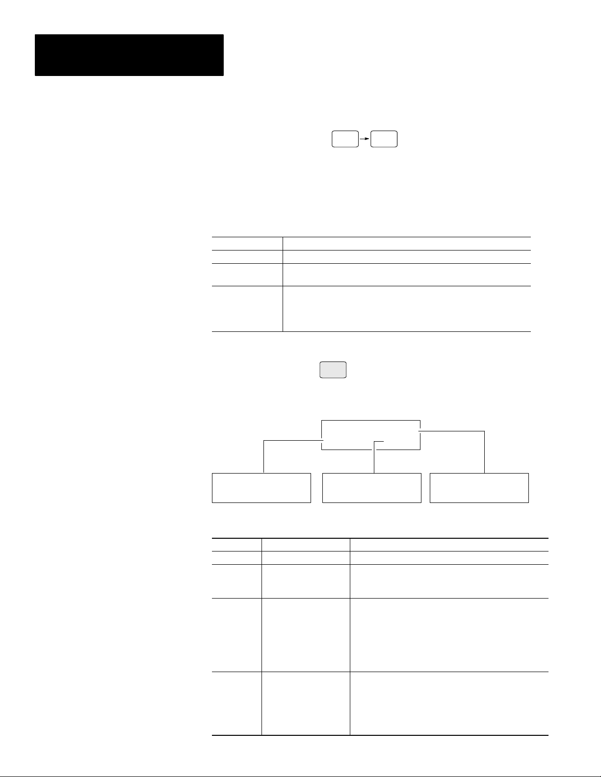
The following table lists the contents of each chapter:
Chapter Title Purpose
1 Using this Manual Provides an overview of the manual.
2 Overview of DTAM Micro
3 Initial Setup and Main Menu
4 Transferring Application Files
5 Running Applications
6 Installation
7
8
Appendix A Specifications
Appendix B Cable Diagrams
Appendix C
Communication
Connections and Setup
Troubleshooting
and Maintenance
DTAM Micro Special
Controller Functions
Contains a description of the DTAM
Micro and accessory devices.
Describes initial desktop setup of the
DTAM Micro using main menu functions.
Describes how to upload and download
application files between the DTAM Micro
and a personal computer.
Describes the basic screen types.
Also describes the different function
key operations.
Provides procedures for mounting the
DTAM Micro. Also provided are wiring
instructions and recommendations.
Describes RS-232 and RS-485
connections. Setup guidelines are
provided for SLC and PLC controllers.
Provides assistance in identifying
and correcting common operating
problems. Cleaning recommendations
are also provided.
Provides the specifications, agency
ratings, and European Union Directive
Compliance.
Provides the DTAM Micro cable
diagrams.
Provides the special control functions.
1–1
Page 8

Chapter 1
Using this Manual
Intended Audience
Conventions
No special knowledge is required to operate the DTAM Micro. If you are
installing the DTAM Micro, you must be familiar with the standard panel
cutout and installation techniques. If you are wiring the DTAM Micro, you
must be familiar with the electrical codes in your area (see inside front
cover).
You should be familiar with the DTAM Programming Software (see related
publications below).
This manual uses the following conventions:
• Keys that you press on the DTAM Micro are enclosed in brackets [ ].
For example: [NEXT] refers to the NEXT key on the DTAM Micro.
• References to menus are initial cap followed by the word Menu.
For example: Special Menu, Main Menu, Other Menu
• All DTAM Micro displays are shown inside a rectangular box.
1 Reset 3 Special
2 Com-Port 4 Other
Related Publications
1–2
The following publications may be helpful for additional reference.
DT AM Micro Publications
Publication Number Title
2707-801
Wiring Publications
1770-6.2.2
SLC Publications
Publication Number Title
1747-6.21
1747-UM011
1747-RM001 SLC 500 Reference Manual
DTAM Programming Software Programming Manual
(Series J or later Software)
Data Highway / Data Highway Plus / Data Highway-485
Cable Installation Manual
SLC 500 Fixed Hardware Style
Installation and Operation Manual
SLC 500 Modular Hardware Style
Installation and Operation Manual
Page 9

Chapter 1
Using this Manual
PLC-5 Publications
Publication Number Title
1785-6.1 PLC-5 Instruction Set Reference
1785-6.2.1 1785 PLC-5 Programmable Controllers Design Manual
1785-6.6.1
1785-7.1 PLC-5 Programmable Controllers Quick Reference
PLC-5 Family Programmable Controllers Hardware
MicroLogix Publications
Publication Number Title
1747-6.3 MicroLogix 1000 User Manual
1747-6.2.1 MicroLogix 1000 Quick Reference Guide
Installation Manual
1–3
Page 10

Chapter 1
Using this Manual
1–4
Page 11

Chapter
Objectives
A–B
2
DTAM Micro Overview
This chapter describes the DTAM Micro and accessories.
It contains these sections:
Section Page
General Information 2–1
Package Contents 2–2
Description 2–2
Keypad 2–5
DIP Switches 2–7
Communications Port 2–8
RS-232 Communications 2–9
RS-485 Communications 2–10
Compatibility NO TAG
Programming the DTAM Micro 2–11
Default Settings 2–12
Product Options 2–13
Product Accessories 2–13
General Information
The DTAM Micro interfaces with the PLC-5 and SLC 500 family of
processors. The DTAM Micro allows operators to monitor and manipulate
process data on the plant floor.
RS-232 or RS-485 Port. The DTAM Micro has either an RS-232 port
(Catalog No. 2707-M232P3) or an RS-485 port (Catalog No. 2707-M485P3).
The RS-232 port allows point-to-point connections with a PLC-5 or SLC
5/03, 5/04, 5/05. The RS-485 port provides network or point-to-point
capability with a PLC-5 (over RS-422), SLC or other DH485 device.
Memory Capability. Storage of the PLC-5 DF1 or SLC DH-485 driver
(communications protocol), configuration information, and user-programmed
screens are maintained in nonvolatile memory providing storage for
approximately 244 screens.
Recipe Operations. Recipe type functions allow operators to quickly
modify blocks of data. Download data to a maximum of 10 non-sequential
register addresses per screen. Link multiple recipe screens to download data
to more than 10 addresses.
Flexible Function Key Operations. Eight function keys provide a
convenient way to trigger screen displays and change display screens.
Point-Access/Display Function. Allows you to monitor or modify data files
in SLC or PLC controllers. Use this function to setup and debug application
programs.
2–1
Page 12
Chapter 2
DTAM Micro Overview
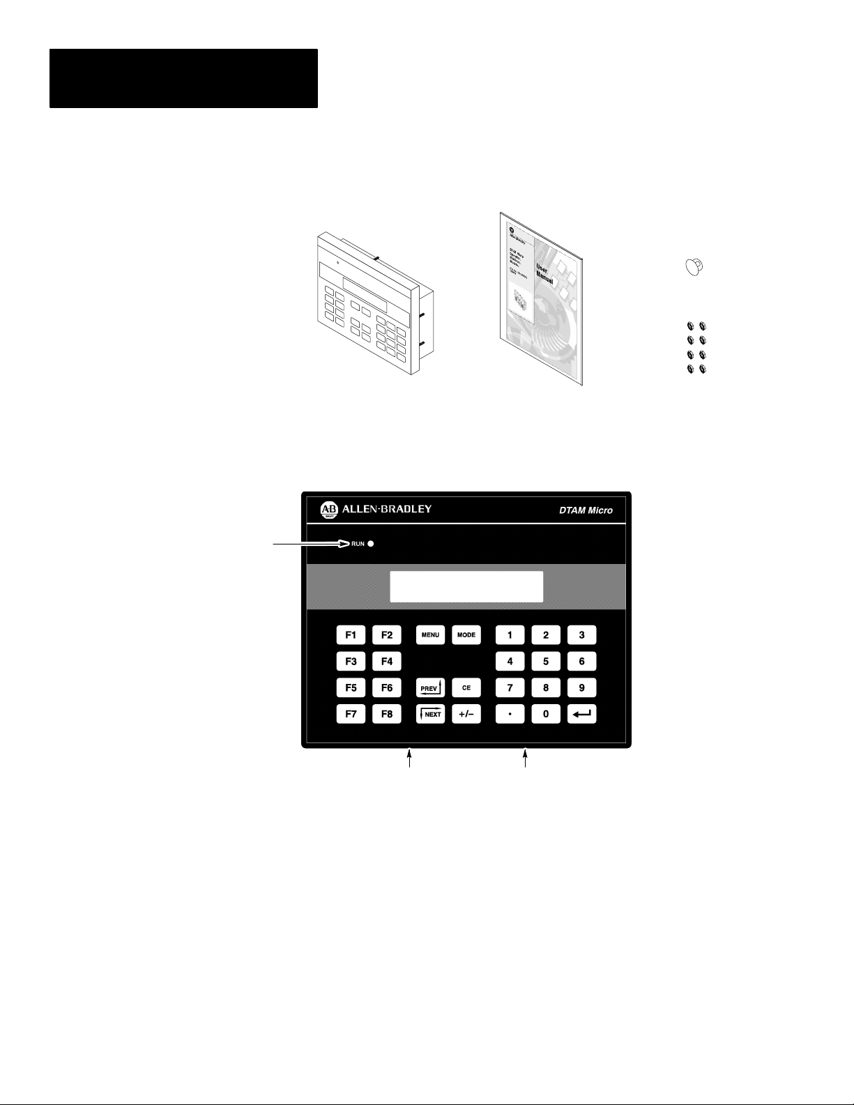
Package Contents
Description
LED Indicator
The DTAM Micro shipping box contains the following:
DIP Switch Cover
DTAM Micro
User Manual
(Catalog No. 2707–UM002)
Mounting Nuts (8)
The front panel of the DTAM Micro terminal is shown below.
Figure 2.1
DT AM Micro (front view)
Display Window
(2 Spare)
2–2
Power Connector
Communications Port
Display
The 2 line by 20 character display uses high contrast LCD technology with
LED backlighting.
Keypad
The keypad is separated by color into easily identified groups or functions. In
addition, each key has a raised dome in the center to provide tactile feedback.
The keypad is designed for hand operation. Using any other object or tool
may damage the overlay or key.
LED Indicator
A RUN LED in the upper left corner of the terminal indicates proper
operation of the DTAM Micro. This LED illuminates after the DTAM Micro
passes the self diagnostic tests.
Page 13
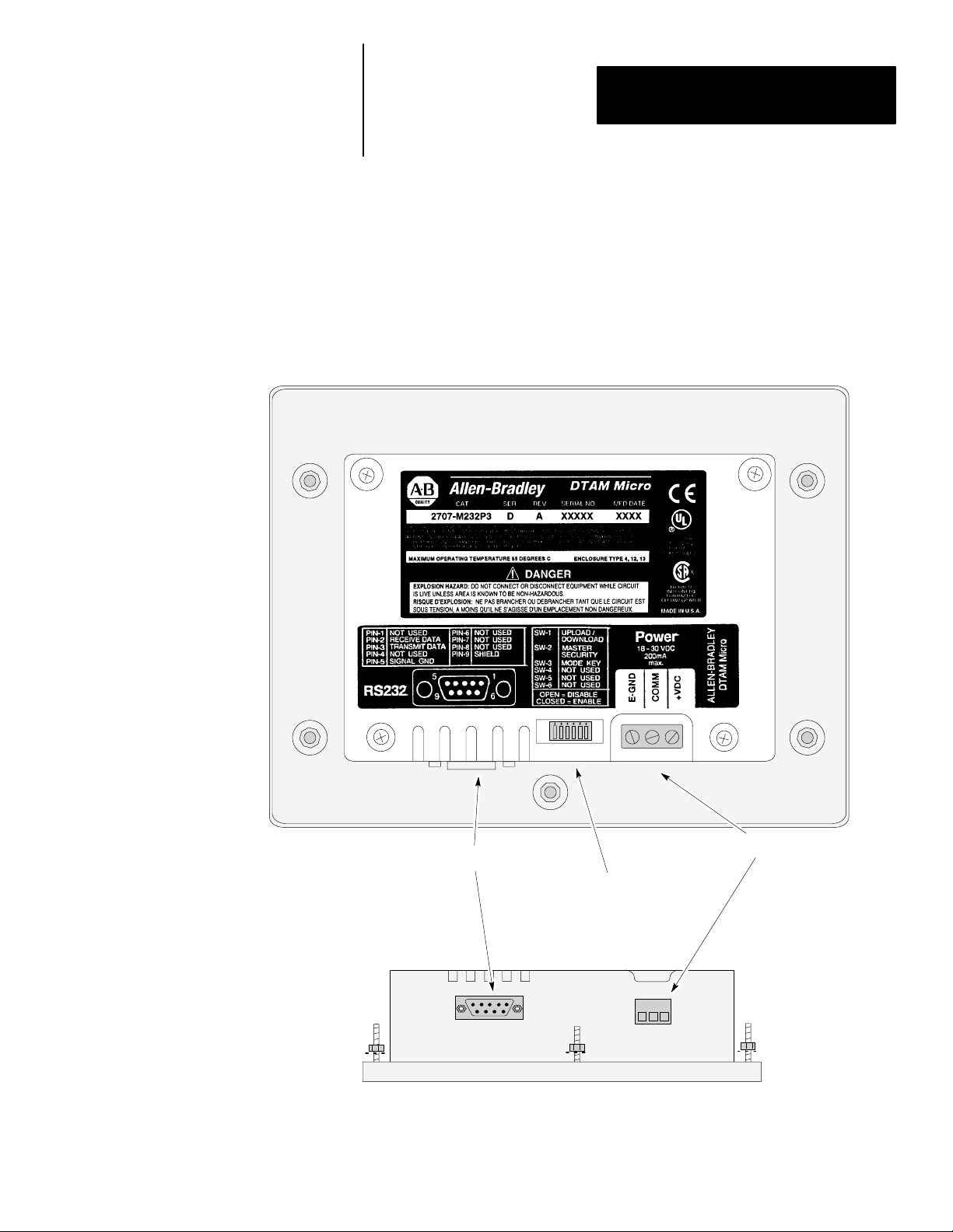
Figure 2.2
DT AM Micro (back & bottom view)
Back View (RS-232 version shown)
Chapter 2
DTAM Micro Overview
Communications Port
Power Connector
DIP Switch
(Behind Removable Cover)
Bottom View
2–3
Page 14

Chapter 2
DTAM Micro Overview
Communications Port
The DTAM Micro has either an RS-232 or RS-485 port.
• Catalog No. 2707-M232P3 has RS-232 port
• Catalog No. 2707-M485P3 has RS-485 port
DIP Switch
A six position DIP switch selects various operating settings. This switch is
located under a removable cover on the back. To remove cover, align cover
tabs with notches in hole.
Power Connector
The power connector is a non-removable, screw terminal block located on
the bottom of the unit. Connect 24 VDC to these terminals or use the
optional AC to DC Adapter.
2–4
Page 15
Chapter 2
DTAM Micro Overview
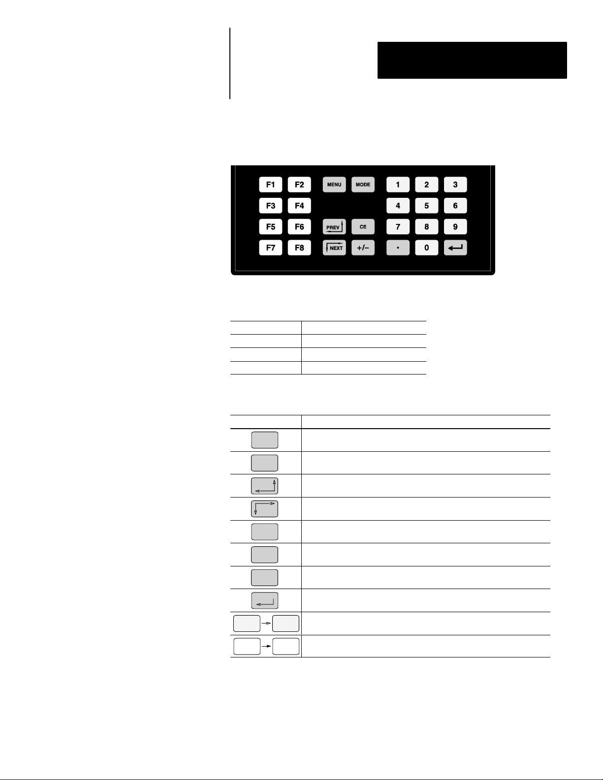
Keypad
Figure 2.3
Keypad
The DTAM Micro uses a sealed membrane, tactile feedback keypad. The
keys are color coded to easily identify key functions.
Key Color Function
Blue Movement/Operator Response
Dark Grey Display/Format Control
Light Grey Numeric Entry
The following table defines the function of each keypad key.
Key Function
MENU
MODE
PREV
NEXT
CE
+ \ –
D
Returns to the main menu of an application. If an alarm screen is triggered, the MENU key is not functional until the alarm is acknowledged.
Accesses special features and configuration operating parameters. DIP
switch SW-3 enables or disables the MODE key.
Steps back through a sequence of linked screens.
Steps forward through a sequence of linked screens.
Clears an entire value during data entry.
Toggles a data entry value between positive or negative.
Enters a decimal point.
Sends data to the controller. Data includes default values or data entered
at the keyboard. Also used to acknowledge alarm screens.
0 9
F1 F8
Enters numbers 0 to 9 during data entry or selects a numbered item
shown on the display.
Displays any application screen assigned to the key. These keys can also
set or clear bits at eight consecutive registers in the controller data table.
2–5
Page 16
Chapter 2
DTAM Micro Overview
Function Key Operations F1 F8
Function keys can be linked to application screens allowing quick access to
critical data display or data entry screens. For example, the F1 function key
is linked to Recipe Screen 10. The operator can press F1 at any point in the
application to download recipe registers on screen 10 to the processor.
A control mode can be assigned to each function key linked to a screen.
Control Mode Function
Auto Return Returns to the screen displayed before the function key was pressed.
Continue
Bit Write Mode
Continues to the next screen in the link regardless of the screen displayed
before the function key was pressed.
Allows the function key when pressed to set or clear a bit in the controller.
Bit Write Mode operates with either Auto Return or Continue mode.
The function keys access 8 contiguous word data elements defined by the
user. For example, assign function keys F1 to F8 to N7:20 → N7:27.
MODE Key Operations
MODE
The MODE key accesses a menu of options allowing you to set features and
operating parameters of the DTAM Micro.
1 Reset 3 Special
2 Com-Port 4 Other
1 Baud Rate 3 Parity
2 Data Bits 4 Exit
Mode Menu Select this option: To perform this function:
1 Reset Performs a system reset.
1 Baud Rate
2 Com-Port
3 Special
2 Data Bits
3 Parity
1 P-A/D
2 Mode
3 Memory Xfr
1 Master 3 Simulate
2 Scale 4 Test 5 Ex
Specifies 300, 1200, 2400, 4800, 9600, 19200, 38400
Specifies 7 or 8 data bits.
Specifies even, odd or none parity.
Displays and/or modifies data files in the processor.
Places processor in RUN mode or PROGRAM mode.
Transfers memory between a memory module and an SLC
or PLC5. The processor must be in PROGRAM mode.
1 P-A/D 3 Mem Xfr
2 Mode 4 Clr Flt
2–6
4 Other
4 Clr Flt
1 Master
2 Scale
3 Simulate
4 Test
Clears all processor faults in the PLC-5 or SLC 500.
Modifies the master security code of the DTAM Micro.
Converts controller values to engineering units.
Verifies an application without controller connected.
Tests memory, communications, keyboard and display.
Page 17
Chapter 2
DTAM Micro Overview
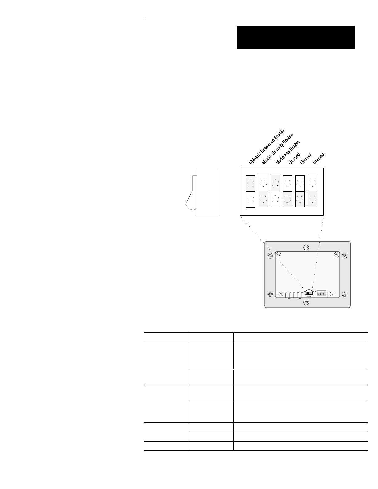
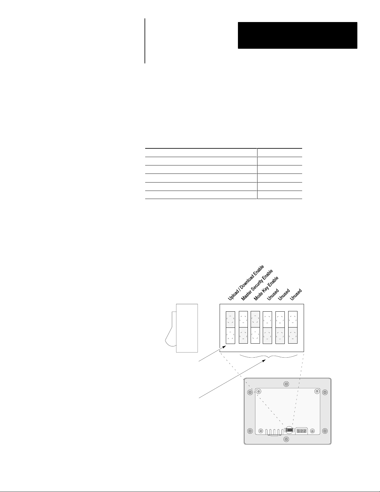
DIP Switches
The 6 position DIP switch allows you to enable or disable certain functions.
The DIP switch is accessed by removing the access cover on the back (access
cover is shipped in the hardware bag on new units).
Figure 2.4
DIP Switch
Side View
123456
ON =
OPEN
Back of DTAM Micro
Switch Position Setting Function
ON position allows the transfer of application files between
ON
1➀
OFF
ON
2
OFF
3
4, 5, 6 ON or OFF Reserved for future use.
➀ DTAM Micro is reset each time this switch position is changed.
ON ON enables the Mode key on the front panel.
OFF OFF disables the Mode key on the front panel.
the DTAM Micro and personal computer running DPS. All
communication between the DTAM Micro and controller are
disabled. Keypad entry is also disabled.
OFF enables communication between the DTAM Micro and
controller.
ON enables the master code. Enabling the master code
allows any security code to be accessed or modified.
OFF disables the master code. Disabling the master code
still allows access to a security screen or special functions
but does not allow security codes to be modified.
2–7
Page 18
Chapter 2
DTAM Micro Overview
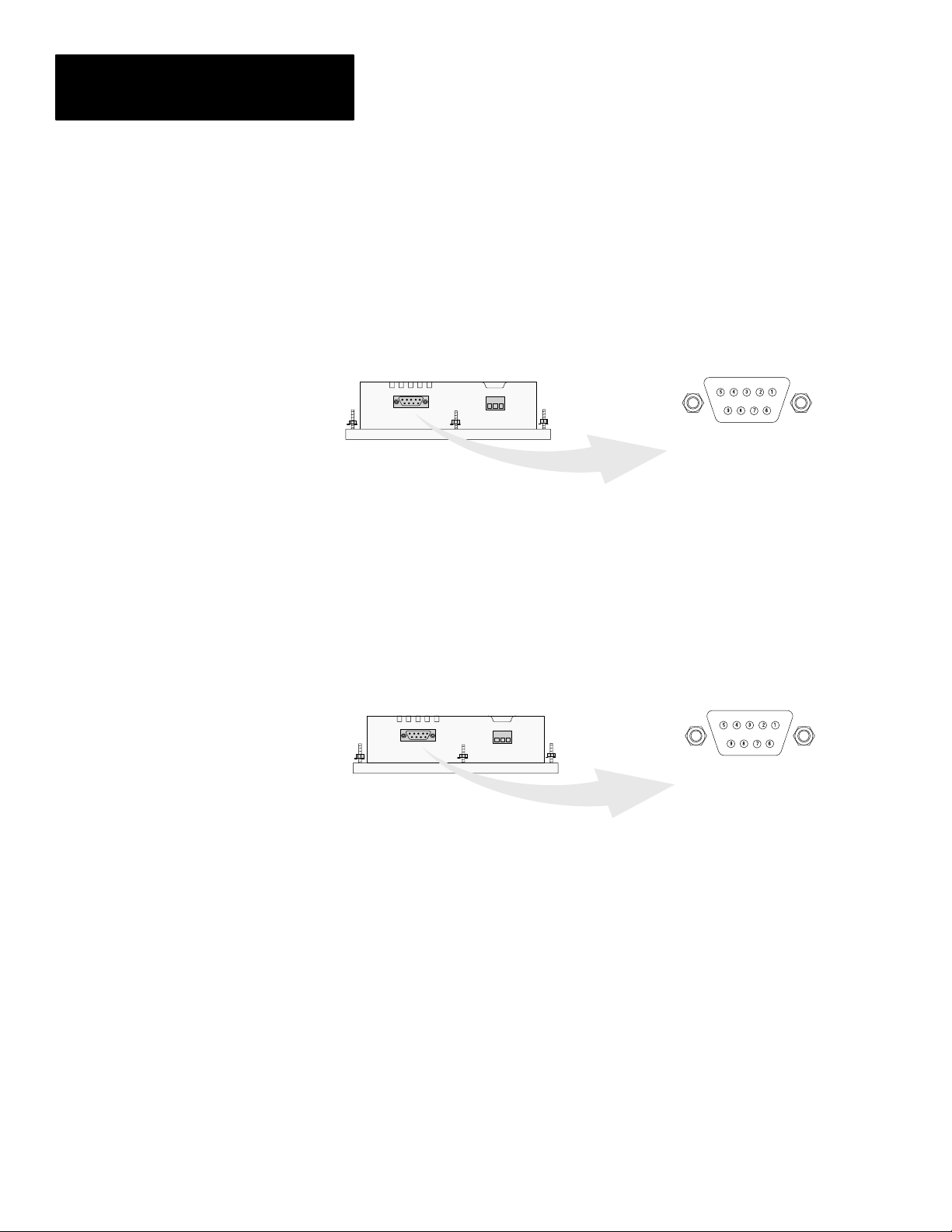
Communications Port
All communications are through a 9 pin connector on the bottom of the
DTAM Micro. The connector is either an RS-232 port or RS-485 port
depending upon the version catalog number.
Figure 2.5
Communications Port
DTAM Micro
(Bottom View)
RS-485 Version
(Catalog No. 2707-M485P3)
9 Pin Female
PIN # Signal Name
1 Data Out –
2 Data Out +
3 Data In 4 Data In +
5 Signal Ground
6 Transmit Enable
7 Not Used
8 Signal Ground
9 Shield
DTAM Micro
(Bottom View)
9 Pin Female
PIN # Signal Name
1 Not Used
2 Receive Data (RD)
3 Transmit Data (TD)
4 Not Used
5 Signal Ground
6 Not Used
7 Not Used
8 Not Used
9 Shield
RS-232 Version
(Catalog No. 2707-M232P3)
2–8
Page 19
Chapter 2
DTAM Micro Overview
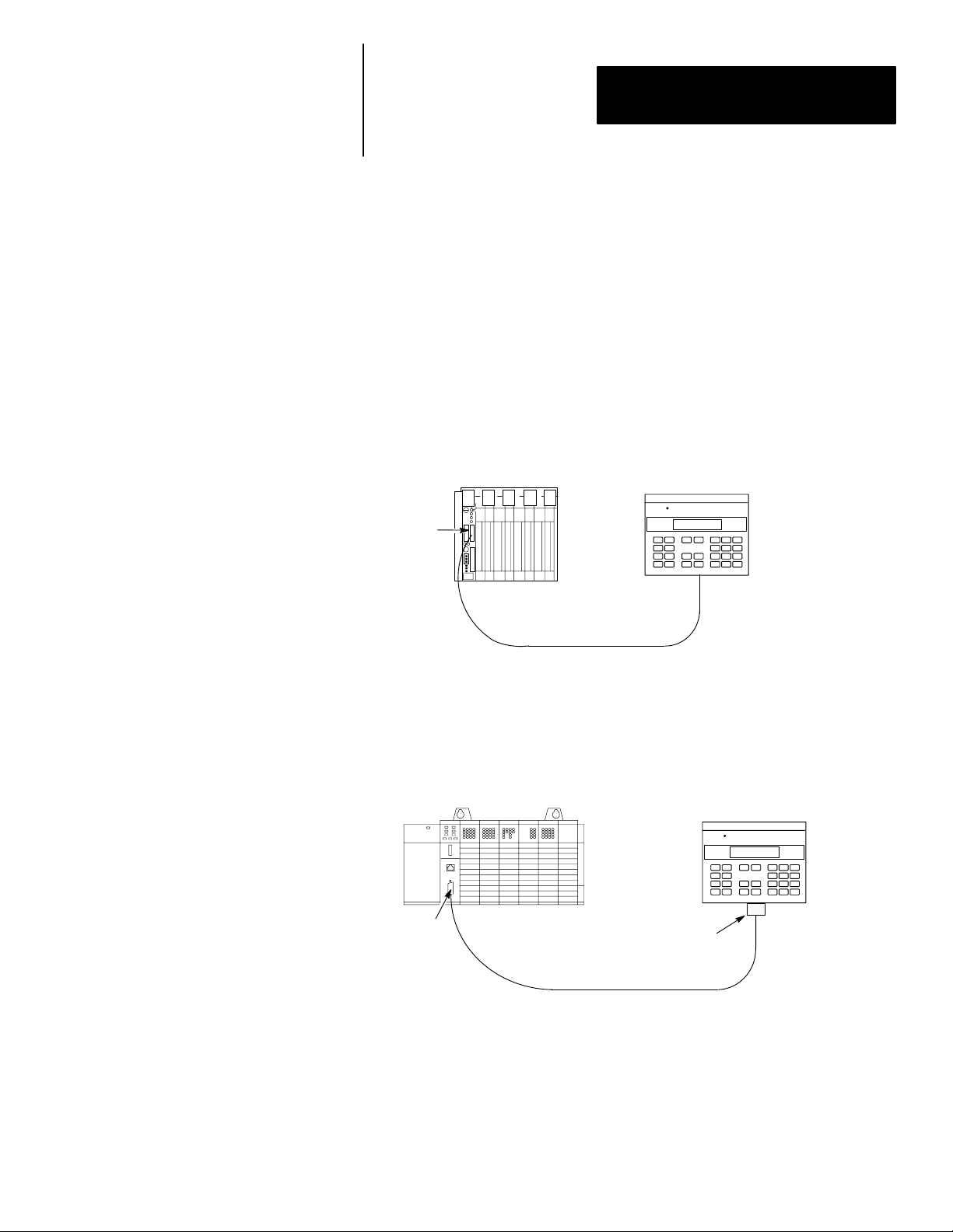
RS-232 Communications
RS-232 Version (Catalog No. 2707-M232P3)
The RS-232 port allows point-to-point communications with:
• PLC-5 Channel 0 (configured as RS-232 port, DF1 protocol)
• SLC 5/03, 5/04, 5/05 RS-232 port (DH485 protocol)
• MicroLogix 1000
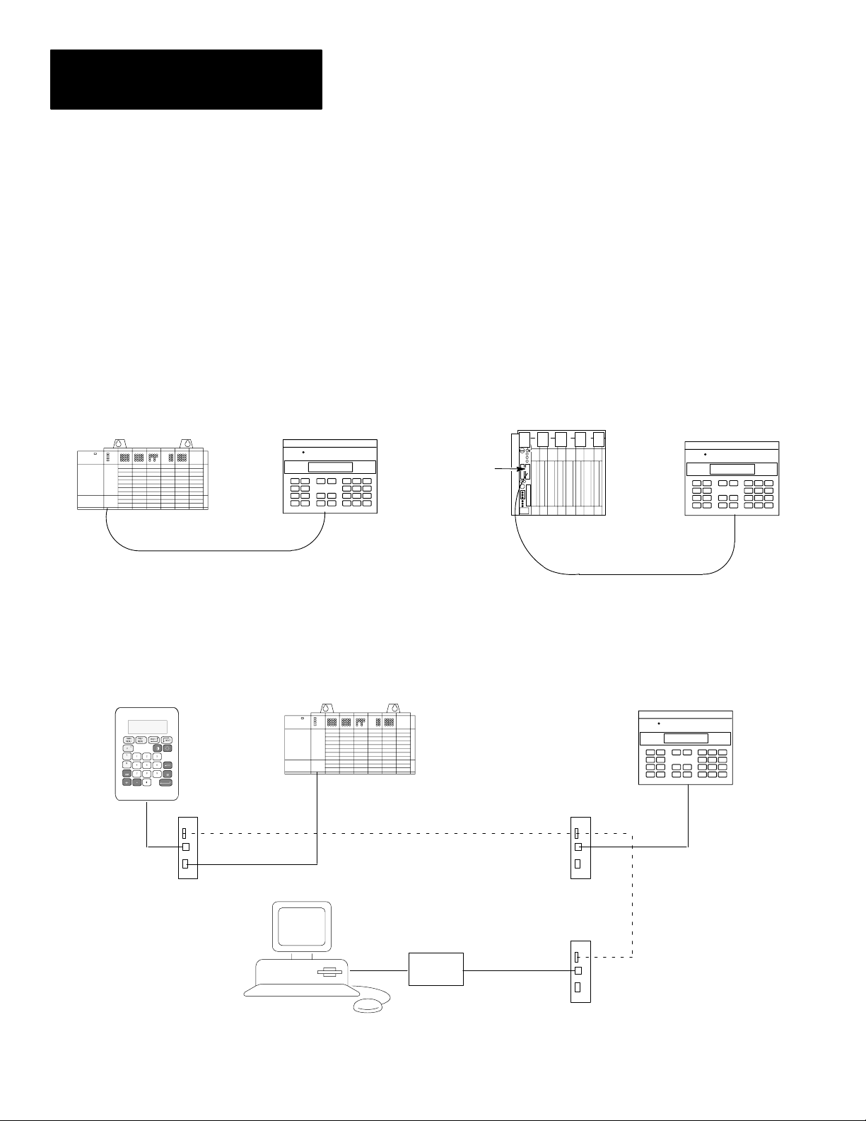
Figure 2.6
Typical RS-232 Communications
DTAM Micro to PLC-5 Channel 0
PLC-5
Channel 0
RS-232
Cable (Catalog No. 2707-NC3)
DTAM Micro
DTAM Micro
RS-232 Port
Channel 0
SLC 5/03
DTAM Micro to SLC 5/03, 5/04, 5/05
Gender
Adapter
RS-232
Cable (Catalog No. 1747-CP3)
Gender Adapter Required
DTAM Micro
DTAM Micro
RS-232 Port
2–9
Page 20
Chapter 2
DTAM Micro Overview
RS-485 Communications
DTAM Micro to Single SLC DTAM Micro to PLC-5 Channel 0
SLC
RS-485
Cable (Catalog No. 2707-NC1)
RS-485 Version (Catalog No. 2707-M485P3)
The RS-485 port allows point-to-point and multi-drop communications with:
• PLC-5 Channel 0 (configured as RS-422 port, DF1 protocol)
• SLC 500 DH-485 port
• MicroLogix 1000 using the AIC+ Interface
Figure 2.7
Typical RS-485 Communications
DTAM Micro
DTAM Micro
RS-485 Port
Channel 0
PLC-5
RS-422
Cable (Catalog No. 2707-NC4)
DTAM Micro
DTAM Micro
RS-485 Port
2–10
DTAM Plus
Link Coupler
Programming Terminal
DTAM Micro to DH-485 Network
SLC
DH-485
Interface
Converter
RS-232 to RS-422
Link Coupler
Link Coupler
DTAM Micro
DTAM Micro
RS-485 Port
RS-485
Cable
(Catalog No. 2707-NC1)
Page 21
Chapter 2
DTAM Micro Overview
Programming the DTAM Micro
The DTAM Micro is programmed off-line using a personal computer running
DTAM Plus Programming Software (DPS). Operating system upgrades are
also transferred using a personal computer.
DTAM Programming Software (DPS)
Use DPS software (Catalog No. 2707-NP, Series H or later) to create
application screens for both the DTAM Micro and DTAM Plus Operator
Terminals. For a description of DPS, refer to the Programming Manual
(Publication No. 2707-801).
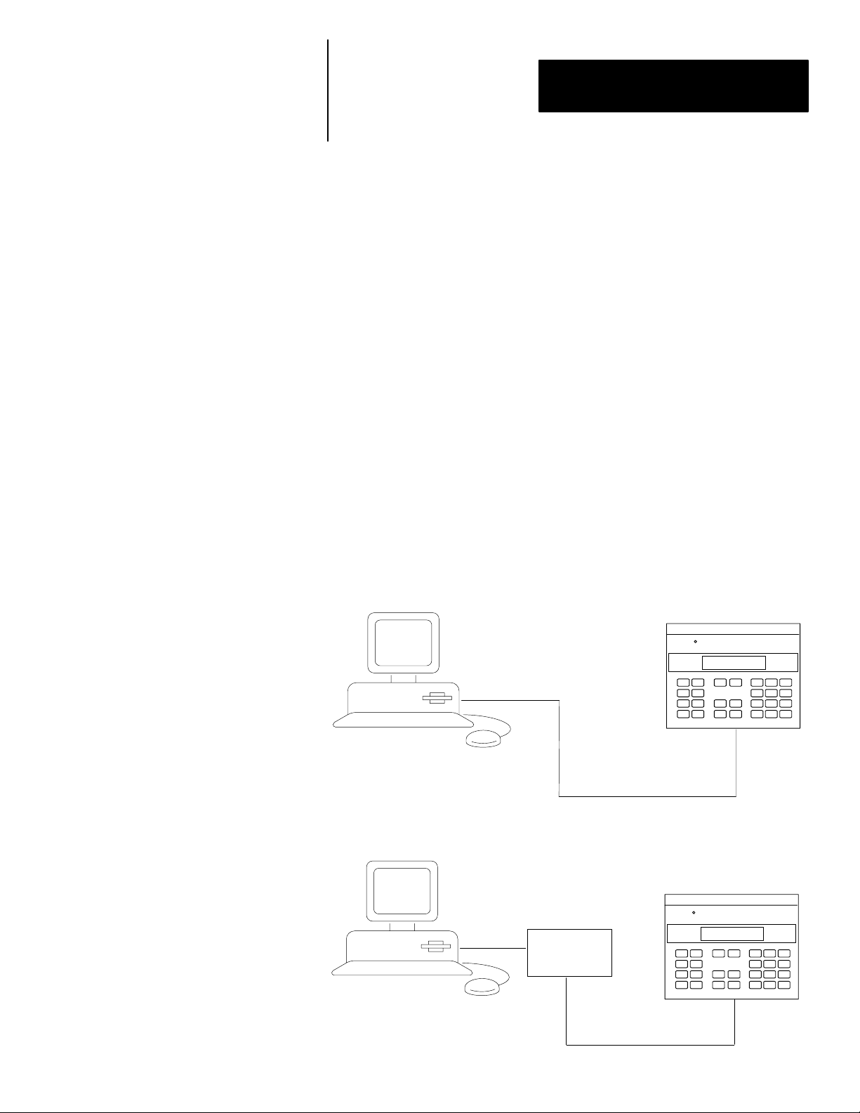
Upload/Download Connections
For programming and configuration, the DTAM Micro is connected to your
computer’s RS-232 port. If you have a DTAM Micro RS-485 version, an
RS-232 to RS-422 converter cable (Catalog No. 2707-NC5) is required. The
RS-485 version of the DTAM Micro is compatible with the converter cable’s
RS-422 output.
Upload/Download Connection to RS-232 DTAM Micro
Programming Terminal
(Catalog No. 2707-NC2)
Upload/Download Connection to RS-485 DTAM Micro
RS-232 to RS-422
Interface
Converter
Built Into Cable
Programming Terminal
(Catalog No. 2707-NC5)
Cable
Cable
DTAM Micro
RS-232 Port
DTAM Micro
RS-485 Port
2–11
Page 22
Chapter 2
DTAM Micro Overview
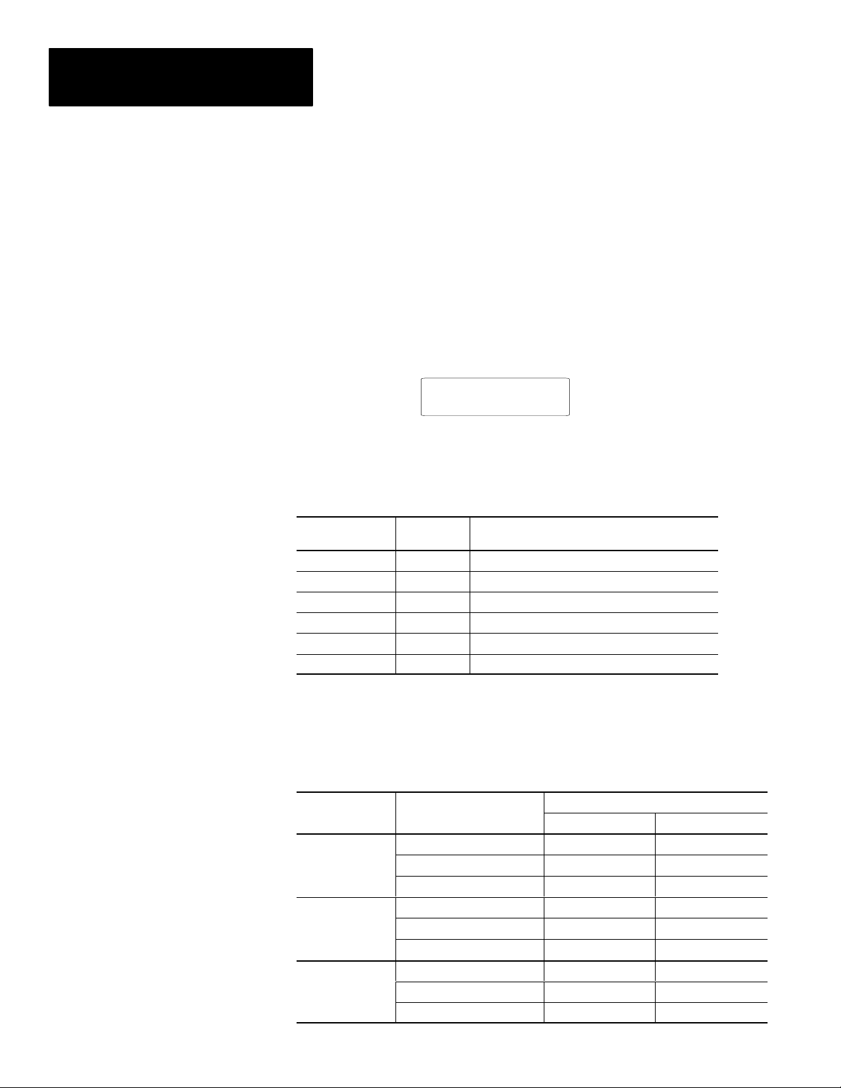
Default Settings
The DTAM Micro is preset at the factory with the following defaults:
Operating System
The DTAM Micro is provided with a default application file:
• RS-485 version has DH-485 operating system file
• RS-232 version has PLC-5 DF1 operating system file
The application file displays a screen with the message:
Bul 2707 DTAM Micro
No Program loaded
DIP Switch Settings
The DTAM Micro is shipped with the following DIP Switch settings:
DIP Switch
Position
1 ON Upload/Download Enabled
2 OFF Master Security Disabled
3 ON Mode Key enabled
4 OFF Not Used
5 OFF Not Used
6 OFF Not Used
Default
Setting
Function
2–12
Operating Parameters
The following operating functions can be set using the DTAM Micro menu
functions. Refer to Chapter 3.
Function Parameter
Baud 19200 2400
C-Port
Special
Other
Data Bits
Parity Even None
DTAM Micro Node 00 N/A
Max. Node 02 N/A
Controller Node 01 N/A
Simulate Off Off
Master Code
Scale On On
RS-485 Version RS-232 Version
00000000 00000000
Default Value
8 8
Page 23

Chapter 2
DTAM Micro Overview
Product Options
Product Accessories
The table below lists the options available for the DTAM Micro.
Table 2.A
DT AM Micro Base Items
Item Catalog No. Description
DTAM Micro 2707-M485P3 DTAM Micro with RS-485 Communications Port
DTAM Micro 2707-M232P3 DTAM Micro with RS-232 Communications Port
Programming
Software
2707-NP
(Series H or later)
Use to create application screens for the DTAM Micro on
a personal computer. Software allows completed applications to be transferred between the DTAM Micro and a personal computer.
The following accessories are available for the DTAM Micro.
Table 2.B
Accessories
Item Catalog No. Description
RS-485 communication cable connects DTAM Micro to an
DH-485 Network
Interface Cable
RS-232
Upload/Download
Cable
RS-232
Communications Cable
RS-232
Communications Cable
RS-422
Communications Cable
RS-485
Upload/Download
Cable
RS-232
Communications Cable
120V AC to DC Adapter 1747-NP1
240V AC to DC Adapter 1747-NP2
➀ A 9-pin male to female gender adapter is required.
2707-NC1
2707-NC2
2707-NC3
1747-CP3➀
2707-NC4
2707-NC5
2707-NC10 RS-232 cable connects DTAM Micro to a MicroLogix 1000
SLC network. Cable has 9-pin male connector for the
communication port on the DTAM Micro and an 8-pin RJ
connector for the communication port on the SLC or Link
Coupler (Catalog No. 1747-AIC).
RS-232 cable connects DTAM Micro (RS-232 version)
and a personal computer. Use to upload or download
applications with a personal computer running DPS
software (Catalog No. 2707-NP, Series H or later).
RS-232 cable connects DTAM Micro to Channel 0 Port of
a PLC-5.
RS-232 cable connects DTAM Micro to Channel 0 Port
(configured for RS-232) of an SLC 5/03, 5/04, 5/05.
RS-422 cable connects DTAM Micro to Channel 0 Port
(configured for RS-422) of a PLC-5.
For use with RS-485 version of the DTAM Micro.
Transfers files between RS-485 port of the DTAM Micro
and the personal computer’s RS-232 port. Cable
converts RS-232 signals to RS-422 signals for the DTAM
Micro. Cable has a 25-pin male connector for the
computer port and a 9 pin male connector for the port on
the DTAM Micro.
Provides 18 to 30 VDC output for the DTAM Micro.
Operates on 120 VAC input line voltage.
Provides 18 to 30 VDC output for the DTAM Micro.
Operates on 240 VAC input line voltage.
2–13
Page 24

Chapter 2
DTAM Micro Overview
2–14
Page 25

Chapter
Objectives
A–B
3
Initial Setup and Mode Menu
This chapter describes how to apply power to and then configure the DTAM
Micro using the menu keys. Instructions on how to use the Simulate mode to
run an application are provided. This chapter contains the following
sections:
Section Page
Apply Power 3–2
Powerup Sequence 3–3
Mode Menu 3–4
Resetting the DTAM Micro 3–5
Setting Communication Parameters Manually 3–6
Special Functions for Controller Operations 3–7
Entering a New Master Security Code 3–8
Enabling / Disabling Scaling 3–9
Using the Simulate Mode 3–10
Test Functions 3–11
3–1
Page 26
Chapter 3
Initial Setup and Mode Main
Apply Power
This section describes power connections for initial desktop setup and
programming. Refer to Chapter 6 for installation wiring instructions.
The DTAM Micro is intended for 24 VDC systems. If 24 VDC is not
directly available, you can use the AC to DC Adapters: Catalog No.
1747-NP1 for 120 VAC or Catalog No. 1747-NP2 for 240 VAC power.
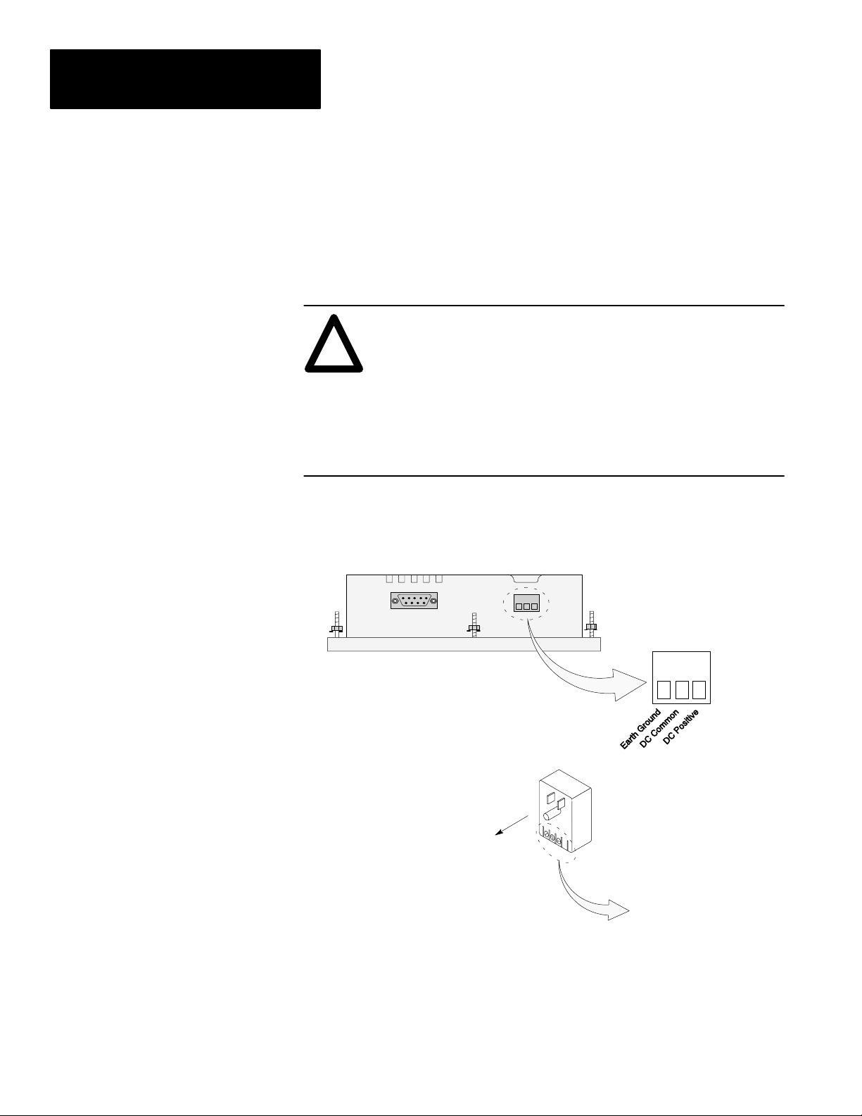
ATTENTION: Verify that the power is disconnected from the
power source before wiring. Failure to disconnect power may
!
result in electrical shock.
Make sure that the supply voltage to the DTAM Micro is 18 to 30
volts DC. The incorrect voltage may damage the DTAM Micro.
Do not overtighten the power connector screw terminals.
Overtightening the terminals may damage the DTAM Micro.
1. Connect the DC positive, DC common, and ground lines as shown below.
Verify the connections by checking the DC power supply labels on the
AC to DC Adapter (if used) and DTAM Micro.
DTAM Micro
Optional AC to DC Adapter
Catalog No. 1747-NP1, -NP2
To 120VAC (Catalog No. 1747-NP1)
To 240VAC (Catalog No. 1747-NP2)
To DTAM Micro. Check DC
power labels before making
connections.
2. Apply power to the DTAM Micro by plugging the AC to DC Adapter into
the proper power source (check Adapter label to verify voltage).
The DTAM Micro performs a powerup sequence.
3–2
Page 27
Chapter 3
ÎÎÎ
Initial Setup and Mode Menu
Powerup Sequence
The powerup sequence is automatic, you do not have to respond to
the screens. The sequence depends upon DIP switch position #1 (upload /
download enable). The DTAM Micro is shipped with this switch On.
Powerup Sequence (DIP Switch #1 On)
1. The DTAM Micro verifies the system memory checksum, program
checksum, and system RAM. After the test is completed, the result is
displayed with the current DIP switch settings.
Memory Check: pass
DIP Switch: 101000
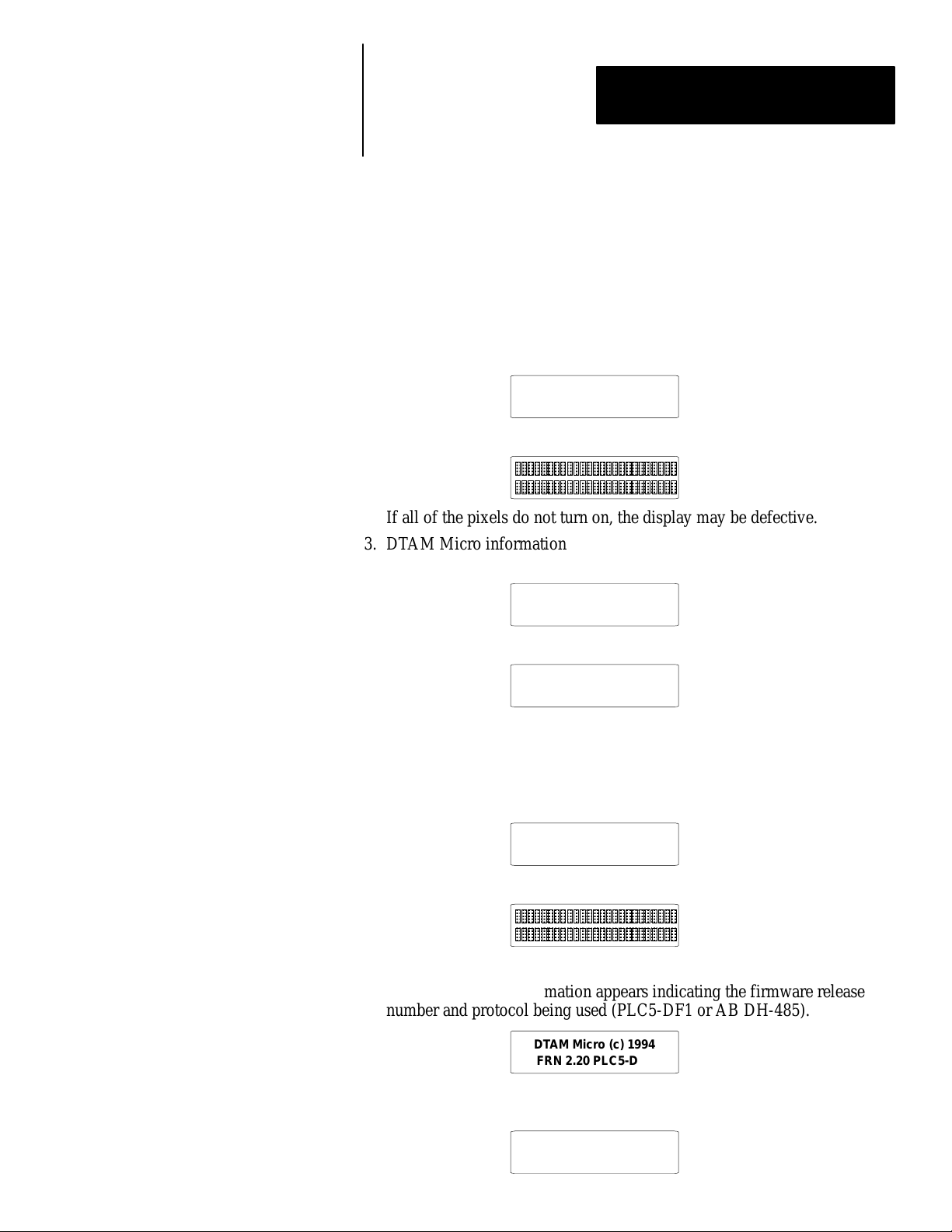
2. The display is tested, every pixel of the display is turned on.
If all of the pixels do not turn on, the display may be defective.
3. DTAM Micro information appears indicating the microprocessor core
firmware version and communication port (RS-232 or RS-485).
Operator Interface
Core: 3.00 RS-232
4. The DTAM Micro waits for an application download.
Programming Mode
Waiting Up/Download
Powerup Sequence (DIP Switch #1 Off)
1. The DTAM Micro verifies the system memory checksum, program
checksum, and system RAM. After the test is completed, the result is
displayed with the current DIP switch settings.
Memory Check: pass
DIP Switch: 101000
2. The display is tested, every pixel of the display is turned on.
If all of the pixels do not turn on, the display may be defective.
3. Operating system information appears indicating the firmware release
number and protocol being used (PLC5-DF1 or AB DH-485).
DTAM Micro (c) 1994
FRN 2.20 PLC5-DF1
4. The first application screen displays. If the DTAM Micro is being
powered up the first time you will see:
Bul. 2707 DTAM Micro
No Program Loaded
3–3
Page 28
Chapter 3
Initial Setup and Mode Main
Mode Menu
Access the Mode Menu by pressing the [MODE] key. All other functions are
halted when the menu is displayed.
Note: DIP switch SW-3 must be in the On position or the [MODE] key will
not function.
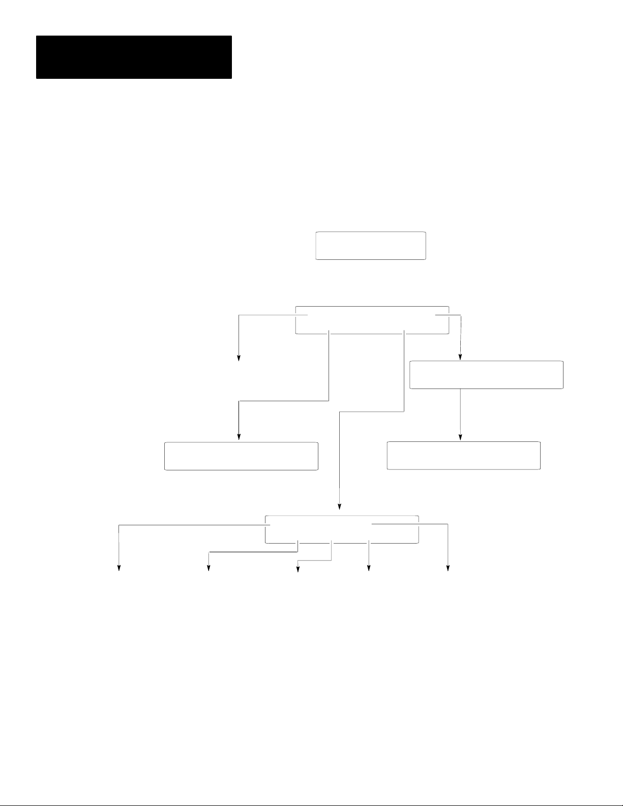
The Mode Menu provides access to four functions:
1 Reset 3 Special
2 Com-Port 4 Other
Select a menu item by pressing the corresponding numeric key [1] ! [4].
The menu structure is shown below:
1 Reset 3 Special
2 Com-Port 4 Other
Resets the DTAM Micro
SLC or 50X Address
1 = Edit Addr 0 = Bypass
(Only with DH485
Operating System)
1 Baud Rate 3 Parity
2 Data Bits 4 Exit
Configures DTAM Micro
Communications Port
Sets Master
Security Code ➀
➀ DIP switch position 2 must be On (master code enable).
Enables / Disables
Scaling
Functional Tests
1 Master 3 Simulate
2 Scale 4 Test 5 Ex
Performs
Exits to
Mode Menu
1 P-A/D 3 Mem Xfer
2 Mode 4 Clr Fault
Special
Controller Operations
Simulates Controller
Communications
3–4
Page 29

Chapter 3
Initial Setup and Mode Menu
Resetting the DTAM Micro
Use the reset function to reset the DTAM Micro after DIP switch changes or
a configuration change using the Mode Menu.
To reset the DTAM Micro:
1. From the Mode Menu select 1 Reset.
1 Reset 3 Special
2 Com-Port 4 Other
You are prompted:
1 = Reset DTAM Micro
0 = Abort
2. Press [1] on the keypad to initiate the reset.
The DTAM Micro resets. This has the same effect as turning the power
off and on. The DTAM Micro performs the self diagnostic tests and
powerup displays as described in the previous section.
3–5
Page 30

Chapter 3
Initial Setup and Mode Main
Setting Communication Parameters Manually
The Com-Port option on the Mode Menu lets you to manually adjust the
communication port parameters. Normally these parameters are set
automatically from the programming software when an application is
downloaded.
Select Com-Port from the Mode Menu.
1 Reset 3 Special
2 Com-Port 4 Other
This menu displays:
1 Baud Rate 3 Parity
2 Data Bits 4 Exit
Select an item by pressing the corresponding numeric key [1] ! [4].
Baud Rate
Selecting Baud Rate displays the current baud rate.
Baud Rate 19200
“Next” to change
Press [Next] to select a new rate: 300, 1200, 2400, 4800, 9600, 19200,
38400. DH-485 communications with an SLC or network cannot be set at
300 Baud.
Data Bits
Selecting Data Bits displays the current setting.
Data Bits 7
“Next” to change
Press [Next] to select either 7 or 8 bits.
Parity
Selecting Parity displays the current setting.
Parity Even
“Next” to change
Press [Next] to select Even, Odd, or No parity.
3–6
Page 31

Chapter 3
Initial Setup and Mode Menu
Special Functions for Controller Operations
The Special Menu item provides access to special features for the controller
operations. A security access code may be assigned in the application
restricting access to the Special Menu.
Select Special from the Mode Menu.
1 Reset 3 Special
2 Com-Port 4 Other
This menu displays:
1 P-A/D 3 Mem Xfr
2 Mode 4 Clr Fault
Note: Below are brief descriptions of each menu item.
Refer to Appendix C for instructions on using the Special Menu items.
P-A/D
Use the Point Access / Display function to display, and modify controller
data files. The P-A/D function does not allow you to write controller Input
and Output files. Appendix C provides a listing of the applicable file types
for SLC and PLC-5 controllers along with step-by-step instructions.
Mode
Select mode to place the controller in either the run or program modes. This
may be useful if you need to halt the controller for memory transfers.
Mem Xfer
Use the memory transfer function to initiate a transfer of data between a
memory module and an SLC or PLC controller. Memory transfers with a
PLC-5 are only to a memory module, you cannot transfer data from a
memory module to a PLC-5. Appendix C describes how to use the Mem
Xfer function.
Clr Fault
Use the Clear Fault function to clear all major and minor faults in the
controller.
3–7
Page 32

Chapter 3
Initial Setup and Mode Main
Entering a New Master Security Code
The master security code provides access to all security codes and allows
them to be modified. Two master security codes perform special functions:
00000000 allows the operator to modify the existing master code without
entering the current code.
99999999 does not allow operator to modify security codes. Changing of
the master security code is through DPS software.
To enter a new Master Security code:
1. From the Mode Menu, select item 4.
1 Reset 3 Special
2 Com-Port 4 Other
The Other Menu appears:
1 Master 3 Simulate
2 Scale 4 Test 5 Ex
2. Press [1] to select the Master security code function.
The master code entry screen displays:
Enter Current Master
Code:_
3. Enter the current code and press [ ].
You are prompted to enter the new code.
Enter New Master
Code:_
4. Enter a new code. The code must be 8 digits in length. If you enter less
than 8 digits the entry is padded with zeroes. For example, an entry of
1234 is entered as12340000.
Note: Security codes can contain the wildcard character ? Any entered
value will be seen as a match to the wildcard. You must make sure that the
master security code is different from security codes using wildcard entries.
Otherwise the master security code may be seen as a security code. For
example, if the:
Security Code =12??????
Master Code = 12368794
When the master security code above is entered, the DTAM Micro interprets
it as a security code.
3–8
Page 33

Chapter 3
Initial Setup and Mode Menu
Enabling / Disabling Scaling
Use scaling to convert data from a controller to engineering units such as
gallons or psi. When scaling is disabled, the values are not converted. Refer
to the DTAM Programming Software Manual for a description of how values
are scaled. The scaling factor is determined by the application designer, it
cannot be changed by the operator.
Flow = 16
Gallons Per Minute
Flow Rate
Transducer
Flow Rate
Transducer
Value = 510
PLC-5
Controller = 510
DTAM Micro displays
scaled value of
16 Gallons Per Minute
Value From
To enable or disable scaling:
1. From the Mode Menu, select item 4.
1 Reset 3 Special
2 Com-Port 4 Other
The Other Menu appears:
1 Master 3 Simulate
2 Scale 4 Test 5 Ex
2. Select item 2.
The scale enable screen displays:
Scale Enable OFF (0)
0=Off 1=On
Current Setting
3. Press [1] on the keypad to enable scaling and [0] to disable scaling.
You are returned to the Other Menu.
4. Select item 5 to exit to the Mode Menu.
3–9
Page 34

Chapter 3
Initial Setup and Mode Main
Using the Simulate Mode
The Simulate mode checks an application without having a controller
connected. All data that normally would be sent by the controller, such as
data for a display, is set to 0. Any ASCII data is set to ? (PLC5-DF1
operating system only). Selecting Simulate from the Mode Menu will:
• Halt communication between the DTAM Micro and the controller.
• Simulate communication with a controller.
Disabling the Simulate mode resumes normal operation.
To simulate an application:
1. Download the application from the DPS software.
2. Enable the Simulate mode.
3. From the Mode Menu, select item 4.
1 Reset 3 Special
2 Com-Port 4 Other
The Other Menu appears:
1 Master 3 Simulate
2 Scale 4 Test 5 Ex
4. Select item 3.
The simulate enable screen displays:
Simul Enable OFF (0)
0=Off 1=On
Current Setting
5. Press [1] to enable the Simulate mode.
6. Press [5] to exit the Other Menu and display the Mode Menu.
7. From the Mode Menu, reset the DTAM Micro. Refer to page 3–5.
The DTAM Micro displays a series of diagnostic tests, enters run mode,
loads the application and then displays the Mode Menu of the application.
8. Run the program as you normally would. Notice that all display registers
show data as a set of zeroes.
Pressure = 0000 PSI
Data Display
9. After verifying the operation of the program, press the [MODE] key.
All other functions are halted and the Mode Menu is displayed.
10. Disable the Simulate mode.
3–10
Page 35

Chapter 3
Initial Setup and Mode Menu
Test Functions
Selecting Test from the Other Menu displays the test screen:
DTAM Micro Diag Test
< Test Selection >
Current Test Selection
Use the Test menu to perform the following:
• Reset DUT (DTAM Under Test)
• DIP switch positions
• Display
• Keyboard
• Communications port
• Random Access Memory (RAM)
• System memory
• Program memory
• Transmit enable
Refer to Chapter 8 Troubleshooting and Maintenance for instructions on how
to perform these tests.
3–11
Page 36

Chapter 3
Initial Setup and Mode Main
3–12
Page 37
Chapter
Objectives
Upload / Download DIP Switch Settings
A–B
4
Transferring Applications
This chapter describes how to transfer applications between the offline
programing software (DPS) and the DTAM Micro. It contains the
following sections:
Section Page
Upload/Download DIP Switch Settings 4–1
Upload/Download Connections 4–2
Computer Setup 4–2
Downloading an Application 4–3
Uploading an Application 4–8
Before you can upload or download an application, you must verify that
DIP switch position #1 is On as shown. To access the DIP switch, remove
the cover from the access hole on the back of the DTAM Micro (align cover
tabs with notches in hole to remove). The DTAM Micro is shipped without
the cover installed, you can find it in the hardware bag.
Side View
ON =
DIP Switch Position #1
must be On as shown.
DIP Switch Positions #2
through #6 can be in any position.
123456
OPEN
Back of DTAM Micro
4–1
Page 38

Chapter 4
Transferring Applications
Upload / Download Connections
RS-485 Version (Catalog No. 2707-M485P3)
Use Upload/Download Cable (Catalog No. 2707-NC5)
RS-232 Version (Catalog No. 2707-M232P3)
Use Upload/Download Cable (Catalog No. 2707-NC2)
To download an application to the DTAM Plus, you must:
• connect a power supply (refer to Chapter 3)
• connect the (Catalog No. 2707-NC2) upload/download cable if you have
the RS-232 version
• connect the (Catalog No. 2707-NC5) upload/download cable if you have
the RS-485 version. This cable converts the computer’s RS-232 output to
RS-422 which is compatible with the DTAM Micro RS-485 port.
DTAM Micro
Refer to Chapter 3
for power connections.
To Computer
RS-232 Port
Computer Setup
4–2
Upload and download functions are initiated from a personal computer
running the programming software DPS (Catalog No. 2707-NP, series H or
later). Transfer functions automatically occur at 9600 Baud.
After the transfer is complete, the DTAM Micro Baud rate is set to the
parameters defined by the application program residing in the DTAM Micro.
Page 39

Chapter 4
Transferring Applications
Downloading an Application
. You will not see this prompt if
a monitor was specified during
installation.
This section shows how to download an application from a computer running
DPS software (Catalog No. 2707-NP, series H or later) to the DTAM Micro.
Refer to the DPS Programming Manual (Publication No. 2707-801) for
additional information.
1. Apply power to the DTAM Micro.
The following message appears in the window of the DTAM Micro.
Programming Mode
Waiting For Program
If you do not see this message, check the DIP switch settings.
DIP Switch position #1 must be in the Closed (ON) position.
2. On your computer, move to the /DPS subdirectory where the software
resides.
C:\DPS>
3. Type dps and press [Return] to start the program.
C:\DPS>dps [Return]
4. Specify whether you are using a color monitor. Enter Y or N.
5. The startup screen displays:
Technical Support
Voice: 440–646–6800
FAX: 440–646–6850 or 6890
E–mail: RACLEASKTHEEXPERT@RA.ROCKWELL.COM
4–3
Page 40

Chapter 4
Transferring Applications
. You will not see this prompt if
a product type was specified
during installation.
6. Press any key (other than [Esc]) to continue.
The Product Selection Menu appears.
7. Press [Return] to select the DTAM Micro product.
The Opening Menu appears.
4–4
Page 41

. You will not see this screen if a
communication port was
specified during installation.
Chapter 4
Transferring Applications
8. Highlight Download File to DTAM Micro and press [Return].
The Communication Port Selection screen appears.
☞If a communication link does not
occur in 10 seconds, you get an
error message. Check DIP switch
settings and cable connections.
9. Highlight the serial port on your computer that is connected to the
DTAM Micro (COMM 1 or COMM 2) and press [Return].
10. When communication is established, the following screen appears:
11. Enter or select the file name that you want to download. If the
application file type (DH-485 or PLC5 DF1) is different from the existing
operating system, you are prompted to download the new operating
system.
4–5
Page 42

Chapter 4
Transferring Applications
12. Press [Return] to load the application file.
The download begins and the following screen shows the progress of the
download operation.
13. During the download, the DTAM Micro alternately displays:
Programming Mode
Transfer in Progress
Programming Mode
Copying to Memory
4–6
Page 43

Chapter 4
Transferring Applications
14. When the download is complete, you are returned to the Opening Menu.
and the DTAM Micro displays:
Programming Mode
Waiting Up/Download
15. Press [Esc] to exit the software.
16. Press [Y] to return to DOS.
The application is now loaded into the DTAM Micro. You can test the
application using the simulate function described in Chapter 3 or you can
run the application as described in Chapter 5.
Important: If you are running the application, make sure that you set the
DIP switch position #1 to the OFF position.
4–7
Page 44

Chapter 4
Transferring Applications
Uploading an Application
. You will not see this prompt if
a monitor was specified during
installation.
This section shows how to upload an application from the DTAM Micro to a
computer running DPS software (Catalog No. 2707-NP, series C or later).
Refer to the DPS User manual (Publication No. 2707-801) for additional
instructions.
1. Apply power to the DTAM Micro.
The following message appears in the window of the DTAM Micro.
Programming Mode
Waiting For Program
If you do not see this message, check the DIP switch settings.
DIP Switch position #1 must be in the Closed (ON) position.
2. On your computer, move to the /DPS subdirectory.
C:\DPS>
3. Type dps and press [Return] to start the program.
C:\DPS>dps [Return]
4. Specify whether you are using a color monitor. Enter Y or N.
5. The startup screen displays.
4–8
Technical Support
Voice: 440–646–6800
FAX: 440–646–6850 or 6890
E–mail: RACLEASKTHEEXPERT@RA.ROCKWELL.COM
Page 45

. You will not see this prompt if
a product type was specified
during installation.
Chapter 4
Transferring Applications
6. Press any key (other than [Esc]) to continue.
The Product Selection Menu appears.
7. Press [Return] to select the DTAM Micro product.
The Opening Menu appears.
4–9
Page 46

Chapter 4
Transferring Applications
. You will not see this screen if a
communication port was
specified during installation.
8. Highlight Upload File from DTAM Micro and press [Return].
The Communication Port Selection screen appears.
9. Highlight the serial port on your computer that is connected to the
DTAM Micro (COMM 1 or COMM 2) and press [Return].
10. The upload begins and the following screen shows the progress of the
upload operation.
4–10
Page 47

Chapter 4
Transferring Applications
11. When the upload is complete, you are returned to the Opening Menu.
12. Press [Esc] to exit the software.
13. Press [Y] to return to DOS.
The application is now loaded into the DPS software. You can edit the
application as described in the DPS Programming Manual (Publication
No. 2707-801).
4–11
Page 48

Chapter 4
Transferring Applications
4–12
Page 49

Chapter
Chapter Objectives
A–B
5
Running Applications
This chapter describes screen types and operating procedures that are
common to most applications. It contains the following sections:
Section Page
DIP Switch Setting 5–1
Application Documentation 5–1
Bit Write Mode 5–1
Screen Types 5–2
Screen Navigation 5–2
Menu and Sub-Menu Screens 5–4
Security Screens 5–4
Data Display Screens 5–5
Data Entry Screens 5–5
Recipe Screens 5–6
Alarm Screens 5–6
DIP Switch Setting
Application Documentation
Bit Write Mode
Before running an application, verify that the DIP switch position #1 is in the
OFF position. This enables communication with the controller. Refer to DIP
switch description on page 2–7.
It is the responsibility of the application designer to document the operation
of an application program. This chapter only provides basic guidelines.
Before running an application, you should understand what processes are
being controlled and monitored.
ATTENTION: The function keys of the DTAM Micro can be
assigned different functions depending upon the application.
!
The application designer must document these functions. Make
sure you understand any function key operations prior to
operating the DTAM Micro. Failure to do so may result in
unintended operation.
The application designer can assign the function keys [F1] to [F8] to set or
clear a bit at a controller address. This bit may control a variety of processes.
It is the responsibility of the application designer to document the use of the
bit write mode function keys.
5–1
Page 50

Chapter 5
Running Applications
Screen Types
Screen Navigation
Application screens can have a variety of appearances. The DTAM Micro
can display six types of screens.
• Menu and Sub-Menu Screens
• Security Screens
• Data Display Screens
• Data Entry Screens
• Recipe Screens
• Alarm Screens
The DTAM Micro provides several options for changing the screen displays:
• Screen links
• Advisor option
• Function keys
Screen Links
Use the [NEXT] and [PREV] keys to step backward and forward through this
sequence.
Main Menu and Sub-Menu screens list screens that can be accessed by
pressing the assigned numeric key [0] through [9]. A typical Main Menu
screen provides links to individual screens or sub-menus:
1 Pump 2 Tank Status
3 Mixer Status 4 Recipe
In the example above, pressing [2] at the Main Menu displays the status of a
holding tank. Pressing [4] displays a Sub-Menu of the recipe screen options.
Advisor Option
Applications can allow screen changes that are controlled by an SLC or PLC
logic controller. When the logic controller writes a valid screen number to a
specified Advisor register, the corresponding screen is displayed. The
controller can initiate a screen change based upon a variety of inputs to the
controller. For example, a pressure limit switch can be used to initiate the
display of a pressure control screen. It is the responsibility of the application
designer to document when and what screen changes may occur.
5–2
Page 51

Chapter 5
Running Applications
Function Keys
An application designer can link function keys [F1] through [F8] to
individual screens (except alarm screens). Pressing an assigned function key
displays the function key number for approximately 0.5 seconds and then the
assigned screen. It is the responsibility of the application designer to
document the operations assigned to function keys. There are two function
key modes:
• Auto Return
• Continue
Auto Return
Auto return function keys return to the initial display after the linked screen
is executed. For example, assume that an application is displaying screen #6
and an auto return function key [F3] is linked to a recipe screen #10. When
[F3] is pressed, the recipe screen #10 is displayed. After the operator
downloads a new recipe on screen #10, the initial screen #6 is displayed.
The following table describes when the return to the initial screen occurs.
Function Key Linked To: Returns to Initial Screen After:
Data Display Screen [ ] , [PREV], or [NEXT] keys are pressed
Data Entry Screen A value is entered or
[PREV], or [NEXT] keys are pressed ➀
Recipe Screen Recipe data is downloaded or
[PREV], or [NEXT] keys are pressed ➀
➀ [NEXT] or [PREV] keys abort the operation.
Continue
Continue function keys do not return to the initial display but remain at the
linked screen. For example, assume that an application is displaying screen
#3 and a “continue” function key [F2] is linked to a data entry screen #5.
When [F2] is pressed, the data entry screen #5 is displayed. The application
continues from screen #5.
5–3
Page 52

Chapter 5
Running Applications
Menu and Sub-Menu Screens
Menus and Sub-Menus provide a convenient method of accessing a large
number of display screens.
Main Menu
Every application has a Main Menu screen. The Main Menu is the first
application screen displayed after an initial power-up or reset.
1 Pump 2 Tank Stat
3 Mixer Stat 4 Recipe
The Main Menu provides access to the next level of screens and Sub-Menus.
To access the Main Menu, press the [MENU] key. Pressing this key at any
time displays the Main Menu. The only time the Main Menu will not be
displayed is when an alarm screen has been triggered but not acknowledged.
You must acknowledge alarm screens, by pressing [
], before another
screen can be displayed.
Sub-Menus
Security Screens
Sub-Menu screens function like the Main Menu. The only difference is that
you must navigate through the other screens or use assigned function keys to
access the Sub-Menus. Refer to the previous section for more information.
Security screens limit access to parts of an application. Although the text on
a security screen may be changed by the application designer, many
applications will use the default text:
*RESTRICTED ACCESS*
ENTER CODE:
A security code is a series of 1 to 8 digits. Each security screen can have up
to 3 code entries. Entering any one of the codes provides access.
To enter a security code, use the numeric keypad. An asterisk (
displayed for each number entered. Press [
] after the entire code is
*
) is
entered.
If a valid security code has been entered, the next linked screen is displayed.
If an invalid security code is entered, an error message appears. Once the
error condition is acknowledged by pressing [
], you can re-enter the code
or return to the Main Menu.
5–4
Page 53

Chapter 5
Running Applications
Data Display Screens
Data Entry Screens
Data display screens show either the actual or scaled value of a logic
controller.
Data Display Field
Pump 1 Pressure = 150 PSI
Counter = 5
Data Display Field
Data displays are updated at different intervals depending upon the
application and the size of the network.
Data entry screens contain an entry field. The length and format of the data
entry field depends upon the application designer. In addition, the
application designer can place a data display field on the same screen:
Data Display Field
Temp = 120 Deg F
Enter New Temp:
Data Entry Field
The data entry field must always appear last on the screen. The application
designer cannot place text after a data entry field.
To enter data, use the numeric keypad. To modify an entry, press the clear
entry key [CE] and re-enter the value. Press the [
positive and negative values. Press [
] after the entire value is entered.
+
/–] key to toggle between
Data entry screens can have a default value appear in the data entry field.
A flashing cursor identifies the first digit of the default value. Pressing
[
] writes the default to the controller or you can enter a different value by
pressing the [CE] key.
If a data display is included on a data entry screen, the data display is only
updated when the screen is entered. Data does not update continuously.
5–5
Page 54

Chapter 5
Running Applications
Recipe Screens
Recipe screens allow the DTAM Micro to write multiple controller addresses
at the same time. Recipe screens can also be linked so that more than one
recipe is downloaded.
T4:14.2 (Timer Value)
Download Recipe 323?
Press ENTER to send
Operator Inititates
Recipe Download
N7:30 = 0 (Integer Value)
N7:31 = 100 (Integer Value)
T4:15.1 (Timer Value)
N7:200 = 500 (Integer Value)
B3:10 = 10 (Binary Value)
DTAM Micro Downloads
Data to Multiple Controller Addresses
Controller Modifies Process
Using New Recipe Data
Depending upon the application designer, recipe screens will either
automatically download data or display a prompt allowing the download to
be initiated when [
] is pressed.
Alarm Screens
Download Recipe 323?
Press ENTER to send
Once the download is initiated, the DTAM Micro writes the recipe data to the
various controller addresses. You cannot modify the recipe data that is sent,
recipe data is specified by the application designer.
Alarm screens indicate conditions that are not expected during normal
operation. Alarm screens are triggered when the controller writes the alarm
screen number to the Advisor register. Refer to page 5–2 for additional
information on the Advisor register.
You must respond to an alarm screen before any other screens can be
displayed. The [MENU] key will not function while an alarm screen is
displayed. Press [
] to acknowledge the alarm.
Conveyor Overload
PRESS ENTER TO CLEAR
5–6
Page 55

Chapter
Objectives
A–B
6
Installation
This chapter contains the following sections:
Section Page
Safety Guidelines 6–1
Operating Environment 6–1
Enclosures 6–2
Equipment Required 6–3
Clearances 6–3
Mounting Dimensions 6–4
Cutout Template 6–5
Installation 6–6
Connecting AC Power 6–7
Safety Guidelines
Install the DTAM Micro terminal using publication NFPA 70E, Electrical
Safety Requirements for Employee Workplaces as a guide.
In addition, grounding is an important safety measure in electrical
installations. A source for grounding recommendations is the National
Electrical Code published by the National Fire protection Association of
Boston Massachusetts.
Be certain to follow all directions for installing and connecting DC power to
the DTAM Micro.
When used in a hazardous environment, the ultimate enclosure must be in
accordance with Class 1, Division 2 wiring methods as described in the
National Electrical Code (ANSI/NFPA 70) and the Canadian Electrical Code.
All peripheral equipment must be suitable for the location in which it is used.
Use only a Class 2 power source as described in the National Electrical Code
(ANSI/NFPA 70) and Canadian Electrical Code. The recommended AC to
DC adapters (Catalog No. 1747-NP1 and Catalog No. 1747-NP2) meet this
requirement.
The DTAM Micro contains no user serviceable parts.
6–1
Page 56

Chapter 6
Installation
ATTENTION:
EXPLOSION HAZARD: SUBSTITUTION OF
!
!
COMPONENTS MAY IMPAIR SUITABILITY FOR CLASS
1, DIVISION 2.
RISQUE D’EXPLOSION: LA SUBSTITUTION DE
COMPOSANTS PEUT RENDRE CE MATÉRIEL
INACCEPTABLE POUR LES EMPLACEMENTS DE
CLASSE 1, DIVISION 2.
ATTENTION
CAUTION: USE ONLY WITH CLASS 2 POWER SOURCE
LIMITED TO 30 VDC OPEN CIRCUIT AND 8A SHORT
CIRCUIT.
ATTENTION: UTILISER AVEC UNE TENSION
D’ALIMENTATION CLASSE 2 DE 30 VCC MAXI EN
CIRCUIT OUVERT AVEC UN COURANT DE
COURT-CIRCUIT DE 8A MAXI.
Operating Environment
Enclosures
DANGER
EXPLOSION HAZARD: DO NOT CONNECT OR
!
Refer to the inside front cover of this manual for additional guidelines.
The DTAM Micro is rated for an operating temperature range of 32 to 131°F
(0 to 55_C). The storage temperature range is -4 to 158°F (-20 to 70°C).
The humidity rating is 5 to 95% relative humidity (noncondensing).
If you are using a DC power supply, check the environmental ratings of the
supply. The AC to DC Adapters (Catalog No. 1747-NP1 and -NP2) are rated
at 32-104_F (0-40_C).
The terminal must be mounted in a panel or enclosure to protect the internal
circuitry. The terminal meets NEMA Type 4, 12, 13 (indoor use only)
ratings only when mounted in a panel or enclosure with the equivalent rating.
DISCONNECT EQUIPMENT WHILE CIRCUIT IS LIVE
UNLESS AREA IS KNOWN TO BE NON-HAZARDOUS
RISQUE D’EXPLOSION: NE PAS BRANCHER OU
DEBRANCHER TANT QUE LE CIRCUIT EST SOUS
TENSION, A MOINS QU’IL NE S’AGISSE D’UN
EMPLACEMENT NON DANGEREUX.
6–2
Allow enough spacing within an enclosure for adequate ventilation. For
some applications, you may have to consider heat produced by other devices
within a panel. The ambient temperature around the terminal must be
maintained between 32_ and 131_ F (0_ and 55_ C).
Make sure that provisions are made for accessing the back panel of the
terminal for wiring, routine maintenance, and troubleshooting.
Page 57

Chapter 6
Installation
Equipment Required
Clearances
Other than the tools required to make the panel cutout, the tools required for
installation are:
• 7mm (M4) deep well socket wrench or nut driver
• small slotted screwdriver
• torque wrench (in. / lbs).
The terminal is tightened against the panel with six self-locking nuts.
Make sure that you leave adequate room, as shown in Figure 6.1, for
mounting, air flow, cabling, and access to DIP switches.
Figure 6.1
Recommended Clearances
Leave 3 inches (76.2 mm)
for Mounting, Air Flow, and
access to DIP Switches.
Leave 3 inches (76.2 mm) for
communications port connector.
6–3
Page 58

Chapter 6
Installation
Mounting Dimensions
Figure 6.2 shows the mounting dimensions of the terminal.
Figure 6.2
Mounting Dimensions in Inches (Millimeters)
Back View
3.9
(99.1)
6.9
(175.3)
5.4
(137.2)
6–4
Bottom View
5.4
(137.2)
1.8
(45.7)
Page 59

Chapter 6
Installation
Cutout Template
3.04 inch = 77.22 mm
6.08 inch = 154.43 mm
3.97 inch = 100.84 mm
3.86 inch = 98.04 mm
4.55 inch = 115.57
5.50 inch = 139.70 mm
0.69 inch = 17.53 mm
0.29 inch = 7.37 mm
3.97 in
3.04 in
A cutout template is provided on the inside back cover of this manual to
mark the cutout dimensions. Figure 6.3 provides a reference copy, don’t
remove this page from the manual.
Figure 6.3
Panel Cutout Dimensions in Inches (Millimeters)
6.08 in
3.04 in
.187 in dia.
6 places
DTAM Micro
Panel Cutout
4.55 in
.29 in
3.86 in
.69 in
.29 in
5.50 in
6–5
Page 60

Chapter 6
Installation
Installation
To install the DTAM Micro Operator Module:
ATTENTION:
!
1. Cut an opening in the panel as shown in Figure 6.3. Use the cutout
template located inside the back cover of this manual. Remove any sharp
edges or burrs.
2. Make sure the sealing gasket is properly positioned on the DTAM Micro
This gasket forms a compression type seal. Do not use sealing
compounds.
Disconnect all electrical power from the panel before
making cutout.
Make sure that area around panel cutout is clear.
Take precautions so that metal filings or other debris does not
fall into the DTAM Micro ventilation slots or enter any
components that may already be installed in panel.
Make sure that no objects are inserted or fall into the terminal
through the ventilation slots or DIP switch access hole.
Failure to follow these warnings may result in personal injury
or damage to the panel components.
3. Place the DTAM Micro in the panel cutout.
ATTENTION:
!
4. Install the six self locking mounting nuts hand tight.
5. Alternately tighten the mounting nuts until the DTAM Micro is held
firmly against the panel. Tighten mounting nuts to a torque of 8 to 10
inch-pounds. Do not over-tighten nuts.
Mounting nuts must be tightened to a torque of 8 to 10 inch
pounds to provide a proper seal and to prevent potential
damage to the terminal. Allen-Bradley assumes no
responsibility for water or chemical damage to the terminal or
other equipment within the enclosure because of improper
installation.
6–6
Page 61

Chapter 6
Installation
Wire and Cable Length Restrictions
Connecting DC Power
The following wire and cable length restrictions apply to DTAM products
that are CE marked when used in installations that require compliance to
European EMC Directive 89/336:
DC Power Wiring 10 meters
Ground Terminal Wire 3 meters
Communication Cables 30 meters
These restrictions apply to the following Catalog Numbers:
• 2707–M232P3 Series E
• 2707–M485P3 Series E
The DTAM Micro accepts power supply voltages from 18 to 30 VDC (use
isolated DC power supply capable of providing at least 200 mA). Connect
the DTAM Micro directly to the power source or use either of two AC to DC
Adapters depending upon the source voltage.
• 120 VAC Input, use AC to DC Adapter (Catalog No. 1747-NP1)
• 240 VAC Input, use AC to DC Adapter (Catalog No. 1747-NP2)
To connect the DTAM Micro to a power source:
ATTENTION: Verify that the power is disconnected from the
power source before wiring. Failure to disconnect power may
!
result in electrical shock.
Make sure that the supply voltage to the DTAM Micro is 18 to 30
volts DC. The incorrect voltage may damage the DTAM Micro.
Do not overtighten the power connector screw terminals.
Overtightening the terminals may damage the DTAM Micro.
1. Make sure that the voltage source is not turned on.
2. Use AWG#16 or #14 stranded wire to connect the DTAM Micro screw
terminals to the DC power source (see below).
Note: The terminal block on the DTAM Micro is not removeable.
6–7
Page 62

Chapter 6
Installation
Figure 6.4
DC Power Connections
DTAM Micro
Use AWG#16 or #14
Stranded Wire
To 24 VDC Power Source
or
Optional AC to DC Adapter
Catalog No. 1747–NP1, -NP2
To 120VAC (Catalog No. 1747-NP1)
To 240VAC (Catalog No. 1747-NP2)
3. Connect communications cabling, refer to Chapter 7.
4. Apply voltage and verify the DTAM Micro powerup sequence.
6–8
Page 63

Chapter
Chapter Objectives
A–B
7
Communication
Connections and Setup
This chapter describes how to connect the DTAM Micro terminal to and
communicate with peripheral devices. It contains the following sections:
Section Page
Wiring Guidelines 7–1
Connecting RS-232 Devices 7–2
Connecting RS-485 Devices 7–3
Communicating with a Logic Controller 7–6
RS-232 Communications with a PLC-5 7–7
RS-232 Communications with an SLC 5/03 7–8
RS-232 Communications with an SLC or DH485 Network 7–9
RS-232 Communications with a MicroLogix 1000 7–10
RS-485/DH–485 Communications with a MicroLogix 1000 7–11
Wiring Guidelines
Here are some recommendations on how to reduce noise on the
communications connections:
• Careful wire routing helps reduce or minimize electrical noise.
Route incoming power to the terminal by a separate path from the
communications cables.
• Do not run communications wiring and power wiring in the same conduit.
• Where communications and power wiring must cross, make their
intersection perpendicular.
• Proper grounding helps to limit the effects of noise due to
Electromagnetic Interference (EMI). To avoid problems caused by EMI,
all cables must be shielded and grounded at one end. Grounding is also
an important safety measure in electrical installations.
7–1
Page 64

Chapter 7
Communication
Connections and Setup
Connecting RS-232 Devices
The RS-232 port of the DTAM Micro terminal (Catalog No. 2707-M232P3)
allows point-to-point communications with:
• PLC-5 Channel 0 (configured as RS-232 port)
• SLC 5/03, 5/04, 5/05 RS-232 port
• MicroLogix 1000
The figure below shows typical RS-232 connections.
DTAM Micro to PLC-5 Channel 0
PLC-5
Channel 0
RS-232
Cable (Catalog No. 2707-NC3)
DTAM Micro to SLC 5/03
SLC 5/03
DTAM Micro Terminal
Catalog No. 2707-M232P3
DTAM Micro
RS-232 Port
DTAM Micro Terminal
Catalog No. 2707-M232P3
7–2
Channel 0
Gender Adapter
RS-232
Cable (Catalog No. 1747-CP3)
DTAM Micro
RS-232 Port
To connect the DTAM Micro to an RS-232 device:
1. Make sure that the DTAM Micro is not connected to a voltage source.
2. Use the proper cabling to connect the DTAM Micro communications port
to the port of the controller (PLC-5 channel 0 or SLC 5/03, SLC 5/04
RS-232 port).
• Use cable, Catalog No 2707-NC3 for PLC-5 channel 0 connection.
• Use cable, Catalog No. 1747-CP3 for SLC 5/03, SLC 5/04 or 5/05 port
connection.
This cable requires a 9-pin female to male gender adapter.
If you need to make your own cable, refer to the cable diagrams in
Appendix B. The maximum recommended cable length is 50 feet
(15.2 meters).
3. Make sure that the communication parameters of the DTAM Micro
terminal match the host device.
4. Apply power and verify that communications are established.
Page 65

Chapter 7
Communication
Connections and Setup
Connecting RS-485 Devices
The RS-485 port of the DTAM Micro terminal (Catalog No. 2707-M485P3)
allows point-to-point and multi-drop communications with:
• PLC-5 Channel 0
• SLC Controller DH485 port
• MicroLogix 1000 using the AIC+ Interface
The figure below shows typical RS-485 connections.
DTAM Micro to Single SLC
DTAM Micro Terminal
SLC
RS-485
Cable (Catalog No. 2707-NC1)
DTAM Micro to PLC-5 Channel 0
PLC-5
Catalog No. 2707-M485P3
DTAM Micro
RS-485 Port
DTAM Micro Terminal
Catalog No. 2707-M485P3
Channel 0
Configured
for RS-422
Channel 0
(RS-232)
RS-422
Cable (Catalog No. 2707-NC4)
DTAM Micro to PLC-5 Channel 0
PLC-5
RS-232
Cable (Catalog No. 2707-NC5)
DTAM Micro Terminal
Catalog No. 2707-M485P3
DTAM Micro
RS-485 Port
DTAM Micro
RS-485 Port
7–3
Page 66

Chapter 7
Communication
Connections and Setup
DTAM Plus
Cable
(Catalog No. 2707-NC1)
Link Coupler
Programming T erminal
DTAM Micro to DH-485 Network
SLC 5/01
DH485 Network
Interface
Converter
RS-232 to RS-485
DTAM Micro Terminal
Catalog No. 2707-M485P3
Cable
(Catalog No. 2707-NC1)
Link Coupler
Link Coupler
7–4
Page 67

Chapter 7
Communication
Connections and Setup
To connect the DTAM Micro terminal to an RS-485 device:
1. Make sure that the power to the DTAM Micro is off.
2. Use the proper cabling to connect the DTAM Micro communications port
to the port of the controller (PLC-5 channel 0 or SLC 5/03 RS-232 port).
• Use cable, Catalog No 2707-NC4 for PLC-5 channel 0 RS-422
connection
• Use cable, Catalog No. 2707-NC5 for PLC 5 channel 0 RS-232
connection. The 2707-NC5 cable converts the signals from the
RS-485 port to RS-232 levels.
• Use cable, Catalog No. 2707-NC1 for SLC 5/03, 5/04 or 5/05 port and
DH-485 network connections
If you need to make your own cable, refer to the connection diagrams
in Appendix B. The maximum recommended cable length is 200 feet
(60.8 meters).
Important: The DH-485 network cable requires proper shielding,
grounding, and termination. Refer to Data Highway / Data Highway Plus
/ Data Highway-485 Cable Installation Manual (Publication No.
1770-6.2.2).
3. The DH-485 connectors are not electrically isolated. If electrical isolation
is required, use Link Couplers (Catalog No. 1747-AIC) shown on the
previous page.
ATTENTION: Electrical isolation using Link Couplers (Catalog
No. 1747-AIC) is required in applications where the distance
!
between the DTAM Micro terminal and the SLC is greater than
6.5 feet (2 meters).
4. Make sure that the communication parameters of the DTAM Micro
terminal match the host device.
5. Apply power and verify that communications are established.
7–5
Page 68

Chapter 7
Communication
Connections and Setup
Communicating with a Logic Controller
The DTAM Micro supports two operating systems.
• Communication with a PLC-5 requires PLC5-DF1 protocol
• Communication with an SLC requires AB DH-485 protocol
• Communication with a MicroLogix 1000 requires PLC5-DF1 protocol
The RS-485 and RS-232 versions of the DTAM Micro support both systems:
DTAM Micro Version
RS-485
(Catalog No. 2707-M485P3)
RS-232
(Catalog No. 2707-M232P3)
RS-485
(Catalog No. 2707-M485P3)
RS-485
(Catalog No. 2707-M485P3)
RS-232
(Catalog No. 2707-M232P3)
➀ The DTAM Micro RS-485 port supports RS-422 communication with the PLC-5. RS-422
communication is limited by the PLC to 19.2K baud and a distance of 200 feet (61 meters).
The operating system is selected when an application is created.
Applications are downloaded with the applicable operating system. If you
download an application that has a different operating system than the
current operating system in the DTAM Micro, you are prompted to download
the new operating system. Refer to Chapter 4 for additional information.
Operating
System
PLC5 DF1
PLC5 DF1 PLC-5 Family channel 0 port (RS-232)
AB DH-485
AB DH-485
AB DH-485
PLC-5 Family channel 0 port (RS-422) ➀
SLC Family DH-485 port
MicroLogix 1000 (using AIC+ Interface)
DH-485 network
MicroLogix 1000 (using AIC+ Interface)
SLC 5/03, 5/04, 5/05 serial port,
MicroLogix 1000
Controller Type
7–6
Communications Parameters
The communication settings of the DTAM Micro must be set to match the
SLC, PLC, or DH-485 network. The following parameters can be set for
both the RS-232 and DH-485 communications port.
Parameter Selections
Baud Rate 300, 1200, 2400, 4800, 9600, 19200, 38400
Data Bits 7 or 8
Parity None, Odd, and Even
Page 69

Chapter 7
Communication
Connections and Setup
RS-232 Communications
with a PLC-5
The DTAM Micro and PLC-5 must be set as follows for communications
to occur:
PLC-5
Channel 0
RS-232C
Cable (Catalog No. 2707-NC3)
DTAM Micro
RS-232 Version
DTAM Micro
The DTAM Micro must have an application with a PLC5-DF1 operating
system installed. The Baud Rate and Parity of the DTAM Micro and PLC-5
must be set the same.
PLC-5
Channel 0 must be set as follows (NA = Not Applicable):
Parameter Setting Comments
Channel Configuration Option System DF1 Pt-Pt Required for proper operation.
Diagnostic File 3-999 Must be a unique integer file number.
Remote Mode change Disabled Required for proper operation.
Mode Atten. Character NA Not used with Remote Mode disabled.
System Mode Character NA Not used with Remote Mode disabled.
User Mode Character NA Not used with Remote Mode disabled.
Baud Rate See Comments DTAM Micro must be set the same.
Stop Bits 1 Required for proper operation.
Parity See Comments DTAM Micro must be set the same.
Control Line No Handshaking Required unless communication cable
loops back control signals.
Duplicate Detect NA User definable per system requirements.
ACK Timeout NA User definable per system requirements.
Message Timeout NA User definable per system requirements.
Error Detect CRC Required for proper operation.
NAK Receive NA User definable per system requirements.
DF1 ENQs NA User definable per system requirements.
7–7
Page 70

Chapter 7
Communication
Connections and Setup
RS-232 Communications
with an SLC 5/03, 5/04, 5/05
The DTAM Micro and RS-232 port of the SLC 5/03, 5/04, 5/05 must be set
as follows for communications to occur:
DTAM Micro
SLC 5/03
Channel 0
RS-232C
Cable (Catalog No. 1747-CP3)
Gender Adapter Required
RS-232 Version
Gender
Adapter
DTAM Micro
The DTAM Micro must have an application with AB DH485 operating
system installed. The Baud Rate and Parity of the DTAM Micro and the
SLC 5/03, 5/04, 5/05 must be set the same. We recommend you use 19200
baud, even parity, and 8 data bits to match the default settings of an
SLC controller.
7–8
SLC 5/03, 5/04, 5/05
Make sure that channel 0 is set up for DH-485 MASTER and the following
parameters match the DTAM Micro.
Parameter Selections Recommended
Baud Rate 1200, 2400, 9600, 19.2K 19.2K
Node Address 1 to 31
Maximum Node
Address
Token Hold Factor 1 to 4 1
Diagnostic File Number 0 to 255 Any
Parity None, Odd, or Even Even
Data Bits 7 or 8 8
1 to 31
➀ To provide maximum response times, we recommend that the DTAM Micro be set as node 0 and the
SLC channel 0 as node 1. Maximum node address should be 1. The connections are a completely
separate DH-485 network, you do not need to be concerned about duplicate node addresses from
another network.
➀
1
➀
1
Page 71

Chapter 7
Communication
Connections and Setup
RS-485 Communications with an SLC or DH-485 Network
The DTAM Micro and SLC DH-485 port must be set as follows for
communications to occur. If you are using an SLC 5/03, 5/04, 5/05 RS-232
port, refer to the previous section.
DTAM Micro
RS-485 Version
DTAM Micro
RS-485 Version
RS-485
Cable (Catalog No. 2707-NC1)
SLC
SLC
DH-485 Network
Link Coupler
RS-485
Cable (Catalog No. 2707-NC1)
DH-485 Network
Link Coupler
DTAM Micro
The DTAM Micro must have an application with a AB DH485 operating
system installed. The baud rate, parity, and data bits of the DTAM Micro and
DH-485 network (or SLC) must be set the same. We recommend you use
19200 baud, even parity, and 8 data bits to match the default settings of
an SLC controller.
If the DTAM Micro module is installed on a DH-485 network that has a large
number of nodes connected and there is heavy network traffic, the network
may produce NAK NOMEM commands. Three consecutive NAK NOMEM
commands will produce a 10H error on the DTAM Micro module. Pressing
the enter key or resetting the module is required to resume operation.
7–9
Page 72

Chapter 7
Communication
Connections and Setup
SLC 5/03, 5/04, 5/05
Make sure that the DH-485 network and DTAM Micro parameters match.
Parameter Selections Recommended
Baud Rate 1200, 2400, 9600, 19.2K 19.2K
Node Address 1 to 31 Next lowest address on the
network. Set to 1 for pointto point communications ➀
Maximum Node Address 1 to 31 Set to maximum node on
network. Set to 1 for pointto point communications ➀.
Token Hold Factor 1 to 4 1
Diagnostic File Number 0 to 255 Any
Parity None, Odd, or Even
Data Bits 7 or 8 8
Even②
.
RS-232 Communications with a MicroLogix 1000
DTAM Micro
Comm Port
(RS-232)
DTAM Micro
① To provide maximum response times on point-to-point networks, we recommend that the DTAM
Micro be set as node 0 and the SLC as node 1. Maximum node address should be 1.
② SLC 5/03, 5/04, 5/05 (channel 0) only supports EVEN parity.
The DTAM Micro RS-232 version has an RS-232 port and uses DH-485
protocol. The DTAM Micro RS-232 version can connect directly to the
MicroLogix 1000 using the 2707-NC10 cable. It can also connect to the
AIC+ module using the 2707-NC2 cable.
MicroLogix 1000
RS-232
Cable (Catalog No. 2707-NC10)
7–10
Comm Port (RS-232)
DH-485
RS-232
Cable (Catalog No. 2707-NC2)
AIC+
MicroLogix 1000
RS-232
Cable (Catalog No.
1761-CBL-HM02)
Page 73

Chapter 7
Communication
Connections and Setup
RS–485/DH–485
Communications with a
MicroLogix 1000
Comm Port (RS485)
DTAM Micro
The DTAM Micro 485 version has an RS-485 port and uses DH485 protocol.
It can communicate to the MicroLogix 1000 via DH485 with the AIC+
Interface Converter Module. This is a 3-node network and is not expandable.
MicroLogix 1000
AIC+
DH485
RS232
Com 1
RS232
Cable (Catalog No.
1761-CBL-HM02)
DTAM Plus/Micro
Communications Port
1
2
3
4
8
9
9-Pin Male D Connector
Personal Computer
You will need to construct a cable that connects to the AIC+ and the DTAM
Micro. Refer to the following illustration.
AIC+
Port 3
6
Termination
A
5
B
4
3
Common
2
Shield
1
Chassis Ground
6-Pin Connector
7–11
Page 74

Chapter 7
Communication
Connections and Setup
7–12
Page 75

Chapter
Chapter Objectives
A–B
8
Troubleshooting and Maintenance
This chapter describes how to isolate and correct the most common
operating problems and routine maintenance tasks. It contains these sections:
Section Page
Troubleshooting Recommendations 8–1
Equipment Required 8–1
Common Operating Problems 8–2
Error Messages 8–2
Communication Error Codes 8–4
Using the Test Functions 8–5
DIP Switch Test 8–6
Display Test 8–7
Keyboard Test 8–8
Communication Port Test 8–9
RAM Test 8–10
System Memory Test 8–10
Program Memory Test 8–11
TXEN Test 8–12
Cleaning the display window 8–13
Troubleshooting Recommendations
Equipment Required
Most errors are accompanied by an error message. Find the error message in
the error message listing and perform the recommended corrective action.
If you encounter a problem that is not listed in the table, contact your local
Allen-Bradley distributor for assistance.
ATTENTION: Make sure that no objects are inserted or fall into
the terminal through the ventilation slots or DIP switch access
!
hole. Always disconnect power when checking wiring
connections. Failure to take adequate precautions may result in
severe electrical shock or equipment damage.
Other than verifying that the correct power source is connected to the
terminal (use a voltmeter), no electronic diagnostic equipment is required for
troubleshooting.
8–1
Page 76

Chapter 8
Troubleshooting and Maintenance
Common Operating Problems
Error Messages
Message Probable Cause(s) Corrective Action(s)
ROM fail Read Only Memory (ROM) is incorrect.
RAM fail RAM memory failed write or read test.
*.CFG File Invalid Application file checksum is incorrect.
Watch Dog Fault
Push key to continue
Watch Dog Fault
Push Key to Reset
Allen-Bradley SLC 50X
Establishing Comm
Allen-Bradley PLC-5
Establishing Comm
SLC not found
PLC not found
Communication Loss
Press ENTER to Reset
Com Error Code: nnH
Press ENTER to Reset
Attempted Invalid
Screen Access
If there is no display on the DTAM Micro, verify that 18 to 30 VDC is
present at the terminal connectors. If not, check the power to/from the DC
power source.
The most common problems are related to cabling configurations and the
communication parameters (baud rate, data bits, parity). These parameters
must be identical for both the DTAM Micro and the controller. Cabling and
the communications parameters are always the first things to check.
If the communications cabling and communications parameters are correct,
perform the diagnostic tests (described in this chapter) to rule out any
non-functioning features of the DTAM Micro.
Refer to the following when the DTAM Micro displays an error message.
Possible defective ROM. Reset the DTAM Micro
and re-check. If problem still exists, re-download
the operating system through the programming software. If problem still exists, send DTAM Micro for
repair.
Reset the DTAM Micro and re-check. If problem still
exists, send DTAM Micro for repair.
Possible bad application file. Download the program (.CFG) file and re-check.
Watch dog timer not within specs. If problem persists, send DTAM Micro for repair.
Watch dog timer timed out or pass bits not set. If problem persists, send unit for repair.
Attempting to communicate with an SLC.
Attempting to communicate with a PLC.
This display is displayed after a 2 second interval of
attempting to establish communications with the
SLC.
This display is displayed after a 2 second interval of
attempting to establish communications with the
PLC.
Communication with the SLC was lost after 16 attempts.
Communication error code (nn)
Illegal or unprogrammed screen type detected
(.CFG file error).
Normal display when initiating communications with
an SLC.
Normal display when initiating communications with
a PLC.
Communications not established with the SLC.
Check cabling and communications parameters
to verify that the SLC matches those of the DTAM
Micro.
Communications not established with the PLC.
Check cabling and communications parameters
to verify that the PLC matches those of the DTAM
Micro.
Check DTAM Micro to controller cabling. Check
SLC operating conditions.
Received a controller error code. Refer to next section for error codes.
Check the program (.CFG) file and download.
Check linking and so on.
8–2
Page 77

Message Corrective Action(s)Probable Cause(s)
Not Programmable
Incorrect Master
Code
Invalid Security
Code Access Denied
Loop Error
XX
** Input Error **
Press a Key to Cont.
Master code is 99999999 and is not user-programmable.
Master code entry did not match.
Master code or 3 screen codes did not match.
In the Self Test Mode the transmitted character did
not match the received character. The transmitted
character is displayed.
Chapter 8
Troubleshooting and Maintenance
A master code number of 99999999 may not be
programmed. Download a new, valid master code
number (using DTAM Micro Programming Software).
The master code entered did not match the master
code of the program file.
Either an incorrect master security code or a code
that did not match the programmed 3 codes was
entered - try again.
Verify that the loopback connector is connected to
the Communication and/or Printer Ports. If the loopback connectors are in place, possible damage to
the port drivers has occurred, send unit for repair.
The low and high data values are then dis-
played in one of two formats:
Low Lim High Lim
XXXXXX XXXXXX
Low XXXXXXX
High XXXXXXX
READ ONLY
Prog SW/OI Version
Mismatch -OI Locked
Operator Quit Ack Comm port conflict on cable.
The data entered is not within the programmed limits. The Low and High limits, as programmed, are
displayed.
The controller location is not configured for a Write
function (P-A/D function).
An incorrect unlock code sent by DTAM Micro Programming Software. Wrong version of DTAM Micro
Programming Software
Verify that the displayed limits are as programmed
for the entry field. Re-enter data within the entry
limits.
Verify that the controller location being accessed by
the P-A/D is acceptable for Write functions.
Verify that the version of DTAM Micro Programming
Software is compatible for the controller type supported by the DTAM Micro.
Verify no other drivers are enabled. Check cable
connections.
8–3
Page 78

Chapter 8
Troubleshooting and Maintenance
Communication Error Codes
Communication Error Codes appear on the DTAM Micro display as follows:
Error Code
Com Error Code: nnH
Press ENTER to Reset
The error code is in the form:
• nnH for SLC controllers that do not show extended error codes.
• X nnH for PLC controllers. The X indicates an extended error code.
The communication error codes provide valuable information when other
symptoms either have not been discovered or have not been understood.
Note: For a complete list of error codes, consult the user manuals for your
Allen-Bradley controller.
The communication error codes specific to the communication protocols are
described below.
Code
(Hex)
10
50
60
07 Illegal size. Source program is larger than destination.
0E Failed Longitudinal Redundancy Check (LRC).
0B Access Denied. Not in program mode.
0C Resource not available. No MemMod, in faulted mode, no forces installed.
Illegal Format. No File, unknown command, address out of range or memory not
allocated.
Address Problem. SLC 500/501 out of physical memory. SLC 502 out of executable
memory.
Disallowed due to command protection. Not program owner, file not open for Read/
Write directory, target file open.
Meaning
8–4
Page 79

Chapter 8
Troubleshooting and Maintenance
Using the Test Functions
Use the test selection screen to test or check the following:
• Reset DUT (resets terminal, terminates test function)
• DIP switch positions (page 8–6)
• Display (page 8–7)
• Keyboard (page 8–8)
• Communications port (page 8–9)
• Random Access Memory (page 8–10)
• System memory (page 8–10)
• Transmit enable (page 8–12)
To access the test functions:
1. Access the test functions from the Mode Menu.
1 Reset 3 Special
2 Com-Port 4 Other
2. From the Mode Menu, select item 4 to display the Other Menu:
1 Master 3 Simulate
2 Scale 4 Test 5 Ex
3. Select item 4 from the Other Menu to display the test selection screen:
DTAM Micro Diag Test
< Test Selection>
Current Test Selection
4. Use the [NEXT] and [PREV] keys to scroll through the test options.
Display the test you want to perform.
5. Press [
] to initiate the test.
6. To terminate the test, press the [NEXT] and [PREV] keys to display
Reset DUT in the test selection area. Press [
] to reset the terminal.
8–5
Page 80

Chapter 8
Troubleshooting and Maintenance
DIP Switch Test
Use the DIP switch test to verify the DIP switch positions.
To perform the DIP switch test:
1. Use the [NEXT] and [PREV] keys to display DIP Switch on the
test selection screen.
DTAM Micro Diag Test
Dipswitch
2. Press [ ] to initiate the test.
The DTAM Micro displays the current DIP switch settings.
DIP Switch
Position #1
DIP Switch: 0 1 1 0 0 0
0 = OFF 1 = ON
DIP Switch
Position #6
The 6 positions of the DIP switch are shown in binary format (0 = Off, 1
= On). The leftmost value represents DIP switch position #1.
Note: Position #6 is always shown as 0 regardless of the setting. This
switch position is not used
3. Press any key to terminate the DIP switch test and display the next test
selection screen:
DTAM Micro Diag Test
Display Test
4. To terminate the test function , press the [NEXT] and [PREV] keys to
display Reset DUT in the test selection area. Press [
] to reset the
terminal.
8–6
Page 81

Chapter 8
Troubleshooting and Maintenance
Display Test
Use the display test to verify that each screen pixel is operating properly.
To perform the display test:
1. Use the [NEXT] and [PREV] keys to show Display on the test
selection screen.
DTAM Micro Diag Test
Display Test
2. Press [ ] to initiate the test.
The DTAM Micro turns all pixels on and then off. Then an alternate
checkerboard pattern is displayed:
3. Press any key to terminate the test.
The next test selection screen is displayed.
DTAM Micro Diag Test
Keyboard
4. To terminate the test function , press the [NEXT] and [PREV] keys to
display Reset DUT in the test selection area. Press [
] to reset the
terminal.
8–7
Page 82

Chapter 8
Troubleshooting and Maintenance
Keyboard Test
Use the keyboard test to verify that the keyboard is functioning properly.
To perform the keyboard test:
1. Use the [NEXT] and [PREV] keys to display Keyboard on the
test selection screen.
DTAM Micro Diag Test
Keyboard
2. Press [ ] to initiate the test.
The DTAM Micro prompts you to press each key in a sequential order.
Press “F1”
3. Press the keys as prompted form left to right beginning at the top.
Begin
End
You must press all of the keys in the order prompted. If you press the
wrong key, you must start over with the first key.
4. Pressing the last key in the sequence terminates the keyboard test.
The next test selection screen is displayed.
DTAM Micro Diag Test
Comm Port
5. To terminate the test function , press the [NEXT] and [PREV] keys to
display Reset DUT in the test selection area. Press [
] to reset the
terminal.
8–8
Page 83

Chapter 8
Troubleshooting and Maintenance
Communication Port Test
RS-232 Port RS-485 Port
9 Pin Female
Pin# Signal Name
1 Not Used
2 Receive Data (RD)
3 Transmit Data (TD)
4 Not Used
5 Signal Ground
6 Not Used
7 Not Used
8 Not Used
9 Shield
Use the communications test to verify the operation of the RS-232 or
RS-485 port.
The communications test requires a loopback connector. You can construct a
simple loopback connector as follows:
Loopback Connector
Connects pins 2 !3
To test the communications port:
Pin# Signal Name
1 Data Out –
2 Data Out +
3 Data In 4 Data In +
5 Signal Ground
6 Transmit Enable
7 Not Used
8 Signal Ground
9 Shield
9 Pin Female
Loopback Connector
Connects pins 1 !3
and pins 2 ! 4
1. Use the [NEXT] and [PREV] keys to display Comm on the
test selection screen.
DTAM Micro Diag Test
Comm Test
2. Press [ ] to initiate the test.
The DTAM Micro will continuously send out and receive a message at
the same port. The message is DTAM Micro self looping serial test
ABCDEFGHIJKLMNOPQRSTUVWXYZ0123456789.
DTAM Micro self loop
ing serial test ABCD
3. Press any key to terminate the communications test.
The next test selection screen is displayed.
DTAM Micro Diag Test
RAM Test
4. To terminate the test function , press the [NEXT] and [PREV] keys to
display Reset DUT in the test selection area. Press [
] to reset the
terminal.
8–9
Page 84

Chapter 8
Troubleshooting and Maintenance
RAM Test
Use the RAM test to verify the DTAM Micro Random Access Memory.
1. Use the [NEXT] and [PREV] keys to display RAM on the test
selection screen.
DTAM Micro Diag Test
RAM Test
2. Press [ ] to initiate the test.
The DTAM Micro displays either a Pass or Fail message.
RAM: pass
Press ENTER
3. Pressing [ ] terminates the RAM test.
The next test selection screen is displayed.
DTAM Micro Diag Test
System Memory
4. To terminate the test function , press the [NEXT] and [PREV] keys to
display Reset DUT in the test selection area. Press [
] to reset the
terminal.
System Memory Test
8–10
Use the System Memory test to verify the checksum of the operating system.
1. Use the [NEXT] and [PREV] keys to display System Memory test on the
test selection screen.
DTAM Micro Diag Test
System Memory
2. Press [ ] to initiate the test.
The DTAM Micro displays either a Pass or Fail message.
System Memory: pass
Press ENTER
3. Pressing [ ] terminates the System Memory test.
The next test selection screen is displayed.
DTAM Micro Diag Test
Program Memory
4. To terminate the test function , press the [NEXT] and [PREV] keys to
display Reset DUT in the test selection area. Press [
] to reset the
terminal.
Page 85

Chapter 8
Troubleshooting and Maintenance
Program Memory Test
Use the Program Memory test to verify the checksum of the current
application file.
1. Use the [NEXT] and [PREV] keys to display System Memory test on the
test selection screen.
DTAM Micro Diag Test
Program Memory
2. Press [ ] to initiate the test.
The DTAM Micro displays either a Pass or Fail message.
System Mem: pass
Press ENTER
3. Pressing [ ] terminates the Program Memory test.
The next test selection screen is displayed.
DTAM Micro Diag Test
Toggle Cntrl Signal
4. To terminate the test function , press the [NEXT] and [PREV] keys to
display Reset DUT in the test selection area. Press [
] to reset the
terminal.
8–11
Page 86

Chapter 8
Troubleshooting and Maintenance
TXEN Test
Only available on the RS-485 version. Use the TXEN test to verify the
transmit enable line at the RS-485 communications port.
The TXEN test requires a loopback connector with an LED. You can
construct a simple loopback connector as shown below:
DB9 Female
Pin Signal Name
1 Data Out –
2 Data Out +
3 Data In 4 Data In +
5 Signal Ground
6 Transmit Enable
7 Not Used
8 Signal Ground
9 Shield
RS-485 Port Only
750W
LED
Loopback Connector
Connects pins 1 !3
and pins 2 ! 4
LED and 750W resistor
between pins 2-4 and 6
To test the transmit enable line:
1. Use the [NEXT] and [PREV] keys to display TXEN Test on the
test selection screen.
DTAM Micro Diag Test
TXEN Test
2. Press [ ] to initiate the test.
The LED should flash at approximately 1 second intervals indicating that
the transmit enable line is functioning properly.
3. Pressing [ ] terminates the TXEN test.
The next test selection screen is displayed.
DTAM Micro Diag Test
Reset DUT
4. To terminate the test function , press the [NEXT] and [PREV] keys to
display Reset DUT in the test selection area. Press [
] to reset the
terminal.
8–12
Page 87

Chapter 8
Troubleshooting and Maintenance
Cleaning the Display Window
To clean the display window:
ATTENTION: Use of abrasive cleansers or solvents may
damage the window. Do not scrub or use brushes. Some types of
!
paper towels may scratch the window, only use a soft sponge or
cloth.
1. Disconnect power from the terminal at the power source.
2. Using a clean sponge or a soft cloth, clean the display with a mild soap
or detergent.
3. Dry the display with a chamois or moist cellulose sponge to avoid
water spots.
Removing Paint and Grease
Remove fresh paint splashes and grease before drying by rubbing lightly
with isopropyl alcohol. Afterward, provide a final wash using a mild soap or
detergent solution. Rinse with clean water.
8–13
Page 88

Chapter 8
Troubleshooting and Maintenance
8–14
Page 89

Appendix
DTAM Micro Specifications
A–B
A
Specifications
LCD Display
Character Size (H x W) 0.19 x 0.12 in (4.75 x 2.95 mm)
Character Format 5 mm x 8 mm dot matrix
Column and Character 2 lines x 20 characters
Backlight Yellow-green LED, fixed intensity
Contrast Fixed
Display Viewing Area (H x W) 1.0 x 3.0 in (15 mm x 76 mm)
Viewing Angle Horizontal ± 30_, Vertical -20_ to +30_
Keypad
Keypad Type T actile embossed, domed keys, sealed membrane
Operation Force 16 oz (453 grams )
Operational Life 1 million operations
Electrical
Communications Port
Catalog No. 2707-M232P3 RS-232
Catalog No. 2707-M485P3 RS-485 (Allen-Bradley DH-485 protocol)
Communication Distances
RS-232 50 ft (15 meters) maximum
RS-485 4,000 ft (1219 meters) maximum with the Link
Coupler (Catalog No. 1747-AIC)
RS-422 200 feet (61 meters) maximum with PLC-5
Input Voltage Range 18-30V DC
Input Current 200mA maximum
Environmental
Operating Temperature 0 to 55_C
Storage Temperature -20 to 70° C (-4 to 158° F)
Relative Humidity 5 to 95%, noncondensing
Shock 30G operating
Vibration 50G non-operating
Mechanical
Dimensions (Approximate)
Height: 3.9 inch (99.1 mm)
Width: 5.4 inch (137.2 mm)
Depth: 1.8 inch (45.7 mm)
(32 to 131° F) Series C or later
Front Panel Size
Height: 5.4 inch (137.2 mm)
Width: 6.9 inch (175.3 mm)
Weight 1.0 lbs (0.45 kg) max
LED Indicator RUN LED (Green)
A–1
Page 90

Appendix A
Specifications
Agency Ratings
NEMA Type 4, 12, 13 (indoor use only)
Class 1 Division 2 Groups A, B, C, D, hazardous locations
(Series B or higher)
Class 1 Division 2 Groups A, B, C, D, hazardous locations
(Series D or higher)
1
(Series C or higher)
1
Series E Only – Cat. Nos. 2707–M232P3, 2707–M485P3
European Union Directive Compliance
If this product is installed within the European Union or EFTA regions, the
following regulations apply.
ATTENTION: To maintain compliance with European Union
Directives there must exist at least 2.5 cm (1 in.) free air space
!
This apparatus is tested to meet Council Directive 89/336 electromagnetic
Compatibility (EMC) Standards:
around the sides and back of this unit when installed in an
enclosure.
• EN50081-2 Class A (Industrial) Emissions
• EN50082-2 Class A (Industrial) Immunity
• EN61000–6-2 Class A (Industrial) Immunity (Series E Only)
According to these Standards, the factor which determines, for EMC
purposes, whether an apparatus is deemed to be “Industrial” or “Residential,
commercial and light industrial”, is given in Clause 1 of EN50081–2 as
follows:
Apparatus covered by this standard is not intended for connection to a
public mains network, but is intended to be connected to a power
network supplied from a high- or medium-voltage transformer dedicated
for the supply of an installation feeding a manufacturing or similar plant.
A–2
The product described in this document is intended solely for use in an
industrial environment as defined above. When installed in Europe, any other
application is in contravention of the European Union Directives, and a
breach of those laws.
Page 91

Appendix
DTAM Micro Cables
A–B
B
DTAM Micro Cable Diagrams
Catalog No. 2707-NC1
Use the RS-485 Network Interface Cable to connect the RS-485 version of
the DTAM Micro (Catalog No. 2707-M485P3) to an SLC network.
DTAM Micro RS-485
Communication Port
Data Out –
Data Out +
Data In –
Data In +
Transmit Enable
Ground
Shield
9-Pin Male D Connector
1
2
3
4
5
6
7
8
9
SLC 500 Programming Port or
Isolated Link Coupler Peripheral Port
Data (CH A)
1
Data (CH B)
2
24 VDC
3
Gnd RS-485
4
Transmit Enable TX–EN
5
Shield
6
Gnd RS-485
7
24 VDC
8
8-Pin Male RJ Connector
AMP#5-55179-X
Catalog No. 2707-NC2
Use the Upload/Download Cable to connect the RS-232 version of the
DTAM Micro (Catalog No. 2707-M232P3) to a personal computer for
transferring applications. A 25– to 9–pin adapter may be required if your
computer has a 25–pin communication port.
DTAM Micro RS-232
Communications Port
1
2
Data In
Data Out
Signal Ground
3
4
5
9-Pin Male D Connector 9-Pin Male D Connector
Computer 9 Pin
Serial Port (COM1, COM2)
1
Data In
2
Data Out
3
4
Signal Ground
5
B–1
Page 92

Appendix B
DTAM Micro Cable Diagrams
Catalog No. 2707-NC3
Use the RS-232 Communications Cable to connect the RS-232 version of the
DTAM Micro (Catalog No. 2707-M232P3) to Channel 0 (configured as
RS-232) of a PLC-5.
DTAM Micro RS-232
Communications Port
Data In
Data Out
Signal Ground
9-Pin Male D Connector
2
3
5
Handshake lines only
required if Handshake is
enabled in PLC.
PLC-5 Channel 0 Port
RS-232
2
Data Out
3
Data In
7
Signal Ground
4
RTS
CTS
5
DSR
6
8
DCD
DTR
20
25-Pin Male D Connector
Catalog No. 2707-NC4
Use the RS-422 Communications Cable to connect the RS-485 port of the
DTAM Micro (Catalog No. 2707-M485P3) to Channel 0 (configured as
RS-422) of a PLC-5. The DTAM Micro RS-485 port is compatible with the
PLC-5 RS-422 standard.
DTAM Micro RS-485
Communication Port
Data Out –
Data Out +
Data In –
Data In +
Signal Ground
9-Pin Male D Connector
1
2
3
4
5
Handshake lines only
required if Handshake is
enabled in PLC.
PLC-5 Channel 0 Port
RS-422
Data Out –
2
Data Out +
14
Data In –
3
Data In +
16
Signal Ground
7
DSR
6
DCD
8
DTR
20
RTS +
4
CTS +
5
CTS –
13
RTS –
19
25-Pin Male D Connector
B–2
Page 93

Appendix B
DTAM Micro Cable Diagrams
Catalog No. 2707-NC5
Use the RS-485 Upload/Download Cable to connect the RS-485 port of the
DTAM Micro (Catalog No. 2707-M485P3) to a personal computer for
transferring applications. The cable contains the circuitry to convert RS-422
signals to RS-232 signals. The DTAM Micro RS-485 port is compatible with
the RS-422 output of the converter cable.
DTAM Micro RS-485
Communications Port
TXD -
1
2
TXD+
RXD -
RXD+
Signal Ground
Signal Ground
Shield
3
4
5
8
9
RS-422 { RS-232
9-Pin Male D Connector
A 25- to 9-pin adapter is provided with the cable.
9-Pin Female Connector
2
TXD
3
RXD
Signal Ground
DTR
7
20
Personal Computer
2
TXD
3
RXD
7
Signal Ground
20
DTR
25-Pin Female Connector
25-Pin Male Connector
TXD
3
RXD
2
5
Signal Ground
DTR
4
B–3
Page 94

Appendix B
DTAM Micro Cable Diagrams
Catalog No. 2707-NC10
Use the RS-232 Communications cable (Catalog No. 2707-NC10) to connect
the DTAM Micro to the MicroLogix 1000 for run-time operation. The
length of this cable is 2 meters.
DTAM Micro RS-232
Communications Port
Data In
Data Out
Signal Ground
9-Pin Male D Connector
5 4 3 2 1
9 8 7 6
Connects to MicroLogix 1000
Communications Port
1
1
2
3
4
5
6
7
8
9
2
DC Com
3
4
Data In (RXD)
5
6
7
Data Out (TXD)
8
8-Pin Male C DIN Right Angle Connector
786
3
4
12
5
B–4
Page 95

Appendix B
DTAM Micro Cable Diagrams
Catalog No. 1747-CP3
Use this RS-232 Communications Cable to connect the RS-232 port of the
DTAM Micro (Catalog No. 2707-M232P3) to Channel 0 of an SLC 5/03.
A 9 pin female to male gender adapter is required when using this cable.
If you are making your own cable, use a 9 pin male connector on the DTAM
Micro end instead of the 9 pin female connector shown below. In addition,
the control lines are not needed.
SLC 5/03 Channel 0 Port
RS-232
1
CD
2
RXD
3
TXD
4
DTR
DSR
RTS
CTS
5
6
7
8
RI
9
COMMON
9-Pin Female D Connector
DTAM Micro RS-232
Communication Port
CD
1
RXD
2
TXD
3
DTR
4
5
COMMON
DSR
6
CTS
7
8
RTS
9
RI
9-Pin Female D Connector
Note: A gender adapter is required when
using the 1747-CP3 cable. If you are
= Not used for DTAM Micro
creating your own cable, use a male
connector on the DTAM Micro end.
The control lines (pins #1, #4, #6, #7, and #8) are not used by the DTAM
Micro. The connections to these pins can be deleted for this application.
B–5
Page 96

Appendix B
DTAM Micro Cable Diagrams
B–6
Page 97

Appendix
Objectives
A–B
C
DTAM Micro Special Controller Functions
This appendix describes the Special Menu used to access to special features
for controller operations.
Section Page
Accessing Special Functions C–1
Using the P-A/D Function C–2
Reading Controller Input and Output Files C–3
Reading / Writing Controller Status Files C–4
Reading / Writing Controller Bit and Integer Files C–5
Reading / Writing Controller Timer Files C–6
Reading / Writing Controller Counter Files C–8
Reading / Writing Controller Control Files C–10
Reading / Writing Controller ASCII Files C–12
Reading / Writing Controller BCD Files C–14
Reading / Writing Controller Message Files C–15
Reading Controller ASCII String Files C–17
Using the Mode Function C–18
Using the Memory Transfer Function C–19
Using the Clear Fault Function C–20
Accessing Special Functions
To access the Special Menu:
1. Select item 3 from the Mode Menu to access the Special Menu:
1 Reset 3 Special
2 Com-Port 4 Other
You are prompted for the controller address you want to access.
Or PLC depending
on operating system
2. Select the current node address [0] or press [1] and enter a different node
number. The new SLC node address only applies to P-A/D function, not
the resident application.
The Special Menu is displayed
Note: A security access code may be assigned in the application restricting
access to the Special Menu.
SLC 50X Address
1= Edit Addr 0=Bypass
1 P-A/D 3 Mem Xfer
2 Mode 4 Clr Fault
C–1
Page 98

Appendix C
DTAM Micro
Special Controller Functions
The Special Menu provides access to these functions:
1 P-A/D refer to page C–2 for more information.
2 Mode refer to page C–18 for more information.
3 Mem Xfer refer to page C–19 for more information.
4 Clr Fault refer to page C–20 for more information.
Using the P-A/D Function
Use the P-A/D function to display and change values in controller files. The
only exceptions are Input and Output files, you cannot write to these file
types. The P-A/D function is often useful when starting up or debugging
applications.
The following tables list the controller file types that can be accessed using
the P-A/D function:
SLC File Types
File Type Identifier
Output O 0 (fixed) Yes No
Input
Status S 2 (fixed) Yes Yes
Binary B 3 Yes Yes
Timer T 4 Yes Yes
Counter C 5 Yes Yes
Control R 6 Yes Yes
Integer N 7 Yes Yes
I
Default File
Number
1 (fixed) Yes No
Read Write
PLC-5 File Types
C–2
File Type Identifier
Output O 0 (fixed) Yes No
Input
Status S 2 (fixed) Yes Yes
Binary B 3 Yes Yes
Timer T 4 Yes Yes
Counter C 5 Yes Yes
Control R 6 Yes Yes
Integer N 7 Yes Yes
ASCII A None Yes Yes
BCD D None Yes Yes
Message MG None Yes Yes
ASCII String ST None Yes No
I
Default File
Number
1 (fixed) Yes No
Read Write
Page 99

Appendix C
DTAM Micro
Special Controller Functions
Reading Controller
Input and Output Files
To read the contents of controller Input and Output files:
1. Select item 1 from the Special Menu to access the P–A/D function.
You are prompted for a file type:
Select File Type:
(O) Output
2. Press [NEXT] and [PREV] keys to scroll through the file types.
Select either Input or Output and press [
].
You are shown the data at an Input or Output file element number:
File=I001 DEC
Elem=003 19774
3. You can enter a new element number. If you are accessing PLC-5 data,
you must enter an octal value.
You are shown the decimal value at that address element:
Data Format
File=I001 DEC
Elem=004 19774
Data
Initially, you are shown the decimal value at that address element. If you
press [NEXT], the hexadecimal format is displayed:
File=I001 HEX
Elem=003 4D3E
Pressing [NEXT] again displays the binary value:
File=I001 Elem=003
0011111001001101
4. Use the [+/-] key to increment or decrement the current element address.
5. To exit, press the [MODE] key to return to the initial P-A/D screen.
You can press the [MODE] key at any time during the P-A/D function.
Select File Type:
(O) Output
6. Pressing the [MENU] key at the P-A/D screen exits the P-A/D function
and displays the Main Menu.
C–3
Page 100

Appendix C
DTAM Micro
Special Controller Functions
Reading / Writing
Controller Status Files
To read/write the contents of controller Status files:
ATTENTION: Changing control status bits may cause a
processor fault or have other possible effects on the controller
!
operation. Make sure you understand the function of status data.
1. Select item 1 from the Special Menu to access the P–A/D function.
You are prompted for a file type:
Select File Type:
(O) Output
2. Press [NEXT] and [PREV] keys to scroll through the file types.
Select Status and press [
].
You are shown the data at a Status file element:
File=S002 DEC
Elem=003 5632
3. You can enter a new element number.
You are shown the decimal value at that address element:
Data Format
C–4
File=S002 DEC
Elem=004 19774
Data
Initially, you are shown the decimal value at that address element. If you
press [NEXT], the hexadecimal format is displayed:
File=S002 HEX
Elem=003 4D3E
Pressing [NEXT] again displays the binary value:
File=S002 Elem=003
0011111001001101
4. To change a value, move the cursor into the data field using the [NEXT]
or [PREV] keys. Enter the new data. If you are editing binary data, use
the [+/-] key to toggle the data between 1 and 0. See Attention above.
5. Press [ ] to to load the new data into the file element.
6. To exit, press the [MODE] key to return to the initial P-A/D screen.
You can press the [MODE] key at any time during the P-A/D function.
7. Pressing the [MENU] key at the P-A/D screen exits the P-A/D function
and displays the Main Menu.
 Loading...