

Page 1

DTAM Plus Operator Interface
(Catalog Nos. 2707-L8PxX, -L40PxX, -V40PxX)
Installation Instructions
This document describes how to install a DTAM Plus terminal and
connect power.
• Wiring and Safety Guidelines
• Enclosures
• Equipment Required
• Clearances
• Mounting Dimensions
• Installation
• Wire and Cable Length Restrictions
• Connecting Power
• Powerup Sequence
• Upload/Download DIP Switch Settings
• Upload/Download Connections
• Connecting to Devices
• Specifications
• Agency Ratings
• European Union Directive Compliance
For more information on the DTAM Plus terminal, refer to the
following publications.
• DTAM Plus User Manual 2707-UM001B–EN–P
• Intrinsically Safe DTAM Plus (2707-L40P4) 2707-800.6
• DTAM Plus DeviceNet Operator Interface 2707-800.7
These publications are available for viewing and download from the
Rockwell Automation/Allen-Bradley Website at www.ab.com.
Page 2

2
Wiring Guidelines
Safety Guidelines
Here are some recommendations on how to reduce electromagnetic
noise on the communications connections:
• Careful wire routing helps reduce or minimize electrical noise.
Route incoming power to the terminal by a separate path from the
communications cables.
• Do not run communications wiring and power wiring in the same
conduit.
• Where communications and power wiring must cross, make their
intersection perpendicular.
• Proper grounding helps to reduce the effects of noise due to
Electromagnetic Interference (EMI). To avoid problems caused
by EMI, all cables must be shielded and grounded at one end.
Grounding is also an important safety measure in electrical
installations. A source for grounding recommendations is the
National Electrical Code published by the National Fire
protection Association of Boston Massachusetts.
Install the DTAM Plus using publication NFPA 70E, Electrical
Safety Requirements for Employee Workplaces as a guide.
Be certain to follow all directions for installing and connecting
power to the DTAM Plus.
When used in a hazardous environment, the ultimate enclosure must
be in accordance with Class 1, Division 2 wiring methods as
described in the National Electrical Code (ANSI/NFPA 70) and the
Canadian Electrical Code.
All peripheral equipment must be suitable for the location in which it
is used.
For P1 powered units, use only a Class 2 power source as described
in the National Electrical Code (ANSI/NFPA 70) and the Canadian
Electrical Code.
Page 3
3
ATTENTION:
EXPLOSION HAZARD: SUBSTITUTION OF
!
!
!
COMPONENTS MAY IMPAIR SUITABILITY FOR
CLASS 1, DIVISION 2.
RISQUE D’EXPLOSION: LA SUBSTITUTION DE
COMPOSANTS PEUT RENDRE CE MATÉRIEL
INACCEPTABLE POUR LES EMPLACEMENTS DE
CLASSE 1, DIVISION 2.
ATTENTION: USE P1 POWERED UNITS ONLY
WITH CLASS 2 POWER SOURCE LIMITED TO 30
VDC OPEN CIRCUIT AND 8A SHORT CIRCUIT.
ATTENTION: UTILISER AVEC UNE TENSION
D’ALIMENTATION CLASSE 2 DE 30 VCC MAXI
EN CIRCUIT OUVERT AVEC UN COURANT DE
COURT-CIRCUIT DE 8A MAXI.
ATTENTION:
EXPLOSION HAZARD: DO NOT CONNECT OR
DISCONNECT EQUIPMENT WHILE CIRCUIT IS
LIVE UNLESS AREA IS KNOWN TO BE
NON-HAZARDOUS.
Enclosures
RISQUE D’EXPLOSION: NE PAS BRANCHER
OU DEBRANCHER TANT QUE LE CIRCUIT EST
SOUS TENSION, A MOINS QU’IL NE S’AGISSE
D’UN EMPLACEMENT NON DANGEREUX.
The terminal must be mounted in a panel or enclosure to protect the
internal circuitry. The terminal meets NEMA Type 4, 12, 13 (indoor
use only) or 4X (indoor 2707-V40P2N, -V40P2NR) ratings only
when mounted in a panel or enclosure with the equivalent rating.
Allow enough spacing within an enclosure for adequate ventilation.
For some applications, you may have to consider heat produced by
other devices within a panel. The ambient temperature around the
terminal must be maintained as specified. See Specifications Section
for ratings.
Make sure that provisions are made for accessing the back panel of
the terminal for wiring, routine maintenance, and troubleshooting.
Page 4
4
Equipment Required
Clearances
Other than the tools required to make the panel cutout, the tools
required for installation are:
• 7mm (M4) deep well socket wrench or nut driver
• small slotted screwdriver
• torque wrench (in. / lbs).
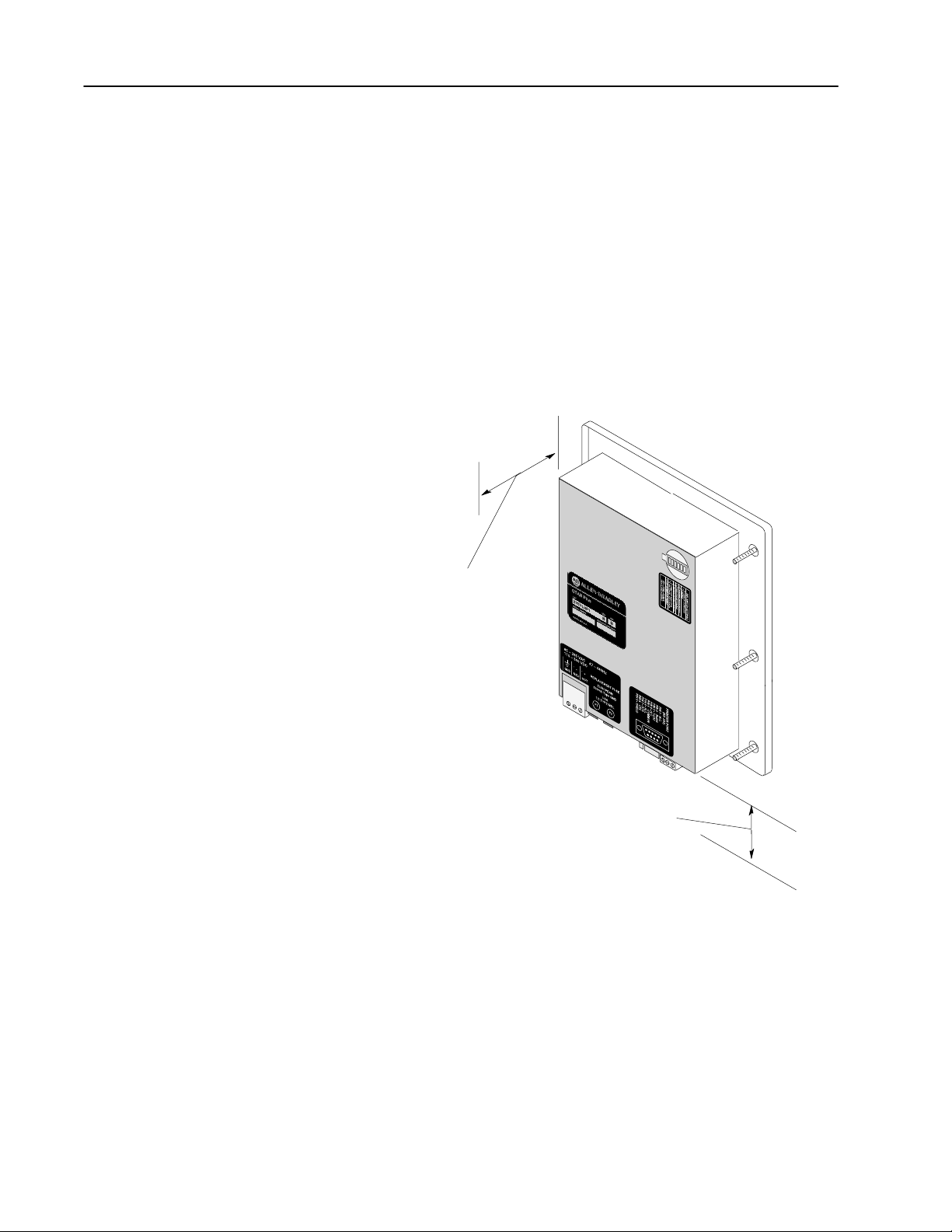
The terminal is tightened against the panel with six self-locking nuts.
Make sure that you leave adequate room, as shown in Figure 1, for
mounting, air flow, cabling and access to DIP switches.
Figure 1
Recommended Clearances
Leave 3 inches (76.2 mm)
for Mounting, Air Flow, and
access to DIP Switches.
Leave 3 inches (76.2 mm) for
communications port connectors.
Page 5
5
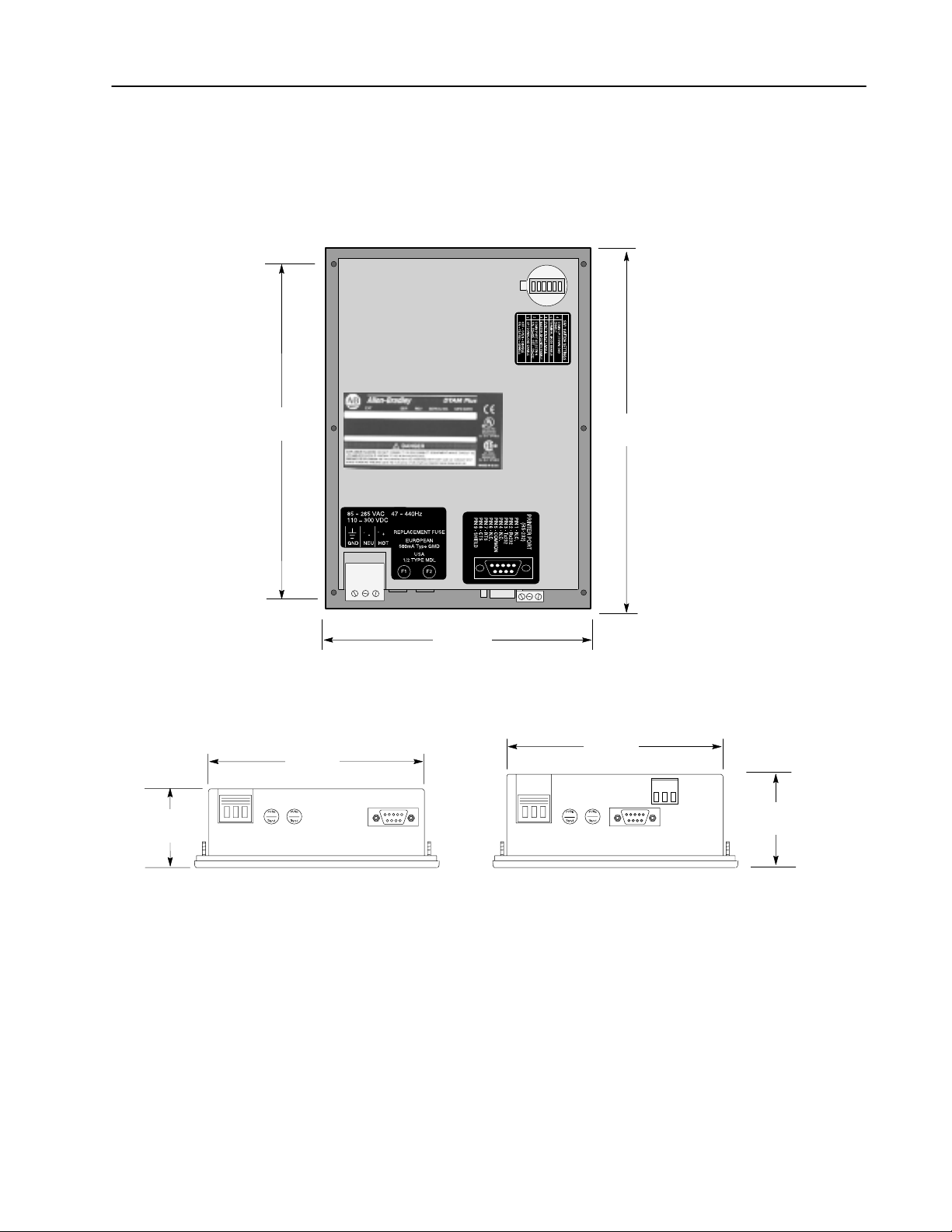
Mounting Dimensions
7.876
(200.1)
Figure 2 shows the mounting dimensions of the terminal.
Figure 2
Mounting Dimensions in Inches (Millimeters)
Back View
8.50
(215.9)
2.0
(50.8)
5.5
(139.7)
6.9
(175.3)
Bottom View
5.5
(139.7)
2.35
(59.7)
Remote I/O and DN VersionsRS-232 / RS-485 Versions
Page 6
6
Installation
To install the DTAM Plus Operator Module:
ATTENTION:
!
1. Using the cutout template shown in Figure 3, cut an opening in
the panel. Remove any sharp edges or burrs.
2. Make sure the sealing gasket is properly positioned on the DTAM
Plus. This gasket forms a compression type seal. Do not use
sealing compounds.
Disconnect all electrical power from the panel before
making cutout.
Make sure that area around panel cutout is clear.
Take precautions so that metal filings or other debris do not
fall into the DTAM Plus ventilation slots or enter any
components that may already be installed in panel.
Make sure that no objects are inserted or fall into the terminal
through the ventilation slots or DIP switch access hole.
Failure to follow these warnings may result in personal injury
or damage to the panel components.
3. Place the DTAM Plus in the panel cutout.
ATTENTION:
!
4. Install the six self locking mounting nuts hand tight.
5. Alternately tighten the mounting nuts until the DTAM Plus is
held firmly against the panel. Tighten mounting nuts to a torque
of 8 to 10 inch-pounds. Do not over-tighten nuts.
Mounting nuts must be tightened to a torque of 8 to 10 inch
pounds to provide a proper seal and to prevent potential
damage to the terminal. Allen-Bradley assumes no
responsibility for water or chemical damage to the terminal or
other equipment within the panel enclosure because of
improper installation.
Page 7

Figure 3
Panel Cutout Dimensions in Inches (Millimeters)
7
Page 8

8
Wire and Cable Length Restrictions
Connecting Power
The following wire and cable length restrictions apply to DTAM
products that are CE marked when used in installations that require
compliance to European EMC Directive 89/336:
DC Power Wiring 10 meters
Ground Terminal Wire 3 meters
Communication Cables 30 meters
These restrictions apply to catalog numbers 2707–L8P1 Series D,
2707–L40P1 Series D and 2707–V40P1 Series D.
The DTAM Plus accepts supply voltages in the following ranges
depending upon the power supply designation.
• Versions with P1 power supply, accept 15-23V AC (47 to 440 Hz)
or 20-30V DC
• Series D versions with P1 Power supply only, accepts 20–30 V
DC
• Versions with P2 power supply, accept 85-265V AC (47 to 440
Hz) or 110-300V DC
• Versions with P4 power supply, accept 11-13V DC
To connect the DTAM Plus to a power source:
ATTENTION: Verify that the power is disconnected from the
power source before wiring. Failure to disconnect power may
!
result in electrical shock.
Make sure that the supply voltage to the DTAM Plus is correct,
refer to the voltage label on back of unit. The incorrect voltage
may damage the DTAM Plus.
Do not overtighten the power connector screw terminals.
Overtightening the terminals may damage the DTAM Plus.
1. Make sure that the voltage source is not turned on.
2. Use AWG#16 or #14 stranded wire to connect the DTAM Plus
screw terminals to the power source (see below).
Note: The power supply terminal block on the DTAM Plus is not
removeable.
Page 9

Figure 4
Power Connections
9
(40K Remote I/O Version Shown, Others Are Similar)
DTAM Plus
For DC connections, connect the Positive Lead
to Hot and the Negative lead to NEU.
3. Connect communications cabling as described in Connecting to
Devices section on page 15.
4. Apply voltage and verify the DTAM Plus powerup sequence as
described in the next section.
Page 10

10
ÎÎÎ
ÎÎÎ
Powerup Sequence
The powerup sequence is automatic. The sequence depends upon the
setting of DIP switch position SW-1 (upload / download enable).
The DTAM Plus is shipped with SW-1 On.
Powerup Sequence (DIP Switch SW-1 ON)
The following steps show the powerup sequence if DIP switch SW-1
is ON.
1. The DTAM Plus verifies the system memory checksum, program
checksum, and system RAM. When done, the result is displayed
with the current DIP switch settings.
Memory Check: pass
DIP Switch: 101000
40K User Memory
2. The display is tested, every pixel of the display is turned on.
Use this display to verify that all pixels are operational.
3. The firmware version number and type of communication port(s)
is displayed (PPort, RS-232, RS-485 or Remote I/O).
Operator Interface
Core: X.XX RS-485
PPORT
4. The DTAM Plus waits for an application download.
Programming Mode
Waiting Up/Download
You cannot operate the DTAM Plus keypad while in the
upload/download mode. The DTAM Plus is waiting for
upload/download operations with a personal computer running
the DTAM Programming Software (DPS).
Page 11

11
Powerup Sequence (DIP Switch SW-1 OFF)
The following steps show the powerup sequence if DIP switch SW-1
is OFF.
1. The DTAM Plus verifies the system memory checksum, program
checksum, and system RAM. After the test is completed, the
result is displayed with the current DIP switch settings.
Checksum: passed
DIP Switch: 001000
RAM: pass
40K User Memory
2. The display is tested, every pixel of the display is turned on.
Use this display to verify that all pixels are operational.
3. The operating system firmware release number and protocol is
displayed (PLC5-DF1 or AB DH-485 or Remote I/O).
Allen-Bradley
Operator Interface
DTAM Plus (c) 1996
FRN: 01.20 AB-RIO
4. On 40K versions with a clock, the current time setting is
displayed.
DATE: W ed Aug 12 98
TIME: 01:12:47
Diagnostics Complete
5. The first application screen displays. When the DTAM Plus is
powered up for the first time you see:
Bul. 2707 DTAM Plus
No Program Loaded
Page 12

12
Upload / Download DIP Switch Settings
Before you can upload or download an application, you must verify
that DIP switch SW-1 is ON. (DTAM Plus is shipped in this
position).
To access the DIP switch, remove the cover from the access hole on
the back of the DTAM Plus (align cover tabs with notches in hole to
remove). The DTAM Plus is shipped without the cover installed,
you can find it in the hardware bag.
On versions with both a Comm and a Printer port, you can transfer
applications using the communication port or the printer port:
• Set DIP switch position SW-6 ON to select the Comm port
• Set DIP switch position SW-6 OFF to select the Printer port
Note: Turn DIP switch SW-6 ON after downloading through the
printer port. This allows communications to occur with the
controller.
All other versions of the DTAM Plus use a single port to transfer
applications; either the Comm port or the Printer port.
If using the Comm port, make sure DIP switch SW-2 is in the correct
position (OFF = RS-232 download, ON = RS-485 download).
Side View
ON =
DIP Switch SW-1
must be ON.
When using the RS-485 / RS-232
Comm Port for file download, set
SW-2 to the correct port selection.
ON = RS-485
OFF = RS-232
123456
OPEN
On Versions with a Printer Port
DIP Switch SW-6 must be:
ON to download using the
Comm port.
OFF to download using the
Printer port (only if the
Comm port is connected to
a host).
Page 13

13
Upload / Download RS-232 Connections
Remote I/O Version With
Printer Port RS-232 Connector
(9 Pin Male)
Gender
Adapter
Cable
(2707-NC2)
T o Computer
RS-232 Port
Comm 1 or 2
Printer Port
Power Connector
Remote I/O Connector
To connect a DTAM Plus RS-232 port to a computer, use the RS-232
Upload/Download cable (Catalog No. 2707-NC2). Use the
communications or printer port (see below). You may need a 9-to-25
pin adapter to connect the cable to your computer. A male to female
gender adapter is required to connect the cable to the printer port or
you can create your own cable. Appendix B of the DTAM Plus User
Manual (2707-UM001B–EN–P).
(T erminal Block)
Remote I/O Version With
Comm Port
Remote I/O Connector
(T erminal Block)
Cable
(2707-NC2)
Power Connector
Comm Port Connector
(9 Pin Female)
To Computer
RS-232 Port
Comm 1 or 2
Versions with a Comm Port Only Versions with a Comm Port
and Printer Port
Cable
(2707-NC2)
Power Connector
Comm Port Connector
(9 Pin Female)
T o Computer
RS-232 Port
Printer Port RS-232 Connector
(9 Pin Male)
Gender
Adapter
Cable
(2707-NC2)
Power Connector
Cable
(2707-NC2)
Comm 1 or 2
T o Computer
RS-232 Port
Comm 1 or 2
Comm Port Connector
(9 Pin Female)
Use Either Port
(Set DIP Switch #6 to
correspond)
Page 14

14
Upload / Download RS-485 Connections
Versions with a Comm Port
Power Connector
RS-485 / RS-232 Connector
(9 Pin Female)
It’s recommended that you use the RS-232 port for transferring
applications. On DTAM Plus versions with a Comm (RS-485 /
RS-232) port, you can also download applications using an RS-485
connection.
Versions with a Comm Port
and Printer Port
Power Connector
Printer Port RS-485 / RS-232 Connector
(9 Pin Female)
Create your own cable
To Computer
RS-485 Port or
Converter
Remote I/O Version With
Comm Port
Remote I/O Connector
(T erminal Block)
Power Connector
RS-485 / RS-232 Connector
(9 Pin Female)
To download through the RS-485 port, you must:
• set DIP switch position SW-2 ON
• create a communication cable. The RS-485 port connections are:
DTAM Plus Comm Port
RS-485/RS-232 Connector
Pin 1 = Tx485 Pin 2 = Tx485 +
Pin 3 = Rx485 Pin 4 = Rx485 +
Page 15

15
Connecting to Devices
To connect the DTAM Plus to an RS-232 device:
1. Make sure that the DTAM Plus is not connected to a voltage source.
2. Use the proper cabling to connect the DTAM Plus Comm port to the
port of the controller (PLC-5 channel 0 or SLC 5/03, 5/04 or 5/05
RS-232 port).
• Use cable, Catalog No. 2707-NC3 for PLC-5 channel 0
connection.
• Use cable, Catalog No. 1747-CP3 for SLC 5/03, 5/04 or 5/05
port connection. This cable requires a 9-pin female to male
gender adapter.
If you need to make your own cable, refer to the cable diagrams in
Appendix B of the DTAM Plus User Manual
(2707–UM001B–EN–P). The maximum recommended cable length
is 50 feet (15.2 meters).
3. Make sure that the communication parameters of the DTAM Plus
match the host device.
4. Apply power and verify that communications are established.
To connect the DTAM Plus terminal to an RS-485 device:
1. Make sure that the power to the DTAM Plus is off.
2. Use the proper cabling to connect the DTAM Plus communications
port to the port of the controller (PLC-5 channel 0 or SLC 5/03, 5/04
or 5/05 RS-232 port).
• Use cable, Catalog No. 2707-NC4 for PLC-5 channel 0
RS-422 connection
• Use cable, Catalog No. 2707-NC5 for PLC-5 channel 0
RS-232 connection. The 2707-NC5 cable converts the signals
from the RS-485 port to RS-232 levels.
• Use cable, Catalog No. 1747-CP3 for SLC 5/03, 5/04 or 5/05
port connection
If you need to make your own cable, refer to the connection
diagrams in Appendix B of the DTAM Plus User Manual
(2707–UM001B–EN–P). The maximum cable length is 200 feet
(60.8 meters).
Important: The DH-485 network cable requires proper shielding,
grounding, and termination. Refer to Data Highway / Data Highway
Plus / Data Highway-485 Cable Installation Manual (1770-6.2.2).
3. The DH-485 connectors are not electrically isolated. If electrical
isolation is required, use Link Couplers (Catalog No. 1747-AIC).
ATTENTION: Electrical isolation using Link Couplers (Catalog
No. 1747-AIC) is required in applications where the distance
!
between the DTAM Plus terminal and the SLC is greater than 6.5
feet (2 meters).
Page 16

16
4. Make sure that the communication parameters of the DTAM Plus
terminal match the host device.
5. Apply power and verify that communications are established.
To connect the DTAM Plus terminal to Remote I/O:
1. Make sure that the power to the DTAM Plus is off.
2. The Remote I/O port of the DTAM Plus provides access via a
Remote I/O link directly to a controller or subscanner. Use cable
(Catalog No. 1770–CD) Belden 9463 for all Remote I/O
connections. Refer to Publication 1770–4.1 for detailed grounding
and wiring guidelines. The User Manual for your controller or
subscanner will also provide cabling instructions.
3. Make sure that the communication parameters of the DTAM Plus
terminal match the host device.
4. Apply power and verify that communications are established.
Page 17

17
DTAM Plus Specifications
Display
Column and Character 4 lines x 20 characters
Display Technology
LCD (2707-L versions) Twisted-nematic type with adjustable
LED (yellow) backlighting
VFD (2707-V versions) Vacuum Fluorescent Display with viewing
distance that exceeds 25 feet (7.6 meters)
Backlight Settings for LCD Version
(via Keypad) Four (0,33,66 and 100%)
Contrast Ratio 10:1
Contrast/Brightness Settings (Keypad)
LCD (2707-L versions) 4 settings
VFD (2707-V versions) 2 settings
Display Size (H x W)
LCD (2707-L versions) 1.0 x 3.0 in (25.2 x 76.0 mm)
VFD (2707-V versions) 1.3 x 3.9 in (33.0 x 99.0 mm)
Character Size (H x W) 0.19 x 0.12 in (4.75 x 2.95 mm)
Keypad
Keypad Type Embossed, sealed membrane
Tactile Feedback Stainless steel dome
Operation Force 12 oz. ± 3 oz. (340 grams ± 85 grams)
Operational Life 1 million cycles
Electrical
Comm Port RS-485 or RS-232C (configurable)
Printer Port (40K memory units) RS-232C
Serial Communication Distances
RS-485 4,000 ft (1219 meters) maximum with the
Link Coupler (Catalog No. 1747-AIC)
RS-232C 50 ft (15 meters) maximum
RS-422 200 ft (61 meters) maximum to a PLC-5
Remote I/O Communication Distances
57.6K 10,000 ft (2800 meters) maximum
115.2K 5,000 ft (1400 meters) maximum
230.4K 2,500 ft (700 meters) maximum
Voltage, Current, Fusing Requirements
Power
Supply
P1 15 - 23V AC, 47 - 440 Hz or 20 - 30V DC 800 mA max. 1 amp
P2 85 - 265V AC, 47 - 440 Hz or 110 - 300V DC 300 mA max. 1/2 amp
P4 11 - 13V DC 250 mA max. 1/2 amp
Port Isolation
Communication Port 500V isolation
Printer Port 500V isolation
Voltage Current Fuse
Page 18

18
Environmental
Ambient Temperature Rating
Operating
LCD Display 0 to
VFD Display 0 to
+45° C (32 to 113° F)
+60° C (32to 140° F)
Storage -20 to +85° C (-4 to 185° F)
Relative Humidity 5 to 95%, noncondensing
Mechanical
Dimensions (Approximate)
Height: 7.6 inch (193.0 mm)
Width: 5.5 inch (139.7 mm)
Depth:
RS-232 / RS 485 Versions 1.8 inch (45.7 mm)
Remote I/O Versions 2.35 inch (59.7 mm)
Front Panel Size:
Height: 8.5 inch (215.9 mm)
Width: 6.5 inch (165.1 mm)
Weight
All except 2707-V40P2N,
-V40P2NR 2.1 lbs (0.95 kg)
2707-V40P2N, -V40P2NR 4.6 lbs (2.09 kg)
Agency Ratings
LED Indicators
RUN LED Green
Alarm LED Red
Function LED Yellow
NEMA Type 4, 12, 13 (indoor use only)
NEMA Type 4X (2707-V40P2N, 2707-V40P2NR only)
Class 1 Division 2 Groups A, B, C, D, hazardous locations
Class 1 Division 2 Groups A, B, C, D, hazardous locations
Class 1 Division 2 Groups C & D, hazardous locations
Temperature Code T3C (2707–L40P4 only)
①
①
Series B or higher – Cat. Nos. 2707–L8P1R, –L8P2R, –L40P1R, –L40P2R,
–V40P1R, –V40P2R, –V40P2NR, –L40P4, –L8P1D, –L8P2D, –L40P1D, –L40P2D,
–V40P1D, –V40P2D, –V40P2ND
Series C or higher – Cat. Nos. 2707–L8P1, –L8P2, –L40P1, –L40P2, –V40P2,
–VP40P1, –VP40P2, –V40P2N
Series D Only – Cat. Nos. 2707–L8P1, –L40P1, –V40P1
①
①
①
Page 19

19
European Union Directive
Compliance
If this product is installed within the European Union or EFTA
regions, the following regulations apply:
This apparatus is tested to meet Council Directive 89/336
Electromagnetic Compatibility (EMC) standards:
• EN50081–2 Class A (Industrial) Emissions
• EN50082–2 Class A (Industrial) Immunity
• EN61000–6–2 Class A (Industrial) Immunity (Series D Only;
2707–L8P1, –L40P1, –V40P1: Series C Only; 2707–L8P2,
–L40P2, –V40P2, V40P2N)
According to these Standards, the factor which determines, for EMC
pruposes, whether an apparatus is deemed to be “Industrial” or
“Residential, commercial and light industrial”, is given in Clause 1
of EN50081–2 as follows:
Apparatus covered by this standard is not intended for
connection to a public mains network, but is intended to be
connected to a power network supplied from a high– or
medium–voltage transformer dedicated for the supply of an
installation feeding a manufacturing or similar plant.
The product described in this document is intended solely for use in
an industrial environment as defined above. When installed in
Europe, any other application is in contravention of the European
Union Directives, and a breach of those laws.
Page 20

Publication 2707-IN005C-EN-P - July 2002 PN 41061-113-01(3)
Supersedes Publication 41061-11 3-01(1) Copyright © 2002 Rockwell Automation. A ll rights reserved. Printed in the U.S.A.
 Loading...