

Page 1
Installation Instructions
InView Communication Modules
Catalog Numbers 2706-PxM, 2706-PxK, 2706-PxP
Topic Page
About This Publication 1
Important User Information 2
Power Supply Requirements 3
Mount the Communication Module to the 2706-P42 and 2706-P44 Displays 3
Wire the Communication Module to the 2706-P42 and 2706-P44 Displays 3
Mount the Communication Module to the 2706-P72 and 2706-P74 Displays 5
Wire the Communication Module to the 2706-P72 and 2706-P74 Displays 6
Mount the Communication Module to the 2706-P92 and 2706-P94 Displays 7
Wire the Communication Module to the 2706-P92 and 2706-P94 Displays 8
Using the Communication Module with a 2706-P22R Display 10
Specifications 11
Additional Resources 11
Configuration Utilities 11
About This Publication
This publication shows how to connect the InView communication module to the
InView display.
Publication 2706-IN015E-EN-P - May 2007
Page 2
2 InView Communication Modules
Important User Information
Solid state equipment has operational characteristics differing from those of electromechanical equipment.
Safety Guidelines for the Application, Installation and Maintenance of Solid State Controls (publication
SGI-1.1 available from your local Rockwell Automation sales office or online at
http://literature.rockwellautomation.com
equipment and hard-wired electromechanical devices. Because of this difference, and also because of the
wide variety of uses for solid state equipment, all persons responsible for applying this equipment must
satisfy themselves that each intended application of this equipment is acceptable.
In no event will Rockwell Automation, Inc. be responsible or liable for indirect or consequential damages
resulting from the use or application of this equipment.
The examples and diagrams in this manual are included solely for illustrative purposes. Because of the many
variables and requirements associated with any particular installation, Rockwell Automation, Inc. cannot
assume responsibility or liability for actual use based on the examples and diagrams.
No patent liability is assumed by Rockwell Automation, Inc. with respect to use of information, circuits,
equipment, or software described in this manual.
Reproduction of the contents of this manual, in whole or in part, without written permission of Rockwell
Automation, Inc., is prohibited.
Throughout this manual, when necessary, we use notes to make you aware of safety considerations.
) describes some important differences between solid state
WARNING
IMPORTANT
ATTENTION
SHOCK HAZARD
BURN HAZARD
Identifies information about practices or circumstances that can cause an explosion in
a hazardous environment, which may lead to personal injury or death, property
damage, or economic loss.
Identifies information that is critical for successful application and understanding of
the product.
Identifies information about practices or circumstances that can lead to personal injury
or death, property damage, or economic loss. Attentions help you to identify a hazard,
avoid a hazard, and recognize the consequences.
Labels may be on or inside the equipment, for example, a drive or motor, to alert
people that dangerous voltage may be present.
Labels may be on or inside the equipment, for example, a drive or motor, to alert
people that surfaces may reach dangerous temperatures.
Publication 2706-IN015E-EN-P - May 2007
Page 3
InView Communication Modules 3
Power Supply Requirements
• The 2706-PxM and 2706-PxK modules are powered by the InView 2706-P4x,
2706-P7x, and 2706-P9x displays.
• The 2706-PxP module requires an external 24V ±25%, 1 A dc power supply
for use with the InView 2706-P22R panel mount display.
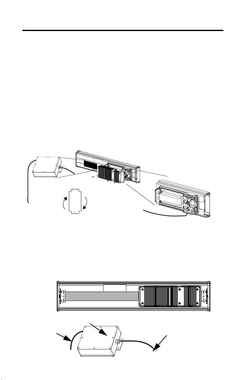
Mount the Communication Module to the 2706-P42 and 2706-P44 Displays
The InView communication module, catalog number 2706-PxM, is designed to
mount to the track of the InView 2706-P42 and 2706-P44 displays. The back plate of
the module has tabs for attaching to the track. Tighten mounting screws until they
bottom out against the back plate.
To T B1
For ease in mounting, rotate
To Controller
(user-supplied
cable)
module 90° so that the
mounting holes are on top and
bottom. Rotate the module
clockwise over track until the
alignment is horizontal.
TB1
Wire the Communication Module to the 2706-P42 and 2706-P44 Displays
Below is an illustration and description of the InView communication module and
its connectors with relation to an InView 2706-P4x display.
Back of InView Display (2706-P42 and 2706-P44)
User-supplied cable
routed through
NEMA-rated cable
grip (supplied).
NEMA Type 12 enclosure with removable cover.
Torque enclosure cover screws to 0.68 Nm (6 lb-in).
2706-PxM
Publication 2706-IN015E-EN-P - May 2007
Serial cable to be connected
to terminal block inside
power supply cover on back
of InView display. Cable to
be routed through cable grip
(supplied).
Page 4
4 InView Communication Modules
1. Disconnect power to the InView display.
ATTENTION
Hazardous voltage. Contact with high voltage may cause death or serious
injury. Always disconnect power to the InView display prior to servicing.
2. Remove the six screws from the power supply cover and remove cover.
Set the screws and cover aside for a later step.
2706-P42 and 2706-P44
Cover Screws
3. Feed the serial cable through the cable grip (shipped with module).
Cover Screws
4. Insert the serial wires through the conduit opening on either the top or the
bottom of the InView display.
TB1 Terminal Block for Serial Connection
Insert the serial wires with
the cable grip into one of
these conduit openings.
Power Line
5. Mount the cable grip to the InView display housing, tighten the locknut
finger-tight, and rotate an additional 1/2 turn.
Publication 2706-IN015E-EN-P - May 2007
Page 5

InView Communication Modules 5
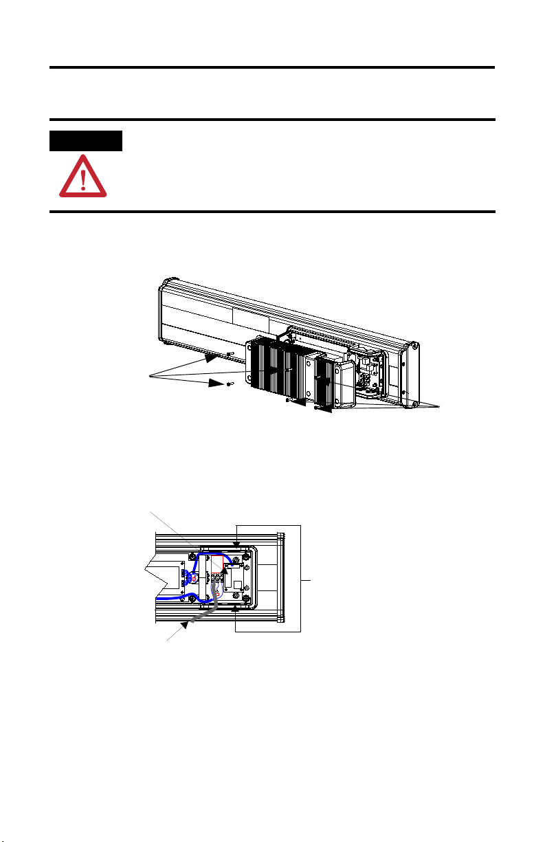
6. Connect the incoming serial wires to the TB1 terminal block.
TIP
TIP
Be sure to place the wires so they are not caught by screws when replacing the
power supply cover and so they do not interfere with fan operation.
TB1
Red (PWR, +5V)2
Incoming
Serial Wires
TB1
Black (GND)1
Orange (TX)3
Brown (RX)4
5
6
7
8
Incoming
Serial Wires
The 2706-PxM communication modules are powered through the serial cable
by the display (series C).
7. Torque the cable grip cap until the cable is securely fastened.
8. Replace the power supply back-cover with the six screws, torquing the
screws to 2.7 Nm (24 lb-in).
9. Connect the power supply to a power source.
Mount the Communication Module to the 2706-P72 and 2706-P74 Displays
The 2706-P72 and 2706-P74 displays are equipped with a mounting plate inside the
case for mounting the 2706-P_K communication kit.
Follow these steps for mounting the communication kit.
ATTENTION
Hazardous voltage. Contact with high voltage may cause death or serious
injury. Always disconnect power to the InView display prior to servicing.
1. Disconnect power to the InView display.
Publication 2706-IN015E-EN-P - May 2007
Page 6

6 InView Communication Modules
2. Open the front of the InView display case by turning the latches counter
clockwise and carefully lowering (opening) the front of the case.
3. Install the communication module to the mounting plate located near the
TB1 terminal block by using the supplied standoffs and screws.
4. Torque the screws to 0.68 Nm (6 lb-in).
TB1
To Controller
(user-supplied
To T B1
cable)
ATTENTION
A label is included in the hardware kit that indicates the default IP address for
the 2706-PENETK EtherNet/IP communication module. The module is shipped
with a default IP address of 192. 168. 1.1. Please consult with personnel who
will be configuring communication for the most appropriate placement of the
label.
Wire the Communication Module to the 2706-P72 and 2706-P74 Displays
The power to the communication module is provided by the InView display
(series C).
Follow these steps for wiring the communcation module.
1. Connect the serial wires to the TB1 terminal block in the InView display.
TB1
Black (GND)1
TIP
Red (PWR, +5V)2
Orange (TX)3
Brown (RX)4
5
6
7
8
The 2706-PxK communication modules are powered through the serial cable by
the display (series C).
Serial Wires
Publication 2706-IN015E-EN-P - May 2007
Page 7

InView Communication Modules 7
2. Route the user-supplied network cable through the cable grip and locknut
that is provided.
3. Connect the user-supplied network cable to the communication module.
4. Verify that there is adequate slack in the cable by making a loop of cable
inside the InView case.
5. Mount the cable grip to the InView display housing, tighten the locknut
finger-tight, and rotate an additional 1/2 turn.
6. Torque the cable grip cap until the cable is securely fastened.
7. Carefully close the InView case and tighten the latches by turning them
clockwise.
8. Connect the InView display to a power source.
Mount the Communication Module to the 2706-P92 and 2706-P94 Displays
The 2706-P92 and 2706-P94 displays are equipped with a mounting plate inside the
case for mounting the 2706-P_K communication module.
Follow these steps for mounting the communication kit.
ATTENTION
Hazardous voltage. Contact with high voltage may cause death or serious
injury. Always disconnect power to the InView display prior to servicing.
1. Disconnect power to the InView display.
2. Open the front of the InView display case by turning the latches
counterclockwise and carefully lowering (opening) the front of the case.
Publication 2706-IN015E-EN-P - May 2007
Page 8

8 InView Communication Modules
3. Install the communication module to the mounting plate located near the
TB1 terminal block by using the supplied standoffs and screws.
4. Torque the screws to 0.68 Nm (6 lb-in).
Communication Module
Front Cover
ATTENTION
A label is included in the hardware kit that indicates the default IP address for
the 2706-PENETK EtherNet/IP communication module. The module is shipped
with a default IP address of 192. 168. 1.1. Please consult with personnel who
will be configuring communication for the most appropriate placement of the
label.
Wire the Communication Module to the 2706-P92 and 2706-P94 Displays
The power to the communication module is provided by the InView display.
Follow these steps for wiring the communcation module.
Publication 2706-IN015E-EN-P - May 2007
Page 9

InView Communication Modules 9
1. Connect the serial wires to the TB2, TB3 terminal block in the InView
display.
Communication Module
TB2 - Aux +5V
+5V (Red) GND (Black)
TB3 - RS-232
TXD (Orange) CTS
RXD (Brown) GND
RTS EGND
TIP
The 2706-PxK communication modules are powered through the serial cable by
the display (series A).
TB2
To TB2 and TB3
TB3
2. Route the user-supplied network cable through the cable grip and locknut
that is provided.
3. Connect the user-supplied network cable to the communication module.
4. Verify that there is adequate slack in the cable by making a loop of cable
inside the InView case.
5. Mount the cable grip to the InView display housing, tighten the locknut
finger-tight, and rotate an additional 1/2 turn.
6. Torque the cable grip cap until the cable is securely fastened.
7. Carefully close the InView case and tighten the latches by turning them
clockwise.
8. Connect the InView display to a power source.
Publication 2706-IN015E-EN-P - May 2007
Page 10

10 InView Communication Modules
1 2 3 4 5
6 7 8 9
RS-232
1 2 3 4 5
6 7 8 9
RS-232
Using the Communication Module with a 2706-P22R Display
The 2706-P22R InView panel-mount display can be used with a 2706-PxP
communication module. The module is mounted on a DIN rail inside the enclosure
in which the 2706-P22R display is mounted. This maintains the NEMA 4x, 12, or 13
rating. The 2706-PxP communication module also requires a separate 24V dc power
supply. This module does not receive power from the InView display.
Follow these steps to mount and connect the communication module.
ATTENTION
Hazardous voltage. Contact with high voltage may cause death or serious
injury. Always disconnect power to the InView display prior to servicing.
1. Disconnect power to the enclosure.
2. Mount the DIN rail somewhere in the enclosure, near the 2706-P22R display.
3. Snap the communication module to the DIN rail and lock the latches.
4. Connect the user-supplied network cable to the communication module.
24V dc
(user-supplied)
DIN Rail
2706-NC13 Serial Cable (supplied)
Publication 2706-IN015E-EN-P - May 2007
Network Port
To Controller
(user-supplied cable)
24V dc
Class 2
24V dc
Page 11

InView Communication Modules 11
5. Connect the communication module to the 2706-P22R display by using the
supplied serial cable.
6. Provide 24V ±25%, 1 A dc to the communication module.
Specifications
InView Communication Module - 2706-PxM, 2706-PxK, 2706-PxP
Attribute Value
Temperature, operating (inside panel) 0…55 °C (32…131 °F)
Temperature, storage -25…70 °C (-13…158 °F)
Humidity (operating and noncondensing) 5…95%
Shock 15 g max pulse operating
Vibration - channel mount 10 Hz < f < 57 Hz 0.012 in. p-p displacement 57 Hz < f 500 Hz 1.0 g
Vibration - DIN rail mount 10 Hz < f < 57 Hz 0.012 in. p-p displacement 57 Hz < f 500 Hz 2.0 g
30 g max pulse nonoperating
Additional Resources
For more information regarding the InView communication module, see these
publications.
Resource Description
InView Communication Module User Manual,
publication 2706-UM017
2706-PSW1 Online Help Details configuration set-up software.
You can view or download publications at
http://literature.rockwellautomation.com
documentation, contact your local Rockwell Automation distributor or sales
representative.
Configuration Utilities
A copy of the utilities to configure the InView communication modules is included
on the InView Messaging Software CD, version 1.3 or later (catalog number
2706-PSW1).
Provides information about the InView
communication module.
. To order paper copies of technical
Publication 2706-IN015E-EN-P - May 2007
Page 12

Rockwell Automation Support
Rockwell Automation provides tec hnical information on the Web to assist you in using its products.
At http://www.rockwellautomation.com/support
service packs. You can also visit our Support Center at https://rockwellautomation.custhelp.com/
and forums, technical information, FAQs, and to sign up for product notification updates.
In addition, we offer multiple support programs for installation, configuration, and troubleshooting. For more information, contact
your local distributor or Rockwell Automation representative, or visit http://www.rockwellautomation.com/services/online-phone
Installation Assistance
If you experience a problem within the first 24 hours of installation, please review the information that's contained in this manual.
You can also contact a special Customer Support number for initial help in getting your product up and running.
United States or Canada 1.440.646.3434
Outside United States or
Canada
Use the Wor ldwi de Loc ator
http://www.rockwellautomation.com/rockwellautomation/support/overview.page
local Rockwell Automation representative.
New Product Satisfaction Return
Rockwell Automation tests all of its products to help ensure that they are fully operational when shipped from the manufacturing
facility. However, if your product is not functioning and needs to be returned, follow these procedures.
you can find technical and application notes, sample code, and links to software
for software updates, support chats
at
, or contact your
.
United States
Outside United States Please contact your local Rockwell Automation representative for the return procedure.
Contact your distributor. You must provide a Customer Support case number (call the phone number
above to obtain one) to your distributor to complete the return process.
Documentation Feedback
Your comments will help us serve your documentation needs better. If you have any suggestions on how to improve this document,
complete this form, publication RA-DU002
Rockwell Automation maintains current product environmental information on its website at
http://www.rockwellautomation.com/rockwellautomation/about-us/sustainability-ethics/product-environmental-compliance.page
Allen-Bradley, InView, and Rockwell Automation are trademarks of Rockwell Automation, Inc.
Trademarks not belonging to Rockwell Automation are property of their respective companies.
Rockwell Otomasyon Ticaret A.Ş., Kar Plaza İş Merkezi E Blok Kat:6 34752 İçerenköy, İstanbul, Tel: +90 (216) 5698400
Publication 2706-IN015E-EN-P - May 2007 PN-19616
Supersedes Publication 2706-IN015D-MU-P - April 2004 Copyright © 2007 Rockwell Automation, Inc. All rights reserved. Printed in the U.S.A.
, available at http://www.rockwellautomation.com/literature/.
.
 Loading...