

Rockwell Automation 2706-PRIO, 2706-PDH485, 2706-PDHP, 2706-PDNET, 2706-PCNET User Manual
...Page 1

InView
Communications
2706-PRIO, 2706-PDH485,
2706-PDHP, 2706-PDNET,
2706-PCNET, 2706-PENET,
2706-PENET1
User Manual
Page 2
Important User Information
Solid state equipment has operational characteristics differing from those of
electromechanical equipment. Safety Guidelines for the Application,
Installation and Maintenance of Solid State Controls (publication SGI-1.1
available from your local Rockwell Automation sales office or online at
http://literature.rockwellautomation.com
differences between solid state equipment and hard-wired electromechanical
devices. Because of this difference, and also because of the wide variety of
uses for solid state equipment, all persons responsible for applying this
equipment must satisfy themselves that each intended application of this
equipment is acceptable.
In no event will Rockwell Automation, Inc. be responsible or liable for
indirect or consequential damages resulting from the use or application of
this equipment.
The examples and diagrams in this manual are included solely for illustrative
purposes. Because of the many variables and requirements associated with
any particular installation, Rockwell Automation, Inc. cannot assume
responsibility or liability for actual use based on the examples and diagrams.
No patent liability is assumed by Rockwell Automation, Inc. with respect to
use of information, circuits, equipment, or software described in this manual.
Reproduction of the contents of this manual, in whole or in part, without
written permission of Rockwell Automation, Inc., is prohibited.
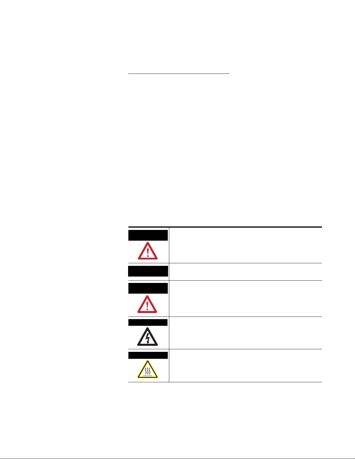
Throughout this manual, when necessary, we use notes to make you aware
of safety considerations.
) describes some important
WARNING
IMPORTANT
ATTENTION
SHOCK HAZARD
BURN HAZARD
Identifies information about practices or circumstances that can cause
an explosion in a hazardous environment, which may lead to personal
injury or death, property damage, or economic loss.
Identifies information that is critical for successful application and
understanding of the product.
Identifies information about practices or circumstances that can lead
to personal injury or death, property damage, or economic loss.
Attentions help you identify a hazard, avoid a hazard, and recognize
the consequence
Labels may be located on or inside the equipment, for example, a drive
or motor, to alert people that dangerous voltage may be present.
Labels may be located on or inside the equipment, for example, a drive
or motor, to alert people that surfaces may be dangerous
temperatures.
Page 3

Summary of Changes
This document describes the InView Communication Module.
Revision bars in the margin identify updated information. Changes for
this version of the document include:
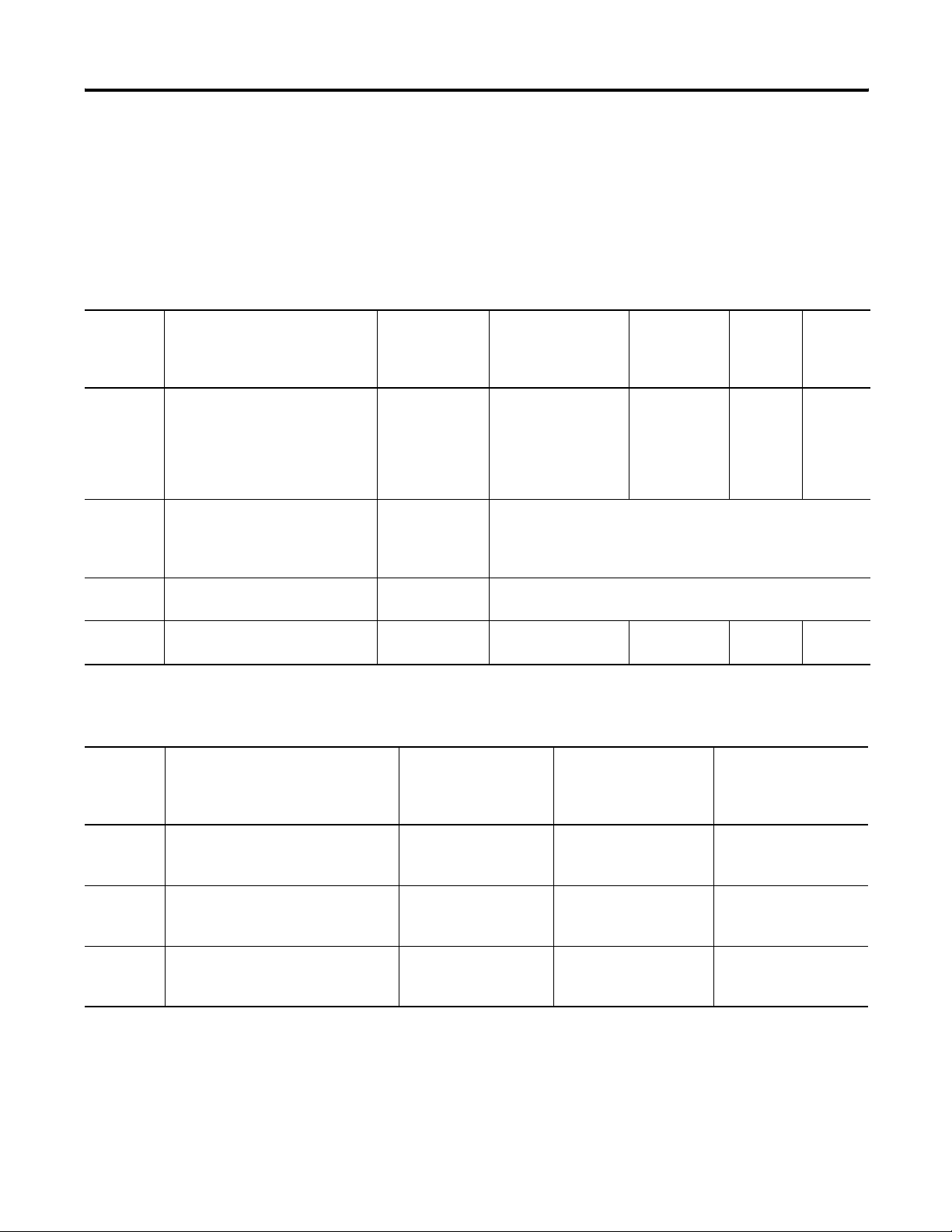
Change Page
Added a note that communication modules should be
configured serially before it is mounted to the display
1-5
Added that the communication utility creates files with the
extension of .ivc which is different from InView message
files which have the extension of .ivp
Added a note for the user to check the InView web pages for
new or updated information
Added a note that communication modules should be
configured serially before it is mounted to the display
Removed appendix with InView labs Appendix A
1-7
4-1
4-28
1 Publication 2706-UM017C-EN-P - March 2006
Page 4

2 Summary of Changes
Publication 2706-UM017C-EN-P - March 2006
Page 5

Introduction to InView
Connectivity
Install InView Communication
Modules
InView Communication Module
Connections
Table of Contents
Chapter 1
Controller Based Communications . . . . . . . . . . . . . . . . . . . 1-2
PC Based Communications . . . . . . . . . . . . . . . . . . . . . . . . 1-3
Set the 2706-PENET1 IP Address . . . . . . . . . . . . . . . . . . . . 1-5
Create a New InView Network Communication Application 1-7
Chapter 2
Mount Module to 2706-P42, 2706-P43 and
2706-P44 Displays . . . . . . . . . . . . . . . . . . . . . . . . . . . . . . . 2-1
Wire Communication Module to InView Display 2706-P42,
2706-P43, 2706-P44 . . . . . . . . . . . . . . . . . . . . . . . . . . . . . . 2-1
Mount Communication Kit to 2706-P72, 2706-P74,
2706-P92 and 2706-P94 Displays . . . . . . . . . . . . . . . . . . . . 2-3
Wire Communication Kit to 2706-P72, 2706-P74,
2706-P92 and 2706-P94 Displays . . . . . . . . . . . . . . . . . . . . 2-4
Use Communication Module with a 2706-P22R Display. . . . 2-5
Chapter 3
Chapter Objectives . . . . . . . . . . . . . . . . . . . . . . . . . . . . . . 3-1
Wire and Safety Guidelines . . . . . . . . . . . . . . . . . . . . . . . . 3-1
Cable Tables. . . . . . . . . . . . . . . . . . . . . . . . . . . . . . . . . . . 3-2
Remote I/O Connections . . . . . . . . . . . . . . . . . . . . . . . . . . 3-4
DH+ Connections . . . . . . . . . . . . . . . . . . . . . . . . . . . . . . . 3-8
DH-485 Terminal Connections. . . . . . . . . . . . . . . . . . . . . . 3-11
ControlNet Connections . . . . . . . . . . . . . . . . . . . . . . . . . . 3-17
DeviceNet Connections . . . . . . . . . . . . . . . . . . . . . . . . . . . 3-21
EtherNet/IP Connections . . . . . . . . . . . . . . . . . . . . . . . . . . 3-24
Connect a Computer . . . . . . . . . . . . . . . . . . . . . . . . . . . . . 3-26
Chapter 4
Application Guide
ControlNet Communication and Tag Setup Screens. . . . . . . 4-1
DeviceNet Communication and Tag Setup Screens . . . . . . . 4-6
Data Highway Plus (DHP) Communication and Tag Setup
Screens. . . . . . . . . . . . . . . . . . . . . . . . . . . . . . . . . . . . . . . 4-16
DH485 Communication and Tag Setup Screens . . . . . . . . . 4-23
EtherNet Communication and Tag Setup Screens . . . . . . . . 4-28
RIO Communication and Tag Setup Screens. . . . . . . . . . . . 4-41
Save or Download an Application File . . . . . . . . . . . . . . . . 4-50
Chapter 5
InView Communication Module
Troubleshooting
i Publication 2706-UM017C-EN-P - March 2006
Chapter Objectives . . . . . . . . . . . . . . . . . . . . . . . . . . . . . . 5-1
Equipment Required . . . . . . . . . . . . . . . . . . . . . . . . . . . . . 5-1
Use the Troubleshooting Table . . . . . . . . . . . . . . . . . . . . . 5-1
Indicators . . . . . . . . . . . . . . . . . . . . . . . . . . . . . . . . . . . . . 5-4
Page 6

ii Table of Contents
InView Communication Module
Specifications
Appendix A
Communication Specifications . . . . . . . . . . . . . . . . . . . . . . A-1
Power Supply Requirements . . . . . . . . . . . . . . . . . . . . . . . A-1
Index
Publication 2706-UM017C-EN-P - March 2006
Page 7
Chapter
1
Introduction to InView Connectivity
InView message displays come standard with RS-232 and RS-485
communications for quick and easy integration. For applications
requiring industrial or commercial networks, InView communications
modules can be used to integrate your display into new and existing
networks.
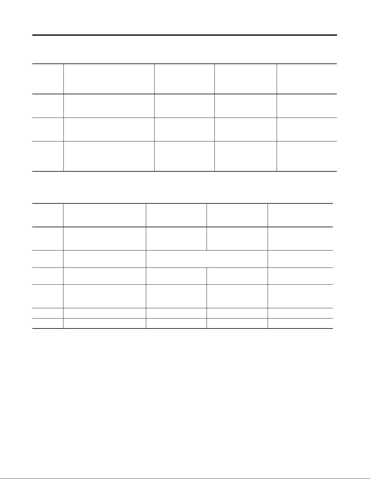
InView Communication Option
Network Communication Module
2706-P22R 2706-P42R, -P42C,
-P43R, -P43C,
-P44R, -P44C
Remote I/O 2706-PRIOP 2706-PRIOM 2706-PRIOK
2706-P72CN2,
-P74CN2,
-P72CN1, -P74CN1
DH-485 2706-PDH485P 2706-PDH485M 2706-PDH485K
DH+ 2706-PDHPP 2706-PDHPM 2706-PDHPK
DeviceNet 2706-PDNETP 2706-PDNETM 2706-PDNETK
ControlNet 2706-PCNETP 2706-PCNETM 2706-PCNETK
EtherNet IP 2706-PENETP 2706-PENETM 2706-PENETK
Ethernet TCP/IP
(1)
Rockwell Automation recommends using a third party DIN rail mounted Ethernet TCP/IP solution with the
InView P22R panel mount display. Lantronixs and Digi both supply a DIN rail Ethernet TCP/IP solution for
connectivity to a personal computer.
(1)
2706-PENET1
1 Publication 2706-UM017C-EN-P - March 2006
Page 8
1-2 Introduction to InView Connectivity
Controller Based Communications
InView controller based communication can be used to trigger
messages and update variables on an InView display. InView
communication allows for connection into new and existing control
environments.
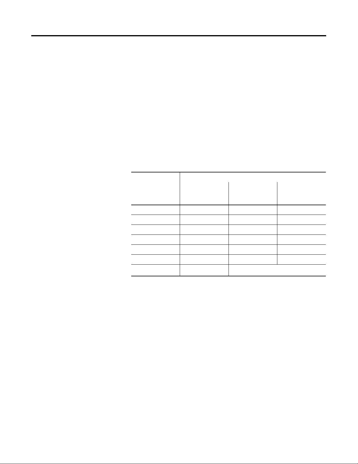
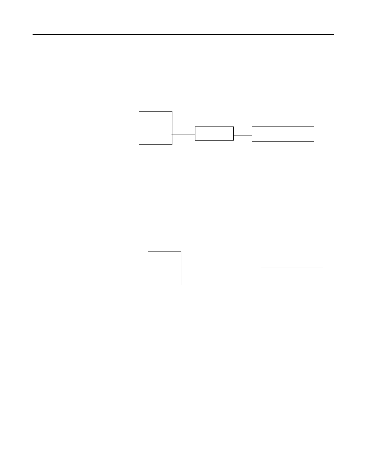
Point-to-point RS-232 Serial Communications
Point-to-point serial communications allow the use of a controller to
trigger messages and update variables on an InView display. RS-232
serial communications support a single display connection with a
limited distance of 15.24 m (50 ft).
RS-232 Serial Communications
CH.0
RS-232
InView Display
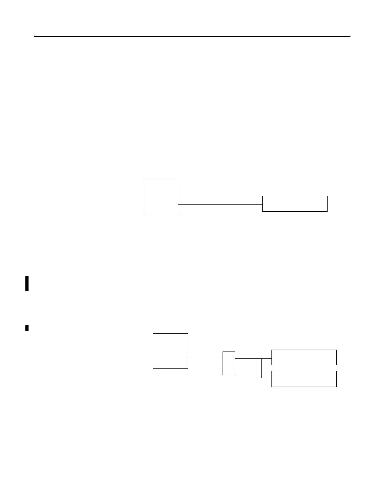
Multi-drop RS-485 Serial Communications
RS-485 Multi-drop networks allow for Serial communications from a
single controller to multiple InView displays. With the use of an AIC+
(RS-232 to RS-485 converter) or a 2706-P9 type InView display, you
can daisy chain multiple InView displays off channel zero of an
Allen-Bradley controller. Each InView display can have a unique
address, allowing for individual display control over the network with
a maximum distance of 1219 m (4000 ft).
RS-485 Serial Communications
CH.0
RS-232
AIC+ or a
2706-P9 type
InView Display
RS-485
InView Display
InView Display
Publication 2706-UM017C-EN-P - March 2006
Page 9
Introduction to InView Connectivity 1-3
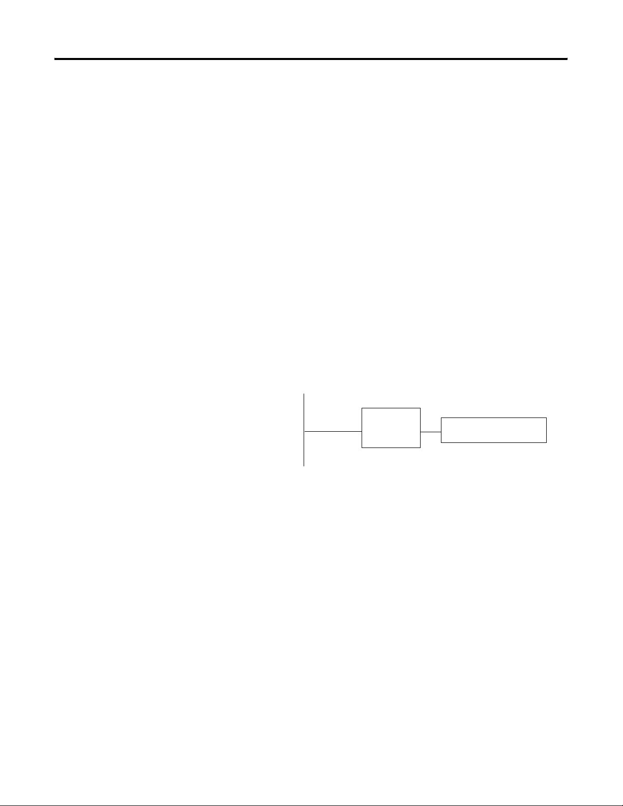
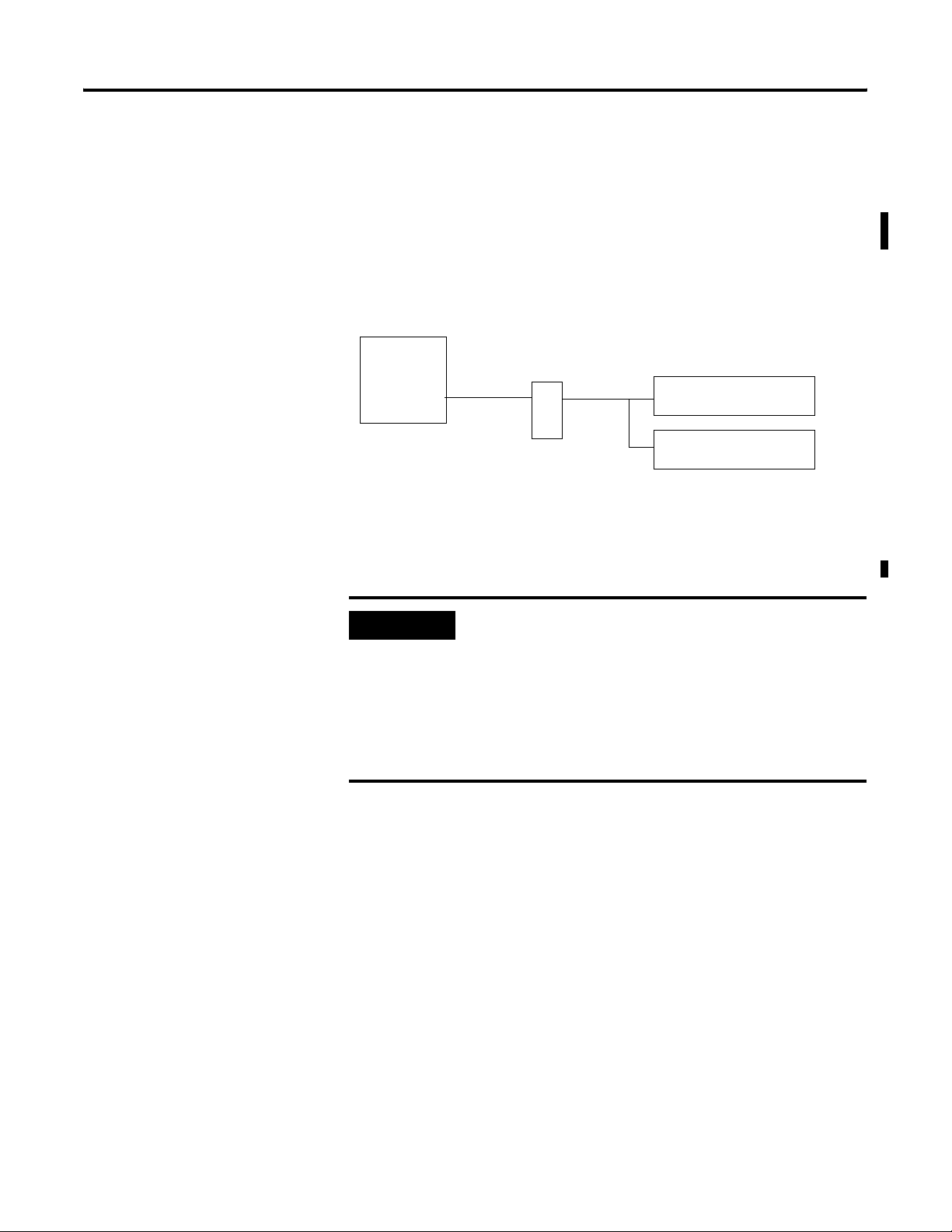
Industrial Network Communications
InView communication modules allow InView displays to
communicate with controllers over the following networks.
• Data Highway Plus
• DH-485
• Remote I/O
• DeviceNet
• ControlNet
• Ethernet
The InView communication modules take controller based
communications one step farther. They allow InView message
displays to communicate on the core Allen Bradley networks. The
InView software includes a communication utility to set up the tags in
the communication module to correspond to a controller’s data tables.
The data tables within a controller are used to trigger messages and or
update variables.
PC Based Communications
Industrial Network Communications
Industrial
Network
InView
Communication
Module
InView Display
InView PC based communications can be used to download message
files and trigger message/update variables on your InView display.
This can be done using the InView messaging software, the Instant
Messenger, or via the InView ActiveX control added to a VBA project
or container. The InView messaging software allows for the creation,
downloading and triggering of messages, where the Instant Messenger
software is more suited for triggering the message. The ActiveX
control allows custom applications to be created using a VBA
environment such as RSView32. This allows for the most flexibility
and functionality when creating an application to drive an InView.
Ethernet TCP/IP
InView Ethernet TCP/IP communication modules let you integrate
your displays into Information System and Supervisor Control PC
based systems. Ethernet TCP/IP communications let you make use of
Publication 2706-UM017C-EN-P - March 2006
Page 10
1-4 Introduction to InView Connectivity
your existing office network to communicate information to the entire
factory.
See publication 2706-IN008, for information on installing and setting
up Ethernet TCP/IP.
PC
EtherNet TCP/IP
TCP/IP Module
2706-PENET1
InView Display
Serial RS-232 Communications
PC based RS-232 connection to communicate to an InView display.
This is done via the InView messaging software, Instant Messenger, or
the ActiveX control in RSView32 software. This is effective for a single
display located 15.24 m (50 ft) from the PC or when downloading
message applications.
PC
RS-232
InView Display
Publication 2706-UM017C-EN-P - March 2006
Page 11
Introduction to InView Connectivity 1-5
Serial RS-485 Communications
PC based RS-485 serial networks. For multi-drop connection to an
InView display, an AIC+ (RS-232 to RS-485 converter) or a 2706-P9
type InView display can be used off the PC comm port. This allows
individual control of multiple displays on a single network up to
1219 m (4000 ft).
Set the 2706-PENET1 IP Address
PC
IMPORTANT
RS-232
AIC+ or a
2706-P9 type
InView display
The Ethernet communications modules should be
RS-485
configured serially before mounting to the InView
display or hanging/mounting the display in a high or
remote location. Communication modules require an
initial setup to establish node or IP address before
being able to function on a network. The serial
configuration requires a 2706-NC13 cable and the
InView message software.
To set the 2706-PENET1 IP address:
InView Display
InView Display
1. Open the InView software.
2. Add a display to the project.
3. Under the display management portion of the interface, right
click the display to add and click Edit Display.
The Edit Display dialog opens.
Publication 2706-UM017C-EN-P - March 2006
Page 12
1-6 Introduction to InView Connectivity
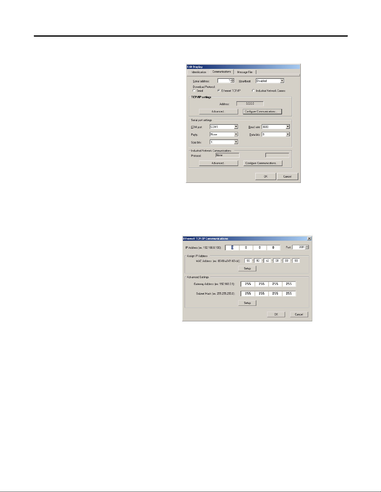
4. Navigate to the Communications tab.
5. Assure Ethernet TCP/IP is selected under the Download
Protocol.
6. Click the Configure Communications button to set the IP
Address.
The Ethernet TCP/IP Communications Configuration dialog
opens.
7. Enter IP Address desired, the MAC Address and click Setup.
• MAC ID is case sensitive
• The PC being used to set the IP should be on the same subnet
and should be in the same range of IP addresses as the
2706-PENET1.
Publication 2706-UM017C-EN-P - March 2006
Page 13
Introduction to InView Connectivity 1-7
Create a New InView Network Communication Application
The communication utility allows the InView message display to be
configured to communicate with an Allen-Bradley controller over an
industrial network. The communication utility creates a file of
extension .ivc, which you can save, reuse, or edit. This is separate
from InView message files, which is of extension .ivp.
All communication and tag parameters are configured from a common
dialog. Your configuration is saved to an .ivc file for later use or
editing.
To create a new InView network communication application:
1. Open the InView software.
2. Add a display to the project.
3. Under the display management portion of the interface, right
click the display to add and click Edit Display.
The Edit Display dialog opens.
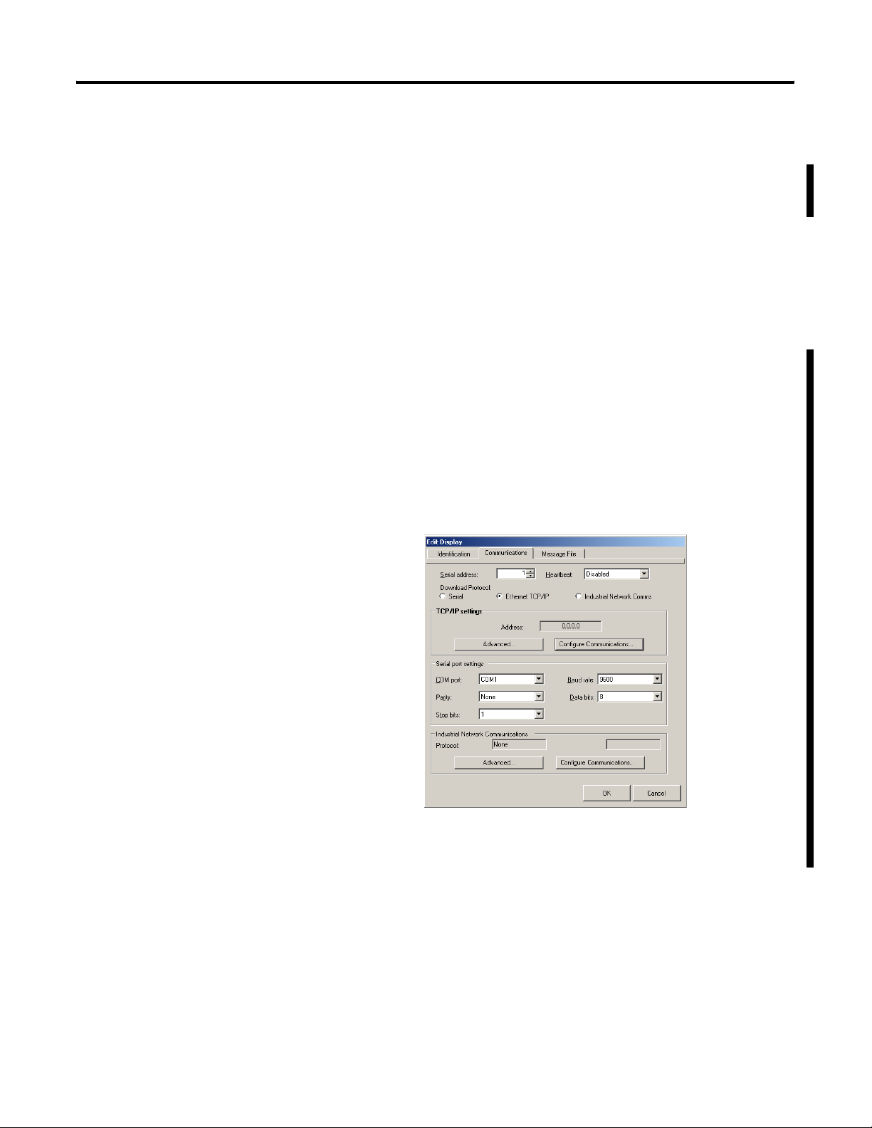
4. Navigate to the Communications tab.
5. Assure Industrial Network Communications is selected under the
download protocol.
Publication 2706-UM017C-EN-P - March 2006
Page 14
1-8 Introduction to InView Connectivity
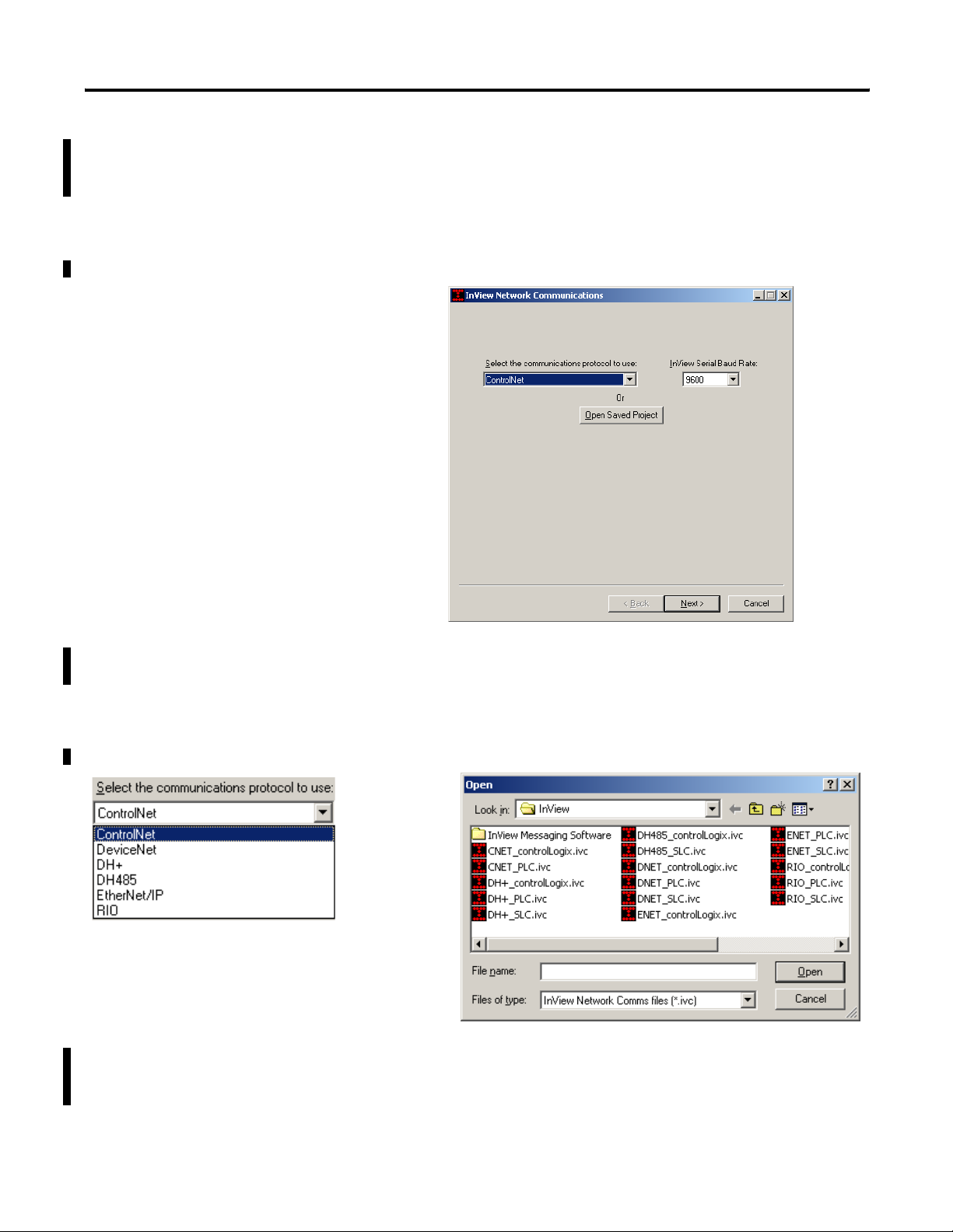
6. Click the configure communications button in the Industrial
Networks Communications section on the bottom of the
communications tab.
The following dialog appears.
7. Select a communication protocol or click the Open Saved
Project button to open a previously saved .ivc configuration file.
Either dialog appears.
or
A saved InView Network Communications file (*.ivc) can still be
edited within the utility and either downloaded to the
communication module or saved.
Publication 2706-UM017C-EN-P - March 2006
Page 15

Introduction to InView Connectivity 1-9
8. If creating a new InView network communications file, select a
protocol from the list. Then, choose an InView serial
communication rate.
This is the communication rate that the communication module
and the InView display communicate at.
Currently all InView displays communicate at 9600 bps, with the
exception of the 2706-P92 and 2706-P94 displays. Those can
communicate at either 9600 bps or 19200 bps.
9. Setup the communication and tag setup screens dependent
upon the protocol and type of controller.
How to setup the communication and tag setup screens is
described in Chapter 4.
Publication 2706-UM017C-EN-P - March 2006
Page 16

1-10 Introduction to InView Connectivity
Publication 2706-UM017C-EN-P - March 2006
Page 17
Chapter
Install InView Communication Modules
2
Mount Module to 2706-P42, 2706-P43 and 2706-P44 Displays
To T B 1
To Controller
(Customer Supplied
Cable)
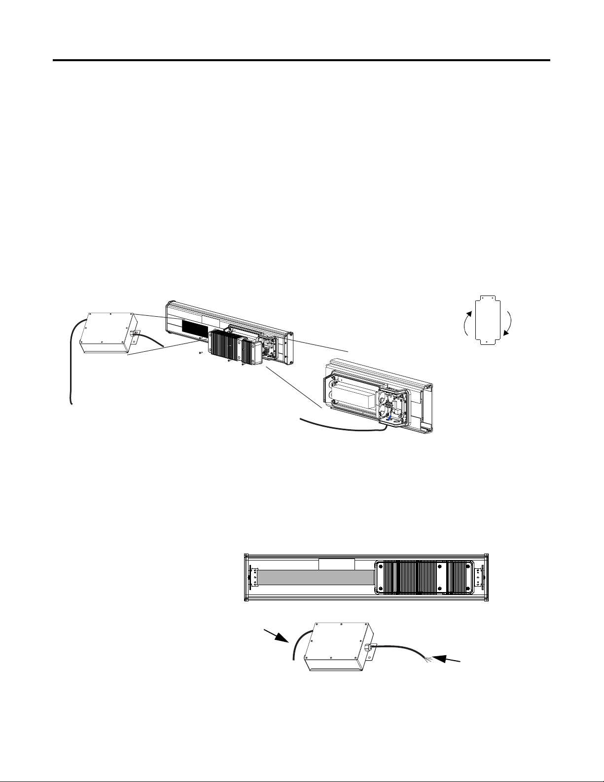
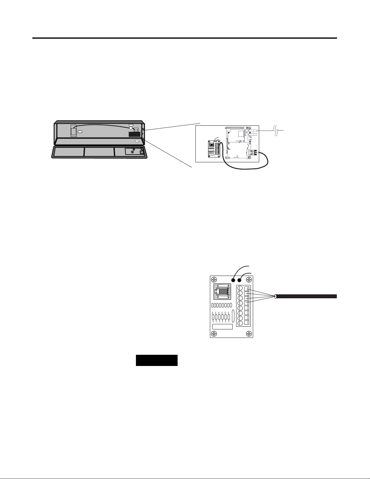
The InView communication module is designed to mount to the track
of the InView 2706-P42, 2706-P43 and 2706-P44 displays.
1. Align the tabs on the back plate of the module to the track on
the display.
2. Tighten mounting screws until they bottom out against the back
plate.
For ease in mounting, rotate
module 90° so that the
mounting holes are on top and
bottom. Rotate the module
clockwise over track until the
alignment is horizontal.
TB1
Wire Communication
Module to InView Display
Below is an illustration and description of the InView communication
module and its connectors with relation to an InView 2706-P4x
display.
2706-P42, 2706-P43,
2706-P44
Customer-supplied cable
through NEMA-rated cable
grip (supplied)
1 Publication 2706-UM017C-EN-P - March 2006
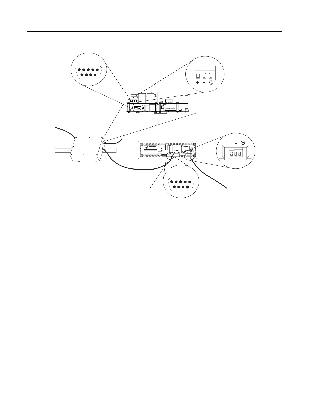
Wire Communication Module to InView Display
Back of InView Display (P42, P43, P44)
2706-P_M
NEMA Type 12 Enclosure with Removable Cover
Torque Enclosure Cover screws to 0.68 Nm (6 in-lb).
Serial cable to be
connected to terminal
block inside power supply
cover on back of InView
display. Cable to be
routed through cable grip
(supplied).
Page 18
2-2 Install InView Communication Modules
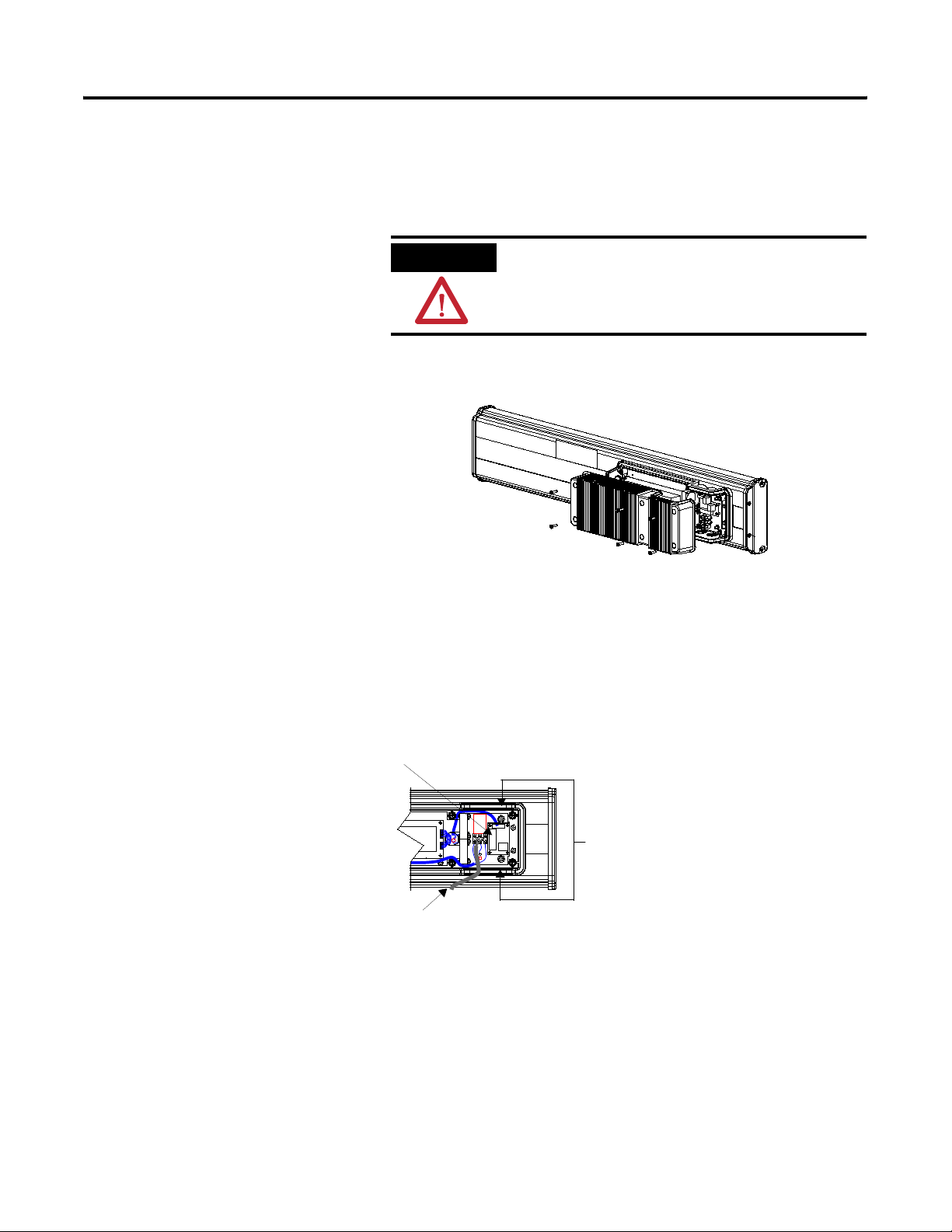
To wire the communication module to the InView display:
1. Disconnect power to InView display.
ATTENTION
Hazardous voltage. Contact with high voltage
may cause death or serious injury. Always
disconnect power to the InView display prior
to servicing.
2. Remove six screws on the power supply cover (on 2706-P4x).
2706-P42, 2706-P43, 2706-P44
3. Route the serial cable through the cable grip (shipped with
module).
4. Insert the serial wires through the conduit opening on either the
top or the bottom of the InView display.
TB1 Terminal Block for serial connection
Publication 2706-UM017C-EN-P - March 2006
Insert the serial wires
with the cable grip into
one of these conduit
openings.
Power Line
5. Mount the cable grip to the InView display housing.
6. Tighten the locknut finger-tight and rotate an additional 1/2
turn.
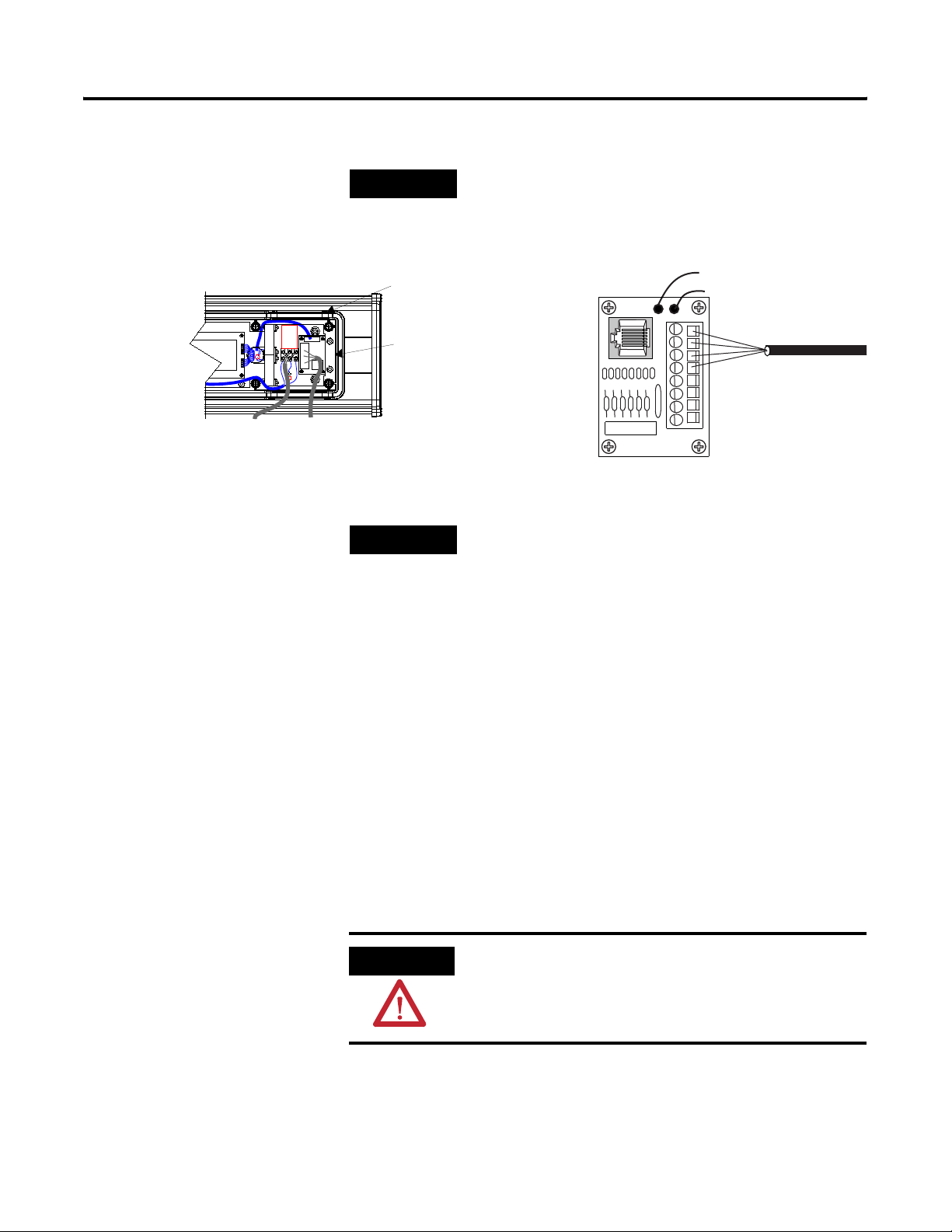
7. Connect the incoming serial wires to the TB1 terminal block.
Page 19
Install InView Communication Modules 2-3
TIP
Be sure to place the wires so they are not caught by
screws when replacing the power supply cover, and
also so they do not interfere with fan operation.
TB1
Incoming
serial wires
TIP
TB1
Black (GND)1
Red (PWR, +5V)2
Orange (TX)3
Brown (RX)4
5
6
7
8
The 2706-P_M communication modules are powered
through the serial cable by the display (Series C).
8. Tighten the cable grip cap until the cable is securely fastened.
Mount Communication Kit to 2706-P72, 2706-P74, 2706-P92 and 2706-P94 Displays
9. Replace the power supply back cover with the 6 screws (on
2706-P4x).
10. Torque the screws to 2.7Nm (24 in-lbs).
11. Connect the power supply to a power source.
The 2706-P72, 2706-P74, 2706-P92 and 2706-P94 displays are
equipped with a mounting plate inside the case for mounting the
Communication Kit.
ATTENTION
Hazardous Voltage. Contact with high voltage may
cause death or serious injury. Always disconnect
power to the InView display prior to servicing.
To mount the communication module to the InView display:
1. Disconnect power to the InView display.
Publication 2706-UM017C-EN-P - March 2006
Page 20
2-4 Install InView Communication Modules
2. Open the front of the InView case by turning the latches counter
clockwise and carefully lower the front of the case.
3. Install the Communication Kit (2706-P_K) to the mounting plate
located near TB1 using the supplied standoffs and screws.
4. Torque the screws to 0.68 Nm (6 in-lbs).
To Controller
TB1
(Customer Supplied
Cable)
To T B 1
Wire Communication Kit to 2706-P72, 2706-P74, 2706-P92 and 2706-P94 Displays
The power to the communication module is provided by the InView
display (series C).
To wire the communication module to the InView display:
1. Connect the serial wires to the TB1 terminal block in the InView
display.
Black (GND)1
Red (PWR, +5V)2
Orange (TX)3
TIP
Brown (RX)4
The 2706-P_K communication kits are powered
through the serial cable by the display (series C).
5
6
7
8
Publication 2706-UM017C-EN-P - March 2006
2. Route the customer supplied network cable through the cable
grip and locknut that is provided.
3. Connect the customer supplied network cable to the
Communication Kit.
Verify that there is adequate slack in the cable by making a loop
of cable inside the InView case.
Page 21

Install InView Communication Modules 2-5
4. Mount the cable grip to the InView display housing.
5. Tighten the locknut finger-tight and rotate an additional 1/2
turn.
6. Tighten the cable grip cap until the cable is securely fastened.
7. Carefully close the InView case and tighten the latches by
turning them clockwise.
8. Connect the InView to a power source.
Use Communication Module with a 2706-P22R Display
The 2706-P22R InView panel mount display can be used with a
2706-P_P communication module. The module is mounted on a DIN
rail inside the enclosure the 2706-P22R display is mounted. This
maintains the NEMA 4x, 12 or 13 rating. The 2706-P_P communication
module also requires a separate 24V dc power supply. This module
does not receive power from the InView display.
To use the communication module with the InView display:
1. Disconnect power to the enclosure.
2. Mount DIN rail somewhere in the enclosure, near the 2706-P22R
display.
3. Snap the communication module to the DIN rail, and lock the
latches.
4. Connect the customer supplied network cable to the
communication module.
Publication 2706-UM017C-EN-P - March 2006
Page 22
2-6 Install InView Communication Modules
RS-232
1 2 3 4 5
6 7 8 9
24V dc
(Customer Supplied)
DIN Rail
To Controller (Customer Supplied Cable)
24V dc
2706-NC13 Serial Cable
(Supplied)
Network Port
RS-232
1 2 3 4 5
6 7 8 9
Class 2
24V dc
5. Connect the communications module to the 2706-P22R display
by using the supplied serial cable.
6. Provide 24 volts ±25 percent, 1A DC to the communications
module.
Publication 2706-UM017C-EN-P - March 2006
Page 23
Chapter
3
InView Communication Module Connections
Chapter Objectives
Wire and Safety Guidelines
This chapter describes network and device connections for InView
communication modules.
• Wire and Safety Guidelines
• Cable Tables
• Remote I/O Connections
• DH+ Connections
• DH-485 Terminal Connections
• ControlNet Connections
• DeviceNet Connections
• EtherNet/IP Connections
• Connect a Computer
Use Electrical Safety Requirements for Employee Workplaces,
publication NFPA 70E, when you wire the InView communication
module. Also, consider these guidelines.
• Route communication cables to terminal by a separate path from
incoming power
IMPORTANT
• Where power and communication lines must cross, they should
cross at right angles. Communication lines can be installed in the
same conduit as low level DC I/O lines (less than 10 volts)
• Grounding minimizes noise from Electromagnetic Interference
(EMI) and is a safety measure in electrical installations
• Use the National Electric Code published by the National Fire
Protection Association as a source for grounding
WARNING
1 Publication 2706-UM017C-EN-P - March 2006
Do not run signal wiring and power wiring
in the same conduit.
EXPLOSION HAZARD
Do not connect or disconnect equipment unless
power has been switched off and area is known to
be non-hazardous.
Page 24
3-2 InView Communication Module Connections
Cable Tables
Refer to the following tables for a summary of InView communication
module connections to controllers and network interface modules.
Runtime Communication Cables - To Processors
InView to SLC
Protocol InView Standard Comm Port SLC-500, 5/01,
5/02
CH1 RJ45
(DH-485)
DH-485 DH-485 Communication Port (RJ45) 1747-C10
(2m/6ft)
1747-C11
(0.3m/1ft)
1747-C20
(6m/20ft)
DeviceNet DeviceNet Communication Port to SLC 5/02
with 1747-SDN
and
DeviceNet cable
ControlNet ControlNet Communication Port N/A not applicable - InView communication module does not support
SLC-5/03, 5/04, 5/05
CH0 (9-pin RS-232)
(DF1 or DH-485)
use AIC+ Module
(1761-NET-AIC)
Connect to Port 3
use 1747-SDN Module with DeviceNet cable
SLC ControlNet configurations
SLC 5/03
CH1 (RJ45)
(DH-485)
1747-C10
(2m/6ft)
1747-C11
(0.3m/1ft)
1747-C20
(6m/20ft)
SLC 5/04
CH1
(DH+)
N/A N/A
SLC 5/05
CH1
(ENET)
EtherNet/IP Ethernet Comm Port N/A N/A N/A N/A Ethernet
cable
InView to PLC-5, ControlLogix, MicroLogix1000, MicroLogix 1200, and MicroLogix 1500LSP
Protocol InView Communication Module
Standard Comm Port
DH-485 DH-485 Communication Port (RJ45) N/A N/A use AIC+ Module
DeviceNet DeviceNet Communication Port use 1771-SDN Module
ControlNet ControlNet Communication Port to PLC-5C
PLC-5, PLC-5C, PLC-5E
CH0 (25-pin RS-232)
(DF1)
with
DeviceNet cable
with
ControlNet cable
ControlLogix
CH0 (9-pin RS-232)
(DF1)
use 1756-DNB Module
with
DeviceNet cable
use 1756-CNB Module
with
ControlNet cable
MicroLogix 1000, 1200,
1500LSP
CH0 (8-pin Mini DIN)
(DF1 or DH-485)
(1761-NET-AIC)
Connect to Port 3
use 1761-NET-DNI
Module with DeviceNet
cable
N/A
Publication 2706-UM017C-EN-P - March 2006
Page 25
InView Communication Module Connections 3-3
InView to PLC-5, ControlLogix, MicroLogix1000, MicroLogix 1200, and MicroLogix 1500LSP
Protocol InView Communication Module
Standard Comm Port
PLC-5, PLC-5C, PLC-5E
CH0 (25-pin RS-232)
(DF1)
EtherNet/IP Ethernet Communication Port to PLC-5E with
Ethernet cable
Remote I/O Remote I/O Communication Port shielded twinaxial cable
(1770-CD)
DH+ DH+ Communication Port shielded twinaxial cable
(1770-CD)
InView to MicroLogix 1500LRP, CompactLogix, and FlexLogix
Protocol InView Communication Module
Standard Comm Port
MicroLogix 1500LRP
CH1 (9-pin RS-232)
(DF1 or DH-485)
DH-485 DH-485 Communication Port (RJ45) use AIC+ Module
(1761-NET-AIC)
Connect to Port 3
ControlLogix
CH0 (9-pin RS-232)
(DF1)
Use 1756-ENET Module
with Ethernet cable
use 1756-DHRIO Module
with shielded twinaxial
cable (1770-CD)
use 1756-DHRIO Module
with shielded twinaxial
cable
(1770-CD)
CompactLogix CH0
(9-pin RS-232)
(DF1 or DH-485)
use AIC+ Module
(1761-NET-AIC)
Connect to Port 3
MicroLogix 1000, 1200,
1500LSP
CH0 (8-pin Mini DIN)
(DF1 or DH-485)
Use 1761-NET-ENI
Module with Ethernet
cable
N/A
N/A
FlexLogix
CH0 (9-pin RS-232)
(DF1)
N/A
DeviceNet DeviceNet Communication Port use 1761-NET-DNI Module
N/A
with DeviceNet cable
ControlNet ControlNet Communication Port N/A N/A use 1788-CNC module
with ControlNet cable
EtherNet/IP Ethernet Communication Port use 1761-NET-ENI
Module with Ethernet
cable
use 1761-NET-ENI
Module with Ethernet
cable
use 1761-NET-ENI Module
with Ethernet cable
Remote I/O Remote I/O Communication Port N/A N/A N/A
DH+ DH+ Communication Port N/A N/A N/A
Publication 2706-UM017C-EN-P - March 2006
Page 26
3-4 InView Communication Module Connections
Runtime Communication Cables - to Network Interface Module
InView to 1747-AIC, 1761-NET-AIC, 1761-NET-DNI, and 1761-NET-ENI
Protocol InView Communication
Module Standard Comm
Port
DH-485 DH-485 Communication Port
(RJ45)
1747-AIC 1761-NET-AIC 1761-NET-DNI or
1761-NET-ENI
1747-C10
(2m/6ft)
1747-C11
(0.3m/1 ft)
1747-C20
(6m/20ft)
N/A N/A 1761-CBL-AS03
(3m/10ft)
1761-CBL-AS09
(9m/30ft)
N/A
Application File Download (Direct) Cables
Download Cables
InView Communication Module Standard Type Cable to Personal Computer
DH-485 Comm Port only or DH-485 Comm Port and RS-232 Port 1747-PIC
DeviceNet Comm Port and RS-232 Port 2711-NC13 (5 m/16 ft)
ControlNet Comm Port and RS-232 Port
Remote I/O Comm Port and RS-232 Port
2711-NC14 (10 m/32 ft)
2706-NC13 (3 m/10 ft)
Ethernet Comm Port and RS-232 Port
DH+ Comm Port and RS-232 Port
Remote I/O Connections
Publication 2706-UM017C-EN-P - March 2006
This section describes connections for the remote I/O InView
communication modules including:
• remote I/O port.
• supported controllers.
• making remote I/O connections.
• remote I/O Pass-through.
Page 27
InView Communication Module Connections 3-5
Remote I/O Terminal Ports
The Remote I/O versions of the InView communication module has a
remote I/O port and an RS-232 port. Use the remote I/O port to:
• communicate with the remote I/O scanner port on a PLC
controller.
• communicate with SLC controllers using a 1747-SN remote I/O
scanner module.
• communicate with other remote I/O scanners.
Use the RS-232 Port to:
• transfer InView communication module applications between a
computer and the InView communication module.
• connect an InView display to trigger messages.
For details on connecting to the RS-232 port, see Connect a Computer
in this chapter.
InView Communication Module RIO Ports
InView RIO Communication Module
12345
67 8 9
RS-232 Port
RIO Port
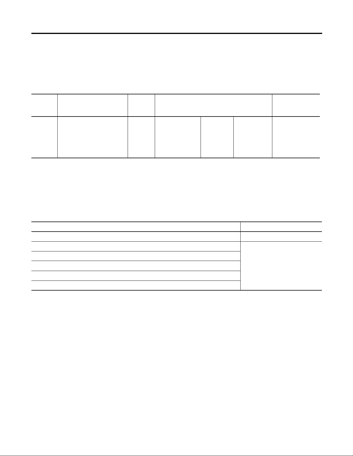
Supported Controllers
The remote I/O terminal connects to any Allen-Bradley 1771 remote
I/O link. Applicable host controllers include almost all Allen-Bradley
PLCs, computers, VME controllers, and DEC Q-Bus controllers with a
remote I/O scanner module. New PLC product releases that support
1771 remote I/O will also work with RIO InView communication
module.
When connecting an InView communication module to a controller,
refer to the user manual for your controller or scanner module for
connection diagrams and any remote I/O limitations.
Publication 2706-UM017C-EN-P - March 2006
Page 28
3-6 InView Communication Module Connections
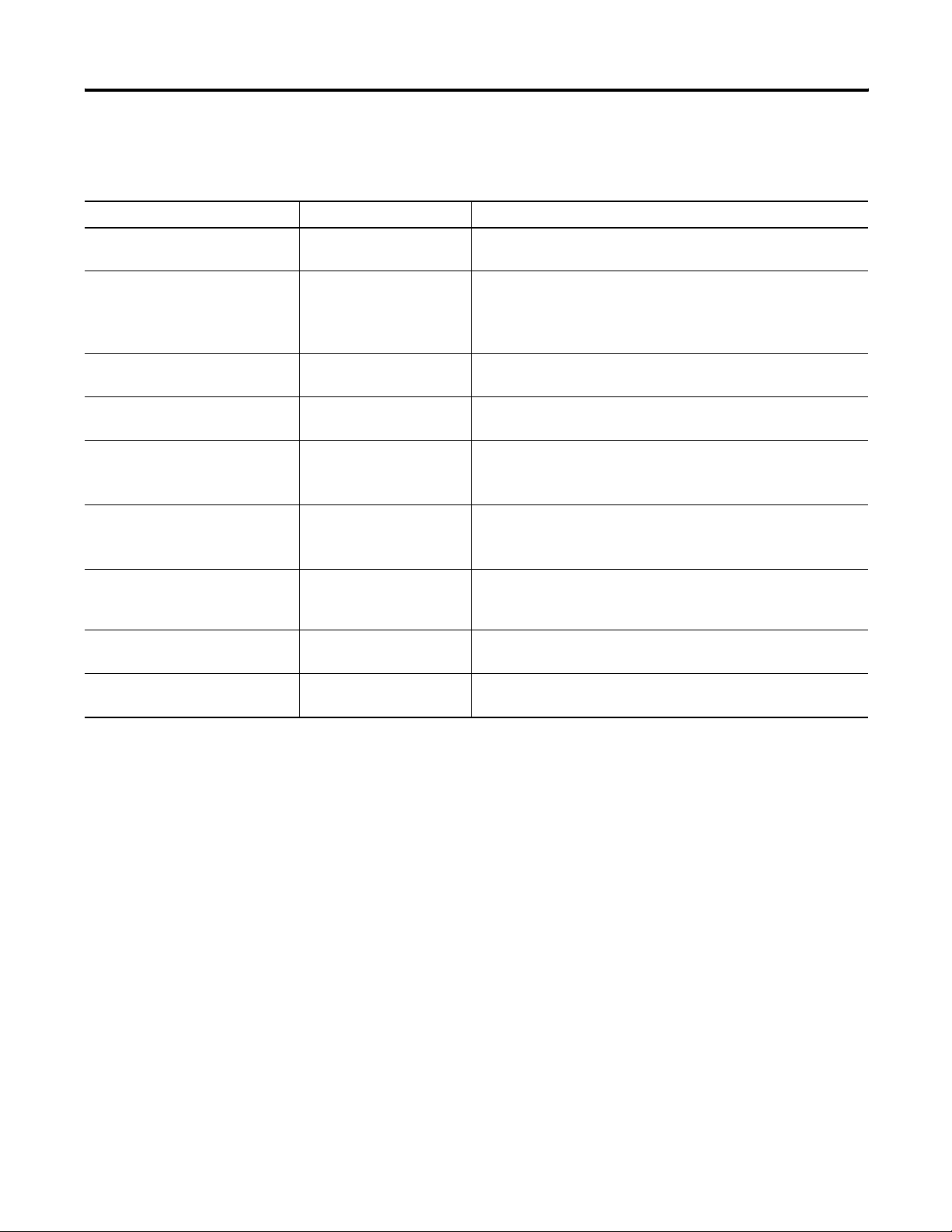
Supported RIO Connections
Controller Scanner Comments
ControlLogix 1756-DHRIO Connect InView communication modules through the 1756-DHRIO
module.
PLC-5/11, 5/15
(1)
5/20, 5/25,
5/30, 5/60, 5/80,
,
PLC Integral 1771-SN Connect InView communication modules directly to the remote I/O
port (scanner mode). Connect InView communication modules
through the 1771-SN subscanner module.
5/250
PLC-5/10, 5/12 1771-SN Connect InView communication modules through the 1771-SN
subscanner module.
PLC-2
1771-SN or 1772-SD2
(2)
Connect InView communication modules to the PLC-2 family of
processors through a 1771-SN I/O subscanner module.
PLC-3 and
PLC-3/10
SLC 5/02, 5/03, 5/04,
5/05
None
PLC-3/10
Remote I/O Scanner
(3)
Connect InView communication modules directly to a PLC-3.
Connect InView communication modules to the PLC-3/10 through the
remote I/O scanner.
1747-SN Connect InView communication modules through the 1747-SN
subscanner module. Each module provides an additional remote I/O
link for up to 4 racks.
(4)
IBM PC 6008-SI 6008-SI I/O scanner is compatible with IBM PC or compatible
computers. The scanner provides a computer access to the 1771
remote I/O link.
VME 6008-SV 6008-SV I/O scanner provides access to the 1771 remote I/O link for
VME controllers.
DEC Q-BUS 6008-SQ 6008-SQ I/O scanner provides access to the 1771 remote I/O link for
DEC Q-BUS controllers.
(1)
If using a PLC-5/15 with partial rack addressing and block transfers, you must use Series B, Rev. J or later.
(2)
If using a 1772-SD2 Remote Scanner/Distribution Panel, use revision 3 or later.
(3)
If using a 1775-S4A Remote Scanner/Distribution Panel, use Series B or later.
(4)
Only Series B and later versions of the 1747-SN subscanner support block transfers.
Publication 2706-UM017C-EN-P - March 2006
Page 29
InView Communication Module Connections 3-7
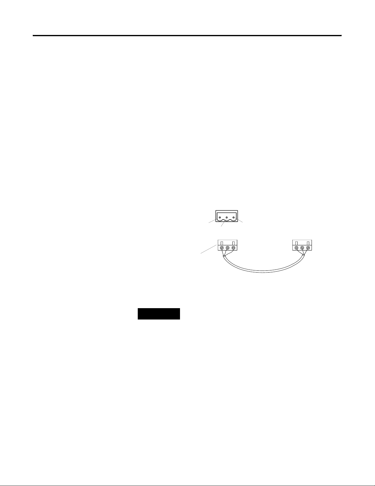
Make Remote I/O Connections
To connect an InView communication module to a remote I/O
scanner, use cable Catalog No. 1770-CD (equivalent to Belden 9463).
The maximum cable length (link distance) is determined by the
communication rate.
• 2,800 m (10,000 ft) for 57.6 Kbps
• 1,400 m (5,000 ft) for 115.2 Kbps
• 700 m (2,500 ft) for 230.4 Kbps
See Programmable Controller Wiring and Grounding Guidelines,
publication 1770-4.1. The user manual for the I/O scanner module
also provides cabling information.
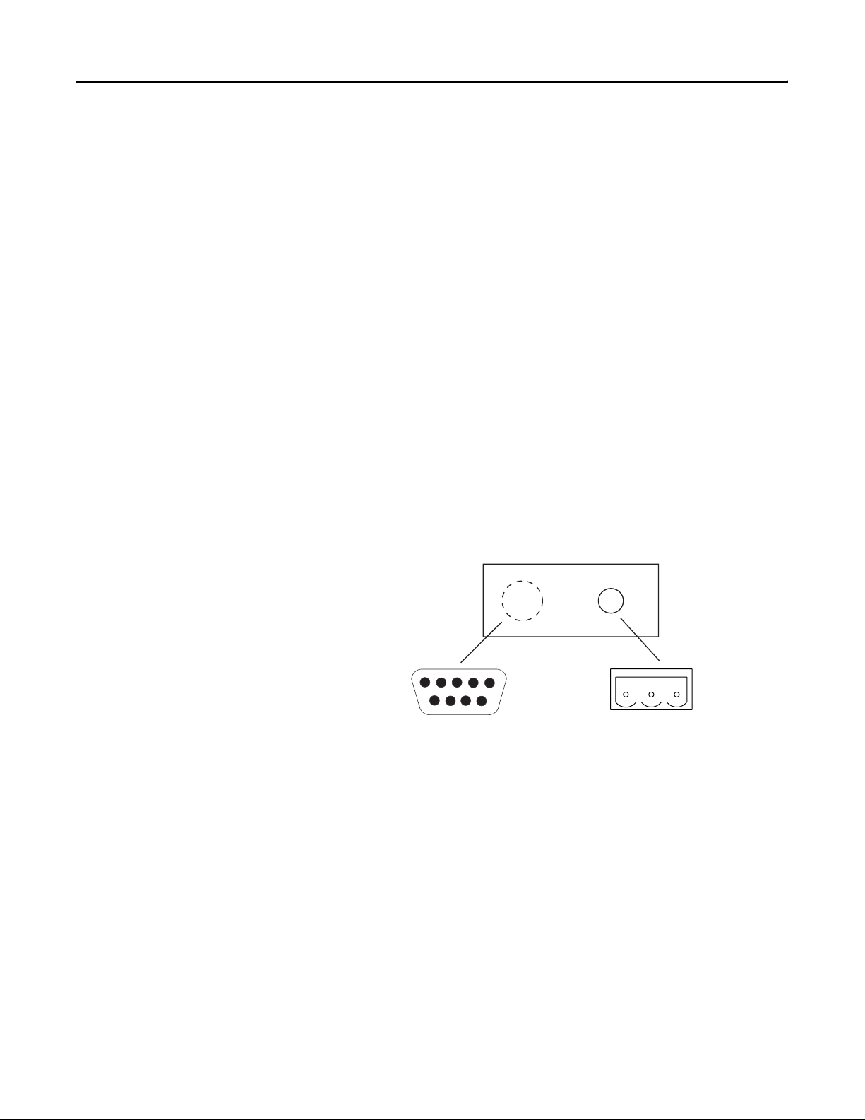
Remote I/O Connections
Remote I/O Port 3-pin Terminal Block
Connector
Clear = 2
Connector (One provided with
InView Communication
Module)
TIP
The polarity of the remote I/O connector on the
InView communication module is reversed from the
PLC scanner connector. However, the polarity is the
same as the scanner card connection to the SLC.
Shield
Blue = 1
To PLC or Scanner Remote
I/O Port
Cable (Catalog No. 1770-CD)
Publication 2706-UM017C-EN-P - March 2006
Page 30
3-8 InView Communication Module Connections
DH+ Connections
This section describes connections for the DH+ InView
communication modules including:
• DH+ ports.
• typical DH+ system configuration.
• making DH+ connections.
DH+ Ports
The DH+ versions of the InView communication modules have a DH+
port and an RS-232 port.
Use the DH+ port to:
• communicate with a PLC-5 controller on the Allen-Bradley DH+
link via the processor’s DH+ port.
• communicate with an SLC 5/04 controller (Channel 1 port) on
the Allen-Bradley DH+ link via the processor’s DH+ port.
• communicate with a ControlLogix controller on the
Allen-Bradley DH+ link via the 1756-DHRIO module.
• transfer applications over the DH+ link from a computer with a
DH+ connection.
Use the RS-232 port to:
• transfer InView communication module applications between a
computer and the DH+ InView communication module using a
direct connection;
• connect an InView display to trigger messages.
InView Communication Module DH+ Ports
InView DH+ Communication Module
12345
67 8 9
RS-232 Port
DH+ Port
Publication 2706-UM017C-EN-P - March 2006
Page 31

SLC 5/04 Processor
InView Communication Module Connections 3-9
Typical DH+ System Configuration
For more information on the Allen-Bradley DH+ link, refer to:
• Enhanced PLC-5 Programmable Controllers Installation
Instructions, publication 1785-5.7.
• Data Highway/Data Highway Plus/Data Highway II/Data
Highway 485 Cable Installation Manual, publication 1770-6.2.2.
DH+ System Configuration
InView Messaging
PLC-5 Controller
DH+ RSLinx Port DH+
communication card
installed in computer
DH+ Port
DH+ Comm
Module
RS-232 Port
77156-094
InView display
2706-P22R
2706-P4x
2706-P7x
2706-P9x
Download applications to InView
DH+ Communication Module
1) over local DH+ link
2) over a direct serial link
Publication 2706-UM017C-EN-P - March 2006
Page 32

3-10 InView Communication Module Connections
Make DH+ Connections
Use the Belden 9463 twin axial cable (1770-CD) to connect a DH+
InView communication module to the DH+ link.
You can connect a DH+ link in 2 ways.
• Trunk line/drop line - from the drop line to the connector screw
terminals on the DH+ connectors of the processor.
• Daisy chain - to the connector screw terminals on the DH+
connectors on the processor.
Follow these guidelines when installing DH+ communication links.
• Do not exceed these cable lengths:
– Trunk line-cable length: 3,048 m (10,000 cable ft)
– Drop-cable length: 30.4 m (100 cable ft)
• Do not connect more than 64 stations on a single DH+ link
PLC 5/11, -5/20, 5/26 Processor
Clear 1
Shield SH
Blue 2
DH+ Connections
PLC-5/30, -5/40, -5/46, -5/40L, - 5/60, -5/60C
-5/60L, -5/80, 5/80C, -5/86 Processor
1770-CD (Belden
Cable)
Blue 2
Shield SH
Clear 1
InView DH+ Connector
82 or 150 Ohm Resistor
Publication 2706-UM017C-EN-P - March 2006
Page 33

InView Communication Module Connections 3-11
DH-485 Terminal Connections
This section describes connections for the DH-485 InView
communication modules.
• DH-485 communication module ports
• Connecting to a single SLC controller (Point-to-Point)
• Connecting to a DH-485 network
• Connecting a computer
DH-485 Ports (RJ45)
DH-485 InView communication modules have two DH-485 ports and
an RS-232 port.
Use the DH-485 communications port to communicate with single or
multiple SLC controllers over a DH-485 network.
Use the DH-485 SLC programming connector to download InView
communication module applications.
Use the RS-232 port to connect an InView display to trigger messages.
InView Communication Module DH-485 Ports
InView DH-485 Communication Port
DH-485
Programming
Port
DH-485
Communication
Port
12345
67 8 9
RS-232 Port
Publication 2706-UM017C-EN-P - March 2006
Page 34

3-12 InView Communication Module Connections
Connect to a Single SLC Controller (Point-to-Point)
To connect a DH-485 InView communication module to a single SLC
controller use one of these cables.
• 0.3 m (1 ft) catalog no. 1747-C11
• 1.83 m (6 ft) catalog no. 1747-C10
• 6.1 m (20 ft) catalog no. 1747-C20
InView to SLC Controller Connections
SLC Controller
SLC 500 Communications Connector
InView DH-485 Communications Port
Pin 1
Pin 8
To InView Communication
Module Terminal 8-pin
Female Plug
Cable, Catalog No. 1747-C10
Cable, Catalog No. 1747-C11
Cable, Catalog No. 1747-C20
Connection Diagram
Pin #
1
2
3
4
5
6
7
8
Connect to:
Pin #
1
2
3
4
5
6
7
8
Side shown is opposite latch
To SLC Communications Connec tor
8-pin, Male, Modular Plug
Pin 1
Pin 8
The DH-485 connectors are not electrically isolated. If electrical
isolation is required, use link couplers (Catalog No. 1747-AIC).
ATTENTION
Electrical isolation using link couplers (Catalog No.
1747-AIC) is required where the distance between
the InView communication module and the SLC is
greater than 6.1 m (20 ft).
Publication 2706-UM017C-EN-P - March 2006
Page 35

InView Communication Module Connections 3-13
Connect to a DH-485 Network
This section shows how to connect an InView DH-485 communication
module to multiple SLC controllers on a DH-485 network through the
AIC link coupler.
DH-485 Connections
Link Coupler Catalog No.
Power Source
or 1747-NP1
Belden 9842
1747-AIC
Cable Catalog No.
1747-C10 Catalog No.
1747-C11 Catalog No.
1747-C20
DH-485 Comm
Module
SLC Processor
RS-232 Port
77156-094
SLC 5/01 Controller
InView Display
2706-P22R
2706-P4x
2706-P7x
2706-P9x
IMPORTANT
The DH-485 network cable requires proper
shielding, grounding and termination. Refer to Data
Highway / Data Highway Plus / Data Highway-485
Cable Installation Manual, publication 1770-6.2.2.
Publication 2706-UM017C-EN-P - March 2006
Page 36

3-14 InView Communication Module Connections
The illustration below shows how to connect an InView DH-485
communication module to a MicroLogix or SLC controller using the
AIC+ link coupler (Catalog No. 1761-NET-AIC).
InView Display Connected to MicroLogix or SLC with an AIC+
2706-P22R, 2706-P4x,
2706-P7x,2706-P9x
InView display
RS-232 Port 77156-094
DH-485 Comm
Module
InView display
RS-232 Port 77156-094
DH-485 Comm
Module
Cable Cat. No.
1761-CBL-AS03 Cat. No.
1761-CBL-AS09
2706-P22R
2706-P4x
2706-P7x
2706-P9x
Cable
Cat. No. 1761-CBL-AS03
Cat. No. 1761-CBL-AS09
AIC+
1761-NET-AIC
AIC+
1761-NET-AIC
MicroLogix 1000, 1200, 1500LSP
Cat. No.
1761-CBL-HM02
1761-CBL-AM00
SLC 5/03, 5/04, 5/05
Channel 0 Port
Cat. No. 1747-CP3
To 24V dc Power
To InView Comm Module
Do not connect the InView
Communication Module to Port
3 of the AIC+ when Port 3 is
networked to other devices.
AIC
1747-AIC
1761-NET-AIC
Belden 9842
Cable Cat. No.
1747-C10 Cat. No.
1747-C11 Cat. No.
1747-C20
AIC+
MicroLogix 1000, 1200, 1500LSP
Cat. No.
1761-CBL-HM02
1761-CBL-AM00
InView display
RS-232 Port
77156-094
DH-485 Comm
Module
2706-P22R
2706-P4x
2706-P7x
2706-P9x
Publication 2706-UM017C-EN-P - March 2006
Page 37

InView Communication Module Connections 3-15
Connect a Computer
On InView DH-485 communication modules, applications are
transferred:
• through the DH-485 programming connector to the InView
communication module.
• through any node on a DH-485 network.
To connect a computer to the InView communication module, you
need:
• a cable (same cables used to transfer applications from APS
software to SLC)
– 0.3 m (1 ft) cable, catalog no. 1747-C11
– 1.83 m (6 ft) cable, catalog no. 1747-C10
– 6.1 m (20 ft) cable, catalog no. 1747-C20
• Personal Computer Interface Converter (PIC), catalog no.
1747-PIC. The PIC connects to the computer. The cable connects
the PIC to the DH-485 programming connector.
Personal Computer Interface Converter (PIC)
The PIC receives power from a controller through DH-485
connections. When connecting a computer directly to a InView
communication module without a controller connected, you need to
use a power supply (Catalog No. 1747-NP1). The power supply
connects to the DH-485 communications connector with the same
cables used to connect an SLC processor.
IMPORTANT
The InView DH-485 communication module must be
connected to an SLC processor, DH-485 network, or
power supply (Catalog No. 1747-NP1). This
connection provides power to the PIC.
Publication 2706-UM017C-EN-P - March 2006
Page 38

3-16 InView Communication Module Connections
Connecting a Computer to DH-485 Connector Using a Power Supply
InView Messaging
Wallmount Power Supply
Cat. No. 1747-NP1
DH-485 Comm
Module
To DH-485 Programming
Connector
To DH-485
Communications Port
5-pin to 9-pin
Adapter (if
required)
Personal Computer
Interface Converter
(Cat. No. 1747-PIC)
Cable Cat. No.
1747-C10 Cat. No.
1747-C11 Cat. No.
1747-C20
Connecting a Computer to DH-485 Connector Using a DH-485 Powered Device
InView Messaging
DH-485 Comm
Module
1747-C10,
1747-C11,
1747-C20
To DH-485
Communications Port
25-pin to 9-pin
Adapter (if
required)
Personal Computer
Interface Converter
(Cat. No. 1747-PIC)
To DH-485 Programming
Connector
Cable Cat. No.
SLC 500 or DH-485
Network
Publication 2706-UM017C-EN-P - March 2006
TIP
The computer can connect to any node on the
network. It is not necessary to directly connect the
computer to the InView communication module.
Page 39

InView Communication Module Connections 3-17
ControlNet Connections
This section describes connections for the ControlNet InView
communication modules including:
• ControlNet Protocol.
• compatible ControlNet Controllers.
• ControlNet ports on the InView communication module.
• typical ControlNet network.
• making ControlNet connections.
Related Information
For more information on ControlNet products, refer to the following
publications.
• ControlNet System Overview, publication 1786-2.9
• ControlNet System Planning and Installation Manual, publication
1786-6.2.1
• ControlNet Cable System Component List, publication AG-2.2
The Allen-Bradley website (www.rockwellautomation.com) provides
information and product descriptions of ControlNet products. Under
the Products and Services heading, select Communications.
ControlNet Protocol
The InView communication module supports release 1.5 or higher of
ControlNet, including Unscheduled PLC-5C processor and
ControlLogix messaging, and redundant cabling.
ControlNet allows a flexible control architecture that can work with
multiple processors and up to 99 nodes (via taps) anywhere along the
trunk cable of the network. There is no minimum tap separation and
you can access the ControlNet network from every node (including
adapters).
Publication 2706-UM017C-EN-P - March 2006
Page 40

3-18 InView Communication Module Connections
Compatible ControlNet Controllers
The ControlNet InView communication module communicates with a
PLC-5C (using PCCC commands) or a ControlLogix processor (using
CIP protocol) using unscheduled messaging. The following controllers
are supported.
• ControlLogix using 1756-CNB module
• PLC-5/20C, -5/40C, -5/60C, -5/80C processors
ControlNet Ports
ControlNet versions of the InView communication module have a
ControlNet communication port and an RS-232 serial port.
• Use the ControlNet port to connect to devices on a ControlNet
network and transfer applications over a ControlNet network
• Use the RS-232 port to transfer applications between a computer
and the InView communication module using a direct
connection
• Use the RS-232 port to connect an InView display to trigger
messages
For details on connecting to the RS-232 port, see Connect a Computer
in this chapter.
InView Communication Module ControlNet Ports
InView ControlNet Communication Module
12345
67 8 9
RS-232 Port
NAP
ControlNet Port
Publication 2706-UM017C-EN-P - March 2006
Page 41

InView Communication Module Connections 3-19
Typical ControlNet Network
Below is a typical ControlNet network with a InView communication
module installed on a network drop.
InView Display on ControlNet Network
InView ControlNet Communication Module
RS-232 Port
Personal
Computer
Serial Link
1770-KFC
PC Interface
ControlNet Port BNC
Coaxial Cable
PLC-5/40C Controller
Flex I/O Scanner
(1784-ACN)
CNet Comm
Module
RS-232 Port
1786-RG6 Cable
OR
Serial Link
InView display
InView display
77156-094
Computer for developing
InView applications
ControlLogx 5550
1756-CNB Module
Repeater
(1786-RPT)
2706-P22R
2706-P4x
2706-P7x
2706-P9x
1784-KTC(X) Card to
ControlNet (RSLinx) & WinPFT
Personal
Computer
1784-KTC(X)
Interface Card
PLC-5/80C
= Taps
= Terminators
Publication 2706-UM017C-EN-P - March 2006
Page 42

3-20 InView Communication Module Connections
Make ControlNet Connections
Use the pinout information below to connect the InView
communication module to a ControlNet network.
IMPORTANT
Follow the ControlNet network layout and design as
specified in the ControlNet Cable System Planning
and Installation Manual, publication 1786-6.2.
ControlNet Connections
Redundant BNC Cable Connectors
NAP Connector Details
Pin # NAP Signal
1 Signal Common
2 No Connection
3 TX_H
4 TX_L
5 RX_L
NAP Connector
Channel B Channel A
Pin 1
Publication 2706-UM017C-EN-P - March 2006
6 RX_H
7 No Connection
8 Signal Common
Shell Earth Ground
Page 43

InView Communication Module Connections 3-21
NAP and Redundant Cables
Refer to the ControlNet Cable System Planning and Installation
manual, publication 1786-6.2.1, for descriptions of cables, taps, and
connectors. For information on purchasing these items, refer to the
Allen-Bradley ControlNet Cable System Component List, Publication
AG-2.2.
ControlNet Cables, Taps, and Connectors
Item Cat. No.
RG-6 quad-shield 1786-RG6
Coax repeater 1786-RPT, 1786-RPTD
Coax taps 1786-TPR, 1786-TPS, 1786-TPYR, 1786-TPYS
Network access cable 1786-CP
Coax tool kit 1786-CTK
Segment terminators 1786-XT
DeviceNet Connections
BNC connectors 1786-BNC, 1786-BNCJ, 1786-BNCP, 1786-BNCJ1
IMPORTANT
Do not connect to a network using both the
redundant cable BNC connector and the Network
Access Port (NAP).
This section describes connections for the DeviceNet InView
communication modules including:
• DeviceNet connectors.
• connections.
• typical DeviceNet network.
DeviceNet Ports
The DeviceNet versions of the InView communication modules have a
DeviceNet port and an RS-232 serial port.
• Use the DeviceNet port to connect to devices on a DeviceNet
network or transfer applications over a DeviceNet network.
• Use the RS-232 port to transfer applications between a computer
and the InView communication module using a direct
connection.
Publication 2706-UM017C-EN-P - March 2006
Page 44

3-22 InView Communication Module Connections
5
• Use the RS-232 port to connect an InView display to trigger
messages.
For details on connecting to the RS-232 port, see the last section in
this chapter.
InView Communication Module DeviceNet Ports
InView DeviceNet Communication Module
12345
67 8 9
RS-232 Port DeviceNet Port
Make DeviceNet Connections
Use one of the cables below to connect the DeviceNet version of the
InView communication module to a DeviceNet network.
DeviceNet Cables
Cable Cat. No.
DeviceNet Cable, 50 m (164 ft) 1485C-P1A50
DeviceNet Cable, 100 m (328 ft) 1485C-P1A150
DeviceNet Cable, 150 m (492 ft) 1485C-P1A300
IMPORTANT
Refer to DeviceNet Cable System Planning and
Installation manual, publication 1485-6.7.1, for
network layout and design information
Terminal Block Wiring
DeviceNet
Term i nal Block
1
Terminal Signal Function Color
1 COM Common Black
2 CAN_L Signal Low Blue
3 SHIELD Shield Uninsulated
4 CAN_H Signal High White
5 VDC+ Power Supply Red
Publication 2706-UM017C-EN-P - March 2006
Page 45

InView Communication Module Connections 3-23
Typical DeviceNet Network
Below is a typical DeviceNet network with InView communication
modules installed on 2 of the network drops.
A DeviceNet network requires a 24V dc power supply. DeviceNet
power consumption is 24 mA to 90 mA at 24V dc. The InView
communication module does not receive its power from the network.
DeviceNet Network
SLC 5/04 Controller
or
PLC-5 Controller
DeviceNet Scanner
Module (Cat. No.
1747-SDN)
DNet Comm
Module
DeviceNet Port
RS-232 Port
77156-094
InView Display
2706-P22R
2706-P4x
2706-P7x
2706-P9x
Or
Serial Link
SM
SM
C
C
Smart Motor Controller
DeviceNet Scanner
Module (Cat. No.
RS-232 Port
Computer for developing
InView applications
1771-SDN)
Download
1770-KFD
Module
RediSTATION Module
Drive
Publication 2706-UM017C-EN-P - March 2006
Page 46

3-24 InView Communication Module Connections
EtherNet/IP Connections
The EtherNet/IP InView communication module can communicate on
an EtherNet TCP/IP network with the following devices.
• PLC-5E or PLC-5 controllers with 1761-NET-ENI or 1785-ENET
module
• SLC-5/05 or SLC controllers with 1761-NET-ENI module
• ControlLogix controller with 1756-ENET/B or 1761-NET-ENI
module
• MicroLogix, CompactLogix, or FlexLogix with 1761-NET-ENI
module
• Another EtherNet/IP InView communication module
• Any device that can process CIP messages
EtherNet/IP Ports
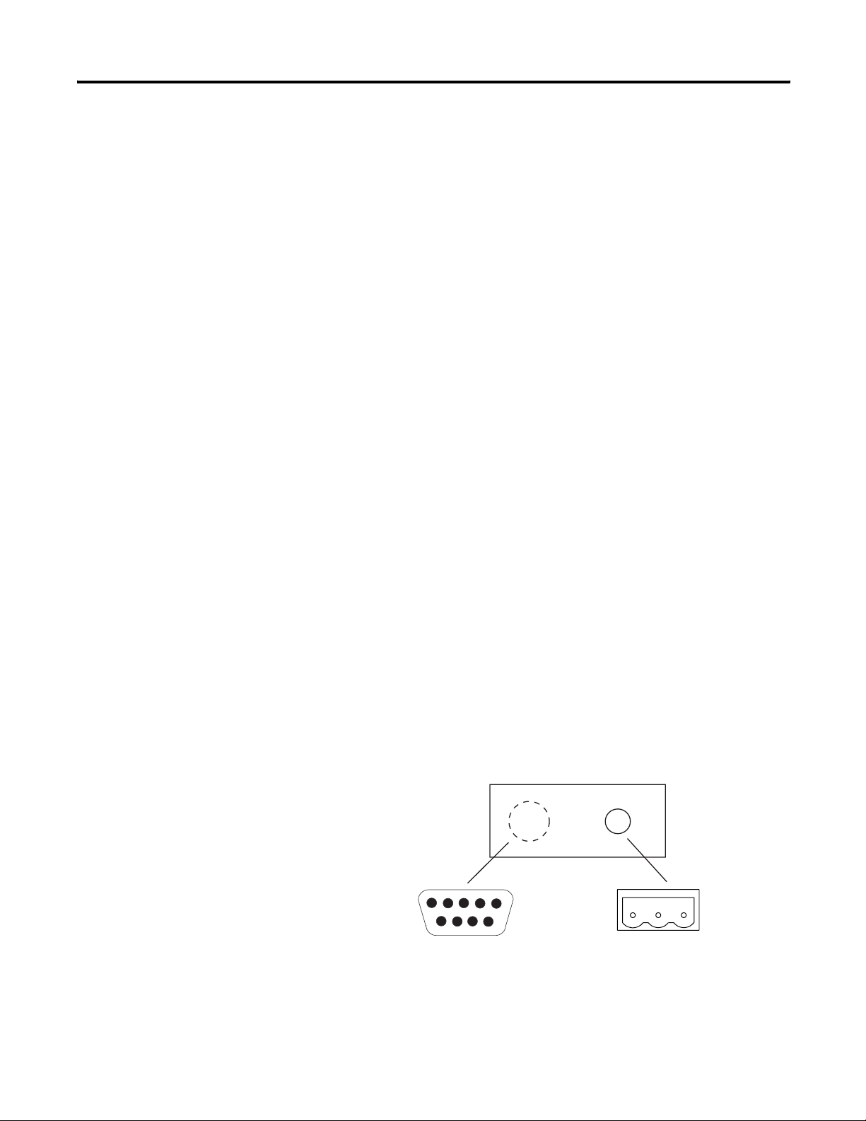
The EtherNet/IP versions of the InView communication modules have
an Ethernet RJ45 communications port and an RS-232 serial port.
• Use the RJ45 port to communicate with a logic controller on an
EtherNet/IP network and transfer applications over an
EtherNet/IP network.
• Use the RS-232 serial port to transfer applications between a
computer and the InView communication module using a direct
connection.
For connection details, see Connect a Computer on page 3-26.
• Use the RS-232 port to connect an InView display to trigger
messages.
InView Communication Module EtherNet/IP Ports
InView Ethernet Communication Module
RS-232 Port
Ethernet Connector
Publication 2706-UM017C-EN-P - March 2006
Page 47

InView Communication Module Connections 3-25
Ethernet Connector
The Ethernet connector is an RJ45, 10/100Base-T connector. The
pinout for the connector is shown below.
Ethernet Connector Details
Pin Pin Pin Name
RJ45
Connector
8
1
1TD+
2TD-
3RD+
4NC
5NC
6RD-
7NC
8NC
Direct point-to-point 10/100Base-T cables, with cross over pin-out
(1 to 3, 2 to 6, 3 to 1, 6 to 2), connect the InView communication
module Ethernet port directly to another SLC 5/05 Ethernet port (or a
computer 10/100Base-T port).
Cables
Category 5 shielded and unshielded twisted-pair cables with RJ45
connectors are supported. The maximum cable length between the
InView communication module Ethernet port and a 10/100Base-T port
on an Ethernet hub (without repeaters or fiber) is 100 m (328 ft).
However, in an industrial application, the cable length should be kept
to a minimum.
WARNING
EXPLOSION HAZARD
If you connect or disconnect the Ethernet cable with
power applied to the InView communication module
or any device on the network, an electrical arc can
occur. This could cause an explosion in hazardous
location installations. Be sure that power is removed
or the area is nonhazardous before proceeding.
Publication 2706-UM017C-EN-P - March 2006
Page 48

3-26 InView Communication Module Connections
MicroLogix, FlexLogix, or CompactLogix
with 1761-NET-ENI Module
10.0.0.5
Typical EtherNet/IP Configuration
The following illustration shows a ControlLogix controller (with
1756-ENET/B modules), a PLC-5E controller, SLC 5/05, a
MicroLogix/CompactLogix/FlexLogix (with 1761-NET-ENI module),
and an Ethernet InView communication module connected to an
EtherNet/IP network. Note that each node has a unique IP address.
EtherNet/IP Network
ControlLogix 5550 Controller
PLC-5E Controller
SLC 5/05
Connect a Computer
1756-ENET/B
10.0.0.1
10.0.0.2
EtherNet Port
Hub
ENet Comm
Module
RS-232 Port
77156-094
10.0.0.3
Ethernet Cable
InView Display
2706-P22R
2706-P4x
2706-P7x
2706-P9x
10.0.0.4
The InView communication modules have an RS-232 serial port to:
• download applications over a serial link.
• connect an InView display to trigger messages.
Communication parameters for the RS-232 port are set on the Printer
Setup screen of the Configuration Mode menu.
Publication 2706-UM017C-EN-P - March 2006
Page 49

Computer Connection
To RS-232 Port of
InView Communications Module
InView Communication Module Connections 3-27
Available Cables Cat. No.
2711-NC13, 5 m (16.4 ft) Cat. No.
2711-NC14, 10 m (32.7 ft) Cat. No.
2706-NC13, 3 m (10 ft)
Computer
InView Communication Module
RS-232 Port
9-pin male
1
1
NC
NC
2
3
4
4
NC
NC
5
5
6
6
NC
7
7
RTS
8
8
CTS
9
9
NC
NC
TXD
RXD
COM
InView Communication Module
1
2
3
4
5
6
7
8
9
77156-094
2711-NC13
2711-NC14
2706-NC13
1
2
3
4
5
6
7
8
9
2706-P4x
2706-P7x
2706-P9x
2706-P22R
Printer/Computer Port (DTE)
with Handshaking
9-pin female
1
DCD
2
RXD (Data Receive)
TXD (Data Transmit)
3
4
DTR
5
COM
6
DSR
7
RTS
8
CTS
9
NC
Publication 2706-UM017C-EN-P - March 2006
Page 50

3-28 InView Communication Module Connections
Publication 2706-UM017C-EN-P - March 2006
Page 51

Chapter
4
Application Guide
New techniques and application notes using InView displays are
continually being added and updated. Please refer to these web pages
for new or updated information.
• http://www.ab.com/eoi/inview/
• http://support.rockwellautomation.com/
ControlNet Communication and Tag Setup Screens
The InView message display communicates with PLC processors,
FlexLogix controllers, or ControlLogix 5000 controllers on a
ControlNet network using Unscheduled Messaging.
PLC Processor
ControlNet Communications Setup
1 Publication 2706-UM017C-EN-P - March 2006
Page 52

4-2 Application Guide
InView Parameters
• Node address. Node address (1 to 99 decimal) of the InView
display on the ControlNet network.
• Interscan Delay. Time interval (in ms) between display updates.
The range is 100 to 1,000 ms. The default is 100. This parameter
determines how frequently the InView display requests
unscheduled data.
Network Node Parameters
• Node Type. The type of controller that the InView display
communicates with.
• Node Address. The node address of the controller on the
ControlNet network.
For a PLC, a valid node address is 1 to 99.
IMPORTANT
ControlNet Tag Setup
All four tags for Message Trigger Address, Message
Data Address, Variable Trigger Address, Variable
Data Address, and the array sizes must be entered
and established in the controller as valid tags even if
they are not used.
Publication 2706-UM017C-EN-P - March 2006
Page 53

Application Guide 4-3
• Message Trigger Address. The controller address that triggers a
message to display. This toggles between 0 and 1 in the
controller.
• Message Data Address. The starting address of the message data
displayed. The message data contains the trigger command that
the InView display recognizes (^T[message number]^M).
• Message Array Size. The size of the array (16 to 128 characters
for ControlNet) containing the message data. The maximum
array size is dependent on the controller and must be an even
integer.
• Variable Trigger Address. The controller address that triggers a
message variable to display. This toggles between 0 and 1 in the
controller.
• Variable Data Address. The starting address of the variable data
displayed. The variable data contains the update variable
command that the InView display recognizes
(^V[variable data]\[variable number]^M).
• Variable Array Size. The size of the array (16 to 128 characters
for ControlNet) containing the variable data. The maximum
array size is dependent on the controller and must be an even
integer.
The address tags are either an Integer (N) or ASCII (A) data file. Both
the Message Trigger and Message Data addresses fall entirely within a
single 128 byte block, including the Message Data array size. You can
choose to use either an Integer or ASCII data file, but you cannot use
more than one data file. For example, a Message Trigger address of
N7:0 and a Message Data address of N9:0 is not valid. At the same
time, a Message Trigger address of N7:0 and a Message Data address
of N7:60, with a Message Data array size of 16, is not valid because
the array falls outside of the 64 word (128 byte) block.
IMPORTANT
Variable Trigger and Variable Data addresses work
the same as Variable Array Size.
Publication 2706-UM017C-EN-P - March 2006
Page 54

4-4 Application Guide
ControlLogix 5000 Controller
ControlNet Communications Setup
Publication 2706-UM017C-EN-P - March 2006
InView Parameters
• Node address. Node address (1 to 99 decimal) of the InView
display on the ControlNet network.
• Interscan Delay. Time interval (in ms) between display updates.
The range is 100 to 1,000 ms. The default is 100. This parameter
determines how frequently the InView display requests
Unscheduled data.
Network Node Parameters
• Node Type. The type of controller that the InView display
communicates with.
• Node Address. The node address of the controller on the
ControlNet network.
Page 55

Application Guide 4-5
For a Logix controller, a valid address consists of the ControlNet
module’s node number (1 to 99) followed by a space, a Logix
backplane number (usually 1) followed by a space, and a Logix slot
number.
Example: 99 1 99
IMPORTANT
ControlNet Tag Setup
All four tags for Message Trigger Address, Message
Data Address, Variable Trigger Address, Variable
Data Address, and the array sizes must be entered
and established in the controller as valid tags even if
they are not used.
• Message Trigger Address. The controller address that triggers a
message to display. This toggles between 0 and 1 in the
controller.
• Message Data Address. The starting address of the message data
displayed. The message data contains the trigger command that
the InView display recognizes (^T[message number]^M).
• Message Array Size. The size of the array (16 to 128 characters
for ControlNet) containing the message data. The maximum
array size is dependent on the controller and must be an even
integer.
Publication 2706-UM017C-EN-P - March 2006
Page 56

4-6 Application Guide
• Variable Trigger Address. The controller address that triggers a
message variable to display. This toggles between 0 and 1 in the
controller.
• Variable Data Address. The starting address of the variable data
displayed. The variable data contains the update variable
command that the InView display recognizes
(^V[variable data]\[variable number]^M).
• Variable Array Size. The size of the array (16 to 128 characters
for ControlNet) containing the variable data. The maximum
array size is dependent on the controller and must be an even
integer.
The address tags must be a SINT data type, however they can be
named anything provided it is in the following syntax: Name[element
number]. Both the Message Trigger and Message Data addresses fall
entirely within a single 128 byte block, including the Message Data
array size. You can choose to use any name, but you cannot use more
than one data file. For example, a Message Trigger address of
Mess_data[0] and a Message Data address of Message[1] is not valid. At
the same time, a Message Trigger address of Mess_data[0] and a
Message Data address of Mess_data[120], with a Message Data array
size of 16, is not valid because the array falls outside of the 128 byte
block.
DeviceNet Communication and Tag Setup Screens
IMPORTANT
The InView display can communicate as a slave device to a PLC-5
controller, SLC controller, ControlLogix controller, MicroLogix
controller, or CompactLogix controller with a DeviceNet module.
Variable Trigger and Variable Data addresses work
the same as Variable Array Size.
Publication 2706-UM017C-EN-P - March 2006
Page 57

SLC Controller
DeviceNet Communications Setup
Application Guide 4-7
InView Parameters
• Node Address. Unique address (0 to 63) of the InView display
on the DeviceNet network. You can select 64 to use the most
recent address stored on the communications card. If you select
64, the node address is set from the network using a DeviceNet
network configuration tool.
• Baud Rate. Communication rate of the DeviceNet network. The
options are AutoBaud, 125 Kbps, 250 Kbps, 500 Kbps, and PGM.
The default is 125 Kbps. If you select AutoBaud, the InView
display automatically detects the communication rate on startup
(provided there is sufficient network traffic). If you select PGM,
the InView display uses the most recent communication rate
stored on the communications card. PGM also allows the
communication rate to be set from the network using a
DeviceNet network configuration tool. You must reset the
display before the new communication takes effect. The
maximum cable length is restricted at higher communication
rates.
Publication 2706-UM017C-EN-P - March 2006
Page 58

4-8 Application Guide
I/O Scanner Parameters
• Output Size. The number of words (0 to 64) received by the
InView display from the scanner with each I/O message. The
default is 0, which means no output I/O data is exchanged with
the scanner. The output size must match the configuration in the
master device. A minimum of 19 words is needed because the
Message and Variable Data array sizes minimum are 16 bytes
each plus 1 word each for the trigger.
• Bus-off Interrupt. The action to take when a Bus-off Interrupt
occurs on the network. The options are Hold in Reset or Reset
and Continue Communications. Hold in Reset holds the InView
display and waits for DeviceNet communications to be reset.
Reset and Continue Communications resets DeviceNet
communications and attempts to re-establish the
communications link.
IMPORTANT
DeviceNet Tag Setup
All four tags for Message Trigger Address, Message
Data Address, Variable Trigger Address, Variable
Data Address, and the array sizes must be entered
and established in the controller as valid tags even if
they are not used.
Publication 2706-UM017C-EN-P - March 2006
• Message Trigger Address. The controller address that triggers a
message to display. This toggles between 0 and 1 in the
controller.
Page 59

Application Guide 4-9
• Message Data Address. The starting address of the message data
displayed. The message data contains the trigger command that
the InView display recognizes (^T[message number]^M).
• Message Array Size. The size of the array (16 to 128 characters
for DeviceNet) containing the message data. The maximum
array size is dependent on the controller and must be an even
integer.
• Message Data Swap Bytes. For DeviceNet, each message data
tag can be set to swap (or not swap) the order of bytes within a
16 bit word. Select the check box to enable swapping. Clear the
check box to disable swapping. You need to check the box
when using a SLC or PLC.
• Variable Trigger Address. The controller address that triggers a
message variable to display. This toggles between 0 and 1 in the
controller.
• Variable Data Address. The starting address of the variable data
displayed. The variable data contains the update variable
command that the InView display recognizes (^V[variable
data]\[variable number]^M).
• Variable Array Size. The size of the array (16 to 128 characters
for DeviceNet) containing the variable data. The maximum array
size is dependent on the controller and must be an even integer.
• Variable Data Swap Bytes. For DeviceNet, each variable data tag
can be set to swap (or not swap) the order of bytes within a 16
bit word. Select the check box to enable swapping. Clear the
check box to disable swapping. You need to check the box
when using a SLC controller or PLC processor.
The address tags must be an Output data type, in the following
syntax: O:[element number]. Both the Message Trigger and Message
Data addresses fall entirely within the scanners output size or a
maximum of 64 words, including the Message Data array size. For
example, a Message Trigger address of O:10 and a Message Data
address of O:32, with a scanner output size of 31 is not valid.
IMPORTANT
Variable Trigger and Variable Data addresses work
the same as Variable Data Swap Bytes.
Publication 2706-UM017C-EN-P - March 2006
Page 60

4-10 Application Guide
PLC Processor
DeviceNet Communication Setup
Publication 2706-UM017C-EN-P - March 2006
InView Parameters
• Node Address. Unique address (0 to 63) of the InView display
on the DeviceNet network. You can also select 64 to use the
most recent address stored on the communications card. If you
select 64, the node address can be set from the network using a
DeviceNet network configuration tool.
• Baud Rate. Communication rate of the DeviceNet network. The
options are AutoBaud, 125 Kbps, 250 Kbps, 500 Kbps, PGM. The
default is 125 Kbps. If you select AutoBaud, the InView display
automatically detects the communication rate on startup
(provided there is sufficient network traffic). If you select PGM,
the InView display uses the most recent communication rate
stored on the communications card. PGM also allows the
communication rate to be set from the network using a
DeviceNet network configuration tool. You must reset the
display before the new communication takes effect. The
maximum cable length is restricted at higher communication
rates.
Page 61

Application Guide 4-11
I/O Scanner Parameters
• Output Size. The number of words (0 to 64) received by the
InView display from the scanner with each I/O message. The
default is 0, which means no output I/O data is exchanged with
the scanner. The output size must match the configuration in the
master device. A minimum of 19 words is needed because the
Message and Variable Data array sizes minimums are 16 bytes
each plus 1 word each for the trigger.
• Bus-off Interrupt. The action to take when a Bus-off Interrupt
occurs on the network. The options are Hold in Reset or Reset
and Continue Communications. Hold in Reset holds the InView
display and waits for DeviceNet communications to be reset.
Reset and Continue Communications resets DeviceNet
communications and attempts to re-establish the
communications link.
IMPORTANT
DeviceNet Tag Setup
All four tags for Message Trigger Address, Message
Data Address, Variable Trigger Address, Variable
Data Address, and the array sizes must be entered
and established in the controller as valid tags even if
they are not used.
• Message Trigger Address. The controller address that triggers a
message to display. This toggles between 0 and 1 in the
controller.
Publication 2706-UM017C-EN-P - March 2006
Page 62

4-12 Application Guide
• Message Data Address. The starting address of the message data
displayed. The message data contains the trigger command that
the InView display recognizes (^T[message number]^M).
• Message Array Size. The size of the array (16 to 128 characters
for DeviceNet) containing the message data. The maximum
array size is dependent on the controller and must be an even
integer.
• Message Data Swap Bytes. For DeviceNet, each message data
tag can be set to swap (or not swap) the order of bytes within a
16 bit word. Select the check box to enable swapping. Clear the
check box to disable swapping. You need to check the box
when using a SLC controller or PLC processor.
• Variable Trigger Address. The controller address that triggers a
message variable to display. This toggles between 0 and 1 in the
controller.
• Variable Data Address. The starting address of the variable data
displayed. The variable data contains the update variable
command that the InView display recognizes (^V[variable
data]\[variable number]^M).
• Variable Array Size. The size of the array (16 to 128 characters
for DeviceNet) containing the variable data. The maximum array
size is dependent on the controller and must be an even integer.
• Variable Data Swap Bytes. For DeviceNet, each variable data tag
can be set to swap (or not swap) the order of bytes within a 16
bit word. Select the check box to enable swapping. Clear the
check box to disable swapping. You need to check the box
when using a SLC controller or PLC processor.
Publication 2706-UM017C-EN-P - March 2006
The address tags must be an Output data type, in the following
syntax: O:[element number]. Both the Message Trigger and Message
Data addresses must fall entirely within the scanners output size or a
maximum of 64 words, including the Message Data array size. For
example, a Message Trigger address of O:10 and a Message Data
address of O:32, with a scanner output size of 31 is not valid.
IMPORTANT
Variable Trigger and Variable Data addresses work
the same as Variable Data Swap Bytes.
Page 63

ControlLogix Controller
DeviceNet Communications Setup
Application Guide 4-13
InView Parameters
• Node Address. Unique address (0 to 63) of the InView display
on the DeviceNet network. You can also select 64 to use the
most recent address stored on the communications card. If you
select 64, the node address can be set from the network using a
DeviceNet network configuration tool.
• Baud Rate. Communication rate of the DeviceNet network. The
options are AutoBaud, 125 Kbps, 250 Kbps, 500 Kbps, PGM. The
default is 125 Kbps. If you select AutoBaud, the InView display
automatically detects the communication rate on startup
(provided there is sufficient network traffic). If you select PGM,
the InView display uses the most recent communication rate
stored on the communications card. PGM also allows the
communication rate to be set from the network using a
DeviceNet network configuration tool. The display must be reset
before the new communication takes effect. The maximum
cable length is restricted at higher communication rates.
Publication 2706-UM017C-EN-P - March 2006
Page 64

4-14 Application Guide
I/O Scanner Parameters
• Output Size. The number of words (0 to 64) received by the
InView display from the scanner with each I/O message. The
default is 0, which means no output I/O data is exchanged with
the scanner. The output size must match the configuration in the
master device. A minimum of 19 words is needed because the
Message and Variable Data array sizes minimum are 16 bytes
each plus 1 word each for the trigger.
• Bus-off Interrupt. The action to take when a Bus-off Interrupt
occurs on the network. The options are Hold in Reset or Reset
and Continue Communications. Hold in Reset holds the InView
display and waits for DeviceNet communications to be reset.
Reset and Continue Communications resets DeviceNet
communications and attempts to re-establish the
communications link.
IMPORTANT
DeviceNet Tag Setup
All four tags for Message Trigger Address, Message
Data Address, Variable Trigger Address, Variable
Data Address, and the array sizes must be entered
and established in the controller as valid tags even if
they are not used.
Publication 2706-UM017C-EN-P - March 2006
• Message Trigger Address. The controller address that triggers a
message to display. This toggles between 0 and 1 in the
controller.
Page 65

Application Guide 4-15
• Message Data Address. The starting address of the message data
displayed. The message data contains the trigger command that
the InView display recognizes (^T[message number]^M).
• Message Array Size. The size of the array (16 to 128 characters
for DeviceNet) containing the message data. The maximum
array size is dependent on the controller and must be an even
integer.
• Message Data Swap Byte. For DeviceNet, each message data tag
can be set to swap (or not swap) the order of bytes within a 16
bit word. Select the check box to enable swapping. Clear the
check box to disable swapping. You need to check the box
when using a SLC controller or PLC processor.
• Variable Trigger Address. The controller address that triggers a
message variable to display. This toggles between 0 and 1 in the
controller.
• Variable Data Address. The starting address of the variable data
displayed. The variable data contains the update variable
command that the InView display recognizes (^V[variable
data]\[variable number]^M).
• Variable Array Size. The size of the array (16 to 128 characters
for DeviceNet) containing the variable data. The maximum array
size is dependent on the controller and must be an even integer.
• Variable Data Swap Bytes. For DeviceNet, each variable data tag
can be set to swap (or not swap) the order of bytes within a 16
bit word. Select the check box to enable swapping. Clear the
check box to disable swapping. You need to check the box
when using a SLC controller or PLC processor.
The address tags must be an Output data type, in the following
syntax: O:[element number]. Both the Message Trigger and Message
Data addresses must fall entirely within the scanners output size or a
maximum of 64 words, including the Message Data array size. For
example, a Message Trigger address of O:10 and a Message Data
address of O:32, with a scanner output size of 31 is not valid.
IMPORTANT
Variable Trigger and Variable Data addresses work
the same as Variable Data Swap Bytes.
Publication 2706-UM017C-EN-P - March 2006
Page 66

4-16 Application Guide
Data Highway Plus (DH+) Communication and Tag Setup Screens
The InView message display communicates with PLC-5 controllers or
SLC 5/04 controllers, ControlLogix 5000 controllers, or SoftLogix
controllers on a DH+ network.
PLC-5 Controller
DH+ Communications Setup
Publication 2706-UM017C-EN-P - March 2006
InView Parameters
• Node address. Node address (0 to 77 octal) of the InView
display on the DH+ network.
• Baud Rate. The communication rate (57.6 Kbps, 115.2 Kbps,
230.4 Kbps) of the DH+ network.
Network Node Parameters
• Node Type. The type of controller that the InView display
communicates with.
Page 67

Application Guide 4-17
• Node Address. The node address (0 to 77 octal) of the controller
on the DH+ network.
IMPORTANT
DH+ Tag Setup
All four tags for Message Trigger Address, Message
Data Address, Variable Trigger Address, Variable
Data Address, and the array sizes must be entered
and established in the controller as valid tags even if
they are not used.
• Message Trigger Address. The controller address that triggers a
message to display. This toggles between 0 and 1 in the
controller.
• Message Data Address. The starting address of the message data
displayed. The message data contains the trigger command that
the InView display recognizes (^T[message number]^M).
• Message Array Size. The size of the array (16 to 80 characters for
DH+) containing the message data. The maximum array size is
dependent on the controller and must be an even integer.
• Variable Trigger Address. The controller address that triggers a
message variable to display. This toggles between 0 and 1 in the
controller.
• Variable Data Address. The starting address of the variable data
displayed. The variable data contains the update variable
command that the InView display recognizes (^V[variable
data]\[variable number]^M).
Publication 2706-UM017C-EN-P - March 2006
Page 68

4-18 Application Guide
• Variable Array Size: The size of the array (16 to 80 characters for
DHP) containing the variable data. The maximum array size is
dependent on the controller and must be an even integer.
The address tags are either an Integer (N) or ASCII (A) data file. Both
the Message Trigger and Message Data addresses must fall entirely
within a single 80 byte block, including the Message Data array size.
You can choose to use either an Integer or ASCII data file, you cannot
use more than one data file. For example, a Message Trigger address
of N7:0 and a Message Data address of N9:0 is not valid. At the same
time, a Message Trigger address of N7:0 and a Message Data address
of N7:35, with a Message Data array size of 16, is not valid because
the array falls outside of the 40 word (80 byte) block.
IMPORTANT
Variable Trigger and Variable Data addresses work
the same as Variable Array Size.
SLC 5/04 Controller
DH+ Communication Setup
Publication 2706-UM017C-EN-P - March 2006
Page 69

Application Guide 4-19
InView Parameters
• Node address. Node address (0 to 77 octal) of the InView
display on the DH+ network.
• Baud Rate. The communication rate (57.6 Kbps, 115.2 Kbps,
230.4 Kbps) of the DH+ network.
Network Node Parameters
• Node Type. The type of controller that the InView display
communicates with.
• Node Address. The node address (0 to 77 octal) of the controller
on the DH+ network.
IMPORTANT
DH+ Tag Setup
All four tags for Message Trigger Address, Message
Data Address, Variable Trigger Address, Variable
Data Address, and the array sizes must be entered
and established in the controller as valid tags even if
they are not used.
• Message Trigger Address. The controller address that triggers a
message to display. This toggles between 0 and 1 in the
controller.
Publication 2706-UM017C-EN-P - March 2006
Page 70

4-20 Application Guide
• Message Data Address. The starting address of the message data
displayed. The message data contains the trigger command that
the InView display recognizes (^T[message number]^M).
• Message Array Size. The size of the array (16 to 80 characters for
DHP) containing the message data. The maximum array size is
dependent on the controller and must be an even integer.
• Variable Trigger Address. The controller address that triggers a
message variable to display. This toggles between 0 and 1 in the
controller.
• Variable Data Address. The starting address of the variable data
displayed. The variable data contains the update variable
command that the InView display recognizes (^V[variable
data]\[variable number]^M).
• Variable Array Size. The size of the array (16 to 80 characters for
DHP) containing the variable data. The maximum array size is
dependent on the controller and must be an even integer.
The address tags are either an Integer (N) or ASCII (A) data file. Both
the Message Trigger and Message Data addresses must fall entirely
within a single 80 byte block, including the Message Data array size.
You can choose to use either an Integer or ASCII data file, you cannot
use more than one data file. For example, a Message Trigger address
of N7:0 and a Message Data address of N9:0 is not valid. At the same
time, a Message Trigger address of N7:0 and a Message Data address
of N7:35, with a Message Data array size of 16, is not valid because
the array falls outside of the 40 word (80 byte) block.
Publication 2706-UM017C-EN-P - March 2006
IMPORTANT
Variable Trigger and Variable Data addresses work
the same as Variable Array Size.
Page 71

ControlLogix 5000 Controller
DH+ Communication Setup
Application Guide 4-21
InView Parameters
• Node address. Node address (0 to 77 octal) of the InView
display on the DH+ network.
• Baud Rate. The communication rate (57.6 Kbps, 115.2 Kbps,
230.4 Kbps) of the DH+ network.
IMPORTANT
Not all communication rates are supported by all
1756-DHRIO modules.
Network Node Parameters
• Node Type. The type of controller that the InView display
communicates with.
• Node Address. The node address (0 to 77 octal) of the controller
on the DH+ network.
Publication 2706-UM017C-EN-P - March 2006
Page 72

4-22 Application Guide
IMPORTANT
DH+ Tag Setup
All four tags for Message Trigger Address, Message
Data Address, Variable Trigger Address, Variable
Data Address, and the array sizes must be entered
and established in the controller as valid tags even if
they are not used.
Publication 2706-UM017C-EN-P - March 2006
• Message Trigger Address. The controller address that triggers a
message to display. This toggles between 0 and 1 in the
controller.
• Message Data Address. The starting address of the message data
displayed. The message data contains the trigger command that
the InView display recognizes (^T[message number]^M).
• Message Array Size. The size of the array (16 to 80 characters for
DHP) containing the message data. The maximum array size is
dependent on the controller and must be an even integer.
• Variable Trigger Address. The controller address that triggers a
message variable to display. This toggles between 0 and 1 in the
controller.
• Variable Data Address. The starting address of the variable data
displayed. The variable data contains the update variable
command that the InView display recognizes (^V[variable
data]\[variable number]^M).
Page 73

Application Guide 4-23
• Variable Array Size. The size of the array (16 to 80 characters for
DHP) containing the variable data. The maximum array size is
dependent on the controller and must be an even integer.
The address tags are an Integer (N) data file. Both the Message Trigger
and Message Data addresses must fall entirely within a single 80 byte
block, including the Message Data array size. You can choose to use
any Integer data file, but you cannot use more than one data file. For
example, a Message Trigger address of N7:0 and a Message Data
address of N9:0 is not valid. At the same time, a Message Trigger
address of N7:0 and a Message Data address of N7:35, with a Message
Data array size of 16, is not valid because the array falls outside of the
40 word (80 byte) block.
DH485 Communication and Tag Setup Screens
IMPORTANT
The InView message display can communicate with the following
controllers on a DH485 network.
• SLC controller
• MicroLogix controller
• ControlLogix controller
• FlexLogix controller
• CompactLogix controller
Variable Trigger and Variable Data addresses work
the same as Variable Array Size.
Publication 2706-UM017C-EN-P - March 2006
Page 74

4-24 Application Guide
DH485 Communication Setup
SLC Controller
InView Parameters
• Node address. Node address (0 to 31 decimal) of the InView
display on the DH485 network.
• Maximum address. Address of the highest node on the network.
The default is 31. A low maximum address improves network
performance.
• Baud Rate. The communication rate (1.2 Kbps, 2.4 Kbps, 9.6
Kbps, 19.2 Kbps) of the DH485 network. The default is 19.2
Kbps.
Network Node Parameters
• Node Type. The type of controller that the InView display
communicates with.
• Node Address. The address (0 to 31 decimal) of the controller
on the DH485 network.
Publication 2706-UM017C-EN-P - March 2006
Page 75

Application Guide 4-25
IMPORTANT
DH485 Tag Setup
All four tags for Message Trigger Address, Message
Data Address, Variable Trigger Address, Variable
Data Address, and the array sizes must be entered
and established in the controller as valid tags even if
they are not used.
• Message Trigger Address. The controller address that triggers a
message to display. This toggles between 0 and 1 in the
controller.
• Message Data Address. The starting address of the message data
displayed. The message data contains the trigger command that
the InView display recognizes (^T[message number]^M).
• Message Array Size. The size of the array (16 to 80 characters for
DH485) containing the message data. The maximum array size is
dependent on the controller and must be an even integer.
• Variable Trigger Address. The controller address that triggers a
message variable to display. This toggles between 0 and 1 in the
controller.
• Variable Data Address. The starting address of the variable data
displayed. The variable data contains the update variable
command that the InView display recognizes (^V[variable
data]\[variable number]^M).
Publication 2706-UM017C-EN-P - March 2006
Page 76

4-26 Application Guide
• Variable Array Size. The size of the array (16 to 80 characters for
DH485) containing the variable data. The maximum array size is
dependent on the controller and must be an even integer.
The address tags are either an Integer (N) or ASCII (A) data file. Both
the Message Trigger and Message Data addresses must fall entirely
within a single 80 byte block, including the Message Data array size.
You can choose to use either an Integer or ASCII data file, but you
cannot use more than one data file. For example, a Message Trigger
address of N7:0 and a Message Data address of N9:0 is not valid. At
the same time, a Message Trigger address of N7:0 and a Message Data
address of N7:35, with a Message Data array size of 16, is not valid
because the array falls outside of the 40 word (80 byte) block.
IMPORTANT
Variable Trigger and Variable Data addresses work
the same as Variable Array Size.
ControlLogix Controller
DH485 Communication Setup
Publication 2706-UM017C-EN-P - March 2006
Page 77

Application Guide 4-27
InView Parameters
• Node address. Node address (0 to 31 decimal) of the InView
Display on the DH485 network.
• Maximum address. Address of the highest node on the network.
The default is 31. A low maximum address improves network
performance.
• Baud Rate. The communication rate (1.2 Kbps, 2.4 Kbps,
9.6 Kbps, 19.2 Kbps) of the DH485 network. The default is
19.2 Kbps.
Network Node Parameters
• Node Type. The type of controller that the InView display
communicates with.
• Node Address. The address (0 to 31 decimal) of the controller
on the DH-485 network.
IMPORTANT
DH485 Tag Setup
All four tags for Message Trigger Address, Message
Data Address, Variable Trigger Address, Variable
Data Address, and the array sizes must be entered
and established in the controller as valid tags even if
they are not used.
Publication 2706-UM017C-EN-P - March 2006
Page 78

4-28 Application Guide
• Message Trigger Address. The controller address that triggers a
message to display. This toggles between 0 and 1 in the
controller.
• Message Data Address. The starting address of the message data
displayed. The message data contains the trigger command that
the InView display recognizes (^T[message number]^M ).
• Message Array Size. The size of the array (16 to 80 characters for
DH485) containing the message data. The maximum array size is
dependent on the controller and must be an even integer.
• Variable Trigger Address. The controller address that triggers a
message variable to display. This toggles between 0 and 1 in the
controller.
• Variable Data Address. The starting address of the variable data
displayed. The variable data contains the update variable
command that the InView display recognizes (^V[variable
data]\[variable number]^M ).
• Variable Array Size. The size of the array (16 to 80 characters for
DH485) containing the variable data. The maximum array size is
dependent on the controller and must be an even integer.
EtherNet Communication and Tag Setup Screens
The address tags are an Integer ( N ) data file. Both the Message
Trigger and Message Data addresses must fall entirely within a single
80 byte block, including the Message Data array size. You can choose
to use any Integer data file, but you cannot use more than one data
file. For example, a Message Trigger address of N7:0 and a Message
Data address of N9:0 is not valid. At the same time, a Message Trigger
address of N7:0 and a Message Data address of N7:35, with a Message
Data array size of 16, is not valid because the array falls outside of the
40 word (80 byte ) block.
IMPORTANT
The InView message display can communicate with the following
controllers on an EtherNet/IP network. Be sure to set up the Ethernet
communication module serially using a 2706-NC13 cable before
hanging/mounting the unit. The Ethernet configuration must be set
before it can function on the network.
Variable Trigger and Variable Data addresses work
the same as Variable Array Size.
Publication 2706-UM017C-EN-P - March 2006
• PLC-5E controller or SLC 5/05 controller
• ControlLogix controller (with 1756-ENET/B or /ENBx module)
• MicroLogix controller, FlexLogix controller, CompactLogix
controller (with ENI module)
Page 79

SLC 5/05 Controller
EtherNet/IP Communication Setup
Application Guide 4-29
InView Parameters
• InterScan Delay. Time interval (in milliseconds) between the
InView display delays before re-reading data from the logic
controller. The range is 100 to 1,000 ms. The default is 100 ms.
Network Node Parameters
• Node Type. The type of controller that the InView display
communicates with.
• Node Address. The IP address or host name of the controller on
the EtherNet/IP network that the InView display communicates.
The IP address is formatted as four sets of decimal numbers with
periods between them (10.0.0.1). The range of values for the
first set of numbers is 1 to 255, unless all fields are 0.0.0.0. The
range of values for the last three sets of decimal numbers is 0 to
255.
Publication 2706-UM017C-EN-P - March 2006
Page 80

4-30 Application Guide
• Node Path. A 256-character string identifying the path to the end
node.
EtherNet/IP Configuration
EtherNet Configuration
• DHCP/BootP Enable. If you select this check box, the InView
display is automatically assigned an IP address, Subnet Mask,
and Gateway Address. These fields become read-only if the
check box is selected. Clear the check box to manually assign an
IP Address, Subnet Mask and Gateway Address.
• IP Address. A unique IP address of the InView display node on
the network. The default value is 0.0.0.0.
• Subnet Mask. A unique IP address of the InView display’s subnet
mask. This parameter interprets IP addresses when the network
is divided into multiple networks. The value 0.0.0.0 is not a valid
subnet mask.
Publication 2706-UM017C-EN-P - March 2006
Page 81

Application Guide 4-31
• Gateway Address. A unique IP address of the Gateway
connecting two individual IP networks into a system of
networks. When a node needs to communicate with another
network, the Gateway transfers the data between the two
networks. This parameter interprets IP addresses when the
network is divided into multiple networks. The first field cannot
be 0 if any other fields contain a 0. This address can be left
blank.
DNS Parameters
• DNS Enable. The DNS coverts more convenient host names into
IP addresses. If you select this check box, you are allowed to
assign a domain name to the domain server. Clear the check box
to disable the Domain Server and Domain Name fields.
• DNS Server. 32-bit IP address of the DNS Server.
• Domain Name. Character string mapping the local domain name
to the IP address of the DNS Server.
Timeout Parameters
• Connection Timeout. The number of milliseconds to establish a
connection with another node on the network. Values range
from 10,000 to 1,073,741,824 ms. The default is 15,000 ms.
• Reply Timeout. The number of milliseconds to wait for a reply
from another node on the network. Values range from 10,000 to
1,073,741,824 ms. The default value is 15,000 ms.
• Inactivity Timeout. The number of minutes of inactivity allowed
before a connection is closed. Values range from 10 to 140
minutes. The default is 10 minutes.
IMPORTANT
All four tags for Message Trigger Address, Message
Data Address, Variable Trigger Address, Variable
Data Address, and the array sizes must be entered
and established in the controller as valid tags even if
they are not used.
Publication 2706-UM017C-EN-P - March 2006
Page 82

4-32 Application Guide
EtherNet/IP Tag Setup
• Message Trigger Address. The controller address that triggers a
message to display. This toggles between 0 and 1 in the
controller.
• Message Data Address. The starting address of the message data
displayed. The message data contains the trigger command that
the InView display recognizes (^T[message number]^M ).
• Message Array Size. The size of the array (16 to 80 characters for
SLC 5/05 controller) containing the message data. The maximum
array size is dependent on the controller and must be an even
integer.
• Variable Trigger Address. The controller address that triggers a
message variable to display. This toggles between 0 and 1 in the
controller.
• Varia ble D at a Add re ss. The starting address of the variable data
displayed. The variable data contains the update variable
command that the InView display recognizes
(^V[variable data]\[variable number]^M ).
Publication 2706-UM017C-EN-P - March 2006
Page 83

Application Guide 4-33
• Variable Array Size. The size of the array (16 to 80 characters for
SLC 5/05 controller) containing the variable data. The maximum
array size is dependent on the controller and must be an even
integer.
The address tags are either an Integer ( N ) or ASCII ( A ) data file.
Both the Message Trigger and Message Data addresses must fall
entirely within a single 80 byte block, including the Message Data
array size. You can choose to use either an Integer or ASCII data file,
but you cannot use more than one data file. For example, a Message
Trigger address of N7:0 and a Message Data address of N9:0 is not
valid. At the same time, a Message Trigger address of N7:0 and a
Message Data address of N7:35, with a Message Data array size of 16,
is not valid because the array falls outside of the 40 word (80 byte )
block.
IMPORTANT
Variable Trigger and Variable Data addresses work
the same as Variable Array Size.
PLC-5E Controller
EtherNet/IP Communication Setup
Publication 2706-UM017C-EN-P - March 2006
Page 84

4-34 Application Guide
InView Parameters
• InterScan Delay. Time interval (in milliseconds) between the
InView display delays before re-reading data from the logic
controller. The range is 100 to 1,000 ms. The default is 100 ms.
Network Node Parameters
• Node Type. The type of controller that the InView display
communicates with.
• Node Address. The IP address or host name of the controller on
the EtherNet/IP network that the InView display communicates.
The IP address is formatted as four sets of decimal numbers with
periods between them (10.0.0.1). The range of values for the
first set of numbers is 1 to 255, unless all fields are 0.0.0.0. The
range of values for the last three sets of decimal numbers is 0 to
255.
• Node Path: A 256-character string identifying the path to the end
node.
EtherNet/IP Configuration
Publication 2706-UM017C-EN-P - March 2006
Page 85

Application Guide 4-35
EtherNet Configuration
• DHCP/BootP Enable. If you select this check box, the InView
Display is automatically assigned an IP address, Subnet Mask,
and Gateway Address. These fields become read-only if the
check box is selected. Clear the check box to manually assign an
IP Address, Subnet Mask and Gateway Address.
• IP Address. A unique IP address of the InView display node on
the network. The default value is 0.0.0.0.
• Subnet Mask. A unique IP address of the InView display’s subnet
mask. This parameter interprets IP addresses when the network
is divided into multiple networks. The value 0.0.0.0 is not a valid
subnet mask.
• Gateway Address. A unique IP address of the Gateway
connecting two individual IP networks into a system of
networks. When a node needs to communicate with another
network, the Gateway transfers the data between the two
networks. This parameter interprets IP addresses when the
network is divided into multiple networks. The first field cannot
be 0 if any other fields contain a 0. This address can be left
blank.
DNS Parameters
• DNS Enable. The DNS coverts more convenient host names into
IP addresses. If you select this check box, you are allowed to
assign a domain name to the domain server. Clear the check box
to disable the Domain Server and Domain Name fields.
• DNS Server. 32-bit IP address of the DNS Server.
• Domain Name. Character string mapping the local domain name
to the IP address of the DNS Server.
Timeout Parameters
• Connection Timeout. The number of milliseconds to establish a
connection with another node on the network. Values range
from 10,000 to 1,073,741,824 ms. The default is 15,000 ms.
• Reply Timeout. The number of milliseconds to wait for a reply
from another node on the network. Values range from 10,000 to
1,073,741,824 ms. The default value is 15,000 ms.
• Inactivity Timeout. The number of minutes of inactivity allowed
before a connection is closed. Values range from 10 to 140
minutes. The default is 10 minutes.
Publication 2706-UM017C-EN-P - March 2006
Page 86

4-36 Application Guide
IMPORTANT
EtherNet/IP Tag Setup
All four tags for Message Trigger Address, Message
Data Address, Variable Trigger Address, Variable
Data Address, and the array sizes must be entered
and established in the controller as valid tags even if
they are not used.
Publication 2706-UM017C-EN-P - March 2006
• Message Trigger Address. The controller address that triggers a
message to display. This toggles between 0 and 1 in the
controller.
• Message Data Address. The starting address of the message data
displayed. The message data contains the trigger command that
the InView display recognizes (^T[message number]^M ).
• Message Array Size. The size of the array (16 to 230 characters
for PLC-5E controller) containing the message data. The
maximum array size is dependent on the controller and must be
an even integer.
• Variable Trigger Address. The controller address that triggers a
message variable to display. This toggles between 0 and 1 in the
controller.
• Variable Data Address. The starting address of the variable data
displayed. The variable data needs to contain the update
variable command that the InView display recognizes
(^V[variable data]\[variable number]^M ).
Page 87

Application Guide 4-37
• Variable Array Size. The size of the array (16 to 230 characters
for PLC-5E controller) containing the variable data. The
maximum array size is dependent on the controller and must be
an even integer.
The address tags are either an Integer ( N ) or ASCII ( A ) data file.
Both the Message Trigger and Message Data addresses must fall
entirely within a single 230 byte block, including the Message Data
array size. You can choose to use either an Integer or Ascii data file,
but you cannot use more than one data file. For example, a Message
Trigger address of N7:0 and a Message Data address of N9:0 is not
valid. At the same time, a Message Trigger address of N7:0 and a
Message Data address of N7:110, with a Message Data array size of 16,
is not valid because the array falls outside of the 115 word (230 byte)
block.
IMPORTANT
Variable Trigger and Variable Data addresses work
the same as Variable Array Size.
ControlLogix Controller
EtherNet/IP Communication Setup
Publication 2706-UM017C-EN-P - March 2006
Page 88

4-38 Application Guide
InView Parameters
• InterScan Delay. Time interval (in milliseconds) between the
InView display delays before re-reading data from the logic
controller. The range is 100 to 1,000 ms. The default is 100 ms.
Network Node Parameters
• Node Type. The type of controller that the InView display
communicates with.
• Node Address. The IP address or host name of the controller on
the EtherNet/IP network that the InView display communicates.
The IP address is formatted as four sets of decimal numbers with
periods between them (10.0.0.1). The range of values for the
first set of numbers is 1 to 255, unless all fields are 0.0.0.0. The
range of values for the last three sets of decimal numbers is 0 to
255.
• Node Path. A 256-character string identifying the path to the end
node. At a minimum for a Logix controller, a valid node path is
needed to show where the processor is. Typically it is a Logix
backplane number (usually 1) followed by a space, and a Logix
slot number. Example: 1 0
EtherNet/IP Configuration
Publication 2706-UM017C-EN-P - March 2006
Page 89

Application Guide 4-39
EtherNet Configuration
• DHCP/BootP Enable. If you select this check box, the InView
display is automatically assigned an IP address, Subnet Mask,
and Gateway Address. These fields become read-only if the
check box is selected. Clear the check box to manually assign an
IP Address, Subnet Mask and Gateway Address.
• IP Address. A unique IP address of the InView display node on
the network. The default value is 0.0.0.0.
• Subnet Mask. A unique IP address of the InView display’s subnet
mask. This parameter interprets IP addresses when the network
is divided into multiple networks. The value 0.0.0.0 is not a valid
subnet mask.
• Gateway Address: A unique IP address of the Gateway
connecting two individual IP networks into a system of
networks. When a node needs to communicate with another
network, the Gateway transfers the data between the two
networks. This parameter interprets IP addresses when the
network is divided into multiple networks. The first field cannot
be 0 if any other fields contain a 0. This address can be left
blank.
DNS Parameters
• DNS Enable. The DNS coverts more convenient host names into
IP addresses. If you select this check box, you are allowed to
assign a domain name to the domain server. Clear the check box
to disable the Domain Server and Domain Name fields.
• DNS Server. 32-bit IP address of the DNS Server.
• Domain Name. Character string mapping the local domain name
to the IP address of the DNS Server.
Timeout Parameters
• Connection Timeout. The number of milliseconds to establish a
connection with another node on the network. Values range
from 10,000 to 1,073,741,824 ms. The default is 15,000 ms.
• Reply Timeout. The number of milliseconds to wait for a reply
from another node on the network. Values range from 10,000 to
1,073,741,824 ms. The default value is 15,000 ms.
• Inactivity Timeout. The number of minutes of inactivity allowed
before a connection is closed. Values range from 10 to 140
minutes. The default is 10 minutes.
Publication 2706-UM017C-EN-P - March 2006
Page 90

4-40 Application Guide
IMPORTANT
All four tags for Message Trigger Address, Message
Data Address, Variable Trigger Address, Variable
Data Address, and the array sizes must be entered
and established in the controller as valid tags even if
they are not used.
EtherNet I/P Tag Setup
Publication 2706-UM017C-EN-P - March 2006
• Message Trigger Address. The controller address that triggers a
message to display. This toggles between 0 and 1 in the
controller.
• Message Data Address. The starting address of the message data
displayed. The message data contains the trigger command that
the InView display recognizes (^T[message number]^M ).
• Message Array Size. The size of the array (16 to 254 characters
for a ControlLogix controller) containing the message data. The
maximum array size is dependent on the controller and must be
an even integer.
• Variable Trigger Address. The controller address that triggers a
message variable to display. This toggles between 0 and 1 in the
controller.
• Variable Data Address. The starting address of the variable data
displayed. The variable data contains the update variable
command that the InView display recognizes (^V[variable
data]\[variable number]^M).
Page 91

Application Guide 4-41
• Variable Array Size. The size of the array (16 to 254 characters
for a ControlLogix controller) containing the variable data. The
maximum array size is dependent on the controller and must be
an even integer.
The address tags are a SINT data type, however they can be named
anything provided it follows this syntax: Name[element number]. Both
the Message Trigger and Message Data addresses must fall entirely
within a single 254 byte block, including the Message Data array size.
You can choose to use any name, but you cannot use more than one
data file. For example, a Message Trigger address of Message_data[0]
and a Message Data address of Message[1] is not valid. At the same
time, a Message Trigger address of Message_data[0] and a Message
Data address of Message_data[250], with a Message Data array size of
16, is not valid because the array falls outside of the 254 byte block.
RIO Communication and Tag Setup Screens
IMPORTANT
The InView Message Display communicates with the following
controllers on a Remote I/O network.
• PLC-5 controller
• SLC 5/03, 5/04 or 5/05 controller with a 1747-SN/B scanner
• ControlLogix controller
Variable Trigger and Variable Data addresses work
the same as Variable Array Size.
Publication 2706-UM017C-EN-P - March 2006
Page 92

4-42 Application Guide
PLC-5 Controller
Remote I/O Communication Setup
PLC/Scanner Parameters
• Node Type. The type of controller that the InView display
communicates with.
InView Parameters
• Rack. The unique address (0 to 76 octal) of the InView display
on the Remote I/O link. The options are limited to the rack
addresses supported by the type of controller selected under
PLC/Scanner.
• Baud Rate. The communication rate used on the Remote I/O
link. The options are 57.6 Kbps (3,048 m (10,000 ft) max. cable
length), 115.2 Kbps (1,524 m (5,000 ft) max. cable length), 230.4
Kbps (762 m (2,500 ft) max. cable length).
• Module. The module groups used by the InView Display in the
rack. Each check box represents 2 module groups. The module
groups must be contiguous.
• Chassis. Specifies whether the terminal occupies the last module
group (no higher module groups assigned) in the rack.
• Enable Pass-through. Enables or disables Pass-through for
application transfers between a computer on the DH+ network
and a InView communication module on the Remote I/O
network.
Publication 2706-UM017C-EN-P - March 2006
Page 93

Application Guide 4-43
IMPORTANT
Remote I/O Tag Setup
All four tags for Message Trigger Address, Message
Data Address, Variable Trigger Address, Variable
Data Address, and the array sizes must be entered
and established in the controller as valid tags even if
they are not used.
• Message Trigger Address. The controller address that triggers a
message to display. This toggles between 0 and 1 in the
controller.
• Message Data Address. The starting address of the message data
displayed. The message data needs to contain the trigger
command that the InView display recognizes
(^T[message number]^M).
• Message Array Size. The size of the array (16 to 128 characters
for RIO) containing the message data. The maximum array size
is dependent on the controller and must be an even integer.
• Variable Trigger Address. The controller address that triggers a
message variable to display. This toggles between 0 and 1 in the
controller.
• Variable Data Address. The starting address of the variable data
displayed. The variable data needs to contain the update
variable command that the InView Display recognizes
(^V[variable data]\[variable number]^M).
Publication 2706-UM017C-EN-P - March 2006
Page 94

4-44 Application Guide
• Variable Array Size. The size of the array (16 to 128 characters
for RIO) containing the variable data. The maximum array size is
dependent on the controller and must be an even integer.
The address tags are either an Integer (N) or ASCII (A) data file. Both
the Message Trigger and Message Data addresses must fall entirely
within its designated block transfer, including the Message Data array
size.
IMPORTANT
Variable Trigger and Variable Data addresses work
the same as Variable Array Size.
Block Transfer Parameters
• Address. The starting address (in the correct controller format)
of the message data for the Block Transfer Read or Block
Transfer Write.
• Length. The number of words to transfer (1 to 62, or 64). The
InView display uses Length to identify the message blocks. You
must configure 2 block transfers (only 2). The first block, labeled
Message, contains both the Message Trigger and Data addresses.
The second block, labeled Variable, contains the Variable Trigger
and Variable Data addresses. Word 63 is reserved for the RIO
Pass-through.
Publication 2706-UM017C-EN-P - March 2006
Page 95

SLC Controller with 1747-SN/B Scanner
Remote I/O Communication Setup
Application Guide 4-45
PLC Processor/Scanner Parameters
• Node Type. The type of controller that the InView display
communicates with.
InView Parameters
• Rack. The unique address (0 to 76 octal) of the InView display
on the remote I/O link. The options are limited to the rack
addresses supported by the type of controller selected under
PLC/Scanner.
• Baud Rate. The communication rate used on the remote I/O
link. The options are 57.6 Kbps (3,048 m (10,000 ft) max. cable
length), 115.2 Kbps (1,524 m (5,000 ft) max. cable length), 230.4
Kbps (762 m (2,500 ft) max. cable length).
• Module. The module groups used by the InView display in the
rack. Each check box represents 2 module groups. The module
groups must be contiguous.
• Chassis. Specifies whether the terminal occupies the last module
group (no higher module groups assigned) in the rack.
Publication 2706-UM017C-EN-P - March 2006
Page 96

4-46 Application Guide
• Enable Pass-through. Enables or disables Pass-through for
application transfers between a computer on the DH+ network
and a PanelView terminal on the remote I/O network.
IMPORTANT
Remote I/O Tag Setup
All four tags for Message Trigger Address, Message
Data Address, Variable Trigger Address, Variable
Data Address, and the array sizes must be entered
and established in the controller as valid tags even if
they are not used.
Publication 2706-UM017C-EN-P - March 2006
• Message Trigger Address. The controller address that triggers a
message to display. This toggles between 0 and 1 in the
controller.
• Message Data Address. The starting address of the message data
displayed. The message data contains the trigger command that
the InView display recognizes (^T[message number]^M).
• Message Array Size. The size of the array (16 to 128 characters
for RIO) containing the message data. The maximum array size
is dependent on the controller and must be an even integer.
• Variable Trigger Address. The controller address that triggers a
message variable to display. This toggles between 0 and 1 in the
controller.
Page 97

Application Guide 4-47
• Variable Data Address. The starting address of the variable data
displayed. The variable data contains the update variable
command that the InView display recognizes
(^V[variable data]\[variable number]^M).
• Variable Array Size. The size of the array (16 to 128 characters
for RIO) containing the variable data. The maximum array size is
dependent on the controller and must be an even integer.
The address tags are either an Integer (N) or ASCII (A) data file. Both
the Message Trigger and Message Data addresses must fall entirely
within its designated block transfer, including the Message Data array
size.
IMPORTANT
Variable Trigger and Variable Data addresses work
the same as Variable Array Size.
Block Transfer Parameters
• Address. The starting address (in the correct controller format)
of the message data for the Block Transfer Read or Block
Transfer Write.
• Length. The number of words to transfer (1 to 62, or 64). The
InView display uses Length to identify the message blocks. You
must configure 2 block transfers (only 2). The first block, labeled
Message, contains both the Message Trigger and Data addresses.
The second block, labeled Variable, contains the Variable Trigger
and Variable Data addresses. Word 63 is reserved for the RIO
Pass-through.
Publication 2706-UM017C-EN-P - March 2006
Page 98

4-48 Application Guide
ControlLogix 5000 Controller
Remote I/O Communication Setup
PLC/Scanner Parameters
• Node Type. The type of controller that the InView display
communicates with.
InView Parameters
• Rack. The unique address (0 to 76 octal) of the InView display
on the remote I/O link. The options are limited to the rack
addresses supported by the type of controller selected under
PLC/Scanner.
• Baud Rate. The communication rate used on the remote I/O
link. The options are 57.6 Kbps (3,048 m (10,000 ft) max. cable
length), 115.2 Kbps (1,524 m (5,000 ft) max. cable length),
230.4 Kbps (762 m (2,500 ft) max. cable length).
• Module. The module groups used by the InView display in the
rack. Each check box represents 2 module groups. The module
groups must be contiguous.
• Chassis. Specifies whether the terminal occupies the last module
group (no higher module groups assigned) in the rack.
Publication 2706-UM017C-EN-P - March 2006
Page 99

Application Guide 4-49
• Enable Pass-through. Enables or disables Pass-through for
application transfers between a computer on the DH+ network
and a PanelView terminal on the remote I/O network.
IMPORTANT
Remote I/O Tag Setup
All four tags for Message Trigger Address, Message
Data Address, Variable Trigger Address, Variable
Data Address, and the array sizes must be entered
and established in the controller as valid tags even if
they are not used.
• Message Trigger Address. The controller address that triggers a
message to display. This toggles between 0 and 1 in the
controller.
• Message Data Address. The starting address of the message data
displayed. The message data contains the trigger command that
the InView display recognizes (^T[message number]^M).
• Message Array Size. The size of the array (16 to 128 characters
for RIO) containing the message data. The maximum array size
is dependent on the controller and must be an even integer.
• Variable Trigger Address. The controller address that triggers a
message variable to display. This toggles between 0 and 1 in the
controller.
• Variable Data Address. The starting address of the variable data
displayed. The variable data contains the update variable
command that the InView Display recognizes
(^V[variable data]\[variable number]^M).
Publication 2706-UM017C-EN-P - March 2006
Page 100

4-50 Application Guide
• Variable Array Size. The size of the array (16 to 128 characters
for RIO) containing the variable data. The maximum array size is
dependent on the controller and must be an even integer.
The address tags are an Integer (N) data file. Both the Message Trigger
and Message Data addresses must fall entirely within its designated
block transfer, including the Message Data array size.
Save or Download an Application File
IMPORTANT
Variable Trigger and Variable Data addresses work
the same as Variable Array Size.
Block Transfer Parameters
• Address. The starting address (in the correct controller format)
of the message data for the Block Transfer Read or Block
Transfer Write.
• Length. The number of words to transfer (1 to 62, or 64). The
InView display uses Length to identify the message blocks. You
must configure 2 block transfers (only 2). The first block, labeled
Message, contains both the Message Trigger and Data addresses.
The second block, labeled Variable, contains the Variable Trigger
and Variable Data addresses. Word 63 is reserved for the RIO
Pass-through.
After you select a communication protocol and configure the
communication and tag parameters, or if you opened a previously
saved .ivc configuration file, download or save the application file.
The last screen that displays lets you download or save the
configuration.
Publication 2706-UM017C-EN-P - March 2006
Configuration Download or Save
 Loading...