

Page 1
Installation Instructions
English Section
InView P22R Adapter Plate
(Catalog Number 2706-PNR2)
Overview
For additional information, refer to:
• InView User Manual, publication 2706-UM016.
• InView P22R Installation Instructions, publication 2706-IN014.
• The InView publications can be found in the Manuals-On-Line section of
www.ab.com or theautomationbookstore.com.
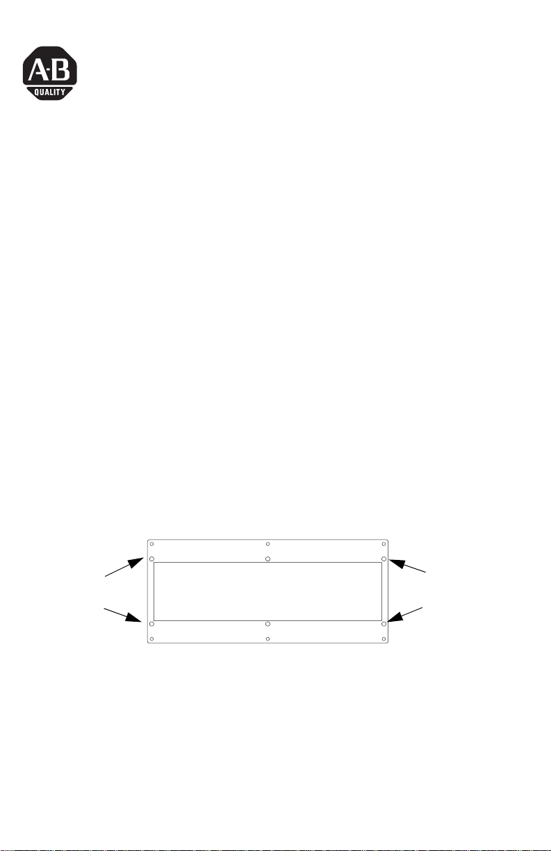
Adapter Plate Mounting
The following steps provide instructions for installing the adapter plate in an
existing DL40 Plus four-line display panel opening.
1. Drill the appropriate mounting holes in the enclosure or panel.
Drill Holes
0.25 in (6.35 mm)
2. Remove the six mounting nuts from the hardware bag provided with the
plate.
3. Position the adapter plate (2706-PNR2) in the panel or enclosure mounting
hole.
4. Install nuts and alternately tighten the nuts to a torque of 0.904 Nm (8 in-lb).
Publication 2706-IN020A-EN-P - January 2004
Drill Holes
0.25 in (6.35 mm)
Page 2
InView Display Mounting
The following instructions provide panel cutout dimensions for the InView P22R
Panel Mount Display.
The InView P22R mounts in a custom panel or enclosure. When it is properly
installed, the faceplate provides a NEMA Type 12, 13, and 4X(indoor) rating. To
install the InView Display:
1. Cut and drill the appropriate mounting holes in the enclosure or panel.
2. Remove the six mounting nuts from the hardware bag provided with the
display.
3. Position the InView Display in the panel or enclosure mounting hole.
4. Install nuts and alternately tighten the nuts to a torque of 0.904 Nm (8 in-lb).
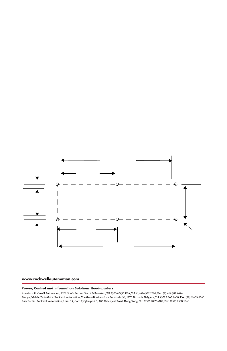
Panel Cutout Dimensions
All dimensions are in millibeters (inches)
4.8 (0.19)
Cutout
173.0 (6.81)
Cutout
88.9
(3.50)
176.3 (6.95)
4.8 (0.19)
Cutout 345.9 (13.62)
2706-P22R Display
352.3 (13.87)
98.4
(3.88)
6.4 (0.25)
Diameter
Hole
6 places
Publication 2706-IN020A-EN-P - January 2004 PN 41061-345-01(1)
Supersedes Publication XXXX-X.X.X - Month Year Copyright © 2004 Rockwell Automation, Inc. All rights reserved. Printed in the U.S.A.
 Loading...