

Page 1

InView Marquee
Message Display
2706-P22R, 2706-P42, 2706-P43,
2706-P44, 2706-P72, 2706-P74,
2706-P92, 2706-P94
User Manual
Page 2
Important User Information
Solid state equipment has operational characteristics differing from those of
electromechanical equipment. Safety Guidelines for the Application,
Installation and Maintenance of Solid State Controls (publication SGI-1.1
available from your local Rockwell Automation sales office or online at
http://literature.rockwellautomation.com
differences between solid state equipment and hard-wired electromechanical
devices. Because of this difference, and also because of the wide variety of
uses for solid state equipment, all persons responsible for applying this
equipment must satisfy themselves that each intended application of this
equipment is acceptable.
In no event will Rockwell Automation, Inc. be responsible or liable for
indirect or consequential damages resulting from the use or application of
this equipment.
The examples and diagrams in this manual are included solely for illustrative
purposes. Because of the many variables and requirements associated with
any particular installation, Rockwell Automation, Inc. cannot assume
responsibility or liability for actual use based on the examples and diagrams.
No patent liability is assumed by Rockwell Automation, Inc. with respect to
use of information, circuits, equipment, or software described in this manual.
Reproduction of the contents of this manual, in whole or in part, without
written permission of Rockwell Automation, Inc., is prohibited.
Throughout this manual, when necessary, we use notes to make you aware
of safety considerations.
) describes some important
WARNING
IMPORTANT
ATTENTION
SHOCK HAZARD
BURN HAZARD
Identifies information about practices or circumstances that can cause
an explosion in a hazardous environment, which may lead to personal
injury or death, property damage, or economic loss.
Identifies information that is critical for successful application and
understanding of the product.
Identifies information about practices or circumstances that can lead
to personal injury or death, property damage, or economic loss.
Attentions help you identify a hazard, avoid a hazard, and recognize
the consequence
Labels may be located on or inside the equipment, for example, a drive
or motor, to alert people that dangerous voltage may be present.
Labels may be located on or inside the equipment, for example, a drive
or motor, to alert people that surfaces may be dangerous
temperatures.
Page 3

Summary of Changes
This document describes the InView Marquee Message Display.
Revision bars in the margin identify updated information. Changes for
this version of the document include:
Change Page
Updated information on how to change the serial address 1-2
Added information about how to use the 2706-PCABLE1 to
download a message application
Added information about the communication module when
you set the IP address.
1-27
2-11
1 Publication 2706-UM016D-EN-P - March 2006
Page 4

2 Summary of Changes
Publication 2706-UM016D-EN-P - March 2006
Page 5

Install InView Marquee Message
Display
Table of Contents
Chapter 1
Introduction . . . . . . . . . . . . . . . . . . . . . . . . . . . . . . . . . . . 1-1
Wire and Safety Guidelines . . . . . . . . . . . . . . . . . . . . . . . . 1-1
Change the Serial Address . . . . . . . . . . . . . . . . . . . . . . . . . 1-2
Checkout Procedure . . . . . . . . . . . . . . . . . . . . . . . . . . . . . 1-2
Electrical Connections for 2706-P42, 2706-P43 and
2706-P44 Displays . . . . . . . . . . . . . . . . . . . . . . . . . . . . . . . 1-2
Mount the 2706-P42, 2706-P43 and 2706-P44 Displays . . . . 1-6
Wall Mount . . . . . . . . . . . . . . . . . . . . . . . . . . . . . . . . . 1-7
Ceiling Mount . . . . . . . . . . . . . . . . . . . . . . . . . . . . . . . 1-9
Stack Mount . . . . . . . . . . . . . . . . . . . . . . . . . . . . . . . . 1-10
Back-to-back Mount. . . . . . . . . . . . . . . . . . . . . . . . . . . 1-11
Mount the 2706-P72 and 2706-P74 series NEMA 4
and 4x models . . . . . . . . . . . . . . . . . . . . . . . . . . . . . . . . . 1-13
Electrical Connections for 2706-P72 and 2706-P74 Signs . . . 1-14
Mount the 2706-P92C and 2706-P94C Sign . . . . . . . . . . . . . 1-17
Back-to-back Mount. . . . . . . . . . . . . . . . . . . . . . . . . . . 1-19
Electrical Connections for 2706-P92C and 2706-P94C Signs . 1-19
Mount the 2706-P22R Display . . . . . . . . . . . . . . . . . . . . . . 1-23
Panel Cutout Dimensions for 2706-P22R Display . . . . . . 1-23
Dimensions for 2706-P22R Display . . . . . . . . . . . . . . . . 1-24
Electrical Connections for 2706-P22R Display . . . . . . . . . . . 1-24
Communication Connections for 2706-P22R Display . . . . . . 1-25
DIP Switch Settings for 2706-P22R Display . . . . . . . . . . . . . 1-26
Download a Message Application . . . . . . . . . . . . . . . . . . . 1-27
RS-232 to RS-485 Networking. . . . . . . . . . . . . . . . . . . . . . . 1-27
RS-485 Echo . . . . . . . . . . . . . . . . . . . . . . . . . . . . . . . . . . . 1-28
Global Addressing . . . . . . . . . . . . . . . . . . . . . . . . . . . . 1-29
Ground and Terminate the RS-485 Network . . . . . . . . . . . . 1-29
Chapter 2
InView System Connectivity
i Publication 2706-UM016D-EN-P - March 2006
Serial ASCII Communications. . . . . . . . . . . . . . . . . . . . . . . 2-1
Features . . . . . . . . . . . . . . . . . . . . . . . . . . . . . . . . . . . . . . 2-1
2706-P42, 2706-P43, 2706-P44, 2706-P72, and 2706-P74
Displays . . . . . . . . . . . . . . . . . . . . . . . . . . . . . . . . . . . 2-1
2706-P22 Display . . . . . . . . . . . . . . . . . . . . . . . . . . . . . 2-2
Dip Switch Information for the 2706-P9x . . . . . . . . . . . . . . 2-4
Switch 1 . . . . . . . . . . . . . . . . . . . . . . . . . . . . . . . . . . . 2-4
Switch 2 . . . . . . . . . . . . . . . . . . . . . . . . . . . . . . . . . . . 2-5
Additional Information for 2706-P9x Displays . . . . . . . . 2-6
Power-up Messages. . . . . . . . . . . . . . . . . . . . . . . . . . . . . . 2-10
2706-P42, 2706-P43, 2706-P44, 2706-P72, 2706-P74,
2706-P92, and 2706-P94 Displays . . . . . . . . . . . . . . . . . 2-10
2706-P22: Display . . . . . . . . . . . . . . . . . . . . . . . . . . . . 2-10
Display Setup . . . . . . . . . . . . . . . . . . . . . . . . . . . . . . . . . . 2-11
Set the IP Address. . . . . . . . . . . . . . . . . . . . . . . . . . . . . . . 2-11
Page 6

ii Table of Contents
Serial ASCII Communications
Gateway Address and Subnet Mask Setup . . . . . . . . . . . 2-15
Create the Message File. . . . . . . . . . . . . . . . . . . . . . . . . . . 2-16
Attach a Note to a Message . . . . . . . . . . . . . . . . . . . . . 2-17
Text Color . . . . . . . . . . . . . . . . . . . . . . . . . . . . . . . . . . 2-17
Date, Time and Variables . . . . . . . . . . . . . . . . . . . . . . . 2-17
Category . . . . . . . . . . . . . . . . . . . . . . . . . . . . . . . . . . . 2-18
Message Priorities . . . . . . . . . . . . . . . . . . . . . . . . . . . . 2-18
Pause . . . . . . . . . . . . . . . . . . . . . . . . . . . . . . . . . . . . . 2-19
Message Header. . . . . . . . . . . . . . . . . . . . . . . . . . . . . . 2-19
Preview Messages . . . . . . . . . . . . . . . . . . . . . . . . . . . . 2-19
Set the Display Address . . . . . . . . . . . . . . . . . . . . . . . . 2-19
Download Messages . . . . . . . . . . . . . . . . . . . . . . . . . . 2-20
Clear Memory/Message Queue . . . . . . . . . . . . . . . . . . 2-22
Chapter 3
Use a PLC5 out Channel Zero . . . . . . . . . . . . . . . . . . . . . . 3-1
Use an SLC 5/03, 5/04, or 5/05 out Channel Zero . . . . . . . . 3-2
Use a MicroLogix out Channel Zero or One . . . . . . . . . . . . 3-3
Use ControlLogix Processor out Channel Zero . . . . . . . . . . 3-4
Use the CompactLogix Processor out Channel Zero or One 3-5
Use FlexLogix Processor out Channel Zero. . . . . . . . . . . . . 3-6
InView Protocol
Chapter 4
Introduction . . . . . . . . . . . . . . . . . . . . . . . . . . . . . . . . . . . 4-1
Trigger Messages and Update Variables . . . . . . . . . . . . . . . 4-1
The CTRL-T Function Frame. . . . . . . . . . . . . . . . . . . . . 4-1
The CTRL-V Function Frame - Numeric Variables . . . . . 4-3
The CTRL-V Function Frame - Alphanumeric Variables . 4-4
Examples of the Control-T Function. . . . . . . . . . . . . . . . . . 4-5
Trigger a Message on all Displays using
Priority Messaging . . . . . . . . . . . . . . . . . . . . . . . . . . . . 4-5
Trigger a Message on a Specific Display using Priority
Messaging . . . . . . . . . . . . . . . . . . . . . . . . . . . . . . . . . . 4-6
Add a Message on all Displays . . . . . . . . . . . . . . . . . . . 4-7
Adding a Message on a Specific Display . . . . . . . . . . . . 4-7
Remove all Messages on all Displays . . . . . . . . . . . . . . 4-7
Remove all Messages on a Specific Display . . . . . . . . . . 4-8
Remove a Message on a Specific Display . . . . . . . . . . . 4-9
Examples of the Control-V Function. . . . . . . . . . . . . . . . . . 4-9
Update a Variable on all Displays . . . . . . . . . . . . . . . . . 4-9
Update Variable on a Specific Display . . . . . . . . . . . . . 4-10
Modbus ASCII Protocol to Download and
Preview Messages . . . . . . . . . . . . . . . . . . . . . . . . . . . . . . . 4-10
How InView Sign Communication Protocol is used
with Modbus ASCII Protocol . . . . . . . . . . . . . . . . . . . . . . . 4-11
Publication 2706-UM016D-EN-P - March 2006
Page 7

Table of Contents iii
Mode of Transmission . . . . . . . . . . . . . . . . . . . . . . . . . 4-12
InView Display Memory Map . . . . . . . . . . . . . . . . . . . . 4-12
Methods of Transmission . . . . . . . . . . . . . . . . . . . . . . . 4-13
Message Format. . . . . . . . . . . . . . . . . . . . . . . . . . . . . . 4-14
Longitudinal Redundancy Check (LRC) Error
Detection and Calculation . . . . . . . . . . . . . . . . . . . . . . 4-16
Examples of Modbus ASCII Functions . . . . . . . . . . . . . . . . 4-17
Heartbeat Function . . . . . . . . . . . . . . . . . . . . . . . . . . . 4-18
Clear the Display Memory . . . . . . . . . . . . . . . . . . . . . . 4-20
Clear the Message Queue using Modbus ASCII
in Broadcast Mode (Recommended) . . . . . . . . . . . . . . . 4-20
Clear the Message Queue using Modbus ASCII in
Guaranteed Mode . . . . . . . . . . . . . . . . . . . . . . . . . . . . 4-21
Set Time in Broadcast Mode with AM/PM Format . . . . . 4-21
Set Time in Broadcast Mode with 24 Hour Format. . . . . 4-22
Set Day and Date in Broadcast Mode . . . . . . . . . . . . . . 4-23
Preview a Message. . . . . . . . . . . . . . . . . . . . . . . . . . . . 4-25
Download Messages . . . . . . . . . . . . . . . . . . . . . . . . . . 4-27
Add/Remove a Message using a Modbus ASCII 10
Frame Query (Recommended) . . . . . . . . . . . . . . . . . . . 4-33
Add/Remove a Message using Modbus ASCII 10
Frame Transmission . . . . . . . . . . . . . . . . . . . . . . . . . . . 4-33
Priority Messaging using a Modbus ASCII Query
(Recommended) . . . . . . . . . . . . . . . . . . . . . . . . . . . . . 4-34
Priority Messaging using a Modbus ASCII Transmission . 4-35
Update a Variable using a Modbus ASCII 06 Frame in
Broadcast Mode (Recommended) . . . . . . . . . . . . . . . . . 4-35
Update a Variable using a Modbus ASCII 06 Frame in
Guaranteed Mode . . . . . . . . . . . . . . . . . . . . . . . . . . . . 4-36
Update Variables using a Modbus ASCII 10 frame
in Broadcast mode (Recommended) . . . . . . . . . . . . . . . 4-36
Update Variables using a Modbus ASCII 10 frame in
Guaranteed mode . . . . . . . . . . . . . . . . . . . . . . . . . . . . 4-37
Read the Message Queue using a Modbus ASCII 03
frame . . . . . . . . . . . . . . . . . . . . . . . . . . . . . . . . . . . . . 4-38
Read Variables in a Display using a Modbus ASCII 03
frame . . . . . . . . . . . . . . . . . . . . . . . . . . . . . . . . . . . . . 4-39
Change the InView Display Address . . . . . . . . . . . . . . . 4-40
InView Display Communication Protocol Functions and
Descriptions . . . . . . . . . . . . . . . . . . . . . . . . . . . . . . . . . . . 4-41
InView Message Format used within Modbus ASCII
Protocol . . . . . . . . . . . . . . . . . . . . . . . . . . . . . . . . . . . 4-41
Special Function Command . . . . . . . . . . . . . . . . . . . . . 4-45
Text Position Placement . . . . . . . . . . . . . . . . . . . . . . . . 4-51
ASCII Characters . . . . . . . . . . . . . . . . . . . . . . . . . . . . . . . . 4-52
Reference Material. . . . . . . . . . . . . . . . . . . . . . . . . . . . . . . 4-52
Publication 2706-UM016D-EN-P - March 2006
Page 8

iv Table of Contents
InView Control and
InView Control API
Specifications
Catalog Number Explanation
Temperature Protection in
NEMA-Rated Enclosures
Chapter 5
Introduction . . . . . . . . . . . . . . . . . . . . . . . . . . . . . . . . . . . 5-1
Quick Overview . . . . . . . . . . . . . . . . . . . . . . . . . . . . . . . . 5-1
Reference . . . . . . . . . . . . . . . . . . . . . . . . . . . . . . . . . . . . . 5-2
Properties . . . . . . . . . . . . . . . . . . . . . . . . . . . . . . . . . . . . . 5-3
Methods . . . . . . . . . . . . . . . . . . . . . . . . . . . . . . . . . . . . . . 5-7
Appendix A
2706-P43, 2706-P42, 2706-P44, 2706-P72 Specifications . . . . A-1
2706-P92, 2706-P94 Specifications . . . . . . . . . . . . . . . . . . . A-2
2706-P22R Specifications . . . . . . . . . . . . . . . . . . . . . . . . . . A-3
Appendix B
Appendix C
Index
Publication 2706-UM016D-EN-P - March 2006
Page 9

Chapter
Install InView Marquee Message Display
1
Introduction
Wire and Safety Guidelines
These instructions show how to change the serial address and how to
mount InView series signs with NEMA Types 4, 4X, and 12 enclosures.
These signs are intended for indoor use only. Type 4 enclosures are
intended to provide a degree of protection against windblown dust
and rain, splashing water, and hose-directed water. Type 4X
enclosures are intended to provide a degree of protection against
corrosion, windblown dust and rain, splashing water, and
hose-directed water. Type 12 enclosures are in a sealed case that is,
dust free, gasketing, and spray down resistant.
Install the InView display conforming to NFPA 70E, Electrical Safety
Requirements for Employee Workplaces. In addition to the NFPA
general guidelines, refer to the following.
• Careful cable routing helps minimize electrical noise. Route
incoming power to the module by a separate path from the
communication cables.
TIP
Do not run communications wiring and power
wiring in the same conduit!
• Where communication and wire paths must cross, make their
intersection perpendicular.
• Grounding helps limit the effects of noise due to
electromagnetic interference (EMI). To avoid problems caused
by EMI, properly ground all equipment and use shielded cables.
WARNING
1 Publication 2706-UM016D-EN-P - March 2006
EXPLOSION HAZARD
Do not connect or disconnect equipment unless
power has been switched off and area is known to
be non-hazardous.
Page 10

1-2 Install InView Marquee Message Display
Change the Serial Address
Checkout Procedure
IMPORTANT
A serial address for an InView sign is a number from 1 to 254 in
hexadecimal (01 to FE). All signs leave the factory with a default
address of 1 or 01.
This serial address is resident in the InView display and is used for
RS485 networking. If one of the factory network communications
modules are used (2706-Pxxxx), this serial address is typically left at
its factory default and the network node or IP address is set in the
factory network communication module.
After you install a sign according to the Electrical and Mounting
Instructions, make sure the sign is installed properly by applying
power to it. The following information should be displayed on the
sign.
Power wiring must be in accordance with Class I,
Class II and Class III Division 2 wiring methods
(Articles 501-4(b), 502-4(b) and 503-3(b) of the
National Electrical Code, NFPA70) and in
accordance with the local authority having
jurisdiction.
Electrical Connections for 2706-P42, 2706-P43 and 2706-P44 Displays
• Firmware part number and version letter (xxxx).
• Amount of RAM in the sign, (256K).
• Serial address of the sign (a number from 01 to FE or from 1 to
254).
WARNING
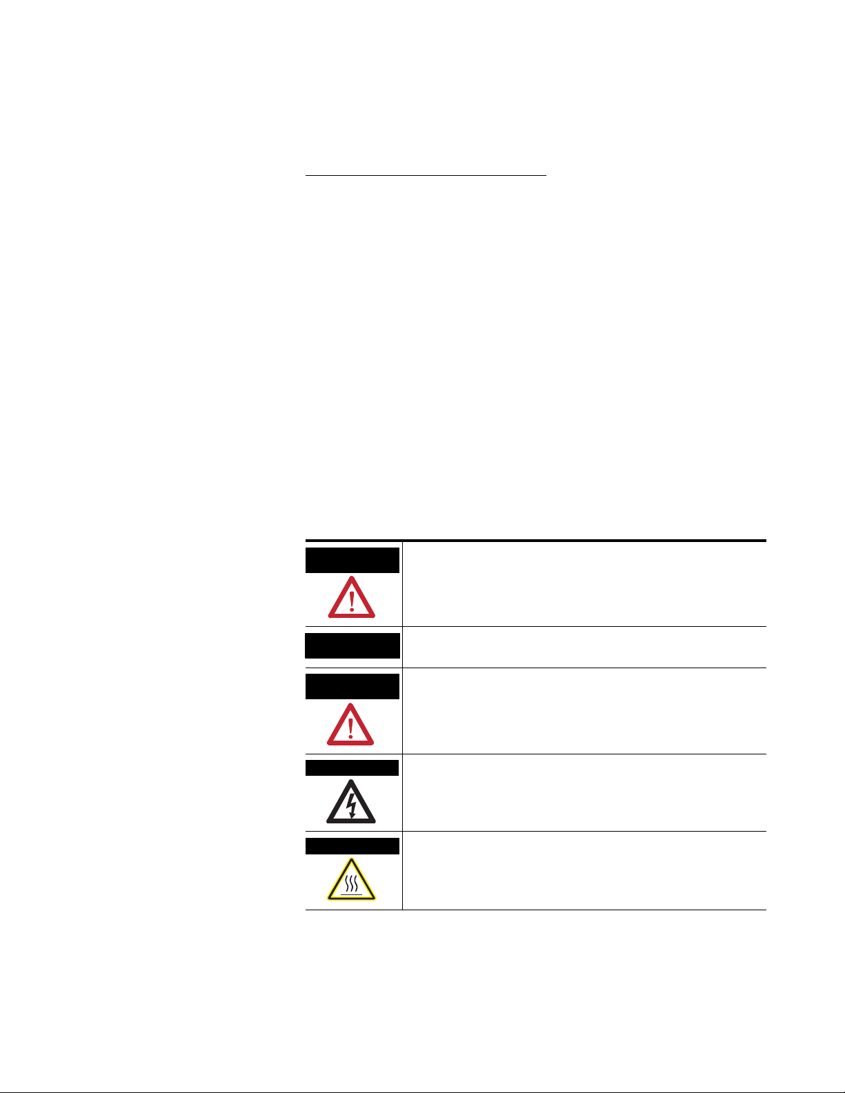
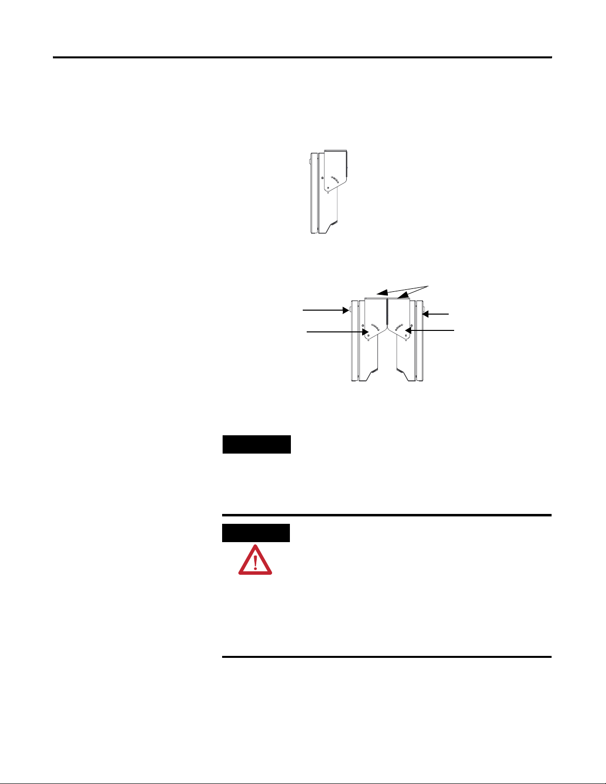
To connect the 2706-P42, 2706-P43, and 2706-P44 displays:
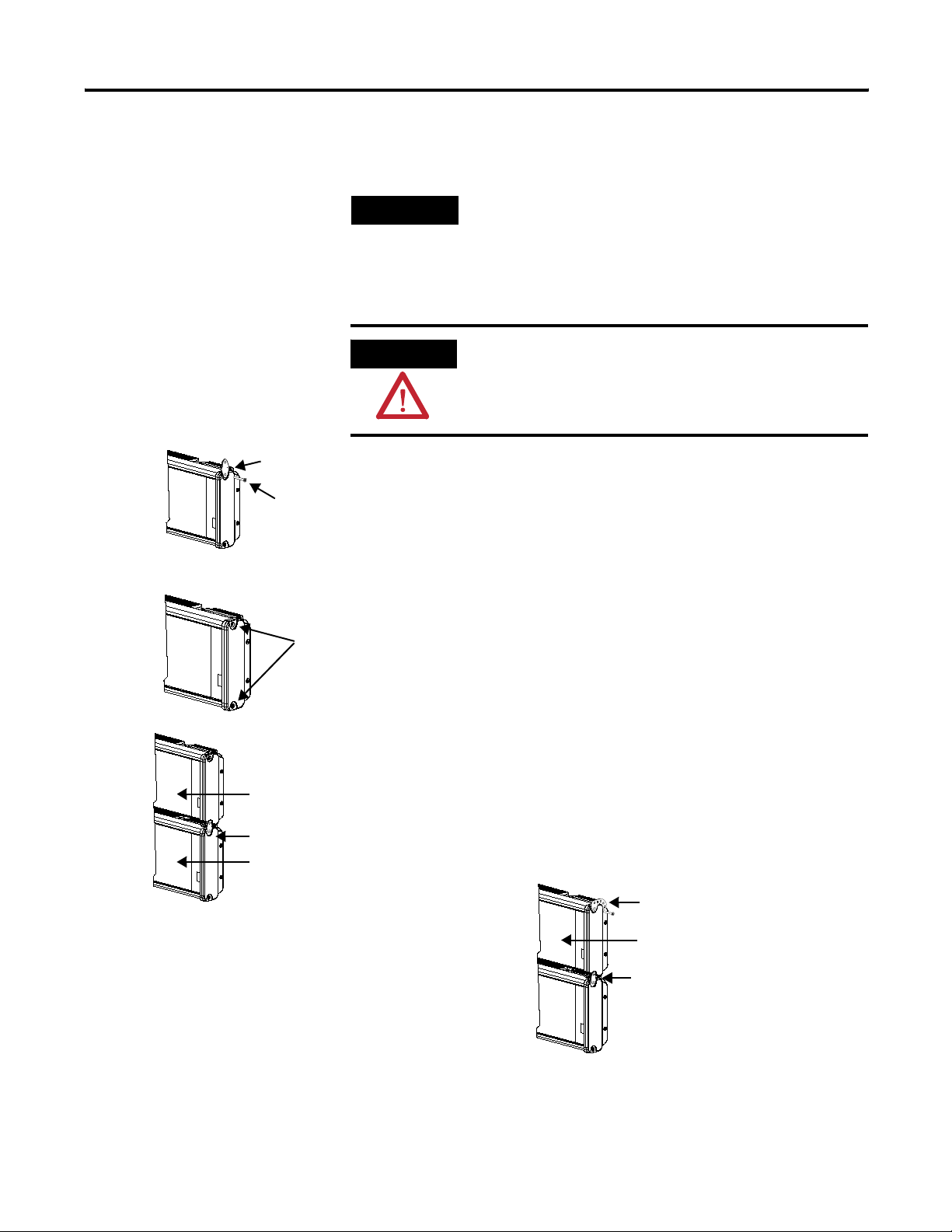
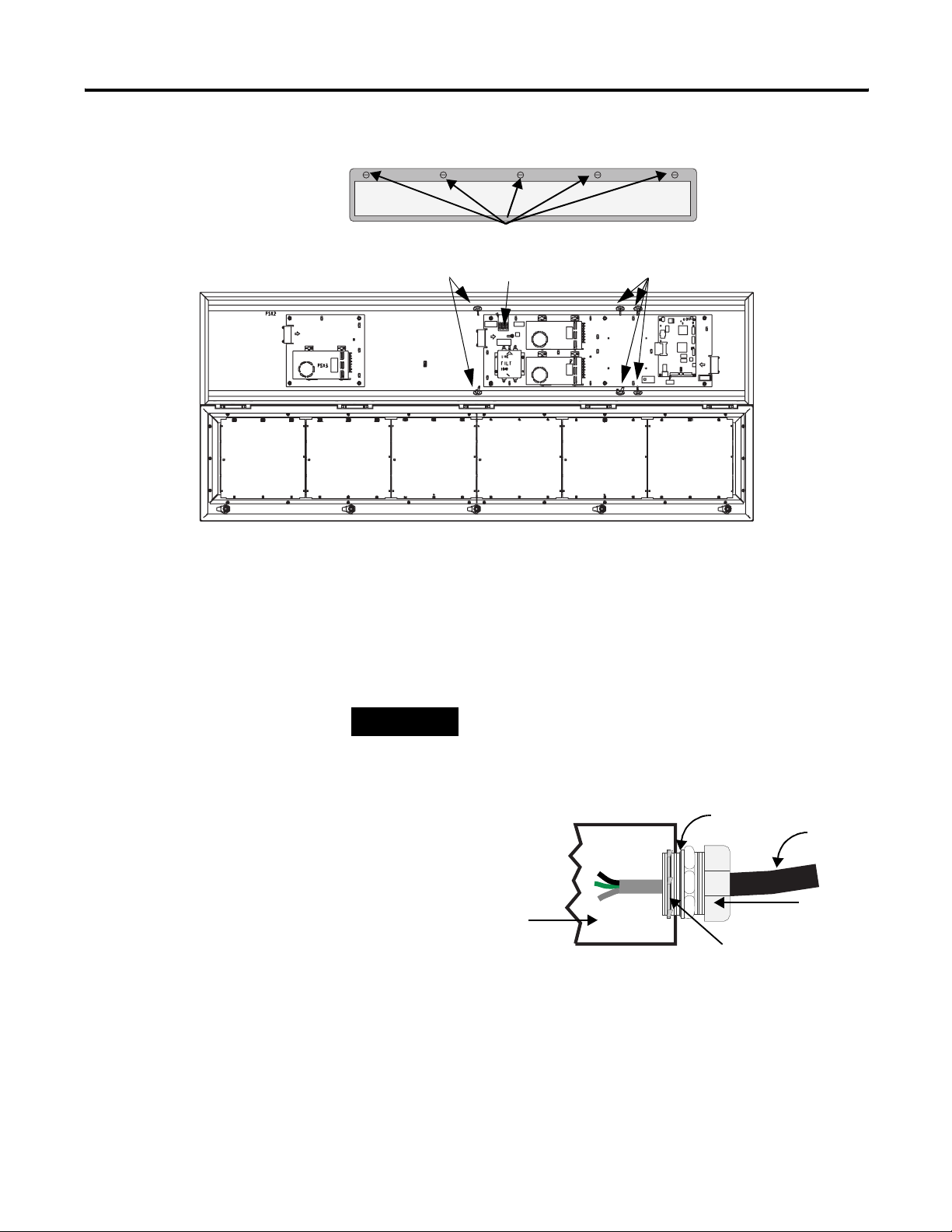
1. Remove the power supply cover by unscrewing its 6 screws.
Save the screws for a later step.
Hazardous voltage. Contact with high voltage may
cause death or serious injury. Always disconnect
power to sign prior to servicing.
Publication 2706-UM016D-EN-P - March 2006
Page 11
Install InView Marquee Message Display 1-3
Hole plugs,
bottom, removed
Hole plugs,
top, removed
Wing nuts for
hole plugs
TIP
It is recommended that you install power and
serial wires at the bottom of the power supply
enclosure to reduce noise from power wires
crossing serial wires.
You can install the power or serial wires at the
top of the enclosure if necessary.
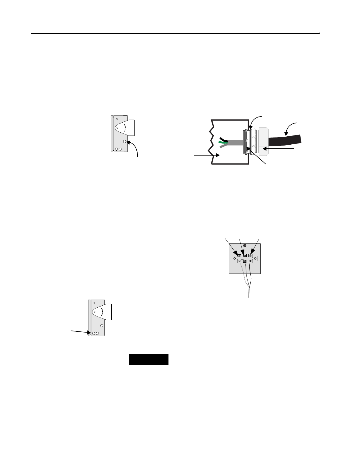
2. Remove the left or right conduit hole plug from the top of the
enclosure by removing its wing nut inside the enclosure.
Save the hole plug for a later step.
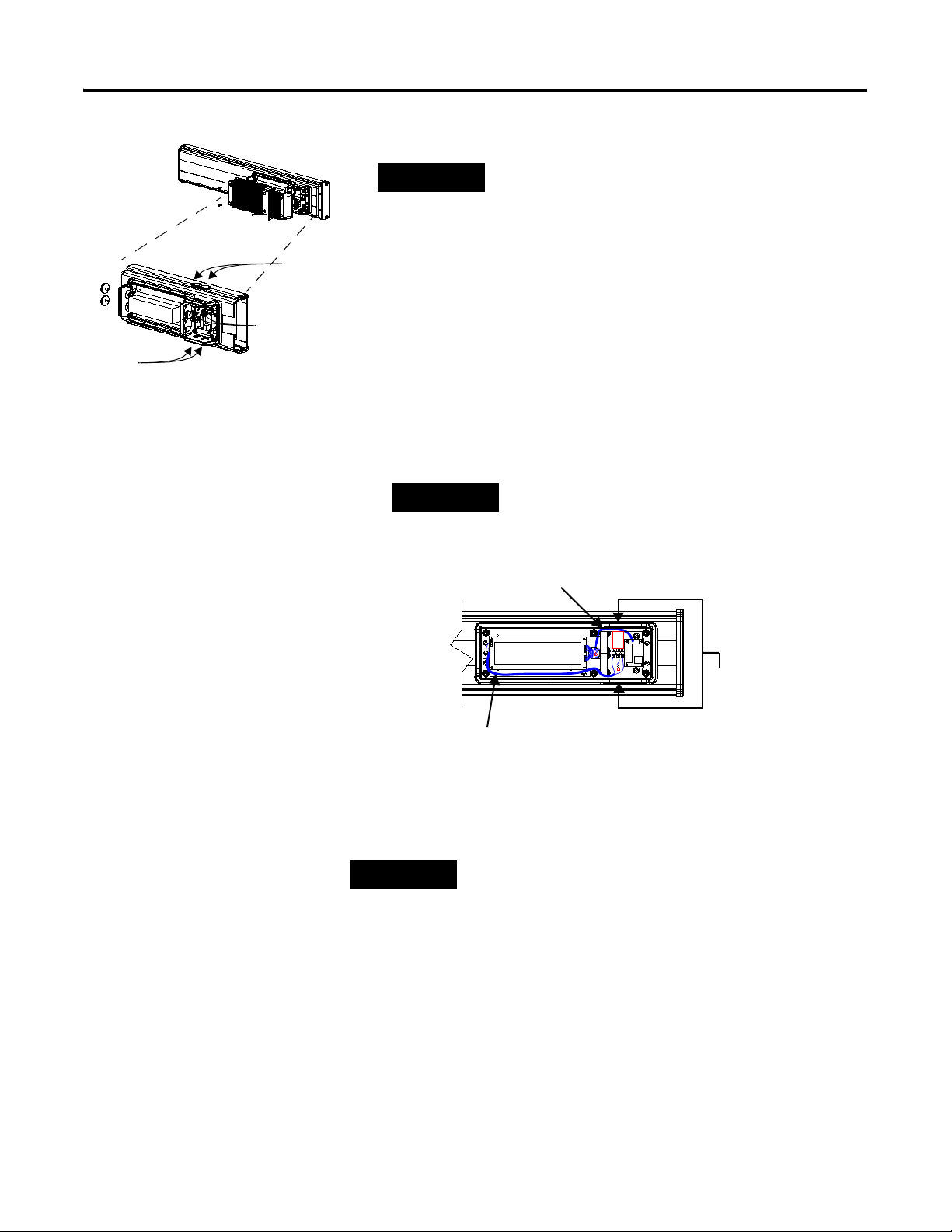
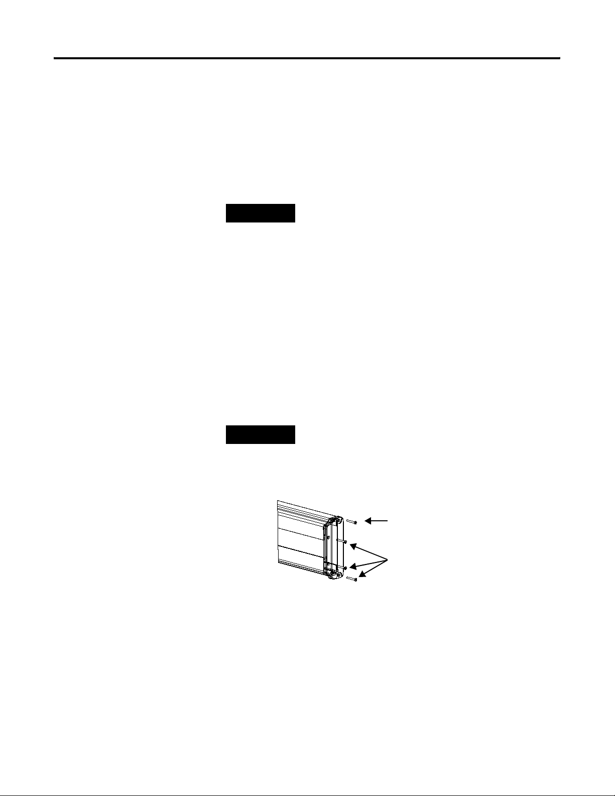
3. Insert the power wires through the left conduit hole on either
the top or the bottom of the sign.
TIP
Use watertight conduit connectors only.
Flexible conduit should be used.
Internal
serial wires
Insert the
power wires
into one of
Internal wiring for
power supply
these
conduits.
4. Strip the wires back 6.35 mm (1/4 in.). Connect the incoming
electrical wires.
TIP
Be sure to place the wires so they are not caught by
screws when replacing the power supply cover, and
also so they do not interfere with fan operation.
Publication 2706-UM016D-EN-P - March 2006
Page 12
1-4 Install InView Marquee Message Display
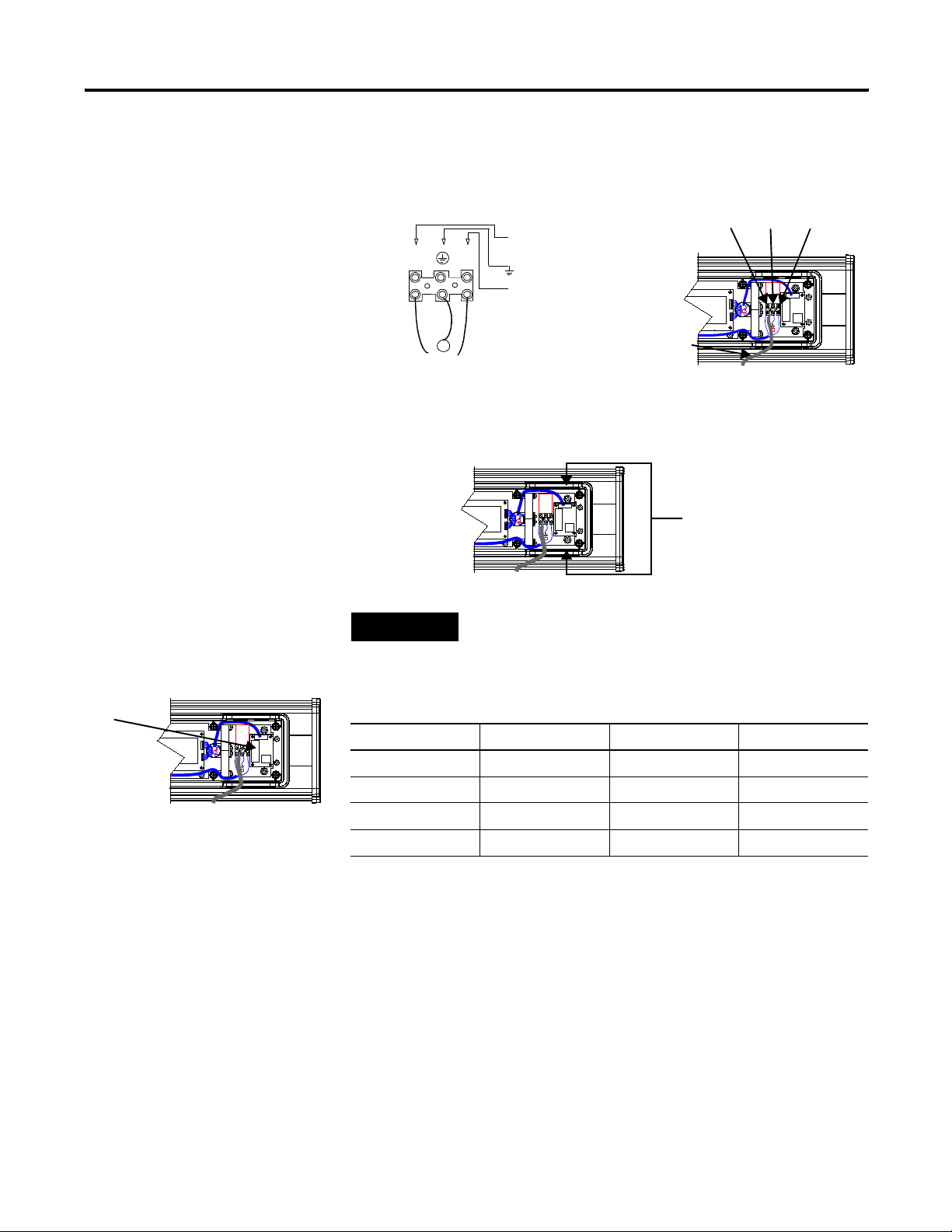
Line
(Hot)
BLACK
Hot (Line 1)
H
N
Ground
Neutral
(Line 2)
Ground
GREEN
w/
Yel low
Neutral
(Line 2):
WHITE
100 to 240V ac
@ 50/60 Hz
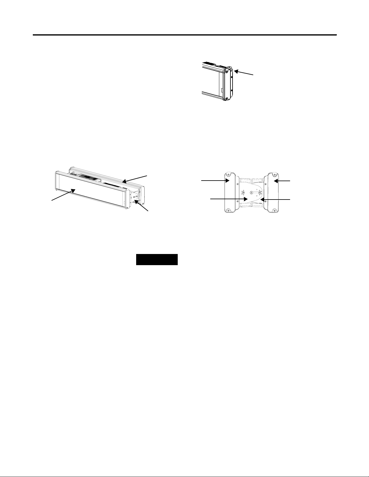
5. Insert the serial wires through the right conduit hole on either
the top or the bottom of the sign.
Insert the
serial wires
into one of these
conduit holes.
TB1
TIP
TB1 can be used for incoming serial connection for
RS-232 or RS-485.
TB1 - Full
Pin Pin Name Pin Pin Name
1. GND 5. RS-485(+)
2. +5V 6. RS-485(-)
3. RS-232 TX 7. NC
4. RS-232 RX 8. SHIELD
6. Connect the incoming serial wires.
Publication 2706-UM016D-EN-P - March 2006
Page 13
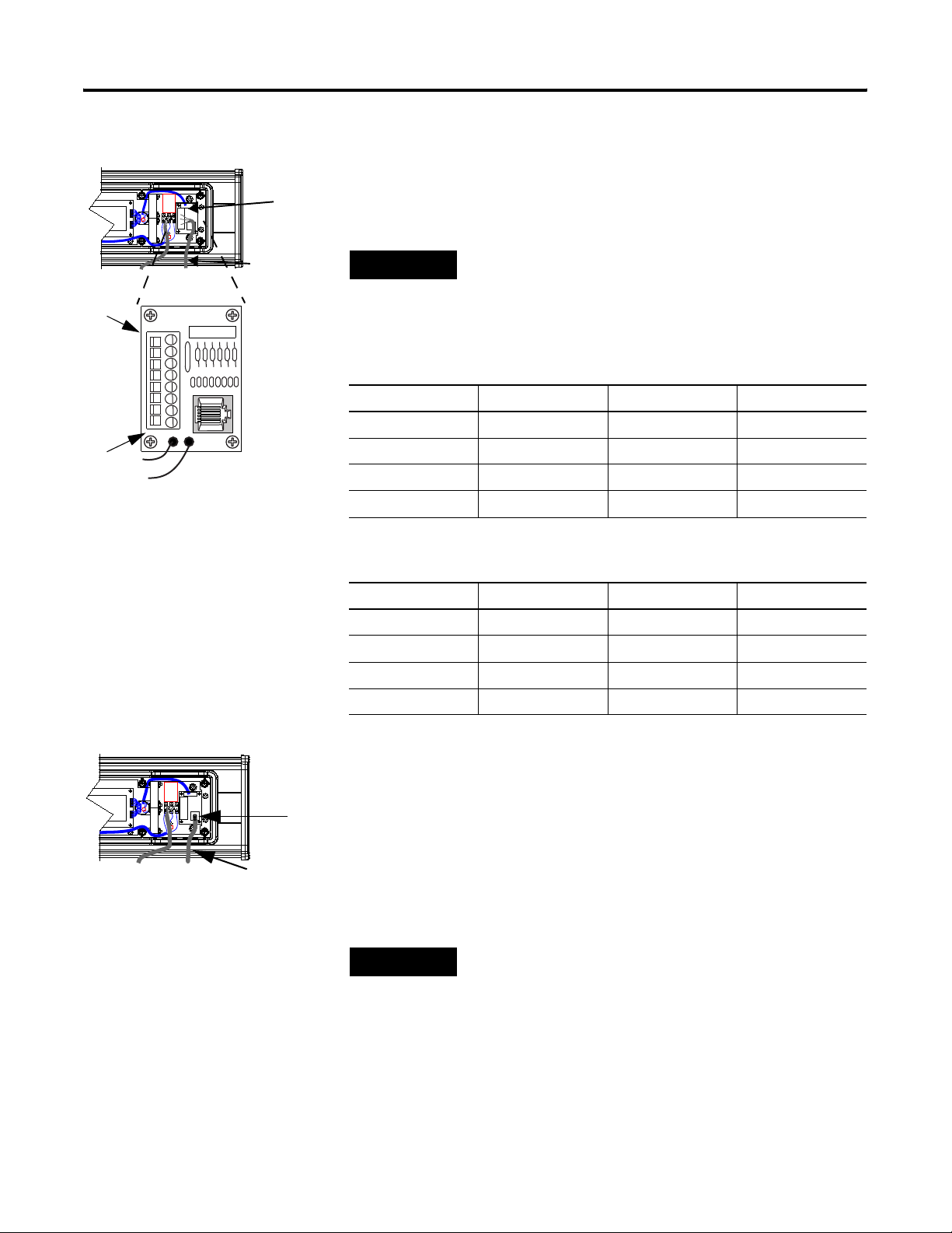
TB1
Install InView Marquee Message Display 1-5
TB1 can be used for incoming RS-232 or RS-485 serial
connection. They cannot be connected at the same time. RS-485
is recommended to reduce undesirable electrical interference.
Incoming serial
wires
TIP
Be sure to place the wires so they are not caught by
screws when replacing the power supply cover, and
also so they do not interfere with fan operation.
8
7
6
5
4
3
2
1
TB1 - RS-232
Pin Pin Name Pin Pin Name
1. GND 5. NC
2. NC 6. NC
3. RS-232 TX 7. NC
4. RS-232 RX 8. NC
TB1 - RS-485
Pin Pin Name Pin Pin Name
1. NC 5. RS-485(+)
2. NC 6. RS-485(-)
3. NC 7. NC
4. NC 8. SHIELD
P1
Incoming
serial wires
7. P1 can be used for incoming RS-232 only, although it is optional
and not recommended.
P1 is intended for RS-232 application downloads and RS-485
terminating resistor connection.
See publication 2706-IN007 for more information on RS-485
termination.
TIP
Be sure to place the wires so they are not caught by
screws when replacing the power supply cover, and
also so they do not interfere with fan operation.
8. To maintain NEMA compliance and to prevent EMI emissions,
install hole plugs in any open conduit holes in the power supply
enclosure.
Publication 2706-UM016D-EN-P - March 2006
Page 14
1-6 Install InView Marquee Message Display
Mount the 2706-P42, 2706-P43 and 2706-P44 Displays
If needed, there is an extra hole plug supplied in addition to any
hole plugs removed in Step 2 on page 3.
9. Replace the power supply cover using the 6 screws from when
the cover was removed.
10. Torque the screws to 2.7 Nm (24 lb-in).
11. Connect the power cable to a power source.
TIP
Only qualified personnel should install the InView
signs.
InView signs are for indoor use only and should not
be continuously exposed to direct sunlight.
Mounting hardware that is used to hang or suspend
signs must be capable of supporting at least 4 times
the total weight of any/all signs mounted together.
For integrity of the case, do not drill holes in or
modify the case.
Disconnect power before you mount a sign.
WARNING
Hazardous voltage. Contact with high voltage may
cause death or serious injury. Always disconnect
power to sign prior to servicing.
Publication 2706-UM016D-EN-P - March 2006
Page 15
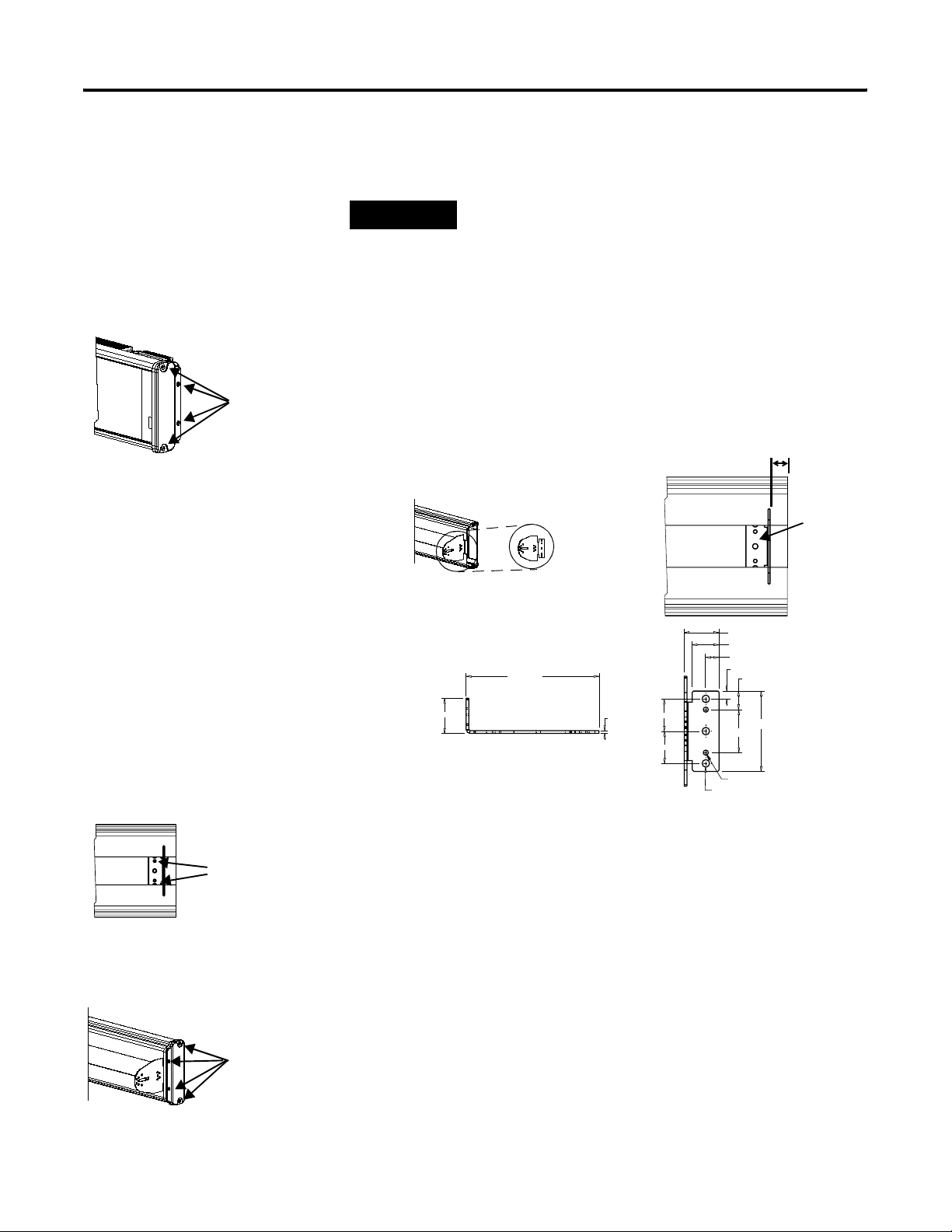
Wall Mount
Install InView Marquee Message Display 1-7
Remove
these
screws.
TIP
Remove only one end cap at a time.
To mount the display to a wall:
1. Remove the 4 screws and the end cap from one end of the sign.
2. Slide one of the wall mounting brackets onto the back of the
sign until it is approximately 13 mm (0.5 in.) away from the end
of the sign.
0.5”
Wall mounting
bracket
127 (5.00)
33.13 (1.30)
25.40 (1.00)
12.70 (0.50)
7.62 (0.30)
17.65 (0.70)
Wall
mounting
bracket
Phillips
screws go
here.
Fasten
these
screws.
33.13 (1.305)
Dimensions are in mm (inches).
2.65 (0.105)
30.35 (1.195)
30.35 (1.195)
75.95 (2.99)
40.64 (1.60)
4.04 (0.159) 10- 32 UNC-2B 2 Holes
7.11 (0.280) Thru 3 Holes
3. Use two 10-32 x 1/4 Phillips screws (supplied) to secure the wall
mounting bracket to the back of the sign.
4. Torque the screws to 2.7 Nm (24 lb-in).
5. Replace the end cap using the 4 screws removed in Step 1
above.
6. Torque the screws to 2.7 Nm (24 lb-in).
7. Repeat Steps 1 to 6 for the other end of the sign.
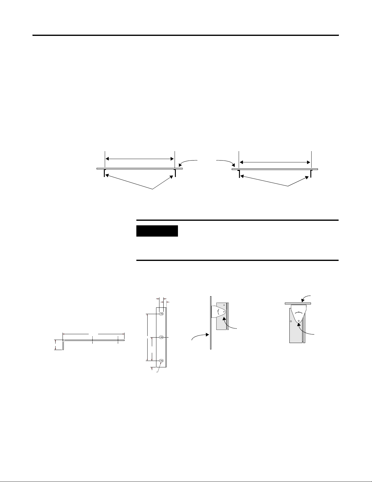
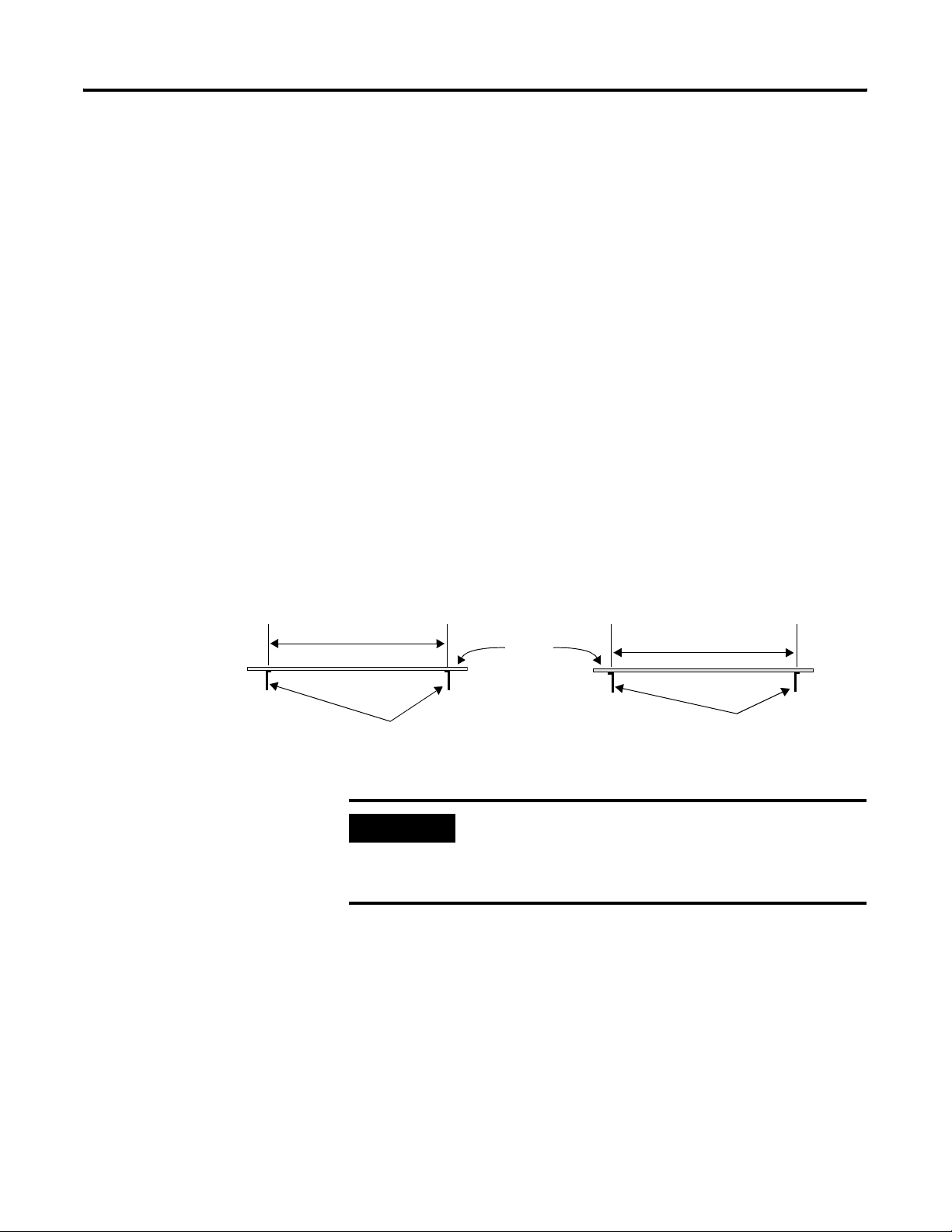
Approximate distances between the bracket holes,
center-to-center, are shown below.
Publication 2706-UM016D-EN-P - March 2006
Page 16
1-8 Install InView Marquee Message Display
94 cm (37 in.) for 2706-P42
183 cm (72.2 in.) for 2706-P43
185.4 cm (73 in.) for 2706-P44
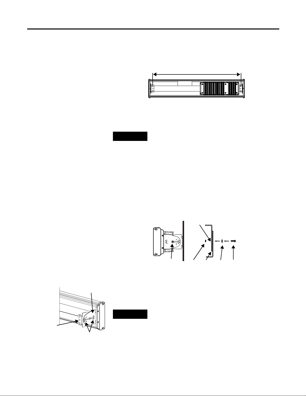
8. Attach the two remaining wall mounting brackets to a wall so
that they align with the brackets on the sign.
Mounting bracket
on the sign
TIP
Do not install the sign directly to drywall or
plaster-board. The sign must be fastened to a wall
capable of supporting at least four times the weight
of the sign.
9. Connect the mounting brackets on each end of the sign together
using a 5/16 Phillips screw and a 5/16 washer through the
mounting holes, as shown below, securing with a 5/16 nut.
Do not tighten the nut at this time.
Screw and
washer through
mounting holes
Mounting
holes
Nut
Brackets
Top viewSide view
Washer Screw
10. Match the alignment holes of the brackets on the sign with the
alignment holes of the brackets on the wall so that the sign is at
the desired viewing angle.
Mounting
bracket on the
wall
Publication 2706-UM016D-EN-P - March 2006
Alignment holes
TIP
The second mounting bracket is shown here for
illustration only. It is actually mounted to the wall.
11. Fasten the mounting brackets together using two 10-32 x 3/4
Phillips screws, two 10-32 washers, and two 10-32 lock nuts
through selected alignment holes on each end of the sign.
12. Torque to 2.7 Nm (24 lb-in).
Page 17
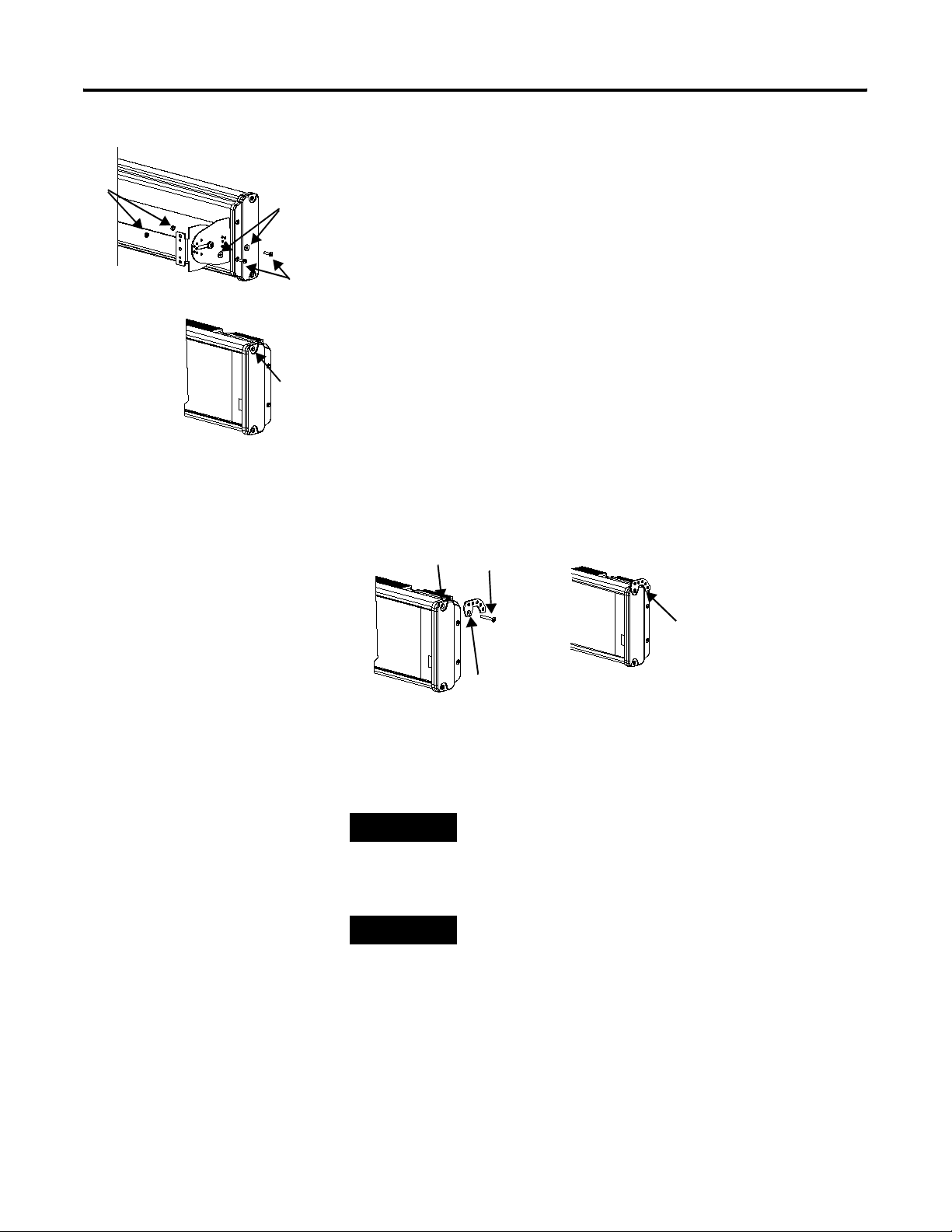
Lock
nuts
Install InView Marquee Message Display 1-9
13. Torque the 5/16 nuts in the mounting holes (See Step 9) to
2.7 Nm (24 lb-in).
Washers
Ceiling Mount
Phillips
screws
To mount the display to the ceiling:
1. Remove one screw from the top of the end cap.
Remove
this screw.
2. Line up a ceiling bracket with the top hole on the sign’s end cap
so the bracket fits in the indentation.
There are left and right ceiling brackets. Use the one that fits
with the screw hole’s countersunk side facing out.
3. Secure the ceiling bracket with the screw removed in Step 1 and
torque the screw to 2.7 Nm (24 in-lb).
Screw hole
Screw
Ceiling
bracket
Ceiling
bracket
mounted to
end cap.
4. Repeat steps 1 through 3 for the other end of the sign.
5. Use chains (not supplied) to hang the sign from a ceiling.
TIP
TIP
Use chains capable of supporting 4 times the total
weight of the sign(s).
The hole you select in the ceiling bracket for the
chain determines the angle at which the sign hangs.
Publication 2706-UM016D-EN-P - March 2006
Page 18
1-10 Install InView Marquee Message Display
Stack Mount
Stacking
bracket
Screw
Remove
these
screws.
TIP
Up to 4 signs can be hung together vertically
(‘stacked’). Mounting system for stack mounting must
support a minimum of four times the total weight of
all signs being stacked.
WARNING
Possible crush hazard. Do not stack more than 4
signs. Otherwise signs may fall causing serious injury
or death.
To stack the signs:
1. Remove the top screw from each end cap of the bottom sign
2. Use the screw removed in Step 1 to fasten a stacking bracket to
each end cap, countersunk side out, and torque to 2.7 Nm
(24 lb-in).
3. Remove the top and bottom screws from each end of the
remaining signs.
Next sign
Stacking bracket
Bottom sign
4. For each end of the signs, secure the stacking bracket from the
bottom sign to the next sign using one of the screws removed in
Step 3 and torque to 2.7 Nm (24 lb-in).
5. Secure a ceiling bracket to the top of each end cap on the top
sign.
See Step 2 of the Ceiling Mount instructions on page 1-9.
Ceiling
bracket
Top sign
Stacking
bracket
6. Use a chain (not supplied) to hang the signs from the ceiling.
Publication 2706-UM016D-EN-P - March 2006
Page 19
Install InView Marquee Message Display 1-11
Follow the notes in Step 4 of the Ceiling Mount instructions on
page 1-9.
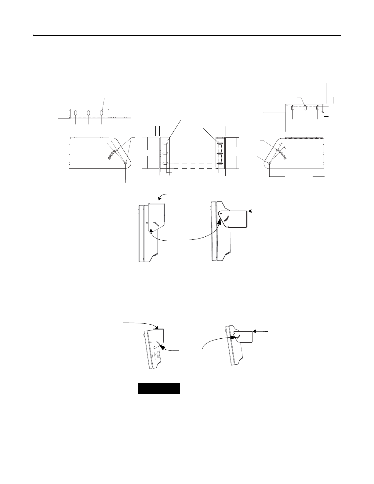
Back-to-back Mount
TIP
Remove only one end cap at a time for each sign.
To mount the signs back-to-back:
1. Attach a mounting bracket on each end of the signs and replace
the end caps.
Follow Steps 1 to 5 of the Wall Mount instructions.
2. However, replace only the bottom three screws for each end cap
and torque the screws to 2.7 Nm (24 lb-in).
Do this for each end of both signs.
TIP
Do NOT fasten the top screws to the end caps. The
top screws are used to fasten the ceiling mounting
brackets to the end caps in the next step.
Do NOT fasten this screw to the end cap.
Fasten these three screws to each end cap.
3. Attach ceiling mounting brackets to all the end caps and torque
the screws to 2.7 Nm (24 lb-in).
See Step 2 of the Ceiling Mount instructions.
Publication 2706-UM016D-EN-P - March 2006
Page 20
1-12 Install InView Marquee Message Display
Ceiling
mounting
bracket
4. Match the signs together back-to-back and connect them
together.
Follow Steps 7 through 10 of the Wall Mount instructions on
page 1-8.
First
sign
Second
sign
Mounting
brackets
First
sign
First
mounting
bracket
Second
sign
Second
mounting
bracket
5. Use chains (not supplied) to hang the signs from the ceiling.
TIP
Use chains capable of supporting 4 times the total
weight of the signs.
Publication 2706-UM016D-EN-P - March 2006
Page 21
Install InView Marquee Message Display 1-13
n
3
Mount the 2706-P72 and 2706-P74 series NEMA 4 and 4x models
Mounted so flanges are hidden behind the sign
2706-P72CNx: 104.8 cm (41.25 in.)
2706-P74CNx: 165.8 cm (65.25 in.)
To mount the sign:
1. Attach the two sign brackets to a wall, ceiling, or other surface.
Be sure to place the brackets so the bracket flanges face
appropriately as shown below. Mount the brackets the following
distance apart (measured from the center of the mounting holes
in each bracket):
Mounted so flanges show on the sides of the sig
2706-P72CNx: 110.5 cm (43.5 in.)
2706-P74CNx: 171.4 cm (67.5 in.)
Wall
or
ceiling
Sign brackets, facing
in behind the sign
IMPORTANT
Do not install the sign directly to drywall or
Sign brackets, facing
out from the sign
plasterboard. The sign must be fastened to a surface
capable of supporting at least four times the weight
of the sign.
0.48 (1.20)
184.15
(7.25 REF)
2. Mount the sign on the sign brackets using the two large hex
bolts supplied.
(0.50 REF)
(0.36 TYP)
End view,
wall-mounted
End view,
ceiling-mounted
Hex bolt
139.70 (5.50)
69.85
(2.75)
19.05
(0.75)
8.74 x 12.70 (0.344 x 0.50)
OBRound Slot (3 Places)
Wall
3. Tilt the sign to select a viewing angle.
4. To hold the sign in place, insert a Phillips screw (supplied)
through one of the small holes on each bracket into the screw
hole in the sign case.
Ceiling
Hex bolt
Publication 2706-UM016D-EN-P - March 2006
Page 22

1-14 Install InView Marquee Message Display
Phillips screw
End view,
wall-mounted
Electrical Connections for 2706-P72 and 2706-P74 Signs
Ceiling
End view,
ceiling-mounted
Wall
TIP
WARNING
Keep a minimum 2.54 cm (1.0 in.) clearance on all
sides of the sign for adequate ventilation.
Hazardous voltage. Contact with high voltage may
cause death or serious injury. Always disconnect
power to sign prior to servicing.
To connect the sign:
1. Open the front of the sign case by turning the quarter-turn
latches to the left with a large screwdriver.
Phillips screw
Front view,
closed
Front view, open
(On the 2706-P72CNx, there are 3 quarter-turn latches; on the
2706-P74CNx there are 4.) Carefully let the front of the case drop
forward.
Quarter-turn latches
Power supply
on an 2706-P74 sign
Serial
connection
Power line
filter
Power
connection
terminal block
Electrical
opening
Serial
device
opening
Publication 2706-UM016D-EN-P - March 2006
Page 23
Right-end
view
Install InView Marquee Message Display 1-15
2. Feed electrical cable through 2.54 cm (1 in.) water-tight conduit,
the outside end of the connector (supplied), the electrical
opening in the sign case, and then through the inside end of the
connector.
3. Screw the inside and outside ends of the connector together
until water-tight.
Rubber gasket
Front view
Conduit
Right-end view
Serial device hole
plug/opening
Sign case,
Electrical opening
inside
Connector nut, with teeth
facing the sign case
4. Strip the electrical wires back 6.35 cm (0.25 in.).
5. Connect the wires by screwing the end of each wire into the
power connection.
Line
(Hot)
BLACK
Power connection
Ground
GREEN
w/
Yel low
GROUND
LINE 1
GROUND
LINE 1
208 - 240 VAC INPUT
LINE 2 OR
NEUTRAL
LINE 2 OR
NEUTRAL
Neutral
(Line 2):
WHITE
6. If the sign is to be used with serial communications, remove one
or both of the hole plugs from the lowest holes on the right end
of the sign case.
Otherwise, proceed to Step 7.
Connector,
outside end
TIP
TB1 can be used for incoming serial connection for
RS-232 or RS-485. The full pinout diagram is shown
below.
Publication 2706-UM016D-EN-P - March 2006
Page 24
1-16 Install InView Marquee Message Display
TB1 Full
Pin Pin Name Pin Pin Name
1. GND 5. RS-485(+)
2. +5V 6. RS-485(-)
3. RS-232 TX 7. NC
4. RS-232 RX 8. SHIELD
7. Connect the incoming serial wires per pinout.
TB1 can be used for incoming RS-485 or RS-232 serial
connection. They cannot be connected at the same time.
RS-485 is recommended to reduce undesirable electrical
interference.
TB1 RS-485
Pin Pin Name Pin Pin Name
1. NC 5. RS-485(+)
2. NC 6. RS-485(-)
3. NC 7. NC
4. NC 8. SHIELD
TB1 RS-232
Pin Pin Name Pin Pin Name
1. GND 5. NC
2. NC 6. NC
3. RS-232 TX 7. NC
4. RS-232 RX 8. NC
TB1
Controller Board
1
2
3
4
5
6
7
8
Publication 2706-UM016D-EN-P - March 2006
Page 25
Install InView Marquee Message Display 1-17
n
P1 can be used for incoming RS-232 only, although it is optional
and not recommended.P1 is intended for RS-232 application
downloads and RS-485 terminating resistor connection.
See publication 2706-IN007 for more information on RS-485
termination.
8. Carefully close the front of the sign case and turn the
quarter-turn latches to the right with a large screwdriver.
Mount the 2706-P92C and 2706-P94C Sign
Mounted so flanges are hidden behind the sign
2706-P92C 103.0 cm (40.55 in.)
2706-P94C: 194.4 cm (76.55 in.)
To mount the sign:
1. Attach the two sign brackets to a wall, ceiling, or other surface.
Be sure to place the brackets so the bracket flanges face
appropriately as shown below. Mount the brackets the following
distance apart (measured from the center of the mounting holes
in each bracket).
Mounted so flanges show on the sides of the sig
2706-P92C: 107.8 cm (43.22 in.)
Sign brackets, facing
in behind the sign
IMPORTANT
Wall
or
ceiling
Do not install the sign directly to drywall or
2706-P94C: 201.2 cm (79.22 in.)
Sign brackets, facing
out from the sign
plasterboard. The sign must be fastened to a surface
capable of supporting at least four times the weight
of the sign.
2. Mount the sign on the sign brackets using the hex bolts
supplied.
3. Insert the bolts into the far single holes first, until the desired
viewing angle is determined.
Publication 2706-UM016D-EN-P - March 2006
Page 26
1-18 Install InView Marquee Message Display
10.16 (.40)
33.78 (1.33)
22.35
(.88)
139.16
(5.40)
44.45
(1.75)
44.45
(1.75)
193.93
(7.635)
8.74 x 17.48
(.344 x .688)
OBROUND
10°
Left Bracket
14.53 (0.572)
Ø 7.14
(.281)
117.60 (4.63)
14.53
(0.572)
3.43 (.135)
33.78
(1.33)
Dimensions are shown in mm (in.) approx.
8.74 x 17.48
(.344 x .688)
OBROUND
10.16(.40)
Ceiling
Hex bolt
for single
hole
38.10 (1.50)
38.10 (1.50)
19.30(.76)
10.16(.40)
14.53
(0.572)
117.60 (4.63)
33.78
(1.33)
0.572 (14.53)
Ø 7.14
(.281)
Ø 7.14
(.281)
8.74 x 17.48
(.344 x .688)
OBROUND
10°
Right Bracket
Wall
44.45
(1.75)
139.16
(5.40)
193.93
(7.635)
44.45
(1.75)
10.16
(.40)
33.78
(1.33)
22.35
(.88)
Ceiling
End view,
wall/ceiling
mounted
4. Tilt the sign to select a viewing angle.
5. To hold the sign in place, insert the remaining bolts into the
desired viewing angle hole on each bracket.
Wall
Desired viewing
angle hole
TIP
Keep a minimum 2.54 cm (1.0 in.) clearance on all
sides of the sign for adequate ventilation.
Publication 2706-UM016D-EN-P - March 2006
Page 27
Install InView Marquee Message Display 1-19
Back-to-back Mount
1. Attach the brackets to the sign in the ceiling mount position with
the hex bolts supplied.
2. Match the signs together back-to-back and connect them
together using a total of six 5/16” bolts and nuts (not supplied).
Attach chains here
First
sign
First
mounting
bracket
Second
sign
Second
mounting
bracket
Electrical Connections for 2706-P92C and 2706-P94C Signs
3. Attach chains (not supplied) to the top mounting holes of the
bracket to hang the signs from the ceiling.
TIP
WARNING
Use chains capable of supporting 4 times the total
weight of the signs.
HAZARDOUS VOLTAGE
• Contact with high voltage may cause death or
serious injury. Always disconnect power to sign
prior to servicing.
• Maintain Separation of circuits. Route the
incoming power directly to the power connection
terminal block.
• Do not run the power wiring over the logic board
or optional Communication board.
Open the front of the sign case by turning the half-turn latches
to the left with a large screwdriver. On the 2706-P92C, there are
3 half-turn latches; on the 2706-P94C there are 5. Carefully let
the front of the case drop forward.
Publication 2706-UM016D-EN-P - March 2006
Page 28
1-20 Install InView Marquee Message Display
Front view,
closed
Front view, open
Half-turn latches on an 2706-P94C sign
Electrical
opening
Power connection
terminal block
Communication
opening
4. Feed electrical cable through 12.7 mm (0.5 in.) water-tight
conduit, the outside end of the connector (supplied), the
electrical opening in the sign case, and then through the inside
end of the connector.
5. Screw the inside and outside ends of the connector together
until water-tight.
TIP
Use either of the two holes nearest the power
connection terminal block.
Rubber gasket
Front view
Sign case,
inside
Connector nut, with teeth
facing the sign case
6. Strip the electrical wires back 6.35 mm (0.25 in.).
Conduit
Connector,
outside end
Publication 2706-UM016D-EN-P - March 2006
Page 29
Install InView Marquee Message Display 1-21
7. Insert the wires into the appropriate terminal connection and
tighten the screw to 0.79 Nm (7 lb-in).
The terminal block is UL rated for wire ranges of 14 to 8 AWG.
Ground
Line
(Hot) BLACK
GREEN w/ Yellow
LINE 2 OR
NEUTRAL
GROUND
LINE 1
Neutral
(Line 2): WHITE
Power connection
GROUND
LINE 1
208 - 240 VAC INPUT
LINE 2 OR
NEUTRAL
8. Remove the necessary hole plugs before connecting the
communications cables.
9. Connect the incoming communication wires per the tables
below.
ATTENTION
Use shielded Ethernet cable. Shielded Ethernet
cable is required to maintain noise immunity.
The 2706-PCable1 is used for downloading
messages only and must be removed after
downloading is complete.
TB1 is used for P9x pass-through. TB2 is used for supplying
power to the optional InView Legacy Communication board kit.
Communication
Openings
Ethernet
TB1
TB2
TB1 RS-485
Pin Pin Name Pin Pin Name
1. GND 4. CH A
2. SHLD 5. CH B
3. COMM 6. TERM
Publication 2706-UM016D-EN-P - March 2006
RJ-12
TB3
Page 30

1-22 Install InView Marquee Message Display
TB2 - Aux +5V
Pin Pin Name Pin Pin Name
1. +5V 2. GND
TB3 - RS-232
Pin Pin Name Pin Pin Name
1. TXD 4. CTS
2. RXD 5. GND
3. RTS 6. EGND
8
1
RJ12
12 345 6
+5V NC TX RX NC GND
Ethernet (RJ-45)
(1)
Pin Pin Name Pin Pin Name
1. TD+ 5. NC
2. TD- 6. RD-
3. RD+ 7. NC
4. NC 8. NC
(1)
Use shielded Ethernet cable to maintain noise immunity.
Download Port (RJ-12)
(1)
Pin Pin Name Pin Pin Name
1. Aux +5V 4. RX
2. NC 5. NC
3. TX 6. GND
(1)
The 2706-PCable1 is used for downloading messages only and must be removed after downloading is
complete.
10. Carefully close the front of the sign case and turn the half-turn
latches to the right with a large screwdriver.
Publication 2706-UM016D-EN-P - March 2006
Page 31

Install InView Marquee Message Display 1-23
Mount the 2706-P22R Display
The following provides panel cutout dimensions and overall
dimensions for the InView P22R panel mount display.
The InView P22R mounts in a custom panel or enclosure. When it is
properly installed, the faceplate provides a NEMA Type 12, 13, and
4X(indoor) rating.
To mount the display:
1. Cut and drill the appropriate mounting holes in the enclosure or
panel.
Refer to Panel Cutout Dimensions for 2706-P22R Display on
page 1-23
2. Remove the six mounting nuts and washers from the hardware
bag provided with the display.
3. Position the InView Display in the panel or enclosure mounting
hole.
4. Install washers and nuts and alternately tighten the nuts to a
torque of 0.904 Nm (8 lb-in).
TIP
InView P22R mounting and panel cutout are
identical to DL40 Plus, DL40, DL20 and DL10 two
line displays.
Panel Cutout Dimensions for 2706-P22R Display
All dimensions are in millimeters (inches)
4.8 (0.19)
Cutout
173.0 (6.81)
Cutout
88.9
(3.50)
4.8 (0.19)
176.1 (6.94)
Cutout 345.9 (13.62)
2706-P22R Display
352.3 (13.87)
98.4
(3.88)
6.4 (0.25)
Diameter
Hole
6 places
Publication 2706-UM016D-EN-P - March 2006
Page 32

1-24 Install InView Marquee Message Display
Dimensions for 2706-P22R Display
111.3
(4.38)
337.3
(13.29)
365.0 (14.357)
All dimensions are in millimeters (inches)
Electrical Connections for 2706-P22R Display
83.8
(3.30)
61.7
(2.43)
The InView display requires 18 to 30V dc, 0.5 A at 18V dc.
ATTENTION
Before making power connections, make sure that
the power is turned off. Improper wiring of the
power connections may result in personal injury or
damage to the InView display. Make sure the area
around the panel cutout is clear. Make sure metal
cuttings or debris did not enter any components
that may have been installed in the panel.
InView P22R Power Connection
68.8
(2.71) with fuse
Publication 2706-UM016D-EN-P - March 2006
IMPORTANT
TIP
To satisfy all agency requirements and ensure
proper operation, power this product using a
24V dc, class 2 SELV power supply.
Use a small screwdriver to remove the terminal
block’s header to ease product wiring.
Page 33

Communication Connections for 2706-P22R Display
Install InView Marquee Message Display 1-25
RJ12
RS-485
1 - E-GND
2 - SHLD
3 - COMM
4 - CH A
5 - CH B
6 - TERM
12345 6
+5V NC TX RX NC GND
RS-232
12345
67 8 9
RJ11 Connections
Pin Pin Name Pin Pin Name
1. +5 V 4. RX
2. NC 5. NC
3. TX 6. GND
RS-485 Connections
Pin Pin Name Pin Pin Name
1. E-GND 4. CH A
2. SHLD 5. CH B
3. COMM 6. TERM
RS-232 Connection
Pin Pin Name Pin Pin Name
1. NC 6. NC
2. RX 7. RTS
3. TX 8. CTS
4. NC 9. NC
5. GND
Publication 2706-UM016D-EN-P - March 2006
Page 34

1-26 Install InView Marquee Message Display
DIP Switch Settings for 2706-P22R Display
ATTENTION
Switch Settings
11
22
34
48
516
632
764
8 128
Dip Switches
Dip Switch Label
LSB
Serial
Address
MSB
Diagnostics
Not Used
Disconnect power from the InView display before
setting any switch. Switch settings are scanned only
on power-up.
Dip Switch Settings
Switch Switch Setting Switch Switch Setting
1. 1 (LSB) 6. 32
2. 2 7. 64
3. 4 8. 128 (MSB)
4. 8 9. Diagnostics
5. 16 10. Not Used
Publication 2706-UM016D-EN-P - March 2006
Page 35

Install InView Marquee Message Display 1-27
Download a Message Application
InView message applications are created using the InView messaging
software (2706-PSW1). After creating the Message Application, you
need to download it into your InView display memory.
InView applications can be downloaded using:
• Point-to-point serial communications (RS-232) from the
communication port on a personal computer.
• Multi-drop RS-485 serial communications. Utilizing a
1761-NET-AIC to convert RS-232 to RS-485 from a personal
computer allows you to download to multiple displays over
RS-485.
• 2706-PCABLE1 which connects from your PC, running InView
messaging software, to the phone jack type connector on your
InView display. In larger InView models, this phone jack may be
behind the power supply cover.
• EtherNet TCP/IP networking. With the InView 2706-PENET1
EtherNet TCP/IP communication module you can download
message applications from a personal computer over Ethernet.
For more information on this communications option, see
publication 2706-IN008.
RS-232 to RS-485 Networking
• InView communication modules. The communication modules
allow the displays to communicate on the core Allen-Bradley
networks.
With the use of an Allen-Bradley 1761-NET-AIC, you can convert
RS-232 to RS-485 and daisy chain InView Displays up to 1219 m
(4000 ft).
1761-NET-AIC (AIC+)
Publication 2706-UM016D-EN-P - March 2006
Page 36

1-28 Install InView Marquee Message Display
RS-485 Echo
The RS-485 echo feature addresses the issue of increased network
traffic often caused by multiple node addresses and high consumption
of communication bandwidth. The display’s design enables users to
daisy-chain numerous InView displays off an InView P9x via the
RS-485 communication network.
2706-P9x - Master InView
RS-485 Network
In order to set the 2706-P92C display or the 2706-P94C display as a
Master, the echo dip switch must be enabled.
See Dip Switch Information for the 2706-P9x in Chapter 2.
TIP
Only one 2706-P9x InView display can be set as the
master per RS-485 network.
When the echo feature is enabled, all incoming packets, whether it is
over the RS-232 port, RJ12 download port, or the RJ45 10/100 base-T
Ethernet port, are echoed out the RS-485 port.
An InView master display inspects the incoming packets and
determine if the packet is addressed to itself and take the appropriate
action. The master shall ignore all packets that are not addressed to
itself. The only exception is for a packet with an address of 255. This
is the broadcast address and must be accepted by all displays on the
network.
TIP
When the 2706-P9x display, echo feature is enabled,
the RS-485 port of the 2706-P9x display, does not
accept incoming packets. The port is exclusively
used to echo out data.
Publication 2706-UM016D-EN-P - March 2006
Page 37

Install InView Marquee Message Display 1-29
Global Addressing
The 2706-P92C and 2706-P94C displays can both set their serial
address to 255, which is the global (broadcast) address. A display with
the serial address of 255, accepts all message packets regardless of the
address actually given in the packet. This allows the user to route all
messages to the 2706-P9x InView display.
See Dip Switch Information for the 2706-P9x in Chapter 2, for serial
address configuration.
Ground and Terminate the RS-485 Network
TIP
Only one device at either end of the link must have earth ground and
shield jumpered together. This provides an earth ground connection
for the shield of this communication cable. If the connection is made
at an AIC or AIC+, jumper terminals 1 and 2. If the connection is made
at a 2706-P4x or 2706-P7x display, jumper terminals 1 and 8. If the
connection is made at a 2706-P22 display, jumper terminals 1 and 2.
Both ends of the network must be terminated. There is an impedance
of 120 ohms built into each AIC and AIC+ as required by the RS-485
specification. Jumper terminals 5 and 6 of the AIC or AIC+ for
end-of-line termination.
End-of-Line Termination for AIC and AIC+
A global address of 255 can only be set by hardware
and cannot be set using software.
Jumper
Belden #3106A or #9842 Cable
1219 m (4000 ft) Maximum
Jumper
Publication 2706-UM016D-EN-P - March 2006
Page 38

1-30 Install InView Marquee Message Display
RJ11 RJ11
Network Wiring
6
Term
A
B
COM
SHLD
GND
1
1761-NET-AIC
8
1
8
SHLD
AUX
RS485(-)
RS485(+)
RxD
TxD
+5V
GND
1
2706-P44C2706-P74C
6
Term
B(-)
A(+)
COM
SHLD
E-GND
1
2706-P9x
6
Term
B(-)
A(+)
COM
SHLD
E-GND
1
2706-P22R
End-Of-Line Display
TIP
End-of-line InView display should have terminating
resistor in RJ11 (P1). If a 2706-P22R display is the
end-of-line display, jumper terminals 5 and 6. There
is a built in impedance of 120 ohms similar to that of
the AIC and AIC+.
Publication 2706-UM016D-EN-P - March 2006
Page 39

Chapter
2
InView System Connectivity
This chapter demonstrates how the InView display connects to control
networks. In the following chapters we show controller configuration
and sample ladder for serial ASCII networks. This chapter also
discusses how to set-up the display attributes, communications and
create messages.
Serial ASCII Communications
Features
Refer to Chapter 3 for more information on Serial ASCII
communications from Channel Zero of an Allen-Bradley controller.
Serial Connections
Point-to-Point
CH 0
Multi-Drop
CH 0
The features are separated into sections for the 2706-P4x and
2706-P7x displays and the 2706-P22R displays.
RS-232
RS-232
AIC+ Converter
RS-485
InView Display
InView Display
InView Display
2706-P42, 2706-P43, 2706-P44, 2706-P72, and 2706-P74 Displays
These displays operate at 100 to 240V ac. They have an eight position
terminal block that contains an auxiliary +5V dc, RS-232 signals, and
RS-485 signals. There is also an RJ-12 port that is in parallel with the
RS-232 signals from the terminal block. The RJ-12 port is used
primarily for downloading messages to the display via the
2706-PCABLE1 download cable.
1 Publication 2706-UM016D-EN-P - March 2006
Page 40

2-2 InView System Connectivity
TB1 Connections
8
7
6
5
4
3
2
1
TB1
Incoming serial
wires
These displays have a single channel UART and therefore can only
have one of the three communication options connected at a time.
• RJ-12
• RS-232 terminal block connections
• RS-485 terminal block connections
TB1 - Full
Pin Pin Name Pin Pin Name
1. GND 5. GND RS-485(+)
2. +5V 5. +5V RS-485(-)
3. RS-232 TX 6. RS-232 TX NC
4. RS-232 RX 7. RS-232 RX SHIELD
2706-P22 Display
This display operates at 18 to 30V dc. It has three communication
ports. These are the RJ-12, DB-9, and a six position terminal block
ports. The RJ-12 port is used primarily for downloading messages to
the display via the 2706-PCABLE1 download cable. The DB-9 port is
used for RS-232 communications and the signals are in parallel with
the RJ-12 port. Therefore, only one of the ports may be connected at a
time. The six position terminal block is used for RS-485
communications. The 2706-P22R display has a two-channel UART.
This means that one of the RS-232 ports and the RS-485 port can be
connected at the same time.
Publication 2706-UM016D-EN-P - March 2006
2706-P22R Display Communication Connections
RJ11 Pin-out
1 - +5V
2 - NC
3 - TX
4 - RX
5 - NC
6 - GND
RJ12
12 345 6
+5V NC TX RX NC GND
RS-232
12345
67 8 9
RS-485
1 - E-GND
2 - SHLD
3 - COMM
RS-232 Pin-out
1 - NC
2 - RX
3 - TX
4 - NC
5 - GND
6 - NC
7 - RTS
8 - CTS
9 - NC
4 - CH A
5 - CH B
6 - TERM
RS-485 Pin-out
1 - E-GND
2 - SHLD
3 - COMM
4 - CH A
5 - CH B
6 - TERM
Page 41

InView System Connectivity 2-3
RJ11 Connections
Pin Pin Name Pin Pin Name
1. +5 V 4. RX
2. NC 5. NC
3. TX 6. GND
RS-485 Connections
Pin Pin Name Pin Pin Name
1. E-GND 4. CH A
2. SHLD 5. CH B
3. COMM 6. TERM
RS-232 Connection
Pin Pin Name Pin Pin Name
1. NC 6. NC
2. RX 7. RTS
3. TX 8. CTS
4. NC 9. NC
5. GND
The 2706-P22R display has a ten-position dip switch. The first eight
positions are used to set the address of the display. Position nine is
used to put the display in diagnostic mode. Position ten is a spare.
The dip switch is read only on power-up.
The diagnostic mode causes the display of LED patterns to visually
indicate if any pixels are not turning on. It also performs a memory
check.
IMPORTANT
After one complete LED scan is done, a RAM check
is performed and the display’s memory is cleared. To
ensure that the display’s memory is not cleared, turn
off power to the display after the LED block test is
performed. Make sure that the download or message
file has been saved before diagnostic test is allowed
to run completely through.
Publication 2706-UM016D-EN-P - March 2006
Page 42

2-4 InView System Connectivity
2706-P22R Display Dip Switch Settings
Switch Settings
11
22
34
48
516
632
764
8 128
Dip Switches
Dip Switch Label
LSB
Serial
Address
MSB
Diagnostics
Not Used
Dip Switch Settings
Switch Switch Setting Switch Switch Setting
1. 1 (LSB) 6. 32
2. 2 7. 64
3. 4 8. 128 (MSB)
4. 8 9. Diagnostics
5. 16 10. Not Used
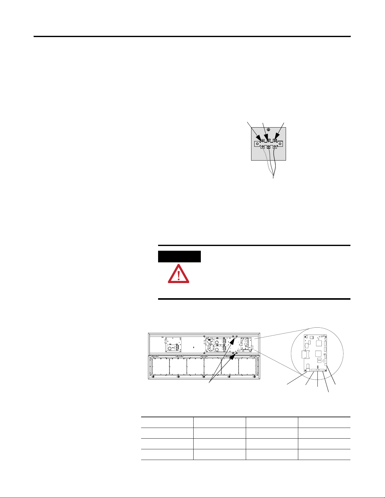
Dip Switch Information for the 2706-P9x
There are two dip switches located on the controller board, Switch 1
and Switch 2.
2706-P9x Dip Switch
Switch 1
Switch 2
Switch 1
Switch 1 is used to configure the display’s RS485 echo enable,
communication rate settings, and display size.
Publication 2706-UM016D-EN-P - March 2006
Page 43

InView System Connectivity 2-5
Position 1 enables or disables the echo function.
When you enable the RS485 echo function, this allows any packets
that come in on COM 0 (download, RJ-12 port), COM 1 (RS-232, TB3
port), and the Ethernet TCP/IP port to be sent out the RS485 port. This
allows Ethernet TCP/IP and other communication protocols to be
converted to RS485 by a single 2706-P92 or 2706-P94 and then sent
out to multiple RS485 networked displays.
TIP
Only enable the echo function on one
2706-P9x display.
Positions 3 and 4 set the communication rate.
Refer to page 2-6 for default positions.
If both switches are off, the communication rate can be set via the
InView messaging software. The dip switches take priority over the
software setting. If the communication rate is set to 19200 using the
software (positions 3 and 4 set to off) and then set to 9600 using
Switch 1 (position 3 on and 4 off), the communication rate is 9600.
Also, once positions 3 and 4 are used to set the communication rate
and then they are switched off, the communication rate setting
remains until it is changed by software or a different dip switch
setting.
Position 5 is used to set the display size. This is set by the factory.
Position 6 is used to turn on diagnostics.
Position 7 disables download message.
Switch 2
Switch 2 is used to set the serial address of the display. Position 1 is
the LSB of the address and position 8 is the MSB of the address.
If position 1 is on and all other positions are off, the display address is
1.
If position 8 is on and all other positions are off, the display address is
128.
If all positions are set to off, the serial address is set using the InView
messaging software.
Publication 2706-UM016D-EN-P - March 2006
Page 44

2-6 InView System Connectivity
The dip switch setting takes priority over the software setting. If the
serial address is set to 2 using the software (all the dip switches set to
off) and then Switch 2 is used to set the serial address to 3 (position 1
and 2 set to on and the remaining positions set to off), the serial
address is 3. Also, once Switch 2 is used to set the serial address and
then all switch positions are set to off, the serial address setting
remains until it is changed by software or the dip switch is set.
.2706-P9x Dip Switch Settings
Baud Rate
3 4
OFF OFF = Software
Default
ON OFF = 9600
OFF ON = 19200
ON ON = 38400
RS485
Echo
Not
Used
Size
ON = P92C
OFF = P94C
Not
Used
ON =
Disable
Download
Message
ON =
Diagnostics
LSB
Display Address
Switch12345678
Value1248163264128
MSB
Additional Information for 2706-P9x Displays
For additional information on communication port wiring and display
configuration, refer to the InView Marquee Message Display User
Manual, publication 2706-UM016.
This product contains a Lithium battery. See publication 2711P-IN009
for information regarding battery replacement and disposal.
Communications Board Kits
Publication 2706-UM016D-EN-P - March 2006
There are optional Communications Board Kits available for the
2706-P9 series displays. There are a total of six board kits:
• Remote I/O (2706-PRIOK)
• DH+ (2706-PDHPK)
• DH-485 (2706-PDH485K)
• ControlNet (2706-PCNETK)
• DeviceNet (2706-PDNETK)
• EtherNet/IP (2706-PENETK).
Page 45

InView System Connectivity 2-7
The Communications Board Kits convert the six protocols to RS-232.
The board kit mounts on the four PEM spacers that are attached to the
internal mounting plate.
See publication 2706-IN015 for more information on how to install the
board kits.
Spacer Location
PEM Spacers
Compact Flash Card
This product uses a Type I Compact Flash Card for message file
storage.
Refer to publication 2706-IN017 for information on replacement and
installation of the Compact Flash Card.
Multiple Communication Rate Support
The 2706-P92C and 2706-P94C displays allow the user to select serial
communication rates of 9600, 19200,or 38400 bps. The communication
rates are both hardware (dip switches) and software selectable.
TIP
The communication rate of the display is set using the InView
messaging software, provided the communication rate dip switches
are all off.
For selecting the communication rate using the dip
switches, see the section entitled Dip Switch Settings
Publication 2706-UM016D-EN-P - March 2006
Page 46

2-8 InView System Connectivity
To set the communication rate using the messaging software:
1. Highlight the 2706-P9x display you wish to set the
communication rate.
2. Select Set Display Baud Rate under the Tools menu.
Publication 2706-UM016D-EN-P - March 2006
3. Choose the communication rate you wish to set the display at
and click on the Set button.
TIP
There is no confirmation that the command was sent.
The display must be power cycled to view the new
communication rate settings.
Page 47

InView System Connectivity 2-9
Isolated Communication Ports
The isolated communication ports consist of RS-232, RS485, 10/100
Ethernet port and a RS-232 download port. This allows the 2706-P92C
and 2706-P94C displays to support multiple networks simultaneously.
This allows programmers to change the messages or tie into an
information database, while control operators can continue delivering
alarms and messages to the plant floor.
Isolated Communication Ports
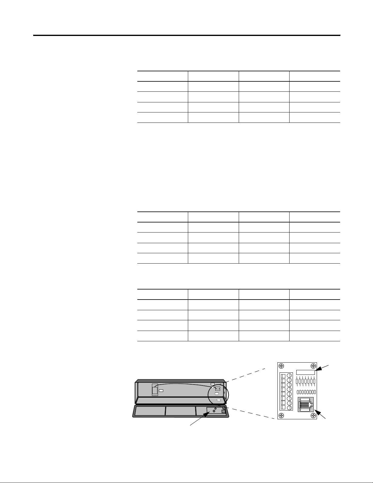
Flash Programmable Firmware
The programmable Compact Flash card is located inside the 2706-P9x
display on the controller board as shown below.
TIP
Compact Flash Card
The Compact Flash card must be at least 32 MB,
anything less is not supported.
Publication 2706-UM016D-EN-P - March 2006
Page 48

2-10 InView System Connectivity
Power-up Messages
After the power cable and the download cable (attaches to the RJ-12
port) have been attached per the installation document, apply power
to the display.
TIP
If a display is connected to Ethernet via TCP/IP by
using a 2706-PENET1 module or a 2706-P9x display
is connected to Ethernet via TCP/IP, the display
configuration and message download can be done
over Ethernet. For more information on this
communication option, see publication 2706-IN008.
2706-P42, 2706-P43, 2706-P44, 2706-P72, 2706-P74, 2706-P92, and
2706-P94 Displays
After power is applied to the display the following messages are
displayed.
• firmware number and revision
• memory size and partition
• memory checksum message
• date and time
• address of the display; and background message, if one was
created
2706-P22: Display
After power is applied to the display the catalog number, firmware
revision, and address is displayed on one screen. Then the
background message is displayed.
See the help file for more details on the following topics.
Publication 2706-UM016D-EN-P - March 2006
Page 49

InView System Connectivity 2-11
Display Setup
To set up your display:
1. Start the InView messaging software.
2. Create a project.
The software prompts for a project file name, a project name,
and description. Once this is done, the project name and
description appears in the Displays box.
3. The software then prompts for a display name, display
description, display type, and the number of that particular
display that is used in the system (1 to 100 of the same display
type).
4. Select one for the number of displays (once displays have been
assigned a unique address, more than one can be added at
once).
5. Select Next.
6. The software then prompts for the address of the display,
heartbeat, TCP/IP settings (if applicable), and the serial com port
settings.
Set the IP Address
Use the default settings of 9600, None, 8, and 1.
7. Select Next.
8. When the software prompts for a message file association, check
Create a New Message File.
9. Enter the message file name and select Finish.
The message editor window is displayed.
For the 2706-P22, 2706-P4x, and 2706-P7x terminals, separate
communication modules are needed to place the display on the
network. The 2706-P9x displays have Ethernet TCP/IP built in. To add
any other network protocol to the 2706-P9x, a separate
communication module is needed.
The Ethernet TCP/IP configuration utility is installed as part of the
Inview messaging software package. When first opening the InView
messaging software, you are asked to create a display and a message
file. After the display is created you can configure the IP address of
the 2706-PENET1 module.
Publication 2706-UM016D-EN-P - March 2006
Page 50

2-12 InView System Connectivity
The 2706-PENET1 module is the communication interface for Ethernet
TCP/IP. This module is used with the 2706-P22, 2706-P4x, and
2706-P7x displays. The 2706-P9x displays have this protocol built in.
Note that the 2706-PENET1 is Ethernet TCP/IP or Office type Ethernet
and is not Ethernet I/P, which is Ethernet Industrial Protocol available
on Rockwell Automation logic controllers.
To set the IP address:
1. Select the display you created, which use a the Ethernet module.
2. Right click on the display and select Edit Display.
TIP
Double-clicking on the display takes you to the
same window.
3. When the Edit Display window appears, go to the
Communications tab.
This is where the configuration utility is located.
Publication 2706-UM016D-EN-P - March 2006
Page 51

InView System Connectivity 2-13
Under the section with the heading TCP/IP settings is the
Configure Communications button.
4. By clicking this button you are taken to the Ethernet TCP/IP
Communications window.
This is where the IP address will be set.
5. At the top of the window labeled IP Address, enter the desired
IP address.
Publication 2706-UM016D-EN-P - March 2006
Page 52

2-14 InView System Connectivity
6. Enter 3001 for the Port if using a 2706-PENET1 module.
7. Enter the MAC Address of the module under the heading Assign
IP Address.
The MAC Address is found on the module itself.
TIP
The 2706-P9x display does not use MAC Address. IP
Address changes must be done serially.
8. Click the Setup button located in the section titled Assign IP
Address once the desired IP Address, Port, and MAC Address
have been entered.
If the IP Address is already in use, an error message window
appears.
TIP
If the Invalid IP Address window appears, click
OK, choose a different desired IP Address, and
click the Setup button again. Once a valid IP
Address is entered, the following window should
appear saying it is ready to assign an IP address.
Publication 2706-UM016D-EN-P - March 2006
As the message instructs, you need to either turn the display on
or power cycle the display if it is already turned on. Upon
successfully assigning an IP Address the following window
appears.
Page 53

InView System Connectivity 2-15
Gateway Address and Subnet Mask Setup
Set up the Gateway address and Subnet Mask if needed based on your
Ethernet Network configuration. Default values typically are for
Subnet Mask, 255.255.255.0 and as a default the Gateway address is
left blank.
Subnet Mask is a parameter that interprets IP addresses when the
network is divided into multiple networks. The IP address is formatted
as four sets of decimal numbers with periods between them
(255.255.255.1). The range of values for the first set of decimal
numbers is 1 to 255. The range of values for the last three sets of
decimal numbers is 0 to 255. The value 0.0.0.0 is not a valid subnet
mask.
Gateway Address is a unique address of the Gateway connecting two
individual IP networks into a system of networks. When a node needs
to communicate with a node on another network, the Gateway
transfers the data between the two networks. The IP address is
formatted as four sets of decimal numbers (from 1 to 255) with
periods between them (130.0.0.1). The first field cannot be 0 if any
other fields contain a 0.
Once the desired Gateway Address and Subnet Mask have been
entered, click on the Setup button located just below where the
Subnet Mask was entered. If for some reason, the settings are not
received by the 2706-PENET1 module, the following error message
will appear.
However, upon successfully setting up the Gateway Address and
Subnet Mask, the following message appears telling you to cycle
power to the module.
Publication 2706-UM016D-EN-P - March 2006
Page 54

2-16 InView System Connectivity
After the IP Address, Gateway Address and Subnet Mask have all been
established, click the OK button on the bottom of the Ethernet TCP/IP
Communications window. This allows the settings to be saved and
configuration is now complete.
Once the settings have been saved, they can now be viewed by
clicking on the Advanced button located in the section titled TCP/IP
settings on the Edit Display window.
Create the Message File
A background message of Rockwell Automation is automatically
created. This is also indicated by the letter B in the message list below
the message creation box. Message number 1 is highlighted and ready
for creation. Create a message by typing in the message box.
Attributes for the messages can be changed or added using the pull
down menus located above the message creation box or from the
toolbar. Once message number 1 has been created, select the down
arrow or type 2 in the box and select the Goto button. This allows
message number 2 to be created.
There is a size displayed in the lower right of the window. This is the
size of the message that is being created. This number starts from 11
and increases to a maximum number that is determined by setting the
partition size in software. This is based on a total of 200,000 bytes.
The smaller the partition size the more messages are available. The
limits are 450 bytes per message, 444 messages minimum to 50 bytes
per message, 4000 messages maximum. To change the partition size,
select File then Partition.
See the following sections for more information regarding the
message attributes.
Publication 2706-UM016D-EN-P - March 2006
Message File Additional Information
Task Page
Attach a Note to a Message 2-17
Text Color 2-17
Date, Time and Variables 2-17
Category 2-18
Message Priorities 2-18
Page 55

InView System Connectivity 2-17
Message File Additional Information
Ta sk P ag e
Pause 2-19
Message Header 2-19
Preview Messages 2-19
Set the Display Address 2-19
Download Messages 2-20
Clear Memory/Message Queue 2-22
Attach a Note to a Message
Select a message from the message list. Select Tools and Edit Note.
Then a Message X Note window appears. The X is the message
number for the message that a note is being created for. These
message notes can only be viewed with the InView messaging
software and are not downloaded to the display.
Text Color
There are three color options if a display is classified as color. They
are red, green, or yellow. The color of the message is the color that is
selected. The color of individual text within the message is changed
by inserting a color before the text. The text after the color insert stays
that color until a new color insert is performed.
Date, Time and Variables
The date, time and variables are also inserted into a message. These
are found under the Edit menu then Insert or via the toolbar buttons.
If inserting the date, a pop-up window appears and shows various
formats and a pre-viewer that displays the data for the selected format.
If inserting a variable, a pop-up window appears that allows the
selection of the variable number and whether the variable is numeric
or alpha numeric. The maximum number of variables per message file
is 100 (00 to 99). The numeric variable ranges from 32,767 to -32,768
decimal. It also allows the selection of the type of padding and a
check box for a sign (+/-). An alpha numeric variable is ASCII text
except for the “. It also varies in length from 1 to 128 characters. There
is a pre-viewer that displays the options selected. The format for the
time is either standard or military. The selection for this is found in the
Publication 2706-UM016D-EN-P - March 2006
Page 56

2-18 InView System Connectivity
InView configuration window (the project window) under Tools and
Set Display Date and Time. Note that the time format is set for each
display individually by address. The default format is standard. The
data and time is also set here.
Category
The Category option is used to assign categories to messages. This
helps in organizing messages for certain operations and when
performing a find.
Message Priorities
The Priority option is used to give messages a priority of low,
medium, and high. As an example, a normal operating water
temperature reading of a generator is a low priority message. A
pre-alarm message of high water temperature is a medium priority
message. An alarm message of high water temperature shutdown is a
high priority message.
In our example, the water temperature is part of the generator signals
that are constantly being monitored and displayed as low priority
signals in the message queue (the message queue can hold up to 64
messages). When the water temperature rises above a pre-alarm
threshold, the medium priority high water temperature message is
added to the message queue. When this happens, only medium
priority messages are displayed. If other medium priority messages
were added to the queue, they are also displayed until a high priority
message is added to the queue. When the water temperature rises
above an alarm threshold, the high priority high water temperature
shutdown messages are displayed.
In order to view the low priority messages, the medium and high
priority messages need to be removed from the message queue.
See InView Protocol, Chapter 4, for information on how to add or
remove messages from the message queue.
Publication 2706-UM016D-EN-P - March 2006
Page 57

InView System Connectivity 2-19
Pause
The Pause option determines how long a message is displayed when
a message queue (two or more messages are being displayed due to a
download and display or messages were added to a message queue)
is running.
See InView Protocol, Chapter 4, for information on how to messages
to the message queue.
Message Header
A header is added to a message by clicking the H button. Once this
button is clicked, the button appears depressed and any text in the
message creation box shifts from the top line to the bottom line.
Preview Messages
Messages are previewed before downloading. This option is found
under the View menu then Preview Mode or by clicking the
magnifying glass button.
After the message file is created, exit the message editor. The message
file is automatically saved as it is created. If an edit is needed to a
message file, double click a message in the Message File Details list in
the project window. This brings up the message editor window.
Set the Display Address
All displays except for the 2706-P9x and 2706-P22R displays must
have their addresses set through software. The factory default address
setting for all InView displays is 01. This is the old address when
setting up the display for the first time. To set the display address
using the software, select Tools and Set Display Address. The display
communication settings (com port and communication rate, or TCP/IP
settings) should have been set when the display was added to the
project.
The 2706-P22R display address is set either in the software using
InView messaging or by using the dip switch. The first eight positions
of the dip switch are used for setting the display address. If all the dip
switches are off, the address is set in the software. If any of the first
Publication 2706-UM016D-EN-P - March 2006
Page 58

2-20 InView System Connectivity
eight dip switch positions are on, this is the display address and the
software setting is overwritten. Once an address is selected by the dip
switches, it is retained until it is overwritten by the software (only
done when all switches are off) or the dip switches are changed.
Once a unique address has been set, future display properties and
message communications are done to networked signs via RS-485.
Message downloads, communications, and display properties are
done to networked signs via Ethernet TCP/IP.
See the 2706-PENET1 pdf in the Product Literature folder on the
InView Messaging Software CD for more information on using this
communication option.
Download Messages
Once the message file has been created, there are several download
options.
• Download the entire file - Download Message File and
Broadcast Download
• Download selected messages - Download Message
• Download and display selected messages - Trigger Message and
Broadcast Trigger Message
• Message broadcast – Broadcast Download Message
A pop-up window appears when any of these options, except for
broadcast, are selected. This window allows the selection of which
displays to download to.
TIP
Assign the address and communication settings for
each display before any messages are downloaded.
These options are found under Message File and
Message.
Download Message File and Broadcast Download
Broadcast Download downloads the entire file to all displays on the
network. Download Message File downloads the entire file to the
display specified. Download Message File and Broadcast Download
overwrite the old messages starting at message number one to where
the new messages end. If the old message file has more messages
than the new message file, the old messages above the new message
Publication 2706-UM016D-EN-P - March 2006
Page 59

InView System Connectivity 2-21
file end remains. For example, the old message file had messages 1
through 10 and a background message. The new message file has
messages 1 through 2 and a background message. After the new
message file is downloaded, the new message file contains new
messages 1 through 2, a new background message, and old messages
3 through 10. If the new message file does not contain a background
message, the background message is blank. If just the new message
file is to be retained in memory, a clear memory operation should be
performed before downloading a new message file. This erases the
entire memory of the display.A message trigger or addition to the
queue is required in order to view the downloaded messages.
See InView Protocol, Chapter 4, for information on how to trigger a
message or add it to the queue.
Download Message
Download Message downloads only those messages selected from the
message list. To select messages, highlight them from the Message File
Details box in the InView messaging software (project) window. Once
they have been downloaded, the display behaves the same as if the
entire message file were downloaded. A message trigger or addition to
the queue is required in order to view the downloaded messages.
See InView Protocol, Chapter 4, for information on how to trigger a
message or add it to the queue.
Trigger Message and Broadcast Trigger Message
Trigger Message and Broadcast Trigger Message allows up to 64
messages selected from the message list to be displayed after
download. This is the message queue. Each message is displayed for
the amount of the pause time that is set when the message is created.
TIP
If new messages are downloaded using this option, a clear message
queue command is done before the messages are downloaded. The
old messages are erased and replaced with the new ones. Broadcast
Trigger Message downloads the selected messages to all displays on
the network.
Only messages of the highest priority are displayed.
When using this option, ensure that all the messages
have the same priority.
Publication 2706-UM016D-EN-P - March 2006
Page 60

2-22 InView System Connectivity
Clear Memory/Message Queue
These options are found under Tools then Clear Display Memory and
Clear Display Message Queue. The clear memory option erases the
entire memory of the display. Memory Cleared is displayed and then
the display goes through a reset cycle. The clear message queue
option just erases the queue, not the display memory. If there is a
background message, it is displayed after a clear message queue
command has been issued.
Publication 2706-UM016D-EN-P - March 2006
Page 61

Serial ASCII Communications
Chapter
3
Use a PLC5 out Channel Zero
To use a PLC5 out Channel Zero on a display:
1. Create a new application.
2. Set up the channel configuration.
3. Create a file type String (ST).
This is where the user inserts the ASCII/Hex commands.
4. Set up the ladder logic.
B3:0
0
1
1 Publication 2706-UM016D-EN-P - March 2006
0
ASCII Write
Channel 0
Source
Control R6:0
String Length 0<
Characters Sent 0<
AWT
ST9:0
EN
DN
ER
(End)
Page 62

3-2 Serial ASCII Communications
Use an SLC 5/03, 5/04, or 5/05 out Channel Zero
B3:0
0
1
0
The SLC processor is set up very similar to the PLC processor. The SLC
processor uses the same ladder logic as the PLC processor shown
below.
To use an SLC processor out Channel Zero on a display:
1. Create the new application and then set up the channel
configuration as shown.
AWT
ASCII Write
Channel 0
Source
Control R6:0
String Length 0<
Characters Sent 0<
ST9:0
EN
DN
ER
(End)
Publication 2706-UM016D-EN-P - March 2006
2. Under the general tab make sure the mode for channel 0 is set
to USER.
Page 63

Serial ASCII Communications 3-3
Use a MicroLogix out Channel Zero or One
The MicroLogix processor is set-up similar to the SLC processor. They
both use RSLogix500 software to communicate, however the channel
configuration and ladder is slightly different.
With the MicroLogix processor, the user can download with either
channel 0 or 1 and can also write ASCII using channel 0 or 1. In this
example the ASCII is done using channel 1.
B3:0
0
0
ASCII Write
Channel 1
Source
Control R6:0
String Length 0<
Characters Sent
Error
AWT
EN
DN
ST9:0
0
0
Publication 2706-UM016D-EN-P - March 2006
ER
Page 64

3-4 Serial ASCII Communications
Use ControlLogix Processor out Channel Zero
To use a ControlLogix processor out Channel Zero on a display:
1. Open a new application.
2. Set up the controller properties by right-clicking on the
controller name and selecting properties and then the serial port
tab as follows:
3. Set up ladder logic and controller tags.
toggle.0
0
ASCII Write
Channel 0
Source
SerialPort Control message_send
String Length 0
Characters Sent 0
AWT
message [ 0 ]
0
EN
DN
ER
4. The tag set-up for this example is:
• Toggle is of type DINT
• Message_send is of type SERIAL_PORT_CONTROL
• Message is of type SINT[50]
Publication 2706-UM016D-EN-P - March 2006
Page 65

Serial ASCII Communications 3-5
Use the CompactLogix Processor out Channel Zero or One
toggle.0
0
To use a CompactLogix processor out Channel Zero on a display:
1. Open a new application.
2. Set up the controller properties by right-clicking on the
controller name and selecting properties and then the serial port
tab.
The ladder is the same as a ControlLogix except that the user
can select either channel zero or one.
AWT
ASCII Write
Channel 0
Source
SerialPort Control message_send
String Length 0
Characters Sent 0
message [ 0 ]
0
EN
DN
ER
3. The tag set-up for this example is:
• Toggle is of type DINT
• Message_send is of type SERIAL_PORT_CONTROL
• Message is of type SINT[50]
TIP
This same setup would need to be done for CH1 System Protocol if using channel one instead of
channel zero.
Publication 2706-UM016D-EN-P - March 2006
Page 66

3-6 Serial ASCII Communications
Use FlexLogix Processor out Channel Zero
To use a FlexLogix processor out Channel Zero on a display:
1. Open a new application.
2. Set up the controller properties by right-clicking on the
controller name and selecting properties and then the serial port
tab.
3. Set up ladder logic and controller tags.
toggle.0
0
ASCII Write
Channel 0
Source
SerialPort Control message_send
String Length 0
Characters Sent 0
AWT
message [ 0 ]
0
EN
DN
ER
4. The tag set-up for this example is:
• Toggle is of type DINT
• Message_send is of type SERIAL_PORT_CONTROL
• Message is of type SINT[50]
Publication 2706-UM016D-EN-P - March 2006
Page 67

InView Protocol
Chapter
4
Introduction
Trigger Messages and Update Variables
The purpose of this chapter is to show the protocol that is required to
trigger messages and update variables on InView displays with the
InView protocol.
In general, messages are downloaded through the software and stored
within the display memory. Up to 4000 messages and 100 (0 to 99)
variables can be created with the InView software.
Messages are displayed using the Control-T function or Modbus ASCII.
One of three different methods can be used.
• Priority messaging
• Add a message
• Remove a displayed message
Variables are updated using the Control-V function or Modbus ASCII.
The two functions that are used to trigger messages and update
variables are the Control-T (CRTL-T) and the Control-V (CTRL-V). The
CTRL-T function allows for two different ways of displaying messages,
priority messaging and add/remove messages. The CTRL-V function is
used to update variables on all displays or a specific display.
Priority messaging displays the message number that was just
transmitted to the display. Using this function has precedence over
any priority levels that are used with add/remove messages.
Add/remove messages allows for up to 64 concurrently running
messages to be shown on the display. Messages are cleared one at a
time or all at once. These messages have priority levels assigned to
them that are used to determine how they are displayed.
The CTRL-T Function Frame
The CTRL-T function is used to trigger messages. This function
requires an ASCII decimal value to be used to trigger the desired
message number. The CTRL-T function has the ability for priority
messaging, add a message, or remove a message. Control-T Frame
1 Publication 2706-UM016D-EN-P - March 2006
Page 68

4-2 InView Protocol
Format shows the format for the Control-T function and Control-T
Frame Description shows the acceptable values.
Control-T Frame Format
Optional
Name [CTRL][T] MSG# Backslash Function Backslash Display
(1)
If not used; the message will be shown as a Priority Message on all displays.
(1)
Address
When using a function, a display address must be included, even if it
is a broadcast address of 255.
Control-T Frame Description
Data Acceptable Values Description
ASCII Hex
[CTRL][T] ^T \14 Start of Header
MSG # 1 … 4000 (Decimal) \31 to \34\30\30\30 Message number
<CR>
4095 (Decimal) \34\30\39\35 Background message number
-1 (Decimal) \2D\31
Backlash \ \5C Backslash
Function 1 (Decimal) = Priority message
2 (Decimal) = Add message
3 (Decimal) = Remove message
Backlash \ \5C Backslash
Display Address 1 … 255 \31 to \32\35\35 Display address where 255 is a
<CR> or CTRL][M] ^M \0D Carriage Return
\31
\32
\33
Message function
broadcast address.
Use a priority message to clear all concurrently running messages and
display the message number just sent. This supersedes any message
added to the queue regardless of priority levels assigned to them.
Add/remove messages allows for the ability of up to 64 concurrently
running messages to be displayed. Messages are added to the queue
and are displayed for the length of time based on the message pause
setting (1 to 5 seconds). Messages have three different priority levels
assigned to them; low, medium, and high. Messages with the highest
priority level in the queue are displayed until they are cleared. When
Publication 2706-UM016D-EN-P - March 2006
Page 69

InView Protocol 4-3
all messages are removed or cleared, the background message
(message # 4095) is displayed.
TIP
If no background message is programmed, the
default message NO BACKGROUND MESSAGE
appears.
The CTRL-V Function Frame - Numeric Variables
The CTRL-V function is used to update variables that are embedded
within messages. The value of the variable number determines which
variable register is updated in the display. If no display address is
used, it updates all displays with the variable data. The Control-V
Frame Format shows the format for updating variables and the
Control-V Frame Description shows the acceptable values for the
CTRL-V function.
Control-V Frame Format
Optional
Name [CTRL][V] Variable Data Backslash Variable # Backslash Display
(1)
If the Variable # and Display address are not used; only variable 0 on all displays will be updated. If the Variable # is used and not the Display address, that variable
number will be updated on all displays.
(1)
<CR>
address
The following table indicates the values to use in the Control-V
format.
Control-V Frame Description
Data Acceptable Values Description
ASCII Hex
[CTRL][V] ^V \16 Start of Header
Variable Data
-32768 to 32767 (ASCII decimal)
Backslash \ \5C Backslash
Variable # 0 … 99 (ASCII decimal) \30 to \39\39 Variable ID number
Backlash \ \5C Backslash
Display Address 1 … 255 \31 to \32\35\35 Display address where 255 is a
<CR> or [CTRL][M] ^M \0D Carriage Return
(1)
To display negative values for a variable, +/- variable format must be selected in the software or sent via protocol (See section InView Display Communication Protocol
Functions and Descriptions for further explanation of the InView sign communication protocol being used).
(1)
\2D\33\32\37\36\38 to
Data
\33\32\37\36\37
broadcast address.
Publication 2706-UM016D-EN-P - March 2006
Page 70

4-4 InView Protocol
TIP
To send floating point numbers, you need to use 2
variables; one for the integer portion, and one for the
decimal portion. i.e {var1;}.{var2;}.
The CTRL-V Function Frame - Alphanumeric Variables
The Ctrl-V Function is used to update variables that are embedded
within messages. The value of the variable number determines which
register to update in the message display. If no variable number is
used, only variable 0 is updated. In addition, you can flash or change
the color of the variable data.
Control-V Frame Format - Alphanumeric
Optional
Name [CTRL][V] ‘Variable Data’ Backslash Variable # Backslash Display
(1)
If the Variable # and Display address are not used; only variable 0 on all displays will be updated. If the Variable # is used and not the display address, that variable
number will be updated on all displays.
(1)
<CR>
address
The following table indicates the values to use in the Control-V
format.
Control-V Frame Description - Alphanumeric
Data Acceptable Values Description
ASCII Hex
[CTRL][V] ^V \16 Start of Header
Quote “ \22 Quote character
Variable Data Any ASCII character (except “character) \20 to \126 (except \22) Data
Quote “ \22 Quote character
Backslash \ \5C Backslash
Variable # 0 … 99 (ASCII decimal) \30 to \39\39 Variable ID number
Backslash \ \5C Backslash
Display Address 1 … 255 \31 to \32\35\35 Display address where 255 is a
broadcast address.
<CR> [CTRL][M] or ^M \0D Carriage Return
Publication 2706-UM016D-EN-P - March 2006
Page 71

InView Protocol 4-5
Flash Variable Data
You can enable/disable flashing for the variable data by using [Ctrl] G1
to turn the variable on and [Ctrl] G0 to turn the variable off.
For example, to flash the word text in the variable data how to flash
text, you must enter the variable data as:
how to flash [Ctrl]G[1]text[Ctrl]G[0]
Change Color of Variable Data
To change the color of variable data, you must add the following
characters to the variable data for the specific color.
\1C1 for red
\1C2 for green
\1C3 for yellow
Examples of the Control-T Function
For example, the variable data how to show the color is set to display
as red. If you want to modify the variable data so the words to change
the display as green with the remaining data red, you must set the
variable data up as follows:
how \1C2 to change the \1C1 color
There are two basic ways in which messages are displayed: priority
messaging or add/remove messages. When using either of these
methods, the messages are shown on one or all displays.
Trigger a Message on all Displays using Priority Messaging
A message can be shown on all displays one of three different ways.
These examples show the Control-T function being used to show
message number 45 on all displays.
Trigger a Message on all Displays
Name [CTRL][T] MSG # Return
ASCII^T45^M
Hex \14 \34\35 \0D
Or
Publication 2706-UM016D-EN-P - March 2006
Page 72

4-6 InView Protocol
Name [CTRL][T] MSG # Backslash Display address Return
ASCII ^T 45 \ 255 ^M
Hex \14 \34\35 \5C \32\35\35 \0D
Or
Name [CTRL][T] MSG # Backslash Function Backslash Display
address
ASCII ^T 45 \ 1 \ 255 ^M
Hex \14 \34\35 \5C \31 \5C \32\35\35 \0D
TIP
Allen-Bradley PLC processors requires two
backslashes (\\) to be used as a delimiter. Other PLC
Return
manufactures may only require one backslash (\).
Trigger a Message on a Specific Display using Priority
Messaging
The following are examples of triggering message 39 on display
address 031.
Trigger a Message on a Specific Display
Name [CTRL][T] MSG # Backslash Display address Return
ASCII ^T 39 \ 31 ^M
Hex \14 \33\39 \5C \33\31 \0D
Or
Name [CTRL][T] MSG # Backslash Function Backslash Display address Return
ASCII ^T 39 \ 1 \ 31 ^M
Hex \14 \33\39 \5C \31 \5C \33\31 \0D
Publication 2706-UM016D-EN-P - March 2006
Page 73

InView Protocol 4-7
Add a Message on all Displays
This is an example of how to add message 2011 to all displays.
Add a Message on all Displays
Name [CTRL][T] MSG # Backslash Function Backslash Display address Return
ASCII ^T 2011 \ 2 \ 255 ^M
Hex \14 \32\30\31\31 \5C \32 \5C \32\35\35 \0D
Adding a Message on a Specific Display
The following adds message 348 to display address 055.
Adding a Message on a Specific Display
Name [CTRL][T] MSG # Backslash Function Backslash Display address Return
ASCII^T348 \2\55 ^M
Hex \14 \33\34\38 \5C \32 \5C \35\35 \0D
Remove all Messages on all Displays
The following removes all messages on all displays and automatically
displays the background message (4095) without adding the
background message number to the message queue.
Name [CTRL][T] MSG # Backslash Function Backslash Display address Return
ASCII ^T -1 \ 3 \ 255 ^M
Hex \14 \2D\31 \5C \33 \5C \32\35\35 \0D
The following removes all messages on all displays and add the
background message (4095) to the message queue using priority
messaging.
Remove a Message on all Displays
Name [CTRL][T] MSG # Return
ASCII ^T 4095 ^M
Hex \14 \34\30\39\35 \0D
Publication 2706-UM016D-EN-P - March 2006
Page 74

4-8 InView Protocol
Or
Name [CTRL][T] MSG # Backslash Display address Return
ASCII ^T 4095 \ 255 ^M
Hex \14 \34\30\39\35 \5C \32\35\35 \0D
Or
Name [CTRL][T] MSG # Backslash Function Backslash Display
address
ASCII ^T 4095 \ 1 \ 255 ^M
Hex \14 \34\30\39\35 \5C \31 \5C \32\35\35 \0D
Return
Remove all Messages on a Specific Display
The following removes all currently running messages on a display
address 024 and automatically displays the background message
(4095) without adding the background message number to the
message queue.
Name [CTRL][T] MSG # Backslash Function Backslash Display
address
ASCII ^T -1 \ 3 \ 24 ^M
Hex \14 \2D\31 \5C \33 \5C \32\34 \0D
The following removes all messages on display address 024 and add
the background message (4095) to the message queue using priority
messaging.
Return
Publication 2706-UM016D-EN-P - March 2006
Remove all Messages on a Specific Display
Name [CTRL][T] MSG # BackslashDisplay
address
ASCII ^T 4095 \ 24 ^M
Hex \14 \34\30\39\35 \5C \32\34 \0D
Return
Page 75

Or
InView Protocol 4-9
Name [CTRL][T] MSG # Backslash Function Backslash Display
address
ASCII ^T 4095 \ 1 \ 24 ^M
Hex \14 \34\30\39\35 \5C \31 \5C \32\34 \0D
Remove a Message on a Specific Display
The following removes message 367 on a display address 4.
Remove a Message on s Specific Display
Name [CTRL][T] MSG # Backslash Function Backslash Display
address
ASCII ^T 367 \ 3 \ 4 ^M
Hex \14 \33\36\37 \5C \33 \5C \34 \0D
Examples of the Control-V Function
This function allows for the updating of variables that are embedded
in messages. If no display address is used, it updates all displays with
the variable data. The following example updates variable 0 in all
displays.
Return
Return
Update a Variable on all Displays
Update variable 0 with the value of 2395 on all displays
Update a Variable on all Displays
Name [CTRL][V] Variable Data Return
ASCII ^V 2395 ^M
Hex \16 \32\33\39\35 \0D
Or
Name [CTRL][V] Variable Data Backslash Variable # Return
ASCII ^V 2395 \ 0 ^M
Hex \16 \32\33\39\35 \5C \30 \0D
Publication 2706-UM016D-EN-P - March 2006
Page 76

4-10 InView Protocol
Or
Name [CTRL][V] Variable Data Backslash Variable # Backslash Display
address
ASCII ^V 2395 \ 0 \ 255 ^M
Hex \16 \32\33\39\35 \5C \30 \5C \32\35\35 \0D
Update Variable on a Specific Display
Update variable 5 with the value of 87 on display address 006.
Update a Variable on a Specific Display
Name [CTRL][V] Variable Data Backslash Variable # Backslash Display
address
ASCII ^V 87 \ 5 \ 6 ^M
Hex \16 \38\37 \5C \35 \5C \36 \0D
Modbus ASCII Protocol to Download and Preview Messages
Modbus ASCII is an industrial data communications protocol that has
been implemented in Allen-Bradley’s InView Protocol. It is a master
and slave protocol providing for one master and up to 247 slaves.
Each slave is assigned a unique address, because only the master can
initiate a transaction. The protocol controls the query and response
that takes place between master and slave devices as in Figure .
Return
Return
Publication 2706-UM016D-EN-P - March 2006
The Modbus ASCII protocol is incorporated into the InView Industrial
Protocol that allows displays to connect to a Modbus ASCII
communications network. These displays receive applicable Modbus
ASCII protocol and limited InView Sign Communication protocol
(used during the download and preview of messages). Messages are
pre-loaded into the displays, and then triggered by writing Modbus
ASCII instructions to specific registers in the display.
Master and Slave Query/Response Cycle
Master
Slave Address
Function Code
Data
Error Check
Slave
Slave Address
Function Code
Data
Error Check
Page 77

InView Protocol 4-11
Below are several terms used throughout the Modbus ASCII section.
• ASCII - American Standard Code for Information Interchange.
• LRC - Longitudinal Redundancy Check used for error checking.
• RTU - Remote Terminal Unit.
• Query – Sending information to a node address where a
response is expected.
• Response – A response is given to a Query.
• Transmission – Sending information to all node addresses where
no response is expected.
How InView Sign Communication Protocol is used with Modbus ASCII Protocol
There are two different modes of transmission used with Modbus
protocol, Modbus ASCII and Modbus RTU. In this case, Modbus ASCII
is used. Modbus ASCII protocol is used to accomplish such functions
as Priority Messaging, Add a Message, Remove a Message, Update
Variables, and reading register in the Message Queue or Variable.
The basic framing format that is used in the Modbus ASCII is shown in
the section Add a Message on all Displays on page 4-7.
ASCII Message Frame Format
Beg of
Frame
: 2-char
Downloading messages to the displays using Modbus ASCII protocol
requires a special function in order to pass Allen-Bradley’s InView
industrial protocol to the displays. To accomplish this, a Modbus 01
function or frame is specifically used to encapsulate the InView
protocol. The downloading of messages that are created using
automation software automatically encapsulates the protocol in the
Modbus ASCII string.
Address Function Data Error
Check
16 bits
2-char
16 bits
N x 4-Char
N x 16-Bits
2-char
16 bits
EOF Ready to
rec. resp
CR LF
To encapsulate the InView protocol a Modbus ASCII header and
trailer are used. The automation software has message length range
from 50 to 450 Bytes. This is only the maximum length of the InView
protocol that is encapsulated within the Modbus ASCII protocol.
When downloading messages on a Modbus network, the maximum
length of the Modbus ASCII and the InView protocol is 500 bytes.
Publication 2706-UM016D-EN-P - March 2006
Page 78

4-12 InView Protocol
The following table shows the format of the 01 Frame used for the
downloading of messages to the displays.
Function 01 Used for Downloading of Messages
Beginning of
Frame
: 2-char 16
Address Function Starting
bits
2-char 16
bits
Register Lo
2-char 16
bits
Starting
Register Hi
2-char 16
bits
Data Error Check EOF Ready to
rec. resp
InView
Protocol
2-char 16
bits
CR LF
Messages are downloaded to all displays on the Modbus ASCII display
network. A broadcast address is used that requires no response from
the displays. Modbus ASCII protocol uses address 00h for
broadcasting information from one device to the next. This is
generally reserved for PLC to PLC communications. For this reason,
address 255 (0xff) is used.
Mode of Transmission
Mode of transmission is the format in which messages are transmitted
over the network. Characteristics of the Modbus ASCII system are:
Coding Systems - hexadecimal (uses ASCII printable characters:
0-9, A-F).
Modbus allows the format for data transmission.
• Communication rate: user selectable
• Format: Number of bits per character - 1 start bit, 7 data, 1
(optional) parity bit, 1 or 2 stop bits.
For the products, the data communication rate and format shall be
9600 baud (maximum), 1 start bit, 7 data bits, even parity, 2 stop bits.
InView Display Memory Map
Information transmitted to the displays writes or reads information
into holding registers. The holding registers used in the products are
40001 to 40167. Holding registers 40001 to 40103 can be written to.
Registers 40001 to 40100, and 40103 to 40167 can be read from.
The product has three basic areas for registers, 100 registers for
variables, 3 registers for message control, and 64 registers for the
message queue. When referencing a holding register, Modbus ASCII
requires that 40001 be subtracted from the holding register address.
Publication 2706-UM016D-EN-P - March 2006
Page 79

InView Protocol 4-13
For example, when using priority messaging, messages are sent to
holding register 40103. The register number that is transmitted would
be (40103-40001=102) or 102 (0x66) would be transmitted at 100
(64h). The following shows the memory map for the displays.
Memory Map
Modbus Holding Registers Registers Description
40001 001 Variables registers
Variables 001-100 (00-99 with automation
software)
……
40100 100
40101 101 Add a Message/Downloading of messages
40102 102 Remove a Message
40103 103 Message Queue/Priority Messaging
……
40167 167
Methods of Transmission
There are eight different methods of transmission of data to and from
the display. Each one of these use 1 of 4 different Modbus function
codes.
The table, Modbus Function Codes used in InView Products, explains
each of the four Modbus ASCII function codes used. The table,
Methods of Transportation, shows the eight methods of using these
codes with the product.
Modbus Function Codes used in InView Products
Function
Code
01 01 Read Coil status Used to signal the downloading messages to the display.
Function
Code Hex
Modbus
Meaning
Action.
03 03 Read Output
Registers Query
06 06 Preset Single
Register
16 10 Preset Multiple
Registers
Used to read registers in a display.
Used to preset a single register in a display (Priority Messaging, Update Variables, and
Add/Remove a Message).
Used to preset multiple registers in a display (Add/Remove a Message or Update
Variables).
Publication 2706-UM016D-EN-P - March 2006
Page 80

4-14 InView Protocol
Methods of Transportation
Method Description Modbus Function
code
Add/Remove a Message
using a Broadcast
transmission
Add/Remove a Message
using a Guaranteed
transmission
Priority Messaging using a
Broadcast transmission
Priority Messaging using a
Guaranteed transmission
Read register data Request information from a group of
Variables Broadcast Update variables in all displays using
Triggers a message(s) on all displays
using address 255.
Triggers a message(s) on a specific
display address.
Triggers a message on all displays using
address 255.
Triggers a message on a specific display
address.
registers in the display.
address 255.
10 Writes information into registers 101 and
10 Writes information into register 101 and
06 Write information into register 103.
06 Write information into register 103.
03 Transmit back the information in the
06 or 10 Update variable registers.
Display Action
102.
The display will give no response to
transmission.
102.
The display will respond to the query.
The display will give no response to
transmission.
The display will respond to the query.
registers queried.
The display will give no response to the
transmission.
Variable Guaranteed Update variable in a specific display
address.
Message Download Download messages to all display(s)
using a specific function code using
address 255.
Message Format
Messages are transmitted at 9600 baud, and starts with a beginning of
frame : and ends with a carriage return (CR) line feed (LF) to indicate
the end of frame. The line feed character also serves as a
synchronizing character to indicate that the transmitting station is
ready to receive an immediate reply.
The Modbus ASCII message frame format consists of an address field,
a function field, a data field, an LRC or error check field, an end of
frame field (EOF), and a ready to receive response field (LF). The EOF
is a carriage return (0x0d), and the LF is a line feed (0x0a).
06 or 10 Update variable registers.
The display will respond to the query.
01 Signals the displays that the following
data will be InView protocol. The display
will give no response to the transmission.
Publication 2706-UM016D-EN-P - March 2006
Page 81

InView Protocol 4-15
ASCII Message Frame Format
Beginning Of Frame Address Function Data Error Check (LRC) EOF LF
: 2 – char
16 – bits
2 – char
16 – bits
N x 4 – char
N x 16 – bits
2 – char
16 – bits
0x0d 0x0a
Beginning of Frame Field
Each transmission will start with a : and is used to signal the receiving
device that message packet follows.
Address Field
Each slave must be assigned a unique address. When a master sends
to a specific slave address (query), the slave sends a response
(response) message back to the master. When a master sends a
message to a specific display address (001 to 247), the slave will give a
response if the message data is correct. All other slaves will ignore the
data transmission.
When a master sends a broadcast message addressed of 255 (0xff),
then all slaves interpret this as an instruction to read and take action
on the message. No response message is required.
Modbus allows 001 through 247 for unique addresses that are used on
a network. The products allow for address 001 through 255, with 255
being the broadcast address. Since some networks may not support
address 248 through 255, then the broadcast address may not be used,
and message queries are always guaranteed. If Modbus message
transmissions are being generated from a serial port, then addressing
from 001 through 255 are valid.
TIP
When a query/response is used for sending
messages to the display, the display responds back
to the host in less than 10 ms after receiving the Line
Feed field (0x0a).
Function Field
The function field tells the address slave what function to perform.
There are only four functions that are applicable to the display
application.
Publication 2706-UM016D-EN-P - March 2006
Page 82

4-16 InView Protocol
Data Field
The data field contains information on the specific action that the
slave must perform.
Error Check Field
The error checking is the LRC of the message and allows for the
master and slave to detect message errors. A response message is only
sent, if the original message was received correctly.
The following shows a simulated query and response.
Simulated Query and Response
End Of File Field
This field is used to signify the end of file for the transmission. It uses
a Carriage Return (0x0d).
Line Feed Field
This is the ready to respond field file (LF) and uses a line feed (0x0a).
Longitudinal Redundancy Check (LRC) Error Detection and
Calculation
Some sort of error detection is needed, because communication errors
can occur in an industrial environment due to machinery noise and
electromagnetic interference. The method for error detection used
with Modbus ASCII is Longitudinal Redundancy Check (LRC). The LRC
is an 8-bit binary number represented and transmitted as two ASCII
Hexadecimal characters. The LRC is produced by adding the message
characters (ignoring the carry bit) and taking the two's compliment of
Publication 2706-UM016D-EN-P - March 2006
Page 83

InView Protocol 4-17
the result. The error check byte is done from the address up to the
data field.
The following is an example of how to calculate the LRC in a Modbus
ASCII transmission.
Example of LRC Calculations
Beginning
of Frame
ADDR FUNC H.O.
ADDR
05 06 00 1F 0264 70 CR LF
Modbus ASCII Transmission
Message Transmitted Bytes Binary
Address 05 0000 0101
Function 06 0000 0110
Start Add H.O. 00 0000 0000
Start Add L.O. 1F 0001 1111
Data H.O. 02 0000 0010
Data L.O. 64 0110 0100
Sum 90 1001 0000
1's Complement 0110 1111
+1 +0000 0001
2's Complement 0111 0000
L.O.
ADDR
DATA LRC
Error
EOF Ready to
rec. resp
Examples of Modbus ASCII Functions
Transmitted as 70
The following sections show examples of Modbus ASCII protocol
Query/Response transmissions to/from a display for each command
instruction listed above. Modbus ASCII will write/read to the holding
registers in the display. These registers are in the 40000 range. When
writing to register 40101, 40001 is dropped from the address leaving
100 (0x64). The following example shows the transmission of data to
holding register 40102 in all displays. The display adds 40001 to the
starting address upon receiving the transmission before updating the
appropriate holding register.
Publication 2706-UM016D-EN-P - March 2006
Page 84

4-18 InView Protocol
Example of a Target Holding Register
Beginning
of Frame
:FF060065FFFF98CRLF
ADDR FUNC H.O.
ADDR
L.O.
ADDR
DATA LRC
Error
EOF Ready to
rec. resp
Target holding register 40102 – 40001 = 101 (0x65)
Format for the following sections is the use of a query/response or a
transmission. Each section shows the complete transmission and
response (if applicable). In some examples, there are multiple steps
that are needed to complete the function requested. Within these
steps, there are pause or delay times that must be used in-between
each step.
The data that is sent is ASCII information and the CR and LF
represents 0x0d and 0x0a respectively. The beginning of frame (:)
represents (0x3a).
Heartbeat Function
The heartbeat function, when enabled, allows the display to
determine if it is no longer on the network or if the host device is not
functioning properly (not sending data or a heartbeat). Should the
display not see any serial activity (valid or invalid) within 3 seconds,
an error message No Network Activity is displayed. The heartbeat is
either enabled or disabled via protocol or software.
Factory Default: DISABLED.
Enable the Heartbeat Function
The displays are shipped with the heartbeat disabled. Should the
heartbeat function be required, the following string of information
enables the display to look for a heartbeat or serial activity.
Transmission:
Transmission for Enabling the Heartbeat Function
Beginning
of Frame
: FF 01 00 64 ^AZFF^BE01^D9C CR LF
ADDR FUNC H.O.
ADDR
L.O.
ADDR
DATA EOF Ready to rec. resp
Publication 2706-UM016D-EN-P - March 2006
Page 85

InView Protocol 4-19
TIP
See InView Display Communication Protocol
Functions and Descriptions on for further
explanation of the InView sign protocol being used.
Response: NONE
Disable the Heartbeat Function
Transmission:
Transmission for Disabling the Heartbeat Function
Beginning
of Frame
: FF 01 00 64 ^AZFF^BE00^D9D CR LF
ADDR FUNC H.O.
ADDR
TIP
L.O.
ADDR
DATA EOF Ready to rec. resp
See section InView Display Communication Protocol
Functions and Descriptions on for further
explanation of the InView sign protocol being used.
Response: NONE
Heartbeat Transmission
The following is the transmission for the heartbeat that is required for
the display once the heartbeat function is enabled.
Transmission for the Heartbeat
Beginning
of Frame
:00CRLF
Response: NONE
Data EOF Ready to rec. resp
TIP
Recommended interval to be transmitted: once every
500 ms.
Variable data or message data that is being updated
in the displays acts as a heartbeat for the No
Network Activity error message.
Publication 2706-UM016D-EN-P - March 2006
Page 86

4-20 InView Protocol
Clear the Display Memory
This command is used to clear all of the memory (messages) in the
displays, resize the memory partitions to 100 bytes (2,000 messages),
and load each memory slot with a default message number (for
example, Message #0002)
TIP
The Clearing Memory string may be required prior to
the downloading of messages.
Transmission:
Transmission for Clearing Display Memory
Beginning
of Frame
: FF 01 00 64 ^AZ00^BE$^DCR LF
TIP
ADDR FUNC H.O.
ADDR
L.O.
ADDR
DATA EOF Ready to
See section InView Display Communication Protocol
Functions and Descriptions on for further
rec. resp
explanation of the InView sign protocol being used.
Response: NONE
Clear the Message Queue using Modbus ASCII in Broadcast
Mode (Recommended)
Publication 2706-UM016D-EN-P - March 2006
The display uses a message queue for all currently running messages
on the display. This command is used to remove all currently running
messages being displayed on all displays. This is also required when
switching between priority messages and add/remove messages
modes of operation.
Transmission:
Transmission for Clearing the Message Queue with 06 Frame Broadcast
Beginning
of Frame
:FF060065FFFF98CRLF
ADDR FUNC H.O.
ADDR
L.O.
ADDR
DATA LRC
Error
EOF Ready
to rec.
resp
Response: NONE
Page 87

InView Protocol 4-21
Clear the Message Queue using Modbus ASCII in Guaranteed
Mode
The following transmission is used to remove all currently running
messages on a specific display address. For example, clearing all
messages being displayed for display address 001:
Transmission:
Query for Clearing the Message Queue with 06 Frame Guaranteed
Beginning
of Frame
: 01060065FFFF96 CRLF
ADDR FUNC H.O.
ADDR
L.O.
ADDR
DATA LRC
Error
EOF Ready
to rec.
resp
Response:
The normal response to a function 06 is to echo (or re-transmit) the
query after the holding register is updated.
Response from Clear Queue with a 06 Frame Guaranteed
ADDR Beginning
of Frame
: 01 060065FFFF96 CRLF
FUNC H.O.
ADDR
L.O.
ADDR
DATA LRC
Error
EOF Ready
to rec.
resp
Set Time in Broadcast Mode with AM/PM Format
The Set Time in Broadcast Mode with 24 Hour Format command is
used to set the time and the format for the time in all displays. It is
used primarily with the automation software to synchronize the time
in the displays with the computer. This requires two separate
transmissions. First, set the time and format for the time. Second, clear
the queue.
The following is an example of setting the time to 1034 and the format
for the time to be AM/PM.
1. Set the time and time format.
Transmission:
Publication 2706-UM016D-EN-P - March 2006
Page 88

4-22 InView Protocol
Transmission for Setting Time with AM/PM Format
ADDR Beginning of
Frame
: FF 01 00 64 ^AZ00^BE 1034^C^BE’S^C^DCRLF
FUNC H.O.
ADDR
L.O.
ADDR
TIP
DATA EOF Ready to rec.
resp
See section InView Display Communication Protocol
Functions and Descriptions on for further
explanation of the InView sign protocol being used.
Response: NONE
300 ms pause
2. Clear the message queue.
This transmission is used to remove the time that was just
loaded into the message queue.
Transmission:
Transmission for Clearing the Message Queue
Beginning of
Frame
: FF060065FFFF98 CRLF
ADDR FUNC H.O.
ADDR
L.O.
ADDR
DATA LRC
Error
EOF Ready
to rec.
resp
Response: NONE
Set Time in Broadcast Mode with 24 Hour Format
This command is used to set the time and the format for the time in all
displays. This is primarily done using the automation software to
synchronize the time in the displays with the computer. This requires
two separate transmissions. First, set the time and format for the time.
Second, clear the queue. The following is an example of setting the
time to 1035 and the format for the time to be 24 hour (military)
format.
1. Set the time and time format.
Publication 2706-UM016D-EN-P - March 2006
Transmission:
Page 89

Transmission for Setting Time with 24 Hour Format
InView Protocol 4-23
ADDR Beginning
of Frame
: FF 01 00 64 ^AZ00^BE 1035^C^BE’M^C^DCRLF
FUNC H.O.
TIP
ADDR
L.O.
ADDR
DATA EOF Ready to
rec. resp
See section InView Display Communication Protocol
Functions and Descriptions on for further
explanation of the InView sign protocol being used.
Response: NONE
300 ms pause
2. Clear the message queue.
This transmission is used to remove time that was just loaded
into the message queue.
Transmission:
Transmission for Clearing the Message Queue
Beginning
of Frame
: FF060065FFFF 98 CR LF
ADDR FUNC H.O.
ADDR
L.O.
ADDR
DATA LRC
Error
EOF Ready to
rec. resp
Response: NONE
Set Day and Date in Broadcast Mode
This command is used to set the date in all displays. This is primarily
done using the automation software to synchronize the date in the
displays with the computer. This requires three separate transmissions.
First, set the date. Second, set the day of week. Third, clear the queue.
The following is an example of setting the day and date to Thursday,
January 4, 2001.
1. Set the date.
Transmission:
Publication 2706-UM016D-EN-P - March 2006
Page 90

4-24 InView Protocol
Transmission for Setting Date
Beginning
of Frame
: FF 01 00 64 ^AZ00^BE;01040^DCRLF
ADDR FUNC H.O.
ADDR
TIP
L.O.
ADDR
DATA EOF Ready to rec.
resp
See section InView Display Communication Protocol
Functions and Descriptions on for further
explanation of the InView sign protocol being used.
Response: NONE
300 ms pause
2. Set the day of week.
Transmission:
Transmission for Setting Day of Week
Beginning
of Frame
: FF 01 00 64 ^AZ00^BE&5^DCRLF
ADDR FUNC H.O.
ADDR
L.O.
ADDR
DATA EOF Ready to rec.
resp
Publication 2706-UM016D-EN-P - March 2006
TIP
See section InView Display Communication Protocol
Functions and Descriptions on for further
explanation of the InView sign protocol being used.
Response: NONE
300 ms pause
3. Clear the message queue.
This transmission is used to remove date and day of week that
was just loaded into the message queue.
Page 91

Transmission:
Transmission for Clearing the Message Queue
InView Protocol 4-25
Beginning
of Frame
: FF 060065FFFF 98 CR LF
ADDR FUNC H.O.
ADDR
L.O.
ADDR
DATA LRC
Error
EOF Ready to
rec. resp
Response: NONE
Preview a Message
TIP
Four separate types of transmissions are required for message
preview. This is primarily done using the automation software to
preview a message. First, clear the Message Queue. Second,
download the message to the appropriate memory partition. Third,
trigger the message triggered for viewing. Fourth, generate a heartbeat
(if enabled) so that there is some serial network activity allowing the
message to be previewed. The software automatically performs these
steps.
A message preview is not recommended for
run-time.
TIP
Message preview causes the loss of data in the
memory partition where the message is stored.
This is an example of previewing Message #0001 as a target memory
position.
1. Clear the message queue
This transmission is used to remove all currently running
messages on the display for all displays.
Publication 2706-UM016D-EN-P - March 2006
Page 92

4-26 InView Protocol
Transmission:
Transmission for Clearing the Message Queue
Beginning
of Frame
: FF 060065FFFF 98 CR LF
ADDR FUNC H.O.
ADDR
L.O.
ADDR
DATA LRC
Error
EOF Ready to
rec. resp
Response: NONE
300 ms pause
2. Download Message #0001 to the appropriate memory position.
This stores the message in the message number used within the
data field. It overwrites any data already stored in the memory
position.
TIP
Messages are downloaded to register 101 (40101),
which then moves the InView message to the
appropriate memory position.
Transmission:
Download Message 1 to be Previewed
Beginning
of Frame
: FF 01 00 64 ^AZ00^BA2001^[”b^I^^1^\1Hello^D CR LF
ADDR FUNC H.O.
ADDR
TIP
L.O.
ADDR
DATA EOF Ready to
See section InView Display Communication Protocol
Functions and Descriptions on page 4-41 for further
explanation of the InView sign protocol being used.
Response: NONE
300 ms pause
3. Trigger the message that was just downloaded.
rec. resp
Publication 2706-UM016D-EN-P - March 2006
Page 93

InView Protocol 4-27
Trigger the message that was just downloaded by activating the
message number that you want to preview in the message
queue.
Transmission:
Trigger Message for Viewing
Beginning
of Frame
: FF 06 00 66 0001 94 CR LF
ADDR FUNC H.O.
ADDR
L.O.
ADDR
DATA LRC
Error
EOF Ready to
Response: NONE
300 ms pause
4. Generate a heartbeat to view the message that was downloaded
(if the Heartbeat function has been enabled).
Use the heartbeat to provide serial activity so the message may
be previewed. Disabling the heartbeat causes the previewed
message to turn off after a 3 second internal time-out.
Transmission:
Transmission for Heartbeat
Beginning
of Frame
:00CRLF
Data EOF Ready to
rec. resp
rec. resp
TIP
Send the Heartbeat every 500 ms until no longer
needed for the previewing of the message.
Response: NONE
500 ms pause between each heartbeat transmission
Download Messages
Messages can be downloaded to the display so that they can be
triggered (or activated) at a later time. The download of messages is
generally done using the InView messaging software, but can be done
Publication 2706-UM016D-EN-P - March 2006
Page 94

4-28 InView Protocol
from ladder logic using the instructions below. There are three basic
steps that must be done to accomplish this. First, set the memory size.
Second, messages are then downloaded. Third, clear the queue.
It may be necessary to clear the memory in the display prior to
downloading of messages. This can be done either through a serial
transmission from the InView messaging software (2706-PSW1), or
ladder logic commands.
Download Three Messages Example
This example shows the display downloading three messages (with
three different priority levels). Setting the message size to 200 bytes
(0xC8) for each message.
1. Set message partition size in the display(s) to 200 bytes.
Transmission:
Transmission for Setting Message size to 200 Bytes (Example 1)
Beginning
of Frame
: FF 01 00 64 ^AZ00^BEa00C8^D CR LF
ADDR FUNC H.O.
ADDR
TIP
L.O.
ADDR
DATA EOF Ready to rec.
See section InView Display Communication Protocol
Functions and Descriptions on for further
explanation of the InView sign protocol being used.
Response: NONE
2000 ms pause
2. Download three messages.
This step is accomplished with three separate transmissions to
the display, one for each message.
resp
Publication 2706-UM016D-EN-P - March 2006
TIP
The total number of bytes for each transmission
(from the Beg of Frame to Ready to rec. resp.) must
not exceed 500 bytes.
Page 95

Download message file #0001
Transmission:
Transmission for Downloading Message 1 (Example 1)
InView Protocol 4-29
Beginning
of Frame
: FF 01 00 64 ^AZ00^BA2001^[”b^I^^1^\1Priority High^D CR LF
ADDR FUNC H.O.
ADDR
TIP
L.O.
ADDR
DATA EOF Ready to rec.
See section InView Display Communication Protocol
Functions and Descriptions on for further
explanation of the InView sign protocol being used.
Response: NONE
300 ms pause
Download message to file #0002
Transmission:
Transmission for Downloading Message 2 (Example 1)
Beginning
of Frame
ADDR FUNC H.O.
ADDR
L.O.
ADDR
DATA EOF Ready to rec.
resp
resp
: FF 01 00 64 ^AZ00^BA1002^[”b^I^^1^\1Priority
Medium^D
TIP
See section InView Display Communication Protocol
Functions and Descriptions on for further
explanation of the InView sign protocol being used.
Response: NONE
300 ms pause
Download message to file #0003
Publication 2706-UM016D-EN-P - March 2006
CR LF
Page 96

4-30 InView Protocol
Transmission:
Transmission for Downloading Message 3 (Example 1)
Beginning
of Frame
: FF 01 00 64 ^AZ00^BA0003^[”b^I^^1^\1Priority Low^D CR LF
ADDR FUNC H.O.
ADDR
TIP
L.O.
ADDR
DATA EOF Ready to rec.
See section InView Display Communication Protocol
Functions and Descriptions on page 4-41 for further
explanation of the InView sign protocol being used.
Response: NONE
300 ms pause
1. Clear the message queue.
This transmission is used to remove all currently running
messages downloaded to the message queue.
Transmission:
resp
Transmission for Clearing the Message Queue
Beginning
of Frame
: FF 060065FFFF 98 CR LF
ADDR FUNC H.O.
ADDR
L.O.
ADDR
DATA LRC
Error
EOF Ready to
rec. resp
Response: NONE
Download Two Messages with a Variable Example
This example shows downloading two messages (one with a
variable). Setting the message size to 60 bytes (0x3C) for each
message.
1. Set message partitions in the display(s) to 60 bytes.
Publication 2706-UM016D-EN-P - March 2006
Page 97

Transmission:
Transmission for Setting Message Size to 60 Bytes (Example 2)
InView Protocol 4-31
Beginning
of Frame
: FF 01 00 64 ^AZ00^BEa003C^D CR LF
ADDR FUNC H.O.
ADDR
TIP
See section InView Display Communication Protocol
Functions and Descriptions on for further
L.O.
ADDR
DATA EOF Ready to rec.
explanation of the InView sign protocol being used.
Response: NONE
2000 ms pause
2. Download two messages.
This step is accomplished with two separate transmissions to the
display, one for each message.
resp
TIP
The total number of bytes for each transmission
(from the beginning of frame to ready to rec. resp.)
must not exceed 500 bytes.
Download message file #0001
Transmission:
Transmission for Downloading Message 1 (Example 2)
Beginning
of Frame
: FF 01 00 64 ^AZ00^BA2001^[”b^I^^1^\1Hello^D CR LF
ADDR FUNC H.O.
ADDR
TIP
L.O.
ADDR
DATA EOF Ready to rec.
See section InView Display Communication Protocol
Functions and Descriptions on for further
explanation of the InView sign protocol being used.
resp
Publication 2706-UM016D-EN-P - March 2006
Page 98

4-32 InView Protocol
Response: NONE
300 ms pause
Download message to file #0002
Transmission:
Transmission for Downloading Message 2 (Example 2)
Beginning
of Frame
: FF 01 00 64 ^AZ00^BA1002^[b^I^^1^\2Part count =
ADDR FUNC H.O.
ADDR
TIP
L.O.
ADDR
DATA EOF Ready to rec.
^]A0^]B0^P00^D
See section InView Display Communication Protocol
Functions and Descriptions on for further
explanation of the InView sign protocol being used.
Response: NONE
300 ms pause
3. Clear the message queue.
This transmission is used to remove all currently running
messages downloaded to the message queue.
Transmission:
resp
CR LF
Beginning
of Frame
: FF 060065FFFF 98 CR LF
Publication 2706-UM016D-EN-P - March 2006
ADDR FUNC H.O.
Transmission for Clearing the Message Queue
ADDR
L.O.
ADDR
DATA LRC
Response: NONE
EOF Ready to
rec. resp
Error
Page 99

InView Protocol 4-33
Add/Remove a Message using a Modbus ASCII 10 Frame Query
(Recommended)
This method uses both registers 40101 and 40102 in the display to add
and remove a message from the message queue respectively. By using
the Guaranteed mode, only the display that is addressed on the
network accepts and processes the information it receives. The
following is an example of adding message #0015 and removing
message #0045 from the message queue on display number 019.
Transmission:
Query for Add/Remove a Message
Beginning
of Frame
: 13 10 00 64 0002 04 000F 002D
ADDR FUNC H.O.
ADDR
LRC
Error
37 CR LF
EOF Ready
L.O.
ADDR
to rec.
resp
QUANTITY BYTE CNT DATA
Response:
The normal response to a function 10 is to echo the address, function
code, starting address and the number of registers that were loaded.
Response for Add/Remove a Message
Beginning
of Frame
: 13 10 00 64 0002 77 CR LF
ADDR FUNC H.O.
ADDR
L.O.
ADDR
QUANTITY LRC
Error
EOF Ready to
rec. resp
Add/Remove a Message using Modbus ASCII 10 Frame
Transmission
This method uses both registers 40101 and 40102 in the display to
activate and de-activate messages respectively. By using the Broadcast
mode, all displays on the network will accept and process the
Publication 2706-UM016D-EN-P - March 2006
Page 100

4-34 InView Protocol
information received. The following is an example of adding message
#0003 and removing message #0002 from the message queue.
Transmission:
Transmission for Add/Remove a Message
Beginning
of Frame
: FF 10 00 64 0002 04 0003 0002
ADDR FUNC H.O.
ADDR
LRC
Error
7E CR LF
EOF Ready
L.O.
ADDR
to rec.
resp
QUANTITY BYTE CNT DATA
Response: NONE
Priority Messaging using a Modbus ASCII Query (Recommended)
This method writes to the first register in the message queue (40103).
When this happens, the previous message in the queue is replaced
with the new message to be loaded.
Beginning
of Frame
: 01 06 00 66 0063 30 CR LF
Publication 2706-UM016D-EN-P - March 2006
ADDR FUNC H.O.
This is an example of sending a Priority Message #0099 to display
address 001.
Transmission:
Query for a Priority Message
ADDR
L.O.
ADDR
DATA LRC
Error
EOF Ready to
rec. resp
Response:
The normal response to a function 06 is to echo (or re-transmit) the
query after the holding register is updated.
 Loading...