

Page 1

Adjustable
Frequency AC
Drive
FRN 1.xx - 2.xx
User Manual
www.abpowerflex.com
Page 2
Important User Information
Solid state equipment has operational characteristics differing from those of
electromechanical equipment. Safety Guidelines for the Application, Installation
and Maintenance of Solid State Controls (Publication SGI-1.1 available from your
local Rockwell Automation sales office or online at
http://www.rockwellautomation.com/literature)
differences between solid state equipment and hard-wired electromechanical
devices. Because of this difference, and also because of the wide variety of uses for
solid state equipment, all persons responsible for applying this equipment must
satisfy themselves that each intended application of this equipment is acceptable.
In no event will Rockwell Automation, Inc. be respo
consequential damages resulting from the use or application of this equipment.
The examples and diagrams in this manual are included solely for illustrative
pur
poses. Because of the many variables and requirements associated with any
particular installation, Rockwell Automation, Inc. cannot assume responsibility or
liability for actual use based on the examples and diagrams.
No patent liability is assumed by Rockwell Automation, Inc. with respect to use of
information, circu
its, equipment, or software described in this manual.
Reproduction of the contents of this manual, in whole
permission of Rockwell Automation, Inc. is prohibited.
Throughout this manual, when necessary we use notes
considerations.
WARNING: Identifies information about practices or circumstances
that can cause an explosion in a hazardous environment, which may
lead to personal injury or death, property damage, or economic loss.
describes some important
nsible or liable for indirect or
or in part, without written
to make you aware of safety
Important: Ide
ntifies information that is critical for successful application and
understanding of the product.
ATTENTION: Identifies information about practices or circumstances
that can lead to personal injury or death, property damage, or economic
loss. Attentions help you:
• i
dentify a hazard
void the hazard
• a
• recognize the consequences
Shock Hazard labels may be located on or inside the equipment (e.g.,
drive or motor) to alert people that dangerous voltage may be present.
Burn Hazard labels may be located on or inside the equipment (e.g.,
drive or motor) to alert people that surfaces may be at dangerous
temperatures.
Allen-Bradley, Rockwell Automation, and PowerFlex are registered trademarks of Rockwell Automation, Inc.
DriveExplorer, DriveExecutive, and SCANport are trademarks of Rockwell Automation, Inc.
PLC is a registered trademark of Rockwell Automation, Inc.
PowerFlex 4M Adjustable Frequency Drive FRN 1.xx - 2.xx User Manual
Page 3

Summary of Changes
The information below summarizes the changes to the PowerFlex 4M
User Manual since the July 2008 release.
Manual Updates
Description of New or Updated Information Page(s)
Minimum Enclosure Volume column and new footnotes added. 1-8
Drive, Fuse & Circuit Breaker Ratings topic updated. A-1
Electronic Motor Overload Protection description updated. A-4
The information below summarizes the changes to the PowerFlex 4M
User Manual since the August 2007 release.
Manual Updates
Description of New or Updated Information Page(s)
Footnote (2) deleted from “EN61800-3 Second Environment” in Table 1.I
Note to stop drive before changing parameter t211 [Anlg In 0-10V Lo]
removed.
New option 13, I/O Control, for parameter t221 [Relay Out Sel] added. 3-15
Fault description for F3 corrected. 4-3
Corrected Ta bl e B .F by adding the 0.75 kW (1.0 HP) and 1.5 kW (2.0 HP)
ratings for the 22F-RF025-BL EMC line filter.
Description for bits 14, 13, and 12 of register address 8192 corrected. C-4
Information on reading register address 8192 clarified. C-4
Description for bits 6, 7, and 15 of register address 8192 updated. C-4
Information on reading register address 8193 clarified. C-5
Figure C.1, Network Wiring Diagram, updated. C-1
Guidelines on standard RS485 wiring practices added. C-1
, A-2
. 1-22
3-14
B-4
PowerFlex 4M Adjustable Frequency Drive FRN 1.xx - 2.xx User Manual
Publication 22F-UM001D-EN-E
Page 4

soc-2
The information below summarizes the changes to the PowerFlex 4M
User Manual since the February 2007 release.
Manual Updates
Description of New or Updated Information Page(s)
Input description and attention text for Multiple Digital Input Connection
example corrected.
Description for option 21 of parameter t221 [Relay Out Sel] corrected. 3-15
Invalid catalog number for L Type Filter deleted. B-4, B-10
Graphic for the “Connecting an RS-485 Network” section corrected D-3
1-18
PowerFlex 4M Adjustable Frequency Drive FRN 1.xx - 2.xx User Manual
Publication 22F-UM001D-EN-E
Page 5

Preface Overview
Who Should Use this Manual? . . . . . . . . . P-1
Reference Materials . . . . . . . . . . . . . . . . . P-1
Manual Conventions . . . . . . . . . . . . . . . . . P-2
Drive Frame Sizes . . . . . . . . . . . . . . . . . . . P-2
General Precautions . . . . . . . . . . . . . . . . . P-3
Catalog Number Explanation . . . . . . . . . . P-4
Chapter 1 Installation/Wiring
Opening the Cover . . . . . . . . . . . . . . . . . . 1-1
Mounting Considerations . . . . . . . . . . . . . 1-2
AC Supply Source Considerations . . . . . . 1-3
General Grounding Requirements . . . . . . 1-5
Fuses and Circuit Breakers . . . . . . . . . . . . 1-7
Power Wiring . . . . . . . . . . . . . . . . . . . . . . 1-9
I/O Wiring Recommendations . . . . . . . . 1-13
Start and Speed Reference Control . . . . . 1-19
EMC Instructions . . . . . . . . . . . . . . . . . . 1-21
Chapter 2 Start Up
Prepare For Drive Start-Up . . . . . . . . . . . . 2-1
Integral Keypad. . . . . . . . . . . . . . . . . . . . . 2-3
Viewing and Editing Parameters. . . . . . . . 2-4
Chapter 3 Programming and Parameters
About Parameters . . . . . . . . . . . . . . . . . . . 3-1
Parameter Organization. . . . . . . . . . . . . . . 3-2
Display Group . . . . . . . . . . . . . . . . . . . . . . 3-3
Basic Program Group . . . . . . . . . . . . . . . . 3-8
Terminal Block Group. . . . . . . . . . . . . . . 3-13
Communications Group . . . . . . . . . . . . . 3-17
Advanced Program Group. . . . . . . . . . . . 3-19
Parameter Cross Reference – by Name. . 3-31
Chapter 4 Troubleshooting
Drive Status. . . . . . . . . . . . . . . . . . . . . . . . 4-1
Faults. . . . . . . . . . . . . . . . . . . . . . . . . . . . . 4-1
Fault Descriptions . . . . . . . . . . . . . . . . . . . 4-3
Common Symptoms and Corrective Actions . .
4-5
Appendix A Supplemental Drive Information
Drive, Fuse & Circuit Breaker Ratings. . . A-1
Specifications . . . . . . . . . . . . . . . . . . . . . . A-2
Appendix B Accessories and Dimensions
Product Selection . . . . . . . . . . . . . . . . . . . B-1
Product Dimensions . . . . . . . . . . . . . . . . . B-6
Table of Contents
PowerFlex 4M Adjustable Frequency Drive FRN 1.xx - 2.xx User Manual
Publication 22F-UM001D-EN-E
Page 6

ii Table of Contents
Appendix C RS485 (DSI) Protocol
Network Wiring. . . . . . . . . . . . . . . . . . . . . C-1
Parameter Configuration . . . . . . . . . . . . . . C-3
Supported Modbus Function Codes . . . . . C-3
Writing (06) Logic Comman
Writing (06) Reference . . . . . . . . . . . . . . . C-5
Reading (03) Logic Status Data. . . . . . . . . C-5
Reading (03) Feedback . . . . . . . . . . . . . . . C-6
Reading (03) Drive Error Codes . . . . . . . . C-6
Reading (03) and Writing (06) Dri
Additional Information . . . . . . . . . . . . . . . C-7
Appendix D RJ45 DSI Splitter Cable
Connectivity Guidelines . . . . . . . . . . . . . . D-1
DSI Cable Accessories . . . . . . . . . . . . . . . D-2
Connecting an RS-485 Network . . . . . . . . D-3
Index
d Data. . . . . . C-4
ve
Parameters . . . . . . . . . . . . . . . . . . . . . . C-7
PowerFlex 4M Adjustable Frequency Drive FRN 1.xx - 2.xx User Manual
Publication 22F-UM001D-EN-E
Page 7
Preface
Overview
The purpose of this manual is to provide you with the basic information
needed to install, start-up and troubleshoot the PowerFlex 4M
Adjustable Frequency AC Drive.
For information on… See page…
Who Should Use this Manual?
Reference Materials P-1
Manual Conventions P-2
Drive Frame Sizes P-2
General Precautions P-3
Catalog Number Explanation P-4
Who Should Use this Manual?
This manual is intended for qualified personnel.
program and operate Adjustable Frequency AC Drive devices. In
addition, you must have an understanding of the parameter settings and
functions.
P-1
You must be able to
Reference Materials
The following manuals are recommended f
Title Publication Available Online at …
Wiring and Grounding
Guidelines
Modulated (PWM) AC Drives
Preventive Maintenance of
In
System Equipment
Safety Guidelines for the
Applica
Maintenance of Solid State
Control
A Global Reference Guide for
Read
Guarding Against Electrostatic
Damag
for Pulse Width
dustrial Control and Drive
tion, Installation and
ing Schematic Diagrams
e
DRIVES-IN001…
DRIVES-SB001…
SGI-1.1
0100-2.10
8000-4.5.2
PowerFlex 4M Adjustable Frequency Drive FRN 1.xx - 2.xx User Manual
or general drive information:
www.rockwellautomation.com/
terature
li
Publication 22F-UM001D-EN-E
Page 8
P-2 Overview
Manual Conventions
• In this manual we refer to the PowerFlex 4M Adjustable Frequency
AC Drive as: drive, PowerFlex 4M or PowerFlex 4M Drive.
arameter numbers and names are shown in this format:
• P
P101 [Motor NP Volts]
• The following words are used throughout the manual to describe an
action:
Wor d Meaning
Can Possible, able to do something
Cannot Not possible, not able to do something
May Permitted, allowed
Must Unavoidable, you must do this
Shall Required and necessary
Should Recommended
Should Not Not Recommended
Name
Number
Group
d = Display Group
P = Basic Program Group
t = Terminal Block Group
C = Communications Group
A = Advanced Program Group
Drive Frame Sizes
Similar PowerFlex 4M drive sizes are
simplify spare parts ordering, dimensioning, etc. A cross-reference of
drive catalog numbers and their respective frame sizes is provided in
Appendix B.
PowerFlex 4M Adjustable Frequency Drive FRN 1.xx - 2.xx User Manual
Publication 22F-UM001D-EN-E
grouped into frame sizes to
Page 9

Overview P-3
!
!
!
!
!
General Precautions
ATTENTION: To avoid an electric shock hazard, verify that the
voltage on the bus capacitors has discharged before performing any
work on the drive. Measure the DC bus voltage at the –DC and +DC
terminals on the Power Terminal Block (refer to
Terminal descriptions). The
Darkened LEDs or a darkened LCD display is not an indication that
capacitors have discharged to safe voltage levels.
ATTENTION: Only qualified personnel familiar with adjustable
frequency AC drives and associated machinery should plan or
implement the installation, start-up and subsequent maintenance of the
system. Failure to comply may result in personal injury and/or
equipment damage.
ATTENTION: This drive contains ESD (Electrostatic Discharge)
sensitive parts and assemblies. Static control precautions are required
when installing, testing, servicing or repairing this assembly.
Component damage may result if ESD control procedures are not
followed. If you are not familiar with static control procedures,
reference A-B publication 8000-4.5.2, “Guarding Against Electrostatic
Damage” or any other applicable ESD protection handbook.
ATTENTION: An incorrectly applied or installed drive can result in
component damage or a reduction in product life. Wiring or application
errors, such as, undersizing the motor, incorrect or inadequate AC
supply, or excessive ambient temperatures may result in malfunction of
the system.
voltage must be zero.
Chapter 1 Power
ATTENTION: The bus regulator function is extremely useful for
preventing nuisance overvoltage faults resulting from aggressive
decelerations, overhauling loads, and eccentric loads. However, it can
also cause either of the following two conditions to occur.
1. Fast positive changes in input voltage o
can cause uncommanded positive speed changes;
2. Actual deceleration times can
deceleration times.
However, a “Stall Fault” is generated if the drive remains in this state
for 1 minute. If this condition is unacceptable, the bus regulator must be
disabled (see parameter
dynamic brake resistor will provide equal or better performance in most
cases.
A441). In addition, installing a properly sized
PowerFlex 4M Adjustable Frequency Drive FRN 1.xx - 2.xx User Manual
be longer than commanded
r imbalanced input voltages
Publication 22F-UM001D-EN-E
Page 10
P-4 Overview
Code Vol ta ge Ph.
V 120V AC 1
A 240V AC 1
B 240V AC 3
D 480V AC 3
Code Version
3 No Brake IGBT
4 Standard
Code Interface Module
1 Fixed Keypad
Code Enclosure
N Panel Mount - IP 20 (NEMA Type Open)
1-3 4 5 6-8 9 10 11 12 13-14
22F - D 8P7 N 1 1 3 AA
Drive Dash Voltage Rating Rating Enclosure HIM Emission Class Type Optional
Code
22F PowerFlex 4M
Code Purpose
AA Reserved for
thru custom firmware
ZZ
Output Current @ 380-480V Input
Code Amps kW (HP)
1P5 1.5 0.4 (0.5)
2P5 2.5 0.75 (1.0)
4P2 4.2 1.5 (2.0)
6P0 6.0 2.2 (3.0)
8P7 8.7 3.7 (5.0)
013 13.0 5.5 (7.5)
018 18.0 7.5 (10.0)
024 24.0 10.0 (15.0)
Output Current @ 100-120V Input
Code Amps kW (HP)
1P6 1.6 0.2 (0.25)
2P5 2.5 0.4 (0.5)
4P5 4.5 0.75 (1.0)
6P0 6.0 1.1 (1.5)
Output Current @ 200-240V Input
Code Amps kW (HP)
1P6 1.6 0.2 (0.25)
2P5 2.5 0.4 (0.5)
4P2 4.2 0.75 (1.0)
8P0 8.0 1.5 (2.0)
011 11.0 2.2 (3.0)
012 12.0 2.2 (3.0)
017 17.5 3.7 (5.0)
025 25.0 5.5 (7.5)
033 33.0 7.5 (10.0)
Code Rating
0 Not Filtered
1Filtered
Additional accessories, options and adapters are available. See Appendix B
for details.
Catalog Number Explanation
PowerFlex 4M Adjustable Frequency Drive FRN 1.xx - 2.xx User Manual
Publication 22F-UM001D-EN-E
Page 11
Chapter 1
!
Installation/Wiring
This chapter provides information on mounting and wiring the
PowerFlex 4M Drive.
For information on… See page For information on… See page
Opening the Cover
Mounting Considerations 1-2 Power Wiring 1-9
AC Supply Source Considerations 1-3 I/O Wiring
General Grounding Requirements 1-5 EMC Instructions 1-21
Most start-up difficulties are the result of incorrect wiring. Every
precaution must be taken to assure that the wiring is done as instructed.
All items must be read and understood before the actual installation
begins.
ATTENTION: The following information is merely a guide for proper
installation. Rockwell Automation, Inc. cannot assume responsibility
for the compliance or the noncompliance to any code, national, local or
otherwise for the proper installation of this drive or associated
equipment. A hazard of personal injury and/or equipment damage
exists if codes are ignored during installation.
1-1 Fuses and Circuit Breakers 1-7
1-13
Recommendations
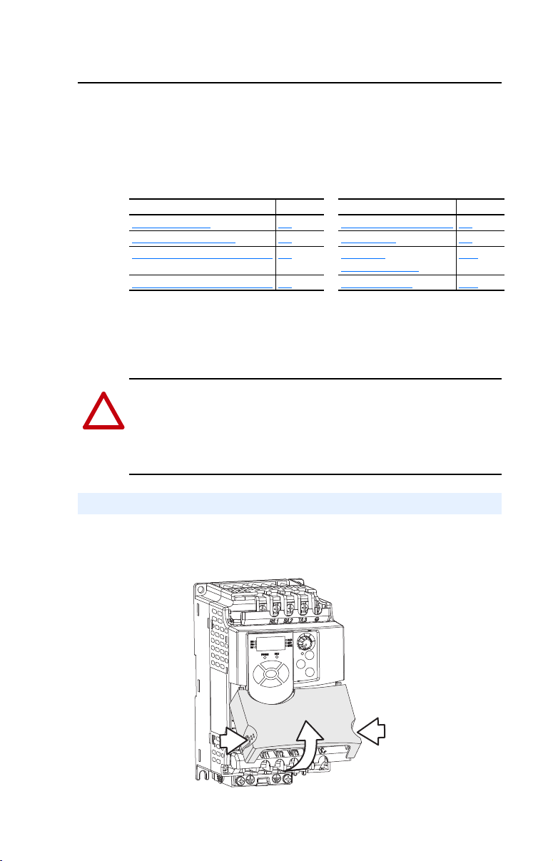
Opening the Cover
1. Press and hold in the tabs on each side of the cover.
2. Pull the cover out and up to release.
PowerFlex 4M Adjustable Frequency Drive FRN 1.xx - 2.xx User Manual
Publication 22F-UM001D-EN-E
Page 12
1-2 Installation/Wiring
76.2 mm (3.0 in.)
76.2 mm (3.0 in.)
Closest object that
may obstruct air flow
through the drive
heat sink and chassis
76.2 mm (3.0 in.)
76.2 mm (3.0 in.)
Airflow
See Table 1.B
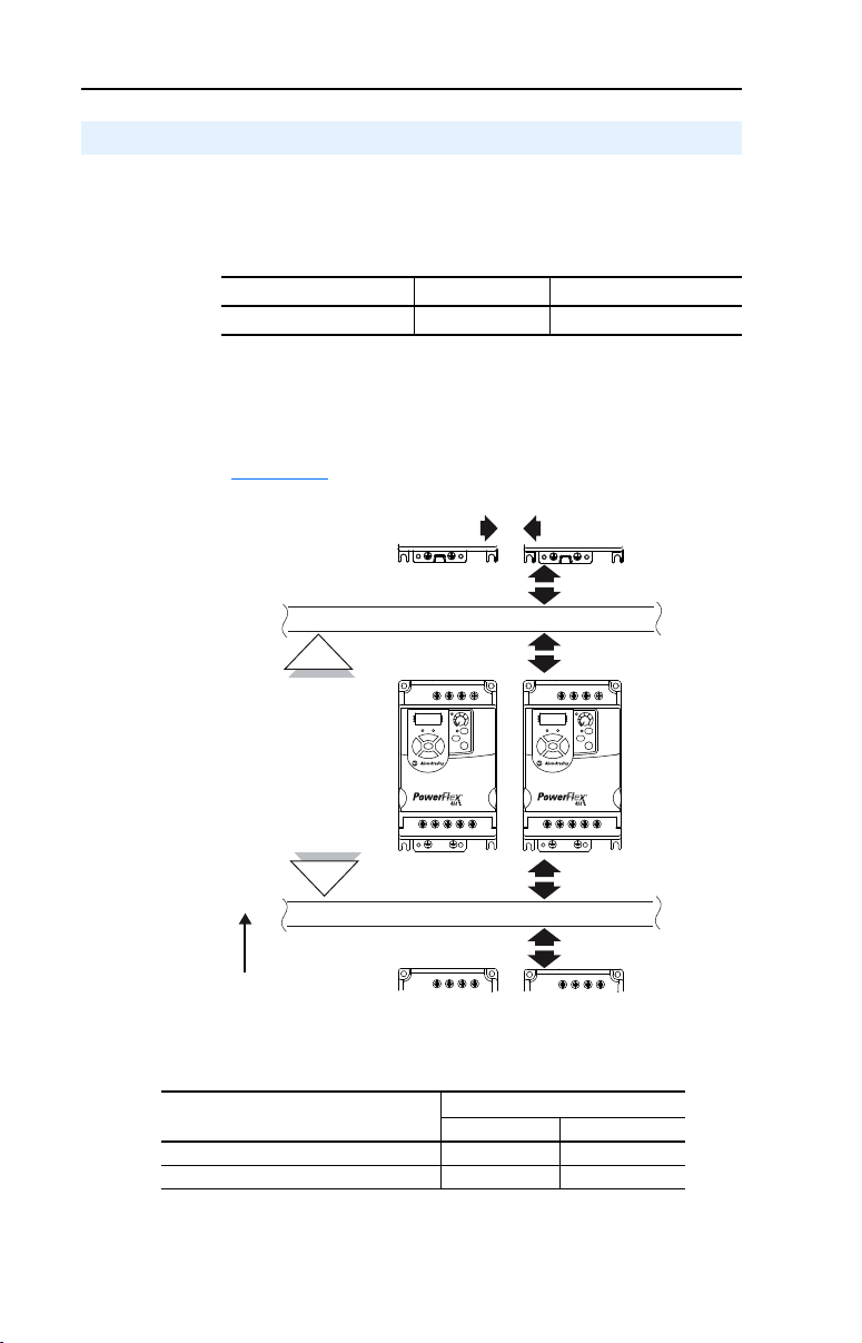
Mounting Considerations
• Mount the drive upright on a flat, vertical and level surface.
– Install on 35 mm DIN Rail (for frames A and B).
or
– Install with screws.
Table 1.A Screw Mounting Recommendations
Minimum Panel Thickness Screw Size Mounting Torque
1.9 mm (0.0747 in.) M4 (#8-32) 1.56-1.96 N-m (14-17 lb.-in.)
• Protect the cooling fan by avoiding dust or metallic particles.
• Do not expose to a corrosive atmosphere.
• Protect from moisture and direct sunlight.
Minimum Mounting Clearances
Refer to Appendix B for mounting dimensions.
Ambient Operating Temperatures
Table 1.B Enclosure and Clearance Requirements
Horizontal Clearance between drives
0 mm and greater -10°C (14°F) 40°C (104°F)
25 mm and greater -10°C (14°F) 50°C (122°F)
Drive enclosure is rated IP20, NEMA/UL Type Open.
PowerFlex 4M Adjustable Frequency Drive FRN 1.xx - 2.xx User Manual
Publication 22F-UM001D-EN-E
Minimum Maximum
Ambient Temperature
Page 13
Installation/Wiring 1-3
!
Important:
Tighten screw after
jumper removal.
Storage
• Store within an ambient temperature range of -40° to +85°C.
• Store within a relative humidity range of 0% to 95%,
non-condensing.
• Do not expose to a corrosive atmosphere.
AC Supply Source Considerations
Ungrounded Distribution Systems
ATTENTION: PowerFlex 4M drives contain protective MOVs that
are referenced to ground. These devices must be disconnected if the
drive is installed on an ungrounded or resistive grounded distribution
system.
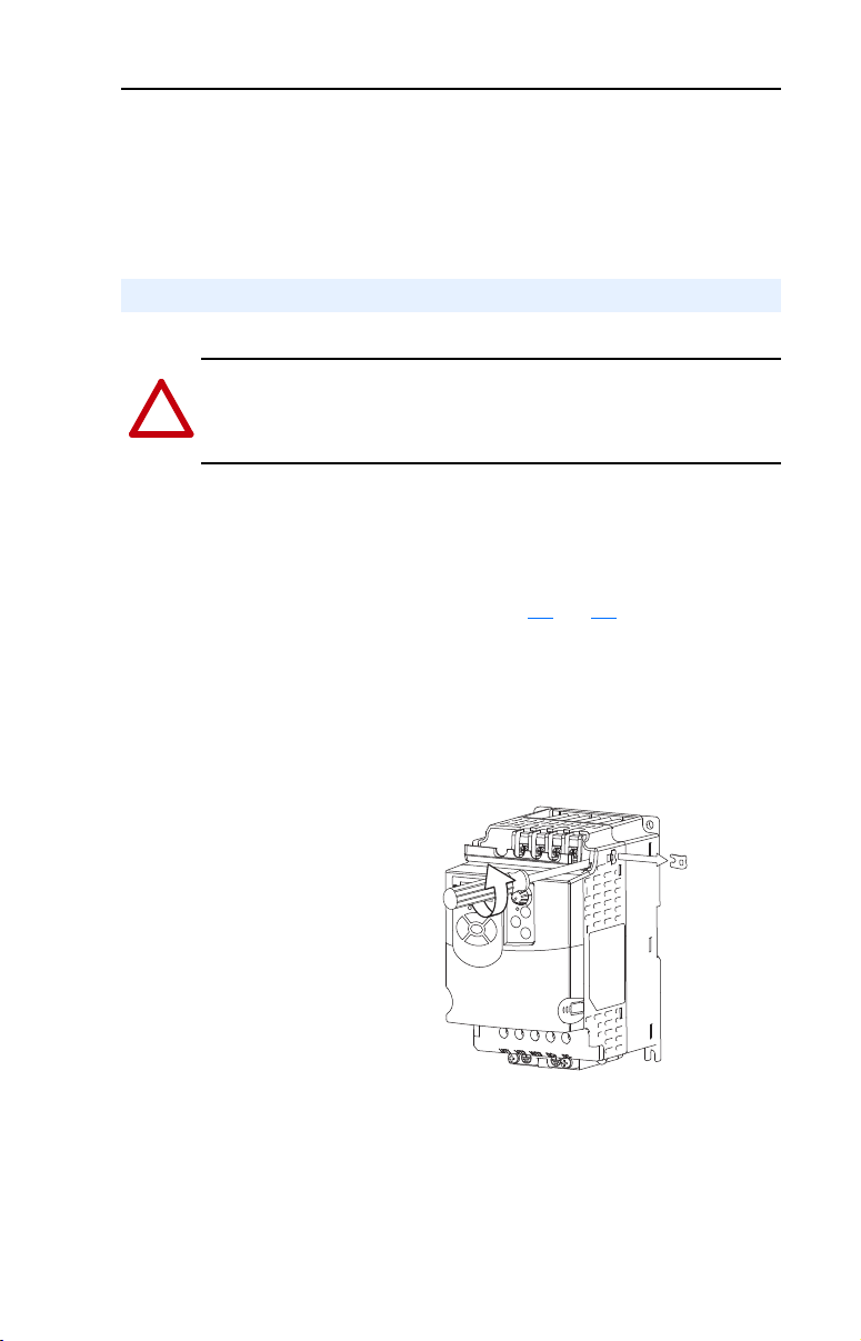
Disconnecting MOVs
To prevent drive damage, the MOVs connected to ground shall be
disconnected if the drive is installed on an ungrounded distribution
system where the line-to-ground voltages on any phase could exceed
125% of the nominal line-to-line voltage. To disconnect these devices,
remove the jumper shown in the Figures 1.1
1. Turn the screw counterclockwise to loosen.
2. Pull the jumper completely out of the drive chassis.
3. Tighten the screw to keep it in place.
and 1.2.
Figure 1.1 Jumper Location (Frame A shown)
PowerFlex 4M Adjustable Frequency Drive FRN 1.xx - 2.xx User Manual
Publication 22F-UM001D-EN-E
Page 14
1-4 Installation/Wiring
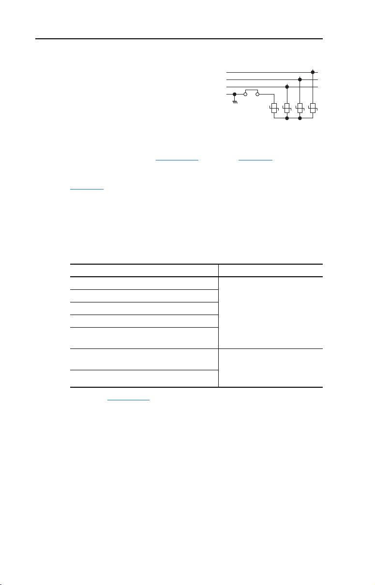
Figure 1.2 Phase to Ground MOV Removal
Input Power Conditioning
The drive is suitable for direct connection to input power within the rated
voltage of the drive (see Appendix
input power conditions which may cause component damage or
reduction in product life. If any of the conditions exist, as described in
Table 1.C
Action on the line side of the drive.
Important: Only one device per branch circuit is required. It should be
Table 1.C Input Power Conditions
, install one of the devices listed under the heading Corrective
mounted closest to the branch and sized to handle the total
current of the branch circuit.
AC Input
R/L1
S/L2
T/L3
Jumper
123
Three-Phase
A). Listed in Table 1.C are certain
4
Input Power Condition Corrective Action
Low Line Impedance (less than 1% line reactance) • Install Line Reactor
Greater than 120 kVA supply transformer
• or Isolation Transformer
Line has power factor correction capacitors
Line has frequent power interruptions
Line has intermittent noise spikes in excess of
6000V (lightning)
Phase to ground voltage exceeds 125% of normal
line to line voltage
Ungrounded distribution system
(1)
Refer to Appendix B for accessory ordering information.
• Remove MOV jumper to ground.
• or Install Isolation Transformer
with grounded secondary if
necessary.
(1)
PowerFlex 4M Adjustable Frequency Drive FRN 1.xx - 2.xx User Manual
Publication 22F-UM001D-EN-E
Page 15
Installation/Wiring 1-5
R/L1
S/L2
T/L3
U/T1
V/T2
W/T3
SHLD
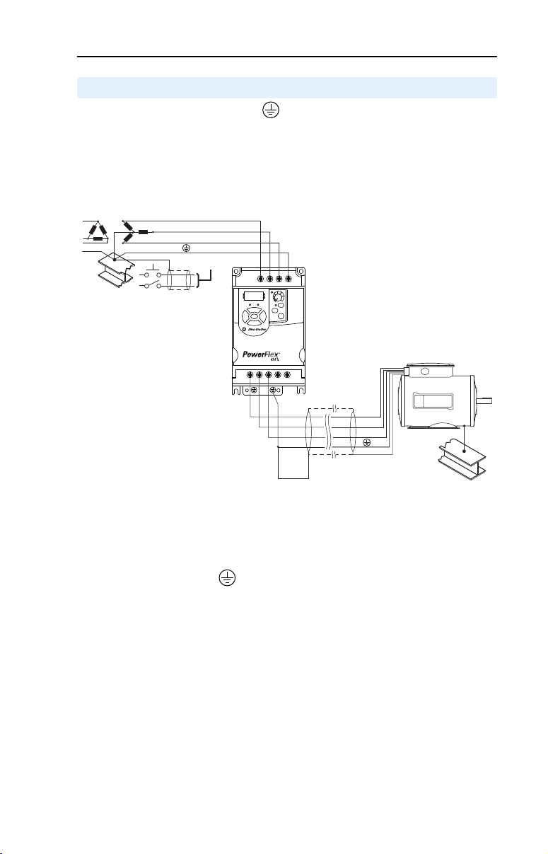
General Grounding Requirements
The drive Safety Ground - (PE) must be connected to system ground.
Ground impedance must conform to the requirements of national and
local industrial safety regulations and/or electrical codes. The integrity
of all ground connections should be periodically checked.
Figure 1.3 Typical Grounding
Ground Fault Monitoring
If a system ground fault monitor (RCD) is to be used, only Type B
(adjustable) devices should be used to avoid nuisance tripping.
Safety Ground - (PE)
This is the safety ground for the drive that is required by code. One of
these points must be connected to adjacent building steel (girder, joist), a
floor ground rod or bus bar. Grounding points must comply with national
and local industrial safety regulations and/or electrical codes.
Motor Ground
The motor ground must be connected to one of the ground terminals on
the drive.
PowerFlex 4M Adjustable Frequency Drive FRN 1.xx - 2.xx User Manual
Publication 22F-UM001D-EN-E
Page 16

1-6 Installation/Wiring
Shield Termination - SHLD
Either of the safety ground terminals located on the power terminal
block provides a grounding point for the motor cable shield. The motor
cable shield connected to one of these terminals (drive end) should also
be connected to the motor frame (motor end). Use a shield terminating or
EMI clamp to connect the shield to the safety ground terminal. The
conduit box option may be used with a cable clamp for a grounding point
for the cable shield.
When shielded cable is used for control and signal wiring, the shield
should be grounded at the source end only, not at the drive end.
RFI Filter Grounding
Using single phase drives with integral filter, or an external filter with
any drive rating, may result in relatively high ground leakage currents.
Therefore, the filter must only be used in installations with grounded
AC supply systems and be permanently installed and solidly
grounded (bonded) to the building power distribution ground. Ensure
that the incoming supply neutral is solidly connected (bonded) to the
same building power distribution ground. Grounding must not rely on
flexible cables and should not include any form of plug or socket that
would permit inadvertent disconnection. Some local codes may require
redundant ground connections. The integrity of all connections should be
periodically checked.
PowerFlex 4M Adjustable Frequency Drive FRN 1.xx - 2.xx User Manual
Publication 22F-UM001D-EN-E
Page 17

Installation/Wiring 1-7
!
Fuses and Circuit Breakers
The PowerFlex 4M does not provide branch short circuit protection. This
product should be installed with either input fuses or an input circuit
breaker. National and local industrial safety regulations and/or electrical
codes may determine additional requirements for these installations.
ATTENTION: To guard against personal injury and/or equipment
damage caused by improper fusing or circuit breaker selection, use only
the recommended line fuses/circuit breakers specified in this section.
Fusing
The PowerFlex 4M has been UL tested and approved for use with input
fuses. The ratings in the table that follows are the maximum
recommended values for use with each drive rating. The devices listed in
this table are provided to serve as a guide.
Bulletin 140M (Self-Protected Combination Controller)/UL489
Circuit Breakers
When using Bulletin 140M or UL489 rated circuit breakers, the
guidelines listed below must be followed in order to meet the NEC
requirements for branch circuit protection.
• Bulletin 140M can be used in single and group motor applications.
• Bulletin 140M can be used up stream from the drive without the
need for fuses.
PowerFlex 4M Adjustable Frequency Drive FRN 1.xx - 2.xx User Manual
Publication 22F-UM001D-EN-E
Page 18

1-8 Installation/Wiring
Table 1.D Minimum Recommended Branch Circuit Protective Devices
(1)
(2) (3)
Voltage
Rating
120V AC –
1-Phase
240V AC –
1-Phase
240V AC –
3-Phase
480V AC –
3-Phase
(1)
(2)
(3)
Drive Rating
kW (HP)
0.2 (0.25)
0.4 (0.5)
0.75 (1.0)
1.1 (1.5)
0.2 (0.25)
0.4 (0.5)
0.75 (1.0)
1.5 (2.0)
2.2 (3.0)
0.2 (0.25)
0.4 (0.5)
0.75 (1.0)
1.5 (2.0)
2.2 (3.0)
3.7 (5.0)
5.5 (7.5)
7.5 (10.0)
0.4 (0.5)
0.75 (1.0)
1.5 (2.0)
2.2 (3.0)
3.7 (5.0)
5.5 (7.5)
7.5 (10.0)
11.0 (15.0)
Fuse Rating
Amps
10
15
30
40
10
10
15
35
40
3
6
10
15
25
35
45
60
3
6
10
10
15
25
30
50
Recommended Fuse Type: UL Class J, RK1, T or Type BS88; 600V (550V) or equivalent.
The AIC ratings of the Bulletin 140M Motor Protector Circuit Breakers may vary. See Bulletin 140M
Motor Protection Circuit Breakers Application Ratings.
Manual Self-Protected (Type E) Combination Motor Controller, UL listed for 208 Wye or Delta, 240
140M
Catalog No.
140M-C2E-C10
140M-C2E-C16
140M-D8E-C20
140M-F8E-C32
140M-C2E-B63
140M-C2E-C10
140M-C2E-C16
140M-D8E-C25
140M-F8E-C32
140M-C2E-B25
140M-C2E-B40
140M-C2E-B63
140M-C2E-C16
140M-D8E-C20
140M-F8E-C25
140M-F8E-C32
140M-F8E-C45
140M-C2E-B25
140M-C2E-B40
140M-C2E-C10
140M-C2E-C10
140M-C2E-C16
140M-D8E-C20
140M-F8E-C25
140M-F8E-C32
Wye or Delta, 480Y/277 or 600Y/347. Not UL listed for use on 480V or 600V Delta/Delta, corner
ground, or high-resistance ground systems.
(4)
When using a Manual Self-Protected (Type E) Combination Motor Controller, the drive must be
installed in a ventilated or non-ventilated enclosure with the minimum volume specified in this
column. Application specific thermal considerations may require a larger enclosure.
Recommended
MCS Contactors
Catalog No.
100-C09
100-C12
100-C23
100-C30
100-C09
100-C09
100-C12
100-C23
100-C30
100-C09
100-C09
100-C09
100-C12
100-C23
100-C23
100-C37
100-C60
100-C09
100-C09
100-C09
100-C09
100-C12
100-C23
100-C23
100-C30
Min. Enclosure
Vol um e
Inches
1655
1655
1655
1655
1655
1655
1655
1655
1655
1655
1655
1655
1655
1655
1655
3441
3441
1655
1655
1655
1655
1655
3441
3441
3441
(4)
3
PowerFlex 4M Adjustable Frequency Drive FRN 1.xx - 2.xx User Manual
Publication 22F-UM001D-EN-E
Page 19

Installation/Wiring 1-9
!
!
Power Wiring
ATTENTION: National Codes and standards (NEC, VDE, BSI, etc.)
and local codes outline provisions for safely installing electrical
equipment. Installation must comply with specifications regarding wire
types, conductor sizes, branch circuit protection and disconnect
devices. Failure to do so may result in personal injury and/or equipment
damage.
ATTENTION: To avoid a possible shock hazard caused by induced
voltages, unused wires in the conduit must be grounded at both ends.
For the same reason, if a drive sharing a conduit is being serviced or
installed, all drives using this conduit should be disabled. This will help
minimize the possible shock hazard from “cross coupled” power leads.
Motor Cable Types Acceptable for 200-600 Volt Installations
General
A variety of cable types are acceptable for drive installations. For many
installations, unshielded cable is adequate, provided it can be separated
from sensitive circuits. As an approximate guide, allow a spacing of 0.3
meters (1 foot) for every 10 meters (32.8 feet) of length. In all cases,
long parallel runs must be avoided. Do not use cable with an insulation
thickness less than 15 mils (0.4 mm/0.015 in.). Do not route more than
three sets of motor leads in a single conduit to minimize “cross talk”. If
more than three drive/motor connections per conduit are required,
shielded cable must be used.
UL installations in 50°C ambient must use 600V, 75°C or 90°C wire.
UL installations in 40°C ambient should use 600V, 75°C or 90°C wire.
Use copper wire only. Wire gauge requirements and recommendations
are based on 75 degree C. Do not reduce wire gauge when using higher
temperature wire.
Unshielded
THHN, THWN or similar wire is acceptable for drive installation in dry
environments provided adequate free air space and/or conduit fill rates
limits are provided. Do not use THHN or similarly coated wire in wet
areas. Any wire chosen must have a minimum insulation thickness of
15 mils and should not have large variations in insulation concentricity.
PowerFlex 4M Adjustable Frequency Drive FRN 1.xx - 2.xx User Manual
Publication 22F-UM001D-EN-E
Page 20

1-10 Installation/Wiring
Shielded
Location Rating/Type Description
Standard
(Option 1)
Standard
(Option 2)
Class I & II;
Division I & II
600V, 75°C or 90°C (167°F
or 194°F) RHH/RHW-2
Belden 29501-29507 or
equivalent
Tray rated 600V, 75°C or
90°C (167°F or 194°F)
RHH/RHW-2
Shawflex 2ACD/3ACD or
equivalent
Tray rated 600V, 75°C or
90°C (167°F or 194°F)
RHH/RHW-2
• Four tinned copper conductors with XLPE insulation
• Foil shield and tinned copper drain wire with 85% braid
coverage
• PVC jacket
• Three tinned copper conductors with XLPE insulation
• 5 mil single helical copper tape (25% overlap min.)
with three bare copper grounds in contact with shield
• PVC jacket
• Three tinned copper conductors with XLPE insulation
• 5 mil single helical copper tape (25% overlap min.)
with three bare copper grounds in contact with shield
• PVC copper grounds on #10 AWG and smaller
Reflected Wave Protection
The drive should be installed as close to the motor as possible.
Installations with long motor cables may require the addition of external
devices to limit voltage reflections at the motor (reflected wave
phenomena). See Table 1.E
The reflected wave data applies to all frequencies 2 to 10 kHz.
For 240V ratings, reflected wave effects do not need to be considered.
Table 1.E Maximum Cable Length Recommendations
Reflected Wave
380-480V Ratings Motor Insulation Rating Motor Cable Only
(1)
Longer cable lengths can be achieved by installing devices on the output of the drive.
Consult factory for recommendations.
for recommendations.
1000 Vp-p 15 meters (49 feet)
1200 Vp-p 40 meters (131 feet)
1600 Vp-p 170 meters (558 feet)
(1)
Output Disconnect
The drive is intended to be commanded by control input signals that will
start and stop the motor. A device that routinely disconnects then
reapplies output power to the motor for the purpose of starting and
stopping the motor should not be used. If it is necessary to disconnect
power to the motor with the drive outputting power, an auxiliary contact
should be used to simultaneously disable drive control run commands.
PowerFlex 4M Adjustable Frequency Drive FRN 1.xx - 2.xx User Manual
Publication 22F-UM001D-EN-E
Page 21
Installation/Wiring 1-11
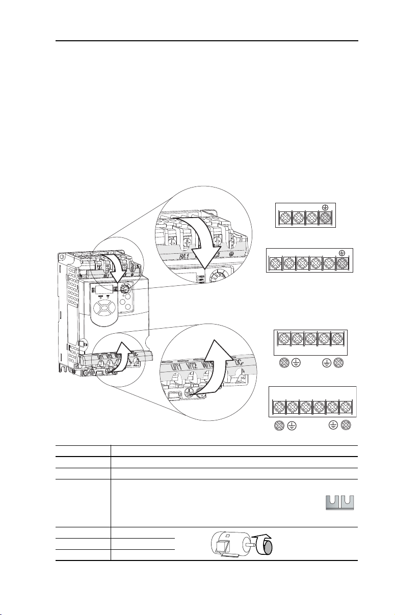
Power Terminal Block
The drive utilizes a finger guard over the power wiring terminals.
To remov e:
1. Press in and hold the locking tab.
2. For the finger guard on the top of the drive, slide it down and out.
For the finger guard at the bottom of the drive, slide it up and out.
Replace the finger guard when wiring is complete.
Figure 1.4 Power Terminal Block
Frame A and B
T/L3S/L2R/L1
Frame C
P1
T/L3S/L2R/L1
P2
Frame A and B
Terminal Description
R/L1, S/L2 1-Phase Input
R/L1, S/L2, T/L3 3-Phase Input
DC Bus Inductor Connection (Frame C drives only.)
P1
(1)
, P2
The Frame C drive is shipped with a jumper between Terminals P1
(1)
and P2. Remove this jumper only when a DC Bus Inductor will be
connected. Drive will not power up without a jumper or inductor
connected.
U/T1 To Motor U/T1
V/T2 To Motor V/T2
W/T3 To Motor W/T3
DC+
W/T3V/T2U/T1
DC-
Frame C
BR+
DC+
W/T3V/T2U/T1
DC-BR-
Switch any two motor
=
PowerFlex 4M Adjustable Frequency Drive FRN 1.xx - 2.xx User Manual
leads to change forward
direction.
Publication 22F-UM001D-EN-E
Page 22
1-12 Installation/Wiring
!
!
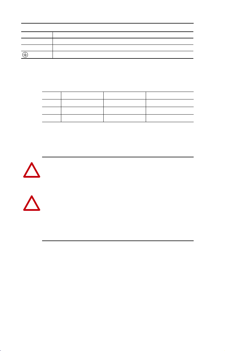
Terminal Description
(2)
DC+
BR+
(1)
(2)
(2)
, DC-
(1)
, BR-
For Frame C only [5.5 kW (7.5 HP) ratings and higher].
Not applicable to 120 V, 1-Phase drives.
DC Bus Connection
(1)
Dynamic Brake Resistor Connection
Safety Ground - PE
Table 1.F Power Terminal Block Specifications
Frame Maximum Wire Size
A 3.3 mm
B 8.4 mm
C 13.3 mm
(1)
Maximum/minimum sizes that the terminal block will accept - these are not
recommendations.
2
(12 AWG) 0.8 mm2 (18 AWG) 1.4-1.6 N-m (12-14 lb.-in.)
2
(8 AWG) 0.8 mm2 (18 AWG) 1.6-1.9 N-m (14-17 lb.-in.)
2
(6 AWG) 3.3 mm2 (12 AWG) 2.7-3.2 N-m (24-28 lb.-in.)
(1)
Motor Start/Stop Precautions
ATTENTION: A contactor or other device that routinely disconnects
and reapplies the AC line to the drive to start and stop the motor can
cause drive hardware damage. The drive is designed to use control input
signals that will start and stop the motor. If used, the input device must
not exceed one operation per minute or drive damage can occur.
ATTENTION: The drive start/stop control circuitry includes
solid-state components. If hazards due to accidental contact with
moving machinery or unintentional flow of liquid, gas or solids exist,
an additional hardwired stop circuit may be required to remove the AC
line to the drive. When the AC line is removed, there will be a loss of
any inherent regenerative braking effect that might be present - the
motor will coast to a stop. An auxiliary braking method may be
required.
Minimum Wire Size
(1)
Tor qu e
PowerFlex 4M Adjustable Frequency Drive FRN 1.xx - 2.xx User Manual
Publication 22F-UM001D-EN-E
Page 23
Installation/Wiring 1-13
!
I/O Wiring Recommendations
Important points to remember about I/O wiring:
• Always use copper wire.
• Wire with an insulation rating of 600V or greater is recommended.
• Control and signal wires should be separated from power wires by at
least 0.3 meters (1 foot).
Important: I/O terminals labeled “Common” are
not referenced to the
safety ground (PE) terminal and are designed to greatly
reduce common mode interference.
ATTENTION: Driving the 4-20mA analog input from a voltage
source could cause component damage. Verify proper configuration
prior to applying input signals.
Control Wire Types
Table 1.G Recommended Control and Signal Wire
Wire Type(s) Description Minimum
2
Belden 8760/9460
(or equiv.)
Belden 8770
(or equiv.)
(1)
If the wires are short and contained within a cabinet which has no sensitive circuits,
the use of shielded wire may not be necessary, but is always recommended.
(18AWG), twisted pair, 100%
0.8 mm
shield with drain.
0.8 mm
remote pot only.
(1)
2
(18AWG), 3 conductor, shielded for
(1)
Insulation Rating
300V
60 degrees C
(140 degrees F)
I/O Terminal Block
Table 1.H I/O Terminal Block Specifications
Maximum Wire Size
2
(16 AWG) 0.2 mm2 (24 AWG) 0.5-0.8 N-m (4.4-7 lb.-in.)
1.3 mm
(1)
Maximum/minimum sizes that the terminal block will accept - these are not
recommendations.
(1)
Minimum Wire Size
(1)
Torque
Maximum Control Wire Recommendations
Do not exceed control wiring length of 30 meters (100 feet). Control
signal cable length is highly dependent on electrical environment and
installation practices. To improve noise immunity, the I/O terminal block
Common must be connected to ground terminal/protective earth. If using
the RS485 (DSI) port, I/O Terminal 16 should also be connected to
ground terminal/protective earth.
PowerFlex 4M Adjustable Frequency Drive FRN 1.xx - 2.xx User Manual
Publication 22F-UM001D-EN-E
Page 24
1-14 Installation/Wiring
Potentiometer
must be
1-10k ohm
2 Watt Min.
30V DC 125V AC 240V AC
Resistive 3.0A 3.0A 3.0A
Inductive 0.5A 0.5A 0.5A
(1)
Important: I/O Terminal 01 is always a coast to stop input except
when P106 [Start Source] is set to “3-Wire” control. In three wire
control, I/O Terminal 01 is controlled by P107 [Stop Mode]. All other
stop sources are controlled by P107 [Stop Mode].
Important: The drive is shipped with a ju mper installed between I/O
Terminals 01 and 11. Remove this jumper when using I/O Terminal
01 as a stop or enable input.
(2)
Two wire control shown. For three wire control use a momentary
input on I/O Terminal 02 to command a start. Use a
maintained input for I/O Terminal 03 to change direction.
P106
[Start Source]
Stop
I/O Terminal 01
Stop
Keypad Per P107 Coast
3-Wir e Per P 107 Per P107
2-Wire Per P107 Coast
RS485 Port Per P107 Coast
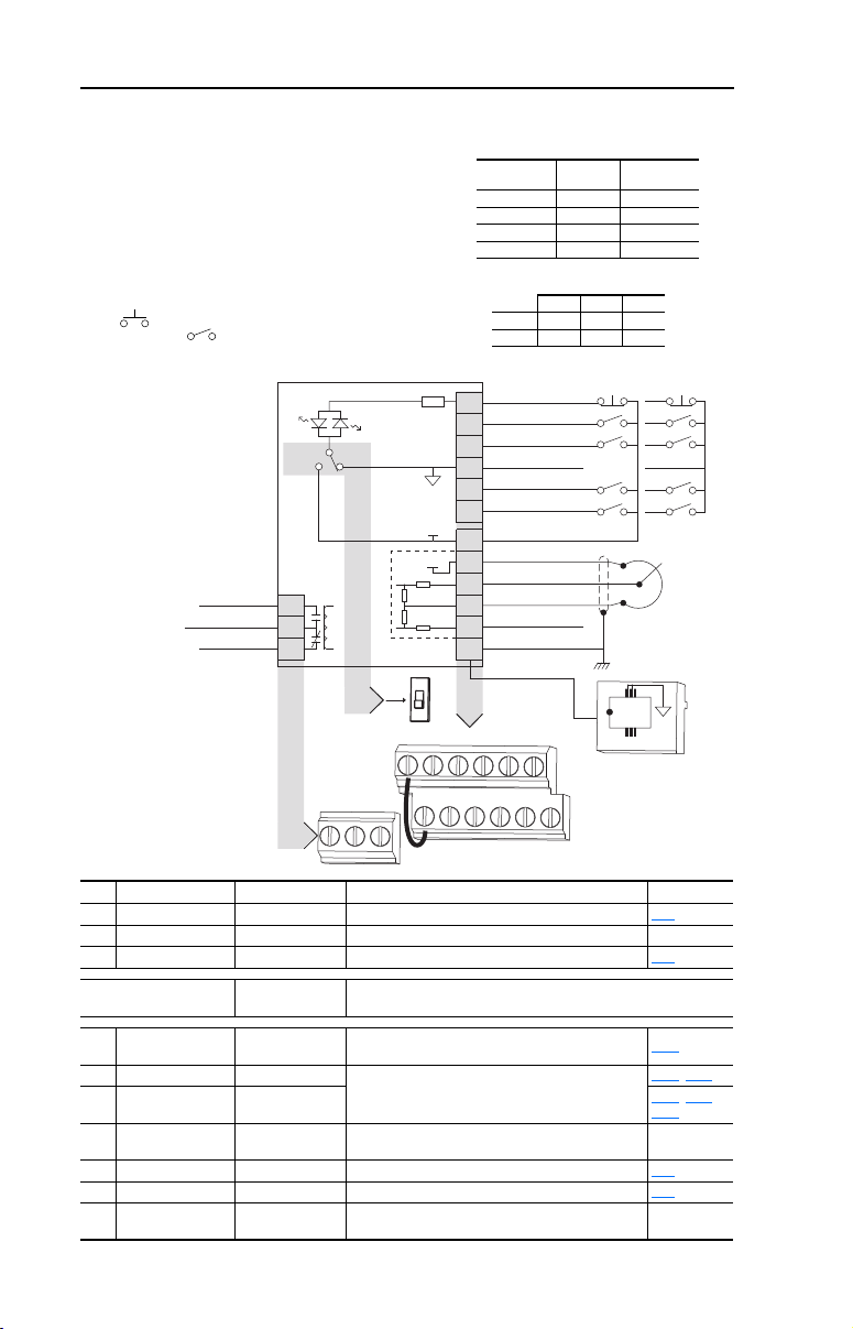
Figure 1.5 Control Wiring Block Diagram
SRCSNK
Relay N.O.
Relay Common
Relay N.C.
R1
R2
R3
R1 R2 R3
No. Signal Default Description Param.
R1 Relay N.O. Fault Normally open contact for output relay. t221
R2 Relay Common – Common for output relay.
R3 Relay N.C. Fault Normally closed contact for output relay. t221
Sink/Source DIP Switch Source (SRC)
01 Stop
(1)
Coast
02 Start/Run FWD Not Active
03 Direction/Run REV Not Active
04 Digital Common –
Inputs can be wired as Sink (SNK) or Source (SRC) via DIP Switch
setting.
The factory installed jumper or a normally closed input
must be present for the drive to start.
Command comes from the integral keypad by default. To
disable reverse operation, see A095 [Reverse Disable].
For digital inputs. Electronically isol ated with digital inputs
from analog I/O.
05 Digital Input 1 Preset Freq Program with t201 [Digital In1 Sel]. t201
06 Digital Input 2 Preset Freq Program with t202 [Digital In2 Sel]. t202
11 +24V DC –
Drive supplied power for digital inputs.
Maximum output current is 100mA.
Stop
01
Start/Run FWD
02
Direction/Run REV
03
Digital Common
04
Digital Input 1
05
Digital Input 2
06
+24V
+10V
SNK
SRC
01 02 03 04 05 06
11 12 13 14 15 16
+24V DC
11
+10V DC
12
0-10V In
13
Analog Common
14
4-20mA In
15
RS485 Shield
16
(1)
(1)
SRC Wiring
(2)
Typical
RS485
(DSI)
Typical
SNK Wiring
18
P106
P106, P107
P106
A434
(1)
, P107,
PowerFlex 4M Adjustable Frequency Drive FRN 1.xx - 2.xx User Manual
Publication 22F-UM001D-EN-E
Page 25
Installation/Wiring 1-15
13
14
+
Common
No. Signal Default Description Param.
12 +10V DC –
13 0-10V In
14 Analog Common –
15 4-20mA In
16 RS485 (DSI) Shield –
(3)
(3)
Only one analog frequency source may be connected at a time. If more than one reference is connected at the same
time, an undetermined frequency reference will result.
Not Active
(3)
Not Active
Drive supplied power for 0-10V external potentiometer.
Maximum output current is 15mA.
For external 0-10V input supply
(input impedance = 100k ohm) or potentiometer wiper.
For 0-10V In or 4-20mA In. Electronically isolated with
analog inputs from digital I/O.
For external 4-20mA input supply
(input impedance = 250 ohm).
Terminal should be connected to safety ground - PE
when using the RS485 (DSI) communications port.
P108
P108
P108
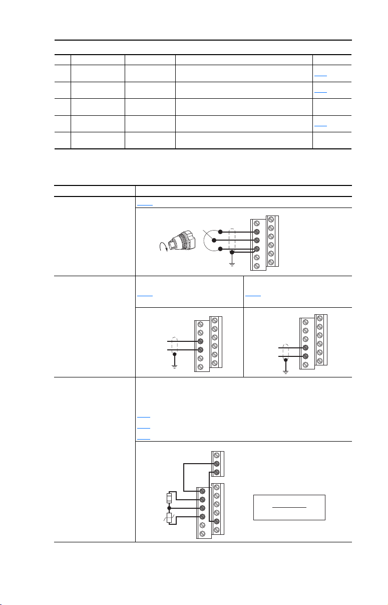
I/O Wiring Examples
Input Connection Example
Potentiometer
1-10k Ohm Pot.
Recommended
(2 Watt minimum)
Analog Input
0 to +10V, 100k ohm
impedance
4-20 mA, 100 ohm
impedance
[Speed Reference] = 2 “0-10V Input”
P108
Voltage
P108
[Speed Reference] = 2 “0-10V
Input”
12
13
14
Current
P108 [Speed Reference] = 3
“4-20mA Input”
Common
14
15
+
Analog Input, PTC
For Drive Fault
Wire the PTC and External Resistor (typically matched to the PTC Hot
Resistance) to I/O Terminals 12, 13, 14.
Wire R2/R3 Relay Output (SRC) to I/O Terminals 5 & 11.
[Digital In1 Sel] = 3 “Aux Fault”
t201
[Relay Out Sel] = 10 “Above Anlg V”
t221
t222
[Relay Out Level] = % Voltage Trip
R2
R3
11
R
e
R
PTC
12
13
14
05
PowerFlex 4M Adjustable Frequency Drive FRN 1.xx - 2.xx User Manual
R
PTC (hot)
V
=
Tri p
R
PTC (hot)
+ R
×
100
e
Publication 22F-UM001D-EN-E
Page 26
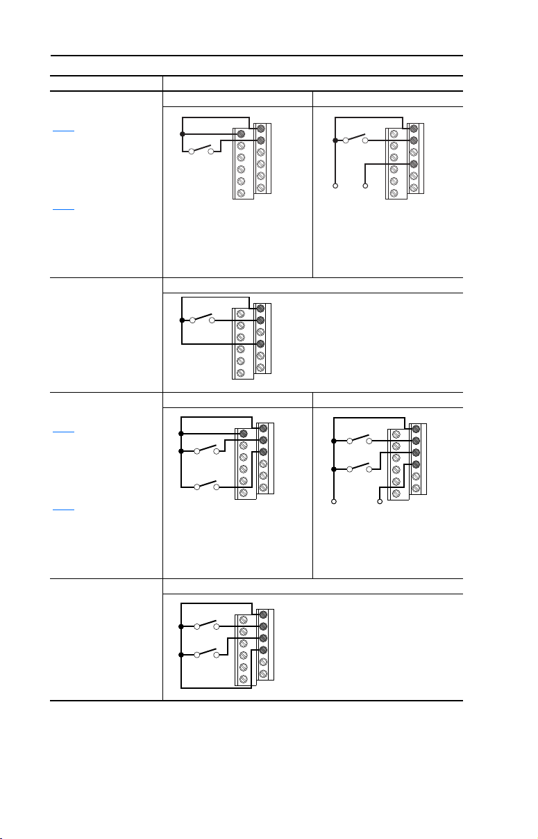
1-16 Installation/Wiring
11
01
02
Stop-Run
01
02
04
Stop-Run
11
01
02
03
Stop-Run
Forward
Stop-Run
Reverse
Common
01
02
03
04
Stop-Run
Forward
Stop-Run
Reverse
+24V
Each digital input draws 6 mA.
Stop-Run
Forward
Stop-Run
Reverse
01
02
03
04
Input Connection Example
2 Wire SRC Control -
Non-Reversing
[Start Source] = 2, 3
P106
or 4
Input must be active for
the drive to run. When
input is opened, the drive
will stop as specified by
[Stop Mode].
P107
If desired, a User Supplied
24V DC power source can
be used. Refer to the
“External Supply (SRC)”
example.
2 Wire SNK Control Non-Reversing
Internal Supply (SRC) External Supply (SRC)
Internal Supply (SNK)
01
Stop-Run
+24V Common
02
04
Each digital input draws 6 mA.
2 Wire SRC Control Run FWD/Run REV
[Start Source] = 2, 3
P106
or 4
Input must be active for
the drive to run. When
input is opened, the drive
will stop as specified by
[Stop Mode].
P107
If both Run Forward and
Run Reverse inputs are
closed at the same time,
an undetermined state
could occur.
2 Wire SNK Control Run FWD/Run REV
PowerFlex 4M Adjustable Frequency Drive FRN 1.xx - 2.xx User Manual
Publication 22F-UM001D-EN-E
Internal Supply (SRC) External Supply (SRC)
Internal Supply (SNK)
Page 27
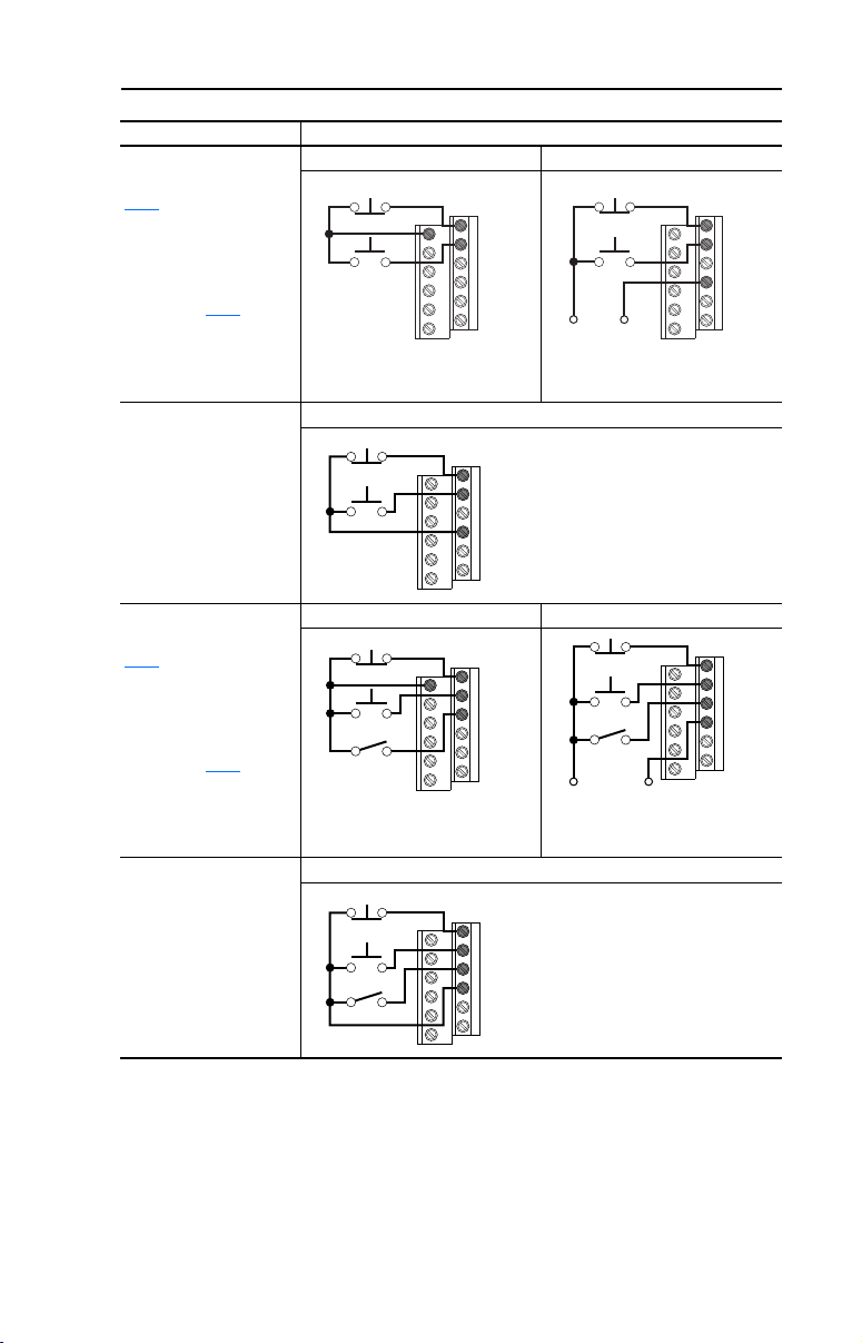
Input Connection Example
Each digital input draws 6 mA.
Stop
Start
01
02
03
04
11
01
02
03
Stop
Start
Direction
+24V Common
Stop
Start
Direction
01
02
03
04
Each digital input draws 6 mA.
Stop
Start
Direction
01
02
03
04
3 Wire SRC Control -
Internal Supply (SRC) External Supply (SRC)
Non-Reversing
[Start Source] = 1
P106
A momentary input will
Stop
11
start the drive. A stop
input to I/O Terminal 01
will stop the drive as
specified by P107
[Stop
Start
Mode].
Installation/Wiring 1-17
+24V
Stop
Start
Common
01
02
04
01
02
3 Wire SNK Control Non-Reversing
3 Wire SRC Control Reversing
[Start Source] = 1
P106
A momentary input will
start the drive. A stop
input to I/O Terminal 01
will stop the drive as
specified by P107
[Stop
Mode]. I/O Terminal 03
determines direction.
3 Wire SNK Control Reversing
Internal Supply (SNK)
Internal Supply (SRC) External Supply (SRC)
Internal Supply (SNK)
PowerFlex 4M Adjustable Frequency Drive FRN 1.xx - 2.xx User Manual
Publication 22F-UM001D-EN-E
Page 28
1-18 Installation/Wiring
04
Customer Inputs
Optional Ground Connection
02 0402 0402 0402
!
ATTENTION: Digital inputs on multiple drives should not be
tied together when using SNK (Internal Supply) mode. In SNK
mode, if power is removed from one drive, inadvertent operation
of other drives that share the same I/O Common connection
may occur.
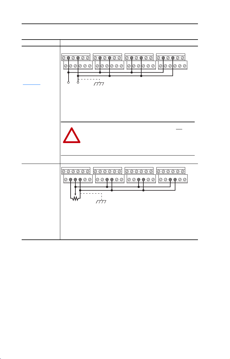
Typical Multiple Drive Connection Examples
Input Connection Example
Multiple Digital
Input Connections
Customer Inputs can
be wired per
External Supply
(SRC) examples on
.
page 1-16
When connecting a single input such as Run, Stop, Reverse or Preset Speeds
to multiple drives, it is important to connect I/O Terminal 04 common together
for all drives. If they are to be tied into another common (such as earth ground
or separate apparatus ground) only one point of the daisy chain of I/O Terminal
04 should be connected.
Multiple Analog
Connections
12 13 14 13 14 13 14 13 14
Remote Potentiometer Optional Ground Connection
When connecting a single potentiometer to multiple drives it is important to
connect I/O Terminal 14 common together for all drives. I/O Terminal 14
common and I/O Terminal 13 (potentiometer wiper) should be daisy-chained to
each drive. All drives must be powered up for the analog signal to be read
correctly.
PowerFlex 4M Adjustable Frequency Drive FRN 1.xx - 2.xx User Manual
Publication 22F-UM001D-EN-E
Page 29
Installation/Wiring 1-19
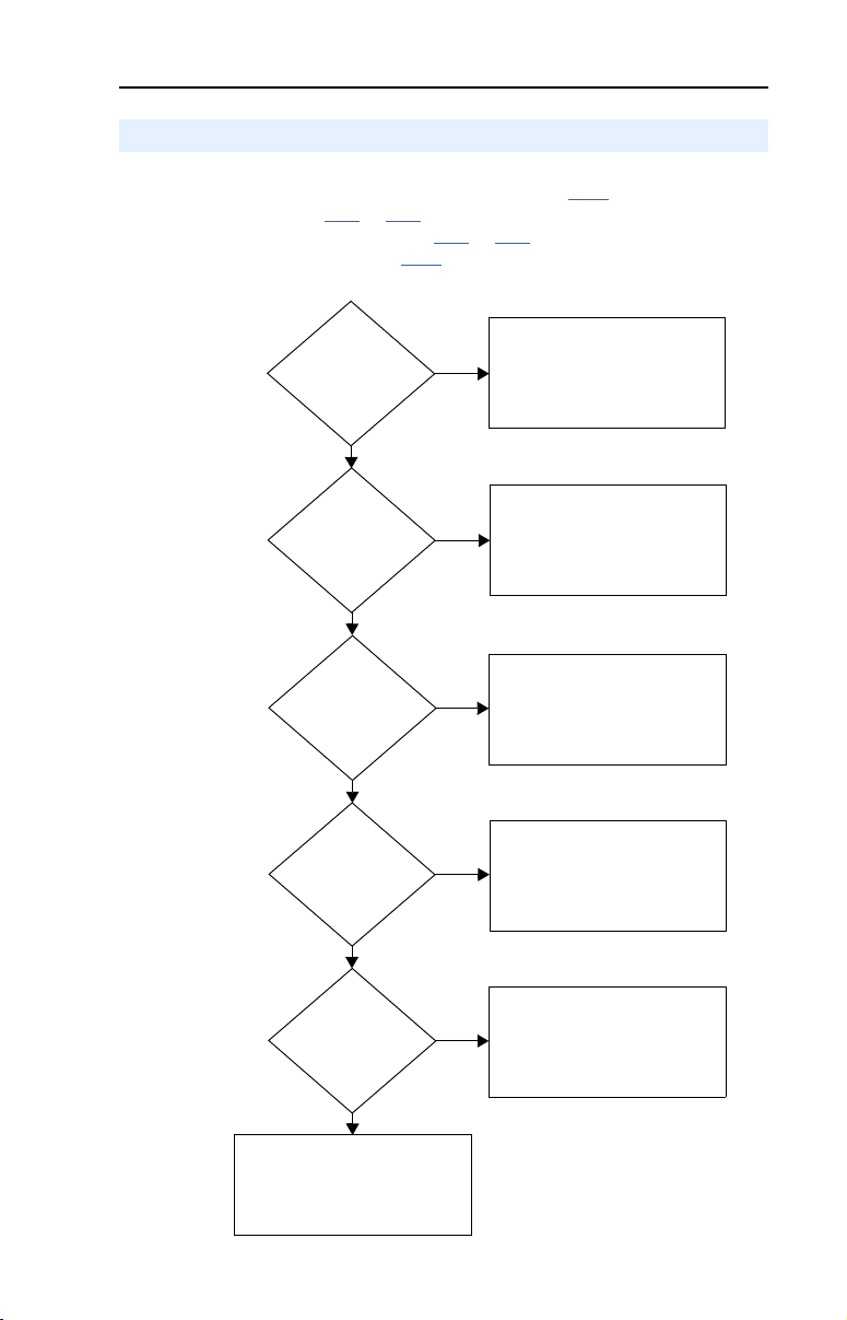
Jog Input
Enabled and Active:
t201 or t202 = 2
Ye s
Drive will Start and Run at Jog Speed.
Direction comes from
Terminal 03 Dir/Run REV
Local/Remote Input
Enabled and Active:
t201 or t202 = 5
Ye s
Start, Speed and Direction commands
come from Integral Keypad.
Comm Select Input
Enabled and Active:
t201 or t202 = 6
Ye s
Start, Speed and Direction commands
come from RS485 (DSI) port.
P108 [Speed Reference]
= 4 or 5
Ye s
Run as specified by
P108 [Speed Reference].
Start and Direction commands come
from P106 [Start Source].
t201 / t202
Preset Inputs Active
Ye s
Run as specified by
A411-A413 [Preset Freq 1-3].
Start and Direction commands come
from P106 [Start Source].
Run as specified by
P108 [Speed Reference].
Start and Direction commands
come from P106 [Start Source].
No
No
No
No
No
Start and Speed Reference Control
The drive speed command can be obtained from a number of different
sources. The source is normally determined by P108
However, when t201
and the digital input is active, t201
reference commanded by P108
or t202 Digital Inx Sel is set to option 2, 4, 5 or 6,
or t202 will override the speed
[Speed Reference]. See the chart below
for the override priority.
[Speed Reference].
PowerFlex 4M Adjustable Frequency Drive FRN 1.xx - 2.xx User Manual
Publication 22F-UM001D-EN-E
Page 30
1-20 Installation/Wiring
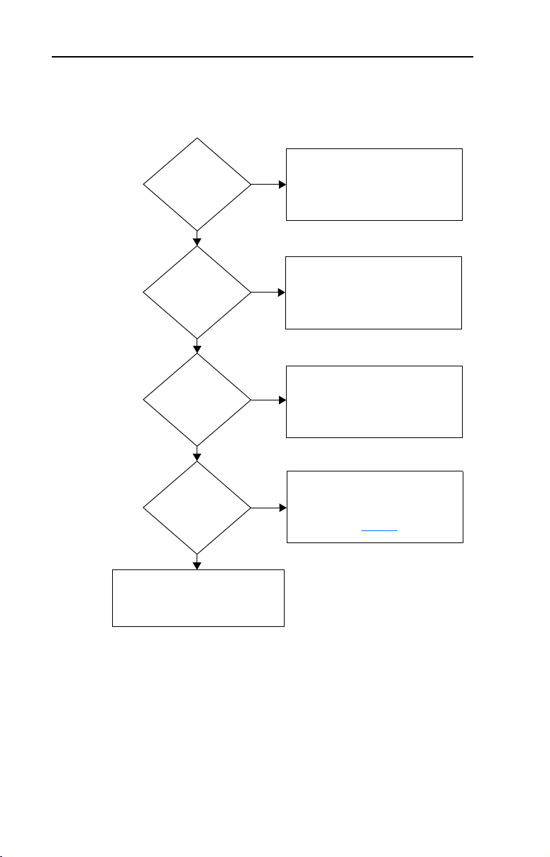
Jog Input
Enabled and Active:
t201 or t202 = 2
Ye s
A405 [Jog Accel/Decel] used.
P109 [Accel Time 1]/P110 [Decel Time 1]
are used.
RS485 (DSI) Port
Controls Speed
Active when
A401 [Accel Time 2]/A402 [Decel Time 2]
is selected by RS485 (DSI) port.
Input is programmed
as “Accel 2 & Decel 2”
t201 or t202 = 1
A401 [Accel Time 2]/A402 [Decel Time 2]
is active when input is active.
Speed is controlled
by [Preset Freq x]
t201 or t202 = 4
P109 [Accel Time 1]/P110 [Decel Time 1];
A401 [Accel Time 2]/A402 [Decel Time 2]
determined by the active Preset Frequency.
See A410-A413 [Preset Freq 0-3]
on page 3-21
.
No
No
Ye s
Ye s
Ye s
No
No
Accel/Decel Selection
The selection of Accel/Decel rates can be made through digital inputs,
RS485 (DSI) communications and/or parameters.
PowerFlex 4M Adjustable Frequency Drive FRN 1.xx - 2.xx User Manual
Publication 22F-UM001D-EN-E
Page 31

Installation/Wiring 1-21
EMC Instructions
CE Conformity
Conformity with the Low Voltage (LV) Directive and Electromagnetic
Compatibility (EMC) Directive has been demonstrated using
harmonized European Norm (EN) standards published in the Official
Journal of the European Communities. PowerFlex Drives comply with
the EN standards listed below when installed according to the User
Manual.
CE Declarations of Conformity are available online at:
http://www.ab.com/certification/ce/docs.
Low Voltage Directive (73/23/EEC)
• EN50178 Electronic equipment for use in power installations
EMC Directive (89/336/EEC)
• EN61800-3 Adjustable speed electrical power drive systems Part 3:
EMC product standard including specific test methods.
General Notes
• The motor cable should be kept as short as possible in order to avoid
electromagnetic emission as well as capacitive currents.
• Use of line filters in ungrounded systems is not recommended.
• Conformity of the drive with CE EMC requirements does not
guarantee an entire machine installation complies with CE EMC
requirements. Many factors can influence total machine/installation
compliance.
PowerFlex 4M Adjustable Frequency Drive FRN 1.xx - 2.xx User Manual
Publication 22F-UM001D-EN-E
Page 32

1-22 Installation/Wiring
U/T1
V/T2
W/T3
EMI Fittings and Metal Conduit
Shielded Enclosure
(1)
Building Structure Steel
Enclosure Ground Connection
R/L1
S/L2
T/L3
(2)
EMI Filter
L1'
L2'
L3'
L1
L2
L3
Shielded Motor Cable
Esc
Sel
Essential Requirements for CE Compliance
Conditions 1-3 listed below must be satisfied for PowerFlex drives to
meet the requirements of EN61800-3.
1. Grounding as described in Figure 1.6
. Refer to page 1-6 for
additional grounding recommendations.
2. Output power, control (I/O) and signal wiring must be braided,
shielded cable with a coverage of 75% or better, metal conduit or
equivalent attenuation.
3. Allowable cable length in Table 1.I
Table 1.I Allowable Cable Length
Filter Type EN61800-3
Integral, 240V 5 meters (16 feet) 5 meters (16 feet) 1 meter (3 feet)
Integral, 480V 10 meters (33 feet)
External - S Type
External - L Type
(1)
Refer to Appendix B for details on optional external filters.
(2)
Equivalent to EN55011 Class A.
(3)
Equivalent to EN55011 Class B.
Figure 1.6 Connections and Grounding
Second
Environment
(1)
5 meters (16 feet) 5 meters (16 feet) 1 meter (3 feet)
(1)
100 meters (328 feet) 100 meters (328 feet) 25 meters (82 feet)
is not exceeded.
EN61800-3 First
Environment
Restricted
Distribution
––
(2)
EN61800-3 First
Environment
Unrestricted
Distribution
(3)
(1)
First Environment Unrestricted Distribution installations require a shielded enclosure.
Keep wire length as short as possible between the enclosure entry point and the EMI
filter.
(2)
Integral EMI filters are available on 240V, 1-Phase drives and 380V, 3-Phase drives.
PowerFlex 4M Adjustable Frequency Drive FRN 1.xx - 2.xx User Manual
Publication 22F-UM001D-EN-E
Page 33

Installation/Wiring 1-23
EN61000-3-2
• 0.75 kW (1 HP) 240V 1-Phase and 3-Phase drives and
0.4 kW (0.5 HP) 240V 1-Phase drives are suitable for installation on
a private low voltage power network. Installations on a public low
voltage power network may require additional external harmonic
mitigation.
• Other drive ratings meet the current harmonic requirements of
EN61000-3-2 without additional external mitigation.
PowerFlex 4M Adjustable Frequency Drive FRN 1.xx - 2.xx User Manual
Publication 22F-UM001D-EN-E
Page 34

1-24 Installation/Wiring
Notes:
PowerFlex 4M Adjustable Frequency Drive FRN 1.xx - 2.xx User Manual
Publication 22F-UM001D-EN-E
Page 35

Chapter 2
!
Start Up
This chapter describes how to start up the PowerFlex 4M Drive. To
simplify drive setup, the most commonly programmed parameters are
organized in a single Basic Program Group.
Important: Read the Gener
ATTENTION: Power must be applied to the drive to perform the
following start-up procedures. Some of the voltages present are at
incoming line potential. To avoid electric shock hazard or damage to
equipment, only qualified service personnel should perform the
following procedure. Thoroughly read and understand the procedure
before beginning. If an event does not occur while performing this
procedure, Do Not Proceed. Remove All Power including user
supplied control voltages. User supplied voltages may exist even when
main AC power is not applied to the drive. Correct the malfunction
before continuing.
al Precautions section before proceeding.
Prepare For Drive Start-Up
Before Applying Power to the Drive
❏ 1. Confirm that all inputs are connected to the correct terminals and are
secure.
❏ 2. Verify that AC line power at the disconnect device is within the rated
value of the drive.
❏ 3. Verify that any digital control power is 24 volts.
❏ 4. Verify that the Sink (SNK)/Source (SRC) Setup DIP Switch is set to
match your control wiring scheme. See Figure 1.5 on page 1-14 for
location.
Important: The def
ault control scheme is Source (SRC). The Stop
terminal is jumpered (I/O Terminals 01 and 11) to allow
starting from the keypad. If the control scheme is changed
to Sink (SNK), the jumper must be removed from I/O
Terminals 01 and 11 and installed between I/O Terminals
01 and 04.
❏ 5. Verify that the Stop input is present or the drive will not start.
Important: If I/O T
erminal 01 is used as a stop input, the jumper
between I/O Terminals 01 and 11 must be removed.
PowerFlex 4M Adjustable Frequency Drive FRN 1.xx - 2.xx User Manual
Publication 22F-UM001D-EN-E
Page 36

2-2 Start Up
Applying Power to the Drive
❏ 6. Apply AC power and control voltages to the drive.
❏ 7. Familiarize yourself with the integral keypad features (see page 2-3)
before setting any Program Grou
Start, Stop, Direction and Speed Control
Factory default parameter values allow the drive to be controlled from
the integral keypad. No programming is required to start, stop, change
direction and control speed directly from the integral keypad.
p parameters.
Important: T
If a fault appears on power up, refer to Fault Descriptions on page 4-3
for an explanation of the fault code.
o disable reverse operation, see A434 [Reverse Disable].
Variable Torque Fan/Pump Applications
For improved motor tuning performance when using a premium efficient
motor on a variable torque load, set
“35.0, VT”.
A453 [Boost Select] to option 2
PowerFlex 4M Adjustable Frequency Drive FRN 1.xx - 2.xx User Manual
Publication 22F-UM001D-EN-E
Page 37

Integral Keypad
➊
➋
➍
➏
➒
➎
Menu Description
Display Group (View Only)
Consists of commonly viewed drive operating
conditions.
Basic Program Group
Consists of most commonly used programmable
functions.
Terminal Block Group
Consists of programmable functions for control
terminals.
Communications Group
Consists of programmable functions for
communications.
Advanced Program Group
Consists of remaining programmable functions.
Fault Designator
Consists of list of codes for specific fault
conditions. Displayed only when fault is present.
➌
➑
➐
No. LED LED State Description
Run/Direction
➊
Status
Alphanumeric
➋
Display
Displayed Units Steady Red Indicates the units of the parameter value being displayed.
➌
Program Status Steady Red Indicates parameter value can be changed.
➍
Fault Status Flashing Red Indicates drive is faulted.
➎
Pot Status Steady Green Indicates potentiometer on Integral Keypad is active.
➏
Start Key Status Steady Green Indicates Start key on Integral Keypad is active.
➐
No. Key Name Description
➑
Start Up 2-3
Steady Red Indicates drive is running and commanded motor direction.
Flashing Red Drive has been commanded to change direction. Indicates
Steady Red Indicates parameter number, parameter value, or fault code.
Flashing Red Single digit flashing indicate
Escape
tual motor direction while decelerating to zero.
ac
All digits flashing indicates a fault condition.
The Reverse key is also active unless disabled by
[Reverse Disable].
Back one step in programming menu.
Cancel a change to a parameter value and exit Program Mode.
s that digit can be edited.
A434
Select Advance one step in programming menu.
Up Arrow
Down Arrow
Enter Advance one step in programming menu.
Select a digit when viewing parameter value.
Scroll through groups and parameters.
Increase/decrease the value of a flashing digit.
Save a change to a parameter value.
PowerFlex 4M Adjustable Frequency Drive FRN 1.xx - 2.xx User Manual
Publication 22F-UM001D-EN-E
Page 38

2-4 Start Up
or
or
or
VOLTS
AMPS
HERTZ
FAULTPROGRAM
VOLTS
AMPS
HERTZ
FAULTPROGRAM
VOLTS
AMPS
HERTZ
FAULTPROGRAM
No. LED LED State Description
➒
Speed
Potentiometer
Used to control speed of drive. Default is active.
Controlled by parameter P108 [Speed Reference].
Start Used to start the drive. Default is active.
Reverse Used to reverse direction of the drive. Default is active.
Controlled by parameter
Controlled by parameters
[Reverse Disable].
P106 [Start Source].
P106 [Start Source] and A434
Stop Used to stop the drive or clear a fault. This key is always
tive. Controlled by parameter
ac
P107 [Stop Mode].
Viewing and Editing Parameters
The last user-selected Display Group parameter is saved when power is removed and is displayed by
default when power is reapplied.
The following is an example of basic integral keypad and display functions. This example provides basic
vigation instructions and illustrates how to program the first Program Group parameter.
na
Step Key(s) Example Displays
1. When power is applied, the last user-selected
y Group parameter number is briefly
Displa
displayed with flashing characters. The display
then defaults to that parameter’s current value.
(Example shows the value of d001 [Output
Freq] with the drive stopped.)
2. Press Esc once to display the Display Group
ameter number shown on power-up. The
par
parameter number will flash.
3. Press Esc again to enter the group menu. The
roup menu letter will flash.
g
4. Press the Up Arrow or Do
wn Arrow to scroll
through the group menu (d, P, t, C and A).
Press Enter or Sel to enter a group. The
ightmost digit of the last viewed parameter in
r
that group will flash.
5. Press the Up Arrow or Do
wn Arrow to scroll
through the parameters in the group.
PowerFlex 4M Adjustable Frequency Drive FRN 1.xx - 2.xx User Manual
Publication 22F-UM001D-EN-E
VOLTS
AMPS
HERTZ
FAULTPROGRAM
VOLTS
AMPS
HERTZ
FAULTPROGRAM
Page 39

Start Up 2-5
or
or
or
VOLTS
AMPS
HERTZ
FAULTPROGRAM
VOLTS
AMPS
HERTZ
FAULTPROGRAM
VOLTS
AMPS
HERTZ
FAULTPROGRAM
VOLTS
AMPS
HERTZ
FAULTPROGRAM
VOLTS
AMPS
HERTZ
FAULTPROGRAM
VOLTS
AMPS
HERTZ
FAULTPROGRAM
Step Key(s) Example Displays
6. Press Enter or Sel to view the value of a
ameter. If you do not want to edit the value,
par
press Esc to return to the parameter number.
7. Press Enter or Sel to enter program mode to
edit the paramet
er value. The rightmost digit will
flash and the Program LED will illuminate if the
parameter can be edited.
8. Press the Up Arrow or Down Arrow to change
e parameter value.
th
If desired, press Sel to move from digit to digit
bit to bit. The digit or bit that you can change
or
will flash.
9. Press Esc to cancel a change. The digit will
op flashing, the previous value is restored and
st
the Program LED will turn off.
Or
Press Enter to save a change. The digit will stop
hing and the Program LED will turn off.
flas
10.Press Esc to return to the parameter list.
VOLTS
AMPS
HERTZ
FAULTPROGRAM
Continue to press Esc to back out of the
ogramming menu.
pr
If pressing Esc does not change the display,
en d001 [Output Frequency] is displayed.
th
Press Enter or Sel to enter the group menu
again.
The Basic Program Group (page 3-8) contains the most commonly changed parameters.
PowerFlex 4M Adjustable Frequency Drive FRN 1.xx - 2.xx User Manual
Publication 22F-UM001D-EN-E
Page 40

2-6 Start Up
Notes:
PowerFlex 4M Adjustable Frequency Drive FRN 1.xx - 2.xx User Manual
Publication 22F-UM001D-EN-E
Page 41

Chapter 3
32
Programming and Parameters
Chapter 3 provides a complete listing and description of the PowerFlex
4M parameters. Parameters are programmed (viewed/edited) using the
integral keypad. As an alternative, programming can also be performed
using DriveExplorer™ or DriveExecutive™ software, a personal
computer and a serial converter module. Refer to
numbers.
For information on… See page…
About Parameters 3-1
Parameter Organization 3-2
Display Group 3-3
Basic Program Group 3-8
Terminal Block Group 3-13
Communications Group 3-17
Advanced Program Group 3-19
Parameter Cross Reference – by Name 3-31
About Parameters
To configure a drive to operate in a specific way, drive parameters may
have to be set. Three types of parameters exist:
Appendix B for catalog
UM
• EN
ENUM parameters allow a selection from 2 or more items. Each item
is represented by a number.
umeric Parameters
• N
These parameters have a single numerical value (i.e. 0.1 Volts).
• B
it Parameters
Bit parameters have four individual bi
conditions. If the bit is 0, the feature is off or the condition is false. If
the bit is 1, the feature is on or the condition is true.
Some parameters are marked as follows.
= Stop drive before changing this parameter.
= 32 bit parameter. Parameters marked 32 bit will have two
parameter numbers when using RS485 communications and
programming software.
PowerFlex 4M Adjustable Frequency Drive FRN 1.xx - 2.xx User Manual
ts associated with features or
Publication 22F-UM001D-EN-E
Page 42

3-2 Programming and Parameters
Display Group
Advanced
Program Group
Advanced
Program Group
Advanced
Program Group
Parameter Organization
Group Parame ters
Basic Display Output Freq d001
Basic Program Motor NP Volts P101
Basic
Program Group
Commanded Freq d002
Output Current d003
Output Voltage d004
DC Bus Voltage d005
Drive Status d006
Fault 1 Code d007
Fault 2 Code d008
Fault 3 Code d009
Process Display d010
Motor NP Hertz P102
Motor OL Current P103
Minimum Freq P104
Maximum Freq P105
Start Source P106
Control Source d012
Contrl In Status d013
Dig In Status d014
Comm Status d015
Control SW Ver d016
Drive Type d017
Elapsed Run Time d018
Testpoint Data d019
Analog In 0-10V d020
Analog In 4-20mA d021
Drive Temp d022
Stop Mode P107
Speed Reference P108
Accel Time 1 P109
Decel Time 1 P110
Motor OL Ret P111
Reset To Defalts P112
Term inal B lock Digital In1 Sel t201
Communications Language C301
Advanced Program Accel Time 2 A401
Digital In2 Sel t202
Analog In 0-10V Lo t211
Analog In 0-10V Hi t212
Comm Data Rate C302
Comm Node Addr C303
Comm Loss Action C304
Comm Loss Time C305
Comm Format C306
Comm Write Mode C307
Decel Time 2 A402
S Curve % A403
Jog Frequency A404
Jog Accel/Decel A405
Internal Freq A409
Preset Freq 0 A410
Preset Freq 1 A411
Preset Freq 2 A412
Preset Freq 3 A413
Skip Frequency A418
Skip Freq Band A419
DC Brake Time A424
DC Brake Level A425
DB Resistor Sel A427
DB Duty Cycle A428
Start At PowerUp A433
Reverse Disable A434
Flying Start En A435
Analog In 4-20mA Lo d213
Analog In 4-20mA Hi d214
Relay Out Sel t221
Relay Out Level t222
Compensation A436
Slip Hertz @ FLA A437
Process Time Lo A438
Process Time Hi A439
Process Factor A440
Bus Reg Mode A441
Current Limit A442
Motor OL Select A444
PWM Frequency A446
SW Current Trip A448
Fault Clear A450
Auto Rstrt Tries A451
Auto Rstrt Delay A452
Boost Select A453
Maximum Voltage A457
Program Lock A458
Testpoint Sel A459
Motor NP FLA A461
PowerFlex 4M Adjustable Frequency Drive FRN 1.xx - 2.xx User Manual
Publication 22F-UM001D-EN-E
Page 43

Programming and Parameters 3-3
Display Group
d001 [Output Freq] Related Parameter(s): d002, d010, P104, P105, P108
Output frequency present at T1, T2 & T3 (U, V & W).
Values Default Read Only
Min/Max: 0.0/
Display: 0.1 Hz
d002 [Commanded Freq] Related Parameter(s): d001, d013, P104, P105, P108
Value of the active frequency command. Displays the commanded frequency even if the drive is not
running.
Important: Th
Reference Control on page 1-19 for details.
Values Default Read Only
e frequency command can come from a number of sources. Refer to Start and Speed
Min/Max: 0.0/
Display: 0.1 Hz
d003 [Output Current]
The output current present at T1, T2 & T3 (U, V & W).
Values Default Read Only
Min/Max: 0.00/(Drive Rated Amps × 2)
Display: 0.01 Amps
P105 [Maximum Freq]
P105 [Maximum Freq]
d004 [Output Voltage] Related Parameter(s): P101, A453, A457
Output voltage present at terminals T1, T2 & T3 (U, V & W).
Values Default Read Only
Min/Max: 0/Drive Rated Volts
Display: 0.1 VAC
d005 [DC Bus Voltage]
Present DC bus voltage level.
Values Default Read Only
Min/Max: Based on Drive Rating
Display: 1 VDC
PowerFlex 4M Adjustable Frequency Drive FRN 1.xx - 2.xx User Manual
Publication 22F-UM001D-EN-E
Page 44

3-4 Programming and Parameters
1 = Condition True, 0 = Condition False
Running Bit 0
Forward Bit 1
Accelerating Bit 2
Decelerating Bit 3
32
Output
Freq
Process
Fact or
Process
Display
=
x
Display Group (continued)
d006 [Drive Status] Related Parameter(s): A434
Present operating condition of the drive.
Values Default Read Only
Min/Max: 0/1
Display: 1
d007 [Fault 1 Code]
d008 [Fault 2 Code]
d009 [Fault 3 Code]
A code that represents a drive fault. The codes will appear in these parameters in the order they occur
d007 [Fault 1 Code] = the most recent fault). Repetitive faults will only be recorded once.
(
Refer to
Chapter 4 for fault code descriptions.
Values Default Read Only
Min/Max: F2/F122
Display: F1
d010 [Process Display] Related Parameter(s): d001, A440, A438, A439
32 bit parameter.
The output frequency scaled by
[Process Time Hi].
Values Default Read Only
Min/Max: 0.00/9999
Display: 0.01 – 1
PowerFlex 4M Adjustable Frequency Drive FRN 1.xx - 2.xx User Manual
Publication 22F-UM001D-EN-E
A440 [Process Factor] or by A438 [Process Time Lo] and A439
Page 45

Programming and Parameters 3-5
Start Command Digit 0
0 = Keypad
1 = 3-Wire
2 = 2-Wire
3 = 2-Wire Level Sensitive
4 = 2-Wire High Speed
5 = RS485 (DSI) Port
9 = Jog
Speed Command Digit 1
0 = Drive Potentiometer
1 =
A409 [Internal Freq]
2 = 0-10V Input/Remote Potentiometer
3 = 4-20mA Input
4 =
A410 - A413 [Preset Freq x]
(
t201 - t202 [Digital Inx Sel] must be set to 4)
5 = RS485 (DSI) Port
9 = Jog Freq
Reserved Digit 2
Reserved Digit 3
1 = Input Present, 0 = Input Not Present
Start / Run FWD Input (I/O Terminal 02) Bit 0
Direction / Run REV Input (I/O Terminal 03) Bit 1
Stop Input
(1)
(I/O Terminal 01) Bit 2
(1)
The stop input must be present in order to start the drive.
When this bit is a 1 the drive can be started.
When this bit is a 0 the drive will stop.
Dynamic Brake Transistor ON (Frame C only) / Reserved (Other Frames) Bit 3
Display Group (continued)
d012 [Control Source] Related Parameter(s): P106, P108, t201, t202
Displays the active source of the Start Command and Speed Command which are normally defined
by the settings of
inputs. Refer to the flowcharts on pages
Values Default Read Only
P106 [Start Source] and P108 [Speed Reference] but may be overridden by digital
1-19 and 1-20 for details.
Min/Max: 0/9
Display: 1
d013 [Contrl In Status] Related Parameter(s): d002, P104, P105
Status of the control terminal block control inputs.
Important: Ac
Values Default Read Only
tual control commands may come from a source other than the control terminal block.
Min/Max: 0/1
Display: 1
PowerFlex 4M Adjustable Frequency Drive FRN 1.xx - 2.xx User Manual
Publication 22F-UM001D-EN-E
Page 46

3-6 Programming and Parameters
1 = Input Present, 0 = Input Not Present
Digital In1 Sel (I/O Terminal 05) Bit 0
Digital In2 Sel (I/O Terminal 06) Bit 1
Reserved Bit 2
Reserved Bit 3
1 = Condition True, 0 = Condition False
Receiving Data Bit 0
Transmitting Data Bit 1
RS485 (DSI) Based Option Connected Bit 2
(Allen-Bradley devices only.)
Communication Error Occurred Bit 3
Display Group (continued)
d014 [Dig In Status] Related Parameter(s): t201, t202
Status of the control terminal block digital inputs.
Values Default Read Only
Min/Max: 0/1
Display: 1
d015 [Comm Status] Related Parameter(s): C302 - C306
Status of the communications ports.
Values Default Read Only
Min/Max: 0/1
Display: 1
d016 [Control SW Ver]
Main Control Board software version.
Values Default Read Only
Min/Max: 1.00/99.99
Display: 0.01
d017 [Drive Type]
Used by Rockwell Automation field service personnel.
Values Default Read Only
Min/Max: 1001/9999
PowerFlex 4M Adjustable Frequency Drive FRN 1.xx - 2.xx User Manual
Publication 22F-UM001D-EN-E
Display: 1
Page 47

Programming and Parameters 3-7
Display Group (continued)
d018 [Elapsed Run Time]
Accumulated time drive is outputting power. Time is displayed in 10-hour increments.
Values Default Read Only
Min/Max: 0/9999 Hrs
Display: 1 (= 10 Hrs)
d019 [Testpoint Data] Related Parameter(s): A459
The present value of the function selected in A459 [Testpoint Sel].
Values Default Read Only
Min/Max: 0/FFFF
Display: 1 Hex
d020 [Analog In 0-10V] Related Parameter(s): t211, t212
The present value of the voltage at I/O Terminal 13 (100.0% = 10 volts).
Values Default Read Only
Min/Max: 0.0/100.0%
Display: 0.1%
d021 [Analog In 4-20mA] Related Parameter(s): t213, t214
The present value of the current at I/O Terminal 15 (0.0% = 4mA, 100.0% = 20mA).
Values Default Read Only
Min/Max: 0.0/100.0%
Display: 0.1%
d022 [Drive Temp]
Present operating temperature of the drive power section.
Values Default Read Only
Min/Max: 0/120 degC
Display: 1 degC
PowerFlex 4M Adjustable Frequency Drive FRN 1.xx - 2.xx User Manual
Publication 22F-UM001D-EN-E
Page 48

3-8 Programming and Parameters
Basic Program Group
P101 [Motor NP Volts] Related Parameter(s): d004, A453
Stop drive before changing this parameter.
Set to the motor nameplate rated voltage.
Values Default Based on Drive Rating
Min/Max: 20/Drive Rated Voltage
Display: 1 VAC
P102 [Motor NP Hertz] Related Parameter(s): A453, A444
Stop drive before changing this parameter.
Set to the motor nameplate rated frequency.
Values Default 60 Hz
Min/Max: 10/400 Hz
Display: 1 Hz
P103 [Motor OL Current] Related Parameter(s): P111, t221, A441, A444, A448, A437
Set to the maximum allowable motor current.
The drive will fault on an F7 Motor Overload if the value of this parameter is exceeded by 150% for 60
onds or 200% for 3 seconds.
sec
Values Default Based on Drive Rating
Min/Max: 0.0/(Drive Rated Amps × 2)
Display: 0.1 Amps
P104 [Minimum Freq] Related Parameter(s): d001, d002, d013, P105, t211, t213, A438
Sets the lowest frequency the drive will output continuously.
Values Default 0.0 Hz
Min/Max: 0.0/400.0 Hz
Display: 0.1 Hz
P105 [Maximum Freq]
Stop drive before changing this parameter.
Sets the highest frequency the drive will output.
Values Default 60 Hz
Min/Max: 0/400 Hz
Display: 1 Hz
PowerFlex 4M Adjustable Frequency Drive FRN 1.xx - 2.xx User Manual
Publication 22F-UM001D-EN-E
Related Parameter(s): d001, d002, d013, P104, A404,
t212, t214, A438
Page 49

Programming and Parameters 3-9
!
ATTE NTIO N: Hazard of injury exists due to unintended operation. When
P106 [Start Source] is set to option 3, and the Run input is maintained, the
Run inputs do not need to be toggled after a Stop input for the drive to run
again. A Stop function is provided only when the Stop input is active (open).
Basic Program Group (continued)
P106 [Start Source] Related Parameter(s): d012, P107
Stop drive before changing this parameter.
Sets the control scheme used to start the drive.
Start and Speed Reference Control on page 1-19 for details about how other drive settings
Refer to
can override the setting of this parameter.
Important:
for the drive to start after a stop input, loss of power or fault condition.
Options 0 “K
For all settings except option 3, the drive must receive a leading edge from the start input
eypad” (Default) • Integral keypad controls drive operation.
-Wire” I/O Terminal 1 “Stop” = stop according to the value set in
1 “3
-Wire” I/O Terminal 1 “Stop” = coast to stop.
2 “2
-W Lvl Sens” Drive will restart after a “Stop” command when:
3 “2
• I/
O Terminal 1 “Stop” = coast to stop.
• When ac
P107 [Stop Mode].
• St
• St
tive, the Reverse key is also active unless
disabled by
and
A434 [Reverse Disable].
op is removed
art is held active
-W Hi Speed” Important: There is greater potential voltage on the output
4 “2
(1)
omm Port”
5 “C
(1)
When using option 5 “Comm Port”, if the drive is using a network for control and the user’s program
is maintaining a “Start” or “Jog” command without sending a “Stop command”, the drive will start
automatically when power is cycled.
terminals when using this option.
puts are kept in a ready-to-run state. The drive will
• Out
respond to a “Start” command within 10 ms.
O Terminal 1 “Stop” = coast to stop.
• I/
• Remote communications. Refer to Appendix C for details.
O Terminal 1 “Stop” = coast to stop.
• I/
PowerFlex 4M Adjustable Frequency Drive FRN 1.xx - 2.xx User Manual
Publication 22F-UM001D-EN-E
Page 50

3-10 Programming and Parameters
Basic Program Group (continued)
P107 [Stop Mode] Related Parameter(s): P106, A418, A425, A427, C304
Active stop mode for all stop sources [e.g. keypad, run forward (I/O Terminal 02), run reverse (I/O
Terminal 03), RS485 port] except as noted below.
Important: I/
“3-Wire” control. When in three wire control, I/O Terminal 01 is controlled by
Options 0 “R
(1)
O Terminal 01 is always a coast to stop input except when P106 [Start Source] is set for
P107 [Stop Mode].
(1)
1 “C
2 “D
3 “D
amp, CF”
oast, CF”
C Brake, CF”
CBrkAuto,CF”
(Default) Ramp to Stop. “Stop” command clears active fault.
(1)
Coast to Stop. “Stop” command clears active fault.
(1)
DC Injection Braking Stop. “Stop” command clears active
fault.
(1)
DC Injection Braking Stop with Auto Shutoff.
andard DC Injection Braking for value set in A424 [DC
• St
Brake Time].
OR
ive shuts off if the drive detects that the motor is
• Dr
stopped.
“Stop” command clears active fault.
amp” Ramp to Stop.
4 “R
oast” Coast to Stop.
5 “C
C Brake” DC Injection Braking Stop.
6 “D
7 “D
C BrakeAuto” DC Injection Braking Stop with Auto Shutoff.
andard DC Injection Braking for value set in A424 [DC
• St
Brake Time].
OR
• Dr
ive shuts off if current limit is exceeded.
Stop input also clears active fault.
PowerFlex 4M Adjustable Frequency Drive FRN 1.xx - 2.xx User Manual
Publication 22F-UM001D-EN-E
Page 51

Programming and Parameters 3-11
Maximum Freq
Accel Time
Accel Rate
=
Basic Program Group (continued)
P108 [Speed Reference] Related Parameter(s): d001, d002, d012, P109, P110, t201, t202,
A409, A410-A413, t211, t212, t213, t214
Sets the source of the speed reference to the drive.
The drive speed command can be obtained from a number of different sources. The source is
mally determined by
nor
option 2, 4, 5, 6, 11, 12, 13, 14 and the digital input
P108 [Speed Reference] will be overridden. Refer to the flowchart on page 1-19 for more information
on speed reference control priority.
Options 0 “D
1 “I
2 “0
3 “4
4 “P
5 “C
P109 [Accel Time 1] Related Parameter(s): P108, P110, t201, t202, A401, A410-A413
Sets the rate of acceleration for all speed increases.
P108 [Speed Reference]. However, when t201 - t202 [Digital Inx Sel] is set to
is active, the speed reference commanded by
rive Pot” (Default) Internal frequency command from the potentiometer on the
integral keypad.
nternalFreq” Internal frequency command from A409 [Internal Freq].
-10V Input” External frequency command from the 0-10V analog input or
remote potentiometer.
-20mA Input” External frequency command from the 4-20mA analog input.
reset Freq” External frequency command as defined by A410 - A413
[Preset Freq x] when
t201 and t202 [Digital Inx Sel] are
programmed as “Preset Frequencies” and the digital inputs
e active.
ar
omm Port” External frequency command from the communications port.
Values Default 10.0 Secs
Min/Max: 0.0/600.0 Secs
Display: 0.1 Secs
P105 [Maximum Freq]
Deceleration
Speed
Acceleration
0
P109 or A401
[Accel Time x]
0
P110 or A402
Time
[Decel Time x]
PowerFlex 4M Adjustable Frequency Drive FRN 1.xx - 2.xx User Manual
Publication 22F-UM001D-EN-E
Page 52

3-12 Programming and Parameters
Maximum Freq
Decel Time
Decel Rate
=
Basic Program Group (continued)
P110 [Decel Time 1] Related Parameter(s): P108, P109, t201, t202, A402, A410-A413
Sets the rate of deceleration for all speed decreases.
Values Default 10.0 Secs
Min/Max: 0.1/600.0 Secs
Display: 0.1 Secs
P105 [Maximum Freq]
Deceleration
Speed
Acceleration
0
P109 or A401
[Accel Time x]
0
P111 [Motor OL Ret] Related Parameter(s): P103
Enables/disables the Motor Overload Retention function. When Enabled, the value held in the motor
overload counter is saved at power-down and restored at power-up. A change to this parameter
setting resets the counter.
Options 0 “D
isabled” (Default)
nabled”
1 “E
Time
P110 or A402
[Decel Time x]
P112 [Reset To Defalts]
Stop drive before changing this parameter.
Resets all parameter values to factory defaults.
Options 0 “I
PowerFlex 4M Adjustable Frequency Drive FRN 1.xx - 2.xx User Manual
Publication 22F-UM001D-EN-E
dle State” (Default)
eset Defaults” • After the reset function is complete, this parameter will set
1 “R
• Caus
itself back to “0”.
es an F48 Params Defaulted fault.
Page 53

Terminal Block Group
Stop drive before changing this parameter.
Programming and Parameters 3-13
t201 [Digital In1 Sel]
(I/O Terminal 5)
Related Parameter(s):
t211-t214, A401, A402, A404, A405, A410-A413
d012, d014, P108, P109, P110,
t202 [Digital In2 Sel]
(I/O Terminal 6)
Selects the function for the digital inputs. Refer to the flowchart on page 1-19 for more information on
speed reference control priority.
Options 0 “N
ot Used” Terminal has no function but can be read over network
cc 2 & Dec 2” • When active, A401 [Accel Time 2] and A402 [Decel Time
1 “A
og” • When input is present, drive accelerates according to the
2 “J
ux Fault” When enabled, an F2 Auxiliary Input fault will occur when the
3 “A
reset Freq” (Default) Refer to A410 - A413 [Preset Freq x].
4 “P
ocal” When active, sets integral keypad as start source and
5 “L
omm Port” • When active, sets communications device as default start/
6 “C
lear Fault” When active, clears an active fault.
7 “C
ampStop,CF” Causes drive to immediately ramp to a stop regardless of how
8 “R
CoastStop,CF” Causes drive to immediately coast to a stop regardless of
9 “
CInjStop,CF” Causes drive to immediately begin a DC Injection stop
10 “D
og Forward” Drive accelerates to A404 [Jog Frequency] according to A405
11 “J
og Reverse” Drive accelerates to A404 [Jog Frequency] according to A405
12 “J
communications via
2] are used for all ramp rates except Jog.
only be tied to one input.
• Can
Refer to the flowchart on page
Accel/Decel selection.
value set in
value set in
input is removed, drive ramps to a stop according to
• When
the value set in
alid “Start” command will override this input.
• A v
input is removed.
Important: Digita
when programmed as a Preset Speed and are active. Refer
to the flowchart on
reference control priority.
potentiometer on the integral keypad as speed source.
speed command source.
only be tied to one input.
• Can
P107 [Stop Mode] is set.
P107 [Stop Mode] is set.
how
regardless of how
[Jog Accel/Decel] and ramps to stop when input becomes
ive. A valid start will override this command.
inact
[Jog Accel/Decel] and ramps to stop when input becomes
ive. A valid start will override this command.
inact
d014 [Dig In Status]
1-20 for more information on
A405 [Jog Accel/Decel] and ramps to the
A404 [Jog Frequency].
A405 [Jog Accel/Decel].
l Inputs have priority for frequency control
1-19 for more information on speed
P107 [Stop Mode] is set.
PowerFlex 4M Adjustable Frequency Drive FRN 1.xx - 2.xx User Manual
Publication 22F-UM001D-EN-E
Page 54

3-14 Programming and Parameters
t201 &
t202
Options
(Cont.)
0V In Ctrl” Selects 0-10V or ±10V control as the frequency reference.
13 “1
Start source is not changed.
0mA In Ctrl” Selects 4-20mA control as the frequency reference. Start
14 “2
source is not changed.
nlg Invert” Inverts the scaling of the analog input levels set in
15 “A
t211 [Anlg In 0-10V Lo] and t212 [Anlg In 0-10V Hi] or
t213 [Anlg In4-20mA Lo] and t214 [Anlg In4-20mA Hi].
16-27 Reserved
t211 [Anlg In 0-10V Lo] Related Parameter(s): d020, P104, P108, t201, t202
Sets the analog input level that corresponds to P104 [Minimum Freq] if a 0-10V input is used by P108
[Speed Reference].
Analog inversion can be accomplished by setting this value larger than
t201 - t202 [Digital Inx Sel] to option 15 “Anlg Invert”.
setting
Values Default 0.0%
Min/Max: 0.0/ 100.0%
Display: 0.1%
P105 [Maximum Freq]
Speed Reference
P104 [Minimum Freq]
0
0
t211 [Anlg In 0-10V Lo] t212 [Anlg In 0-10V Hi]
t212 [Anlg In 0-10V Hi] or by
t212 [Anlg In 0-10V Hi] Related Parameter(s): d020, P105, P108, t201, t202
Sets the analog input level that corresponds to P105 [Maximum Freq] if a 0-10V input is used by P108
[Speed Reference].
Analog inversion can be accomplished by setting this value smaller than
t201 - t202 [Digital Inx Sel] to option 15 “Anlg Invert”.
setting
t211 [Anlg In 0-10V Lo] or by
Values Default 100.0%
Min/Max: 0.0/ 100.0%
Display: 0.1%
t213 [Anlg In4-20mA Lo] Related Parameter(s): d021, P104, P108, t201, t202
Sets the analog input level that corresponds to P104 [Minimum Freq] if a 4-20mA input is used by
P108 [Speed Reference].
Analog inversion can be accomplished by setting this value larger than
t201 - t202 [Digital Inx Sel] to option 15 “Anlg Invert”.
setting
Values Default 0.0%
Min/Max: 0.0/ 100.0%
Display: 0.1%
PowerFlex 4M Adjustable Frequency Drive FRN 1.xx - 2.xx User Manual
Publication 22F-UM001D-EN-E
t214 [Anlg In4-20mA Hi] or by
Page 55

Programming and Parameters 3-15
Terminal Block Group (continued)
t214 [Anlg In4-20mA Hi] Related Parameter(s): d021, P105, P108, t201, t202
Sets the analog input level that corresponds to P105 [Maximum Freq] if a 4-20mA input is used by
P108 [Speed Reference].
Analog inversion can be accomplished by setting this value smaller than
t201 - t202 [Digital Inx Sel] to option 15 “Anlg Invert”.
by setting
Values Default 100.0%
Min/Max: 0.0/ 100.0%
Display: 0.1%
t213 [Anlg In4-20mA Lo] or
t221 [Relay Out Sel]
Sets the condition that changes the state of the output relay contacts.
Options 0 “R
1 “A
2 “
3 “R
4 “
5 “R
6 “A
7 “A
8 “A
9 “R
10 “A
11 “P
12 “N
13 “
14-22 Reserved
eady/Fault”
(Default)
t Frequency” Drive reaches commanded frequency.
MotorRunning” Motor is receiving power from the drive.
everse” Drive is commanded to run in reverse direction.
Motor Overld” Motor overload condition exists.
amp Reg” Ramp regulator is modifying the programmed accel/decel
bove Freq” Drive exceeds the frequency (Hz) value set in t222 [Relay Out
bove Cur” Drive exceeds the current (% Amps) value set in t222 [Relay
bove DCVolt” Drive exceeds the DC bus voltage value set in t222 [Relay
etries Exst” Value set in A451 [Auto Rstrt Tries] is exceeded.
bove Anlg V” • Analog input voltage (I/O Terminal 13) exceeds the value
aramControl” Enables the output to be controlled over network
onRec Fault”” • Value set in A451 [Auto Rstrt Tries] is exceeded.
I/O Control” Enables the output to be controlled by bit 6 of the logic
Relay changes state when power is applied. This indicates
that the drive is ready for operation. Relay returns drive to
shelf state when power is removed or a fault occurs.
times to avoid an overcurrent or overvoltage fault from
occurring.
Level].
Out Level].
Important: V
in percent of drive rated output current.
Out Level].
t222 [Relay Out Level].
set in
• This par
trip point when the input (I/O Terminal 13) is wired to a
PTC and external resistor.
t222 to set threshold.
• Use
communications by writing to t222 [Relay Out Level].
(0 = Off, 1 = On.)
A451 [Auto Rstrt Tries] is not enabled.
•
• A Non-
command word. See
page C-4 for more information.
PowerFlex 4M Adjustable Frequency Drive FRN 1.xx - 2.xx User Manual
resettable fault has occurred.
Related Parameter(s): P103, t222, A451
alue for t222 [Relay Out Level] must be entered
ameter setting can also be used to indicate a PTC
Writing (06) Logic Command Data on
Publication 22F-UM001D-EN-E
Page 56

3-16 Programming and Parameters
32
t221 Setting t222 Min/Max
6
7
8
10
11
0/400 Hz
0/180%
0/815 Volts
0/100%
0/1
Terminal Block Group (continued)
t222 [Relay Out Level] Related Parameter(s): t221
32 bit parameter.
Sets the trip point for the digital output relay if the value of
Values Default 0.0
Min/Max: As above
Display: 0.1
t221 [Relay Out Sel] is 6, 7, 8, 10 or 11.
PowerFlex 4M Adjustable Frequency Drive FRN 1.xx - 2.xx User Manual
Publication 22F-UM001D-EN-E
Page 57

Programming and Parameters 3-17
Communications Group
C301 [Language]
Selects the language displayed by the remote communications option.
Options 1 “E
C302 [Comm Data Rate] Related Parameter(s): d015
Sets the serial port rate for the RS485 (DSI) port.
Important: P
Options 0 “1
C303 [Comm Node Addr] Related Parameter(s): d015
Sets the drive node address for the RS485 (DSI) port if using a network connection.
Important: P
Values Default 100
nglish” (Default)
econd Lang” (Reserved)
2 “S
ower to drive must be cycled before any changes will affect drive operation.
200”
400”
1 “2
800”
2 “4
3 “9
600” (Default)
9.2K”
4 “1
8.4K”
5 “3
ower to drive must be cycled before any changes will affect drive operation.
Min/Max: 1/247
Display: 1
C304 [Comm Loss Action] Related Parameter(s): d015, P107, C305
Selects the drive’s response to a loss of the communication connection or excessive communication
errors.
Options 0 “F
ault” (Default) Drive will fault on an F81 Comm Loss and coast to stop.
1 “C
oast to Stop” Stops drive via coast to stop.
top” Stops drive via P107 [Stop Mode] setting.
2 “S
ontinu Last” Drive continues operating at communication commanded
3 “C
speed saved in RAM.
PowerFlex 4M Adjustable Frequency Drive FRN 1.xx - 2.xx User Manual
Publication 22F-UM001D-EN-E
Page 58

3-18 Programming and Parameters
!
ATTENTION: Risk of equipment damage exists. If a controller is programmed to
write parameter data to Non-Volatile Storage (NVS) frequently, the NVS will quickly
exceed its life cycle and cause the drive to malfunction. Do not create a program that
frequently uses configurable outputs to write parameter data to NVS unless C307
[Comm Write Mode] is set to option 1.
Communications Group (continued)
C305 [Comm Loss Time] Related Parameter(s): d015, C304
Sets the time that the drive will remain in communication loss before implementing the option selected
C304 [Comm Loss Action].
in
Values Default 5.0 Secs
Min/Max: 0.1/ 60.0 Secs
Display: 0.1 Secs
C306 [Comm Format]
Selects the protocol (RTU only), data bits (8 data bits only), parity (None, Even, Odd), and stop bits (1
stop bit only) used by the RS485 port on the drive.
Appendix C for details on using the drive communication features.
Refer to
Important:
Options 0 “R
Power to drive must be cycled before any changes will affect drive operation.
TU 8-N-1” (Default)
TU 8-E-1”
1 “R
2 “R
TU 8-O-1”
TU 8-N-2”
3 “R
TU 8-E-2”
4 “R
5 “R
TU 8-O-2”
C307 [Comm Write Mode]
Determines whether parameter changes made over communication port are saved and stored in
Non-Volatile Storage (NVS) or RAM only. If they are stored in RAM, the values will be lost at
power-down.
1 “R
ave” (Default)
AM Only”
Options 0 “S
PowerFlex 4M Adjustable Frequency Drive FRN 1.xx - 2.xx User Manual
Publication 22F-UM001D-EN-E
Page 59

Programming and Parameters 3-19
Maximum Freq
Accel Time
Accel Rate
=
Maximum Freq
Decel Time
Decel Rate
=
Advanced Program Group
A401 [Accel Time 2] Related Parameter(s): P109
When active, sets the rate of acceleration for all speed increases except jog. Refer to the flowchart on
1-20 for details.
page
Values Default 20.0 Secs
Min/Max: 0.0/600.0 Secs
Display: 0.1 Secs
P105 [Maximum Freq]
Deceleration
Speed
Acceleration
0
P109 or A401
[Accel Time x]
0
A402 [Decel Time 2] Related Parameter(s): P110
When active, sets the rate of deceleration for all speed decreases except jog. Refer to the flowchart
1-20 for details.
on page
Values Default 20.0 Secs
Min/Max: 0.1/600.0 Secs
Display: 0.1 Secs
Time
P110 or A402
[Decel Time x]
P105 [Maximum Freq]
Speed
Acceleration
0
P109 or A401
[Accel Time x]
0
Deceleration
P110 or A402
Time
[Decel Time x]
PowerFlex 4M Adjustable Frequency Drive FRN 1.xx - 2.xx User Manual
Publication 22F-UM001D-EN-E
Page 60

3-20 Programming and Parameters
1/2 S Curve Time
2.5 Seconds
Total Time to Accelerate = Accel Time + S Curve Time
50% S Curve
Target
Target/2
Accel Time
10 Seconds
1/2 S Curve Time
2.5 Seconds
Advanced Program Group (continued)
A403 [S Curve %]
Sets the percentage of acceleration or deceleration time that is applied to the ramp as S Curve. Time
is added, 1/2 at the beginning and 1/2 at the end of the ramp.
Values Default 0% (Disabled)
Min/Max: 0/100%
Display: 1%
Example:
Accel Time = 10 Seconds
S Curve Setting = 50%
S Curve Time = 10 × 0.5 = 5 Seconds
Total Time = 10 + 5 = 15 Seconds
A404 [Jog Frequency] Related Parameter(s): P105, t201, t202, A405
Sets the output frequency when a jog command is issued.
Values Default 10.0 Hz
Min/Max: 0.0/
Display: 0.1 Hz
P105 [Maximum Freq]
A405 [Jog Accel/Decel] Related Parameter(s): t201, t202, A404
Sets the acceleration and deceleration time when a jog command is issued.
Values Default 10.0 Secs
Min/Max: 0.1/600.0 Secs
Display: 0.1 Secs
A409 [Internal Freq] Related Parameter(s): P108
Provides the frequency command to the drive when P108 [Speed Reference] is set to 1 “Internal
Freq”. When enabled, this parameter will change the frequency command in “real time” using the
gral keypad Up Arrow or Down Arrow when in program mode.
inte
Important:
this value to EEPROM memory. If the ESC key is used before the Enter key, the frequency will return
to the original value following the normal accel/decel curve.
Values Default 60.0 Hz
PowerFlex 4M Adjustable Frequency Drive FRN 1.xx - 2.xx User Manual
Publication 22F-UM001D-EN-E
Once the desired command frequency is reached, the Enter key must be pressed to store
Min/Max: 0.0/400.0 Hz
Display: 0.1 Hz
Page 61

Programming and Parameters 3-21
Input State of Digital In 1
(I/O Terminal 05)
Input State of Digital In 2
(I/O Terminal 06) Frequency Source Accel / Decel Parameter Used
(2)
00A410 [Preset Freq 0] [Accel Time 1] / [Decel Time 1]
10A411
[Preset Freq 1] [Accel Time 1] / [Decel Time 1]
01A412
[Preset Freq 2] [Accel Time 2] / [Decel Time 2]
11A413
[Preset Freq 3] [Accel Time 2] / [Decel Time 2]
(2)
When a Digital Input is set to “Accel 2 & Decel 2”, and the input is active, that input overrides the settings in
this table.
Advanced Program Group (continued)
A410 [Preset Freq 0]
A411 [Preset Freq 1]
(1)
Related Parameter(s): P108, P109, P110, t201, t202,
A401, A402
A412 [Preset Freq 2]
A413 [Preset Freq 3]
Values A410 Default
A411 Default
A412 Default
A413 Default
Min/Max: 0.0/400.0 Hz
Display: 0.1 Hz
Provides a fixed frequency command value when
Frequencies”.
An active preset input will override speed c
(1)
To activate A410 [Preset Freq 0] set P108 [Speed Reference] to option 4 “Preset Freq 0-3”.
0.0 Hz
5.0 Hz
10.0 Hz
20.0 Hz
t201 - t202 [Digital Inx Sel] is set to 4 “Preset
ommand as shown in the flowchart on page 1-20.
A418 [Skip Frequency] Related Parameter(s): A419
Sets the frequency at which the drive will not operate.
A setting of 0 disables this parameter.
Values Default 0 Hz
Min/Max: 0/400 Hz
Display: 1 Hz
PowerFlex 4M Adjustable Frequency Drive FRN 1.xx - 2.xx User Manual
Publication 22F-UM001D-EN-E
Page 62

3-22 Programming and Parameters
Frequency
Time
Skip Frequency
Command
Frequency
Drive Output
Frequency
2x Skip
Frequency Band
Advanced Program Group (continued)
A419 [Skip Freq Band] Related Parameter(s): A418
Determines the bandwidth around A418 [Skip Frequency]. A419 [Skip Freq Band] is applied above
and below the actual skip frequency. See the diagram below.
A setting of 0.0 disables this parameter.
Values Default: 0.0 Hz
Min/Max: 0.0/30.0 Hz
Display: 0.1 Hz
PowerFlex 4M Adjustable Frequency Drive FRN 1.xx - 2.xx User Manual
Publication 22F-UM001D-EN-E
A424 [DC Brake Time] Related Parameter(s): P107, A425
Sets the length of time that DC brake current is “injected” into the motor. Refer to parameter A425 [DC
Brake Level].
Values Default 0.0 Secs
Min/Max: 0.0/99.9 Secs (A setting of 99.9 = Continuous)
Display: 0.1 Secs
Page 63

Programming and Parameters 3-23
e
p
e
d
d
[
]
[
]
p
e
e
d
[
]
[
]
Voltage
Speed
!
ATTE NTION: If a hazard of injury due to movement of equipment or material exists,
an auxiliary mechanical braking device must be used.
!
ATTENTION: This feature should not be used with synchronous or permanent
magnet motors. Motors may be demagnetized during braking.
Setting Min/Max
0
1
2
3
“Disabled”
“Normal RA Res” (5% Duty Cycle) - Refer to Table B.C on page B-2
“No Protection” (100% Duty Cycle)
“% Duty Cycle” Limited (1% – 99% of Duty Cycle) - see A428
!
ATTENTION: A risk of fire exists if external braking resistors are not protected. The
external resistor package must be self-protected from over temperature or the protective
circuit shown in Figure B.3 on page B-7
, or equivalent, must be supplied.
Advanced Program Group (continued)
A425 [DC Brake Level] Related Parameter(s): P107, A418
Defines the maximum DC brake current, in amps, applied to the motor when P107 [Stop Mode] is set
to either “Ramp” or “DC Brake”.
Values Default Drive Rated Amps × 0.05
Min/Max: 0.0/(Drive Rated Amps × 1.8)
Display: 0.1 Amps
eed
olts/S
Stop Comman
Ramp-to-Stop Mod
DC Brake Time
DC Brake Level
Tim
DC Injection Braking Mod
Voltage
eed
Spee
olts/S
Stop Comman
DC Brake Time
DC Brake Level
Tim
A427 [DB Resistor Sel] Related Parameter(s): A428
Stop drive before changing this parameter.
Enables/disables external dynamic braking. This
The drive is able to provide full braking indefinit
resistor. When this parameter is set to 1 “Normal RA Res” and an appropriate RA resistor is used (see
Tabl e B. C), the drive provides calculated resistor overload protection. However, the drive
selection
cannot protect against a brake IGBT failure.
Values Default 0
Min/Max: 0/3
Display: 1
parameter applies only to Frame C drives.
ely. Braking power is limited by the external DB
PowerFlex 4M Adjustable Frequency Drive FRN 1.xx - 2.xx User Manual
Publication 22F-UM001D-EN-E
Page 64

3-24 Programming and Parameters
!
ATTE NTION: Equipment damage and/or personal injury may result if this parameter
is used in an inappropriate application. Do not use this function without considering
applicable local, national and international codes, standards, regulations or industry
guidelines.
Advanced Program Group (continued)
A428 [DB Duty Cycle] Related Parameter(s): A427
Stop drive before changing this parameter.
Selects the duty cycle allowed for an ext
is set to 3. This parameter applies only to Frame C drives.
Values Default 5%
Min/Max: 1/99%
Display: 1%
A433 [Start At PowerUp]
Stop drive before changing this parameter.
Enables/disables a feature that allows a Start or Run command to automatically cause the drive to
esume running at commanded speed after drive input power is restored. Requires a digital input
r
configured for Run or Start and a valid start contact.
ernal dynamic braking resistor when A427 [DB Resistor Sel]
Options 0 “D
isabled” (Default)
nabled”
1 “E
A434 [Reverse Disable] Related Parameter(s): d006
Stop drive before changing this parameter.
Enables/disables the function that allows the direc
command may come from a digital command, the keypad or a serial command. All reverse inputs
including two-wire Run Reverse will be ignored with reverse disabled.
Options 0 “R
ev Enabled” (Default)
Rev Disabled”
1 “
tion of motor rotation to be changed. The reverse
A435 [Flying Start En]
Sets the condition that allows the drive to reconnect to a spinning motor at actual RPM.
Options 0 “D
PowerFlex 4M Adjustable Frequency Drive FRN 1.xx - 2.xx User Manual
Publication 22F-UM001D-EN-E
isabled” (Default)
nabled”
1 “E
Page 65

Programming and Parameters 3-25
Advanced Program Group (continued)
A436 [Compensation]
Enables/disables correction options that may improve problems with motor instability.
Options 0 “D
A437 [Slip Hertz @ FLA] Related Parameter(s): P103
Compensates for the inherent slip in an induction motor. This frequency is added to the commanded
output frequency based on motor current.
Values Default 2.0 Hz
A438 [Process Time Lo] Related Parameter(s): d010, P104
Scales the time value when the drive is running at P104 [Minimum Freq]. When set to a value other
than zero,
Values Default 0.00
isabled”
1 “E
lectrical” (Default) Some drive/motor combinations have inherent instabilities
chanical” Some motor/load combinations have mechanical resonances
2 “Me
oth”
3 “B
Min/Max: 0.0/ 10.0 Hz
Display: 0.1 Hz
d010 [Process Display] indicates the duration of the process.
Min/Max: 0.00/ 99.99
Display: 0.01
which are exhibited as non-sinusodial motor currents. This
setting attempts to correct this condition.
which can be excited by the drive current regulator. This
setting slows down the current regulator response and
attempts to correct this condition.
A439 [Process Time Hi] Related Parameter(s): d010, P105
Scales the time value when the drive is running at P105 [Maximum Freq]. When set to a value other
than zero,
Values Default 0.00
d010 [Process Display] indicates the duration of the process.
Min/Max: 0.00/ 99.99
Display: 0.01
PowerFlex 4M Adjustable Frequency Drive FRN 1.xx - 2.xx User Manual
Publication 22F-UM001D-EN-E
Page 66

3-26 Programming and Parameters
Output
Freq
Process
Fact or
Process
Display
=
x
Advanced Program Group (continued)
A440 [Process Factor] Related Parameter(s): d010
Scales the value displayed by d010 [Process Display].
Values Default 30.0
Min/Max: 0.1/999.9
Display: 0.1
A441 [Bus Reg Mode]
Controls the operation of the drive voltage regulation, which is normally operational at deceleration or
when the bus voltage rises.
Refer to the Attention statement on page
Values 0 “D
isabled”
nabled” (Default)
1 “E
A442 [Current Limit]
Maximum output current allowed before current limiting occurs.
Values Default Drive Rated Amps × 1.5
Min/Max: 0.1/(Drive Rated Amps × 1.8)
Display: 0.1 Amps
P-3 for important information on bus regulation.
A444 [Motor OL Select] Related Parameter(s): P102, P103
Drive provides Class 10 motor overload protection. Settings 0-2 select the derating factor for the I2t
overload function.
Options 0 “N
100
80
60
40
20
0
% of P103 [Motor OL Curent]
0
PowerFlex 4M Adjustable Frequency Drive FRN 1.xx - 2.xx User Manual
Publication 22F-UM001D-EN-E
o Derate” (Default)
1 “
Min Derate”
x Derate”
2 “Ma
No Derate
150
125100755025
% of P102 [Motor NP Hertz]
175
200
100
80
60
40
20
0
% of P103 [Motor OL Curent]
0
Min Derate
150
125100755025
% of P102 [Motor NP Hertz]
175
200
100
80
60
40
20
0
% of P103 [Motor OL Curent]
0
% of P102 [Motor NP Hertz]
Max Derate
125100755025
150
175
200
Page 67

Programming and Parameters 3-27
Advanced Program Group (continued)
A446 [PWM Frequency]
Sets the carrier frequency for the PWM output waveform. The chart below provides derating
guidelines based on the PWM frequency setting.
Important: I
Values Default 4.0 kHz
% Output Curent (A)
A448 [SW Current Trip] Related Parameter(s): P103
Enables/disables a software instantaneous (within 100 ms) current trip.
Values Default 0.0 (Disabled)
gnoring derating guidelines can cause reduced drive performance.
Min/Max: 2.0/10.0 kHz
Display: 0.1 kHz
100
96
92
88
84
80
76
72
68
64
60
56
52
7
8
6
54321109
Carrier Frequency (kHz)
Min/Max: 0.0/(Drive Rated Amps × 2)
Display: 0.1 Amps
PowerFlex 4M Adjustable Frequency Drive FRN 1.xx - 2.xx User Manual
Publication 22F-UM001D-EN-E
Page 68

3-28 Programming and Parameters
!
ATTE NTION: Equipment damage and/or personal injury may result if this parameter
is used in an inappropriate application. Do not use this function without considering
applicable local, national and international codes, standards, regulations or industry
guidelines.
Advanced Program Group (continued)
A450 [Fault Clear]
Stop drive before changing this parameter.
Resets a fault and clears the fault queue. Used primarily to clear a fault over network communications.
Options 0 “R
A451 [Auto Rstrt Tries]
Sets the maximum number of times the drive attempts to reset a fault and restart.
Clear a Type 1 fault and restart the drive.
1. Set
2. Set
Clear an OverVoltage, UnderVoltage or Heatsink OvrTmp fault without restarting the drive.
1. Set
2. Set
eady/Idle” (Default)
eset Fault”
1 “R
lear Buffer” (Parameters d007-d009 [Fault x Code])
2 “C
A451 [Auto Rstrt Tries] to a value other than “0”.
A452 [Auto Rstrt Delay] to a value other than “0”.
A451 [Auto Rstrt Tries] to a value other than “0”.
A452 [Auto Rstrt Delay] to “0”.
Values Default 0
Min/Max: 0/9
Display: 1
A452 [Auto Rstrt Delay] Related Parameter(s): A451
Sets the time between restart attempts when A451 [Auto Rstrt Tries] is set to a value other than zero.
Values Default 1.0 Secs
Min/Max: 0.0/120.0 Secs
Display: 0.1 Secs
PowerFlex 4M Adjustable Frequency Drive FRN 1.xx - 2.xx User Manual
Publication 22F-UM001D-EN-E
Page 69

Programming and Parameters 3-29
Advanced Program Group (continued)
A453 [Boost Select] Related Parameter(s): d004, P101, P102
Sets the boost voltage (% of P101 [Motor NP Volts]) and redefines the Volts per Hz curve.
(1)
Drive may add additional voltage unless option 5 is selected.
2 “
3 “
4 “
5 “0
6 “0
7 “2
30.0, VT”
35.0, VT”
40.0, VT”
45.0, VT”
.0 no IR”
.0”
.5, CT”
Variable Torque
Options 1 “
[Default for
3.7, 5.5, 7.5 & 11.0 kW
(5.0, 7.5, 10.0 & 15.0 HP) Drives]
.0, CT” (Default)
100
8 “5
9 “7
10 “
11 “
12 “
13 “
14 “
.5, CT”
10.0, CT”
12.5, CT”
15.0, CT”
17.5, CT”
20.0, CT”
Constant Torque
(1)
1/2 [Motor NP Volts]
50
% P101 [Motor NP Volts]
Settings
5-14
0 50 100
1/2
[Motor NP Hertz]
% P102 [Motor NP Hertz]
4
3
2
1
PowerFlex 4M Adjustable Frequency Drive FRN 1.xx - 2.xx User Manual
Publication 22F-UM001D-EN-E
Page 70

3-30 Programming and Parameters
Advanced Program Group (continued)
A457 [Maximum Voltage]
Sets the highest voltage the drive will output.
Values Default Drive Rated Volts
Min/Max: 20/Drive Rated Volts
Display: 1 VAC
A458 [Program Lock]
Protects parameters against change by unauthorized personnel.
Options 0 “U
A459 [Testpoint Sel]
Used by Rockwell Automation field service personnel.
Values Default 400
A461 [Motor NP FLA]
Set to the motor nameplate rated full load amps.
Values Default Drive Rated Amps
nlocked” (Default)
1 “L
ocked”
Min/Max: 0/FFFF
Display: 1 Hex
Min/Max: 0.1/(Drive Rated Amps × 2)
Display: 0.1 Amps
PowerFlex 4M Adjustable Frequency Drive FRN 1.xx - 2.xx User Manual
Publication 22F-UM001D-EN-E
Page 71

Programming and Parameters 3-31
Parameter Cross Reference – by Name
Parameter Name Number Group Page
Accel Time 1 P109 Basic Program 3-11
Accel Time 2 A401 Advanced Program 3-19
Analog In 0-10V d020 Display 3-7
Analog In 4-20mA d021 Display 3-7
Anlg In 0-10V Hi t212 Terminal Block 3-14
Anlg In 0-10V Lo t211 Terminal Block 3-14
Anlg In4-20mA Hi t214 Terminal Block 3-15
Anlg In4-20mA Lo t213 Terminal Block 3-14
Auto Rstrt Delay A452 Advanced Program 3-28
Auto Rstrt Tries A451 Advanced Program 3-28
Boost Select A453 Advanced Program 3-29
Bus Reg Mode A441 Advanced Program 3-26
Comm Data Rate C302 Communications 3-17
Comm Format C306 Communications 3-18
Comm Loss Action C304 Communications 3-17
Comm Loss Time C305 Communications 3-18
Comm Node Addr C303 Communications 3-17
Comm Status d015 Display 3-6
Comm Write Mode C307 Communications 3-18
Commanded Freq d002 Display 3-3
Compensation A436 Advanced Program 3-25
Contrl In Status d013 Display 3-5
Control Source d012 Display 3-5
Control SW Ver d016 Display 3-6
Current Limit A441 Advanced Program 3-26
DB Duty Cycle A428 Advanced Program 3-24
DB Resistor Sel A427 Advanced Program 3-23
DC Brake Level A425 Advanced Program 3-23
DC Brake Time A424 Advanced Program 3-21
DC Bus Voltage d005 Display 3-3
Decel Time 1 P110 Basic Program 3-12
Decel Time 2 A402 Advanced Program 3-19
Dig In Status d014 Display 3-6
Digital In1 Sel t201 Terminal Block 3-13
Digital In2 Sel t202 Terminal Block 3-13
Drive Status d006 Display 3-4
Drive Temp d022 Display 3-7
Drive Type d017 Display 3-6
Elapsed Run Time d018 Display 3-7
Fault 1 Code d007 Display 3-4
Fault 2 Code d008 Display 3-4
Fault 3 Code d009 Display 3-4
Faul t Clear A450 Advanced Program 3-28
Flying Start En A435 Advanced Program 3-24
Internal Freq A409 Advanced Program 3-20
Jog Accel/Decel A405 Advanced Program 3-20
Jog Frequency A404 Advanced Program 3-20
Language C301 Communications 3-17
Maximum Freq P105 Basic Program 3-8
Maximum Voltage A457 Advanced Program 3-30
Minimum Freq P104 Basic Program 3-8
Motor NP FLA A461 Advanced Program 3-30
Motor NP Hertz P102 Basic Program 3-8
Motor NP Volts P101 Basic Program 3-8
Motor OL Current P103 Basic Program 3-8
Motor OL Ret P111 Basic Program 3-12
Parameter Name Number Group Pag e
Motor OL Select A444 Advanced Program 3-26
Output Current d003 Display 3-3
Output Freq d001 Display 3-3
Output Voltage d004 Display 3-3
Preset Freq 0 A410 Advanced Program 3-21
Preset Freq 1 A411 Advanced Program 3-21
Preset Freq 2 A412 Advanced Program 3-21
Preset Freq 3 A413 Advanced Program 3-21
Process Display d010 Display 3-4
Process Factor A440 Advanced Program 3-26
Process Time Hi A439 Advanced Program 3-25
Process Time Lo A438 Advanced Program 3-25
Program Lock A458 Advanced Program 3-30
PWM Frequency A446 Advanced Program 3-27
Relay Out Level t222 Te rm in al Bl ock 3-16
Relay Out Sel t221 Te rm in al Bl ock 3-15
Reset To Defalts P112 Basic Program 3-12
Reverse Disable A434 Advanced Program 3-24
S Curve % A403 Advanced Program 3-20
Skip Freq Band A419 Advanced Program 3-22
Skip Frequency A418 Advanced Program 3-21
Slip Hertz @ FLA A437 Advanced Program 3-25
Speed Reference P108 Basic Program 3-11
Start At PowerUp A433 Advanced Program 3-24
Start Source P106 Basic Program 3-9
Stop Mode P107 Basic Program 3-10
SW Current Trip A448 Advanced Program 3-27
Testpoint Data d019 Display 3-7
Testpoint Sel A459 Advanced Program 3-30
PowerFlex 4M Adjustable Frequency Drive FRN 1.xx - 2.xx User Manual
Publication 22F-UM001D-EN-E
Page 72

3-32 Programming and Parameters
Notes:
PowerFlex 4M Adjustable Frequency Drive FRN 1.xx - 2.xx User Manual
Publication 22F-UM001D-EN-E
Page 73

Chapter 4
Troubleshooting
Chapter 4 provides information to guide you in troubleshooting the
PowerFlex 4M drive. Included is a listing and description of drive faults
(with possible solutions, when applicable).
For information on… See page… For information on… See page…
Drive Status
Faults 4-1 Common Symptoms and
Drive Status
The condition or state of your drive is constantly monitored. Any
changes will be indicated through the integral keypad.
LED Indications
See page 2-3 for information on drive status indicators and controls.
Faults
A fault is a condition that stops the drive. There are two fault types.
4-1 Fault Descriptions 4-3
4-5
Corrective Actions
Type Fault Description
Auto-Reset/Run When this type of fault occurs, and A451 [Auto Rstrt Tries] is
➀
Non-Resetable This type of fault may require drive or motor repair, or is
➁
set to a value greater than “0,” a user-configurable timer, A452
[Auto Rstrt Delay], begins. When the timer reaches zero, the
drive attempts to automatically reset the fault. If the condition
that caused the fault is no longer present, the fault will be reset
and the drive will be restarted.
caused by wiring or programing errors. The cause of the fault
must be corrected before the fault can be cleared.
PowerFlex 4M Adjustable Frequency Drive FRN 1.xx - 2.xx User Manual
Publication 22F-UM001D-EN-E
Page 74

4-2 Troubleshooting
Fault Indication
Condition Display
Drive is indicating a fault.
The integral keypad provides visual
notification of a fault condition by
displaying the following.
• Flashing fault number
• Flashing fault indicator
Press the Escape key to regain control of
the integral keypad.
Manually Clearing Faults
Step Key(s)
1. Press Esc to acknowledge the fault. The fault information will be
removed so that you can use the integral keypad.
Access d007
2. Address the condition that caused the fault.
The cause must be corrected before the fault can be cleared.
See Tabl e 4.A
3. After corrective action has been taken, clear the fault by one of these
methods.
• Press Stop if P107
• Cycle drive power.
• Set A450
• Cycle digital input if t201
[Fault Clear] to “1” or “2”.
“Clear Fault”.
Fault 1 Code to view the most recent fault information.
.
[Stop Mode] is set to a value between “0” and “3”.
- t202 [Digital Inx Select] is set to option 7
Automatically Clearing Faults
Option / Step
Clear a Type 1 fault and restart the drive.
1. Set A451
2. Set A452
Clear an OverVoltage, UnderVoltage or Heatsink OvrTmp fault
without restarting the drive.
1. Set A451
2. Set A452
[Auto Rstrt Tries] to a value other than “0”.
[Auto Rstrt Delay] to a value other than “0”.
[Auto Rstrt Tries] to a value other than “0”.
[Auto Rstrt Delay] to “0”.
Auto Restart (Reset/Run)
The Auto Restart feature provides the ability for the drive to
automatically perform a fault reset followed by a start attempt without
user or application intervention. This allows remote or “unattended”
operation. Only certain faults are allowed to be reset. Certain faults
(Type 2) that indicate possible drive component malfunction are not
resettable.
Caution should be used when enabling this feature, since the drive will
attempt to issue its own start command based on user selected
programming.
PowerFlex 4M Adjustable Frequency Drive FRN 1.xx - 2.xx User Manual
Publication 22F-UM001D-EN-E
Page 75

Fault Descriptions
Table 4.A Fault Types, Descriptions and Actions
No. Fault
F2 Auxiliary Input
F3 Power Loss
Description Action
(1)
Type
Auxiliary input interlock is open. 1. Check remote wiring.
➀
Excessive DC Bus voltage ripple. 1. Monitor the incoming line for
➁
F4 UnderVoltage
F5 OverVoltage
F6 Motor Stalled
F7 Motor Overload
DC bus voltage fell below the
➀
minimum value.
DC bus voltage exceeded
➀
maximum value.
Drive is unable to accelerate
➀
motor.
Internal electronic overload trip. 1. An excessive motor load exists.
➀
F8 Heatsink
OvrTmp
F12 HW OverCurrent
F13 Ground Fault
(1)
See page 4-1 for a description of fault types.
Heatsink temperature exceeds a
➀
predefined value.
The drive output current has
➁
exceeded the hardware current
limit.
A current path to earth ground
➁
has been detected at one or
more of the drive output
terminals.
Troubleshooting 4-3
2. Verify communications
programming for intentional fault.
phase loss or line imbalance.
2. Check input line fuse.
Monitor the incoming AC line for low
voltage or line power interruption.
Monitor the AC line for high line
voltage or transient conditions. Bus
overvoltage can also be caused by
motor regeneration. Extend the
decel time or install dynamic brake
option.
Increase P109 and/or A402 [Accel
Time x] or reduce load so drive
output current does not exceed the
current set by parameter A441
[Current Limit].
Reduce load so drive output
current does not exceed the
current set by parameter P103
[Motor OL Current].
2. Verify A453
setting
1. Check for blocked or dirty heat
sink fins. Verify that ambient
temperature has not exceeded
40°C (104°F) for IP 30/NEMA 1/UL
Type 1 installations or 50°C (122°F)
for IP20/Open type installations.
2. Check fan.
Check programming. Check for
excess load, improper A453
Select] setting, DC brake volts set
too high or other causes of excess
current.
Check the motor and external wiring
to the drive output terminals for a
grounded condition.
[Boost Select]
[Boost
PowerFlex 4M Adjustable Frequency Drive FRN 1.xx - 2.xx User Manual
Publication 22F-UM001D-EN-E
Page 76

4-4 Troubleshooting
No. Fault
F33 Auto Rstrt Tries
F38 Phase U to Gnd
F39 Phase V to Gnd
F40 Phase W to Gnd
F41 Phase UV Short
F42 Phase UW Short
F43 Phase VW Short
F48 Params
Defaulted
F63 SW OverCurrent
F64 Drive Overload
F70 Power Unit
F71 Net Loss The communication network has
F81 Comm Loss
F100 Parameter
Checksum
F122 I/O Board Fail
(1)
See page 4-1 for a description of fault types.
Description Action
(1)
Type
Drive unsuccessfully attempted
➁
to reset a fault and resume
running for the programmed
number of A451
A phase to ground fault has been
➁
detected between the drive and
motor in this phase.
Excessive current has been
➁
detected between these two
output terminals.
The drive was commanded to
write default values to EEPROM.
Programmed A448 [SW Current
➀
Trip] has been exceeded.
Drive rating of 150% for 1 minute
➁
or 200% for 3 seconds has been
exceeded.
Failure has been detected in the
➁
drive power section.
faulted.
RS485 (DSI) port stopped
➁
communicating.
The checksum read from the
➁
board does not match the
checksum calculated.
Failure has been detected in the
➁
drive control and I/O section.
[Auto Rstrt Tries].
Correct the cause of the fault and
manually clear.
1. Check the wiring between the
drive and motor.
2. Check motor for grounded phase.
3. Replace drive if fault cannot be
cleared.
1. Check the motor and drive output
terminal wiring for a shorted
condition.
2. Replace drive if fault cannot be
cleared.
1. Clear the fault or cycle power to
the drive.
2. Program the drive parameters as
needed.
Check load requirements and A448
[SW Current Trip] setting.
Reduce load or extend Accel Time.
1. Cycle power.
2. Replace drive if fault cannot be
cleared.
1. Cycle power.
2. Check communications cabling.
3. Check network adapter setting.
4. Check external network status.
1. If adapter was not intentionally
disconnected, check wiring to the
port. Replace wiring, port
expander, adapters or complete
drive as required.
2. Check connection.
3. An adapter was intentionally
disconnected.
4. Turn off using C304
Action].
Set P112 [Reset To Defalts] to
option 1 “Reset Defaults”.
1. Cycle power.
2. Replace drive if fault cannot be
cleared.
[Comm Loss
PowerFlex 4M Adjustable Frequency Drive FRN 1.xx - 2.xx User Manual
Publication 22F-UM001D-EN-E
Page 77

Troubleshooting 4-5
Common Symptoms and Corrective Actions
Motor does not Start.
Cause(s) Indication Corrective Action
No output voltage to the motor. None Check the power circuit.
Improper boost setting at initial
start-up.
Drive is Faulted Flashing red status light Clear fault.
None Set A453
• Check the supply voltage.
• Check all fuses and disconnects.
Check the motor.
• Verify that the motor is
connected properly.
Check the control input signals.
• Verify that a Start signal is
present. If 2-Wire control is used,
verify that either the Run
Forward or Run Reverse signal
is active, but not both.
• Verify that I/O Terminal 01 is
active.
• Verify that P106
matches your configuration.
• Verify that A434
Disable] is not prohibiting
movement.
“35.0, VT”.
• Press Stop
• Cycle power
• Set A450
“Clear Faults”.
• Cycle digital input if t201
[Digital Inx Sel] is set to option 7
“Clear Fault”.
[Start Source]
[Reverse
[Boost Select] to option 2
[Fault Clear] to option 1
- t202
Drive does not Start from Integral Keypad.
Cause(s) Indication Corrective Action
Integral keypad is not enabled. Green LED above Start key is
I/O Terminal 01 “Stop” input is
not present.
not illuminated.
None Wire inputs correctly and/or install
PowerFlex 4M Adjustable Frequency Drive FRN 1.xx - 2.xx User Manual
• Set parameter P106
Source] to option 0 “Keypad”.
• Set parameter t201
Inx Select] to option 5 “Local”
and activate the input.
jumper.
Publication 22F-UM001D-EN-E
[Start
- t202 [Digital
Page 78

4-6 Troubleshooting
Drive does not Start from Start or Run Inputs wired to the terminal block.
Cause(s) Indication Corrective Action
Drive is Faulted Flashing red status light Clear fault.
Incorrect programming.
[Start Source] is set to
• P106
option 0 “Keypad” or option 5
“RS485 (DSI) Port”.
- t202 [Digital Inx Select] is
• t201
set to option 5 “Local” and the
input is active.
Incorrect input wiring.
for wiring examples.
See 1-15
• 2 wire control requires Run
Forward, Run Reverse or Jog
input.
• 3 wire control requires Start and
Stop inputs
• Stop input is always required.
Incorrect Sink/Source DIP switch
setting.
None Check parameter settings.
None Wire inputs correctly and/or install
None Set switch to match wiring scheme.
• Press Stop
• Cycle power
• Set A450
• Cycle digital input if t201
jumper.
[Fault Clear] to option 1
“Clear Faults”.
[Digital Inx Select] is set to option
7 “Clear Fault”.
- t202
Drive does not respond to changes in speed command.
Cause(s) Indication Corrective Action
No value is coming from the
source of the command.
Incorrect reference source is
being selected via remote
device or digital inputs.
PowerFlex 4M Adjustable Frequency Drive FRN 1.xx - 2.xx User Manual
Publication 22F-UM001D-EN-E
The drive “Run” indicator is lit
and output is 0 Hz.
None • Check d012
• Check d012
correct source.
• If the source is an analog input,
check wiring and use a meter to
check for presence of signal.
• Check d002
to verify correct command.
correct source.
• Check d014
see if inputs are selecting an
alternate source. Verify settings
- t202 [Digital Inx Select].
for t201
• Check P108
for the source of the speed
reference. Reprogram as
necessary.
• Review the Speed Reference
Control chart on page 1-19
[Control Source] for
[Commanded Freq]
[Control Source] for
[Dig In Status] to
[Speed Reference]
.
Page 79

Troubleshooting 4-7
Motor and/or drive will not accelerate to commanded speed.
Cause(s) Indication Corrective Action
Acceleration time is excessive. None Reprogram P109
Excess load or short
acceleration times force the
drive into current limit, slowing
or stopping acceleration.
Speed command source or
value is not as expected.
Programming is preventing the
drive output from exceeding
limiting values.
None Compare d003
None Verify d002
None Check P105
[Accel Time 2].
A401
[Current Limit].
A441
Remove excess load or reprogram
[Accel Time 1] or A401 [Accel
P109
Time 2].
Check for improper A453
Select] setting.
[Commanded Freq].
Check d012
proper Speed Command.
insure that speed is not limited by
programming.
[Control Source] for the
[Maximum Freq] to
Motor operation is unstable.
Cause(s) Indication Corrective Action
Motor data was incorrectly
entered.
None 1. Correctly enter motor nameplate
data into P101
2. Enable A436
3. Use A453
reduce boost level.
[Boost Select] to
[Accel Time 1] or
[Output Current] with
[Boost
, P102 and P103.
[Compensation].
Drive will not reverse motor direction.
Cause(s) Indication Corrective Action
Digital input is not selected for
reversing control.
Digital input is incorrectly
wired.
Motor wiring is improperly
phased for reverse.
Reverse is disabled. None Check A434
None Check [Digital Inx Sel] (See
page 3-13). Choose correct input
and program for reversing mode.
None Check input wiring. (See page 1-14)
None Switch two motor leads.
[Reverse Disable].
Drive does not power up.
Cause(s) Indication Corrective Action
No input power to drive. None Check the power circuit.
Jumper between I/O Terminals
P2 and P1 not installed and/or
DC Bus Inductor not
connected.
None Install jumper or connect DC Bus
PowerFlex 4M Adjustable Frequency Drive FRN 1.xx - 2.xx User Manual
• Check the supply voltage.
• Check all fuses and disconnects.
Inductor.
Publication 22F-UM001D-EN-E
Page 80

4-8 Troubleshooting
Notes:
PowerFlex 4M Adjustable Frequency Drive FRN 1.xx - 2.xx User Manual
Publication 22F-UM001D-EN-E
Page 81

Appendix A
Supplemental Drive Information
For information on… See page…
Drive, Fuse & Circuit Breaker Ratings A-1
Specifications A-2
Drive, Fuse & Circuit Breaker Ratings
The tables on the following pages provide recommended AC line input
fuse and circuit breaker information. See Fusing and Circuit Breakers
below for UL and IEC requirements. Sizes listed are the recommended
sizes based on 40 °C (104 °F) and the U.S. N.E.C. Other country, state or
local codes may require different ratings.
Fusing
The recommended fuse types are listed below. If available current ratings
do not match those listed in the tables provided, choose the next higher
fuse rating.
• IEC – BS8
8 (British Standard) Parts 1 & 2
2, type gG or equivalent should be u
• UL – UL Class RK1, T or J must be used.
sed.
(1)
, EN60269-1, Parts 1 &
(2)
Circuit Breakers
The “non-fuse” listings in the following tables include inverse time
circuit breakers, instantaneous trip circuit breakers (motor circuit
protectors) and 140M self-protected combination motor controllers. If
one of these is chosen as the desired protection method, the following
requirements apply:
• IEC –
• UL
(1)
(2)
Both types of circuit breakers and 140M self-protected
combination motor controllers are acceptable for IEC installations.
– Only inverse time circuit breakers and the specified 140M
self-protected combination motor controllers are acceptable for UL
installations.
Typical designations include, but may not be limited to the following; Parts 1 & 2: AC,
AD, BC, BD, CD, DD, ED, EFS, EF, FF, FG, GF, GG, GH.
Typical designations include; Type J - JKS, LPJ, DFJ
Type T - JJS, JJN
Type RK1 - LPS, KTS, KTN
PowerFlex 4M Adjustable Frequency Drive FRN 1.xx - 2.xx User Manual
Publication 22F-UM001D-EN-E
Page 82

A-2 Supplemental Drive Information
Specifications
Drive Ratings
Catalog
Number
Output Ratings Input Ratings Branch Circuit Protection
kW (HP) Amps
Voltage
Rang
e kVA Amps Fuses
140M Motor
Protectors
(2) (3)
Contactors
Min. Enclosure
Vol um e
100 - 120V AC (±10%) – 1-Phase Input, 0 - 230V 3-Phase Output
22F-V1P6N103 0.2 (0.25) 1.6 90-126 0.8 6.4 10 140M-C2E-C10 100-C09 1655
22F-V2P5N103 0.4 (0.5) 2.5 90-126 1.1 9.0 15 140M-C2E-C16 100-C12 1655
22F-V4P5N103 0.75 (1.0) 4.5 90-126 2.2 18.0 30 140M-D8E-C20 100-C23 1655
22F-V6P0N103 1.1 (1.5) 6.0 90-126 2.9 24.0 40 140M-F8E-C32 100-C30 1655
200 - 240V AC (±10%) – 1-Phase Input, 0 - 230V 3-Phase Output
22F-A1P6N103 0.2 (0.25) 1.6 180-265 0.7 5.3 10 140M-C2E-B63 100-C09 1655
22F-A2P5N103 0.4 (0.5) 2.5 180-265 1.6 6.5 10 140M-C2E-C10 100-C09 1655
22F-A4P2N103 0.75 (1.0) 4.2 180-265 2.0 8.2 15 140M-C2E-C16 100-C12 1655
22F-A8P0N103 1.5 (2.0) 8.0 180-265 5.4 22.3 35 140M-D8E-C25 100-C23 1655
22F-A011N103 2.2 (3.0) 11.0 180-265 5.9 24.3 40 140M-F8E-C32 100-C30 1655
200 - 240V AC (±10%) – 1-Phase Input, 0 - 230V 3-Phase Output, with Filter
22F-A1P6N113 0.2 (0.25) 1.6 180-265 1.3 5.3 10 140M-C2E-B63 100-C09 1655
22F-A2P5N113 0.4 (0.5) 2.5 180-265 1.6 6.5 10
22F-A4P2N113 0.75 (1.0) 4.2 180-265 2.0 8.2 15 140M-C2E-C16 100-C12 1655
22F-A8P0N113 1.5 (2.0) 8.0 180-265 5.4 22.3 35 140M-D8E-C25 100-C23 1655
22F-A011N113 2.2 (3.0) 11.0 180-265 5.9 24.3 40 140M-F8E-C32 100-C30 1655
140M-C2E-C10 100-C09 1655
200 - 240V AC (±10%) – 3-Phase Input, 0 - 230V 3-Phase Output
22F-B1P6N103 0.2 (0.25) 1.6 180-265 0.8 1.9 3 140M-C2E-B25 100-C09 1655
22F-B2P5N103 0.4 (0.5) 2.5 180-265 1.2 2.7 6 140M-C2E-B40 100-C09 1655
22F-B4P2N103 0.75 (1.0) 4.2 180-265 2.1 4.9 10 140M-C2E-B63 100-C09 1655
22F-B8P0N103 1.5 (2.0) 8.0 180-265 4.0 9.5 15 140M-C2E-C16 100-C12 1655
22F-B012N103 2.2 (3.0) 12.0 180-265 6.3 15.0 25 140M-C2E-C20 100-C23 1655
22F-B017N103 3.7 (5.0) 17.5 180-265 8.8 21.1 35 140M-F8E-C25 100-C23 1655
22F-B025N104
22F-B033N104
(1)
5.5 (7.5) 25.0 180-265 11.4 27.2 45 140M-F8E-C32 100-C37 3441
(1)
7.5 (10.0) 33.0 180-265 16.1 38.5 60 140M-F8E-C45 100-C60 3441
380 - 480V AC (±10%) – 3-Phase Input, 0 - 460V 3-Phase Output
22F-D1P5N103 0.4 (0.5) 1.5 340-528 1.5 1.8 3 140M-C2E-B25 100-C09 1655
22F-D2P5N103 0.75 (1.0) 2.5 340-528 3.0
22F-D4P2N103 1.5 (2.0) 4.2 340-528 5.0 6.0 10 140M-C2E-C10 100-C09 1655
22F-D6P0N103 2.2 (3.0) 6.0 340-528 5.2 6.2 10 140M-C2E-C10 100-C09 1655
22F-D8P7N103 3.7 (5.0) 8.7 340-528 7.0 8.3 15 140M-C2E-C16 100-C12 1655
22F-D013N104
22F-D018N104
22F-D024N104
(1)
5.5 (7.5) 13.0 340-528 12.9 15.4 25 140M-D8E-C20 100-C23 3441
(1)
7.5 (10.0) 18.0 340-528 16.3 19.5 30 140M-F8E-C25 100-C23 3441
(1)
11.0 (15.0) 24.0 340-528 21.7 26.1 40 140M-F8E-C32 100-C30 3441
3.5 6 140M-C2E-B40 100-C09 1655
380 - 480V AC (±10%) – 3-Phase Input, 0 - 460V 3-Phase Output, with Filter
22F-D1P5N113 0.4 (0.5) 1.5 340-528 1.5 1.8 3 140M-C2E-B25 100-C09 1655
22F-D2P5N113 0.75 (1.0) 2.5 340-528 3.0 3.5 6 140M-C2E-B40 100-C09 1655
22F-D4P2N113 1.5 (2.0) 4.2 340-528 5.0 6.0 10 140M-C2E-C10 100-C09 1655
22F-D6P0N113 2.2 (3.0) 6.0 340-528 5.2 6.2 10 140M-C2E-C10 100-C09 1655
22F-D8P7N113 3.7 (5.0) 8.7 340-528 7.0 8.3 15 140M-C2E-C16 100-C12 1655
22F-D013N114
22F-D018N114
22F-D024N114
(1)
(2)
(3)
(1)
5.5 (7.5) 13.0 340-528 12.9 15.4 25 140M-D8E-C20 100-C23 3441
(1)
7.5 (10.0) 18.0 340-528 16.3 19.5 30 140M-F8E-C25 100-C23 3441
(1)
11.0 (15.0) 24.0 340-528 21.7 26.1 40 140M-F8E-C32 100-C30 3441
Catalog suffix ending with ‘4’, such as N104 and N114, indicate that an internal brake IGBT is supplied.
The AIC ratings of the Bulletin 140M Motor Protector Circuit Breakers may vary. See Bulletin 140M Motor Protection
Circuit Breakers Application Ratings.
Manual Self-Protected (Type E) Combination Motor Controller, UL listed for 208 Wye or Delta, 240 Wye or Delta, 480Y/
277 or 600Y/347. Not UL listed for use on 480V or 600V Delta/Delta, corner ground, or high-resistance ground systems.
(4)
(in.3)
PowerFlex 4M Adjustable Frequency Drive FRN 1.xx - 2.xx User Manual
Publication 22F-UM001D-EN-E
Page 83

Supplemental Drive Information A-3
U
L
®
UL508C
CSA 22.2
No. 14
C
U
S
EMC Directive 89/336/EEC, LV Dir. 73/23/EEC
LV: EN 50178
EMC: EN 61800-3
(4)
When using a Manual Self-Protected (Type E) Combination Motor Controller, the drive must be installed in a ventilated or
non-ventilated enclosure with the minimum volume specified in this column. Application specific thermal considerations
may require a larger enclosure.
Input/Output Ratings
Approvals
Output Frequency: 0-400 Hz (Programmable)
Efficiency: 97
.5% (Typical)
Digital Control Inputs (Input Current = 6mA) Analog Control Inputs
SRC (Source) Mode:
18-24V = ON
0-6V = OFF
SNK (Sink) Mode:
0-6V = ON
18-24V = OFF
4-20mA Analog:
0-10V DC Analog: 10
External Pot: 1-10k ohms, 2 Watt minimum
250 ohm input impedance
0k ohm input impedance
Control Output (Programmable Output, form C relay)
Resistive Rating: 3.0A at 30V DC, 125V AC and 240V AC Inductive Rating: 0.5A at 30V DC, 125V AC, and 240V AC
Recommended Fuses and Circuit Breakers
Fuse: UL Class J, RK1, T or Type BS88; 600V (550V) or equivalent. Circuit Breakers: HMCP or Bulletin 140M or equivalent.
Protective Features
Motor Protection: I2t overload protection - 150% for 60 Secs, 200% for 3 Secs (Provides Class 10 protection)
Overcurrent:
Over Voltage: 100
Under Voltage: 100
Control Ride Through: Mi
200% hardware limit, 300% instantaneous fault
-120V AC Input – Trip occurs at 405V DC bus voltage (equivalent to 150V AC incoming line)
200-240V AC Input – Trip occurs at 405V DC bus voltage (equivalent to 290V AC incoming line)
380-460V AC Input – Trip occurs at 810V DC bus voltage (equivalent to 575V AC incoming line)
-120V AC Input – Trip occurs at 210V DC bus voltage (equivalent to 75V AC incoming line)
200-240V AC Input – Trip occurs at 210V DC bus voltage (equivalent to 150V AC incoming line)
380-480V AC Input – Trip occurs at 390V DC bus voltage (equivalent to 275V AC incoming line)
nimum ride through is 0.5 Secs - typical value 2 Secs
Faultless Power Ride Through: 100 milliseconds
Dynamic Braking
Internal brake IGBT included with power ratings 5.5 kW (7.5 HP) and 7.5 kW (10.0 HP) for 240V, 3-phase drives and 5.5 kW
(7.5 HP), 7.5 kW (10.0 HP) and 11.0 kW (15.0 HP) for 480V, 3-phase drives. See
Appendix B for ordering information.
PowerFlex 4M Adjustable Frequency Drive FRN 1.xx - 2.xx User Manual
Publication 22F-UM001D-EN-E
Page 84

A-4 Supplemental Drive Information
Category Specification
Environment Altitude: 1000 m (3300 ft) max. without derating
Maximum Surrounding Air
Temperature without derating:
IP20:
IP20 zero stacking:
Cooling Method
Convection:
Fan:
Storage Temperature: –40 to 85 degrees C (–40 to 185 degrees F)
Atmosphere: Important: Dr
Relative Humidity: 0 to 95% non-condensing
Shock (operating): 15G peak for 11ms duration (±1.0ms)
Vibration (operating): 1G peak, 5 to 2000 Hz
Control Carrier Frequency 2-10 kHz. Drive rating based on 4 kHz.
Frequency Accuracy
Digital Input:
Analog Input:
Speed Regulation - Open Loop
Slip Compensation:
with
Stop Modes: Multiple programmable stop modes including -
Acceleration/Deceleration: Two independently programmable acceleration
Intermittent Overload: 150% Overload capability for up to 1 minute
Electronic Motor Overload
rotection
P
Electrical Voltage Tolerance:
Frequency Tolerance:
Input Phases: Three-phase input provides full rating. Single-phase
Displacement Power Factor: 0.98 across entire speed range
Maximum Short Circuit Rating: 100,000 Amps Symmetrical
Actual Short Circuit Rating: Determined by AIC Rating of installed fuse/circuit
Transistor Type: Isolated Gate Bipolar (IGBT)
–10 to 50° C (14 to 122° F)
–10 to 40° C (14 to 104° F)
120V, 1-Phase, 0.75 kW (1 HP) and below
240V, 1-Phase, 0.4 kW (0.5 HP) and below
240V, 3-Phase, 0.75 kW (1 HP) and below
480V, 3-Phase, 0.75 kW (1 HP) and below
All other drive ratings.
area where the ambient atmosphere contains
volatile or corrosive gas, vapors or dust. If the
drive is not going to be installed for a period of
time, it must be stored in an area where it will not
ive must not be installed in an
be exposed to a corrosive atmosphere.
Within ±0.05% of set output frequency.
Within 0.5% of maximum output frequency.
±2% of base speed across a 40:1 speed range.
Ramp
, Coast, DC-Brake, Ramp-to-Hold and
S Curve.
celeration times. Each time may be
and de
programmed from 0 - 600 seconds in 0.1 second
increments.
200% Overload capability for up to 3 seconds
Provides class 10 motor overload protection
according to NEC article 430 and motor
over-temperature protection according to NEC
article 430.126 (A) (2). UL 508C File 29572.
200-240V ±10%
380-480V ±10%
460-600V ±10%
48-63 Hz
ration provides 35% rated current.
ope
er
break
PowerFlex 4M Adjustable Frequency Drive FRN 1.xx - 2.xx User Manual
Publication 22F-UM001D-EN-E
Page 85

Supplemental Drive Information A-5
PowerFlex 4M Estimated Watts Loss (Rated Load, Speed & PWM)
Vol ta ge kW (HP) Watts Loss
100–120V, 1-Phase 0.2 (0.25)
200–240V, 1-Phase 0.2 (0.25)
200–240V, 3-Phase 0.2 (0.25)
380–480V, 3-Phase 0.4 (0.5)
0.4 (0.5)
0.75 (1.0)
1.1 (1.5)
0.4 (0.5)
0.75 (1.0)
1.5 (2.0)
2.2 (3.0)
0.4 (0.5)
0.75 (1.0)
1.5 (2.0)
2.2 (3.0)
3.7 (5.0)
5.5 (7.5)
7.5 (10)
0.75 (1.0)
1.5 (2.0)
2.2 (3.0)
3.7 (5.0)
5.5 (7.5)
7.5 (10)
11 (15)
17
28
50
76
14
25
43
82
109
16
26
44
84
115
159
239
329
24
41
74
92
135
190
294
378
PowerFlex 4M Adjustable Frequency Drive FRN 1.xx - 2.xx User Manual
Publication 22F-UM001D-EN-E
Page 86

A-6 Supplemental Drive Information
Notes:
PowerFlex 4M Adjustable Frequency Drive FRN 1.xx - 2.xx User Manual
Publication 22F-UM001D-EN-E
Page 87

Appendix B
Accessories and Dimensions
For information on… See page
Product Selection B-1
Product Dimensions B-6
Product Selection
Table B.A Catalog Number Description
22F - D 8P7 N 1 1 3
Drive Voltage Rating Rating Enclosure HIM Emission Class Ty p e
Table B.B PowerFlex 4M Drives
Drive Ratings
120V 50/60 Hz
1-Phase
240V 50/60 Hz
1-Phase
240V 50/60 Hz
1-Phase
With Integral EMC Filter
240V 50/60 Hz
3-Phase
480V 50/60 Hz
3-Phase
0.2 0.25 1.6
0.4 0.5 2.5
0.75 1.0 4.5
1.1 1.5 6.0
0.2 0.25 1.6
0.4 0.5 2.5
0.75 1.0 4.2
1.5 2.0 8.0
2.2 3.0 11.0
0.2 0.25 1.6
0.4 0.5 2.5
(1)
0.75 1.0 4.2
1.5 2.0 8.0
2.2 3.0 11.0
0.2 0.25 1.6
0.4 0.5 2.5
0.75 1.0 4.2
1.5 2.0 8.0
2.2 3.0 12.0
3.7
5.5 7.5 25.0
7.5 10.0 33.0
0.4 0.5 1.5
0.75 1.0 2.5
1.5 2.0 4.2
2.2 3.0 6.0
3.7 5.0 8.7
5.5 7.5 13.0
7.5 10.0 18.0
11.0 15.0 24.0
Output
Current (A) Panel Mount
5.0 17.5
Catalog Number
22F-V1P6N103
22F-V2P5N103
22F-V4P5N103
22F-V6P0N103
22F-A1P6N103
22F-A2P5N103
22F-A4P2N103
22F-A8P0N103
22F-A011N103
22F-A1P6N113
22F-A2P5N113
22F-A4P2N113
22F-A8P0N113
22F-A011N113
22F-B1P6N103
22F-B2P5N103
22F-B4P2N103
22F-B8P0N103
22F-B012N103
22F-B017N103
22F-B025N104
22F-B033N104
22F-D1P5N103
22F-D2P5N103
22F-D4P2N103
22F-D6P0N103
22F-D8P7N103
22F-D013N104
22F-D018N104
22F-D024N104
(3)
(3)
(3)
(3)
(3)
Frame
Si
zeInput Voltage kW HP
A
A
B
B
A
A
A
B
B
A
A
A
B
B
A
A
A
A
B
B
C
C
A
A
A
B
B
C
C
C
PowerFlex 4M Adjustable Frequency Drive FRN 1.xx - 2.xx User Manual
Publication 22F-UM001D-EN-E
Page 88

B-2 Accessories and Dimensions
Drive Ratings
Output
480V 50/60 Hz
3-Phase
With Integral EMC Filter
0.4 0.5 1.5
0.75 1.0 2.5
(2)
1.5 2.0 4.2
Current (A) Panel Mount
2.2 3.0 6.0
3.7 5.0 8.7
5.5 7.5 13.0
7.5 10.0 18.0
11.0 15.0 24.0
(1)
This filter is suitable for use with a cable length of up to 5 meters (16 feet) for EN55011 class A and
1 meter (3 feet) for EN55011 class B environment.
(2)
This filter is suitable for use with a cable length of up to 10 meters (33 feet) for EN61800-3 Second
environment.
(3)
Catalog suffix ending with ‘4’, such as N104 and N114, indicate that an internal brake IGBT is supplied.
Catalog Num
22F-D1P5N113
22F-D2P5N113
22F-D4P2N113
22F-D6P0N113
22F-D8P7N113
22F-D013N114
22F-D018N114
22F-D024N114
ber
(3)
(3)
(3)
Table B.C Dynamic Brake Modules
Drive Ratings
Input Voltage kW HP
240V 50/60 Hz
3-Phase
480V 50/60 Hz
3-Phase
5.5 7.5 18 AK-R2-030P1K2
7.5 10.0 12 AK-R2-030P1K2
5.5 7.5 60 AK-R2-120P1K2
7.5 10.0 39 AK-R2-120P1K2
Minimum
Resistance Ω
11.0 15.0 36 AK-R2-120P1K2
(1)
The resistors listed in this table are rated for 5% duty cycle.
(2)
Use of Rockwell resistors is always recommended. The resistors listed have been carefully
selected for optimizing performance in a varity of applications. Alternative resistors may be used,
however care must be taken when making a selection. Refer to the PowerFlex Dynamic Braking
Resistor Calculator, publication PFLEX-AT001….
(3)
Requires two resistors wired in parallel.
Catalog Number
Frame
SizeInput Voltage kW HP
A
A
A
B
B
C
C
C
(1) (2)
(3)
PowerFlex 4M Adjustable Frequency Drive FRN 1.xx - 2.xx User Manual
Publication 22F-UM001D-EN-E
Page 89

Accessories and Dimensions B-3
Table B.D Bulletin 1321-3R Series Line Reactors
Input Voltage kW HP
240V 50/60 Hz
3-Phase
0.2 0.25 2 3 12.0 mh 7.5 W 1321-3R2-A
0.4 0.5 4 6 12.0 mh 21 W 1321-3R4-D
Fundamental
Amps
0.75 1.0 8 12 3.0 mh 29 W 1321-3R8-B
1.5 2.0 8 12 1.5 mh 19.5 W 1321-3R8-A
2.2 3.0 12 18 1.25 mh 26 W 1321-3R12-A
3.7 5.0 18 27 0.5 mh 36 W 1321-3R18-A
5.5 7.5 25 37.5 0.5 mh 48 W 1321-3R25-A
7.5 10.0 35 52.5 0.4 mh 49 W 1321-3R35-A
480V 50/60 Hz
3-Phase
0.4 0.5 2 3 20.0 mh 11.3 W 1321-3R2-B
0.75 1.0 4 6 9.0 mh 20 W 1321-3R4-C
1.5 2.0 4 6 6.5 mh 20 W 1321-3R4-B
2.2 3.0 8 12 5.0 mh 25.3 W 1321-3R8-C
3.7 5.0 12 18 2.5 mh 31 W 1321-3R12-B
5.5 7.5 12 18 2.5 mh 31 W 1321-3R12-B
7.5 10.0 18 27 1.5 mh 43 W 1321-3R18-B
11.0 15.0 25 37.5 1.2 mh 52 W 1321-3R25-B
(1)
Catalog numbers listed are for 3% impedance open style units. NEMA Type 1 and 5% impedance
reactor types are also available. Refer to publication 1321-TD001….
Table B.E DC Bus Inductors
Input Voltage kW HP
240V 50/60 Hz
3-Phase
480V 50/60 Hz
3-Phase
(2)
Use MTE RB Series or equivalent inductors.
5.5 7.5 32 0.85 32RB001
7.5 10.0 40 0.5 40RB001
5.5 7.5 18 3.75 18RB004
7.5 10.0 25 4.0 25RB005
11.0 15.0 32 2.68 32RB003
Maximum
Co
ntinuous
Amps Inductance
Amps
Inductance
mh MTE Catalog Number
Watts
Loss
Catalog
Number
(1)
(2)
PowerFlex 4M Adjustable Frequency Drive FRN 1.xx - 2.xx User Manual
Publication 22F-UM001D-EN-E
Page 90

B-4 Accessories and Dimensions
Table B.F EMC Line Filters
Drive Ratings
Input Voltage kW HP
120V 50/60 Hz
1-Phase
240V 50/60 Hz
1-Phase
240V 50/60 Hz
3-Phase
480V 50/60 Hz
(2)
3-Phase
(1)
This filter is suitable for use with a cable length up to 5 meters (16 feet) for Class A and
1 meter (3 feet) for Class B environments.
(2)
These ratings can be ordered with internal “S Type” filters. Refer to the Catalog Number
explanation on
(3)
This filter is suitable for use with a cable length up to 100 meters (328 feet) for Class A and
25 meters (82 feet) for Class B environments.
0.2 0.25 – 22F-RF010-AL
0.4 0.5 – 22F-RF010-AL
0.75 1.0 – 22F-RF025-BL
1.1 1.5 – 22F-RF025-BL
0.2 0.25
0.4 0.5
0.75 1.0
1.5 2.0
2.2 3.0
0.2 0.25 22F-RF9P5-AS 22F-RF9P5-AL
0.4 0.5 22F-RF9P5-AS 22F-RF9P5-AL
0.75 1.0 22F-RF9P5-AS 22F-RF9P5-AL
1.5 2.0 22F-RF9P5-AS 22F-RF9P5-AL
2.2 3.0 22F-RF021-BS 22F-RF021-BL
3.7 5.0 22F-RF021-BS 22F-RF021-BL
5.5 7.5 22F-RF039-CS 22F-RF039-CL
7.5 10.0 22F-RF039-CS 22F-RF039-CL
0.4 0.5 22F-RF6P0-AS 22F-RF6P0-AL
0.75 1.0 22F-RF6P0-AS 22F-RF6P0-AL
1.5 2.0 22F-RF6P0-AS 22F-RF6P0-AL
2.2 3.0 22F-RF012-BS 22F-RF012-BL
3.7 5.0 22F-RF012-BS 22F-RF012-BL
5.5 7.5 22F-RF026-CS 22F-RF026-CL
7.5 10.0 22F-RF026-CS 22F-RF026-CL
11.0 15.0 22F-RF026-CS 22F-RF026-CL
page P-4 and Tabl e B.B for details.
S Type Filter
Catalog Number
(2)
(2)
(2)
(2)
(2)
L Type Filter
(1)
Catalog Number
22F-RF010-AL
22F-RF010-AL
22F-RF010-AL
22F-RF025-BL
22F-RF025-BL
(3)
PowerFlex 4M Adjustable Frequency Drive FRN 1.xx - 2.xx User Manual
Publication 22F-UM001D-EN-E
Page 91

Accessories and Dimensions B-5
Table B.G Human Interface Module (HIM) Option Kits and Accessories
Item Description Catalog Number
LCD Display, Remote Panel
ount
M
LCD Display, Remote Handheld Digital speed control
Bezel Kit Panel mount for LCD Display, Remote
DSI HIM Cable
(DSI HIM to RJ45 cable)
(1)
The 22-HIM-C2S is smaller than the 22-HIM-C2 and cannot be used as a direct replacement.
Table B.H Communication Option Kits
Item Description Catalog Number
External DSI™
munications Kit
Com
External Comms Power
Supply
Compact I/O Module Three channel. 1769-SM2
Serial Converter Module
(RS485 to RS2
DSI Cable 2.0 meter RJ45 to RJ45 cable, male to male
Serial Cable 2.0 meter serial cable with a locking low profile
Null Cable Converter For use when connecting the serial converter to
Splitter Cable RJ45 one to two port splitter cable AK-U0-RJ45-SC1
Terminating Resistors RJ45 120 Ohm resistors (2 pieces) AK-U0-RJ45-TR1
Term in al Bl oc k RJ45 Two position terminal block (5 pieces) AK-U0-RJ45-TB2P
DriveExplorer Software
(CD-R
or later
DriveExecutive software
(CD-R
or later
(1)
(2)
32)
OM) Version 3.01
OM) Version 1.01
See www.ab.com/drives/driveexplorer.htm for supported devices.
For pricing information, refer to the PowerFlex 4-Class Price List, Publication 22-PL001….
Digital speed control
CopyCat capable
IP66 (NEMA Type 4X/12) indoor use only
22-HIM-C2 includes 2.9 meter cable.
22-HIM-C2S includes 2 meter cable.
Full numeric keypad
CopyCat capable
IP30 (NEMA Type 1)
Includes 1.0 meter cable
22-HIM-C2
22-HIM-C2S
22-HIM-A3
(1)
Panel mount with optional Bezel Kit
held unit, IP30 (NEMA Type 1)
Hand
1.0 Meter (3.3 Feet)
2.9 Meter (9.51 Feet)
22-HIM-B1
22-HIM-H10
22-HIM-H30
External mounting kit for 22-COMM-C, -D, -E, -P. 22-XCOMM-DC-BASE
Optional 100-240V AC Power Supply for External
DSI Com
munications Kit.
Provides serial communication via DF1 protocol
for use with DriveExplorer and DriveExecutive
software. Includes:
DSI to RS232 serial converter (1)
1203-SFC serial cable (1)
22-RJ45CBL-C20 cable (1)
20-XCOMM-AC-PS1
22-SCM-232
DriveExplorer Lite CD (1)
.
connectors
connector to connect to the ser
9-pin sub-miniature D female connector to
connect to a computer.
iveExplorer on a handheld PC.
Dr
Windows based software package that provides
an intuitive means for monitoring or configuring
Allen-Bradley drives and communication adapters
online.
Compatibility: Windows 95, 98, ME, NT 4.0
vice Pack 3 or later), 2000, XP and CE
(Ser
Windows based software package that provides
an intuitive means for monitoring or configuring
Allen-Bradley drives and communication adapters
online and offline.
Compatibility: Windows 98, ME, NT 4.0 (Service
ack 3 or later), 2000 and XP
P
ial converter and a
PowerFlex 4M Adjustable Frequency Drive FRN 1.xx - 2.xx User Manual
22-RJ45CBL-C20
1203-SFC
1203-SNM
9306-4EXP01ENE
(1)
9303-4DTE01ENE
Publication 22F-UM001D-EN-E
(2)
Page 92

B-6 Accessories and Dimensions
a
c
b
d
e
g
h
f
j
i
k*
Note:
DIN rail mounting is not applicable to Frame C.
∅∅∅
∅
∅
∅
Product Dimensions
Table B.I PowerFlex 4M Panel Mount Drives – Ratings are in kW and (HP)
120V AC – 1-Phase 240V AC – 1-Phase 240V AC – 3-Phase 480V AC – 3-Phase
Frame
A 0.2 (0.25)
0.4 (0.5)
B 0.75 (1.0)
1.1 (1.5)
C — — 5.5 (7.5)
Figure B.1 PowerFlex 4M Panel Mount Drives
– Dimensions are in millimeters and (inches). Weights are in kilograms and (pounds).
0.2 (0.25)
0.4 (0.5)
0.75 (1.0)
1.5 (2.0)
2.2 (3.0)
0.2 (0.25)
0.4 (0.5)
0.75 (1.0)
1.5 (2.0)
2.2 (3.0)
3.7 (5.0)
7.5 (10.0)
0.4 (0.5)
0.75 (1.0)
1.5 (2.0)
2.2 (3.0)
3.7 (5.0)
5.5 (7.5)
7.5 (10.0)
11.0 (15.0)
81.3
(3.20)
81.3
(3.20)
—
Shipping
W
eight
1.6 (3.5)
2.1 (4.6)
4.8 (10.6)
Frame a b c d e f g h i j k
A 72.0
B 100
C 130.0
PowerFlex 4M Adjustable Frequency Drive FRN 1.xx - 2.xx User Manual
Publication 22F-UM001D-EN-E
(2.83)
(3.
(5.
59.0
174.0
151.6
5.4
5.4
(2.32)
(6.85)
(5.97)
(0.21)
89.0
174.0
163.5
94)
(3.50)
(6.85)
116.0
(4.57)
260.0
(10.24)
12)
(6.44)
247.5
(9.74)
(0.21)
(0.22)
5.4
5.5
5.2
(0.21)
(0.20)
5.4
5.2
(0.21)
(0.20)
5.5
6.0
(0.22)
(0.24)
—
0.5
(0.02)
1.0
(0.04)
136.0
(5.35)
136.0
(5.35)
180.0
(7.09)
90.9
(3.58)
90.9
(3.58)
128.7
(5.07)
Page 93

Accessories and Dimensions B-7
59.0
(2.32)
405.0
(15.94)
386.0
(15.20)
61.0
(2.40)
31.0
(1.22)
ROCKWELL
AUTOMATION
CUS
Frame B
Power On
Power Source DB Resistor Thermostat
Power Off
M
M
R (L1)
S (L2)
T (L3)
Three-Phase
AC Input
Note: Applicable to Frame C drives only.
Figure B.2 Dynamic Brake Modules – Dimensions are in millimeters and (inches)
Frame Catalog Number
B AK-R2-030P1K2, AK-R2-120P1K2
Figure B.3 Recommended External Brake Resistor Circuitry
PowerFlex 4M Adjustable Frequency Drive FRN 1.xx - 2.xx User Manual
Publication 22F-UM001D-EN-E
Page 94

B-8 Accessories and Dimensions
Figure B.4 Bulletin 1321-3R Series Line Reactors
– Dimensions are in millimeters and (inches). Weights are in kilograms and (pounds).
A
B
E
Catalog Number A B C D E Weight
1321-3R2-A 112 (4.40) 104 (4.10) 70 (2.75) 50 (1.98) 37 (1.44) 1.8 (4)
1321-3R2-B 112 (4.40) 104 (4.10) 70 (2.75) 50 (1.98) 37 (1.44) 1.8 (4)
1321-3R4-B 112 (4.40) 104 (4.10) 76 (3.00) 50 (1.98) 37 (1.44) 1.8 (4)
1321-3R4-C 112 (4.40) 104 (4.10) 86 (3.38) 60 (2.35) 37 (1.44) 2.3 (5)
1321-3R4-D 112 (4.40) 104 (4.10) 92 (3.62) 66 (2.60) 37 (1.44) 2.7 (6)
1321-3R8-A 152 (6.00) 127 (5.00) 76 (3.00) 53 (2.10) 51 (2.00) 3.1 (7)
1321-3R8-B 152 (6.00) 127 (5.00) 76 (3.00) 53 (2.10) 51 (2.00) 3.6 (8)
1321-3R8-C 152 (6.00) 127 (5.00) 85 (3.35) 63 (2.48) 51 (2.00) 4.9 (11)
1321-3R12-A 152 (6.00) 127 (5.00) 76 (3.00) 53 (2.10) 51 (2.00) 4.1 (9)
1321-3R12-B 152 (6.00) 127 (5.00) 76 (3.00) 53 (2.10) 51 (2.00) 4.5 (10)
1321-3R18-A 152 (6.00) 133 (5.25) 79 (3.10) 54 (2.13) 51 (2.00) 4.1 (9)
1321-3R18-B 152 (6.00) 135 (5.30) 89 (3.50) 63 (2.48) 51 (2.00) 5.5 (12)
1321-3R25-A 183 (7.20) 146 (5.76) 85 (3.35) 60 (2.35) 76 (3.00) 4.9 (11)
1321-3R25-B 183 (7.20) 147 (5.80) 89 (3.50) 60 (2.35) 76 (3.00) 6.4 (14)
1321-3R35-A 193 (7.60) 146 (5.76) 91 (3.60) 66 (2.60) 76 (3.00) 6.3 (14)
D
C
PowerFlex 4M Adjustable Frequency Drive FRN 1.xx - 2.xx User Manual
Publication 22F-UM001D-EN-E
Page 95

Accessories and Dimensions B-9
Figure B.5 Frame A EMC Line Filters – Dimensions are in millimeters and (inches)
Catalog Numbers: 22F-RF010-AL; 22F-RF9P5-AS, 22F-RF9P5-AL; 22F-RF6P0-AS,
22
F-RF6P0-AL
72.0
(2.83)
50.0
31.0
(1.22)
(1.97)
218.5
(8.60)
229.0
(9.02)
218.5
(8.60)
54.0
(2.13)
5.5 (0.22)
19.0
(0.75)
24.0
(0.94)
PowerFlex 4M Adjustable Frequency Drive FRN 1.xx - 2.xx User Manual
Publication 22F-UM001D-EN-E
5.5 (0.22)
Page 96

B-10 Accessories and Dimensions
229.0
(9.02)
101.0
(3.98)
74.0
(2.91)
216.0
(8.50)
5.5 (0.22)
50.0
(1.97)
27.0
(1.06)
216.0
(8.50)
24.0
(0.94)
15.0
(0.59)
5.5 (0.22)
Figure B.6 Frame B EMC Line Filters – Dimensions are in millimeters and (inches)
Catalog Numbers: 22F-RF025-BL; 22F-RF021-BS, 22F-RF021-BL; 22F-RF012-BS,
22
F-RF012-BL
PowerFlex 4M Adjustable Frequency Drive FRN 1.xx - 2.xx User Manual
Publication 22F-UM001D-EN-E
Page 97

Accessories and Dimensions B-11
Figure B.7 Frame C EMC Line Filters – Dimensions are in millimeters and (inches)
Catalog Number: 22F-RF039-CS, 22F-RF039-CL; 22F-RF026-CS, 22F-RF026-CL
60.0
(2.36)
32.0
(1.26)
90.0
(3.54)
309.0
(12.17)
309.0
(12.17)
130.0
(5.12)
5.5 (0.22)
297.0
(11.69)
17.0
(0.67)
30.0
(1.18)
297.0
(11.69)
5.5 (0.22)
PowerFlex 4M Adjustable Frequency Drive FRN 1.xx - 2.xx User Manual
Publication 22F-UM001D-EN-E
Page 98

B-12 Accessories and Dimensions
04
(
)
6
(
)
9m
0
(
)
5
(4.92)
60.5
(2.38)
38
(1.50)
8
(
)
66
(
)
1
(
)
8
(
)
Figure B.8 Remote (Panel Mount) HIM – Dimensions are in millimeters and (inches)
Catalog Number: 22-HIM-C2
17.
0.69
2.
2.60
7
3.07
1
4.09
22
8.66
PowerFlex 4M Adjustable Frequency Drive FRN 1.xx - 2.xx User Manual
Publication 22F-UM001D-EN-E
19.
0.75
4.
0.19
194
(7.64)
12
Page 99

Accessories and Dimensions B-13
93
(
)
5
(
)
80
(
)
54
(6.06)
(3.03)
5
(
)
67
(
)
60
(
)
1
(
)
8
(
)
Figure B.9 Remote (Panel Mount) Small HIM – Dimensions are in millimeters and
(inches) Catalog Number: 22-HIM-C2S
2
0.98
2.64
2.36
3.66
1
7.09
1
19.
0.75
4.
0.19
23.
0.93
Important: The 22-HIM-C2S is smaller than the 22-HIM-C2 and
cannot be used as a direct replacement.
PowerFlex 4M Adjustable Frequency Drive FRN 1.xx - 2.xx User Manual
Publication 22F-UM001D-EN-E
Page 100

B-14 Accessories and Dimensions
93
(3.66)
25.2
(0.99)
180
(7.09)
11. 1
(0.44)
154
(6.06)
77
(
)
5
(
)
67
(
)
60
(
)
1
(
)
8
(
)
Figure B.10 NEMA Type 1 Bezel – Dimensions are in millimeters and (inches)
Catalog Number: 22-HIM-B1
2.64
2.36
19.
0.75
4.
0.19
PowerFlex 4M Adjustable Frequency Drive FRN 1.xx - 2.xx User Manual
Publication 22F-UM001D-EN-E
23.
0.93
3.03
 Loading...