

Page 1

Serial
Converter
Module
22-SCM-232
FRN 2.xxx
User Manual
Page 2

Important User Information
Solid state equipment has operational characteristics differing from those of
electromechanical equipment. “Safety Guidelines for the Application, Installation
and Maintenance of Solid State Controls” (Publication SGI-1.1 available from
your local Rockwell Automation Sales Office or online at http://www.ab.com/
manuals/gi) describes some important differences between solid state equipment
and hard-wired electromechanical devices. Because of this difference, and also
because of the wide variety of uses for solid state equipment, all persons
responsible for applying this equipment must satisfy themselves that each intended
application of this equipment is acceptable.
In no event will Rockwell Automation, Inc. be responsible or liable for indirect or
consequential damages resulting from the use or application of this equipment.
The examples and diagrams in this manual are included solely for illustrative
purposes. Because of the many variables and requirements associated with any
particular installation, Rockwell Automation, Inc. cannot assume responsibility or
liability for actual use based on the examples and diagrams.
No patent liability is assumed by Rockwell Automation, Inc. with respect to use of
information, circuits, equipment, or software described in this manual.
Reproduction of the contents of this manual, in whole or in part, without written
permission of Rockwell Automation, Inc. is prohibited.
Throughout this manual we use notes to make you aware of safety considerations.
ATTENTION: Identifies information about practices or circumstances
that can lead to personal injury or death, property damage, or economic
!
loss.
Attentions help you:
• identify a hazard
• avoid the hazard
• recognize the consequences
Important: Identifies information that is especially important for successful
application and understanding of the product.
Shock Hazard labels may be located on or inside the drive to alert
people that dangerous voltage may be present.
Allen-Bradley, ControlFLASH, DPI, DSI, DriveExplorer, DriveExecutive, MicroLogix, SLC, PLC-5, ControlLogix, and
CompactLogix are trademarks of Rockwell Automation, Inc.
PowerFlex® is a registered trademark of Rockwell Automation, Inc.
RSLogix is a trademark of Rockwell Software.
Windows, Windows CE, Windows NT, Windows ME, Windows 2000, Windows XP, and Microsoft are either registered
trademarks or trademarks of Microsoft Corporation.
Page 3

Summary of Changes
This is the second release of the 22-SCM-232 serial converter module
(FRN 2.xxx).
Location Description of Changes
Chapter 4 Added (before old Chapter 4 - Troubleshooting) to describe how to use
Chapter 5 Was Chapter 4 - renumbered to 5.
Appendix D Added to describe MicroLogix 1000 example ladder program.
Appendix E Added to describe MicroLogix 1200/1500 example ladder program.
Appendix F Added to describe SLC example ladder program.
Appendix G Added to describe PLC example ladder program.
Appendix H Added to describe ControlLogix example ladder program.
Appendix I Added to describe the Logic Command/Logic Status words that are
22-SCM-232 module with Allen-Bradley controllers to control and read/
write data to PowerFlex
used for PowerFlex 4 and 40 drives.
®
4 and 40 drives.
Page 4

soc-2
Notes:
Page 5

Table of Contents
Preface About This Manual
Related Documentation . . . . . . . . . . . . . . . . . . . . . . . . . . . . . P-1
Conventions Used in this Manual . . . . . . . . . . . . . . . . . . . . . P-1
Rockwell Automation Support. . . . . . . . . . . . . . . . . . . . . . . . P-2
Chapter 1 Getting Started
Components . . . . . . . . . . . . . . . . . . . . . . . . . . . . . . . . . . . . . . 1-1
Features . . . . . . . . . . . . . . . . . . . . . . . . . . . . . . . . . . . . . . . . . 1-2
Compatible Products . . . . . . . . . . . . . . . . . . . . . . . . . . . . . . . 1-2
Required Equipment . . . . . . . . . . . . . . . . . . . . . . . . . . . . . . . 1-3
Safety Precautions . . . . . . . . . . . . . . . . . . . . . . . . . . . . . . . . . 1-4
Quick Start . . . . . . . . . . . . . . . . . . . . . . . . . . . . . . . . . . . . . . . 1-5
Modes of Operation . . . . . . . . . . . . . . . . . . . . . . . . . . . . . . . . 1-6
Chapter 2 Installing the Serial Converter Module
Selecting Cables. . . . . . . . . . . . . . . . . . . . . . . . . . . . . . . . . . . 2-1
Installing the Serial Converter Module . . . . . . . . . . . . . . . . . 2-2
Removing the Serial Converter Module. . . . . . . . . . . . . . . . . 2-3
Chapter 3 Configuring the Serial Converter Module
Configuration Tools . . . . . . . . . . . . . . . . . . . . . . . . . . . . . . . . 3-1
Using DriveExplorer . . . . . . . . . . . . . . . . . . . . . . . . . . . . . . . 3-2
Using Terminal Emulation Software . . . . . . . . . . . . . . . . . . . 3-3
Setting the RS-232 Serial Port Rate. . . . . . . . . . . . . . . . . . . . 3-7
Setting the Fault Action . . . . . . . . . . . . . . . . . . . . . . . . . . . . . 3-8
Resetting the Serial Converter Module . . . . . . . . . . . . . . . . . 3-9
Chapter 4 Controlling PowerFlex 4 and 40 Drives with
Allen-Bradley Controllers
Controller Compatibility . . . . . . . . . . . . . . . . . . . . . . . . . . . . 4-1
Cabling Requirements . . . . . . . . . . . . . . . . . . . . . . . . . . . . . . 4-2
Messaging (MSG Instruction) . . . . . . . . . . . . . . . . . . . . . . . . 4-3
PowerFlex 4 and 40 Memory Addressing . . . . . . . . . . . . . . . 4-4
Example Controller Programs . . . . . . . . . . . . . . . . . . . . . . . . 4-4
Chapter 5 Troubleshooting
Understanding the Status Indicators . . . . . . . . . . . . . . . . . . . 5-1
Module Diagnostic Items . . . . . . . . . . . . . . . . . . . . . . . . . . . . 5-3
Viewing and Clearing the Event Queue . . . . . . . . . . . . . . . . . 5-3
Viewing and Clearing DF1 Communication Statistics . . . . . 5-5
Troubleshooting Potential Problems . . . . . . . . . . . . . . . . . . . 5-6
Page 6

ii Table of Contents
Appendix A Specifications
Communications . . . . . . . . . . . . . . . . . . . . . . . . . . . . . . . . . A-1
Electrical . . . . . . . . . . . . . . . . . . . . . . . . . . . . . . . . . . . . . . . A-1
Mechanical . . . . . . . . . . . . . . . . . . . . . . . . . . . . . . . . . . . . . . A-1
Environmental . . . . . . . . . . . . . . . . . . . . . . . . . . . . . . . . . . . A-2
Agency Certification . . . . . . . . . . . . . . . . . . . . . . . . . . . . . . A-2
Appendix B Serial Converter Module Parameters
Parameter List . . . . . . . . . . . . . . . . . . . . . . . . . . . . . . . . . . . . B-1
Appendix C Flash Updates
Preparing for a Flash Update . . . . . . . . . . . . . . . . . . . . . . . . . C-1
Performing a Flash Update with HyperTerminal. . . . . . . . . . C-2
Troubleshooting Potential HyperTerminal Flash Problems. . C-3
Performing a Flash Update with DriveExplorer . . . . . . . . . . C-4
Appendix D MicroLogix 1000 Example Ladder Program
Appendix E MicroLogix 1200/1500 Example Ladder Program
Appendix F SLC Example Ladder Program
Appendix G PLC-5 Example Ladder Program
Appendix H ControlLogix/CompactLogix Example Ladder Program
Appendix I Logic Command/Status Words
PowerFlex 4 and PowerFlex 40 Drives . . . . . . . . . . . . . . . . . I-1
Glossary
Index
Page 7

Preface
About This Manual
Read this preface to become familiar with the rest of the manual.
Topic Page
Related Documentation
Conventions Used in this Manual P-1
Rockwell Automation Support P-2
Related Documentation
For Information On: Refer to: Publication
DF1 Protocol DF1 Protocol and Command Set Reference manual 1770-6.5.16
DriveExplorer™ 'ULYH([SORUHU*HWWLQJ5HVXOWV0DQXDO
DriveTools 2000™ KWWSZZZDEFRPGULYHVGULYHWRROVB
Documentation can be obtained online at http://www.ab.com/manuals
2QOLQHKHOSLQVWDOOHGZLWKWKHVRIWZDUH
P-1
9306-GR001…
Conventions Used in this Manual
The following conventions are used throughout this manual:
• Parameter names follow the format Parameter xx - [*]. The xx
represents the parameter number. The * represents the parameter
name. For example, Parameter 01 - [Adapter Cfg].
• Menu commands are shown in bold type face and follow the format
Menu > Command. For example, if you read “Select File > Open,”
you should click the File menu and then click the Open command.
• The firmware release is displayed as FRN X.xxx. The “FRN”
signifies Firmware Release Number. The “X” is the major release
number. The “xxx” is the minor update number.
Page 8

P-2 About This Manual
Rockwell Automation Support
Rockwell Automation, Inc. offers support services worldwide, with over
75 sales/support offices, over 500 authorized distributors, and over 250
authorized systems integrators located through the United States alone.
In addition, Rockwell Automation, Inc. representatives are in every
major country in the world.
Local Support
Contact your local Rockwell Automation, Inc. representative for:
• Sales and order support.
• Technical training.
• Warranty support.
• Support service agreements.
Technical Assistance
If you need to contact Rockwell Automation, Inc. for technical
assistance, please review the information in Chapter 5
first. If you still have questions, then contact your local Rockwell
Automation, Inc. representative.
, Troubleshooting
86$OOHQ%UDGOH\'ULYHV7HFKQLFDO6XSSRUW
(PDLO VXSSRUW#GULYHVUDURFNZHOOFRP
7HO
)D[
2QOLQH ZZZDEFRPVXSSRUWDEGULYHV
8.&XVWRPHU6XSSRUW&HQWHU
(PDLO HVXSSRUW#UDURFNZHOOFRP
7HO
)D[
*HUPDQ&XVWRPHU6HUYLFH&HQWHU
(PDLO UDJHUPDQ\FVF#UDURFNZHOOFRP
7HO
)D[
Page 9
Getting Started
The 22-SCM-232 serial converter provides a communications interface
between a computer or controller and any Allen-Bradley product
implementing DSI, such as PowerFlex 4 and 40 drives. It uses the
full-duplex, RS-232 DF1 protocol
Topic Page Topic Page
Components
Features 1-2 Quick Start 1-5
Compatible Products 1-2 Modes of Operation 1-6
Required Equipment 1-3
1-1 Safety Precautions 1-4
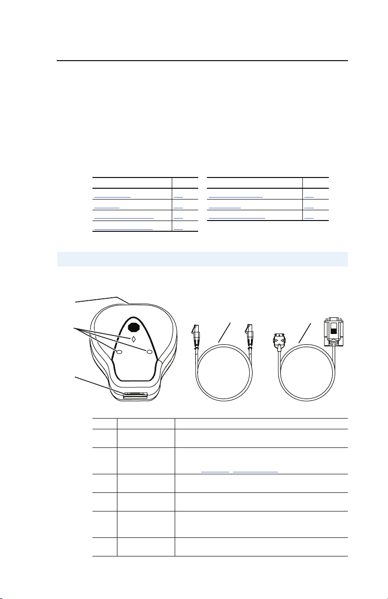
Components
Figure 1.1 Components of the Serial Converter
➊
.
Chapter 1
➋
AB
➌
# Part Description
DSI Connection Standard RJ45 connector. The 22-RJ45CBL-C20 cable is
➊
Status Indicators LEDs that indicate module operation, data is being received
➋
RS-232 Serial Port Locking low profile connector. The 1203-SFC serial cable is
➌
22-RJ45CBL-C20
➍
Cable
1203-SFC Serial
➎
Cable
Not
DriveExplorer Lite
Shown
CD-ROM
➍
plugged into this connector.
from and sent to the computer.
Refer to Chapter 5
plugged into this connector.
DSI cable (2 m) with male-to-male RJ45 connectors.
Serial cable (2 m) with a locking low profile connector to
connect to the serial converter and a 9-pin sub-miniature D
female connector to connect to a computer.
CD including DriveExplorer Lite software and
documentation.
, Troubleshooting, for more information.
➎
Page 10

1-2 Getting Started
Features
The 22-SCM-232 serial converter module features the following:
• The serial converter module can connect to products implementing
DSI such as PowerFlex 4 and 40 drives.
• Provides a means for DriveExplorer (version 3.01 or higher) and
DriveExecutive (version 1.01 or higher) software tools to access
PowerFlex 4 and 40 drives.
• Allows various Allen-Bradley controllers, from MicroLogix to
ControlLogix, to control and read/write data to PowerFlex 4 and 40
drives.
• Three status indicators (LEDs) report the operating status of the
module.
• DF1 serial baud rates of 9600 bps, 19.2 kbps, and 38.4 kbps are
supported. The factory default baud rate is 9600 bps.
• The serial converter module receives power from the DSI host
product. An outside power source is not needed.
• DriveExplorer (version 3.01 or higher), DriveExecutive (version 1.01
or higher), or terminal emulation software can be used to configure
the serial converter.
• The serial converter module is flash upgradeable to take advantage of
feature enhancements. For example, version 1.xxx SCM’s can be
flashed to version 2.xxx (or higher).
Compatible Products
The 22-SMC-232 serial converter module is compatible with
Allen-Bradley products that support DSI. At the time of publication,
compatible products include:
• PowerFlex 4 drives
• PowerFlex 40 drives
Page 11

Getting Started 1-3
Required Equipment
Equipment Shipped with the Serial Converter Module
When you unpack the serial converter module, verify that the package
includes:
❑ One 22-SCM-232 Serial Converter Module
❑ One 1203-SFC serial cable
❑ One 22-RJ45CBL-C20 cable
❑ One DriveExplorer Lite CD
❑ This manual
User-Supplied Equipment
To configure the serial converter, you must use one of the following:
❑ DriveExplorer software (version 3.01 or higher).
❑ DriveExecutive software (version 1.01 or higher).
❑ Terminal emulation software such as HyperTerminal.
❑ VT-100 compatible terminal.
Page 12

1-4 Getting Started
Safety Precautions
Please read the following safety precautions carefully.
ATTENTION: Risk of injury or equipment damage exists. Only
personnel familiar with drive and power products and the associated
!
machinery should plan or implement the installation, start-up,
configuration, and subsequent maintenance of the product using the
serial converter module. Failure to comply may result in injury and/or
equipment damage.
ATTENTION: Risk of injury or equipment damage exists. If the serial
converter module is transmitting control I/O to the drive (indicated by a
!
solid green diamond LED), the drive may fault when you remove or
reset the serial converter module. Determine how your drive will
respond before removing or resetting a connected serial converter
module.
ATTENTION: Risk of injury or equipment damage exists.
Parameter 04 - [Comm Flt Action] lets you determine the action of
!
the serial converter module and connected drive if DF1 serial
communications are disrupted. By default, this parameter faults the
drive. You can set this parameter so that the drive continues to run.
Precautions should be taken to ensure that the setting of this parameter
does not create a hazard of injury or equipment damage.
Page 13
Getting Started 1-5
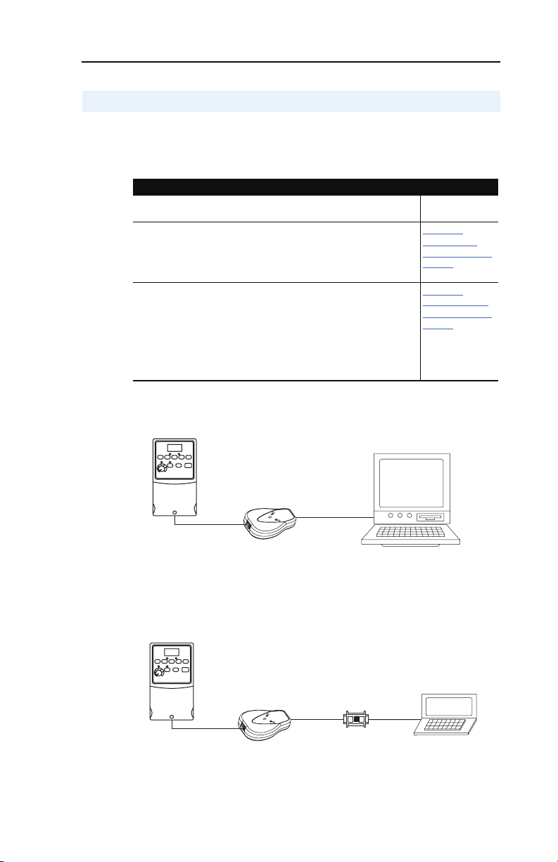
Quick Start
This section is designed to help experienced users quickly start using the
serial converter module. If you are unsure how to complete a step, refer
to the referenced chapter.
Step Action Refer to
1 Review the safety precautions for the serial converter
module.
2 Install the serial converter module.
Connect a 22-RJ45CBL-C20 cable to the serial converter
module and the DSI drive. Then, connect a 1203-SFC serial
cable to the serial conver ter module and a computer. Make
sure that power has been applied to the DSI drive.
3 Configure the serial converter module for your
application.
Use one of the following to configure parameters in the serial
converter module:
• DriveExplorer (v3.01 or higher)
• DriveTools 2000 (v1.01 or higher)
• Terminal emulation software
• VT-100 compatible terminal
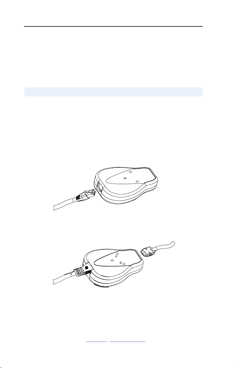
Figure 1.2 Example Serial Connection to a Personal Computer
Throughout This
Manual
,
Chapter 2
Installing the
Serial Converter
Module
Chapter
3,
Configuring the
Serial Converter
Module
22-RJ45CBL-C20
Cable
DSI Host
Serial
Converter
Figure 1.3 Example Serial Connection to a Hand-Held Computer
22-RJ45CBL-C20
Cable
DSI Host
Serial
Converter
1203-SFC
Cable
1203-SFC
Cable
(sold separately)
Computer
Serial
Cable
1203-SNM
Null Cable
Converter
Hand-Held
Computer
Page 14
1-6 Getting Started
Figure 1.4 Example Serial Connection to a Controller
22-RJ45CBL-C20
Cable
DSI Host
Serial
Converter
1203-SFC
Cable
MicroLogix
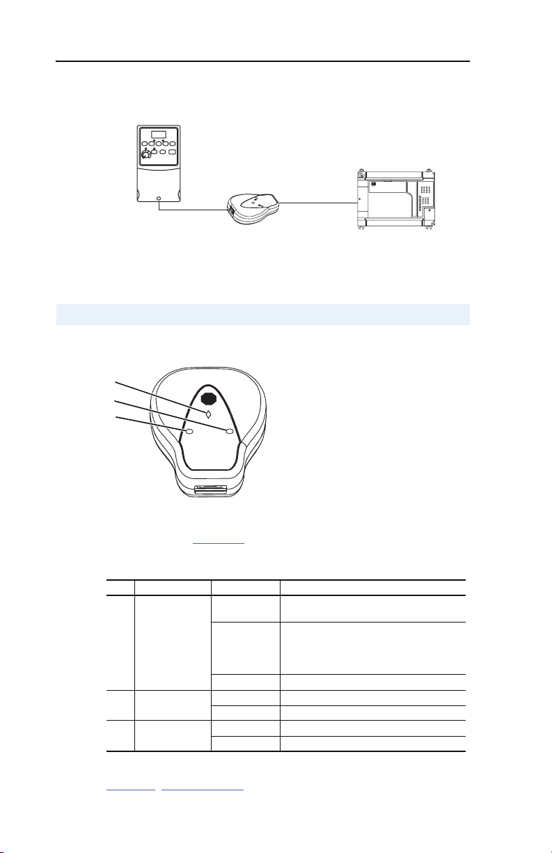
Modes of Operation
Figure 1.5 Status Indicators on the Serial Converter Module
➊
➋
AB
➌
The serial converter module uses three status indicators to report its
operating status (Figure 1.5). The following table describes the state of
the status indicators under normal operation:
# Status Indicator State Description
Diamond Flashing Green Serial converter is connected to a product
➊
Solid Green Serial converter is or was receiving control
Off No power or Flash operation in progress.
TX Off Not transmitting data.
➋
RX Off Not receiving data.
➌
Flashing Green Transmitting data.
Flashing Green Receiving data.
implementing DSI.
I/O. Removing or resetting the serial
converter may cause a serial fault in the
product.
If the diamond status indicator is red, there is a problem. Refer to
Chapter 5
, Troubleshooting.
Page 15
Chapter 2
Installing the Serial Converter
Module
Chapter 2 provides instructions for installing and removing the serial
converter module.
Topic Page
Selecting Cables
Installing the Serial Converter Module 2-2
Removing the Serial Converter Module 2-3
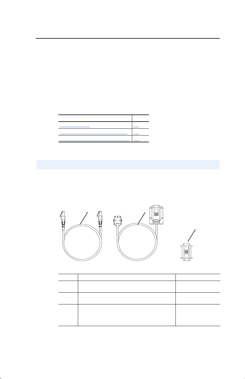
Selecting Cables
The following cables are all you should need to connect the serial
converter module to a drive and a computer.
Figure 2.1 Cables
2-1
➊
➋
➌
Number Description Catalog Number
➊
➋
➌
Important: To provide proper termination of the serial cable shield, the
DSI cable to connect the serial conver ter module to
the drive.
Serial cable to connect the serial converter module to
the computer.
When connecting the serial converter module to an
H/PC (Hand-Held PC), you must use a null modem
cable with two male 9-pin sub-miniature D
connectors. These must be purchased separately.
chassis of the computer should be properly grounded. If it is
not possible or practical to ground this, then a ground wire
22-RJ45CBL-C20
1203-SFC
1203-SNM
(sold separately)
Page 16
2-2 Installing the Serial Converter Module
should be connected to the serial cable shield at the shell of
the 9-pin sub-miniature D connector.
Important: The DSI cable shield must be properly grounded in order to
provide EMC protection. On the PowerFlex 4 and 40 drive
that means that Pin 16 of the drive control terminal block
must be connected to the drive earth ground terminal.
Installing the Serial Converter Module
Important: The module must not be installed in an area where the
ambient atmosphere contains volatile or corrosive gas,
vapors or dust. If the module is not going to be installed for
a period of time, it must be stored in an area where it will
not be exposed to a corrosive atmosphere.
1. Connect the module to the drive using the
Figure 2.2 Connecting a 22-RJ45CBL-C20 Cable to the Serial Converter
22-RJ45CBL-C20 cable.
TX
RX
2. Connect the module to the computer using the 1203-SFC cable.
Figure 2.3 Connecting a 1203-SFC Cable to the Serial Converter
3. Verify that power is applied to the DSI-enabled drive. The serial
converter module receives power from the drive, so it must be
powered before the serial converter module will operate.
The diamond light on the serial converter module flashes green to
indicate that the module is properly installed and receiving power. If it is
not green, refer to Chapter 5
, Troubleshooting.
Page 17

Installing the Serial Converter Module 2-3
Removing the Serial Converter Module
ATTENTION: Risk of injury or equipment damage exists. If the serial
converter module is transmitting control I/O to the drive (indicated by a
!
solid green diamond LED), the drive may fault when you remove or
reset the serial converter. Determine how your drive will respond before
removing or resetting a connected serial converter module.
1. Disconnect the 22-RJ45CBL-C20 cable from the DSI-enabled drive
and then from the converter module. To disconnect the cable, press
on the cable latch and then pull it out.
2. Disconnect the 1203-SFC serial cable from the serial converter
module and then the computer.
Page 18

2-4 Installing the Serial Converter Module
Notes:
Page 19

Chapter 3
Configuring the Serial Converter
Module
Chapter 3 provides instructions and information for configuring the
serial converter module.
Topic Page
Configuration Tools
Using DriveExplorer 3-2
Using Terminal Emulation Software 3-3
Setting the RS-232 Serial Port Rate 3-7
Setting the Fault Action 3-8
Resetting the Serial Converter Module 3-9
For a list of parameters, refer to Appendix B, Serial Converter Module
Parameters. For definitions of terms in this chapter, refer to the Glossary.
Configuration Tools
3-1
The serial converter module stores parameters and other information in
its own non-volatile memory. You must, therefore, access the module to
view and edit its parameters. The following tools can be used to access
the module parameters.
Tool Refer To
DriveExplorer software (version 3.01 or higher) page 3-2
DriveExecutive software (version 1.01 or higher) KWWSZZZDEFRPGULYHV
Terminal emulation software page 3-3
VT100-compatible terminal Documentation for the terminal
Important: The RS-485 serial port on DSI products, such as PowerFlex
4 and 40 drives, does not need to be configured before using
the serial converter module. DSI communications are
configured automatically (19.2K baud and 8-N-1).
in this manual
GULYHWRROVB
in this manual
Page 20
3-2 Configuring the Serial Converter Module
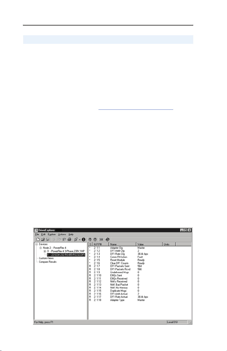
Using DriveExplorer
With DriveExplorer software, you can edit parameters in both the serial
converter module and the connected DSI-enabled drive. On PowerFlex
4/40 drives (or other DSI products), you can also edit parameters in any
of the attached peripherals. DriveExplorer Lite is shipped with the serial
converter module and is a free, limited-feature version of DriveExplorer.
Important: Parameter 1 - [Adapter Cfg] must be set to “Auto”
(default) for DriveExplorer to operate. HyperTerminal can
be used if Parameter 1 - [Adapter Cfg] needs to be
changed (see Using Terminal Emulation Software
DriveExplorer Lite Quick Start
This section is designed to help you quickly start using DriveExplorer
Lite. If you are unsure how to complete a step, refer to the online help
(select Help > Help Topics) or the DriveExplorer Getting Results
Manual, Publication 9306-5.2, which is included on the CD.
1. Select Explore > Configure Communication. Select the
communications port and baud rate that you are using. Select either
checksum, and accept the default time for the time-out.
section).
2. Select Explore > Connect > Local. A node will appear under Devices.
3. In the left pane, click the + signs to expand the tree. Click the product
or serial converter module to display parameters in the right pane.
Double-click a parameter to edit it.
Figure 3.1 DriveExplorer
Page 21
Configuring the Serial Converter Module 3-3
Using Terminal Emulation Software
This section provides detailed instructions on how to use terminal
emulation software to access the serial converter module so that you can
view and edit its parameters or view its event queue.
A variety of terminal emulation programs can be used to establish a
serial connection between a computer and the serial converter module.
The following instructions describe how to establish the initial serial
connection to the serial converter module using a computer running
HyperTerminal – terminal emulation software provided with most
Windows 95/98/NT 4.0/2000/XP operating systems.
Important: The following instructions use screen captures from
Windows 95 HyperTerminal. If you are using a different
operating system the screens may differ.
To use HyperTerminal to access the serial converter module
1. Verify that the serial converter module is installed correctly. Refer to
Chapter 2, Installing the Serial Converter Module.
2. On the Windows 95 desktop, click the Start button, and then select
Programs > Accessories > HyperTerminal to display the
HyperTerminal dialog box (see Figure 3.2
look slightly different.
). Your dialog box may
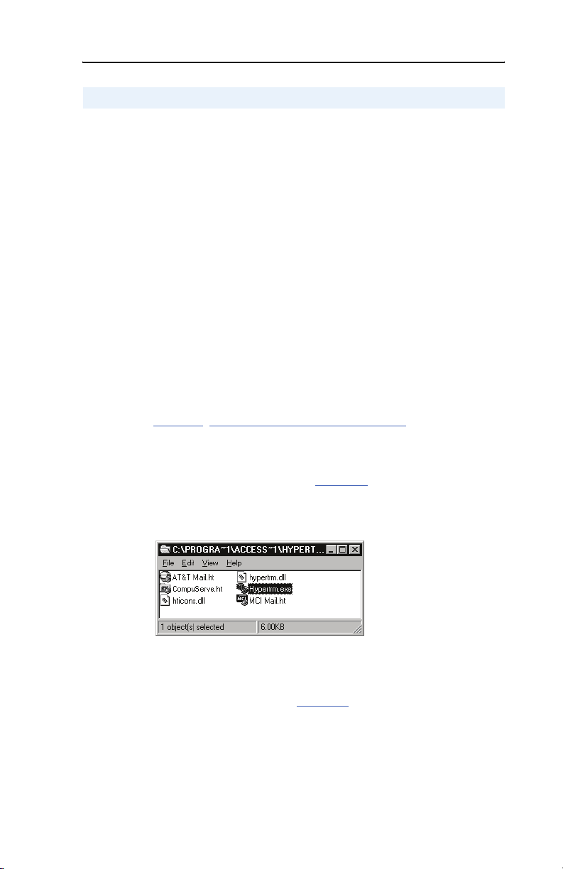
Figure 3.2 HyperTerminal Dialog Box in List View
On the Windows NT desktop, click the Start button, and then select
Programs > Accessories > HyperTerminal to display the
Connection dialog box (see Figure 3.3
3. Double-click Hypertrm.exe.
The Connection Description dialog box appears in the
HyperTerminal workspace.
). Then, go to step 4.
Page 22
3-4 Configuring the Serial Converter Module
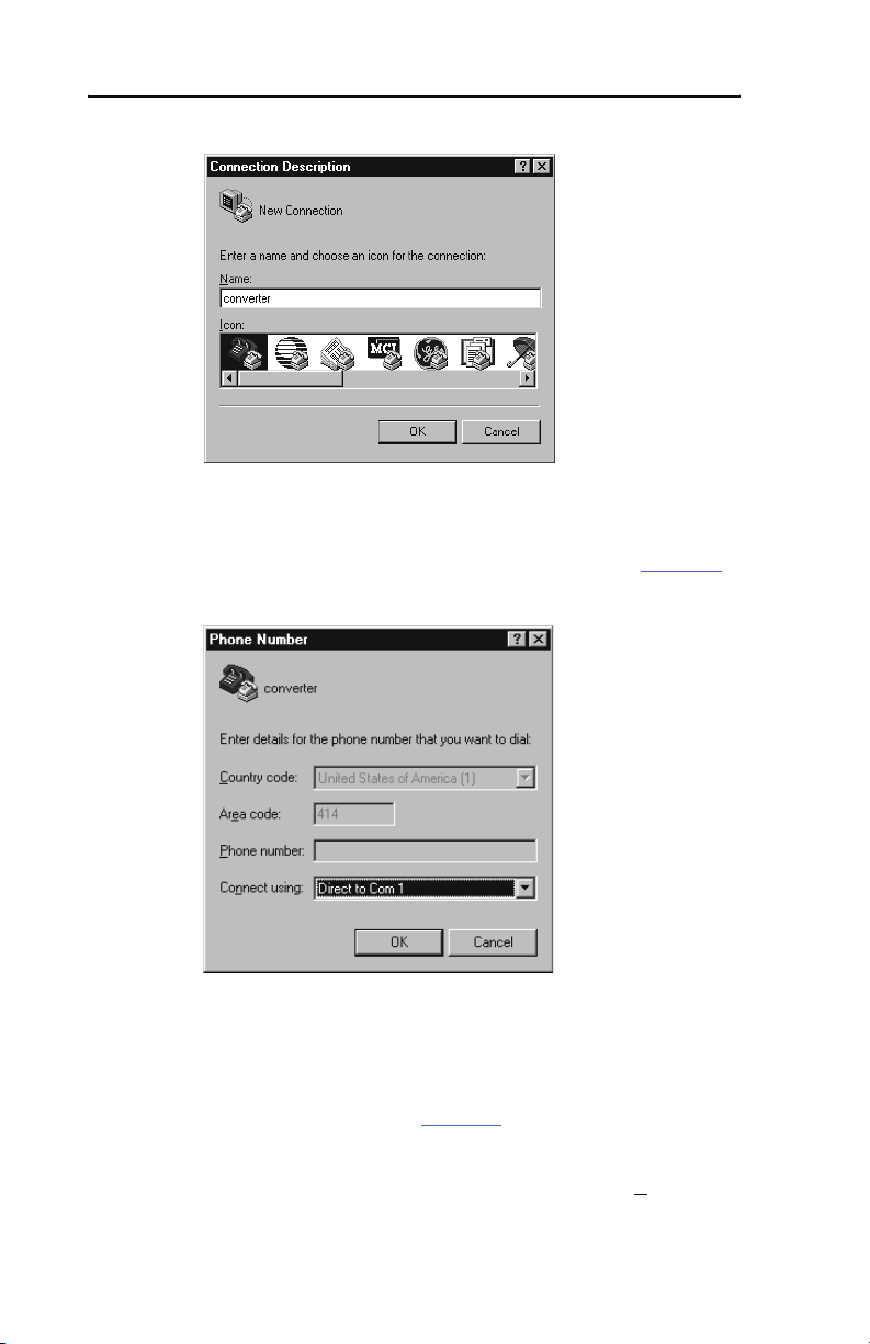
Figure 3.3 Connection Dialog Box
4. In the Name window, type any name (for example, converter), and
then select any icon in the Icon box.
5. Click OK to display the Phone Number dialog box (see Figure 3.4
Figure 3.4 Phone Number Dialog Box
6. In the Connect Using window, select the communications port that
you intend to use (usually Com1 or Com2).
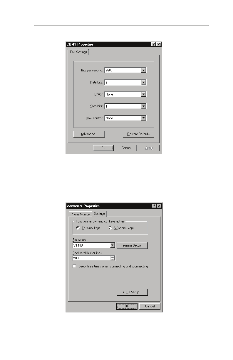
7. Click OK to display the Properties dialog box.
8. Select the settings shown in Figure 3.5
.
Important: If Parameter 03 - [DF1 Rate Cfg] was previously set
to 19.2K or 38.4K, select that value in the Bits per
second window.
).
Page 23
Configuring the Serial Converter Module 3-5
Figure 3.5 Properties Dialog Box
9. Click OK. A blank HyperTerminal workspace appears.
10. Select File > Properties to display the Properties dialog box.
11. Click the Settings tab (see Figure 3.6
Figure 3.6 Properties Dialog Box
).
12. Under Function, arrow, and ctrl keys act as, select Termi n a l keys .
Page 24
3-6 Configuring the Serial Converter Module
13. In the Emulation window, select VT100.
14. Click OK to display the HyperTerminal workspace.
TIP: Select File > Save to save the HyperTerminal configuration that
you just created. In future connections, you can select the saved
configuration and quickly connect to the serial converter module.
15. Press the Enter key until the main menu appears (see Figure 3.7).
Figure 3.7 Main Menu
Main Menu - Enter Number for Selection
1> Display Setup Parameters
2> Display Event Queue
3> Flash Upgrade
What do you want to do? Page
Edit the serial port rate, or fault action 3-7
View the event queue 5-3
View DF1 data 5-5
Update the firmware C-1
If no text or meaningless text appears instead of the Main Menu,
adjust the baud rate in your software. Refer to Chapter
Troubleshooting Potential Problems section for detailed instructions.
through 3-9
5 in the
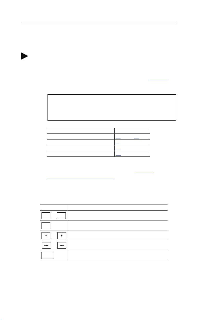
To navigate in the terminal emulation software
Key Description
0
Esc
Enter
.. .
OR
OR
In the main menu, keys 1 – 3 select a menu option.
9
In the parameter screen, keys 0 – 9 enter a value.
Display the main menu or abort changes to a parameter.
Scroll through parameters or events.
Scroll through the values for a parameter.
Save a value for a parameter.
Page 25

Configuring the Serial Converter Module 3-7
Setting the RS-232 Serial Port Rate
The serial port rate, sometimes called baud rate or DF1 rate, is the speed
at which the computer and serial converter module communicate over
RS-232. You can select a serial port rate of 9600, 19.2K, or 38.4K. The
factory-default serial port rate is 9600.
Important: If you change the serial port rate in the serial converter
module, you must set your software to use the same serial
port rate. The serial converter module must be reset or
power cycled before baud rate changes take affect.
To set the serial port rate
1. Set Parameter 03 - [DF1 Rate Cfg] to the desired rate.
Figure 3.8 DF1 Rate Cfg Parameter in HyperTerminal
Press the UP ARROW or DOWN ARROW key to scroll
through the parameter list. Press the LEFT ARROW
or RIGHT ARROW key to modify parameter values.
Press the ENTER key to save a new value.
3> DF1 Rate Cfg = 9600
2. Reset the serial converter module. Refer to Resetting the Serial
Converter Module section in this chapter.
3. Set the serial port rate in your software to match the new serial port
rate in the serial converter module.
Page 26

3-8 Configuring the Serial Converter Module
Setting the Fault Action
By default, when DF1 serial communications are disrupted (for example,
a serial cable is disconnected) and control I/O is being transmitted, the
serial converter module and connected drive respond by faulting. You
can set a different response to communication disruptions using
Parameter 04 - [Comm Flt Action].
ATTENTION: Risk of injury or equipment damage exists.
Parameter 04 - [Comm Flt Action] lets you determine the action of
!
the serial converter module and connected drive if communications are
disrupted. By default, this parameter faults the drive. You can set this
parameter so that the drive continues to run. Precautions should be
taken to ensure that the setting of this parameter does not create a
hazard of injury or equipment damage.
To change the fault action
• Set the value of Parameter 04 - [Comm Flt Action] to the desired
response:
Action Description
Fault The drive is faulted and stopped. (Default)
Stop The drive is stopped, but not faulted (DSI host products only).
Zero data The drive is sent 0 for output data after a communications disruption.
Hold last The drive continues in its present state after a communications
This does not command a stop.
disruption.
Figure 3.9 Comm Flt Action Parameter in HyperTerminal
Press the UP ARROW or DOWN ARROW key to scroll
through the parameter list. Press the LEFT ARROW or
RIGHT ARROW key to modify parameter values. Press
the ENTER key to save a new value.
4> Comm Flt Action = Fault
Changes to this parameter take effect immediately. A reset is not
required.
Page 27

Configuring the Serial Converter Module 3-9
Resetting the Serial Converter Module
Change to settings on some module parameters require that you reset the
serial converter module before the new settings take effect. You can reset
the module by cycling power to the module or by using Parameter 05 -
[Reset Module].
ATTENTION: Risk of injury or equipment damage exists. If the serial
converter module is transmitting control I/O to the drive (indicated by a
!
solid green diamond LED), the drive may fault when you remove or
reset the module. Determine how your drive will respond before
removing or resetting a connected serial converter module.
To reset the serial converter
• Set Parameter 05 - [Reset Module] to either Reset Module or Set
Defaults. “Reset Module” will reset the serial converter. “Set
Defaults” will set all parameters in the serial converter to their
factory-default values.
Figure 3.10 Reset Module Parameter in HyperTerminal
Press the UP ARROW or DOWN ARROW key to scroll
through the parameter list. Press the LEFT ARROW
or RIGHT ARROW key to modify parameter values.
Press the ENTER key to save a new value.
5> Reset Module = Reset Module
After you enter the “Reset Module” value, the serial converter will be
reset. This parameter will then be reset to “Ready.”
Page 28

3-10 Configuring the Serial Converter Module
Notes:
Page 29

Chapter 4
Controlling PowerFlex 4 and 40
Drives with Allen-Bradley Controllers
Chapter 4 illustrates how to use the 22-SCM-232 serial converter with
Allen-Bradley controllers to control and read/write data to PowerFlex 4
and 40 drives.
Topic Page
Controller Compatibility
Cabling Requirements 4-2
Messaging (MSG Instruction) 4-3
PowerFlex 4 and 40 Memory Addressing 4-4
Example Controller Programs 4-4
Controller Compatibility
Any Allen-Bradley controller capable of initiating and receiving DF1
messages can be used with the 22-SCM-232 serial converter:
4-1
• MicroLogix 1000 (Series C or later discrete controllers, and all
analog controllers)
• MicroLogix 1200/1500
• SLC 5/03, 5/04, 5/05
• PLC5
• ControlLogix/CompactLogix
The 22-SCM-232 converts the protocol from DF1 to Modbus RTU, and
the media from RS232 to RS485. It can be used for point-to-point and
multiple drive applications (see Figure 4.1
Important: DSI HIMs (22-HIM-*) and/or DSI communication adapters
(22-COMM-*) cannot be used in an Allen-Bradley
controller/22-SCM-232 system.
and Figure 4.2 respectively).
Page 30
4-2 Controlling PowerFlex 4 and 40 Drives with Allen-Bradley Controllers
A
B
A
B
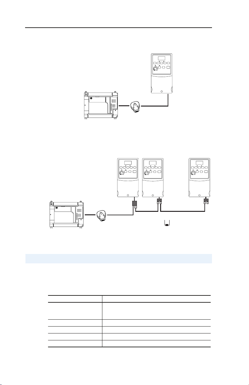
Figure 4.1 Point-to-Point Example
Drive
Controller
RS232
DF1
RS485
Modbus RTU
22-SCM-232
Serial Converter
Figure 4.2 Multiple Drive Example
Drive # 1
Drive # 2
Drive # 31
Controller
RS232
DF1
22-SCM-232
Serial Converter
RS485
Modbus RTU
AK-U0-RJ45-SC1
Splitter Cable
AK-U0-RJ45-TB2P
Ter minal Blocks
1/4W, 120 Ω
Ter minating Resistors
(on first and last drives)
Cabling Requirements
In addition to using the 22-SCM-232 serial converter module, the
required cabling depends on the type of Allen-Bradley controller being
used:
Controller Type Requires 22-SCM-232 plus …
MicroLogix 1000/1200/1500
LSP
1761-CBL-PM02 or 1761-CBL-AP00 (8-pin DIN to 9-pin
Female) and 1203-SNM Serial Null Modem adapter (9-pin
Male to 9-pin Male)
MicroLogix 1500 LRP —
SLC 5/03, 5/04 or 5/05 —
PLC5 9-pin Male to 25-pin Male adapter (3rd party)
ControlLogix/CompactLogix —
Page 31

Controlling PowerFlex 4 and 40 Drives with Allen-Bradley Controllers 4-3
Messaging (MSG Instruction)
Communications are handled via Message (MSG) instructions, which
vary between the different controllers.
Figure 4.3 MicroLogix 1200/1500 MSG Setup Screen Example
The following descriptions are for the user configurable items of the
MSG instruction.
MSG User Configurable Item Description
Channel Channel # to which the 22-SCM-232 is connected
Communication Command Message type used
Data Table Address Source of write data/destination of read data
Size in Elements Number of words to read/write (32 max.)
Message Timeout Number of seconds before the message times out
Data Table Address Memory address in PowerFlex 4/40 to be accessed
Local Node Addr (dec) PowerFlex 4/40 node address (decimal)
Local Node Addr (octal) PowerFlex 4/40 node address (octal)
Local/Remote Type of communication used
For additional information on MSG instruction setups, refer to the
respective controller instruction set reference manuals:
Publication Name Publication Number
MicroLogix 1000 1761-6.3
MicroLogix 1200/1500 Instruction Set Reference Manual 1762-RM001…
SLC 1747-RM001…
PLC5 1785-6.1
ControlLogix Manual 1756-RM003…
CompactLogix Manual 1769-UM007…
Page 32

4-4 Controlling PowerFlex 4 and 40 Drives with Allen-Bradley Controllers
PowerFlex 4 and 40 Memory Addressing
PowerFlex 4 and 40 control and status information, and parameters are
addressed using N: file addressing.
Logic Command/Reference
Control Data Address
Logic Command N182:192
Reference N182:193
Logic Status/Feedback/Additional Monitor Data
Monitor Data Address
Logic Status N183:198
Drive Error Code N183:199
Frequency Command N183:200
Output Frequency (Feedback) N183:201
Output Current N183:202
DC Bus Voltage N183:203
Output Voltage N183:204
Step # of Multi-Step Speed Operation N183:205
Step # of PLC Operation N183:206
Time of PLC Operation N183:207
Counter Value N183:208
The Logic Command and Logic Status bit definitions are described in
Appendix I.
Parameters
PowerFlex 4 and 40 parameters are addressed using Integer File N150:x,
where “x” equals the actual parameter number in the drive. For example:
N150:39 = Parameter 39 - [Accel Time 1]
Example Controller Programs
Example ladder logic programs are provided for each type of controller
platform. Refer to the appropriate appendix:
Controller Type Example Ladder Logic Program
• MicroLogix 1000 See Appendix D
• MicroLogix 1200/1500 See Appendix E
• SLC See Appendix F
• PLC See Appendix G
• ControlLogix/CompactLogix See Appendix H
Page 33

Chapter 5
Troubleshooting
Chapter 5 provides information for troubleshooting potential problems
with the serial converter module.
Topic Page
Understanding the Status Indicators
Module Diagnostic Items 5-3
Viewing and Clearing the Event Queue 5-3
Viewing and Clearing DF1 Communication Statistics 5-5
Troubleshooting Potential Problems 5-6
Understanding the Status Indicators
The serial converter module has three status indicators to reports its
operating status. See Figure 5.1
Figure 5.1 Status Indicators on the Serial Converter
.
5-1
➊
➋
AB
➌
# Status Indicator Description Refer To
Diamond Serial converter status Diamond Status Indicator
➊
TX Serial converter is transmitting
➋
RX Serial converter is receiving
➌
data
data
on page 5-2
TX Status Indicator on
page 5-2
RX Status Indicator on
page 5-2
Page 34

5-2 Troubleshooting
Diamond Status Indicator
ATTENTION: Risk of injury or equipment damage exists. If the serial
converter module is transmitting control I/O to the drive (indicated by a
!
solid green diamond LED), the drive may fault when you remove or
reset the module. Determine how your drive will respond before
removing or resetting a serial converter module.
Status Cause Corrective Action
Off Serial converter module
is not powered or in Flash
programming mode.
Flashing
Serial converter module
Green
is operating and not
transmitting control I/O.
Solid
Serial converter module
Green
is operating and is or was
transmitting control I/O.
Flashing
The drive has not
Red
acknowledged the serial
converter module.
Solid
Link failure. • Securely connect cables.
Red
Orange Contact Rockwell Automation Technical Support.
• Securely connect cables.
• Apply power to the drive.
• Wait while Flash is in progress.
No action. Removing or resetting the serial
converter module will not cause a serial fault in the
drive.
No action. Removing or resetting the serial
converter will cause a serial fault in the drive.
• Securely connect cables.
• Verify Parameter 1 - [Adapter Cfg] is set to
“Auto.”
• Replace the cable.
• Cycle power to the drive.
RX Status Indicator
Status Cause Corrective Action
Off Serial converter module
is not receiving data.
Flashing
Serial converter module
Green
is receiving data from the
computer.
• Verify that data is being transmitted by the PC.
• Securely connect cables.
• Apply power to the drive.
• Configure the computer software to use the
same serial port rate as the converter module.
No action.
TX Status Indicator
Status Cause Corrective Action
Off Serial converter module
is not transmitting data.
Flashing
Serial converter module
Green
is transmitting data to the
computer.
• Verify that data is being transmitted.
• Securely connect cables.
• Apply power to the drive.
No action.
Page 35

Troubleshooting 5-3
Module Diagnostic Items
The following diagnostic items can be accessed using DriveExplorer
(version 3.01 or higher).
No. Name Description
1 Field Flash Cnt Number of times the module has been Field Flashed.
2 Adapter Events The number of events in the event queue.
3 Reference Current value of the Reference being transmitted to the
4 Logic Command Current value of the Logic Command being transmitted to
5 Logic Status Current value of the Logic Status being received from the
6 Feedback Current value of the Feedback being received from the
drive by this module.
the drive by this module.
drive by this module.
drive by this module.
Viewing and Clearing the Event Queue
The serial converter module has an event queue that reports the history
of its actions.
To view the event queue
1. Access the event queue using a configuration tool. Refer to the
Configuration Tools section in Chapter 3.
2. Scroll through events in the event queue. The most recent event can
be found at 2R > Event Queue 1. The “R” stands for Read Only.
Figure 5.2 Example Event Queue in HyperTerminal
Press the UP ARROW or DOWN ARROW key to scroll
through the parameter list. Press the LEFT ARROW or
RIGHT ARROW key to modify parameter values. Press
the ENTER key to save a new value.
2R> Event Queue 1 = Normal Startup
Page 36

5-4 Troubleshooting
Events
Many events in the Event queue occur under normal operation. If you
encounter unexpected communications problems, the events may help
you or Allen-Bradley personnel troubleshoot the problem. The following
events may appear in the event queue:
Code Event Description
F0 No Event No event present in the module event queue.
F1 Adapter Reset The module was reset by the user.
F2 Slave Detected Slave was detected to be present by master.
F3 Slave Removed Slave was detected to be removed by master.
F4 Host Timeout Timeout condition on Msg to Host.
F5 Slave Timeout Timeout condition on Msg to Slave.
F6 Master Timeout Timeout condition on Msg to Master.
F7 Serial Timeout Timeout on Serial 232 side (w/control enabled).
F8 Control Enabled The module has sent a “Soft Control Enable” command
F9 Control Disabled The module has sent a “Soft Control Disable”
F10 EEPROM Sum Flt Startup sequence detected corrupt EEPROM storage
To clear the event queue
to the drive.
command to the drive.
in the module.
1. Access the event queue using a configuration tool. Refer to the
Configuration Tools section in Chapter 3.
2. Set the value of 1 > Clr Event Queue to Enable, and then press
Enter to clear the event queue.
Figure 5.3 Reset Event Queue in HyperTerminal
Press the UP ARROW or DOWN ARROW key to scroll
through the parameter list. Press the LEFT ARROW or
RIGHT ARROW key to modify parameter values. Press
the ENTER key to save a new value.
1> Clr Event Queue = Enable
Page 37

Troubleshooting 5-5
Viewing and Clearing DF1 Communication Statistics
If you encounter unexpected communications problems or are creating
an application that uses DF1 data, you can view the communications
statistics in the serial converter module. Parameters 06 through 17 store
this data.
To view and clear DF1 data, you must access the main menu in the serial
converter module firmware. Refer to the Configuration Tools section in
Chapter 3
To view DF1 data
1. Access the parameters in the serial converter using a configuration
2. Scroll through the DF1 parameters. Parameters 06 through 17
Figure 5.4 Example Parameter Display in HyperTermina
l
Press the UP ARROW or DOWN ARROW key to scroll
through the parameter list. Press the LEFT ARROW or
RIGHT ARROW key to modify parameter values. Press
the ENTER key to save a new value.
.
tool. Refer to the Configuration Tools section in Chapter 3.
contain DF1 data. For a description of each parameter, refer to
Appendix B
, Serial Converter Module Parameters.
7R> DF1 Packets Sent = 0
To clear DF1 counters
1. Access the parameters in the serial converter using a configuration
tool. Refer to the Configuration Tools section in Chapter 3.
2. Set the value of Parameter 06 - [Clear DF1 Counts] to Clear
Counts, and then press Enter to clear the DF1 data.
Figure 5.5 Example Parameter Display in HyperTerminal
Press the UP ARROW or DOWN ARROW key to scroll
through the parameter list. Press the LEFT ARROW or
RIGHT ARROW key to modify parameter values. Press
the ENTER key to save a new value.
6> Clear DF1 Counts = Clear Counts
Page 38

5-6 Troubleshooting
Troubleshooting Potential Problems
Description Action
You are unable to establish a
connection between your computer
and the serial converter module.
After changing the serial port rate,
you are no longer able to
communicate with the serial
converter module and connected
drive.
For example, in HyperTerminal,
meaningless text appears on the
screen when you press Enter. In
DriveExplorer, parameter values are
not updated.
You set a new serial port rate, but the
serial converter module is still using
the old serial port rate.
No communications to the drive. • Verify cable connections.
• If the status indicators are off, connect the
cables and apply power to the drive.
• Configure your software and serial converter
module to use the same COMM port and serial
port rate (baud rate).
Reset the serial por t rate in the software.
Instructions are included here to reset the serial
port rate in HyperTerminal and DriveExplorer. If
you are using a different configuration tool, refer
to its user manual.
HyperTerminal
1. Select File > Properties, and then click
Configure.
2. Select the new baud rate, and then click OK.
3. Save and close HyperTerminal.
4. Double-click on your HyperTerminal file (*.ht)
to restart HyperTerminal.
5. Press Enter until the main menu appears.
DriveExplorer
1. Select Explore > Configure Communication.
2. Select the new baud rate. DriveExplorer
should start updating values again. If it does
not, restart DriveExplorer.
Reset the serial conveter module. Refer to
Chapter 3
, Configuring the Serial Converter
Module.
• Make sure Parameter 1 - [Adapter Cfg] is set
to “Auto.”
Page 39

Appendix A
Specifications
Appendix A presents the specifications for the serial converter module.
Topic Page Topic Page
Communications
Electrical A-1 Agency Certification A-2
Mechanical A-1
Communications
RS-232 side
Protocol
Port Rate
Data Bits
Parity
Stop Bits
Flow Control
Error
DSI Host side
Protocol
Data Rates
A-1 Environmental A-2
RS-232 Serial DF1, Full Duplex
9600, 19.2K, or 38.4K
8
None
1
None
CRC or BCC (Auto-Detected)
Drive Serial Interface (DSI)
19.2K
Electrical
Consumption 170mA at + 5V DC
The serial converter draws the required power
from the connected product. An external power
source is not required.
Mechanical
Dimensions
Height
Width
Depth
Weight 70.88 g (2.5 oz.)
103.5 mm (4.08 inches)
73.4 mm (2.89 inches)
23.6 mm (0.93 inches)
Page 40

A-2 Specifications
Environmental
Temperature
Operating
Storage
Relative Humidity 5 to 95% non-condensing
Atmosphere Important: Serial converter module must not be
Vibration
Operating
Non-Operating
Shock
Operating
Non-Operating
Agency Certification
0 to +50° C (32 to 122° F)
-40 to +85° C (-40 to 185° F)
installed in an area where the ambient
atmosphere contains volatile or corrosive gas,
vapors or dust. If the module is not going to be
installed for a period of time, it must be stored in
an area where it will not be exposed to a corrosive
atmosphere.
2.5G @5Hz-2KHz
5G @5Hz-2KHz
30 G peak acceleration, 11 (±1) ms pulse width
50 G peak acceleration, 11 (±1) ms pulse width
UL
cUL
CE
CTick AS/NZS 2064, Group 1, Class A
UL508C
CAN/CSA C22.2 No. 14-M91
EN50178 and EN61800-3
Important: For this product to be CE and CTick compliant, the shield
of the serial cable and DSI cable must be terminated as
described on Page 2-2
.
Page 41

Serial Converter Module Parameters
Appendix B provides information about the serial converter module
parameters.
Parameter List
No. Name and Description Details
01 [Adapter Cfg]
Sets the operation of the serial converter module on
DSI. Leave at “Auto” (setting) when used with software
tools.
Important: Parameter 1 - [Adapter Cfg] must be set to
“Auto” (default) for DriveExplorer to operate.
HyperTerminal can be used if Parameter 1 - [Adapter
Cfg] needs to be changed (See Using Terminal
Emulation Software).
02 [DF1 Addr Cfg]
Sets the DF1 node address for the serial converter
module. This is a decimal value.
03 [DF1 Rate Cfg]
Sets the serial port rate for the RS-232 DF1 serial port
on the serial converter module.
Important: If you change the serial port rate in the
serial converter module, you must set your software to
use the same serial port rate. The serial converter
module must be reset or power cycled before baud
rate changes take affect.
04 [Comm Flt Action]
Sets the action that the serial convertermodule and
drive take if the module detects that DF1 serial
communications are disrupted. This setting is effective
only if I/O that controls the drive is transmitted through
the serial converter module.
Default: 0 = Auto
Values: 0 = Auto
Type: Read/Write
Reset Required:
Default: 1
Minimum: 0
Maximum: 254
Type: Read/Write
Reset Required: Yes
Default: 0 = 9600
Values: 0 = 9600
Type: Read/Write
Reset Required: Yes
Default: 0 = Fault
Values: 0 = Fault
Type: Read/Write
Reset Required: No
Appendix B
1 = Master
2 = Slave
3 = RTU Master
4 = RTU Passthru
1 = 19.2K
2 = 38.4K
1 = Stop
2 = Zero Data
3 = Hold Last
ATTENTION: Risk of injury or equipment damage exists. Parameter 04 -
[Comm Flt Action] lets you determine the action of the serial converter
module and connected drive if communications are disrupted. By default,
!
this parameter faults the drive. You can set this parameter so that the drive
continues to run. Precautions should be taken to ensure that the setting of
this parameter does not create a hazard of injury or equipment damage.
Page 42

B-2 Serial Converter Module Parameters
No. Name and Description Details
05 [Reset Module]
No action if set to “Ready.” Resets the serial converter
module if set to “Reset Module.” Restores the module
to its factory-default settings if set to “Set Defaults.”
This parameter is a command. It will be reset to “0 =
Ready” after the command has been performed.
ATTENTION: Risk of injury or equipment damage exists. If the serial
converter module is transmitting I/O that controls the drive (indicated by a
solid green diamond LED), the drive may fault when you remove or reset the
!
module. Determine how your drive will respond before removing or resetting
a connected serial converter module.
06 [Clear DF1 Counts]
No action if set to “Ready.” Resets the DF1 statistical
parameters (numbers 07 – 15) to 0 if set to “Clear
Counts.” This parameter is a command. It will be reset
to “0 = Ready” after the command has been
performed.
07 [DF1 Packets Sent]
Displays the number of DF1 packets sent by the serial
converter module. The value of this parameter is
normally approximately equal to the value of
Parameter 08 - [DF1 Packets Rcvd].
08 [DF1 Packets Rcvd]
Displays the number of DF1 packets received by the
serial converter module. The value of this parameter is
normally approximately equal to the value of
Parameter 07 - [DF1 Packets Sent].
09 [Undelivered Msgs]
Displays the number of DF1 messages that were sent
but not acknowledged.
10 [ENQs Sent]
Displays the number of ENQ characters sent by the
serial converter module.
11 [ENQs Received]
Displays the number of ENQ characters received by
the serial converter module.
12 [NAKs Received]
Displays the number of NAK characters received by
the serial converter module.
13 [NAK Bad Packet]
Displays the number of NAKs sent by the serial
converter module because of corrupt packets
(improper protocol messages) as determined by the
module.
(1)
This value is normally a low value. If it is continually incrementing and you are having
communications problems, use a lower baud rate or replace the 1203-SFC serial cable.
(1)
(1)
(1)
(1)
(1)
Default: 0 = Ready
Values: 0 = Ready
Type: Read/Write
Default: 0 = Ready
Values: 0 = Ready
Type: Read/Write
Reset Required: No
Default: 0
Minimum: 0
Maximum: 4294967295
Type: Read Only
Default: 0
Minimum: 0
Maximum: 4294967295
Type: Read Only
Default: 0
Minimum: 0
Maximum: 65535
Type: Read Only
Default: 0
Minimum: 0
Maximum: 65535
Type: Read Only
Default: 0
Minimum: 0
Maximum: 65535
Type: Read Only
Default: 0
Minimum: 0
Maximum: 65535
Type: Read Only
Default: 0
Minimum: 0
Maximum: 65535
Type: Read Only
1 = Reset Module
2 = Set Defaults
1 = Clear Counts
Page 43

Serial Converter Module Parameters B-3
No. Name and Description Details
14 [NAK No Memory]
Displays the number of NAKs sent by the serial
converter module because it did not have sufficient
memory to buffer the incoming messages. The module
runs out of memory if a command has not completed
and there is no place to save the new commands.
15 [Duplicate Msgs]
Displays the number of duplicate messages sent to the
serial converter module. This value contains the total
number of consecutive messages received by the
module with the same TNS (Transaction Sequence)
number.
16 [DF1 Addr Actual]
Displays the DF1 address actually used by the serial
converter module.
17 [DF1 Rate Actual]
Displays the serial port rate actually used for the DF1
serial port on the serial converter module.
(1)
(1)
Default: 0
Minimum: 0
Maximum: 65535
Type: Read Only
Default: 0
Minimum: 0
Maximum: 65535
Type: Read Only
Default: 1
Minimum: 0
Maximum: 254
Type: Read Only
Default: 0 = 9600
Values: 0 = 9600
Type: Read Only
18 [Adapter Type]
Displays the present operating mode for the serial
converter module.
Default: 0 = Master
Values: 0 = Master
Type: Read Only
(1)
This value is normally a low value. If it is continually incrementing and you are having
communications problems, use a lower baud rate or replace the 1203-SFC serial cable.
1 = 19.2K
2 = 38.4K
1 = Slave
2 = RTU Master
3 = RTU Passthru
Page 44

B-4 Serial Converter Module Parameters
Notes:
Page 45

Appendix C
Flash Updates
Appendix C provides information on updating peripheral product
firmware.
Topic Page
Preparing for a Flash Update
Performing a Flash Update with
HyperTerminal
Troubleshooting Potential HyperTerminal
Flash Problems
Preparing for a Flash Update
Please take the following precautions to ensure a successful Flash:
• Obtain the new firmware version from Rockwell Automation, Inc.
Save it to the hard drive of the computer. Do not attempt to perform a
Flash from a floppy disk or a network.
C-1
C-2
C-3
• Read all instructions supplied with the new firmware file.
• Use a computer running terminal emulation software that supports
Xmodem transfers (e.g. HyperTerminal). In this manual, we show
how to use HyperTerminal.
• Record parameter values in the device that will be flashed. Updates
may reset parameters to their default settings.
• Ensure that the DSI-enabled drive (e.g. PowerFlex 4) is stopped.
• Close all programs except the terminal emulation program that you
are using to Flash the serial converter module.
• If you are using a laptop computer, turn off the FIFO buffers in
HyperTerminal. In HyperTerminal, select File > Properties to
display the Properties dialog box. Click Configure, and then click
Advanced. Ensure that a check mark does not appear next to Use
FIFO buffers.
Page 46

C-2 Flash Updates
Performing a Flash Update with HyperTerminal
1. In the main menu (Figure 3.7
The screen in Figure C.1 will immediately appear.
Figure C.1 Flash Menu
To update the Flash memory, you need a terminal
program capable of downloading a binary file using
the XMODEM protocol and a Flash update file from
Rockwell Automation. When you press 'Y' to signal
that you are ready to proceed, the terminal
program will start displaying the letter 'C'. This
signals the XMODEM protocol that the download may
proceed. You then have one minute to start the
transfer. Press CTRL-X to cancel an update started
by mistake. Are you ready to proceed? (Y/N)
ATTENTION: Risk of injury or equipment damage
exists. When you perform a Flash update, the drive will
!
fault if it is receiving control I/O from the serial converter
module. Verify that the drive has stopped safely or is
receiving control I/O from an alternate source before
beginning a Flash update.
ATTENTION: Risk of equipment damage exists. If you
interrupt a flash procedure that is updating boot code, the
!
device may become inoperable. To prevent this damage,
follow the instructions provided with the new firmware
file and do not interrupt a flash procedure while boot
code is being flashed.
), press 3 to Update Flash program.
2. If the Flash can be completed safely, type Y. The letter “C”
repeatedly appears. It is the Xmodem prompt and continues to
appear until you send a binary file.
Important: Press Ctrl + X to cancel a Flash update procedure.
3. Select Transfer > Send File to display the send file dialog box.
4. Click Browse and navigate to the Flash file.
5. Double-click the file. Its name appears in the Filename box (see
Figure C.2
).
Page 47

Flash Updates C-3
6. In the Protocol box, select Xmodem.
Figure C.2 Example Send File Dialog Box
7. Click Send. A dialog box appears and reports the progress of the
download. When it is complete, the message “Operation Complete”
appears.
Important: Keep the device powered for 15 seconds after the
operation has completed.
8. Press the Enter key to return to the main menu.
Troubleshooting Potential HyperTerminal Flash
Problems
Description Corrective Action
“Transfer Cancelled by Remote
System” message appears and the
Flash is not completed.
The “Xmodem File Send” for dialog
box appears, but the Flash file is not
transferred.
After completing a Flash, you are
unable to communicate with the serial
converter module. For example,
meaningless text appears on the
HyperTerminal screen.
• Restart HyperTerminal and repeat the Flash
procedure.
• If you are using Windows NT 4.0, install SP3
or later. Windows NT service packs are
available from the Microsoft web site:
http://www.microsoft.com.
• Download a HyperTerminal Private Edition
update from the Hilgraeve web site:
http://www.hilgraeve.com.
(Please note that there is a license
requirement with this software.) Then, perform
the Flash procedure again.
• Verify that you have selected the Xmodem
protocol in the Send file dialog box.
• Verify that the new file is on your hard disk. Do
not attempt to Flash from a floppy disk or a
network.
• Verify that you are sending the file within 60
seconds of pressing “Y” to confirm that you
want to perform the Flash.
Set the serial port rate to 9600. If parameters are
changed during a Flash update, all parameters
are set to their default settings.
Page 48

C-4 Flash Updates
Performing a Flash Update with DriveExplorer
DriveExplorer version 4.xx and higher can perform flash updates on DSI
products that use flash memory, such as the 22-SCM-232 Serial
Converter Module and 22-COMM-D DeviceNet adapter. A 22-SCM-232
(version 2.01 or higher) is required to perform the update.
DriveExplorer utilizes the same files used by ControlFlash, which can be
downloaded from www.ab.com/drives.
The following steps illustrate how to flash update a 22-SCM-232, and
can be applied to flashing other DSI products.
1. Connect the 22-SCM-232 using DriveExplorer, and select “Explore |
Device Properties …” Click on the Details tab to display the
information about the 22-SCM-232. Click on the F
button.
lash Update
2. Select the revision of firmware that you wish to update to, and click
on the Next> button.
Page 49

Flash Updates C-5
3. Confirm that this is what you want to do by clicking the FLASH button.
4. The following dialog boxes will display information about the
progress of the flash.
Page 50

C-6 Flash Updates
5. When the flash is completed, the “FLASH” button changes to
“Close” and the “Cancel” button is grayed out.
6. DriveExplorer will prompt you to reconnect since the device may
have changed its database because of the flash. Click “Yes” to
reconnect.
Page 51

Appendix D
MicroLogix 1000 Example Ladder
Program
Appendix D provides information on a MicroLogix 1000 example ladder
program. The following ladder example demonstrates:
• Writing Logic Command and Reference
• Reading Logic Status, Feedback, and additional monitor data
• Writing/reading Parameter 39 - [Accel Time 1]
Page 52

D-2 MicroLogix 1000 Example Ladder Program
Figure D.1 Example MicroLogix 1000 Ladder Logic Program
Connection:
The 22-SCM-232 connects to the front port on the MicroLogix 1000 by using a 1203-SNM Null Modem
adapter and a 1761-CBL-AP00 programming cable. The RJ45 cable on the 22-SCM-232 conencts to the
RJ45 port on the PowerFlex 4/40. The SCM provides both media (RS232 to RS485) and protocol (DF1 to
Modbus RTU) conversions.
Additional PF4/40 drives can be added. Use one AK-U0-RJ45-SC1 Splitter Cable for connecting to the
first drive, and one AK-U0-RJ45-TB2P for every drive. The "Local Node Address" in the MSG instruction
indentifies the drive node to communicate with.
PF4 Parameters: 22-SCM-232 parameters:
36 [Start Source] = 5 (Comm Port) 1[Adapter Cfg] = RTU Master
38 [Speed Reference] = 5 (Comm Port) 2[DF1 Addr Cfg] = 1 (this MUST equal Parameter 104 of the PF
4/40 it is connected to)
103 [Comm Data Rate] = 4 (19.2K) 3 [DF1 Rate Cfg] = 19.2k bps
104 [Comm Node Addr] = 1
107 [Comm Format] = 0 (RTU 8-N-1)
For the PowerFlex 4/40 drives, 19.2K and 8-N-1 are a requirement and can not be changed. The data rate
of the controller and SCM MUST be equal to each other, but can be set faster or slower than the drives
baud rate if desired. It is recommended that 19.2K be used for ALL serial connections (controller, SCM,
and drives) to be consistent and to avoid any errors.
This rung clears the read data area (N7:10-19) on the first program scan (N7:0 = a constant 0) and starts the
messaging process by clearing the EN bit of the first MSG instruction.
0000
This rung sets the timeout value for the first MSG instruction.
0001
MicroLogix 1000 communications to a PowerFlex 4/40 using a 22-SCM-232
First Pass
S:1
15
Logic Status
Enable
(EN)
N7:50
15
Error
(ER)
N7:50
12
Done
(DN)
N7:50
13
MSG #1
Time Out
Timer
TON
TON
Timer On Delay
Timer T4:0
Time Base 0.01
Preset 200<
Accum 0<
COP
COP
Copy File
Source #N7:0
Dest #N7:10
Length 10
Enable
(EN)
N7:50
U
15
EN
DN
MSG #1
Time Out
Timer
T4:0
DN
Time Out
(TO)
N7:50
L
8
Page 53

MicroLogix 1000 Example Ladder Program D-3
Figure D.1 Example MicroLogix 1000 Ladder Logic Program (Continued)
This rung sets the timeout value for the second MSG instruction.
Enable
(EN)
0002
0003
0004
N7:60
This rung sets the timeout value for the third MSG instruction.
Enable
(EN)
N7:70
This rung sets the timeout value for the fourth MSG instruction.
Enable
(EN)
N7:80
Error
(ER)
N7:60
15
Error
(ER)
N7:70
15
Error
(ER)
N7:80
15
Done
(DN)
N7:60
12
12
12
13
Done
(DN)
N7:70
13
Done
(DN)
N7:80
13
MSG #2
Time Out
Timer
TON
TON
Timer On Delay
Timer T4:1
Time Base 0.01
Preset 200<
Accum 0<
MSG #2
Time Out
Timer
T4:1
DN
MSG #3
Time Out
Timer
TON
TON
Timer On Delay
Timer T4:2
Time Base 0.01
Preset 200<
Accum 0<
MSG #3
Time Out
Timer
T4:2
DN
MSG #4
Time Out
Timer
TON
TON
Timer On Delay
Timer T4:3
Time Base 0.01
Preset 200<
Accum 0<
EN
DN
Time Out
(TO)
N7:60
L
8
EN
DN
Time Out
(TO)
N7:70
L
8
EN
DN
MSG #4
Time Out
Timer
T4:3
DN
Time Out
(TO)
N7:80
L
8
Page 54

D-4 MicroLogix 1000 Example Ladder Program
Figure D.1 Example MicroLogix 1000 Ladder Logic Program (Continued)
Messages must be interlocked and queued to run one at a time. In this example, (4) MSG's are used:
MSG #1 Writes Logic Command and Reference continuously
MSG #2 Reads a block of data, including Logic Status and Feedback, continuously
MSG #3 Writes Parameter 39 [Accel Time 1] on demand (one time per request)
MSG #4 Reads Parameter 39 [Accel Time 1] on demand (one time per request)
Write the Logic Command (N182:192) and Reference (N192:193) to the drive.
First Pass
0005
0006
0007
S:1
15
After the previous MSG is complete, this MSG reads a block of data (starting at N183:198) containing:
N7:10 Logic Status (N183:198)
N7:11 Drive Error Code (N183:199)
N7:12 Frequency Command (= Reference) (N183:200)
N7:13 Output Frequency (Feedback) (N183:201)
N7:14 Output Current (N183:202)
N7:15 DC Bus Voltage (N183:203)
N7:16 Output Voltage (N183:204)
Done
(DN)
N7:50
13
Error
(ER)
N7:50
12
If a write is requested elsewhere in the user program (B3:0/0) and the previous MSG is complete, this MSG
will write a value to Parameter 39 - [Accel Time 1]. Uses N150:x addressing, where 'x' equals the
parameter number.
Note: A parameter write causes an EEPROM write cycle on the drive. Do not develop a ladder program
that will perform frequent writes.
Pr. 39
Write
Request
B3:0
0
Done
(DN)
N7:60
13
Error
(ER)
N7:60
12
MSG
MSG
Read/Write Message
Read/Write Write
Target Device 500CPU
Control Block N7:50
Control Block Length 7
Setup Screen
MSG
MSG
Read/Write Message
Read/Write Read
Target Device 500CPU
Control Block N7:60
Control Block Length 7
Setup Screen
MSG
MSG
Read/Write Message
Read/Write Write
Target Device 500CPU
Control Block N7:70
Control Block Length 7
Setup Screen
EN
DN
ER
EN
DN
ER
EN
DN
ER
Page 55

MicroLogix 1000 Example Ladder Program D-5
Figure D.1 Example MicroLogix 1000 Ladder Logic Program (Continued)
If a read is requested elsewhere in the user program (B3:0/1) and the previous MSG is complete, this MSG
will read Parameter 39 - [Accel Time 1]. Uses N150:x addressing, where 'x' equals the parameter number.
0008
Pr. 39
Read
Request
B3:0
1
Pr. 39
Write
Request
B3:0
0
Pr. 39
Write
Request
B3:0
0
Done
(DN)
N7:70
13
Error
(ER)
N7:70
12
Done
(DN)
N7:60
13
Error
(ER)
N7:60
12
MSG
MSG
Read/Write Message
Read/Write Read
Target Device 500CPU
Control Block N7:80
Control Block Length 7
Setup Screen
EN
DN
ER
Page 56

D-6 MicroLogix 1000 Example Ladder Program
Figure D.1 Example MicroLogix 1000 Ladder Logic Program (Continued)
This rung resets all MSG instructions when the last MSG instruction has completed. Since the Parameter
39 Write and Read MSG's are on demand and not continuous, the "last" MSG in the sequence can vary.
The Write (B3:0/0) and Read (B3:0/1) requests are also reset. This prevents these MSG's from operating
continuously while providing feedback to the user program that they have completed.
0009
Pr. 39
Write
Request
B3:0
Pr. 39
Read
Request
B3:0
0
1
Done
(DN)
N7:60
13
Error
(ER)
N7:60
12
Pr. 39
Write
Request
B3:0
0
Done
(DN)
N7:80
13
Error
(ER)
N7:80
12
Pr. 39
Read
Request
B3:0
1
Done
(DN)
N7:70
13
Error
(ER)
N7:70
12
Enable
(EN)
N7:50
U
15
Page 57

MicroLogix 1000 Example Ladder Program D-7
Figure D.1 Example MicroLogix 1000 Ladder Logic Program (Continued)
Enable
(EN)
N7:60
U
15
Enable
(EN)
N7:70
U
15
Enable
(EN)
N7:80
U
15
Pr. 39
Write
Request
B3:0
U
0
Pr. 39
Read
Request
B3:0
U
1
0010
END
Page 58

D-8 MicroLogix 1000 Example Ladder Program
The data table used by the example ladder program is explained below:
Figure D.2 MicroLogix 1000 Ladder Example Data Table Values
N7:
Address
0 Constant “0” 0 Fixed to “0” and used to clear
10 Logic Status 1567 See Logic Status bit
11 Drive Error Code 0 No errors
12 Commanded Frequency 222 22.2 Hz
13 Output Frequency (feedback) 1 0.1 Hz
14 Output Current 1 0.01 A
15 DC Bus Voltage 3235 323.5 V
16 Output Voltage 118 11.8 V
20 Logic Command 18 See Logic Command bit
21 Reference 222 22.2 Hz
30 Pr. 39 - [Accel Time 1] Write Value 100 10.0 Seconds
31 Pr. 39 - [Accel Time 1] Read Value 100 10.0 Seconds
Name Example
Val ue
(decimal)
Example Value Description
read data on the first scan of
the ladder program
descriptions (Appendix I)
descriptions (Appendix I)
The following screens (Figure D.3 to Figure D.6) provide details of the
MSG instructions used in the ladder example:
Page 59

MicroLogix 1000 Example Ladder Program D-9
Figure D.3 Rung 5 Logic Command/Reference Write Message
Figure D.4 Rung 6 Logic Status/Feedback/Other Monitor Data Read Message
Page 60

D-10 MicroLogix 1000 Example Ladder Program
Figure D.5 Rung 7 Parameter 39 - [Accel Time 1] Write Message
Figure D.6 Rung 8 Parameter 39 - [Accel Time 1] Read Message
Page 61

Appendix E
MicroLogix 1200/1500 Example
Ladder Program
Appendix E provides information on a MicroLogix 1200/1500 example
ladder program. The following ladder example demonstrates:
• Writing Logic Command and Reference
• Reading Logic Status, Feedback, and additional monitor data
• Writing/reading Parameter 39 - [Accel Time 1]
The example ladder program is for a MicroLogix 1500, but can also be
applied to the MicroLogix 1200.
Page 62

E-2 MicroLogix 1200/1500 Example Ladder Program
Figure E.1 Example MicroLogix 1200/1500 Ladder Logic Program
MicroLogix 1500 (LRP) communications to a PowerFlex 4/40 using a 22-SCM-232
Connection:
The 22-SCM-232 connects directly to Channel 1 on the LRP (DB9 connector) and the RJ45 port on the
PowerFlex 4/40. It provides both media (RS232 to RS485) and protocol (DF1 to Modbus RTU)
conversions.
Additional PF4/40 drives can be added. Use one AK-U0-RJ45-SC1 Splitter Cable for connecting to the
first drive, and one AK-U0-RJ45-TB2P for every drive. The "Local Node Address" in the MSG instruction
indicates the drive node to communicate with.
PF4 Parameters: 22-SCM-232 Parameters:
36 [Start Source] = 5 (Comm Port) 1 [Adapter Cfg] = RTU Master
38 [Speed Reference] = 5 (Comm Port) 2 [DF1 Addr Cfg] = 1 (this MUST equal Parameter 104 of the
PF4/40 it is connected to)
103 [Comm Data Rate] = 4 (19.2K) 3 [DF1 Rate Cfg] = 19.2k bps
104 [Comm Node Addr] = 1
107 - [Comm Format] = 0 (RTU 8-N-1)
19.2K and 8-N-1 are a requirement and can not be changed. The data rate of the controller and SCM
MUST be equal to each other, but can be set faster or slower than the drives baud rate if desired. It is
recommended that 19.2K be used for ALL serial connections (controller, SCM, and drives) to be consistent
and to avoid any errors.
This rung clears the read data area (N7:10-19) on the first program scan (N7:0 = a contant 0).
0000
First Pass
S:1
15
Logic Status
Copy File
Source #N7:0
Dest #N7:10
Length 10
COP
COP
0001
0002
0003
0004
Stop
PB
I:0
Bul.1764
Start
PB
I:0
Bul.1764
Jog
PB
I:0
Bul.1764
Reset
PB
I:0
Bul.1764
Logic Command
STOP
N7:20
0
Stop
PB
I:0
1
2
3
Bul.1764
Stop
PB
I:0
Bul.1764
0
0
0
Logic Command
START
N7:20
1
Logic Command
JOG
N7:20
2
Logic Command
RESET
N7:20
3
Page 63

MicroLogix 1200/1500 Example Ladder Program E-3
Figure E.1 Example MicroLogix 1200/1500 Ladder Logic Program (Continued)
Fwd / Rev
SS
0005
0006
0007
0008
0009
0010
I:0
4
Bul.1764
Fwd / Rev
SS
I:0
4
Bul.1764
For demonstration purposes, the value of analog POT0 on the LRP processor is used to generate the
Reference. Since the pot has a range of 0-250 (equates to 0.0 to 25.0 Hz), the pot value is multiplied by 3
to provide a range of 0 to 750 (0.0 to 75.0 Hz). Note that P034 [Minimum Freq] and P035 [Maximum
Freq] on the drive determine the actual output frequency range on the drive. The default is 0.0 to 60.0 Hz.
Write the Logic Command (N182:192) and Reference (N182:193) to the drive.
Starts the message cycle over again
MG11:0
DN
MG11:0
ER
Reads a block of data (starting at N183:198) containing:
N7:10 Logic Status (N183:198)
N7:11 Drive Error Codes (N183:199)
N7:12 Frequency Command (= Reference) (N183:200)
N7:13 Output Frequency (Feedback) (N183:201)
N7:14 Output Current (N183:202)
N7:15 DC Bus Voltage (N183:203)
N7:16 Output Voltage (N183:204)
Reference
MUL
MUL
Multiply
Source A TPI:0.POT0
0<
Source B 3
3<
Dest N7:21
336<
MSG
MSG
Read/Write Message
MSG File MG11:0
Setup Screen
MSG
MSG
Read/Write Message
MSG File MG11:2
Setup Screen
Logic Command
FORWARD
N7:20
4
Logic Command
REVERSE
N7:20
5
EN
DN
ER
MG11:0
U
EN
EN
DN
ER
Page 64

E-4 MicroLogix 1200/1500 Example Ladder Program
Figure E.1 Example MicroLogix 1200/1500 Ladder Logic Program (Continued)
Starts the message cycle over again
0011
0012
0013
0014
MG11:2
DN
MG11:2
ER
Writes Parameter 39 - [Accel Time 1]. Uses N150:x addressing, where 'x' equals the parameter number.
Note: A parameter write causes an EEPROM write cycle on the drive. Do not develop a ladder program
that will perform frequent writes.
Write
Pr.39
Request
I:0
10
Bul.1764
Reads Parameter 39 - [Accel Time 1]. Uses N150:x addressing, where 'x' equals the parameter number.
Read
Pr.39
Request
I:0
11
Bul.1764
B3:0
ONS
1
B3:0
ONS
3
MSG
MSG
Read/Write Message
MSG File MG11:3
Setup Screen
MSG
MSG
Read/Write Message
MSG File MG11:4
Setup Screen
MG11:2
U
EN
EN
DN
ER
EN
DN
ER
END
Page 65

MicroLogix 1200/1500 Example Ladder Program E-5
The data table used by the example ladder program is explained below:
Figure E.2 MicroLogix 1200/1500 Ladder Example Data Table Values
N7:
Address
0 Constant “0” 0 Fixed to “0” and used to clear
10 Logic Status 1807 See Logic Status bit
11 Drive Error Code 0 No errors
12 Commanded Frequency 336 33.6 Hz
13 Output Frequency (feedback) 336 33.6 Hz
14 Output Current 1 0.01 A
15 DC Bus Voltage 3308 330.8 V
16 Output Voltage 1343 134.3 V
20 Logic Command 16 See Logic Command bit
21 Reference 336 33.6 Hz
30 Pr. 39 - [Accel Time 1] Write Value 100 10.0 Seconds
31 Pr. 39 - [Accel Time 1] Read Value 100 10.0 Seconds
Name Example
Val ue
(decimal)
Example Value Description
read data on the first scan of
the ladder program
descriptions (Appendix I)
descriptions (Appendix I)
The following screens (Figure E.3 to Figure E.6) provide details of the
MSG instructions used in the ladder example:
Page 66

E-6 MicroLogix 1200/1500 Example Ladder Program
Figure E.3 Rung 8 Logic Command/Reference Write Message
Figure E.4 Rung 10 Logic Status/Feedback/Other Monitor Data Read Message
Page 67

MicroLogix 1200/1500 Example Ladder Program E-7
Figure E.5 Rung 12 Parameter 39 - [Accel Time 1] Write Message
Figure E.6 Rung 13 Parameter 39 - [Accel Time 1] Read Message
Page 68

E-8 MicroLogix 1200/1500 Example Ladder Program
Notes:
Page 69

Appendix F
SLC Example Ladder Program
Appendix F provides information on an SLC example ladder program.
The following ladder example demonstrates:
• Writing Logic Command and Reference
• Reading Logic Status, Feedback, and additional monitor data
• Writing/reading Parameter 39 - [Accel Time 1]
Page 70

F-2 SLC Example Ladder Program
Figure F.1 Example SLC Ladder Logic Program
Connection:
The 22-SCM-232 connects directly to Channel 0 on the processor (DB9 connector) and the RJ45 port on
the PowerFlex 4/40. It provides both media (RS232 to RS485) and protocol (DF1 to Modbus RTU)
conversions.
Additional PF4/40 drives can be added. Use one AK-U0-RJ45-SC1 Splitter Cable for connecting to the
first drive, and one AK-U0-RJ45-TB2P for every drive. The "Local Node Address" in the MSG instruction
identifies the drive node to communicate with.
PF4 Parameters: 22-SCM-232 parameters:
36 [Start Source] = 5 (Comm Port) 1[Adapter Cfg] = RTU Master
38 [Speed Reference] = 5 (Comm Port) 2[DF1 Addr Cfg] = 1 (this MUST equal Parameter 104 of the PF
4/40 it is connected to)
103 [Comm Data Rate] = 4 (19.2K) 3 [DF1 Rate Cfg] = 19.2k bps
104 [Comm Node Addr] = 1
107 [Comm Format] = 0 (RTU 8-N-1)
19.2K and 8-N-1 are a requirement and can not be changed. The data rate of the controller and SCM
MUST be equal to each other, but can be set faster or slower than the drives baud rate if desired. It is
recommended that 19.2K be used for ALL serial connections (controller, SCM, and drives) to be consistent
and to avoid any errors.
This rung clears the read data area (N7:10-19) on the first program scan (N7:0 = a constant 0).
First Pass
0000
Stop
PB
0001
0002
0003
0004
B3:0
Start
PB
B3:0
Jog
PB
B3:0
Reset
PB
B3:0
SLC 5/03 communications to a PowerFlex 4/40 using a 22-SCM-232
S:1
15
0
Stop
PB
B3:0
1
2
3
Stop
PB
B3:0
0
0
Logic Status
COP
COP
Copy File
Source #N7:0
Dest #N7:10
Length 10
Logic Command
STOP
N7:20
0
Logic Command
START
N7:20
1
Logic Command
JOG
N7:20
2
Logic Command
RESET
N7:20
3
Page 71

SLC Example Ladder Program F-3
Figure F.1 Example SLC Ladder Logic Program (Continued)
Fwd / Rev
SS
0005
0006
0007
0008
0009
B3:0
4
Fwd / Rev
SS
B3:0
4
Write the Logic Command (N182:192) and Reference (N182:193) to the drive.
Starts the message cycle over again.
MSG
Done
N9:0
13
MSG
Error
N9:0
12
Reads a block of data (starting at N183:198) containing:
N7:10 Logic Status (N183:198)
N7:11 Drive Error Code (N183:199)
N7:12 Frequency Command (= Reference) (N183:200)
N7:13 Output Frequency (Feedback) (N183:201)
N7:14 Output Current (N183:202)
N7:15 DC Bus Voltage (N183:203)
N7:16 Output Voltage (N183:204)
Logic Command
FWD
Logic Command
REV
MSG
MSG
Read/Write Message
Type Peer-To-Peer
Read/Write Write
Target Device PLC5
Local/Remote Local
Control Block N9:0
Control Block Length 14
Setup Screen
MSG
MSG
Read/Write Message
Type Peer-To-Peer
Read/Write Read
Target Device PLC5
Local/Remote Local
Control Block N9:40
Control Block Length 14
Setup Screen
N7:20
4
N7:20
5
EN
DN
ER
N9:0
EN
DN
ER
U
15
Page 72

F-4 SLC Example Ladder Program
Figure F.1 Example SLC Ladder Logic Program (Continued)
Starts the message cycle over again.
0010
0011
0012
N9:40
13
N9:40
12
Write Parameter 39 - [Accel Time 1]. Uses N150:x addressing, where 'x' equals the parameter number.
Note: A parameter write causes an EEPROM write cycle on the drive. Do not develop a ladder program
that will perform frequent writes.
Write
Pr. 39
Request
B3:1
Read Parameter 39 - [Accel Time 1]. Uses N150:x addressing, where 'x' equals the parameter number.
Read
Pr. 39
Request
B3:1
B3:1
OSR
0
2
B3:1
OSR
1
3
MSG
MSG
Read/Write Message
Type Peer-To-Peer
Read/Write Write
Target Device PLC5
Local/Remote Local
Control Block N9:60
Control Block Length 14
Setup Screen
MSG
MSG
Read/Write Message
Type Peer-To-Peer
Read/Write Read
Target Device PLC5
Local/Remote Local
Control Block N9:80
Control Block Length 14
Setup Screen
N9:40
U
15
EN
DN
ER
EN
DN
ER
0013
END
Page 73

SLC Example Ladder Program F-5
The data table used by the example ladder program is explained below:
Figure F.2 SLC Ladder Example Data Table Values
N7:
Address
0 Constant “0” 0 Fixed to “0” and used to clear
10 Logic Status 1807 See Logic Status bit
11 Drive Error Code 0 No errors
12 Commanded Frequency 300 30.0 Hz
13 Output Frequency (feedback) 300 30.0 Hz
14 Output Current 1 0.01 A
15 DC Bus Voltage 3331 333.1 V
16 Output Voltage 1205 120.5 V
20 Logic Command 18 See Logic Command bit
21 Reference 300 30.0 Hz
30 Pr. 39 - [Accel Time 1] Write Value 100 10.0 Seconds
31 Pr. 39 - [Accel Time 1] Read Value 100 10.0 Seconds
Name Example
Val ue
(decimal)
Example Value Description
read data on the first scan of
the ladder program
descriptions (Appendix I)
descriptions (Appendix I)
The following screens (Figure F.3 to Figure F.6) provide details of the
MSG instructions used in the ladder example:
Page 74

F-6 SLC Example Ladder Program
Figure F.3 Rung 7 Logic Command/Reference Write Message
Figure F.4 Rung 9 Logic Status/Feedback/Other Monitor Data Read Message
Page 75

SLC Example Ladder Program F-7
Figure F.5 Rung 11 Parameter 39 - [Accel Time 1] Write Message
Figure F.6 Rung 12 Parameter 39 - [Accel Time 1] Read Message
Page 76

F-8 SLC Example Ladder Program
Notes:
Page 77

Appendix G
PLC-5 Example Ladder Program
Appendix G provides information on a PLC-5 example ladder program.
The following ladder example demonstrates:
• Writing Logic Command and Reference
• Reading Logic Status, Feedback, and additional monitor data
• Writing/reading Parameter 39 - [Accel Time 1]
Page 78

G-2 PLC-5 Example Ladder Program
Figure G.1 Example PLC-5 Ladder Logic Program
Connection:
The 22-SCM-232 connects to Channel 0 on the processor (DB25 connector) via a 3rd party 9-to-25 pin
adapter (Male-to-Male), and the RJ45 port on the PowerFlex 4/40. It provides both media (RS232 to
RS485) and protocol (DF1 to Modbus RTU) conversions.
Additional PF4/40 drives can be added. Use one AK-U0-RJ45-SC1 Splitter Cable for connecting to the
first drive, and one AK-U0-RJ45-TB2P for every drive. The "Local Node Address" in the MSG instruction
identifies the drive node to communicate with.
PF4 Parameters: 22-SCM-232 parameters:
36 [Start Source] = 5 (Comm Port) 1[Adapter Cfg] = RTU Master
38 [Speed Reference] = 5 (Comm Port) 2[DF1 Addr Cfg] = 1 (this MUST equal Parameter 104 of the PF
4/40 it is connected to)
103 [Comm Data Rate] = 4 (19.2K) 3 [DF1 Rate Cfg] = 19.2k bps
104 [Comm Node Addr] = 1
107 [Comm Format] = 0 (RTU 8-N-1)
For the PowerFlex 4/40 drives, 19.2K and 8-N-1 are a requirement and can not be changed. The data rate
of the controller and SCM MUST be equal to each other, but can be set faster or slower than the drives
baud rate if desired. It is recommended that 19.2K be used for ALL serial connections (controller, SCM,
and drives) to be consistent and to avoid any errors.
This rung clears the read data area (N7:10-19) on the first program scan (N7:0 = a constant 0).
First Pass
Stop
PB
I:001
Start
PB
I:001
Jog
PB
I:001
Reset
PB
I:001
S:1
15
0000
0001
0002
0003
0004
PLC-5 communications to a PowerFlex 4/40 using a 22-SCM-232
0
Stop
PB
I:001
1
2
3
Stop
PB
0
I:001
0
Logic Status
COP
COP
Copy File
Source #N7:0
Dest #N7:10
Length 10
Logic Command
STOP
N7:20
0
Logic Command
START
N7:20
1
Logic Command
JOG
N7:20
2
Logic Command
RESET
N7:20
3
Page 79

PLC-5 Example Ladder Program G-3
Figure G.1 Example PLC-5 Ladder Logic Program (Continued)
Fwd / Rev
SS
0005
0006
0007
0008
0009
0010
I:001
4
Fwd / Rev
SS
I:001
4
Write the Logic Command (N182:192) and Reference (N182:193) to the drive.
Starts the message cycle over again.
MG10:0
DN
MG10:0
ER
Reads a block of data (starting at N183:198) containing:
N7:10 Logic Status (N183:198)
N7:11 Drive Error Code (N183:199)
N7:12 Frequency Command (= Reference) (N183:200)
N7:13 Output Frequency (Feedback) (N183:201)
N7:14 Output Current (N183:202)
N7:15 DC Bus Voltage (N183:203)
N7:16 Output Voltage (N183:204)
Starts the message cycle over again.
MG10:2
DN
MG10:2
ER
Logic Command
FWD
Logic Command
REV
MSG
MSG
Read/Write Message
Control MG10:0
Setup Screen
MSG
MSG
Read/Write Message
Control MG10:2
Setup Screen
N7:20
4
N7:20
5
EN
DN
ER
MG10:0
U
EN
EN
DN
ER
MG10:2
U
EN
Page 80

G-4 PLC-5 Example Ladder Program
Figure G.1 Example PLC-5 Ladder Logic Program (Continued)
Write Parameter 39 - [Accel Time 1]. Uses N150:x addressing, where 'x' equals the parameter number.
Note: A parameter write causes an EEPROM write cycle on the drive. Do not develop a ladder program
that will perform frequent writes.
Write
Pr. 39
Request
0011
0012
I:001
Read Parameter 39 - [Accel Time 1]. Uses N150:x addressing, where 'x' equals the parameter number.
Read
Pr. 39
Request
I:001
B3:1
ONS
6
7
1
B3:1
ONS
3
MSG
MSG
Read/Write Message
Control MG10:3
Setup Screen
MSG
MSG
Read/Write Message
Control MG10:4
Setup Screen
EN
DN
ER
EN
DN
ER
0013
END
Page 81

PLC-5 Example Ladder Program G-5
The data table used by the example ladder program is explained below:
Figure G.2 PLC-5 Ladder Example Data Table Values
N7:
Address
0 Constant “0” 0 Fixed to “0” and used to clear
10 Logic Status 1807 See Logic Status bit
11 Drive Error Code 0 No errors
12 Commanded Frequency 350 35.0 Hz
13 Output Frequency (feedback) 350 35.0 Hz
14 Output Current 1 0.01 A
15 DC Bus Voltage 3228 322.8 V
16 Output Voltage 1397 139.7 V
20 Logic Command 18 See Logic Command bit
21 Reference 350 35.0 Hz
30 Pr. 39 - [Accel Time 1] Write Value 44 4.4 Seconds
31 Pr. 39 - [Accel Time 1] Read Value 44 4.4 Seconds
Name Example
Val ue
(decimal)
Example Value Description
read data on the first scan of
the ladder program
descriptions (Appendix I)
descriptions (Appendix I)
The following screens (Figure G.3 to Figure G.6) provide details of the
MSG instructions used in the ladder example:
Page 82

G-6 PLC-5 Example Ladder Program
Figure G.3 Rung 7 Logic Command/Reference Write Message
Figure G.4 Rung 9 Logic Status/Feedback/Other Monitor Data Read Message
Page 83

PLC-5 Example Ladder Program G-7
Figure G.5 Rung 11 Parameter 39 - [Accel Time 1] Write Message
Figure G.6 Rung 12 Parameter 39 - [Accel Time 1] Read Message
Page 84

G-8 PLC-5 Example Ladder Program
Notes:
Page 85

Appendix H
ControlLogix/CompactLogix
Example Ladder Program
Appendix H provides information on a ControlLogix/CompactLogix
example ladder program. The following ladder example demonstrates:
• Writing Logic Command and Reference
• Reading Logic Status, Feedback, and additional monitor data
• Writing/reading Parameter 39 - [Accel Time 1]
The example ladder program is for a ControlLogix, but can also be
applied to the CompactLogix.
Page 86

H-2 ControlLogix/CompactLogix Example Ladder Program
A
A
Figure H.1 Example ControlLogix Ladder Logic Program
ControlLogix communications to a PowerFlex 4/40 using a 22-SCM-232
ControlLogix communications to a PowerFlex 4/40 using a 22-SCM-232
The 22-SCM-232 connects directly to the serial port on the processor (DB9 connector) and the RJ45 port on the PowerFlex
The 22-SCM-232 connects directly to the serial port on the processor (DB9 connector) and the RJ45 port on the PowerFlex
4/40. It provides both media (RS232 to RS485) and protocol (DF1 to Modbus RTU) conversions.
4/40. It provides both media (RS232 to RS485) and protocol (DF1 to Modbus RTU) conversions.
dditional PowerFlex 4/40 drives can be added. Use one AK-U0-RJ45-SC1 Splitter Cable for connecting to the first drive,
dditional PowerFlex 4/40 drives can be added. Use one AK-U0-RJ45-SC1 Splitter Cable for connecting to the first drive,
and one AK-U0-RJ45-TB2P for every drive. The Communication tab in the MSG instruction setup identifies the port to use
and one AK-U0-RJ45-TB2P for every drive. The Communication tab in the MSG instruction setup identifies the port to use
and the drive node to communicate with.
and the drive node to communicate with.
PF4 Parameters: 22-SCM-232 Parameters:
PF4 Parameters: 22-SCM-232 Parameters:
36 [Start Source] = 5 (Comm Port) 1 [Adapter Cfg] = RTU Master
36 [Start Source] = 5 (Comm Port) 1 [Adapter Cfg] = RTU Master
38 [Speed Reference] = 5 (Comm Port) 2 [DF1 Addr Cfg] = 1 (this MUST equal Parameter 104 of the PF 4/40 it is
38 [Speed Reference] = 5 (Comm Port) 2 [DF1 Addr Cfg] = 1 (this MUST equal Parameter 104 of the PF 4/40 it is
connected to)
connected to)
103 [Comm Data Rate] = 4 (19.2K) 3 [DF1 Rate Cfg] = 19.2k bps
103 [Comm Data Rate] = 4 (19.2K) 3 [DF1 Rate Cfg] = 19.2k bps
104 [Comm Node Addr] = 1
104 [Comm Node Addr] = 1
107 [Comm Format] = 0 (RTU 8-N-1)
107 [Comm Format] = 0 (RTU 8-N-1)
For the PowerFlex 4/40 drives, 19.2K and 8-N-1 are a requirement and can not be changed. The data rate for the controller
For the PowerFlex 4/40 drives, 19.2K and 8-N-1 are a requirement and can not be changed. The data rate for the controller
and the SCM MUST be equal to each other, but can be set faster or slower than the drives baud rate if desired. It is
and the SCM MUST be equal to each other, but can be set faster or slower than the drives baud rate if desired. It is
recommended that 19.2K be used for ALL serial connections (controller, SCM, and drives) to be consistent and to avoid any
recommended that 19.2K be used for ALL serial connections (controller, SCM, and drives) to be consistent and to avoid any
errors.
errors.
This rung clears the read data are (N7:10-19) on the first program scan (Constant_0 = "0").
This rung clears the read data are (N7:10-19) on the first program scan (Constant_0 = "0").
Powerup_1shot
0
1
/
This section takes the data from specific tags used elsewhere in the ladder program, and writes them to the respective Logic
This section takes the data from specific tags used elsewhere in the ladder program, and writes them to the respective Logic
Command bits for output to the drive.
Command bits for output to the drive.
DriveCommandStop Logic_Command.0
COP
Copy File
Source Constant_0
Dest DriveReadData[0]
Length 7
DriveCommandStart
2
DriveCommandJog
3
DriveCommandClearFaults Logic_Command.3
4
DriveCommandForward Logic_Command.4
5
DriveCommandForward
6 /
DriveCommandStop
/
DriveCommandStop
/
Logic_Command.1
Logic_Command.2
Logic_Command.5
Page 87

ControlLogix/CompactLogix Example Ladder Program H-3
Figure H.1 Example ControlLogix Ladder Logic Program (Continued)
Move the Logic Command and Reference words to the Control_Output array for transmission to the SCM.
Move the Logic Command and Reference words to the Control_Output array for transmission to the SCM.
7
Write the Logic Command (N182:192) and Reference (N182:193) to the drive.
Write the Logic Command (N182:192) and Reference (N182:193) to the drive.
8
Starts the message cycle over again.
Starts the message cycle over again.
ControlOutputMessage.DN
9
ControlOutputMessage.ER
Reads a block of data (Starting at N183:198) containing:
Reads a block of data (Starting at N183:198) containing:
N7:10 Logic Status (N183:198)
N7:10 Logic Status (N183:198)
N7:11 Drive Error Code (N183:199)
N7:11 Drive Error Code (N183:199)
N7:12 Frequency Command (= Reference) (N183:200)
N7:12 Frequency Command (= Reference) (N183:200)
N7:13 Output Frequency (Feedback) (N183:201)
N7:13 Output Frequency (Feedback) (N183:201)
N7:14 Output Current (N183:202)
N7:14 Output Current (N183:202)
N7:15 DC Bus Voltage (N183:203)
N7:15 DC Bus Voltage (N183:203)
N7:16 Output Voltage (N183:204)
N7:16 Output Voltage (N183:204)
10
Type - PLC5 Typed Write
Message Control ControlOutputMessage
Type - PLC5 Typed Read
Message Control ReadDataMessage ...
Move
Source Logic_Command
18
Dest Control_Output[0]
18
Move
Source Reference
543
Dest Control_Output[1]
543
MSG
MSG
MOV
MOV
EN
DN
...
ER
ControlOutputMessage.EN
U
EN
DN
ER
Starts the message cycle over again.
Starts the message cycle over again.
ReadDataMessage.DN
11
ReadDataMessage.ER
DriveReadData[0].0 DriveStatusReady
12
ReadDataMessage.EN
U
Page 88

H-4 ControlLogix/CompactLogix Example Ladder Program
Figure H.1 Example ControlLogix Ladder Logic Program (Continued)
DriveReadData[0].1 DriveStatusActive
13
DriveReadData[0].3 DriveStatusForward
14
DriveReadData[0].7 DriveStatusFaulted
15
DriveReadData[0].8 DriveStatusAtReference
16
17 Move
Write Parameter 39 - [Accel Time 1]. Uses N150:x addressing, where 'x' equals the parameter number.
Write Parameter 39 - [Accel Time 1]. Uses N150:x addressing, where 'x' equals the parameter number.
Note: A parameter write causes an EEPROM write cycle on the drive. Do not develop a ladder program that will perform
Note: A parameter write causes an EEPROM write cycle on the drive. Do not develop a ladder program that will perform
frequent writes.
frequent writes.
PerformParameterWrite
18
Unlatch the PerformParameterWrite request to indicate the message has completed. Operates one time per request.
Unlatch the PerformParameterWrite request to indicate the message has completed. Operates one time per request.
ParameterWRMessage.DN
19
ParameterWRMessage.ER
Type - PLC5 Typed Write
Message Control ParameterWRMessage
Source DriveReadData[3]
543
Dest Feedback
543
MSG
PerformParameterWrite
MOV
EN
DN
...
ER
U
Read Parameter 39 - [Accel Time 1]. Uses N150:x addressing, where 'x' equals the parameter number.
Read Parameter 39 - [Accel Time 1]. Uses N150:x addressing, where 'x' equals the parameter number.
PerformParameterRead
20
Unlatch the PerformParameterRead request to indicate the message has completed. Operates one time per request.
Unlatch the PerformParameterRead request to indicate the message has completed. Operates one time per request.
ParameterRDMessage.DN
21
ParameterRDMessage.ER
22
(End)
Type - PLC5 Typed Read
Message Control ParameterRDMessage
MSG
PerformParameterRead
EN
DN
...
ER
U
Powerup_1shot
Page 89

ControlLogix/CompactLogix Example Ladder Program H-5
The data table used by the example ladder program is explained below:
Figure H.2 ControlLogix Ladder Example Data Table Values
Tag Name Description Example
Constant_0 Constant “0” 0 Fixed to “0” and used to
DriveReadData[0] Logic Status 1807 See Logic Status bit
DriveReadData[1] Drive Error Code 0 No errors
DriveReadData[2] Commanded Frequency 543 54.3 Hz
DriveReadData[3] Output Frequency (feedback) 543 54.3 Hz
DriveReadData[4] Output Current 1 0.01 A
DriveReadData[5] DC Bus Voltage 3216 321.6 V
DriveReadData[6] Output Voltage 2137 213.7 V
Logic_Command Logic Command 18 See Logic Command bit
Reference Speed Reference 543 54.3 Hz
Parameter39_RDValue Pr. 39 - [Accel Time 1] Read Value 50 50.0 Seconds
Parameter39_WRValue Pr. 39 - [Accel Time 1] Write Value 50 50.0 Seconds
Value
(decimal)
Example Value Description
clear read data on the first
scan of the ladder program
descriptions (Appendix I)
descriptions (Appendix I)
Page 90

H-6 ControlLogix/CompactLogix Example Ladder Program
The following screens (Figure H.3 to Figure H.6) provide details of the
MSG instructions used in the ladder example:
Figure H.3 Rung 8 Control Output Message Screens (Logic Command/Reference)
Figure H.4 Rung 10 Read Data Message Screens (Logic Status/Feedback/Other
Monitor Data)
Page 91

ControlLogix/CompactLogix Example Ladder Program H-7
Figure H.5 Rung 18 Parameter Write Message Screens (Parameter 39)
Figure H.6 Rung 20 Parameter Read Message Screens (Parameter 39)
Page 92

H-8 ControlLogix/CompactLogix Example Ladder Program
Notes:
Page 93

Appendix I
Logic Command/Status Words
Appendix I provides the definitions of the Logic Command/Logic Status
words that are used for some products that can be connected to the
22-SCM-232 serial converter module. If you do not see the Logic
Command/Logic Status for the product that you are using, refer to your
product’s documentation.
PowerFlex 4 and PowerFlex 40 Drives
Logic Command Word
Logic Bits
15 14 13 12 11 10 9 8 7 6 5 4 3 2 1 0 Command Description
x Stop 0 = Not Stop
x Start * 0 = Not Start
x Jog 0 = Not Jog
xClear
x x Direction 00 = No Command
x Not used
xMOP
x x Accel Rate 00 = No Command
x x Decel Rate 00 = No Command
x x x Reference
xMOP
* A 0 = Not Stop condition (logic 0) must first be present before a 1 = Start condition will start the drive.
Faults
Increment
Select
Decrement
1 = Stop
1 = Start
1 = Jog
0 = Not Clear Faults
1 = Clear Faults
01 = Forward Command
10 = Reverse Command
11 = Change Direction (toggle)
0 = Not Increment
1 = Increment
01 = Accel Rate 1 Command
10 = Accel Rate 2 Command
11 = Hold Accel Rate
01 = Decel Rate 1 Command
10 = Decel Rate 2 Command
11 = Hold Decel Rate
000 = No Command
001 = Freq Source = Select
010 = Freq Source = Int. Freq
011 = Freq Source = Comm
100 = Preset Freq 1
101 = Preset Freq 2
110 = Preset Freq 3
111 = Preset Freq 4
0 = Not Decrement
1 = Decrement
Page 94

I-2 Logic Command/Status Words
PowerFlex 4 and PowerFlex 40 Drives
Logic Status Word
Logic Bits
15 14 13 12 11 10 9 8 7 6 5 4 3 2 1 0 Status Description
x Ready 0 = Not Ready
x Active 0 = Not Active
x Command
Direction
xActual
x Accel 0 = Not Accelerating
x Decel 0 = Not Decelerating
x Alarm 0 = No Alarm
x Fault 0 = No Fault
x At Speed 0 = Not At Reference
x Main Freq 0 = Not Controlled By Comm
x Operation
x Parameters 0 = Not Locked
xDigital
xDigital
xDigital
xDigital
Direction
Command
Input 1
Status
Input 2
Status
Input 3 *
Status
Input 4 *
Status
1 = Ready
1 = Active
0 = Reverse
1 = Forward
0 = Reverse
1 = Forward
1 = Accelerating
1 = Decelerating
1 = Alarm
1 = Fault
1 = At Reference
1 = Controlled By Comm
0 = Not Controlled By Comm
1 = Controlled By Comm
1 = Locked
0 = Open
1 = Closed
0 = Open
1 = Closed
0 = Open
1 = Closed
0 = Open
1 = Closed
*PowerFlex 40 only
Page 95

A Application Code
Code that runs in the serial converter module after the boot code calls it.
It performs the normal operations of the system.
B BCC
Block Check Character. An error detection scheme where the 2’s
complement of the 8-bit sum (modulo-256 arithmetic sum) of all data
bytes in a transmission block. It provides a means of checking the
accuracy of each message transmission.
Boot Code
Code that runs when the serial converter module first receives power. It
checks basic operations and then calls the application code.
C CRC
Cyclic redundancy check. An error detection scheme where all of the
characters in a message are treated as a string of bits representing a
binary number. This number is divided by a predetermined binary
number (a polynomial) and the remainder is appended to the message as
a CRC character. A similar operation occurs at the receiving end to prove
transmission integrity.
Glossary
D DF1 Protocol
A peer-to-peer link layer protocol that combines features of ANSI
X3.28-1976 specification subcategories D1 (data transparency) and F1
(two-way simultaneous transmission with embedded responses).
DF1 Rate
A unit of signaling speed equal to the number of discrete conditions or
signal events per second. It is also called “baud rate” or “serial port rate.”
DSI
Drive Serial Interface - a modification of the ModBus RS-485 serial
communications protocol used by various Allen-Bradley drives and
power products.
DSI Peripheral
A device that provides an interface between DSI and a network or user.
Peripheral devices are also referred to as “adapters” and “modules.” The
Page 96

Glossary-2
serial converter module and PowerFlex 4-Class HIMs (22-HIM*) are
examples of DSI peripherals.
DSI Product
A device that uses the DSI communications interface to communicate
with one or more peripheral devices. For example, a motor drive such as
a PowerFlex 4-Class drive is a DSI product. In this manual, a DSI
product is also referred to as “product” or “host.”
DriveExplorer Software
DriveExplorer software is a tool for monitoring and configuring
Allen-Bradley products and adapters. It can be run on computers running
Microsoft Windows 95, Windows 98, Windows NT (version 4.0 or
higher), Windows ME, Windows 2000, Windows XP, and Windows CE
(version 2.0 or higher) operating systems. DriveExplorer (version 3.01 or
higher) can be used to configure this serial converter module and
PowerFlex 4-Class drives. A free version of DriveExplorer Lite is
included with the serial converter module. Information about
DriveExplorer software can be accessed at http://www.ab.com/drives/
driveexplorer.
DriveTools Software
A software suite designed for Microsoft Windows 95, Windows 98, and
Windows NT (4.0 or higher) operating systems. To fully utilize DSI
products, use DriveTools 2000 version 1.01 or higher. This software
suite provides a family of tools that you can use to program, monitor,
control, troubleshoot, and maintain Allen-Bradley products. Information
about DriveTools can be accessed at http://www.ab.com/drives.
F Fault Action
A fault action determines how the serial converter module and connected
drive act when a communications fault (for example, a cable is
disconnected) occurs or when the scanner is switched out of run mode.
The former uses a communications fault action, and the latter uses an
idle fault action.
Flash Update
The process of updating firmware in the serial converter module.
H Hold Last
When communications are disrupted (for example, a serial cable is
disconnected), the converter module and PowerFlex drive can respond
by holding last state. Hold last state results in the drive receiving the last
data received via the DF1 connection before the disruption. If the drive
Page 97

Glossary-3
was running and using the Reference from the converter module, it will
continue to run at the same Reference.
N Non-Volatile Storage (NVS)
NVS is the permanent memory of a device. Devices such as the serial
converter module and drive store parameters and other information in
NVS so that they are not lost when the device loses power. NVS is
sometimes called “EEPROM.”
P PCCC (Programmable Controller Communications Command)
PCCC is the protocol used by some controllers to communicate with
devices on a network. Some software products (for example,
DriveExplorer and DriveTools 2000) also use PCCC to communicate.
PowerFlex 4-Class Drives
The Allen-Bradley PowerFlex 4-Class family of drives include the
PowerFlex 4 and PowerFlex 40. These drives can be used for
applications ranging from 0.2 kW (0.25 HP) to 7.5 kW (10 HP). All
PowerFlex 4-Class drives implement DSI, allowing them to use the
22-SCM-232 serial converter module.
S Serial Converter
The serial converter provides an electronic communications interface
between any Allen-Bradley DSI product and a computer with an RS-232
port. This converter uses a full-duplex RS-232 DF1 protocol. The serial
converter may also be referred to as “22-SCM-232 converter,”
“converter,” “DSI peripheral.”
Status Indicators
Status indicators are LEDs that are used to report the status of the serial
converter module. There are three status indicators on the converter.
X Xmodem
Developed by Ward Christensen in 1978, Xmodem is a protocol used to
transfer data. You can use the Xmodem protocol to flash the firmware in
the serial converter module or a device connected to it.
Z Zero Data
When communications are disrupted (for example, a serial cable is
disconnected), the serial converter module and drive can respond with
Page 98

Glossary-4
zero data. Zero data results in the drive receiving zero as values for
command data. If the drive was running and using the Reference from
the converter module, it will stay running but at zero Reference.
Page 99

Index
Numerics
22-SCM-232 converter, see serial
converter
A
accessing parameters, 3-1
Adapter Cfg parameter, B-1
Adapter Type parameter, B-3
adapter, see serial converter
agency certification, A-2
application code, G-1
attentions, 1-4
B
baud rate, see DF1 rate
BCC, A-1, G-1
boot code, G-1
C
cables
catalog numbers, 2-1
connecting, 2-2
disconnecting, 2-3
selecting, 2-1
checksum, A-1
Clear DF1 Counts parameter, B-2
clearing DF1 data, 5-5
clearing events, 5-4
Comm Flt Action parameter, B-1
communications specifications, A-1
compatible products, 1-2
components of serial converter, 1-1
configuration tools, 3-1
ControlLogix example ladder
program, H-1
converter, see serial converter
CRC, A-1, G-1
D
data bits, A-1
DF1
definition, G-1
viewing data, 5-5
DF1 Addr Actual parameter, B-3
DF1 Addr Cfg parameter, B-1
DF1 Packets Rcvd parameter, B-2
DF1 Packets Sent parameter, B-2
DF1 rate
definition, G-1
setting, 3-7
specification, A-1
DF1 Rate Actual parameter, B-3
DF1 Rate Cfg parameter, B-1
diagnostic items, 5-3
Diamond status indicator, 5-2
dimensions of serial converter, A-1
DriveExplorer
definition, G-2
documentation, P-1
free lite version, G-2
using, 3-2
web site, G-2
drives, see DSI products
DriveTools
definition, G-2
documentation, P-1
web site, G-2
Page 100

Index-2
DSI
cables, 1-1, 2-1
definition, G-1
peripheral, G-1
products, 1-2, G-2
Duplicate Msgs parameter, B-3
E
EEPROM, see Non-Volatile Storage
(NVS)
ENQs Received parameter, B-2
ENQs Sent parameter, B-2
equipment
required, 1-3
supplied, 1-3
error detection, A-1
event queue
clearing events, 5-4
list of events, 5-4
viewing events, 5-3
events
clearing, 5-4
viewing, 5-3
F
fault action
definition, G-2
setting, 3-8
fault queue, see event queue
faults, see event s
firmware
parameters in, 3-1
release, P-1
updating, C-1
firmware release, 1-1
Flash update
definition, G-2
instructions, C-1
troubleshooting, C-3
flow control, A-1
FRN, P-1
H
hold last
definition, G-2
setting, 3-8
HyperTerminal
navigating in, 3-6
setting up, 3-3
updating firmware with, C-3
I
installing a serial converter, 2-2
K
keys for navigating in firmware, 3-6
L
ladder example programs
ControlLogix, H-1
MicroLogix 1000, D-1
MicroLogix 1200/1500, E-1
PLC-5, G-1
SLC, F-1
LEDs, see status indicators
M
main menu for serial converter, 3-6
manual conventions, P-1
mechanical specifications, A-1
MicroLogix 1000 example ladder
program, D-1
MicroLogix 1200/1500 example
ladder program, E-1
 Loading...