

Page 1
PowerFlex® 4-Class HIM (DSI) Quick Reference
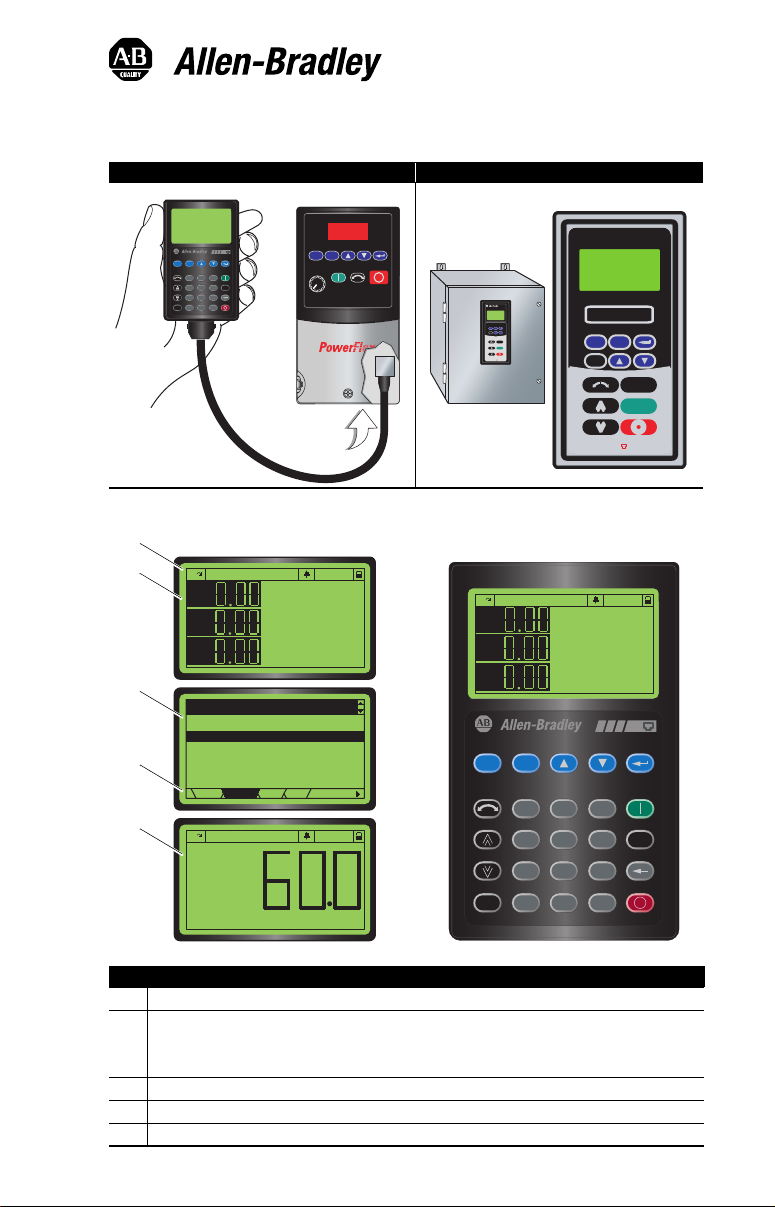
Human Interface Modules (HIM)
22-HIM-A3 — IP20 (NEMA Type 1) 22-HIM-C2S — IP66 (NEMA Type 4X/12)
DSI
Remove
Lang
View
Esc
Sel
7 8 9
Jog
4 5 6
1 2 3
.
Alt
0 +/-
Param #
Display Descriptions
➊
➋
F Stopped Auto
Hz
A
V
➌
➍
➎
Parameters
Groups
Linear List
Changed Params
DIAG DSEL MEM
PARAM
F At Reference Auto
Output Freq
SelEsc
E
V
REMO
P
DIS
Esc
Sel
G
LAN
ALT
Jog
|
DSI
F Stopped Auto
DISP
LANG
Esc
Sel
ALT
Jog
|
DSI
Hz
A
V
DSI
View Lang
Esc
Sel
SEL
7 8 9
4 5 6
1 2 3
.
Hz
Alt
0 +/-
Remove
Jog
Param #
Display
Status Line: Direction | Operating Status | Drive Status | Auto/Manual Mode | Parameters Locked/Unlocked
➊
Process Display screen:
➋
• Output Frequency
• User Display Line 1 (HIM Parameter 04)
• User Display Line 2 (HIM Parameter 05)
Programming screen
➌
Menu Navigation Tabs
➍
Large Format User Display screen:
➎
Page 2
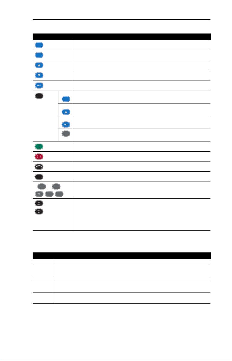
Key Descriptions
Keys Description
Esc
Sel
Alt
plus…
Jog
0
9
...
.
Exit a menu, cancel a change to a parameter value, or acknowledge a fault/alarm.
Select a digit, select a bit, or select a menu tab.
Scroll through options, increase a value, or toggle a bit.
Scroll through options, decrease a value, or toggle a bit.
Enter a menu, enter edit mode in a parameter screen, or save a change to a parameter
value.
View
Toggle between the Process Display and Large Format Display.
Sel
Select an available language for text displayed on HIM screens.
Lang
Allow the HIM to be disconnected without causing a fault condition.
Remove
Enable direct parameter number entry.
+/-
Param #
Start the drive.
Stop the drive or clear a fault.
Change direction.
Jog the drive.
Type parameter numbers and values.
+/-
Increase or decrease the speed Reference to the drive after these keys are enabled by
setting drive parameter P038 - [Speed Reference] as follows:
• When the HIM is the DSI Master, set parameter P038 to “5” (Comm Port).
• When the HIM is the DSI Slave, set parameter P038 to “1” (Internal Freq).
To view the HIM’s active device type status (Master or Slave), see HIM Parameter 10 [M/S Status].
Menu Navigation Tabs
Tabs Description
DIAG The Diagnostics tab is used to display faults, the device (drive or peripheral) status, and device version.
PARAM The Parameters tab is used to edit parameters. Parameters can be displayed in groups, in a linear list,
DSEL The Device Select tab is used to select the device (drive or peripheral) that the HIM is to access.
MEM The Memory Storage tab is used for HIM CopyCat (uploading/downloading configurations to the HIM
HIM The HIM Setup tab is used to access HIM parameters, view the HIM version, and to edit the Reference
or only those changed from their defaults.
EEPROM).
text when a user-defined Reference is used.
Page 3

Parameter List
Parameter
No. Name and Description Details
01 [Startup Display]
Selects the display screen shown when the HIM is powered up.
02 [Startup Param]
Selects a desired drive parameter to be displayed if Parameter 01 -
[Startup Display] is set to “3” (Startup Param).
03 Reserved
04 [User Disp Line 1]
Selects a desired drive parameter to be displayed on User Display
Line 1 of the Process Display screen.
For example, setting to “3” selects PowerFlex 4-Class drive
Parameter 3 - [Output Current] to be displayed.
05 [User Disp Line 2]
Selects a desired drive parameter to be displayed on User Display
Line 2 of the Process Display screen.
For example, setting to “5” selects PowerFlex 4-Class drive
Parameter 5 - [DC Bus Voltage] to be displayed.
06 [Large Disp Param]
Selects a desired drive parameter to be displayed on the Large
Format User Display screen.
For example, setting to “1” selects PowerFlex 4-Class drive
Parameter 1 - [Output Freq] to be displayed. Setting to “0” enables
the Scaled Reference to be displayed.
07 [LCD Contrast]
Sets the HIM LCD contrast level.
08 [Reset HIM]
1 (Reset): Resets the HIM.
2 (Set Defaults): Resets HIM parameters to factory settings.
This parameter returns to a value of “0” (Ready) after the reset
function is complete.
09 [Device Type]
Selects the HIM device type. When set to “0” (Auto), the HIM is
automatically configured as either a DSI Master or Slave depending
on the presence of other peripheral devices.
10 [M/S Status]
Displays the HIM active device type.
11 [HIM Ref Preset]
0 (Zero Start): HIM Reference is always “0.0” at power on.
1 (Host Output): HIM will assume the Host’s output feedback
2 (Last HIM Ref): HIM will store the HIM Reference in EEPROM each
(bumpless transfer) and preset its Reference when
the Reference is configured to be received on the
RS-485 port. This can be verified by viewing
Diagnostics/Device Status/Remote Freq Ref = 1.
time it is changed. HIM Reference is restored at
power on.
Default: 0 = Main Menu
Values 0 = Main Menu
Type: Read/Write
Default: 1
Minimum: 1
Maximum: 65535
Type: Read/Write
Default: 3
Minimum: 1
Maximum: 65535
Type: Read/Write
Default: 5
Minimum: 1
Maximum: 65535
Type: Read/Write
Default: 1
Minimum: 0
Maximum: 65535
Type: Read/Write
Default: 50%
Minimum: 0%
Maximum: 100%
Type: Read/Write
Default: 0 = Ready
Values 0 = Ready
Type: Read/Write
Default: 0 = Auto
Values 0 = Auto
Type: Read/Write
Default: N/A
Values 1 = Slave
Type: Read Only
Default: 0 = Zero Start
Values 0 = Zero Start
Type: Read/Write
1 = Process Disp
2 = Large Disp
3 = Startup Param
1 = Reset
2 = Set Defaults
1 = Slave
2 = Master
2 = Master
1 = Host Output
2 = Last HIM Ref
Page 4

Parameter
No. Name and Description Details
12 [Ref Scaling]
Enables or disables scaling the Reference to a user-defined value.
When Parameter 12 - [Ref Scaling] is set to “1” (Enabled), use HIM
Parameters 13…22 to scale the Reference.
13 [Ref Max Value]
Sets the user-defined value to be displayed when the drive is running
at 60 Hz.
14 [Ref Dec Position]
Sets the number of digits to be displayed to the right of the decimal
point for the Reference.
15
[Ref Units Char 1]
16
[Ref Units Char 2]
17
[Ref Units Char 3]
18
[Ref Units Char 4]
19
[Ref Units Char 5]
20
[Ref Units Char 6]
21
[Ref Units Char 7]
22
[Ref Units Char 8]
Selects up to 8 characters (from the ISO 8859-1 character set) to use
for the Reference units on the Process Display.
Parameters 15…22 can also be configured using the “Edit Ref Text”
selection in the HIM Setup tab.
23 [Fault Dspy Type]
Selects the type of display flash to be shown when a drive or
peripheral fault is detected.
24 [Alarm Dspy Type]
Selects the type of display flash to be shown when a drive alarm is
detected.
Default: 0 = Disabled
Values: 0 = Disabled
Type: Read/Write
Default: 600
Minimum: 100
Maximum: 65535
Type: Read/Write
Default: 1
Minimum: 0
Maximum: 3
Type: Read/Write
Default: 72 (“H”)
Default: 122 (“z”)
Default: 32 (blank - no character)
Default: 32 (blank - no character)
Default: 32 (blank - no character)
Default: 32 (blank - no character)
Default: 32 (blank - no character)
Default: 32 (blank - no character)
Minimum: 32
Maximum: 255
Type: Read/Write
Default: 0 = Flash Bklite
Values: 0 = Flash Bklite
Type: Read/Write
Default: 1 = Flash None
Values: 0 = Flash Bklite
Type: Read/Write
1 = Enabled
1 = Flash None
1 = Flash None
NOTE: New settings to HIM parameters are implemented immediately.
Resetting the HIM is not required for new values to take effect.
U.S. Allen-Bradley Drives Technical Support
Tel: (1) 262.512.8176, Fax: (1) 262.512.2222, Email: support@drives.ra.rockwell.com, Online: www.ab.com/support/abdrives
www.rockwellautomation.com
Power, Control and Information Solutions Headquarters
Americas: Rockwell Automation, 1201 South Second Street, Milwaukee, WI 53204-2496 USA, Tel: (1) 414.382.2000, Fax: (1) 414.382.4444
Europe/Middle East/Africa: Rockwell Automation, Vorstlaan/Boulevard du Souverain 36, 1170 Brussels, Belgium, Tel: (32) 2 663 0600, Fax: (32) 2 663 0640
Asia Pacific: Rockwell Automation, Level 14, Core F, Cyberport 3, 100 Cyberport Road, Hong Kong, Tel: (852) 2887 4788, Fax: (852) 2508 1846
Publication 22HIM-QR001F – September 2009
Supersedes 22HIM-QR001E-EN-P – April 2005 Copyright © 2009 Rockwell Automation, Inc. All rights reserved. Printed in USA.
 Loading...