

Page 1

ControlNet
Adapter
22-COMM-C
FRN 1.xxx
User Manual
Page 2
Important User Information
Solid state equipment has operational characteristics differing from those of
electromechanical equipment. Safety Guidelines for the Application, Installation and
Maintenance of Solid State Controls (Publication SGI-1.1 available from your local
Rockwell Automation sales office or online at http://www.rockwellautomation.com/
literature) describes some important differences between solid state equipment and
hard-wired electromechanical devices. Because of this difference, and also because
of the wide variety of uses for solid state equipment, all persons responsible for
applying this equipment must satisfy themselves that each intended application of
this equipment is acceptable.
In no event will Rockwell Automation, Inc. be responsible or liable for indirect or
consequential damages resulting from the use or application of this equipment.
The examples and diagrams in this manual are included solely for illustrative
purposes. Because of the many variables and requirements associated with any
particular installation, Rockwell Automation, Inc. cannot assume responsibility or
liability for actual use based on the examples and diagrams.
No patent liability is assumed by Rockwell Automation, Inc. with respect to use of
information, circuits, equipment, or software described in this manual.
Reproduction of the contents of this manual, in whole or in part, without written
permission of Rockwell Automation, Inc. is prohibited.
Throughout this manual, when necessary we use notes to make you aware of safety
considerations.
WARNING: Identifies information about practices or circumstances
that can cause an explosion in a hazardous environment, which may
lead to personal injury or death, property damage, or economic loss.
Important: Identifies information that is critical for successful application and
understanding of the product.
ATTENTION: Identifies information about practices or circumstances
that can lead to personal injury or death, property damage, or economic
loss. Attentions help you:
• identify a hazard
• avoid the hazard
• recognize the consequences
Shock Hazard labels may be located on or inside the equipment (e.g.,
drive or motor) to alert people that dangerous voltage may be present.
Burn Hazard labels may be located on or inside the equipment (e.g.,
drive or motor) to alert people that surfaces may be at dangerous
temperatures.
Allen-Bradley, PowerFlex, ControlLogix, PLC-5, DriveExplorer, DriveExecutive, DriveTools SP, and ControlFLASH are
either registered trademarks or trademarks of Rockwell Automation, Inc.
RSLogix, RSLinx, and RSNetWorx are trademarks of Rockwell Software.
ControlNet is a trademark of ControlNet International.
Windows and Microsoft are registered trademarks of Microsoft Corporation.
Page 3

Summary of Changes
The information below summarizes the changes made to this manual
since its last release (May 2005):
Description of New or Updated Information Page(s)
In the Chapter 4 introduction, added an Important paragraph about I/O
connections.
In the “About Explicit Messaging” section, added an Important paragraph
about “unconnected” and “connected” messages.
In the “Configuring the RS-485 Network” section, corrected the Important
paragraph text. The daisy-chained drive(s) parameter A106 - [Comm Loss
Time] is not used in Multi-Drive mode.
In the “ControlLogix Explicit Messaging” section, corrected these drive
parameter subheading names:
• Parameter D003 from [Current Output] to [Output Current]
• Parameter P039 from [Current Output] to [Accel Time 1]
In the “Environmental” specifications section, corrected the maximum
Farenheit Operating Temperature value from 149°F to 122°F.
4-1
6-1
7-7
7-22
A-2
Page 4

soc-ii Summary of Changes
Page 5

Preface About This Manual
Related Documentation . . . . . . . . . . . . . . . . . . . . . . . . . . . . . P-1
Conventions Used in this Manual . . . . . . . . . . . . . . . . . . . . . P-2
Rockwell Automation Support. . . . . . . . . . . . . . . . . . . . . . . . P-3
Chapter 1 Getting Started
Components . . . . . . . . . . . . . . . . . . . . . . . . . . . . . . . . . . . . . . 1-1
Features . . . . . . . . . . . . . . . . . . . . . . . . . . . . . . . . . . . . . . . . . 1-2
Compatible Products . . . . . . . . . . . . . . . . . . . . . . . . . . . . . . . 1-3
Required Equipment . . . . . . . . . . . . . . . . . . . . . . . . . . . . . . . 1-3
Safety Precautions . . . . . . . . . . . . . . . . . . . . . . . . . . . . . . . . . 1-4
Quick Start . . . . . . . . . . . . . . . . . . . . . . . . . . . . . . . . . . . . . . 1-5
Modes of Operation . . . . . . . . . . . . . . . . . . . . . . . . . . . . . . . . 1-6
Chapter 2 Installing the Adapter
Preparing for an Installation. . . . . . . . . . . . . . . . . . . . . . . . . . 2-1
Setting Operating Mode and Node Address Switches . . . . . . 2-1
Connecting the Adapter to the Network . . . . . . . . . . . . . . . . 2-3
Connecting the Adapter to the Drive . . . . . . . . . . . . . . . . . . . 2-4
Applying Power . . . . . . . . . . . . . . . . . . . . . . . . . . . . . . . . . . . 2-7
Chapter 3 Configuring the Adapter
Configuration Tools . . . . . . . . . . . . . . . . . . . . . . . . . . . . . . . . 3-1
Using the PowerFlex 4-Class HIM . . . . . . . . . . . . . . . . . . . . 3-2
Setting the Node Address. . . . . . . . . . . . . . . . . . . . . . . . . . . . 3-3
Setting the I/O Configuration. . . . . . . . . . . . . . . . . . . . . . . . . 3-3
Setting a Fault Action . . . . . . . . . . . . . . . . . . . . . . . . . . . . . . 3-4
Resetting the Adapter . . . . . . . . . . . . . . . . . . . . . . . . . . . . . . 3-6
Viewing the Adapter Configuration . . . . . . . . . . . . . . . . . . . . 3-7
Table of Contents
Chapter 4 Configuring the I/O
Chapter 5 Using the I/O
ControlLogix Example . . . . . . . . . . . . . . . . . . . . . . . . . . . . . 4-1
PLC-5 Example . . . . . . . . . . . . . . . . . . . . . . . . . . . . . . . . . . 4-12
About I/O Messaging . . . . . . . . . . . . . . . . . . . . . . . . . . . . . . . 5-1
Understanding the I/O Image . . . . . . . . . . . . . . . . . . . . . . . . . 5-2
Using Logic Command/Status . . . . . . . . . . . . . . . . . . . . . . . . 5-3
Using Reference/Feedback . . . . . . . . . . . . . . . . . . . . . . . . . . 5-3
Example Ladder Logic Program Information . . . . . . . . . . . . 5-4
ControlLogix Example . . . . . . . . . . . . . . . . . . . . . . . . . . . . . 5-5
PLC-5 Example . . . . . . . . . . . . . . . . . . . . . . . . . . . . . . . . . . . 5-8
Page 6

ii Table of Contents
Chapter 6 Using Explicit Messaging
About Explicit Messaging . . . . . . . . . . . . . . . . . . . . . . . . . . . 6-1
Performing Explicit Messages . . . . . . . . . . . . . . . . . . . . . . . 6-2
ControlLogix Example . . . . . . . . . . . . . . . . . . . . . . . . . . . . . 6-3
PLC-5 Example . . . . . . . . . . . . . . . . . . . . . . . . . . . . . . . . . . . 6-6
Chapter 7 Using Multi-Drive Mode
Single Mode vs. Multi-Drive Mode . . . . . . . . . . . . . . . . . . . . 7-1
System Wiring . . . . . . . . . . . . . . . . . . . . . . . . . . . . . . . . . . . . 7-4
Understanding the I/O Image . . . . . . . . . . . . . . . . . . . . . . . . . 7-5
Configuring the RS-485 Network . . . . . . . . . . . . . . . . . . . . . 7-7
Example Configuration Settings . . . . . . . . . . . . . . . . . . . . . . 7-8
ControlLogix I/O Example . . . . . . . . . . . . . . . . . . . . . . . . . . 7-9
ControlLogix Explicit Messaging . . . . . . . . . . . . . . . . . . . . 7-22
PLC-5 I/O Example . . . . . . . . . . . . . . . . . . . . . . . . . . . . . . 7-24
Additional Information . . . . . . . . . . . . . . . . . . . . . . . . . . . . 7-36
Chapter 8 Troubleshooting
Locating the Status Indicators . . . . . . . . . . . . . . . . . . . . . . . . 8-1
PORT Status Indicator . . . . . . . . . . . . . . . . . . . . . . . . . . . . . . 8-2
MOD Status Indicator . . . . . . . . . . . . . . . . . . . . . . . . . . . . . . 8-3
Net A and B Status Indicators Together. . . . . . . . . . . . . . . . . 8-4
Net A or B Status Indicators Independently . . . . . . . . . . . . . 8-4
Adapter Diagnostic Items in Single Mode . . . . . . . . . . . . . . 8-5
Adapter Diagnostic Items in Multi-Drive Mode . . . . . . . . . . 8-6
Viewing and Clearing Events. . . . . . . . . . . . . . . . . . . . . . . . . 8-7
Appendix A Specifications
Communications . . . . . . . . . . . . . . . . . . . . . . . . . . . . . . . . . A-1
Electrical . . . . . . . . . . . . . . . . . . . . . . . . . . . . . . . . . . . . . . . A-1
Mechanical . . . . . . . . . . . . . . . . . . . . . . . . . . . . . . . . . . . . . . A-1
Environmental . . . . . . . . . . . . . . . . . . . . . . . . . . . . . . . . . . . A-2
Regulatory Compliance . . . . . . . . . . . . . . . . . . . . . . . . . . . . A-2
Appendix B Adapter Parameters
About Parameter Numbers. . . . . . . . . . . . . . . . . . . . . . . . . . . B-1
Parameter List . . . . . . . . . . . . . . . . . . . . . . . . . . . . . . . . . . . . B-1
Page 7

Appendix C ControlNet Objects
Identity Object . . . . . . . . . . . . . . . . . . . . . . . . . . . . . . . . . . . . C-2
Assembly Object . . . . . . . . . . . . . . . . . . . . . . . . . . . . . . . . . . C-4
Register Object. . . . . . . . . . . . . . . . . . . . . . . . . . . . . . . . . . . . C-6
Parameter Object . . . . . . . . . . . . . . . . . . . . . . . . . . . . . . . . . . C-9
Parameter Group Object (Single Mode only) . . . . . . . . . . . C-12
PCCC Object . . . . . . . . . . . . . . . . . . . . . . . . . . . . . . . . . . . . C-14
DSI Device Object . . . . . . . . . . . . . . . . . . . . . . . . . . . . . . . C-20
DSI Parameter Object . . . . . . . . . . . . . . . . . . . . . . . . . . . . . C-23
DSI Fault Object . . . . . . . . . . . . . . . . . . . . . . . . . . . . . . . . . C-27
DSI Diagnostic Object . . . . . . . . . . . . . . . . . . . . . . . . . . . . . C-29
Appendix D Logic Command/Status Words
PowerFlex 4/40/400 Drives . . . . . . . . . . . . . . . . . . . . . . . . . D-1
Glossary
Index
Table of Contents iii
Page 8

iv Table of Contents
Page 9

Preface
About This Manual
Topic Page
Related Documentation
Conventions Used in this Manual P-2
Rockwell Automation Support P-3
Related Documentation
For: Refer to: Publication
DriveExplorer™ http://www.ab.com/drives/driveexplorer, and
DriveTools™ SP (includes
DriveExecutive™)
HIM HIM Quick Reference 22HIM-QR001…
Powe rFlex
Powe rFlex
Powe rFlex
RSLinx™
or RSLinx Lite
RSLogix™ 5
RSLogix™ 5000
RSNetWorx™ for
ControlNet™
ControlLogix
1756-CNB/R
®
4 Drive PowerFlex 4 User Manual
®
40 Drive PowerFlex 40 User Manual
®
400 Drive PowerFlex 400 User Manual 22C-UM001…
®
and
DriveExplorer online Help (installed with the software)
http://www.ab.com/drives/drivetools, and
DriveTools SP online Help (installed with the software)
PowerFlex 4 Quick Start
PowerFlex 40 Quick Start
Getting Results with RSLinx Guide,
and online help (installed with the software)
RSLogix 5 Getting Results Guide*
RSLogix 5000 Getting Results Guide*
* And online help (installed with the software)
RSNetWorx for ControlNet Getting Results Guide,
and online help (installed with the software)
ControlLogix ControlNet Interface Module User Manual 1756-6.5.3
P-1
—
—
22A-UM001…
22A-QS001…
22B-UM001…
22B-QS001…
LINX-GR001…
LG5-GR001…
9399-RLD300GR
CNET-GR001…
Documentation can be obtained online at
http://www.rockwellautomation.com/literature
.
Page 10

P-2 About This Manual
Conventions Used in this Manual
The following conventions are used throughout this manual:
• Parameter names are shown in the format Parameter xx - [*]. The xx
represents the parameter number, and the * represents the parameter
name — for example, Parameter 01 - [Mode].
• Menu commands are shown in bold type face and follow the format
Menu > Command. For example, if you read “Select File > Open,”
you should click the File menu and then click the Open command.
• The firmware release is displayed as FRN X.xxx. The “FRN”
signifies Firmware Release Number. The “X” is the major release
number. The “xxx” is the minor update number.
• RSNetWorx for ControlNet (version 5.11), RSLinx (version 2.43),
RSLogix 5000 (version 13.03) and RSLogix 5 (version 6.30) were
used for the screen shots in this manual. Different versions of the
software may differ in appearance and procedures.
• This manual provides information about the 22-COMM-C ControlNet
adapter and using it with PowerFlex 4-Class drives. The adapter can
be used with other products that support a DSI adapter, such as the
DSI External Comms Kit (22-XCOMM-DC-BASE). Refer to the
documentation for your product for specific information about how it
works with the adapter.
Page 11

About This Manual P-3
Rockwell Automation Support
Rockwell Automation, Inc. offers support services worldwide, with over
75 sales/support offices, over 500 authorized distributors, and over 250
authorized systems integrators located through the United States alone.
In addition, Rockwell Automation, Inc. representatives are in every
major country in the world.
Local Product Support
Contact your local Rockwell Automation, Inc. representative for:
• Sales and order support
• Product technical training
• Warranty support
• Support service agreements
Technical Product Assistance
If you need to contact Rockwell Automation, Inc. for technical
assistance, please review the information in Chapter 8
first. If you still have problems, then call your local Rockwell
Automation, Inc. representative.
, Troubleshooting
U.S. Allen-Bradley Drives Technical Support:
E-mail: support@drives.ra.rockwell.com
Tel: (1) 262.512.8176
Fax (1) 262.512.2222
Online: www.ab.com/support/abdrives
UK Customer Support Center:
E-mail: esupport2@ra.rockwell.com
Tel: +44 (0) 870 2411802
Fax: +44 (0) 1908 838804
Germany Customer Service Center:
E-mail: ragermany-csc@ra.rockwell.com
Tel: +49 (0) 2104 960-630
Fax: +49 (0) 2104 960-501
Page 12

P-4 About This Manual
Notes:
Page 13
Chapter 1
Getting Started
The 22-COMM-C ControlNet adapter is a communication option
intended for installation into a PowerFlex 40 or PowerFlex 400 drive. It
can also be used with other Allen-Bradley products that support a DSI
communication adapter, such as the DSI External Comms Kit
(22-XCOMM-DC-BASE). The External Comms Kit enables PowerFlex
4 drives (which cannot support an internally-mounted adapter) to
connect to a ControlNet network.
Topic Page Topic Page
Components
Features 1-2 Quick Start 1-5
Compatible Products 1-3 Modes of Operation 1-6
Required Equipment 1-3
1-1 Safety Precautions 1-4
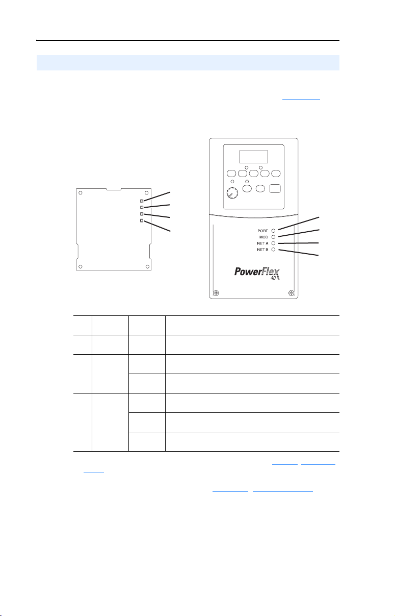
Components
Figure 1.1 Components of the Adapter
➊
➋
LEDs are located
on bottom side of
adapter board
➏
➌➍
Item Component Description
Status Indicators Four LEDs that indicate the status of the ControlNet connection,
➊
DSI Connector A 20-pin, single-row shrouded male header. An Internal Interface
➋
Channel A Coax Receptacle Channel A BNC connection for the ControlNet cable.
➌
Channel B Coax Receptacle Channel B BNC connection for the ControlNet cable.
➍
1x/5x Operating Mode
➎
Jumper (J7)
ControlNet Node Address
➏
Switches
DSI, and the adapter. Refer to Chapter 8, Troubleshooting.
cable is connected to this connector and a connector on the drive.
Selects Single (1x) or Multi-Drive (5x) mode of operation. Refer to
Setting Operating Mode and Node Address Switches
Sets a unique node address for the adapter. Refer to Setting
Operating Mode and Node Address Switches on page 2-1.
➎
on page 2-1.
Page 14

1-2 Getting Started
Features
The ControlNet adapter features the following:
• The adapter is normally installed in a PowerFlex 40 or PowerFlex 400
drive. It can also be used in a DSI External Comms Kit
(22-XCOMM-DC-BASE).
• A jumper lets you select between Single or Multi-Drive mode of
operation. In Single mode (default), the adapter represents a single
drive on one node. In Multi-Drive mode, the adapter represents up to
5 drives on one node.
• A number of configuration tools can be used to configure the adapter
and connected drive. The tools include an external PowerFlex 4-Class
HIM (22-HIM-*) or drive-configuration software such as
DriveExplorer (version 3.01 or higher) or DriveExecutive (version
3.01 or higher).
• Status indicators report the status of drive communications, the
adapter, and network.
• Supports I/O, including Logic Command/Reference, for all drives
connected in Single or Multi-Drive mode.
• The following table shows the various controllers that can be used
with the 22-COMM-C adapter and whether they support explicit
messaging (parameter read/write, etc.) on a ControlNet network:
Supports Explicit Messaging
Controller Used With 22-COMM-C
ControlLogix 1756-L55/L61/L62/L63 ✔✔
FlexLogix 1794-L33/L34 ✔✔
CompactLogix 1769-L20/L30/L35E ✔✔
MicroLogix1000 1761-L10/L16/L20/L32 ✔✔
MicroLogix1200 1762-L24/L40 ✔✔
MicroLogix1500 1764-LSP/LRP ✔✔
PLC-5 1785-L20C/L40C/L46C/L80C ✔
SoftLogix 1789-L10/L30/L60 ✔✔
(1)
Due to controller limitations, explicit messaging can only be performed on drive
parameters up to Parameter 256.
• User-defined fault actions determine how the adapter and drive (or
DSI External Comms Kit) respond to communication disruptions on
the network and controllers in program mode.
Single Mode Multi-Drive
Yes N o Yes No
(1)
✔
Page 15

Getting Started 1-3
Compatible Products
The adapter is compatible with Allen-Bradley PowerFlex 4-Class
(Component-Class) drives and other products that support an internal
DSI adapter. At the time of publication, compatible products include:
• PowerFlex 4 drives with DSI External Comms Kit
• PowerFlex 40 drives
• PowerFlex 400 drives
Required Equipment
Equipment Shipped with the Adapter
When you unpack the adapter, verify that the package includes:
❑ One ControlNet adapter
❑ One 15.24 cm (6 in.) Internal Interface Cable
❑ This manual
User-Supplied Equipment
To install and configure the adapter, you must supply:
❑ A small flathead screwdriver
❑ Appropriate ControlNet cables (refer to the ControlNet Fiber Media
Planning and Installation Guide, Publication CNET-IN001…, for
details.)
❑ A configuration tool, such as:
– PowerFlex 4-Class HIM (22-HIM-*)
– DriveExplorer (version 3.01 or higher)
– DriveExecutive stand-alone software (version 3.01 or higher) or
bundled with the DriveTools SP suite (version 1.01 or higher)
– RSNetWorx for ControlNet
❑ Controller configuration software (Example: RSLogix 5000)
❑ A PC connection to the ControlNet network
Page 16
1-4 Getting Started
Safety Precautions
Please read the following safety precautions carefully.
ATTENTION: Risk of injury or death exists. The PowerFlex drive
may contain high voltages that can cause injury or death. Remove
!
power from the PowerFlex drive, and then verify power has been
discharged before installing or removing the adapter.
ATTENTION: Risk of injury or equipment damage exists. Only
personnel familiar with drive and power products and the associated
!
machinery should plan or implement the installation, start-up,
configuration, and subsequent maintenance of the product using the
adapter. Failure to comply may result in injury and/or equipment
damage.
ATTENTION: Risk of equipment damage exists. The adapter
contains ESD (Electrostatic Discharge) sensitive parts that can be
!
damaged if you do not follow ESD control procedures. Static control
precautions are required when handling the adapter. If you are
unfamiliar with static control procedures, refer to Guarding Against
Electrostatic Damage, Publication 8000-4.5.2.
ATTENTION: Risk of injury or equipment damage exists. If the
adapter is transmitting control I/O to the drive, the drive may fault when
!
you reset the adapter. Determine how your drive will respond before
resetting the adapter.
ATTENTION: Risk of injury or equipment damage exists. Parameters
08 - [Comm Flt Action] and 09 - [Idle Flt Action] let you determine the
!
action of the adapter and connected PowerFlex drive if communications
are disrupted. By default, these parameters fault the drive. You can set
these parameters so that the drive continues to run. Precautions should be
taken to ensure that the settings of these parameters do not create a risk
of injury or equipment damage. When commissioning the drive, verify
that your system responds correctly to various situations (for example, a
disconnected cable or a faulted controller).
ATTENTION: Risk of injury or equipment damage exists. When a
system is configured for the first time, there may be unintended or
!
incorrect machine motion. Disconnect the motor from the machine or
process during initial system testing.
ATTENTION: Risk of injury or equipment damage exists. The
examples in this publication are intended solely for purposes of
!
example. There are many variables and requirements with any
application. Rockwell Automation, Inc. does not assume responsibility
or liability (to include intellectual property liability) for actual use of
the examples shown in this publication.
Page 17
Getting Started 1-5
Quick Start
This section is provided to help experienced users quickly start using the
adapter. If you are unsure how to complete a step, refer to the referenced
chapter.
Step Refer to …
1 Review the safety precautions for the adapter. Throughout this
2 Verify that the PowerFlex drive is properly installed. Drive User Manual
3 Install the adapter.
Verify that the PowerFlex drive is not powered. Then,
connect the adapter to the network using a ControlNet cable
and to the drive using the Internal Interface cable. Use the
captive screw to secure and ground the adapter to the drive.
When installing the adapter in a DSI External Comms Kit,
refer to the 22-XCOMM-DC-BASE Installation Instructions
(Publication No. 22COMM-IN001…) supplied with the kit.
4 Apply power to the adapter.
The adapter receives power from the drive. Apply power to
the drive. The status indicators should be green. If they flash
red, there is a problem. Refer to Chapter 8
5 Configure the adapter for your application.
Set the following parameters for the adapter as required by
your application:
• I/O configuration
• Fault actions
6 Apply power to the ControlNet scanner and other
devices on the network.
Verify that the scanner and network are installed and
functioning in accordance with ControlNet standards, and
then apply power to them.
7 Configure the scanner or bridge to communicate with
the adapter.
Use a network tool such as RSNetWorx for ControlNet to
configure the scanner or bridge on the network.
8 Create a ladder logic program.
Use a programming tool such as RSLogix to create a ladder
logic program that enables you to:
• Control the adapter and connected drive using I/O.
• Monitor or configure the drive using Explicit Messages.
, Troubleshooting.
manual
,
Chapter 2
Installing the
Adapter
Chapter 2
,
Installing the
Adapter
,
Chapter 3
Configuring the
Adapter
—
Chapter 4
,
Configuring the I/O
,
Chapter 5
Using the I/O
Chapter 6,
Using Explicit
Messaging
Page 18
1-6 Getting Started
Modes of Operation
The adapter uses four status indicators to report its operating status. They
can be viewed on the adapter or through the drive cover (Figure 1.2).
Figure 1.2 Status Indicators (location on drive may vary)
Bottom side
of adapter board
➊
➋
➌
➍
➊
➋
➌
➍
Status
Item
Indicator
PORT Green Normal Operation. The adapter is properly connected and
➊
MOD Green Normal Operation. The adapter is operational and is
➋
NET A or
➌
NET B
➍
(1)
If all status indicators are off, the adapter is not receiving power. Refer to Chapter 2, Installing the
Adapter, for instructions on installing the adapter.
If any other conditions occur, refer to Chapter 8, Troubleshooting.
Normal
Status
Flashing
Green
Green Normal Operation. The adapter channel is properly
Flashing
Green
Off Normal Operation. The adapter channel is disabled or not
Description
(1)
is communicating with the drive.
transferring I/O data.
Normal Operation. The adapter is operational but is not
transferring I/O data.
connected and communicating on the network.
Normal Operation. The adapter channel has a temporary
error, or is in listen-only mode.
supported.
Page 19

Chapter 2
Installing the Adapter
Chapter 2 provides instructions for installing the adapter in a PowerFlex
40 or PowerFlex 400 drive. This adapter can also be installed in a DSI
External Comms Kit. In this case, refer to the 22-XCOMM-DC-BASE
Installation Instructions (Publication No. 22COMM-IN001…) supplied
with the kit.
Topic Page
Preparing for an Installation
Setting Operating Mode and Node Address Switches 2-1
Connecting the Adapter to the Network 2-3
Connecting the Adapter to the Drive 2-4
Applying Power 2-7
2-1
Preparing for an Installation
Before installing the adapter, verify that you have all required
equipment. Refer to Chapter 1
, Getting Started.
Setting Operating Mode and Node Address Switches
Before installing the adapter, you must set its Operating Mode Jumper
for Single or Multi-Drive operation, and its Node Address Switches to a
unique ControlNet node address.
Important: New settings are recognized only when power is applied to
the adapter, or the adapter is reset. If you change a setting,
cycle power or reset the adapter to invoke the change.
ATTENTION: Risk of equipment damage exists. The adapter
contains ESD (Electrostatic Discharge) sensitive parts that can be
!
damaged if you do not follow ESD control procedures. Static control
precautions are required when handling the adapter. If you are
unfamiliar with static control procedures, refer to Guarding Against
Electrostatic Damage, Publication 8000-4.5.2.
Page 20
2-2 Installing the Adapter
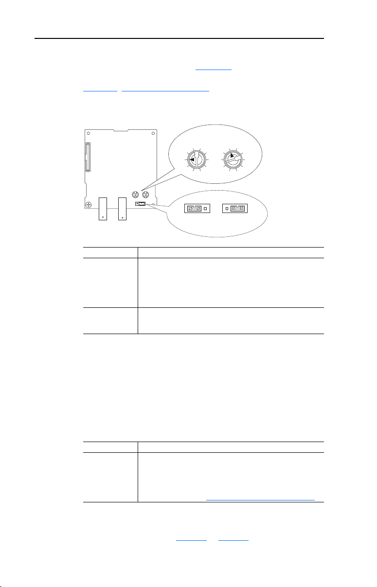
1. Set the adapter Operating Mode Jumper (J7) for Single (1x) or
Multi-Drive (5x) operation (see Figure 2.1
below). For complete details on Multi-Drive mode operation, see
Chapter 7, Using Multi-Drive Mode.
Figure 2.1 Setting Single/Multi-Drive Operation and Node Address Switches
and setting descriptions
4
5
6
Node Address
Switches
Operating
Mode Jumper
S2 S3
(Tens Digit) (Ones Digit)
2
3
2
1
4
0
6
9
7
8
J7
5x 1x
Mode
Jumper Setting Description
Right (1x)
position or jumper
missing
Left (5x) position Sets the adapter for Multi-Drive mode using up to 5 different
Sets the adapter for Single mode (default setting) using a single
drive connection.
Important: In this mode, connections to multiple drives must be
removed since all powered and connected hosts will respond to
any message sent by the adapter.
drives. DSI peripherals (22-HIM-*, 22-SCM-*, etc.) do not
operate with the adapter in this mode.
3
1
5
0
9
7
8
J7
Single ModeMulti-Drive
2. Set the adapter node address by rotating the Node Address Switches
to the desired value for each digit.
Important: Each node on the network must have a unique address.
The node address must be set before power is applied
because the adapter uses the node address it detects
when it first receives power. To change a node address,
you must set the new value. Then remove and reapply
power to the adapter, or reset the adapter.
Switch Settings Description
00-99 Node address used by the adapter if switches are enabled. The
default switch setting is 02.
Important: If the address switches are set to “00,” the adapter
will use the setting of Parameter 02 - [CN Addr Cfg] for the
node address. Refer to Setting the Node Address
on page 3-3.
The node address switch settings can be verified using a PowerFlex
4-Class HIM, DriveExplorer, or DriveExecutive to view Diagnostic
Item number 28 (listed on page 8-5
or page 8-6).
Page 21
Installing the Adapter 2-3
Connecting the Adapter to the Network
ATTENTION: Risk of injury or death exists. The PowerFlex drive
may contain high voltages that can cause injury or death. Remove
!
power from the PowerFlex drive, and then verify power has been
discharged before installing or removing an adapter.
1. Remove power from the drive.
2. Use static control precautions.
3. Remove the drive cover.
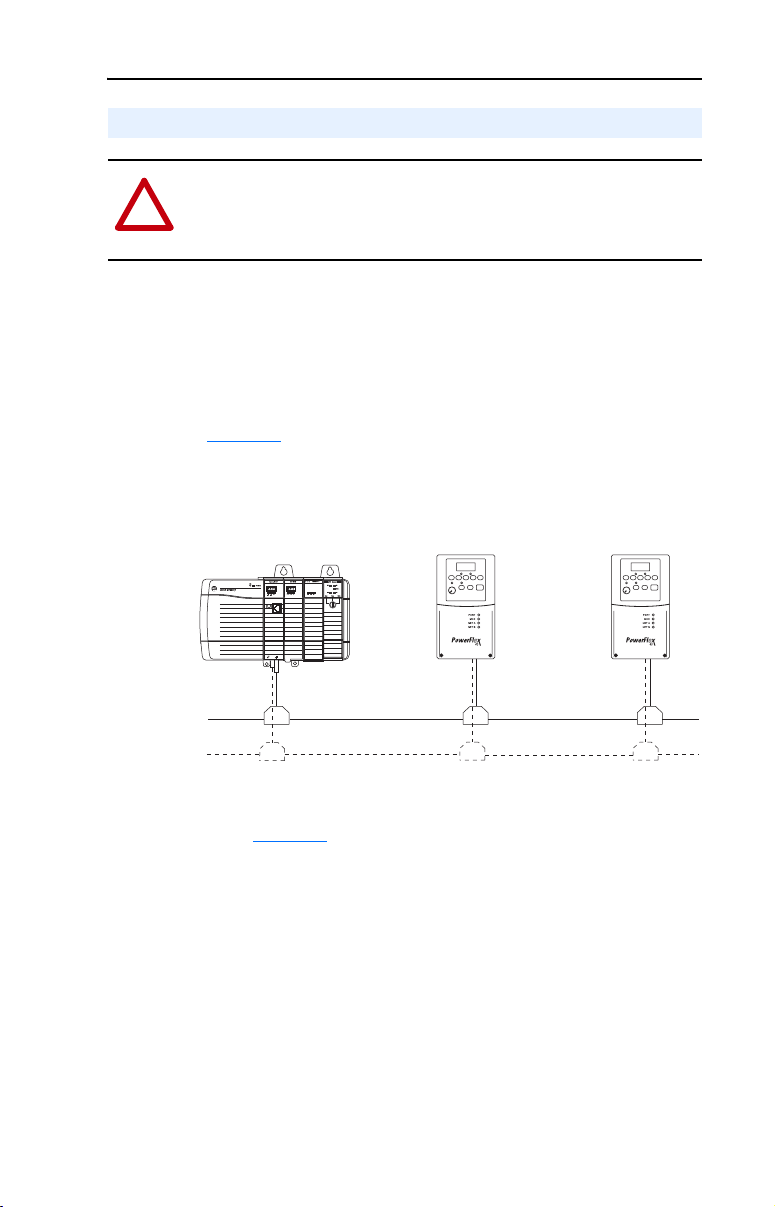
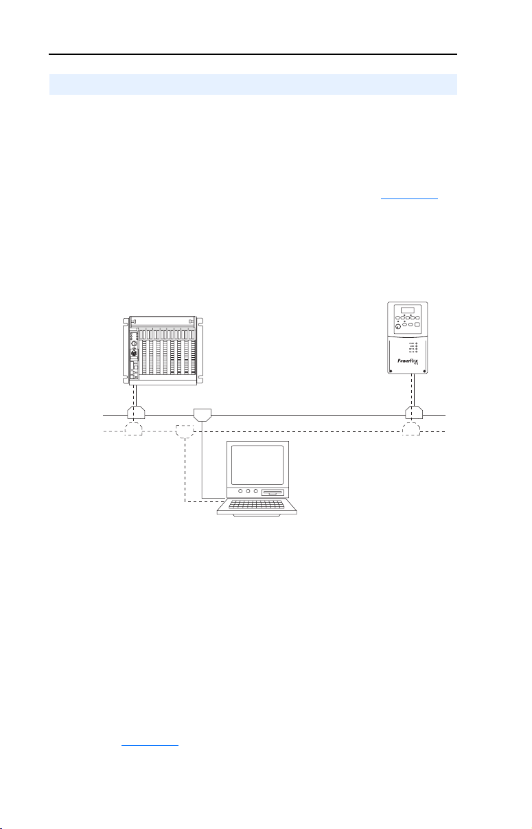
4. Connect a ControlNet cable to the ControlNet network. See
Figure 2.2
Figure 2.2 Connecting the ControlNet Cable to the Network
for an example of wiring to a ControlNet network.
ControlLogix Controller
with 1756-CNB/R
ControlNet Network
5. Route the ControlNet cable through the bottom of the PowerFlex
drive (Figure 2.3), and insert the cable plug into the adapter’s mating
receptacle.
PowerFlex 40 or PowerFlex 400 Drives
(each with a 22-COMM-C ControlNet Adapter)
(optional redundancy)
Page 22
2-4 Installing the Adapter
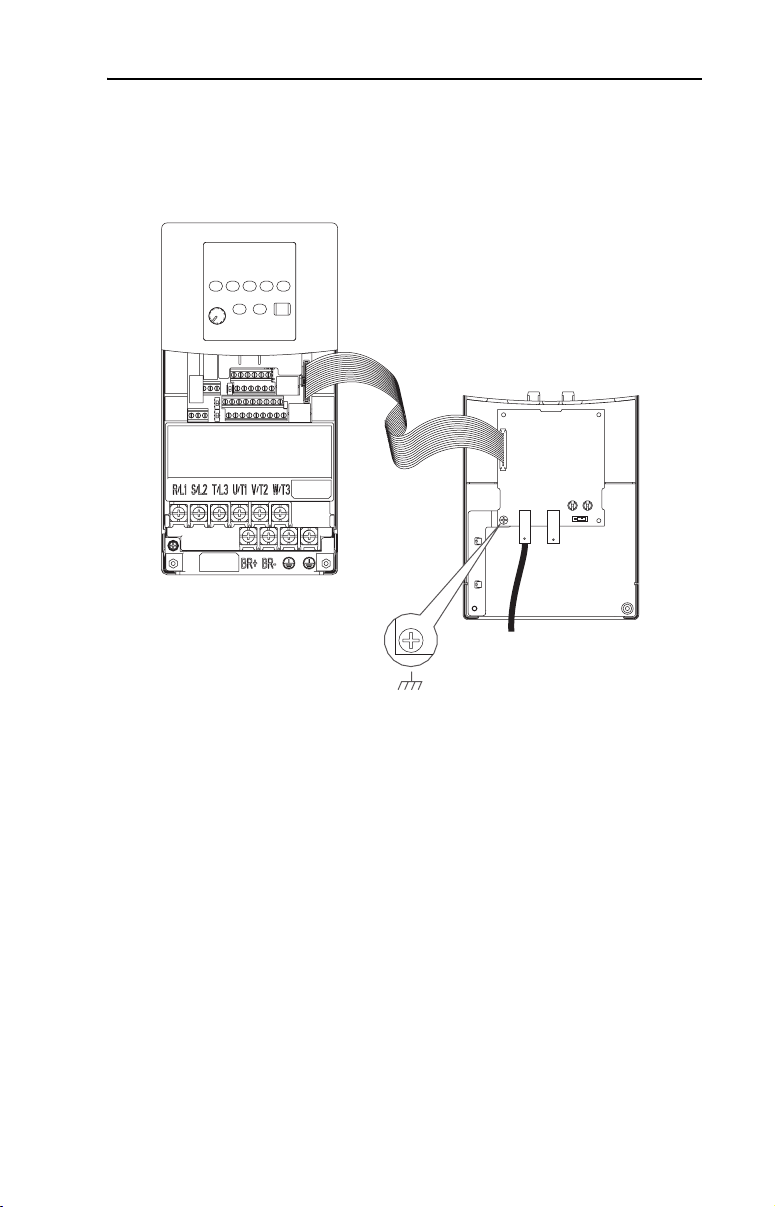
Connecting the Adapter to the Drive
PowerFlex 40 Frames B and C, and PowerFlex 400 Frame C
1. Remove power from the drive.
2. Use static control precautions.
3. Mount the adapter on the required special drive cover (ordered
separately — see Figure 2.4
• Frame C: Use the adapter screw to secure the adapter to the cover.
• Frame B: Disregard the screw and snap the adapter in place.
Important: For Frame C drives, tighten the adapter’s lower left
screw to ground the adapter (see Figure 2.4
B drives, install the special drive cover onto the drive
using both cover fasteners to ground the adapter.
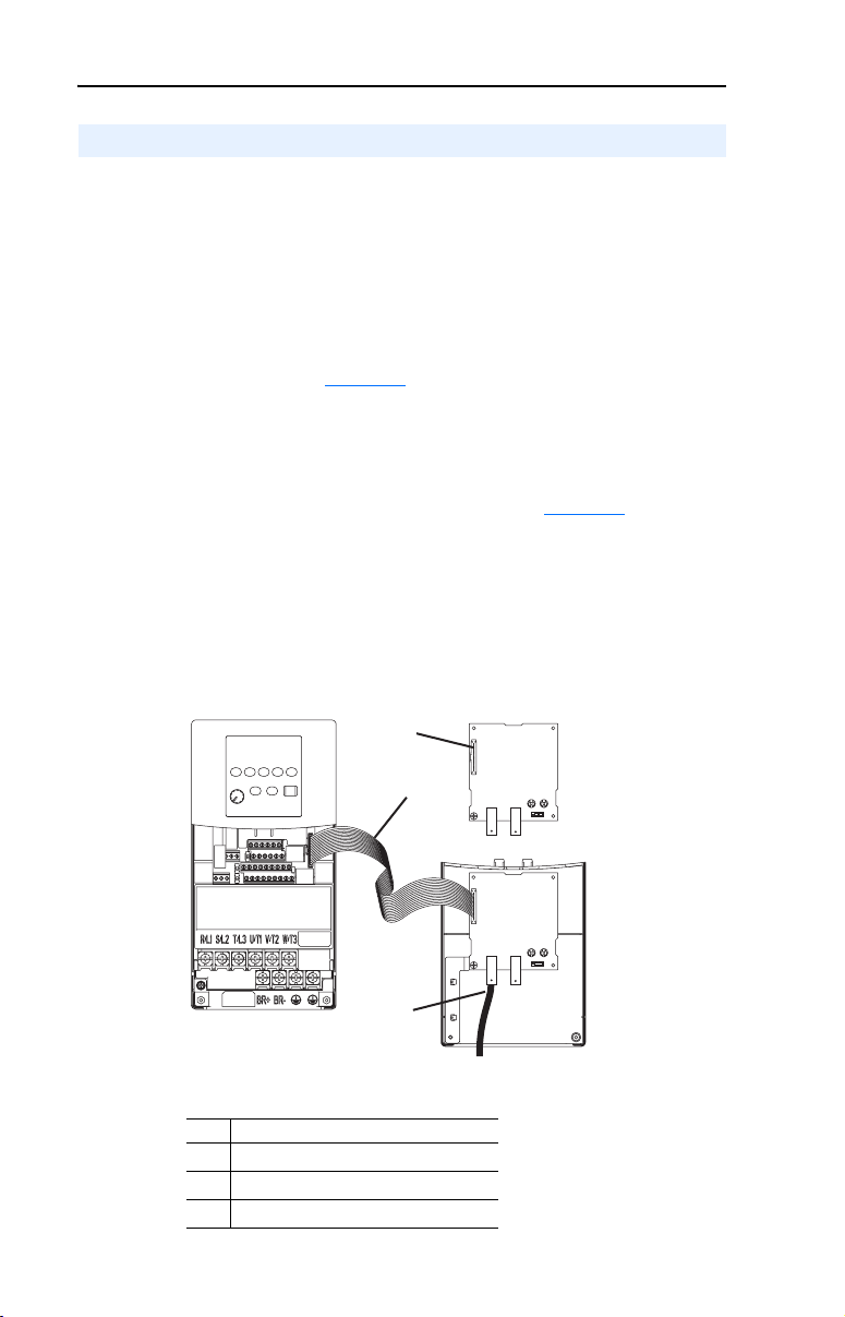
4. Connect the Internal Interface cable to the DSI port on the drive and
then to the mating DSI connector on the adapter.
Figure 2.3 Connecting DSI Ports with Internal Interface Cable
for part numbers).
). For Frame
PowerFlex 40 Drive
(Frame C shown
with cover removed)
Item Description
DSI connector
➊
15.24 cm (6 in.) Inter nal Interface cable
➋
ControlNet cable
➌
22-COMM-C Adapter
➊
➋
➌
Back of Required
Special Drive Cover
Page 23
Installing the Adapter 2-5
Figure 2.4 Mounting and Grounding the Adapter – PowerFlex 40 Frames B and C, and
PowerFlex 400 Frame C
Adapter Mounted on Back of
Required Special Drive Cover
(Frame C cover shown)
PowerFlex 40 Frame B -- Part Number 22B-CCB
PowerFlex 40 Frame C -- Part Number 22B-CCC
PowerFlex 400 Frame C -- Part Number 22C-CCC
PowerFlex 40 Drive
(Frame C shown
with cover removed)
Ground for Frame C Drives
For Frame B drives, the lower left
NOTE:
adapter screw does not ground the adapter.
To ground the adapter, install the special drive
cover onto the drive using both cover fasteners.
Page 24
2-6 Installing the Adapter
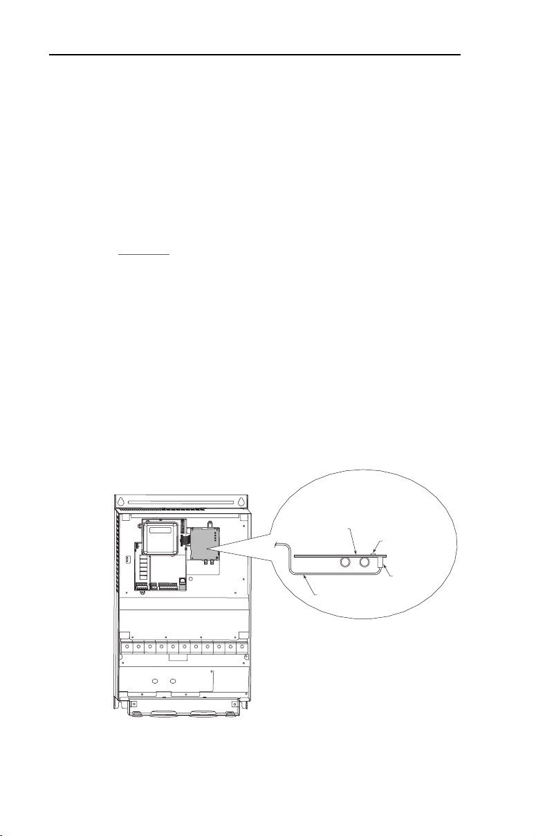
PowerFlex 400 Frames D, E, and F
1. Remove power from the drive.
2. Use static control precautions.
3. Remove the drive cover.
4. With the adapter board right side up, remove its mounting screw
from the lower left hole. Save the screw for mounting in Step 7.
5. Connect the Internal Interface cable to the DSI port on the drive (see
Figure 2.5
6. With the adapter board oriented bottom side up, route the Internal
Interface cable under the adapter, and then to the mating DSI
connector on the adapter.
7. Install the adapter, bottom side up, to the right side of the display
board by snapping it into place. Then insert the adapter mounting
screw into the lower left hole on the board.
Important: Tighten the mounting screw in the adapter’s lower left
).
hole to ground the adapter to the drive.
Figure 2.5 Mounting and Connecting the Adapter – PowerFlex 400 Frame D, E,
and F Drives
PowerFlex 400
(Frame D shown
with cover removed)
Adapter Installation
(Side View)
Bottom of
Adapter Board
Internal Interface
Ribbon Cable
LEDs
Connector
Page 25

Installing the Adapter 2-7
Applying Power
ATTENTION: Risk of equipment damage, injury, or death exists.
Unpredictable operation may occur if you fail to verify that parameter
!
settings and switch settings are compatible with your application.
Verify that settings are compatible with your application before
applying power to the drive.
1. Install the drive cover. The status indicators can be viewed on the
front of the drive after power has been applied.
2. Apply power to the PowerFlex drive. The adapter receives its power
from the connected drive. When you apply power to the adapter for
the first time, the status indicators should be green or off after an
initialization. If the status indicators are red, there is a problem.
Refer to Chapter 8
, Troubleshooting.
Page 26

2-8 Installing the Adapter
Notes:
Page 27
Chapter 3
Configuring the Adapter
Chapter 3 provides instructions and information for setting the
parameters in the adapter.
Topic Page
Configuration Tools
Using the PowerFlex 4-Class HIM 3-2
Setting the Node Address 3-3
Setting the I/O Configuration 3-3
Setting a Fault Action 3-4
Resetting the Adapter 3-6
Viewing the Adapter Configuration 3-7
For a list of parameters, refer to Appendix B, Adapter Parameters. For
definitions of terms in this chapter, refer to the Glossary
3-1
.
Configuration Tools
The adapter stores parameters and other information in its own
non-volatile memory. You must, therefore, access the adapter to view
and edit its parameters. The following tools can be used to access the
adapter parameters:
Tool Refer to…
PowerFlex 4-Class HIM
(22-HIM-*)
DriveExplorer Software
(version 3.01 or higher)
DriveExecutive Software
(version 3.01 or higher)
page 3-2
http://www.ab.com/drives/driveexplorer, and
DriveExplorer online help (installed with the software)
http://www.ab.com/drives/drivetools, and
DriveExecutive online help (installed with the software)
Page 28
3-2 Configuring the Adapter
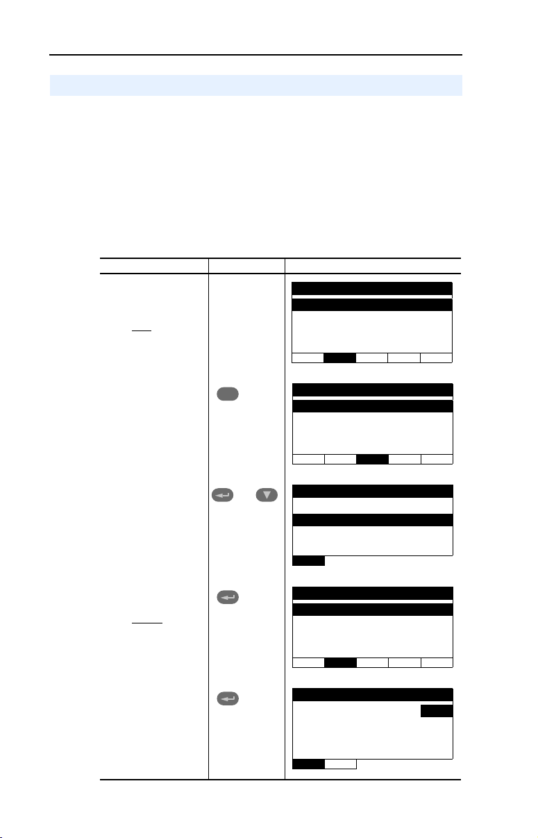
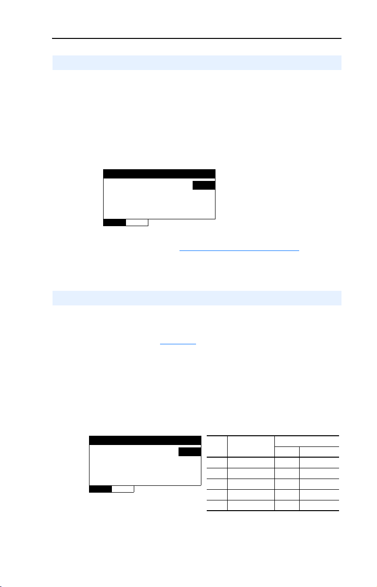
Using the PowerFlex 4-Class HIM
The PowerFlex 4-Class HIM (Human Interface Module) can be used to
access parameters in the adapter (see basic steps shown below). It is
recommended that you read through the steps for your HIM before
performing the sequence. For additional HIM information, refer to the
HIM Quick Reference card.
Note: The HIM will only work when the adapter is set to Single mode.
Using the HIM
Step Key(s) Example Screens
1. Power up the drive.
Then plug the HIM
into the drive. The
Parameters menu for
will be
the drive
displayed.
2. Press Sel key once to
display the Device
Select menu.
Sel
Parameters
Groups
Linear List
Changed Params
DIAG PA R A M DSEL MEM SEL !
Device Select
DSI Devices
3. Press Enter to display
the DSI Devices
menu. Press Down
Arrow to scroll to
22-COMM-C.
4. Press Enter to select
the adapter. The
Parameters menu for
the adapter
displayed.
5. Press Enter to access
the parameters. Edit
the adapter
parameters using the
same techniques that
you use to edit drive
parameters.
will be
and
DIAG PARAM DSEL MEM SEL !
DSI Devices
Powe rF lex 4 0
22-COMM-C
Parameters
Linear List
Changed Params
DIAG PA R A M DSEL MEM SEL !
Mode RO
Parameter: #
Single Drv 0
VAL UE LIMITS SEL !
001
Page 29
Configuring the Adapter 3-3
Setting the Node Address
If the Node Address Switches on the adapter are set to a node address of
“00,” the value of Parameter 02 - [CN Addr Cfg] determines the
ControlNet node address.
1. Set the value of Parameter 02 - [CN Addr Cfg] to a unique node
address.
Figure 3.1 Node Address Screen on PowerFlex 4-Class HIM (22-HIM-*)
CN Addr Cfg
Param ete r: #
2
VAL UE LIMITS SEL !
2. Reset the adapter (see Resetting the Adapter on Page 3-6).
002
Default = 2
Setting the I/O Configuration
The I/O configuration determines the number of drives that will be
represented on the network as one node by the adapter. If the Operating
Mode Jumper (J7 in Figure 2.1
position, only one drive is represented by the adapter and Parameter 12
- [DSI I/O Cfg] has no effect. If the Operating Mode Jumper is set to the
“5x” (Multi-Drive) position, up to five drives can be represented as one
node by the adapter.
1. Set the value in Parameter 12 - [DSI I/O Cfg].
) is set to the “1x” (Single mode) default
Figure 3.2 I/O Configuration Screen on Powerflex 4-Class HIM (22-HIM-*)
DSI I/O Cfg
Param ete r: #
Drive 0 0
VALU E LIMITS SEL !
Value Description
012
0 Drive 0 (Default) ✓✓
1Drives 0-1 ✓
2Drives 0-2 ✓
3Drives 0-3 ✓
4Drives 0-4 ✓
Mode Jumper Position
Single Multi-Drive
When the adapter is internally mounted in a PowerFlex 40 or 400
drive, this drive is always Drive 0. Drives 1 through 4 are PowerFlex
Page 30

3-4 Configuring the Adapter
4-Class drives that are daisy-chained to the RJ45 (RS-485) port on
Drive 0. When the adapter is externally mounted in a DSI External
Comms Kit, Drives 0 through 4 are daisy-chained to the RJ45
(RS-485) port on the Comms Kit. Refer to Chapter 7
Multi-Drive Mode for more information.
2. If a drive is enabled, configure the parameters in the drive to accept
the Logic Command and Reference from the adapter. For example,
set a PowerFlex 40 drive’s parameter P036 - [Start Source] and
parameter P038 - [Speed Reference] both to “5” (Comm Port). When
using the adapter in Multi-Drive mode, each daisy-chained drive
requires that additional parameters be set. See Configuring the
RS-485 Network on page 7-7 for these parameters and their settings.
3. Reset the adapter (see Resetting the Adapter on page 3-6).
Setting a Fault Action
By default, when communications are disrupted (for example, a cable is
disconnected) or the controller is in program mode, the drive responds
by faulting if it is using I/O from the network. You can configure a
different response to communication disruptions using Parameter 08 -
[Comm Flt Action] and a different response to a controller in program
mode using Parameter 09 - [Idle Flt Action].
, Using
ATTENTION: Risk of injury or equipment damage exists.
Parameters 08 - [Comm Flt Action] and 09 - [Idle Flt Action] let you
!
determine the action of the adapter and connected drive if
communications are disrupted or the controller is in program mode. By
default, these parameters fault the drive. You can set these parameters
so that the drive continues to run. Some ControlNet scanners may
operate differently when a controller is in program mode which could
limit the Idle Fault Action’s operating states. Precautions should be
taken to ensure that the settings of these parameters do not create a risk
of injury or equipment damage. When commissioning the drive, verify
that your system responds correctly to various situations (for example, a
disconnected cable or faulted controller).
Page 31

Configuring the Adapter 3-5
To change the fault action
Set the values of Parameters 08 - [Comm Flt Action] and 09 - [Idle Flt
Action] to the desired responses:
Value Action Description
0 Fault The drive is faulted and stopped. (Default)
1 Stop The drive is stopped, but not faulted.
2 Zero Data The drive is sent 0 for output data. This does not command
3 Hold Last The drive continues in its present state.
4 Send Flt Cfg The drive is sent the data that you set in the fault
Figure 3.3 Fault Action Screens on PowerFlex 4-Class HIM (22-HIM-*)
a stop.
configuration parameters (Parameter 10 - [Flt Cfg Logic]
and Parameter 11 - [Flt Cfg Ref]).
Comm Flt Action
Para meter : #
Fault 0
Idle Flt Action
008
Para meter : #
009
Faul t 0
VALU E LIMITS SEL !
Changes to these parameters take effect immediately. A reset is not
required.
If Multi-Drive mode is used, the same fault action is used by the adapter
for all of the drives (Drive 0 - Drive 4) it controls.
To set the fault configuration parameters
If you set Parameter 08 - [Comm Flt Action] or 09 - [Idle Flt Action]
to “Send Flt Cfg,” the values in the following parameters are sent to the
drive after a communications fault and/or idle fault occurs. You must set
these parameters to values required by your application:
Parameter Name Description
10 Flt Cfg Logic A 16-bit value sent to the drive for Logic Command.
11 Flt Cfg Ref A 16-bit value (0 – 65535) sent to the drive as a
Changes to these parameters take effect immediately. A reset is not
required.
Reference.
VAL UE LIMITS SEL !
Page 32

3-6 Configuring the Adapter
Resetting the Adapter
Changes to switch settings and some adapter parameters require that you
reset the adapter before the new settings take effect. You can reset the
adapter by cycling power to the drive or by using the following
parameter:
ATTENTION: Risk of injury or equipment damage exists. If the
adapter is transmitting control I/O to the drive, the drive may fault when
!
you reset the adapter. Determine how your drive will respond before
resetting a connected adapter.
Set Parameter 07 - [Reset Module] to Reset Module.
Figure 3.4 Reset Screen on PowerFlex 4-Class HIM (22-HIM-*)
Reset Module
Param ete r: #
VAL UE LIMITS SEL !
When you enter 1 = Reset Module, the adapter will be immediately
reset. When you enter 2 = Set Defaults, the adapter will set all adapter
parameters to their factory-default settings. After performing a Set
Defaults, enter 1 = Reset Module so that the new values take effect. The
value of this parameter will be restored to 0 = Ready after the adapter is
reset.
Ready 0
Value Description
007
0 Ready (Default)
1 Reset Module
2 Set Defaults
Page 33

Configuring the Adapter 3-7
Viewing the Adapter Configuration
The following parameters provide information about how the adapter is
configured. You can view these parameters at any time.
Number Name Description
01 Mode The operating mode in which the adapter is set:
Values
0 = Single Drv
1 = Multiple Drv
03 CN Addr Act The node address used by the adapter. This will be one of the
13 DSI I/O Act Indicates the drives that are active in the Multi-Drive mode:
following values:
• The address set by the adapter Node Address switches.
• The value of Parameter 02 - [CN Addr Cfg] if the switches
are set to 0.
• An old address of the switches or parameter if they have
been changed and the adapter has not been reset.
Bit Definitions
0 = Drive 0 Active
1 = Drive 1 Active
2 = Drive 2 Active
3 = Drive 3 Active
4 = Drive 4 Active
Page 34

3-8 Configuring the Adapter
Notes:
Page 35

Chapter 4
Configuring the I/O
Chapter 4 provides instructions on how to configure a ControlLogix
controller with 1756-CNB/R bridge or PLC-5 controller to communicate
with the adapter and connected PowerFlex drive.
Topic Page
ControlLogix Example
PLC-5 Example 4-12
Important: The I/O consumes only one connection between the
controller and drive(s) regardless of whether the adapter is
in Single or Multi-Drive mode. When using DriveExecutive
to configure/monitor the drive, an additional I/O connection
will be consumed between the computer and controller.
When using Explicit Messaging for time-critical messages,
you can create additional dedicated message connections to
ensure the timing of their transactions. For more details, see
the Important statement in About Explicit Messaging
Page 6-1.
4-1
on
ControlLogix Example
Example Network
After the adapter is configured, the connected drive and adapter will be a
single node on the network. This section provides the steps that are
needed to configure a simple network like the network in Figure 4.1
our example, we will configure a 1756-CNB/R bridge to communicate
with a drive using Logic Command/Status and Reference/Feedback over
the network.
. In
Page 36

4-2 Configuring the I/O
Figure 4.1 Example ControlNet Network
Node 1
ControlLogix Controller
with 1756-CNB/R Bridge
Adding the Bridge to the I/O Configuration
To establish communications over a ControlNet network, you must first
add the ControlLogix controller and its bridge to the I/O configuration.
Node 2
PowerFlex 40 Drive
with 22-COMM-C
ControlNet Adapter
ControlNet Network
(optional redundancy)
Node 99
Computer with 1784-PCC
Network Interface Card and
RSNetWorx for ControlNet
1. Start RSLogix 5000. The RSLogix 5000 window appears. Select
File > New to display the New Controller screen (Figure 4.2
Figure 4.2 New Controller Screen
).
Select the appropriate choices for the fields in the screen to match
your application. Then click OK. The RSLogix 5000 window
reappears with the project tree in the left pane.
Page 37

Configuring the I/O 4-3
2. In the project tree, right-click the I/O Configuration folder and select
New Module. The Select Module Type screen (Figure 4.3
Figure 4.3 Select Module Type Screen
Step 4
3. In the list, select the ControlNet bridge used by your controller. In
this example (Figure 4.3), we use a 1756-CNBR/D ControlNet
Bridge (Series D), so the 1756-CNBR/D option is selected.
) appears.
Step 3
4. Click OK. The Module Properties screen (Figure 4.4
Figure 4.4 Module Properties Screen
) appears.
5. Edit the following:
Box Setting
Name A name to identify the bridge.
Node Select the node address setting of the ControlNet bridge (default = 1).
Slot The slot of the ControlNet bridge in the rack.
Revision The minor revision of the firmware in the bridge. (You already set the
major revision by selecting the bridge series in Step 3.)
Page 38

4-4 Configuring the I/O
Box Setting
Electronic
Keying
6. Click Finish>>. The bridge is now configured for the ControlNet
network. It appears in the I/O Configuration folder. In our example, a
1756-CNBR/D bridge appears under the I/O Configuration folder
(Figure 4.5
Figure 4.5 RSLogix 5000: I/O Configuration Folder
Adding the Adapter and Drive to the I/O Configuration
To transmit data between the bridge and the adapter, you must add the
22-COMM-C adapter as a child device to the parent bridge.
1. In the project tree, right-click on the bridge and select New Module
to display the Select Module Type screen (Figure 4.6
example, right-click on the 1756-CNBR/D bridge.
Compatible Module. The “Compatible Module” setting for Electronic
Keying ensures that the physical module is consistent with the software
configuration before the controller and bridge make a connection.
Therefore, ensure that you have set the correct revision in this screen.
Refer to the online help if the controller and bridge have problems
making a connection and you want to change this setting.
) with its assigned name.
). For this
Figure 4.6 Select Module Type Screen
2. Select CONTROLNET-MODULE (Figure 4.6) to configure the
22-COMM-C adapter, and then click OK. The Module Properties
screen (Figure 4.7
) appears.
Page 39

Configuring the I/O 4-5
Figure 4.7 Module Properties Screen
3. Edit the following information about the adapter:
Box Setting
Name A name to identify the adapter and drive.
Comm Format Data - INT (This setting formats the data in 16-bit words.)
Node The node address setting of the adapter.
4. Under Connection Parameters, edit the following:
Box Assembly Instance Size
Input 1 (This value is
required.)
Output 2 (This value is
required.)
Configuration 6 (This value is
required.)
The value will vary based on your application
(setting of Parameter 12 - [DSI I/O Cfg]). It will
contain 2 additional words for ControlNet bridge
overhead. Refer to Table 4.A
The value will vary based on your application
(setting of Parameter 12 - [DSI I/O Cfg]). Refer
to Tabl e 4 . A
0 (This value is required.)
.
.
Enter the number of words that are required for your I/O in the Input
Size and Output Size boxes. The size will depend on the I/O that you
enabled in the adapter. This information can be found in Parameter
12 - [DSI I/O Cfg] in the adapter. Table 4.A
configuration Input/Output sizes.
In our example, we entered “4” in the Input Size and “2” in the
Output Size boxes because the Operating Mode Jumper on the
adapter is set to “1x” (Single mode, which is the default). Logic
Status/Feedback uses 2 words of input and an additional 2 words of
input are reserved for ControlNet bridge overhead. Logic Command/
Reference uses 2 words of output.
shows common
Page 40

4-6 Configuring the I/O
Table 4.A ControlLogix Input/Output Size Configurations
Input
Output
Size
Size
42 ✔✔Drive 0 Single
64 ✔✔Drives 0-1
86 ✔✔Drives 0-2
10 8 ✔✔Drives 0-3
12 10 ✔✔Drives 0-4
TIP: For instructions on configuring the I/O for the adapter
(Parameter 12 - [DSI I/O Cfg]), see Setting the I/O
Configuration on page 3-3.
5. Click Next > to display the Requested Packet Interval screen
(Figure 4.8).
Figure 4.8 Requested Packet Interval Screen
Logic Command/
Status
Reference/
Feedback
Parameter 12 [DSI I/O Cfg]
Parameter 01 [Mode]
Multi-Drive
6. In the Requested Packet Interval (RPI) box, set the value to 5.0
milliseconds or greater. This value determines the maximum interval
that a controller should use to move data to and from the adapter. To
conserve bandwidth, use higher values for communicating with low
priority devices.
7. Click Finish >>. The new node (“PowerFlex_40_Drive” in this
example) now appears under the bridge (“1756-CNBR/D” in this
example) in the I/O Configuration folder. If you double-click on the
Controller Tags (Figure 4.9
types and tags have been automatically created. After you save and
download the configuration, these tags allow you to access the Input
and Output data of the adapter via the controller’s ladder logic.
), you will see that module-defined data
Page 41

Figure 4.9 Controller Tags Overview Window
Configuring the I/O 4-7
Page 42

4-8 Configuring the I/O
Saving the I/O Configuration to the Controller
After adding the bridge and the adapter to the I/O configuration, you
must download the configuration to the controller. You should also save
the configuration to a file on your computer.
1. Select Communications > Download. The Download dialog box
(Figure 4.10
Figure 4.10 Download Dialog Box
TIP: If a message box reports that RSLogix 5000 is unable to
go online, select Communications > Who Active to try to
find your controller in the Who Active screen. After finding
the controller, click the Set Project Path button to establish
the path. If your controller does not appear, you need to add or
configure the ControlNet driver in RSLinx. Refer to the
RSLinx online help.
) appears.
2. Click Download to download the configuration to the controller.
When the download is completed successfully, click Ye s . RSLogix
5000 enters the Rem Prog (Remote Program) mode.
3. Select File > Save. If this is the first time that you saved the project,
the Save As dialog box appears. Navigate to a folder, type a file
name, and click Save to save the configuration to a file on your
computer.
Page 43

Configuring the I/O 4-9
Saving the I/O Configuration to the Bridge
You also need to download the I/O configuration to the bridge. You
should also save the configuration to a file on your computer.
1. Launch RSNetWorx for ControlNet. In the RSNetWorx for
ControlNet window, select File > New to display the New File
screen. Then select “ControlNet Configuration” as the network
configuration type, and click OK.
2. Select Network > Online to display the Browse for Network screen
(Figure 4.11
Figure 4.11 Browse for Network Screen
).
3. Expand the communications path from your computer to the
ControlNet bridge. Figure 4.12
devices that are on a ControlNet network. Depending on the
communication link you are using, the navigation path may be
different. After selecting a valid ControlNet path (for this example,
A, ControlNet), click OK.
shows our example navigating to
Page 44

4-10 Configuring the I/O
Figure 4.12 Expanded Browse for Network Screen
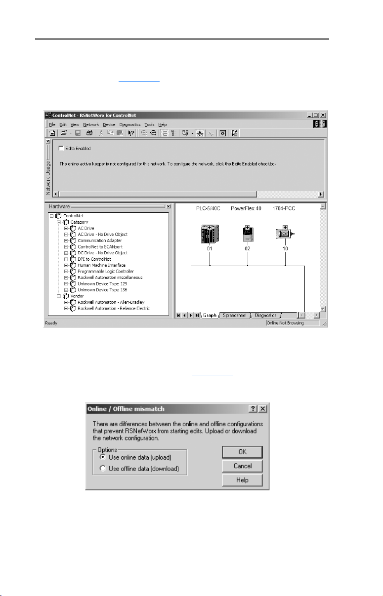
4. As the selected ControlNet path is browsed, RSNetWorx for
ControlNet creates a graphical representation of the devices on the
network (Figure 4.13
).
Figure 4.13 RSNetWorx for ControlNet Graph View Screen
Page 45

Configuring the I/O 4-11
5. Select Network > Enable Edits. If the bridge has a different I/O
configuration than the configuration now being saved, the Online /
Offline mismatch dialog box (Figure 4.14
Figure 4.14 Online / Offline mismatch Dialog Box
When both radio button choices are available, use the preselected
default “Use online data (upload).” When this choice is unavailable
(grayed out), you must select “Use offline data (download).” Then
click OK.
6. Select File > Save to save the I/O configuration file to the computer.
If this is the first time that you saved the project, the Save As dialog
box appears. Navigate to a folder, type a file name, and click Save to
save the configuration to a file on your computer. The Save
Configuration dialog box (Figure 4.15
download the I/O configuration to the bridge.
) will appear.
) appears. Then click OK to
Figure 4.15 Save Configuration Dialog Box
TIP: If both Save Type choices are available, it is
recommended to select the “Optimize and re-write schedule
for all connections” radio button.
Page 46
4-12 Configuring the I/O
PLC-5 Example
Example Network
After the adapter is configured, the connected drive and adapter will be a
single node on the network. This section provides the steps that are
needed to configure a simple network like the network in Figure 4.16. In
our example, we will configure a PLC-5/40C controller to communicate
with a drive using Logic Command/Status and Reference/Feedback over
the network.
Figure 4.16 Example ControlNet Network
Node 1
PLC-5/40C Controller
Node 2
PowerFlex 40 Drive
with 22-COMM-C
ControlNet Adapter
ControlNet Network
(optional redundancy)
Node 99
Computer with 1784-PCC
Network Interface Card and
RSNetWorx for ControlNet
Adding the Drive and Adapter I/O to the Controller
To establish an I/O configuration that can be used between the controller
and drive over a ControlNet network, you must first create an I/O image
for the PLC-5/40C controller’s built-in scanner.
1. Launch RSNetWorx for ControlNet. In the RSNetWorx for
ControlNet window, select File > New to display the New File
screen. Then select ControlNet Configuration as the network
configuration type, and click OK.
2. Select Network > Online to display the Browse for Network screen
(Figure 4.17
).
Page 47

Configuring the I/O 4-13
Figure 4.17 Browse for Network Screen
3. Expand the communications path from your computer to the
ControlNet scanner. Figure 4.18
devices that are on a ControlNet network. Depending on the
communication link you are using, the navigation path may be
different. After selecting a valid ControlNet path (for example, A,
ControlNet), click OK.
shows our example navigating to
Figure 4.18 Expanded Browse for Network Screen
Page 48
4-14 Configuring the I/O
4. As the selected ControlNet path is browsed, RSNetWorx for
ControlNet creates a graphical representation of the devices on the
network (Figure 4.19
Figure 4.19 RSNetWorx for ControlNet Graph View Screen
).
5. Select Network > Enable Edits. If the scanner has a different I/O
configuration than the configuration now being saved, the Online /
Offline mismatch dialog box (Figure 4.20
Figure 4.20 Online / Offline mismatch Dialog Box
) will appear.
When both radio button choices are available, use the preselected
default “Use online data (upload).” When this choice is unavailable
(grayed out), you must select “Use offline data (download).” Then
click OK.
Page 49

Configuring the I/O 4-15
6. In the RSNetWorx for ControlNet graph view screen, right-click the
PLC-5/40C icon and select Scanlist Configuration to display the
Scanlist Configuration screen (Figure 4.21
Figure 4.21 Scanlist Configuration Screen
7. Right-click on the PowerFlex 40 drive row in the screen and select
Insert Connection… to display the Connection Properties screen
(Figure 4.22
).
).
Figure 4.22 Connection Properties Screen
In this screen, leave the Connection Name box at the default value
shown. Choose a Requested Packet Interval that is suitable for your
application, but is at least 5 ms. Use the pull-down lists to select the
Page 50

4-16 Configuring the I/O
number of words that are required for your I/O in the Input Size and
Output Size boxes. The size will depend on the I/O that you enabled
in the adapter. This information can be found in Parameter 12 -
[DSI I/O Cfg] in the adapter. Table 4.B
configuration Input/Output sizes.
Table 4.B PLC-5/40C Input/Output Size Configurations
Input
Output
Size
Size
22 ✔✔Drive 0 Single
44 ✔✔Drives 0-1
66 ✔✔Drives 0-2
88 ✔✔Drives 0-3
10 10 ✔✔Drives 0-4
TIP: If necessary, the N9:0, N10:0, and N11:0 address
defaults can be changed to meet processor address
requirements or eliminate address conflicts.
8. Then click OK. An address row (in blue text) will be added below
the PowerFlex 40 drive row.
9. Select File > Save to save the I/O configuration file to the computer.
If this is the first time that you saved the project, the Save As dialog
box appears. Navigate to a folder, type a file name, and click Save to
save the configuration to a file on your computer. The Save
Configuration dialog box (Figure 4.23
download the I/O configuration to the scanner.
Logic Command/
Status
shows common
Reference/
Feedback
Parameter 12 [DSI I/O Cfg]
) appears. Then click OK to
Parameter 01 [Mode]
Multi-Drive
Figure 4.23 Save Configuration Dialog Box
TIP: If both Save Type choices are available, it is
recommended to select the “Optimize and re-write schedule
for all connections” radio button.
10. A warning will appear about communication and I/O disruption on
the network. Click Ye s .
Page 51

Chapter 5
Using the I/O
Chapter 5 provides information and examples that explain how to use the
I/O to control, configure, and monitor a PowerFlex 4-Class drive.
Topic Page
About I/O Messaging
Understanding the I/O Image 5-2
Using Logic Command/Status 5-3
Using Reference/Feedback 5-3
Example Ladder Logic Program Infor mation 5-4
ControlLogix Example 5-5
PLC-5 Example 5-8
ATTENTION: Risk of injury or equipment damage exists. The
examples in this publication are intended solely for purposes of
!
example. There are many variables and requirements with any
application. Rockwell Automation, Inc. does not assume responsibility
or liability (to include intellectual property liability) for actual use of
the examples shown in this publication.
5-1
About I/O Messaging
On ControlNet, I/O messaging is used to transfer the data which controls
the PowerFlex drive and sets its Reference.
The adapter provides many options for configuring and using I/O,
including configuring the size of I/O by selecting the number of attached
drives (Single or Multi-Drive mode).
Chapter 3
discuss how to configure the adapter and controller on the network for
these options. The Glossary defines the different options. This chapter
discusses how to use I/O after you have configured the adapter and
controller.
, Configuring the Adapter, and Chapter 4, Configuring the I/O,
Page 52

5-2 Using the I/O
Understanding the I/O Image
The terms input and output are defined from the controller’s point of
view. Therefore, output I/O is data that is produced by the controller and
consumed by the adapter. Input I/O is status data that is produced by the
adapter and consumed as input by the controller. The I/O image table
will vary based on the configuration of the adapter:
• Operating Mode Jumper J7 (Figure 2.1
• Parameter 12 - [DSI I/O Cfg]
The image table always uses consecutive words starting at word 0.
Figure 5.1
(16-bit words) for ControlLogix and PLC-5 controllers respectively.
Figure 5.1 Single Drive Example of I/O Image for ControlLogix
Controller
)
and Figure 5.2 illustrate examples of a Single drive I/O image
Scanner
Output
Image
(Write)
Input
Image
(Read)
ControlNet
Adapter
Word and I/O
0 Logic Command
1 Reference
0 Pad Word
1 Pad Word
2 Logic Status
3 Feedback
DSI
PowerFlex 40 Drive
Logic Command
Reference
Logic Status
Feedback
Message
Handler
Figure 5.2 Single Drive Example of I/O Image for PLC-5
ControlNet
Controller
Single mode is the typical configuration, where one node consists of a
PowerFlex 40 or PowerFlex 400 drive with a 22-COMM-C adapter. For
Multi-Drive mode, where one node can consist of up to 5 drives, refer to
Chapter 7
Scanner
Output
Image
(Write)
Input
Image
(Read)
Message
Handler
, Using Multi-Drive Mode.
Message
Buffer
Adapter
Word and I/O
0 Logic Command
1 Reference
0 Logic Status
1 Feedback
Message
Buffer
DSI
Message
Handler
PowerFlex 40 Drive
Logic Command
Reference
Logic Status
Feedback
Message
Handler
Page 53

Using the I/O 5-3
Using Logic Command/Status
The Logic Command word is always word 0 in the output image. The
Logic Command is a 16-bit word of control produced by the controller
and consumed by the adapter. The Logic Status word is input word 2 for
ControlLogix or input word 0 for PLC-5. The Logic Status is a 16-bit
word of status produced by the adapter and consumed by the controller.
This manual contains the bit definitions for compatible products
available at the time of publication in Appendix
Status Words. For other products, refer to their documentation.
Using Reference/Feedback
The Reference word is always word 1 in the output image. The
Reference (16 bits) is produced by the controller and consumed by the
adapter. The Feedback word begins at input word 3 for ControlLogix or
input word 1 for PLC-5. The Feedback (16 bits) is produced by the
adapter and consumed by the controller.
D, Logic Command/
Size Drive Valid Values
PowerFlex 4 -240.0 to +240.0 Hz
16-bit
(1)
PowerFlex 40 -400.0 to +400.0 Hz
PowerFlex 400 -320.00 to +320.00 Hz
The Reference/Feedback for a PowerFlex 4, PowerFlex 40 or Powerflex 400 drive is
set in Hz and not in engineering units like PowerFlex 7-Class drives. For example,
“300” equates to 30.0 Hz (the decimal point is always implied) for PowerFlex 4/40, and
“3000” equates to 30.00 Hz for PowerFlex 400. Also, a minus value equates to reverse
motor direction, and a plus value equates to forward motor direction.
(1)
Example
Figure 5.1
Figure 5.2
or
Page 54

5-4 Using the I/O
Example Ladder Logic Program Information
The example ladder logic programs in the ControlLogix Example and
PLC-5 Example sections of this chapter are intended for and operate
PowerFlex 4-Class drives.
Functions of the Example Programs
The example programs enable an operator to perform the following:
• Obtain status information from the drive.
• Use the Logic Command to control the drive (for example, start, stop).
• Send a Reference to the drive and receive Feedback from the drive.
Adapter Settings for the Example Programs
• Node address 2 is set using parameters.
• The adapter is configured for Single mode operation (Operating Mode
Jumper J7 is set to “1x”).
Scanner Settings for the ControlLogix Example Program
• The scanner is in slot 1 and is node 1 on the ControlNet network.
• Output to the adapter is mapped in word 0 and word 1, and input from
the adapter is in words 2 and 3 (0 and 1 are pad words).
Scanner Settings for the PLC-5 Example Program
• The scanner is node 1 on the ControlNet network.
• Output to the adapter is mapped in N10:0 and N10:1, and input from
the adapter is in N9:0 and N9:1.
Logic Command/Status Words
These examples use the Logic Command word and Logic Status word
for PowerFlex 40 drives. Refer to Appendix
Wor ds to view these. The definition of the bits in these words may vary if
you are using a different DSI product. Refer to the documentation for
your product.
D, Logic Command/Status
Page 55

Using the I/O 5-5
ControlLogix Example
The Drive I/O Control program (Figure 5.3) defines the I/O needed to
control the drive.
The following program tags are used for the Drive I/O Control Routine:
Tag Name Type Description
Status_Ready BOOL Ready bit
Status_Active BOOL Active bit
Status_Forward BOOL Forward bit
Status_Reverse BOOL Reverse bit
Status_Faulted BOOL Faulted bit
Status_At_Speed BOOL At speed bit
Speed_Feedback INT Speed feedback word
Command_Stop BOOL Stop bit
Command_Start BOOL Start bit
Command_Jog BOOL Jog bit
Command_Clear_Faults BOOL Clear faults bit
Command_Forward_Reverse BOOL Forward/reverse bit
Speed_Reference INT Speed reference word
Page 56

5-6 Using the I/O
Figure 5.3 ControlLogix Ladder Logic Example for Drive I/O Control
PowerFlex 40 ControlNet Single Mode Example
PowerFlex 40 ControlNet Single Mode Example
This ControlLogix example system consists of a 1756-CNBR/D in Slot 4 communicating on a ControlNet network with a
This ControlLogix example system consists of a 1756-CNBR/D in Slot 4 communicating on a ControlNet network with a
PowerFlex 40 drive with an installed 22-COMM-C ControlNet adapter. You may substitute the "PowerFlex 40" for a
PowerFlex 40 drive with an installed 22-COMM-C ControlNet adapter. You may substitute the "PowerFlex 40" for a
PowerFlex 400, or a PowerFlex 4 using an External DSI Communicaitons Kit (22-XCOMM-DC-BASE).
PowerFlex 400, or a PowerFlex 4 using an External DSI Communicaitons Kit (22-XCOMM-DC-BASE).
The I/O image is as follows:
The I/O image is as follows:
INPUT (4 INT words)
INPUT (4 INT words)
PowerFlex_40_Drive:I.Data[0] = 1756-CNBR Overhead (Not Used)
PowerFlex_40_Drive:I.Data[0] = 1756-CNBR Overhead (Not Used)
PowerFlex_40_Drive:I.Data[1] = 1756-CNBR Overhead (Not Used)
PowerFlex_40_Drive:I.Data[1] = 1756-CNBR Overhead (Not Used)
PowerFlex_40_Drive:I.Data[2] = PowerFlex 40 Logic Status
PowerFlex_40_Drive:I.Data[2] = PowerFlex 40 Logic Status
PowerFlex_40_Drive:I.Data[3] = PowerFlex 40 Speed Feedback
PowerFlex_40_Drive:I.Data[3] = PowerFlex 40 Speed Feedback
OUTPUT (2 INT words)
OUTPUT (2 INT words)
PowerFlex_40_Drive:O.Data[0] = PowerFlex 40 Logic Command
PowerFlex_40_Drive:O.Data[0] = PowerFlex 40 Logic Command
PowerFlex_40_Drive:O.Data[1] = PowerFlex 40 Speed Reference
PowerFlex_40_Drive:O.Data[1] = PowerFlex 40 Speed Reference
Logic Status information rungs are provided for display purposes only. The PowerFlex_40_Drive:I.Data[2].x bits could be
Logic Status information rungs are provided for display purposes only. The PowerFlex_40_Drive:I.Data[2].x bits could be
used directly elsewhere in the ladder program.
used directly elsewhere in the ladder program.
PowerFlex_40_Drive:I.Data[2].0
0
Status_Ready
PowerFlex_40_Drive:I.Data[2].1
1
PowerFlex_40_Drive:I.Data[2].3
2
PowerFlex_40_Drive:I.Data[2].3
3 /
PowerFlex_40_Drive:I.Data[2].7
4
PowerFlex_40_Drive:I.Data[2].8
5
This rung displays the Speed Feedback word from the PowerFlex 40. Note that it is set in Hz and not in engineering units
This rung displays the Speed Feedback word from the PowerFlex 40. Note that it is set in Hz and not in engineering units
like PowerFlex 7-Class drives. For example, "300" equates to 30.0 Hz (the decimal point is always implied).
like PowerFlex 7-Class drives. For example, "300" equates to 30.0 Hz (the decimal point is always implied).
6
Logic Command bit control rungs are provided for display purposes only. The PowerFlex_40_Drive:O.Data[0].x bits could be
Logic Command bit control rungs are provided for display purposes only. The PowerFlex_40_Drive:O.Data[0].x bits could be
used directly elsewhere in the ladder program.
used directly elsewhere in the ladder program.
Command_Stop
7
Command_Start
8
Move
Source PowerFlex_40_Drive:I.Data[3]
0
Dest Speed_Feedback
0
PowerFlex_40_Drive:O.Data[0].0
PowerFlex_40_Drive:O.Data[0].1
Status_Reverse
Status_At_Speed
MOV
Status_Active
Status_Forward
Status_Faulted
Page 57

Using the I/O 5-7
Figure 5.3 ControlLogix Ladder Logic Example for Drive I/O Control (Continued)
Command_Jog
9
Command_Clear_Faults
10
Command_Forward_Reverse
11
Command_Forward_Reverse
12 /
This rung provides the Speed Reference word to the PowerFlex 40. Note that it is set in Hz and not in engineering units like
This rung provides the Speed Reference word to the PowerFlex 40. Note that it is set in Hz and not in engineering units like
PowerFlex 7-Class drives. For example, "300" equates to 30.0 Hz (the decimal point is always implied).
PowerFlex 7-Class drives. For example, "300" equates to 30.0 Hz (the decimal point is always implied).
13
(End)
PowerFlex_40_Drive:O.Data[0].2
PowerFlex_40_Drive:O.Data[0].3
PowerFlex_40_Drive:O.Data[0].4
PowerFlex_40_Drive:O.Data[0].5
Move
Source Speed_Reference
600
Dest PowerFlex_40_Drive:O.Data[1]
0
MOV
For a ControlLogix controller explicit message ladder example program,
see Figure 6.4
.
Page 58

5-8 Using the I/O
PLC-5 Example
The Drive I/O Control program (Figure 5.4) defines the I/O needed to
control the drive.
Figure 5.4 PLC-5 Ladder Logic Example for Drive I/O Control
In this example, an operator station is wir ed into the local PLC-5/40C rack as fol lows:
O:000/0 Drive Ready
O:000/1 Drive Active
O:000/2 Drive Forward
O:000/3 Drive Reverse
O:000/4 Drive Faulted
O:000/5 Drive At Speed
O:001 Operator Speed Feedback
I:000/0 Stop (Normally
I:000/1 Start (Normally Open Pushbutton)
I:000/2 Jog (Normally Open Pushbutton)
I:000/3 Clear Faults (Normally Open Pushbutton)
I:000/4 Forward / Reverse Selector Switch
I:001 Operator Speed Reference
In this example, a PowerFlex 40 drive with instal led 22-COMM-C ControlNet adapter is mapped as follows:
N9:0 Logic Status N10:0 Logic Command
N9:1 Speed Feedback N10:1 Speed Reference
Rungs 0000 through 0005 move the Logic Status fr om the drive to the operator st ation.
Drive Logic Status
READY
0000
0001
0002
0003
0004
0005
N9:0
0
Drive Logic Status
ACTIVE
N9:0
1
Drive Logic Status
ACTUAL FORWARD /
REVERSE DIRECTION
Drive Logic Status
ACTUAL FORWARD /
REVERSE DIRECTION
Drive Logic Status
FAULTED
N9:0
7
Drive Logic Status
AT SPEED
N9:0
8
Open Pushbutton)
N9:0
3
N9:0
3
Operator
Drive Ready Status
Display
O:000
0
Operator
Drive Active Status
Display
O:000
1
Operator
Drive Actual Forward
Status Display
O:000
2
Operator
Drive Actual Reverse
Status Display
O:000
3
Operator
Drive Fault Status
Display
O:000
4
Operator
Drive At Speed
Status Display
O:000
5
Page 59

Using the I/O 5-9
Figure 5.4 PLC-5 Ladder Logic Example for Drive I/O Control (Continued)
Rung 0006 moves the Speed Feedback from the drive to the operator s tation.
0006
Rungs 0007 through 0012 move the Logic Command from the operator stati on to the drive.
Operator
Stop Pushbutton
0007
0008
0009
0010
0011
0012
0013
I:000
0
Operator
Start Pushbutton
I:000
1
Operator
Jog Pushbutton
I:000
2
Operator
Clear Faults
Pushbutton
I:000
3
Operator
Forward / Reverse
Selector Switch
I:000
4
Operator
Forward / Reverse
Selector Switch
I:000
4
Rung 0013 moves the Speed Reference from the operator st ation to the drive.
Drive
Speed Feedback
MOV
MOV
Move
Source N9:1
0<
Dest O:001
0<
Drive Logic Command
STOP
N10:0
0
Drive Logic Command
START
N10:0
1
Drive Logic Command
JOG
N10:0
2
Drive Logic Command
CLEAR FAULTS
N10:0
3
Drive Logic Command
FORWARD
N10:0
4
Drive Logic Command
REVERSE
N10:0
5
Drive
Speed Reference
MOV
MOV
Move
Source I:001
0<
Dest N10:1
0<
0014
END
For a PLC-5 controller explicit message ladder example program, see
Figure 6.5
.
Page 60

5-10 Using the I/O
Notes:
Page 61

Chapter 6
Using Explicit Messaging
Chapter 6 provides information and examples that explain how to use
Explicit Messaging to configure and monitor the 22-COMM-C adapter
and PowerFlex 4-Class drive to which it is connected.
Topic Page Topic Page
About Explicit Messaging
Performing Explicit Messages 6-2 PLC-5 Example 6-6
ATTENTION: Risk of injury or equipment damage exists. The
examples in this publication are intended solely for purposes of
!
example. There are many variables and requirements with any
application. Rockwell Automation, Inc. does not assume responsibility
or liability (to include intellectual property liability) for actual use of
the examples shown in this publication.
ATTENTION: Risk of equipment damage exists. If Explicit Messages
are programmed to write parameter data to Non-Volatile Storage (NVS)
!
frequently, the NVS will quickly exceed its life cycle and cause the
drive to malfunction. Do not create a program that frequently uses
Explicit Messages to write parameter data to NVS.
6-1 ControlLogix Example 6-3
Refer to Chapter 5 for information about the I/O image, using Logic
Command/Status and Reference/Feedback.
About Explicit Messaging
Explicit Messaging is used to transfer data that does not require
continuous updates. With Explicit Messaging, you can configure and
monitor a slave device’s parameters on the ControlNet network.
Important: When an explicit message is performed, by default no I/O
connection is made since it is an “unconnected” message.
When timing of the message transaction is important, you
can create a dedicated message connection between the
controller and drive by checking the “Connected” box on
the Communications tab message configuration screen
Page 62

6-2 Using Explicit Messaging
during message setup. These message connections are in
addition to the I/O connection. However, the tradeoff for
more message connections is decreased network
performance. If your application cannot tolerate this, do not
check the “Connected” box.
Performing Explicit Messages
There are five basic events in the Explicit Messaging process. The details
of each step will vary depending on the type of controller being used.
Refer to the documentation for your controller.
Important: There must be a request message and a response message
for all Explicit Messages, whether you are reading or
writing data.
Figure 6.1 Explicit Message Process
Complete Explicit
➎
➍
Message
Retrieve Explicit
Message Response
Set up and send Explicit
➊
Message Request
➋
➌
Event
1. You format the required data and set up the ladder logic program to
send an Explicit Message request to the scanner or bridge module
(download).
2. The scanner or bridge module transmits the Explicit Message
Request to the slave device over the ControlNet network.
3. The slave device transmits the Explicit Message Response back to
the scanner or bridge. The data is stored in the scanner buffer.
4. The controller retrieves the Explicit Message Response from the
scanner’s buffer (upload).
5. The Explicit Message is complete. Note: When using a PLC-5
controller, delete the transaction ID so that it can be reused.
For information on the maximum number of Explicit Messages that can
be executed at a time, refer to the user manual for the bridge or scanner
and/or controller that is being used.
Page 63

Using Explicit Messaging 6-3
ControlLogix Example
TIP: To display the Message Configuration screen in RSLogix 5000,
add a message instruction (MSG), create a new tag for the message
(Properties: Base tag type, MESSAGE data type, controller scope), and
click the button in the message instruction.
Formatting a Message to Read a Parameter
A Get Attribute Single message is used to read a single parameter. This
example read message is for parameter d003 - [Output Current] for a
PowerFlex 4-Class drive.
Figure 6.2 Get Attribute Single Message Configuration Screens
Configuration Tab Example Value Description
Message Type
Service Type
Service Code
Class
Instance
Attribute
Destination
Communication Tab Example Value Description
(2)
Path
(1)
The default setting for Service Type is “Custom,” enabling entry of a Service Code not available from the Service
Type pull-down menu. When selecting a Service Type other than “Custom” from the pull-down menu, an
appropriate Hex. value is automatically assigned to the Service Code box which grays out (unavailable).
(2)
Click Browse to find the path, or type in the name of the device listed in the I/O Configuration folder.
CIP Generic
(1)
Get Attribute Single
(1)
e (Hex.)
f (Hex.)
3 (Dec.)
1 (Hex.)
Output_Current
PowerFlex_40… The path is the route that the message will follow.
CIP messages are used to access the Parameter object
in the 22-COMM-C.
This service is used to read a parameter value.
The code for the requested service.
The Class ID for the CIP Parameter object.
The instance number is the same as the parameter
number in Single mode operation.
The attribute number for the Parameter Value attribute.
The tag where the data that is read is stored.
Page 64

6-4 Using Explicit Messaging
For supported classes, instances, and attributes, refer to Appendix C,
ControlNet Objects
Formatting a Message to Write to a Parameter
A Set Attribute Single message is used to write to a single parameter.
This example write message is for parameter P039 - [Accel Time 1] for a
PowerFlex 4-Class drive.
Figure 6.3 Set Attribute Single Message Configuration Screens
.
Configuration Tab Example Value Description
Message Type
Service Type
Service Code
Class
Instance
Attribute
Source Element
Source Length
Communication Tab Example Value Description
(2)
Path
(1)
The default setting for Service Type is “Custom,” enabling entry of a Service Code not available from the Service
Type pull-down menu. When selecting a Service Type other than “Custom” from the pull-down menu, an
appropriate Hex. value is automatically assigned to the Service Code box which grays out (unavailable).
(2)
Click Browse to find the path, or type in the name of the device listed in the I/O Configuration folder.
For supported classes, instances, and attributes, refer to Appendix C,
ControlNet Objects
CIP Generic
(1)
Set Attribute Single
(1)
10 (Hex.)
f (Hex.)
39 (Dec.)
1 (Hex.)
Accel_Time_1
2 bytes
PowerFlex_40… The path is the route that the message will follow.
CIP messages are used to access the Parameter object
in the 22-COMM-C.
This service is used to write a parameter value.
The code for the requested service.
The Class ID for the CIP Parameter object.
The instance number is the same as the parameter
number in Single mode operation.
The attribute number for the Parameter Value attribute.
The tag where the data that is written is stored.
The size of a parameter value in a PowerFlex 4-Class
drive is always 2 bytes.
.
Page 65

Using Explicit Messaging 6-5
Table 6.A Tags for the ControlLogix Example Explicit Messaging Program
Tag N ame s
for Read Message Type
Perform_Parameter_Read BOOL Perform_Parameter_Write BOOL
Parameter_Read_Message MESSAGE Parameter_Write_Message MESSAGE
Output_Current INT Accel_Time_1 INT
Tag N ame s
for Write Message Type
Ladder Logic Program
Figure 6.4 Example ControlLogix Ladder Logic Explicit Messaging Program
Explicit Messaging Examples
Explicit Messaging Examples
Reading a single parameter (Get Attribute Single command)
Reading a single parameter (Get Attribute Single command)
This message example reads from Parameter d003 - [Output Current] and stores its value in the "Output_Current" controller
This message example reads from Parameter d003 - [Output Current] and stores its value in the "Output_Current" controller
tag.
tag.
Perform_Parameter_Read
0
Writing a single parameter (Set Attribute Single command)
Writing a single parameter (Set Attribute Single command)
This message example writes to Parameter P039 - [Accel Time 1] and stores its value in the "Accel_Time_1" controller tag.
This message example writes to Parameter P039 - [Accel Time 1] and stores its value in the "Accel_Time_1" controller tag.
1
Perform_Parameter_Write
Type - CIP Generic
Message Control Parameter_Read_Message
Type - CIP Generic
Message Control Parameter_Write_Message
MSG
MSG
EN
DN
...
ER
EN
DN
...
ER
(End)
For a ControlLogix controller I/O ladder example program, see
Figure 5.3
.
Page 66

6-6 Using Explicit Messaging
PLC-5 Example
Important: Due to controller limitations, explicit messaging can only
be performed on drive parameters up to Parameter 256.
The ControlNet I/O Transfer (CIO) instruction is used for PLC-5
controllers to send explicit messages.
Formatting a Message to Read a Parameter
This read message example is for parameter d003 - [Output Current] for
a PowerFlex 4-Class drive.
Configuration Box Example Value Description
Communication
Command
Service Code
Class Number
Instance Number
Attribute Number
PLC-5 Data Table
Address
Size in Elements
Por t Numb er
Local ControlNet Node
CIP Generic
e (Hex.)
f (Hex.)
3 (Hex.)
1 (Hex.)
N7:2
1
2
2
For supported classes, instances, and attributes, refer to Appendix
ControlNet Objects
CIP messages are used to access the Parameter object in
the 22-COMM-C.
The code for the Get_Attribute_Single service.
The Class ID for the CIP Parameter object.
The instance number is the same as the parameter number
in Single mode operation.
The attribute number for the Parameter Value attribute.
The user-defined address for any response service data
received by the controller.
The number of elements in the response data.
The channel on the PLC-5 used for the ControlNet network.
The node address of the 22-COMM-C adapter.
.
C,
Page 67

Formatting a Message to Write to a Parameter
This write message example is for parameter P039 - [Accel Time 1] for a
PowerFlex 4-Class drive.
Configuration Box Example Value Description
Communication
Command
Service Code
Class Number
Instance Number
Attribute Number
PLC-5 Data Table
Address
Size in Elements
Por t Numb er
Local ControlNet Node
CIP Generic
10 (Hex.)
f (Hex.)
27 (Hex.)
1 (Hex.)
N7:3
1
2
2
CIP messages are used to access the Parameter object in
the 22-COMM-C.
The code for the Set_Attribute_Single service.
The Class ID for the CIP Parameter object.
The instance number is the same as the parameter number
in Single mode operation.
The attribute number for the Parameter Value attribute.
The user-defined address for any request service data sent
by the controller.
The number of elements in the request data.
The channel on the PLC-5 used for the ControlNet network.
The node address of the 22-COMM-C adapter.
Using Explicit Messaging 6-7
For supported classes, instances, and attributes, refer to Appendix
ControlNet Objects.
C,
Page 68

6-8 Using Explicit Messaging
Ladder Logic Program
Figure 6.5 Example PLC-5 Ladder Logic Explicit Messaging Program
Rung 0000 enables the user to initiate an explicit message to read from Parameter d003 [Output
Current] in the drive.
Initiate Explicit
Message Parameter
Read
0000
Rung 0001 enables the user to initiate an explicit message to write to Parameter P039 [Accel
Time 1] in the drive.
0001
0002
B3:0
0
Initiate Explicit
Message Parameter
Write
B3:0
1
For a PLC-5 controller I/O ladder example program, see Figure 5.4.
Explicit Message
Parameter Read
CIO
CIO
ControlNet I/O Transfer
Control CT12:0
Setup Screen
Explicit Message
Parameter Write
CIO
CIO
ControlNet I/O Transfer
Control CT12:1
Setup Screen
EN
DN
ER
EN
DN
ER
END
Page 69

Chapter 7
Using Multi-Drive Mode
Chapter 7 provides information on how to use Multi-Drive mode and
includes ControlLogix and PLC-5 ladder examples.
Topic Page
Single Mode vs. Multi-Drive Mode
System Wiring 7-4
Understanding the I/O Image 7-5
Configuring the RS-485 Network 7-7
Example Configuration Settings 7-8
ControlLogix I/O Example 7-9
ControlLogix Explicit Messaging 7-22
PLC-5 I/O Example 7-24
Additional Information 7-36
7-1
ATTENTION: Risk of injury or equipment damage exists. The
examples in this publication are intended solely for purposes of
!
example. There are many variables and requirements with any
application. Rockwell Automation, Inc. does not assume responsibility
or liability (to include intellectual property liability) for actual use of
the examples shown in this publication.
Single Mode vs. Multi-Drive Mode
Single mode is a typical network installation, where a single ControlNet
node consists of a single drive with a 22-COMM-C adapter (Figure 7.1
).
Page 70

7-2 Using Multi-Drive Mode
Figure 7.1 Single Mode Example for Network
ControlNet Network
PowerFlex 40 or 400 Drive
with 22-COMM-C Adapter
Multi-Drive mode is an alternative to the typical network installation,
where a single ControlNet node can consist of one to five drives. In
Figure 7.2
PowerFlex 40/400 drive, and the remaining PowerFlex 4-Class drives are
daisy-chained from the RS-485 port on the first drive. In Figure 7.3, the
22-COMM-C adapter is externally mounted in a DSI External Comms
Kit, and all PowerFlex 4-Class drives are daisy-chained from it.
Figure 7.2 Multi-Drive Mode Example for Network - PowerFlex 40 Mounting
Terminating Resistor
, the 22-COMM-C adapter is internally mounted in a
ControlNet Network
PowerFlex 40
or 400 Drive
AK-U0-RJ45-TB2P
Connector with
1 drive per node
PowerFlex 40 or 400 Drive
with 22-COMM-C Adapter
up to 5 drives per node
Up to 4 Additional PowerFlex 4-Class Drives
22-COMM-C
Adapter
AK-U0-RJ45-TB2PRS-485
PowerFlex 40 or 400 Drive
with 22-COMM-C Adapter
AK-U0-RJ45-TB2P
Connector with
Terminating Resistor
Figure 7.3 Multi-Drive Mode Example for Network - External Comms Kit Mounting
ControlNet Network
DSI External Comms Kit
(22-XCOMM-DC-BASE)
NOTE: A terminating resistor
is not required for this end of
of the wiring. The resistor is
built into the circuitry of the
DSI External Comms Kit.
up to 5 drives per node
PORT
MOD
NET A
NET B
22-COMM-C
Adapter
Up to 5 PowerFlex 4-Class Drives
AK-U0-RJ45-TB2PRS-485
AK-U0-RJ45-TB2P
Connector with
Terminating Resistor
Page 71

Using Multi-Drive Mode 7-3
Benefits of Multi-Drive mode include:
• Lower hardware costs. Only one adapter is needed for up to five
drives. Any PowerFlex 4-Class drive can be daisy-chained.
• Reduces the network node count. For example, in Single mode 30
drives would consume 30 nodes. In Multi-Drive mode, 30 drives can
be connected in 6 nodes.
• Provides a convenient way to put more than one PowerFlex 4 drive on
the network using only one adapter (PowerFlex 4 drives do not have
an internal communications adapter slot).
• Controller can control, monitor, and read/write parameters for all five
drives.
Trade-offs of Multi-Drive mode include:
• When a PowerFlex 40/400 drive with an internal-mounted adapter is
powered down, communications with the daisy-chained drives is
disrupted and the drives will take the appropriate communications
loss action set in each drive. However, communications will not be
disrupted when the adapter is used in a DSI External Comms Kit and
a daisy-chained drive is powered down.
• Communications throughput to the daisy-chained drives will be
slower than if each drive was a separate node on the network (Single
mode). This is because the adapter must take the network data for the
other drives and sequentially send the respective data to each drive
over RS-485. The approximate additional throughput time for Logic
Command/Reference to be transmitted and received by each drive in
Multi-Drive mode is:
Adapter Mounted In
PowerFlex 40/400 or
DSI External Comms
Kit
• Since the RS-485 ports are used for daisy-chaining the drives, there is
no connection for a peripheral device such as a HIM. The
AK-U0-RJ45-SC1 DSI Splitter cable cannot be used to add a second
connection for a peripheral device.
Drives per
Node
1 drive 0 milliseconds
2 drives +24 milliseconds
3 drives +48 milliseconds
4 drives +72 milliseconds
5 drives +96 milliseconds
Additional Throughput
Time versus Single Mode
Page 72

7-4 Using Multi-Drive Mode
System Wiring
The AK-U0-RJ45-TB2P two-position terminal block connector
(Figure 7.4) can be used to conveniently daisy-chain the PowerFlex
4-Class drives. Two terminating resistors are also included with terminal
block connectors in the AK-U0-RJ45-TB2P kit.
Figure 7.4 AK-U0-RJ45-TB2P Terminal Block Connector
Figure 7.5 and Figure 7.6 show wiring diagrams for using the
AK-U0-RJ45-TB2P terminal block connectors.
Figure 7.5 Connector Wiring Diagram - Adapter Mounted in PowerFlex 40/400
To PowerFlex 40 or PowerFlex 400 Drive
(with 22-COMM-C adapter)
To
Ω
120
¼ Watt
Resistor
Figure 7.6 Connector Wiring Diagram - Adapter Mounted in DSI External Comms Kit
To DSI External Comms Kit
(with 22-COMM-C adapter)
NOTE: A terminating resistor
is not required for this end of
of the wiring. The resistor is
built into the circuitry of the
DSI External Comms Kit.
Drive 1
To
Drive 0
To
Drive 1
To
Drive 2
Drive 2
To
To
Drive 3
Drive 3
To
To
Drive 4
120
¼ Watt
Resistor
To
Drive 4
Ω
Ω
120
¼ Watt
Resistor
Page 73
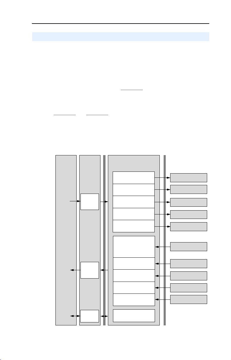
Using Multi-Drive Mode 7-5
Understanding the I/O Image
The terms input and output are defined from the scanner’s point of view.
Therefore, output I/O is data that is output from the scanner and
consumed by the adapter. Input I/O is status data that is produced by the
adapter and consumed as input by the scanner. The I/O image table will
vary based on the configuration of the adapter:
• Operating Mode Jumper J7 (Figure 2.1
• Parameter 12 - [DSI I/O Cfg]
The image table always uses consecutive words starting at word 0.
Figure 7.7
image with 16-bit words for ControlLogix and PLC-5 controllers
respectively.
Figure 7.7 Multi-Drive Example of I/O Image for ControlLogix
Controller
and Figure 7.8 illustrate examples of the Multi-Drive I/O
ControlNet
Scanner
or
Bridge
Output
Image
(Write)
Input
Image
(Read)
Word and I/O
0 Logic Command
1 Reference
2 Logic Command
3 Reference
4 Logic Command
5 Reference
6 Logic Command
7 Reference
8 Logic Command
9 Reference
0 Pad Word
1 Pad Word
2 Logic Status
3 Feedback
4 Logic Status
5 Feedback
6 Logic Status
7 Feedback
8 Logic Status
9 Feedback
10 Logic Status
11 Feedback
)
DSI
Adapter
PowerFlex Drive 0
Power Flex Dr ive 1
PowerFlex Drive 2
PowerFlex Drive 3
PowerFlex Drive 4
PowerFlex Drive 0
PowerFlex Drive 1
PowerFlex Drive 2
Power Flex Dr ive 3
PowerFlex Drive 4
Message
Handler
Message
Buffer
Page 74

7-6 Using Multi-Drive Mode
Figure 7.8 Multi-Drive Example of I/O Image for PLC-5
Controller
Scanner
or
Bridge
Output
Image
(Write)
Input
Image
(Read)
Message
Handler
ControlNet
Adapter
Word and I/O
0 Logic Command
1 Reference
2 Logic Command
3 Reference
4 Logic Command
5 Reference
6 Logic Command
7 Reference
8 Logic Command
9 Reference
0 Logic Status
1 Feedback
2 Logic Status
3 Feedback
4 Logic Status
5 Feedback
6 Logic Status
7 Feedback
8 Logic Status
9 Feedback
Message
Buffer
DSI
PowerFlex Drive 0
Power Flex Dr ive 1
PowerFlex Drive 2
PowerFlex Drive 3
PowerFlex Drive 4
PowerFlex Drive 0
PowerFlex Drive 1
PowerFlex Drive 2
Power Flex Dr ive 3
PowerFlex Drive 4
Note: If a daisy-chained drive is disconnected from the RS-485 (DSI)
network or powered down, the Logic Status and Feedback words for the
affected drive will be set to 0.
Page 75

Using Multi-Drive Mode 7-7
Configuring the RS-485 Network
The following parameters in each daisy-chained drive must be set to
these values:
Parameter Value
P36 - [Start Source] 5 (Comm Port)
P38 - [Speed Reference] 5 (Comm Port)
A103 - [Comm Data Rate] 4 (19.2K)
A104 - [Comm Node Addr] 1-247 (must be unique)
A107 - [Comm Format] 0 (RTU 8-N-1)
Note that the RS-485 network is fixed at 19.2K baud, 8 data bits, no
parity, and 1 stop bit.
Important: Parameter A105 - [Comm Loss Action] in the drives that
are daisy chained is still used in Multi-Drive mode. If the
RS-485 cable is disconnected or broken, the disconnected
drive(s) will immediately take the corresponding Comm
Loss Action(s). Drive parameter A106 - [Comm Loss
Time] is not used in Multi-Drive mode. For a network
disruption, adapter Parameters 08 - [Comm Flt Action]
and 09 - [Idle Flt Action] determine the action taken for
ALL of the drives on the Multi-Drive node.
The following Multi-Drive parameters must be set in the 22-COMM-C:
Parameter Value
12 - [DSI I/O Cfg] 0 = Drive 0 connected
14 - [Drv 0 Addr] Equal to Drive 0 parameter A104 - [Comm Node Address]
15 - [Drv 1 Addr] Equal to Drive 1 parameter A104 - [Comm Node Address]
16 - [Drv 2 Addr] Equal to Drive 2 parameter A104 - [Comm Node Address]
17 - [Drv 3 Addr] Equal to Drive 3 parameter A104 - [Comm Node Address]
18 - [Drv 4 Addr] Equal to Drive 4 parameter A104 - [Comm Node Address]
After setting the 22-COMM-C parameters, set the Operating Mode
Jumper (J7) from “1x” (Single mode) to “5x” (Multi-Drive) operation,
and reset the adapter or cycle power to invoke the change. Refer to
Setting Operating Mode and Node Address Switches
Important: The 22-COMM-C parameters can be set using a DSI
peripheral (HIM, DriveExplorer with 22-SCM-232, etc.)
ONLY when the Operating Mode Jumper is in the “1x”
(Single mode) position.
1 = Drives 0-1 connected
2 = Drives 0-2 connected
3 = Drives 0-3 connected
4 = Drives 0-4 connected
on page 2-1.
Page 76

7-8 Using Multi-Drive Mode
Example Configuration Settings
Adapter Settings
• The adapter Operating Mode Jumper (J7 in Figure 2.1) is set to the
“5x” (Multi-Drive) position.
• The 22-COMM-C adapter parameters are set as follows:
Parameter Value Description
12 - [DSI I/O Cfg] 4 “Drives 0-4” (5 drives on 1 node)
14 - [Drv 0 Addr]
15 - [Drv 1 Addr]
16 - [Drv 2 Addr]
17 - [Drv 3 Addr]
18 - [Drv 4 Addr]
(1)
The settings for these parameters must match the parameter A104 - [Comm Node
Addr] settings in the respective drives.
(1)
(1)
(1)
(1)
(1)
Drive Settings
Parameters for the five drives are set as follows:
1 Address of Drive 0
2 Address of Drive 1
3 Address of Drive 2
4 Address of Drive 3
5 Address of Drive 4
Parameter
P36 - [Start Source] 5 5 5 5 5
P38 - [Speed Reference] 5 5 5 5 5
A103 - [Comm Data Rate]
A104 - [Comm Node Addr]
A105 - [Comm Loss Action] 0 0 0 0 0
A106 - [Comm Loss Time] 5 5 5 5 5
A107 - [Comm Format]
(1)
The drive must be reset for a change to this parameter to take effect.
(2)
The settings for these parameters must match the respective parameter settings in the
adapter (Parameter 14 - [Drv 0 Addr] through Parameter 18 - [Drv 4 Addr]).
Drive 0 Drive 1 Drive 2 Drive 3 Drive 4
(1)
44444
(1)(2)
12345
(1)
00000
Val ue
Page 77

Using Multi-Drive Mode 7-9
ControlLogix I/O Example
This example ladder logic program demonstrates using Multi-Drive
mode with five drives. See Figure 7.2 or Figure 7.3 for a system layout
diagram.
Function of the Example Program
This example program enables you to:
• View status information from the drives such as Ready, Faulted, At
Speed, and Feedback.
• Control the drives using various Logic Command bits (Stop, Start,
etc.) and Reference.
• Perform a single parameter read of drive parameter d003 - [Output
Current] and a single parameter write to drive parameter P039 [Accel Time 1].
Main Routine
The Main Routine reads the network Input Image from the scanner,
initiates Drive 0 through Drive 4 control subroutines, and writes the
network Output Image to the scanner. See Figure 7.9. The Generic
Controller Module is configured for an Input Size of 12 words and an
Output Size of 10 words. For additional information about I/O
connection sizes, see Table 4.A
.
The following controller tags are used:
Tag Name Type Description
Drive_Input_Image INT [10] Input Image Table
Drive_Output_Image INT [10] Output Image Table
Page 78

7-10 Using Multi-Drive Mode
_
_
Figure 7.9 ControlLogix Main Routine
PowerFlex 40 ControlNet Multi-Drive Mode Example
PowerFlex 40 ControlNet Multi-Drive Mode Example
ControlLogix Multi-Drive Mode example program with a PowerFlex 40 on ControlNet (22-COMM-C adapter). In this example,
ControlLogix Multi-Drive Mode example program with a PowerFlex 40 on ControlNet (22-COMM-C adapter). In this example,
Four (4) PowerFlex 4 drives are daisy-chained to the main PowerFlex 40 (with installed 22-COMM-C adapter) via their RJ-45
Four (4) PowerFlex 4 drives are daisy-chained to the main PowerFlex 40 (with installed 22-COMM-C adapter) via their RJ-45
ports (RS-485). In this mode, a total of up to five (5) PowerFlex 4/40/400's can exist as one (1) ControlNet node on the
ports (RS-485). In this mode, a total of up to five (5) PowerFlex 4/40/400's can exist as one (1) ControlNet node on the
network.
network.
This rung retrieves the Logic Status and Speed Feedback data for all five (5) drives from the scanner (array of INTs), and
This rung retrieves the Logic Status and Speed Feedback data for all five (5) drives from the scanner (array of INTs), and
moves them to specific INT tags for use elsewhere in the ladder program. The input image is as follows:
moves them to specific INT tags for use elsewhere in the ladder program. The input image is as follows:
Drive_Input_Image[0] and Drive_Input_Image[1] = Drive 0 Logic Status and Speed Feedback
Drive_Input_Image[0] and Drive_Input_Image[1] = Drive 0 Logic Status and Speed Feedback
Drive_Input_Image[2] and Drive_Input_Image[3] = Drive 1 Logic Status and Speed Feedback
Drive_Input_Image[2] and Drive_Input_Image[3] = Drive 1 Logic Status and Speed Feedback
Drive_Input_Image[4] and Drive_Input_Image[5] = Drive 2 Logic Status and Speed Feedback
Drive_Input_Image[4] and Drive_Input_Image[5] = Drive 2 Logic Status and Speed Feedback
Drive_Input_Image[6] and Drive_Input_Image[7] = Drive 3 Logic Status and Speed Feedback
Drive_Input_Image[6] and Drive_Input_Image[7] = Drive 3 Logic Status and Speed Feedback
Drive_Input_Image[8] and Drive_Input_Image[9] = Drive 4 Logic Status and Speed Feedback
Drive_Input_Image[8] and Drive_Input_Image[9] = Drive 4 Logic Status and Speed Feedback
0
Drive 0 control subroutine.
Drive 0 control subroutine.
1
Drive 1 control subroutine.
Drive 1 control subroutine.
2
Drive 2 control subroutine.
Drive 2 control subroutine.
3
Copy File
Source
Dest Drive_Input_Image[0]
Length 10
COP
5_PowerFlex_4_Class_Drives:I.Data[2]
JSR
Jump To Subroutine
Routine Name Drive_0
JSR
Jump To Subroutine
Routine Name Drive_1
JSR
Jump To Subroutine
Routine Name Drive_2
Drive 3 control subroutine.
Drive 3 control subroutine.
4
Drive 4 control subroutine.
Drive 4 control subroutine.
5
This rung writes the output image to the scanner. The output image is as follows:
This rung writes the output image to the scanner. The output image is as follows:
Drive_Output_Image[0] and Drive_Output_Image[1] = Drive 0 Logic Command and Speed Reference
Drive_Output_Image[0] and Drive_Output_Image[1] = Drive 0 Logic Command and Speed Reference
Drive_Output_Image[2] and Drive_Output_Image[3] = Drive 1 Logic Command and Speed Reference
Drive_Output_Image[2] and Drive_Output_Image[3] = Drive 1 Logic Command and Speed Reference
Drive_Output_Image[4] and Drive_Output_Image[5] = Drive 2 Logic Command and Speed Reference
Drive_Output_Image[4] and Drive_Output_Image[5] = Drive 2 Logic Command and Speed Reference
Drive_Output_Image[6] and Drive_Output_Image[7] = Drive 3 Logic Command and Speed Reference
Drive_Output_Image[6] and Drive_Output_Image[7] = Drive 3 Logic Command and Speed Reference
Drive_Output_Image[8] and Drive_Output_Image[9] = Drive 4 Logic Command and Speed Reference
Drive_Output_Image[8] and Drive_Output_Image[9] = Drive 4 Logic Command and Speed Reference
(Note the length of the COP instruction is "10" because the Destination address is an INT)
(Note the length of the COP instruction is "10" because the Destination address is an INT)
6
(End)
Copy File
Source Drive_Output_Image[0]
5_PowerFlex_4_Class_Drives:O.Data[0]
Dest
Length 10
JSR
Jump To Subroutine
Routine Name Drive_3
JSR
Jump To Subroutine
Routine Name Drive_4
COP
Page 79

Using Multi-Drive Mode 7-11
Drive 0 - Drive 4 Control Subroutines
The following Drive Control subroutines provide status information
(Logic Status and Feedback), control (Logic Command and Reference),
and parameter read/write for each of the respective drives:
Control Subroutine Refer to…
Drive 0 Figure 7.10
Drive 1 Figure 7.11
Drive 2 Figure 7.12
Drive 3 Figure 7.13
Drive 4 Figure 7.14
The following program tags are used for the Drive 0 Control Subroutine:
Tag Name Type Description
Drive_0_Status_Ready BOOL Drive 0 ready bit
Drive_0_Status_Active BOOL Drive 0 active bit
Drive_0_Status_Forward BOOL Drive 0 forward bit
Drive_0_Status_Reverse BOOL Drive 0 reverse bit
Drive_0_Status_Faulted BOOL Drive 0 faulted bit
Drive_0_Status_At_Speed BOOL Drive 0 at speed bit
Drive_0_Speed_Feedback INT Drive 0 speed feedback word
Drive_0_Command_Stop BOOL Drive 0 stop bit
Drive_0_Command_Start BOOL Drive 0 start bit
Drive_0_Command_Jog BOOL Drive 0 jog bit
Drive_0_Command_Clear_Faults BOOL Drive 0 clear faults bit
Drive_0_Command_Forward_Reverse BOOL Drive 0 forward/reverse bit
Drive_0_Speed_Reference INT Drive 0 speed reference word
Drive_0_Parameter_Read_Message MESSAGE Get_Attribute_Single (Read)
Drive_0_Parameter_Write_Message MESSAGE Set_Atrribute_Single (Write)
Drive 1 through Drive 4 program tags are identical except for the naming
convention. For example, “Drive_0_Status_Ready” for Drive 0 would be
“Drive_1_Status_Ready” for Drive 1.
Page 80

7-12 Using Multi-Drive Mode
Figure 7.10 ControlLogix Drive 0 Control Subroutine
Drive 0 Control Subroutine
Drive 0 Control Subroutine
This section takes the data from the input image area and moves it to specific tags (Logic Status bits and Speed Feedback)
This section takes the data from the input image area and moves it to specific tags (Logic Status bits and Speed Feedback)
for use elsewhere in the ladder program.
for use elsewhere in the ladder program.
Drive_Input_Image[0].0
0
Drive_0_Status_Ready
Drive_Input_Image[0].1
1
2
3 /
4
5
6 Copy File
7
8
9
10
11
12 /
Drive_Input_Image[0].3
Drive_Input_Image[0].3
Drive_Input_Image[0].7
Drive_Input_Image[0].8
Source Drive_Input_Image[1]
This section takes the data from specific tags (Logic Command bits and Speed Reference) and moves them to the output
This section takes the data from specific tags (Logic Command bits and Speed Reference) and moves them to the output
image area for transmission to the scanner.
image area for transmission to the scanner.
Drive_0_Command_Stop
Drive_0_Command_Start
Drive_0_Command_Jog
Drive_0_Command_Clear_Faults
Drive_0_Command_Forward_Reverse
Dest Drive_0_Speed_Feedback
Length 1
Drive_0_Command_Forward_Reverse
Drive_0_Status_Active
Drive_0_Status_Forward
Drive_0_Status_Reverse
Drive_0_Status_Faulted
Drive_0_Status_At_Speed
COP
Drive_Output_Image[0].0
Drive_Output_Image[0].1
Drive_Output_Image[0].2
Drive_Output_Image[0].3
Drive_Output_Image[0].4
Drive_Output_Image[0].5
Page 81

Using Multi-Drive Mode 7-13
Figure 7.10 ControlLogix Drive 0 Control Subroutine (Continued)
13 Copy File
Explicit Messaging Example
Explicit Messaging Example
Drive 0 parameters are accessed by adding 17408 decimal (4400 hex) to the desired parameter number. This example
Drive 0 parameters are accessed by adding 17408 decimal (4400 hex) to the desired parameter number. This example
reads data from Parameter d003 - [Output Current] by using an Instance of 17411 (17408 + 3).
reads data from Parameter d003 - [Output Current] by using an Instance of 17411 (17408 + 3).
Drive_0_Perform_Parameter_Read
14
Drive 0 parameters are accessed by adding 17408 decimal (4400 hex) to the desired parameter number. This example
Drive 0 parameters are accessed by adding 17408 decimal (4400 hex) to the desired parameter number. This example
writes data to Parameter P039 - [Accel Time 1] by using an Instance of 17447 (17408 + 39).
writes data to Parameter P039 - [Accel Time 1] by using an Instance of 17447 (17408 + 39).
Drive_0_Perform_Parameter_Write
15
Type - CIP Generic
Message Control Drive_0_Parameter_Read_Message
Type - CIP Generic
Message Control Drive_0_Parameter_Write_Message
Source Drive_0_Speed_Reference
Dest Drive_Output_Image[1]
Length 1
MSG
MSG
COP
16
(End)
Return
RET
EN
DN
...
ER
EN
DN
...
ER
Page 82

7-14 Using Multi-Drive Mode
Figure 7.11 ControlLogix Drive 1 Control Subroutine
Drive 1 Control Subroutine
Drive 1 Control Subroutine
This section takes the data from the input image area and moves it to specific tags (Logic Status bits and Speed Feedback)
This section takes the data from the input image area and moves it to specific tags (Logic Status bits and Speed Feedback)
for use elsewhere in the ladder program.
for use elsewhere in the ladder program.
0
Drive_Input_Image[2].0
Drive_1_Status_Ready
Drive_Input_Image[2].1
1
2
3 /
4
5
6 Copy File
This section takes the data from specific tags (Logic Command bits and Speed Reference) and moves them to the output
This section takes the data from specific tags (Logic Command bits and Speed Reference) and moves them to the output
image area for transmission to the scanner.
image area for transmission to the scanner.
7
8
9
10
11
12 /
Drive_Input_Image[2].3
Drive_Input_Image[2].3
Drive_Input_Image[2].7
Drive_Input_Image[2].8
Drive_1_Command_Stop
Drive_1_Command_Start
Drive_1_Command_Jog
Drive_1_Command_Clear_Faults
Drive_1_Command_Forward_Reverse
Drive_1_Command_Forward_Reverse
Source Drive_Input_Image[3]
Dest Drive_1_Speed_Feedback
Length 1
Drive_1_Status_Active
Drive_1_Status_Forward
Drive_1_Status_Reverse
Drive_1_Status_Faulted
Drive_1_Status_At_Speed
COP
Drive_Output_Image[2].0
Drive_Output_Image[2].1
Drive_Output_Image[2].2
Drive_Output_Image[2].3
Drive_Output_Image[2].4
Drive_Output_Image[2].5
Page 83

Using Multi-Drive Mode 7-15
Figure 7.11 ControlLogix Drive 1 Control Subroutine (Continued)
13 Copy File
Explicit Messaging Example
Explicit Messaging Example
Drive 1 parameters are accessed by adding 18432 decimal (4800 hex) to the desired parameter number. This example
Drive 1 parameters are accessed by adding 18432 decimal (4800 hex) to the desired parameter number. This example
reads data from Parameter d003 - [Output Current] by using an Instance of 18435 (18432 + 3).
reads data from Parameter d003 - [Output Current] by using an Instance of 18435 (18432 + 3).
Drive_1_Perform_Parameter_Read
14
Drive 1 parameters are accessed by adding 18432 decimal (4800 hex) to the desired parameter number. This example
Drive 1 parameters are accessed by adding 18432 decimal (4800 hex) to the desired parameter number. This example
writes data to Parameter P039 - [Accel Time 1] by using an Instance of 18471 (18432 + 39).
writes data to Parameter P039 - [Accel Time 1] by using an Instance of 18471 (18432 + 39).
Drive_1_Perform_Parameter_Write
15
Type - CIP Generic
Message Control Drive_1_Parameter_Read_Message
Type - CIP Generic
Message Control Drive_1_Parameter_Write_Message
Source Drive_1_Speed_Reference
Dest Drive_Output_Image[3]
Length 1
MSG
MSG
COP
16
(End)
Return
RET
EN
DN
...
ER
EN
DN
...
ER
Page 84

7-16 Using Multi-Drive Mode
Figure 7.12 ControlLogix Drive 2 Control Subroutine
Drive 2 Control Subroutine
Drive 2 Control Subroutine
This section takes the data from the input image area and moves it to specific tags (Logic Status bits and Speed Feedback)
This section takes the data from the input image area and moves it to specific tags (Logic Status bits and Speed Feedback)
for use elsewhere in the ladder program.
for use elsewhere in the ladder program.
0
Drive_Input_Image[4].0
Drive_2_Status_Ready
Drive_Input_Image[4].1
1
2
3 /
4
5
6 Copy File
This section takes the data from specific tags (Logic Command bits and Speed Reference) and moves them to the output
This section takes the data from specific tags (Logic Command bits and Speed Reference) and moves them to the output
image area for transmission to the scanner.
image area for transmission to the scanner.
7
8
9
10
11
12 /
Drive_Input_Image[4].3
Drive_Input_Image[4].3
Drive_Input_Image[4].7
Drive_Input_Image[4].8
Drive_2_Command_Stop
Drive_2_Command_Start
Drive_2_Command_Jog
Drive_2_Command_Clear_Faults
Drive_2_Command_Forward_Reverse
Drive_2_Command_Forward_Reverse
Source Drive_Input_Image[5]
Dest Drive_2_Speed_Feedback
Length 1
Drive_2_Status_Active
Drive_2_Status_Forward
Drive_2_Status_Reverse
Drive_2_Status_Faulted
Drive_2_Status_At_Speed
COP
Drive_Output_Image[4].0
Drive_Output_Image[4].1
Drive_Output_Image[4].2
Drive_Output_Image[4].3
Drive_Output_Image[4].4
Drive_Output_Image[4].5
Page 85

Using Multi-Drive Mode 7-17
Figure 7.12 ControlLogix Drive 2 Control Subroutine (Continued)
13 Copy File
Explicit Messaging Example
Explicit Messaging Example
Drive 2 parameters are accessed by adding 19456 decimal (4C00 hex) to the desired parameter number. This example
Drive 2 parameters are accessed by adding 19456 decimal (4C00 hex) to the desired parameter number. This example
reads data from Parameter d003 - [Output Current] by using an Instance of 19459 (19456 + 3).
reads data from Parameter d003 - [Output Current] by using an Instance of 19459 (19456 + 3).
Drive_2_Perform_Parameter_Read
14
Drive 2 parameters are accessed by adding 19456 decimal (4C00 hex) to the desired parameter number. This example
Drive 2 parameters are accessed by adding 19456 decimal (4C00 hex) to the desired parameter number. This example
writes data to Parameter P039 - [Accel Time 1] by using an Instance of 19495 (19456 + 39).
writes data to Parameter P039 - [Accel Time 1] by using an Instance of 19495 (19456 + 39).
Drive_2_Perform_Parameter_Write
15
Type - CIP Generic
Message Control Drive_2_Parameter_Read_Message
Type - CIP Generic
Message Control Drive_2_Parameter_Write_Message
Source Drive_2_Speed_Reference
Dest Drive_Output_Image[5]
Length 1
MSG
MSG
COP
16
(End)
Return
RET
EN
DN
...
ER
EN
DN
...
ER
Page 86

7-18 Using Multi-Drive Mode
Figure 7.13 ControlLogix Drive 3 Control Subroutine
Drive 3 Control Subroutine
Drive 3 Control Subroutine
This section takes the data from the input image area and moves it to specific tags (Logic Status bits and Speed Feedback)
This section takes the data from the input image area and moves it to specific tags (Logic Status bits and Speed Feedback)
for use elsewhere in the ladder program.
for use elsewhere in the ladder program.
0
Drive_Input_Image[6].0
Drive_3_Status_Ready
Drive_Input_Image[6].1
1
2
3 /
4
5
6 Copy File
This section takes the data from specific tags (Logic Command bits and Speed Reference) and moves them to the output
This section takes the data from specific tags (Logic Command bits and Speed Reference) and moves them to the output
image area for transmission to the scanner.
image area for transmission to the scanner.
7
8
9
10
11
12 /
Drive_Input_Image[6].3
Drive_Input_Image[6].3
Drive_Input_Image[6].7
Drive_Input_Image[6].8
Drive_3_Command_Stop
Drive_3_Command_Start
Drive_3_Command_Jog
Drive_3_Command_Clear_Faults
Drive_3_Command_Forward_Reverse
Drive_3_Command_Forward_Reverse
Source Drive_Input_Image[7]
Dest Drive_3_Speed_Feedback
Length 1
Drive_3_Status_Active
Drive_3_Status_Forward
Drive_3_Status_Reverse
Drive_3_Status_Faulted
Drive_3_Status_At_Speed
COP
Drive_Output_Image[6].0
Drive_Output_Image[6].1
Drive_Output_Image[6].2
Drive_Output_Image[6].3
Drive_Output_Image[6].4
Drive_Output_Image[6].5
Page 87

Using Multi-Drive Mode 7-19
Figure 7.13 ControlLogix Drive 3 Control Subroutine (Continued)
13 Copy File
Explicit Messaging Example
Explicit Messaging Example
Drive 3 parameters are accessed by adding 20480 decimal (5000 hex) to the desired parameter number. This example
Drive 3 parameters are accessed by adding 20480 decimal (5000 hex) to the desired parameter number. This example
reads data from Parameter d003 - [Output Current] by using an Instance of 20483 (20480 + 3).
reads data from Parameter d003 - [Output Current] by using an Instance of 20483 (20480 + 3).
Drive_3_Perform_Parameter_Read
14
Drive 3 parameters are accessed by adding 20480 decimal (5000 hex) to the desired parameter number. This example
Drive 3 parameters are accessed by adding 20480 decimal (5000 hex) to the desired parameter number. This example
writes data to Parameter P039 - [Accel Time 1] by using an Instance of 20519 (20480 + 39).
writes data to Parameter P039 - [Accel Time 1] by using an Instance of 20519 (20480 + 39).
Drive_3_Perform_Parameter_Write
15
Type - CIP Generic
Message Control Drive_3_Parameter_Read_Message
Type - CIP Generic
Message Control Drive_3_Parameter_Write_Message
Source Drive_3_Speed_Reference
Dest Drive_Output_Image[7]
Length 1
MSG
MSG
COP
16
(End)
Return
RET
EN
DN
...
ER
EN
DN
...
ER
Page 88

7-20 Using Multi-Drive Mode
Figure 7.14 ControlLogix Drive 4 Control Subroutine
Drive 4 Control Subroutine
Drive 4 Control Subroutine
This section takes the data from the input image area and moves it to specific tags (Logic Status bits and Speed Feedback)
This section takes the data from the input image area and moves it to specific tags (Logic Status bits and Speed Feedback)
for use elsewhere in the ladder program.
for use elsewhere in the ladder program.
0
Drive_Input_Image[8].0
Drive_4_Status_Ready
Drive_Input_Image[8].1
1
2
3 /
4
5
6 Copy File
This section takes the data from specific tags (Logic Command bits and Speed Reference) and moves them to the output
This section takes the data from specific tags (Logic Command bits and Speed Reference) and moves them to the output
image area for transmission to the scanner.
image area for transmission to the scanner.
7
8
9
10
11
12 /
Drive_Input_Image[8].3
Drive_Input_Image[8].3
Drive_Input_Image[8].7
Drive_Input_Image[8].8
Drive_4_Command_Stop
Drive_4_Command_Start
Drive_4_Command_Jog
Drive_4_Command_Clear_Faults
Drive_4_Command_Forward_Reverse
Drive_4_Command_Forward_Reverse
Source Drive_Input_Image[9]
Dest Drive_4_Speed_Feedback
Length 1
Drive_4_Status_Active
Drive_4_Status_Forward
Drive_4_Status_Reverse
Drive_4_Status_Faulted
Drive_4_Status_At_Speed
COP
Drive_Output_Image[8].0
Drive_Output_Image[8].1
Drive_Output_Image[8].2
Drive_Output_Image[8].3
Drive_Output_Image[8].4
Drive_Output_Image[8].5
Page 89

Using Multi-Drive Mode 7-21
Figure 7.14 ControlLogix Drive 4 Control Subroutine (Continued)
13 Copy File
Explicit Messaging Example
Explicit Messaging Example
Drive 4 parameters are accessed by adding 21504 decimal (5400 hex) to the desired parameter number. This example
Drive 4 parameters are accessed by adding 21504 decimal (5400 hex) to the desired parameter number. This example
reads data from Parameter d003 - [Output Current] by using an Instance of 21507 (21504 + 3).
reads data from Parameter d003 - [Output Current] by using an Instance of 21507 (21504 + 3).
Drive_4_Perform_Parameter_Read
14
Drive 4 parameters are accessed by adding 21504 decimal (5400 hex) to the desired parameter number. This example
Drive 4 parameters are accessed by adding 21504 decimal (5400 hex) to the desired parameter number. This example
writes data to Parameter P039 - [Accel Time 1] by using an Instance of 21543 (21504 + 39).
writes data to Parameter P039 - [Accel Time 1] by using an Instance of 21543 (21504 + 39).
Drive_4_Perform_Parameter_Write
15
Type - CIP Generic
Message Control Drive_4_Parameter_Read_Message
Type - CIP Generic
Message Control Drive_4_Parameter_Write_Message
Source Drive_4_Speed_Reference
Dest Drive_Output_Image[9]
Length 1
MSG
MSG
COP
16
(End)
Return
RET
EN
DN
...
ER
EN
DN
...
ER
Page 90

7-22 Using Multi-Drive Mode
ControlLogix Explicit Messaging
Parameter addressing for Explicit messaging is different in Multi-Drive
than with Single mode. In Single mode, the Instance value in the
message equals the desired parameter number in the drive. In
Multi-Drive mode, an Instance table is used to account for the
parameters in the adapter and up to 5 drives. The parameters in the
adapter and each of the drives are offset by 400 hex (1024 decimal):
Instance (Hex.) (Dec.) Device Parameter
4000 - 43FF 16384 - 17407 22-COMM-C 0 - 1023
4400 - 47FF 17408 - 18431 Drive 0 0 - 1023
4800 - 4BFF 18432 - 19455 Drive 1 0 - 1023
4C00 - 4FFF 19456 - 20479 Drive 2 0 - 1023
5000 - 53FF 20480 - 21503 Drive 3 0 - 1023
5400 - 57FF 21504 - 22527 Drive 4 0 - 1023
Explicit messages for Drive 0 through Drive 4 are identical except for
the Instance values. The following PowerFlex 4-Class drive parameters
used for the explicit message example in this section show the different
Instance values required for each drive:
Parameter d003 - [Output Current]
Drive 0 Instance = 17411 (17408 + 3)
Drive 1 Instance = 18435 (18432 + 3)
Drive 2 Instance = 19459 (19456 + 3)
Drive 3 Instance = 20483 (20480 + 3)
Drive 4 Instance = 21507 (21504 + 3)
Parameter P039 - [Accel Time 1]
Drive 0 Instance = 17447 (17408 + 39)
Drive 1 Instance = 18471 (18432 + 39)
Drive 2 Instance = 19495 (19456 + 39)
Drive 3 Instance = 20519 (20480 + 39)
Drive 4 Instance = 21543 (21504 + 39)
Drive 0 Explicit Message Example
The Explicit message examples in the ControlLogix example program
(Figure 7.10
[Output Current] and a write (Set_Attribute_Single) to parameter P039 [Accel Time 1] for PowerFlex 4-Class drives. The configuration for the
read is shown in Figure 7.15
) perform a read (Get_Attribute_Single) of parameter d003 -
and the write is shown in Figure 7.16.
Page 91

Using Multi-Drive Mode 7-23
Figure 7.15 ControlLogix Parameter Read Message Configuration
Figure 7.16 ControlLogix Parameter Write Message Configuration
The Class Code is “ f ” for the CIP Parameter Object and the Attribute is
“1” to select the parameter value. See Appendix C, Parameter Object for
more information. The Instance value is “17411” to access parameter
d003 - [Output Current] and “17447” to access parameter P039 - [Accel
Time 1].
Page 92

7-24 Using Multi-Drive Mode
PLC-5 I/O Example
Important: Due to PLC-5 controller limitations, explicit messaging
cannot be performed in Multi-Drive mode.
This example ladder logic program demonstrates using Multi-Drive
mode with five drives. See Figure 7.2
diagram.
Function of the Example Program
This example program enables you to:
• View status information from the drives such as Ready, Faulted, At
Speed, and Feedback.
• Control the drives using various Logic Command bits (Stop, Start,
etc.) and Reference.
Main Routine
The Main Routine reads the network Input Image from the scanner,
initiates Drive 0 through Drive 4 control subroutines (U:3 through U:7
files), and writes the network Output Image to the scanner. See
Figure 7.17
.
or Figure 7.3 for a system layout
Page 93

Figure 7.17 PLC-5 Main Routine
Using Multi-Drive Mode 7-25
Rung 0000 enables the controller to activate the Drive 0 control (DRIVE 0) subroutine (LAD 3)
0000
Rung 0001 enables the controller to activate the Drive 1 control (DRIVE 1) subroutine (LAD 4)
0001
Rung 0002 enables the controller to activate the Drive 2 control (DRIVE 2) subroutine (LAD 5)
0002
Rung 0003 enables the controller to activate the Drive 3 control (DRIVE 3) subroutine (LAD 6)
0003
Rung 0004 enables the controller to activate the Drive 4 control (DRIVE 4) subroutine (LAD 7)
0004
0005
JSR
JSR
Jump To Subroutine
Prog File Number U:3
JSR
JSR
Jump To Subroutine
Prog File Number U:4
JSR
JSR
Jump To Subroutine
Prog File Number U:5
JSR
JSR
Jump To Subroutine
Prog File Number U:6
JSR
JSR
Jump To Subroutine
Prog File Number U:7
END
Page 94

7-26 Using Multi-Drive Mode
Drive 0 - Drive 4 Control Subroutines
The following Drive Control Subroutines provide status information
(Logic Status and Feedback) and control (Logic Command and
Reference) for each of the respective drives:
Control Subroutine Refer to…
Drive 0 Figure 7.18
Drive 1 Figure 7.19
Drive 2 Figure 7.20
Drive 3 Figure 7.21
Drive 4 Figure 7.22
Figure 7.18 PLC-5 Drive 0 Control Subroutine (U:3)
Drive 0 Control Subroutine
In this example, an operator station is wired into the local PLC-5/40C rack as follows:
O:000/0 Drive 0 Ready
O:000/1 Drive 0 Active
O:000/2 Drive 0 Forward
O:000/3 Drive 0 Reverse
O:000/4 Drive 0 Faulted
O:000/5 Drive 0 At Speed
O:001 Drive 0 Operator Speed Feedback
I:000/0 Drive 0 Stop (Normally
I:000/1 Drive 0 Start (Normally Open Pushbutton)
I:000/2 Drive 0 Jog (Normally Open Pushbutton)
I:000/3 Drive 0 Clear Faults (Normally Open Pushbutton)
I:000/4 Drive 0 Forward / Reverse Selector Switch
I:001 Drive 0 Operator Speed Reference
In this example, a PowerFlex 40 drive with installed 22-COMM-C ControlNet adapter is mapped as follows:
N9:0 Drive 0 Logic Status N10:0 Drive 0 Logic Command
N9:1 Drive 0 Speed Feedback N10:1 Drive 0 Speed Reference
Rungs 0000 through 0005 move the Logic Status from Drive 0 to the operator station.
Drive 0 Logic Status
READY
0000
0001
0002
0003
0004
0005
N9:0
0
Drive 0 Logic Status
ACTIVE
N9:0
1
Drive 0 Logic Status
ACTUAL FORWARD /
REVERSE DIRECTION
N9:0
3
Drive 0 Logic Status
ACTUAL FORWARD /
REVERSE DIRECTION
N9:0
3
Drive 0 Logic Status
FAULTED
N9:0
7
Drive 0 Logic Status
AT SPEED
N9:0
8
Open Pushbutton)
Drive 0 Operator
Ready Status
Display
O:000
0
Drive 0 Operator
Active Status
Display
O:000
1
Drive 0 Operator
Actual Forward
Status Display
O:000
2
Drive 0 Operator
Actual Reverse
Status Display
O:000
3
Drive 0 Operator
Fault Status
Display
O:000
4
Drive 0 Operator
At Speed Status
Display
O:000
5
Page 95

Using Multi-Drive Mode 7-27
Figure 7.18 PLC-5 Drive 0 Control Subroutine (U:3) (Continued)
Rung 0006 moves the Speed Feedback from Drive 0 to the operator station.
0006
Rungs 0007 through 0012 move the Logic Command from the operator station to Drive 0.
Drive 0 Operator
Stop Pushbutton
0007
0008
0009
0010
0011
0012
0013
I:000
0
Drive 0 Operator
Start Pushbutton
I:000
1
Drive 0 Operator
Jog Pushbutton
I:000
2
Drive 0 Operator
Clear Faults
Pushbutton
I:000
3
Drive 0 Operator
Forward / Reverse
Selector Switch
I:000
4
Drive 0 Operator
Forward / Reverse
Selector Switch
I:000
4
Rung 0013 moves the Speed Reference from the operator station to Drive 0.
0014
Drive 0
Speed Feedback
MOV
MOV
Move
Source N9:1
0<
Dest O:001
0<
Drive 0 Logic
Command
STOP
Drive 0 Logic
Command
START
Drive 0 Logic
Command
JOG
Drive 0 Logic
Command
CLEAR FAULTS
Drive 0 Logic
Command
FORWARD
Drive 0 Logic
Command
REVERSE
Drive 0
Speed Reference
MOV
MOV
Move
Source I:001
0<
Dest N10:1
0<
N10:0
N10:0
N10:0
N10:0
N10:0
N10:0
0
1
2
3
4
5
END
Page 96

7-28 Using Multi-Drive Mode
Figure 7.19 PLC-5 Drive 1 Control Subroutine (U:4)
Drive 1 Control Subroutine
In this example, an operator station is wired into the local PLC-5/40C rack as follows:
O:002/0 Drive 1 Ready
O:002/1 Drive 1 Active
O:002/2 Drive 1 Forward
O:002/3 Drive 1 Reverse
O:002/4 Drive 1 Faulted
O:002/5 Drive 1 At Speed
O:003 Drive 1 Operator Speed Feedback
I:002/0 Drive 1 Stop (Normally
I:002/1 Drive 1 Start (Normally Open Pushbutton)
I:002/2 Drive 1 Jog (Normally Open Pushbutton)
I:002/3 Drive 1 Clear Faults (Normally Open Pushbutton)
I:002/4 Drive 1 Forward / Reverse Selector Switch
I:003 Drive 1 Operator Speed Reference
In this example, a PowerFlex 40 drive with installed 22-COMM-C ControlNet adapter is mapped as follows:
N9:2 Drive 1 Logic Status N10:2 Drive 1 Logic Command
N9:3 Drive 1 Speed Feedback N10:3 Drive 1 Speed Reference
Rungs 0000 through 0005 move the Logic Status from Drive 1 to the operator station.
Drive 1 Logic Status
READY
0000
0001
0002
0003
0004
0005
N9:2
0
Drive 1 Logic Status
ACTIVE
N9:2
1
Drive 1 Logic Status
ACTUAL FORWARD /
REVERSE DIRECTION
N9:2
3
Drive 1 Logic Status
ACTUAL FORWARD /
REVERSE DIRECTION
N9:2
3
Drive 1 Logic Status
FAULTED
N9:2
7
Drive 1 Logic Status
AT SPEED
N9:2
8
Open Pushbutton)
Drive 1 Operator
Ready Status
Display
O:002
0
Drive 1 Operator
Active Status
Display
O:002
1
Drive 1 Operator
Actual Forward
Status Display
O:002
2
Drive 1 Operator
Actual Reverse
Status Display
O:002
3
Drive 1 Operator
Fault Status
Display
O:002
4
Drive 1 Operator
At Speed Status
Display
O:002
5
Page 97

Using Multi-Drive Mode 7-29
Figure 7.19 PLC-5 Drive 1 Control Subroutine (U:4) (Continued)
Rung 0006 moves the Speed Feedback from Drive 1 to the operator station.
0006
Rungs 0007 through 0012 move the Logic Command from the operator station to Drive 1.
Drive 1 Operator
Stop Pushbutton
0007
0008
0009
0010
0011
0012
0013
I:002
0
Drive 1 Operator
Start Pushbutton
I:002
1
Drive 1 Operator
Jog Pushbutton
I:002
2
Drive 1 Operator
Clear Faults
Pushbutton
I:002
3
Drive 1 Operator
Forward / Reverse
Selector Switch
I:002
4
Drive 1 Operator
Forward / Reverse
Selector Switch
I:002
4
Rung 0013 moves the Speed Reference from the operator station to Drive 1.
0014
Drive 1
Speed Feedback
MOV
MOV
Move
Source N9:3
0<
Dest O:003
0<
Drive 1 Logic
Command
STOP
Drive 1 Logic
Command
START
Drive 1 Logic
Command
JOG
Drive 1 Logic
Command
CLEAR FAULTS
Drive 1 Logic
Command
FORWARD
Drive 1 Logic
Command
REVERSE
Drive 1
Speed Reference
MOV
MOV
Move
Source I:003
0<
Dest N10:3
0<
N10:2
N10:2
N10:2
N10:2
N10:2
N10:2
0
1
2
3
4
5
END
Page 98

7-30 Using Multi-Drive Mode
Figure 7.20 PLC-5 Drive 2 Control Subroutine (U:5)
Drive 2 Control Subroutine
In this example, an operator station is wired into the local PLC-5/40C rack as follows:
O:004/0 Drive 2 Ready
O:004/1 Drive 2 Active
O:004/2 Drive 2 Forward
O:004/3 Drive 2 Reverse
O:004/4 Drive 2 Faulted
O:004/5 Drive 2 At Speed
O:005 Drive 2 Operator Speed Feedback
I:004/0 Drive 2 Stop (Normally
I:004/1 Drive 2 Start (Normally Open Pushbutton)
I:004/2 Drive 2 Jog (Normally Open Pushbutton)
I:004/3 Drive 2 Clear Faults (Normally Open Pushbutton)
I:004/4 Drive 2 Forward / Reverse Selector Switch
I:005 Drive 2 Operator Speed Reference
In this example, a PowerFlex 40 drive with installed 22-COMM-C ControlNet adapter is mapped as follows:
N9:4 Drive 2 Logic Status N10:4 Drive 2 Logic Command
N9:5 Drive 2 Speed Feedback N10:5 Drive 2 Speed Reference
Rungs 0000 through 0005 move the Logic Status from Drive 2 to the operator station.
Drive 2 Logic Status
READY
0000
0001
0002
0003
0004
0005
N9:4
0
Drive 2 Logic Status
ACTIVE
N9:4
1
Drive 2 Logic Status
ACTUAL FORWARD /
REVERSE DIRECTION
N9:4
3
Drive 2 Logic Status
ACTUAL FORWARD /
REVERSE DIRECTION
N9:4
3
Drive 2 Logic Status
FAULTED
N9:4
7
Drive 2 Logic Status
AT SPEED
N9:4
8
Open Pushbutton)
Drive 2 Operator
Ready Status
Display
O:004
0
Drive 2 Operator
Active Status
Display
O:004
1
Drive 2 Operator
Actual Forward
Status Display
O:004
2
Drive 2 Operator
Actual Reverse
Status Display
O:004
3
Drive 2 Operator
Fault Status
Display
O:004
4
Drive 2 Operator
At Speed Status
Display
O:004
5
Page 99

Using Multi-Drive Mode 7-31
Figure 7.20 PLC-5 Drive 2 Control Subroutine (U:5) (Continued)
Rung 0006 moves the Speed Feedback from Drive 2 to the operator station.
0006
Rungs 0007 through 0012 move the Logic Command from the operator station to Drive 2.
Drive 2 Operator
Stop Pushbutton
0007
0008
0009
0010
0011
0012
0013
I:004
0
Drive 2 Operator
Start Pushbutton
I:004
1
Drive 2 Operator
Jog Pushbutton
I:004
2
Drive 2 Operator
Clear Faults
Pushbutton
I:004
3
Drive 2 Operator
Forward / Reverse
Selector Switch
I:004
4
Drive 2 Operator
Forward / Reverse
Selector Switch
I:004
4
Rung 0013 moves the Speed Reference from the operator station to Drive 2.
0014
Drive 2
Speed Feedback
MOV
MOV
Move
Source N9:5
0<
Dest O:005
0<
Drive 2 Logic
Command
STOP
Drive 2 Logic
Command
START
Drive 2 Logic
Command
JOG
Drive 2 Logic
Command
CLEAR FAULTS
Drive 2 Logic
Command
FORWARD
Drive 2 Logic
Command
REVERSE
Drive 2
Speed Reference
MOV
MOV
Move
Source I:005
0<
Dest N10:5
0<
N10:4
N10:4
N10:4
N10:4
N10:4
N10:4
0
1
2
3
4
5
END
Page 100

7-32 Using Multi-Drive Mode
Figure 7.21 PLC-5 Drive 3 Control Subroutine (U:6)
Drive 3 Control Subroutine
In this example, an operator station is wired into the local PLC-5/40C rack as follows:
O:006/0 Drive 3 Ready
O:006/1 Drive 3 Active
O:006/2 Drive 3 Forward
O:006/3 Drive 3 Reverse
O:006/4 Drive 3 Faulted
O:006/5 Drive 3 At Speed
O:007 Drive 3 Operator Speed Feedback
I:006/0 Drive 3 Stop (Normally
I:006/1 Drive 3 Start (Normally Open Pushbutton)
I:006/2 Drive 3 Jog (Normally Open Pushbutton)
I:006/3 Drive 3 Clear Faults (Normally Open Pushbutton)
I:006/4 Drive 3 Forward / Reverse Selector Switch
I:007 Drive 3 Operator Speed Reference
In this example, a PowerFlex 40 drive with installed 22-COMM-C ControlNet adapter is mapped as follows:
N9:6 Drive 3 Logic Status N10:6 Drive 3 Logic Command
N9:7 Drive 3 Speed Feedback N10:7 Drive 3 Speed Reference
Rungs 0000 through 0005 move the Logic Status from Drive 3 to the operator station.
Drive 3 Logic Status
READY
0000
0001
0002
0003
0004
0005
N9:6
0
Drive 3 Logic Status
ACTIVE
N9:6
1
Drive 3 Logic Status
ACTUAL FORWARD /
REVERSE DIRECTION
N9:6
3
Drive 3 Logic Status
ACTUAL FORWARD /
REVERSE DIRECTION
N9:6
3
Drive 3 Logic Status
FAULTED
N9:6
7
Drive 3 Logic Status
AT SPEED
N9:6
8
Open Pushbutton)
Drive 3 Operator
Ready Status
Display
O:006
0
Drive 3 Operator
Active Status
Display
O:006
1
Drive 3 Operator
Actual Forward
Status Display
O:006
2
Drive 3 Operator
Actual Reverse
Status Display
O:006
3
Drive 3 Operator
Fault Status
Display
O:006
4
Drive 3 Operator
At Speed Status
Display
O:006
5
 Loading...