

Page 1

Adjustable Frequency AC Drive
Drehzahlveränderbarer Frequenzumrichter
Variateur de vitesse c.a.
Inverter CA a frequenza variabile
Variador de Frecuencia Ajustable de CA
AC Drive
Inversor CA de Freqüência Ajustável
FRN 5.xx - 6.xx
Quick Start
Kurzanleitung
Guide de mise en route
Avviamento rapido
Inicio rápido
Snel aan de slag
Início rápido
www.abpowerflex.com
Page 2

Page 3
Quick Start
PowerFlex 40 Adjustable
Frequency AC Drive
FRN 5.xx - 6.xx
This Quick Start guide summarizes the basic steps needed to install,
start-up and program the PowerFlex 40 Adjustable Frequency AC Drive.
The information provided Does Not
intended for qualified drive service personnel only.
For detailed PowerFlex 40 information including EMC instructions,
application considerations and related precautions, refer to the
PowerFlex 40 User Manual, Publication 22B-UM001… at
www.rockwellautomation.com/literature.
General Precautions
ATTENTION: The drive contains high voltage capacitors which take
time to discharge after removal of mains supply. Before working on
!
drive, ensure isolation of mains supply from line inputs [R, S, T (L1,
L2, L3)]. Wait three minutes for capacitors to discharge to safe voltage
levels. Failure to do so may result in personal injury or death.
Darkened display LEDs is not an indication that capacitors have
discharged to safe voltage levels.
ATTENTION: Equipment damage and/or personal injury may result
if parameter A092 [Auto Rstrt Tries] or A094 [Start At PowerUp] is
!
used in an inappropriate application. Do not use this function without
considering applicable local, national and international codes,
standards, regulations or industry guidelines.
replace the User Manual and is
ATTENTION: Only qualified personnel familiar with adjustable
frequency AC drives and associated machinery should plan or
!
implement the installation, start-up and subsequent maintenance of the
system. Failure to comply may result in personal injury and/or
equipment damage.
ATTENTION: This drive contains ESD (Electrostatic Discharge)
sensitive parts and assemblies. Static control precautions are required
!
when installing, testing, servicing or repairing this assembly.
Component damage may result if ESD control procedures are not
followed. If you are not familiar with static control procedures,
reference A-B publication 8000-4.5.2, “Guarding Against Electrostatic
Damage” or any other applicable ESD protection handbook.
ATTENTION: An incorrectly applied or installed drive can result in
component damage or a reduction in product life. Wiring or application
!
errors, such as, undersizing the motor, incorrect or inadequate AC
supply, or excessive ambient temperatures may result in malfunction of
the system.
Page 4
English-2
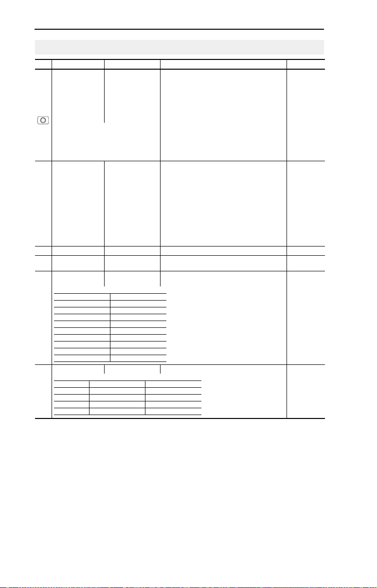
Mounting Considerations
• Mount the drive upright on a flat, vertical and level surface.
Frame Screw Size Screw Torque DIN Rail
B M4 (#8-32) 1.56-1.96 N-m (14-17 lb.-in.) 35 mm
C M5 (#10-24) 2.45-2.94 N-m (22-26 lb.-in.) –
B (IP66,
Type 4X)
• Protect the cooling fan by avoiding dust or metallic particles.
• Do not expose to a corrosive atmosphere.
• Protect from moisture and direct sunlight.
Minimum Mounting Clearances
See Page 21 for mounting dimensions.
M6 (#12-24) 3.95-4.75 N-m (35-42 lb.-in.) –
120 mm
(4.7 in.)
120 mm
(4.7 in.)
25 mm
(1.0 in.)
Closest object that
may restrict air flow
through the drive heat
sink and chassis
120 mm
(4.7 in.)
Mounting Option A
No clearance required
between drives.
120 mm
(4.7 in.)
Mounting Option B
Ambient Operating Temperatures
Ambient Temperature Enclosure Rating Minimum Mounting
Minimum Maximum
IP20, NEMA/UL Type Open Use Mounting Option A
-10°C (14°F)
40°C (104°F)
IP66, NEMA/UL Type 4X Use Mounting Option A
IP30, NEMA/UL Type 1
50°C (122°F) IP20, NEMA/UL Type Open Use Mounting Option B
(1)
Rating requires installation of the PowerFlex 40 IP 30, NEMA/UL Type 1 option kit.
Clearances
(1)
Use Mounting Option B
Page 5
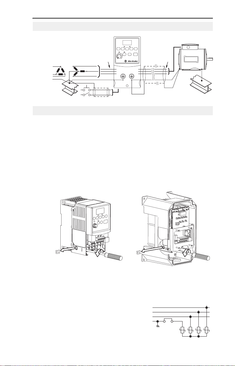
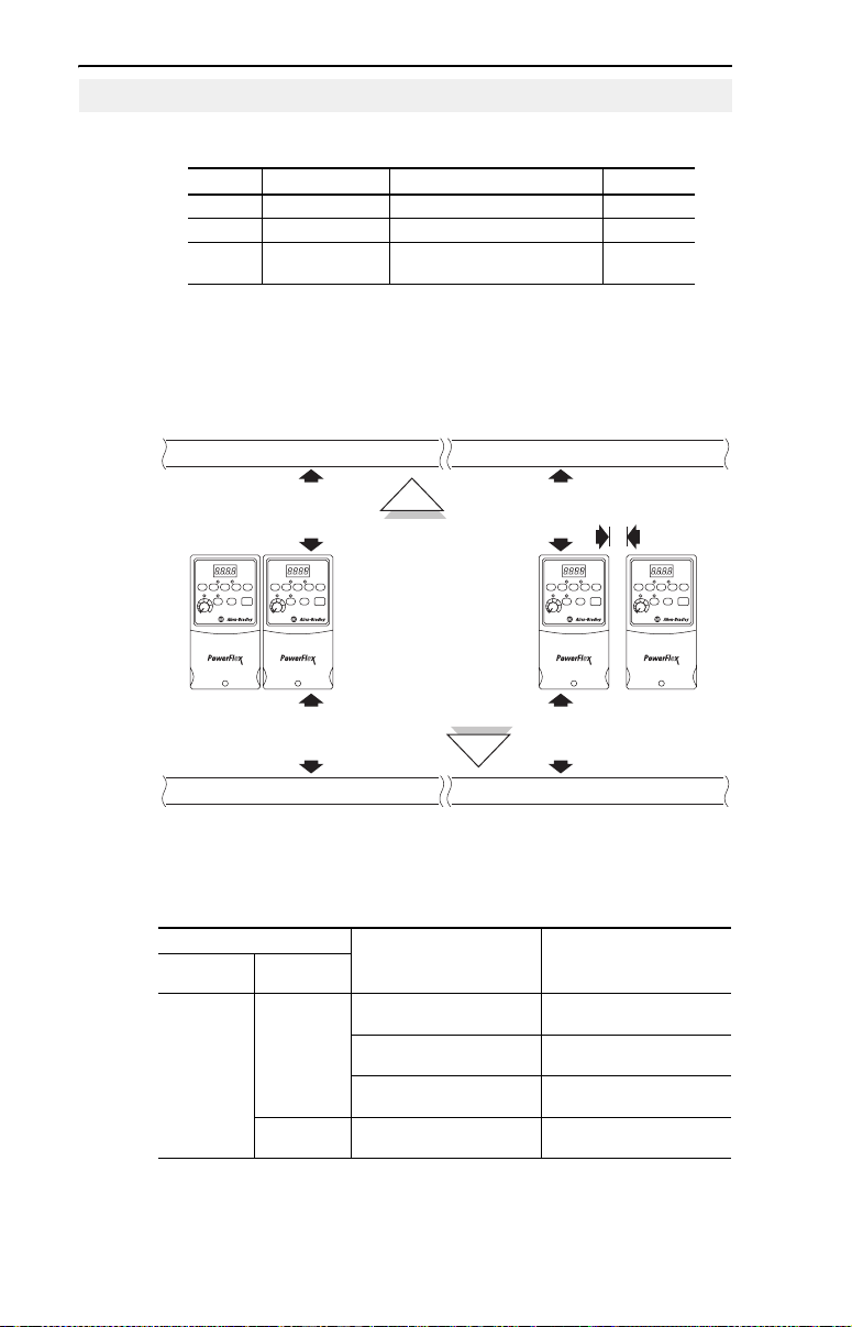
Typical Grounding
English-3
R/L1
S/L2
T/L3
SHLD
U/T1
V/T2
W/T3
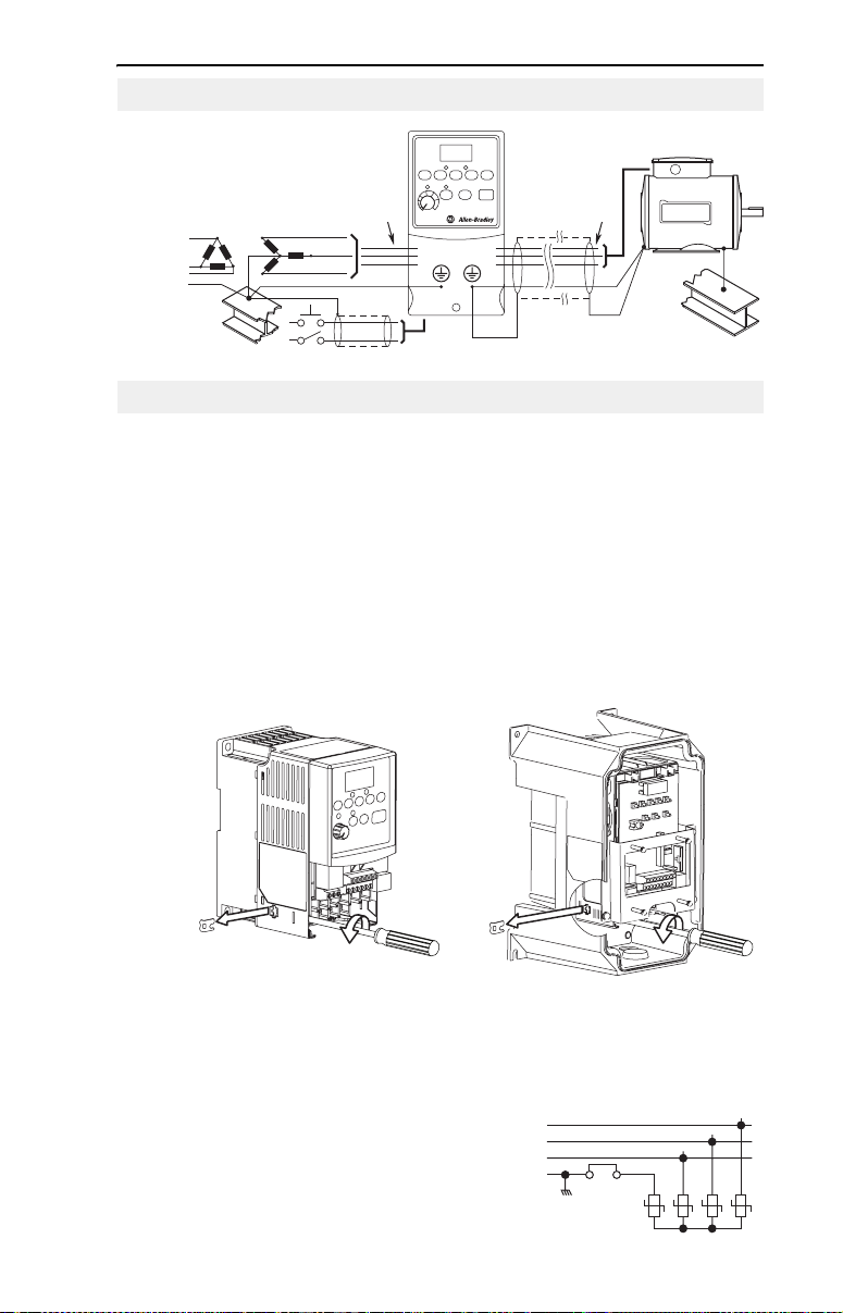
Disconnecting MOVs
To prevent drive damage, the MOVs connected to ground shall be
disconnected if the drive is installed on an ungrounded distribution
system where the line-to-ground voltages on any phase could exceed
125% of the nominal line-to-line voltage. To disconnect these devices,
remove the jumper shown in the figures below.
1. Turn the screw counterclockwise to loosen.
2. Pull the jumper completely out of the drive chassis.
3. Tighten the screw to keep it in place.
Jumper Location
IP66, NEMA/UL Type 4XIP20, NEMA/UL Type Open
Important: Tighten screw after jumper removal.
Phase to Ground MOV Removal
AC Input
R/L1
S/L2
T/L3
Three-Phase
Jumper
123
4
Page 6

English-4
CE Conformity
Refer to the PowerFlex 40 User Manual for details on how to comply
with the Low Voltage (LV) and Electromagnetic Compatibility (EMC)
Directives.
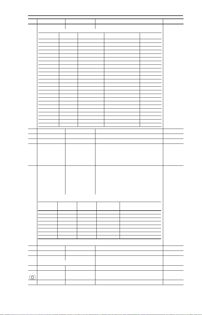
Specifications, Fuses and Circuit Breakers
Drive Ratings
Catalog
Number
100 - 120V AC (±10%) – 1-Phase Input, 0 - 230V 3-Phase Output
22B-V2P3x104 0.4 (0.5) 2.3 90-132 1.15 9.0 15 140M-C2E-C16 100-C12 40
22B-V5P0x104 0.75 (1.0) 5.0 90-132 2.45 20.3 35 140M-D8E-C20 100-C23 60
22B-V6P0x104 1.1 (1.5) 6.0 90-132 3.0 24.0 40 140M-F8E-C32 100-C37 80
200 - 240V AC (±10%) – 1-Phase
22B-A2P3x104 0.4 (0.5) 2.3 180-264 1.15 6.0 10 140M-C2E-B63 100-C09 40
22B-A5P0x104 0.75 (1.0) 5.0 180-264 2.45 12.0 20 140M-C2E-C16 100-C12 60
22B-A8P0x104 1.5 (2.0) 8.0 180-264 4.0 18.0 30 140M-D8E-C20 100-C23 85
22B-A012x104 2.2 (3.0) 12.0 180-264 5.5 25.0 40 140M-F8E-C32 100-C37 125
200 - 240V AC (±10%) – 3-Phase Input, 0 - 230V 3-Phase Output
22B-B2P3x104 0.4 (0.5) 2.3 180-264 1.15 2.5 6 140M-C2E-B40 100-C07 40
22B-B5P0x104 0.75 (1.0) 5.0 180-264 2.45 5.7 10 140M-C2E-C10 100-C09 60
22B-B8P0x104 1.5 (2.0) 8.0 180-264 4.0 9.5 15 140M-C2E-C16 100-C12 85
22B-B012x104 2.2 (3.0) 12.0 180-264 5.5 15.5 25 140M-C2E-C16 100-C23 125
22B-B017x104 3.7 (5.0) 17.5 180-264 8.6 21.0 30 140M-F8E-C25 100-C23 180
22B-B024x104 5.5 (7.5) 24.0 180-264 11.8 26.1 40 140M-F8E-C32 100-C37 235
22B-B033x104 7.5 (10.0) 33.0 180-264 16.3 34.6 60 140M-G8E-C45 100-C60 305
380 - 480V AC (±10%) – 3-Phase Input, 0 - 460V 3-Phase Output
22B-D1P4x104 0.4 (0.5) 1.4 342-528 1.4 1.8 3 140M-C2E-B25 100-C07 35
22B-D2P3x104 0.75 (1.0) 2.3 342-528 2.3 3.2 6 140M-C2E-B40 100-C07 50
22B-D4P0x104 1.5 (2.0) 4.0 342-528 4.0 5.7 10 140M-C2E-B63 100-C09 70
22B-D6P0x104 2.2 (3.0) 6.0 342-528 5.9 7.5 15 140M-C2E-C10 100-C09 100
22B-D010x104 4.0 (5.0) 10.5 342-528 10.3 13.0 20 140M-C2E-C16 100-C23 160
22B-D012x104 5.5 (7.5) 12.0 342-528 11.8 14.2 25 140M-D8E-C20 100-C23 175
22B-D017x104 7.5 (10.0) 17.0 342-528 16.8 18.4 30 140M-D8E-C20 100-C23 210
22B-D024x104 11.0 (15.0) 24.0 342-528 23.4 26.0 50 140M-F8E-C32 100-C43 300
460 - 600V AC (±10%) – 3-Phase Input, 0 - 575V 3-Phase Output
22B-E1P7x104 0.75 (1.0) 1.7 414-660 2.1 2.3 6 140M-C2E-B25 100-C09 50
22B-E3P0x104 1.5 (2.0) 3.0 414-660 3.65 3.8 6 140M-C2E-B40 100-C09 70
22B-E4P2x104 2.2 (3.0) 4.2 414-660 5.2 5.3 10 140M-C2E-B63 100-C09 100
22B-E6P6x104 4.0 (5.0) 6.6 414-660 8.1 8.3 15 140M-C2E-C10 100-C09 160
22B-E9P9x104 5.5 (7.5) 9.9 414-660 12.1 11.2 20 140M-C2E-C16 100-C16 175
22B-E012x104 7.5 (10.0) 12.2 414-660 14.9 13.7 25 140M-C2E-C16 100-C23 210
22B-E019x104 11.0 (15.0) 19.0 414-660 23.1 24.1 40 140M-D8E-C25 100-C30 300
(1)
In the Catalog Numbers listed “x” represents enclosure type. Specifications are valid for all
enclosure types. IP66, NEMA/UL Type 4X drive ratings are only available as Frame B drives.
(2)
200-240V AC - 1-Phase drives are also available with an integral EMC filter. Catalog suffix
changes from N104 to N114. Filter option is not available for IP66, NEMA/UL Type 4X rated drives.
Output Ratings Input Ratings Branch Circuit Protection
(1)
kW (HP) Amps
Voltage
Range kVA Amps Fuses
(2)
Input, 0 - 230V 3-Phase Output
140M Motor
Protectors Contactors
Power
Dissipation
IP20 Open
Watt s
Page 7
English-5
Input/Output Ratings
Output Frequency: 0-400 Hz (Programmable)
Efficiency: 97.5% (Typical)
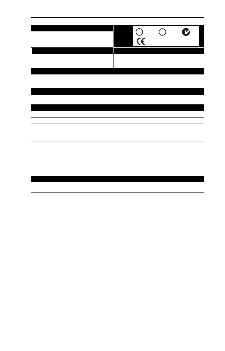
Approvals
D
9
E
6
T
6
S
X
I
L
U
UL508C
L
®
I
N
Q
D
E
C
T
O
N
D
9
E
6
T
6
S
X
I
L
U
CSA 22.2
L
C
®
I
N
Q
D
E
C
T
O
N
EMC Directive 89/336
LV: EN 50178, EN 60204
EMC: EN 61800-3, EN 50081-1, EN 50082-2
Digital Control Inputs (Input Current = 6mA) Analog Control Inputs
SRC (Source) Mode:
18-24V = ON
0-6V = OFF
SNK (Sink) Mode:
0-6V = ON
18-24V = OFF
4-20mA Analog: 250 ohm input impedance
0-10V DC Analog: 100k ohm input impedance
External Pot: 1-10k ohms, 2 Watt minimum
Control Output
Programmable Output (form C relay)
Resistive Rating: 3.0A at 30V DC, 3.0A at 125V AC, 3.0A at 240V AC
Inductive Rating: 0.5A at 30V DC, 0.5A at 125V AC, 0.5A at 240V AC
Opto Outputs
30V DC, 50mA
Non-inductive
Analog Outputs (10 bit)
0-10V, 1k ohm Min.
4-20mA, 525 ohm Max.
Fuses and Circuit Breakers
Recommended Fuse Type: UL Class J, CC, T or Type BS88; 600V (550V) or equivalent.
Recommended Circuit Breakers: HMCP circuit breakers or equivalent.
Protective Features
Motor Protection: I2t overload protection - 150% for 60 Secs, 200% for 3 Secs (Provides Class 10 protection)
Overcurrent: 200% hardware limit, 300% instantaneous fault
Over Voltage: 100-120V AC Input – Trip occurs at 405V DC bus voltage (equivalent to 150V AC incoming line)
Under Voltage: 100-120V AC Input – Trip occurs at 210V DC bus voltage (equivalent to 75V AC incoming line)
200-240V AC Input – Trip occurs at 405V DC bus voltage (equivalent to 290V AC incoming line)
380-460V AC Input – Trip occurs at 810V DC bus voltage (equivalent to 575V AC incoming line)
460-600V AC Input – Trip occurs at 1005V DC bus voltage (equivalent to 711V AC incoming line)
200-240V AC Input – Trip occurs at 210V DC bus voltage (equivalent to 150V AC incoming line)
380-480V AC Input – Trip occurs at 390V DC bus voltage (equivalent to 275V AC incoming line)
460-600V AC Input – If P042 = 3 “High Voltage” trip occurs at 487V DC bus voltage (344V AC incoming line);
If P042 = 2 “Low Voltage” trip occurs at 390V DC bus voltage (275V AC incoming line)
Control Ride Through: Minimum ride through is 0.5 Secs - typical value 2 Secs
Faultless Power Ride Through: 100 milliseconds
Dynamic Braking
Internal brake IGBT included with all ratings except No Brake versions. Refer to Appendix B of the PowerFlex 40 User Manual
for DB resistor ordering information.
Page 8
English-6
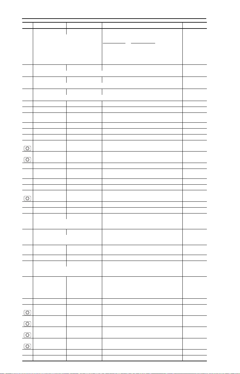
Power Wiring
Power Wire Rating Recommended Copper
Wire
Unshielded 600V, 75°C (167°F) THHN/THWN 15 Mils insulated, dry location
Shielded 600V, 75°C or 90°C (167°F or 194°F) RHH/
RHW-2
Shielded Tray rated 600V, 75°C or 90°C (167°F or 194°F)
RHH/RHW-2
Anixter OLF-7xxxxx,
Belden 29501-29507 or
equivalent
Anixter 7V-7xxxx-3G
Shawflex 2ACD/3ACD or
equivalent
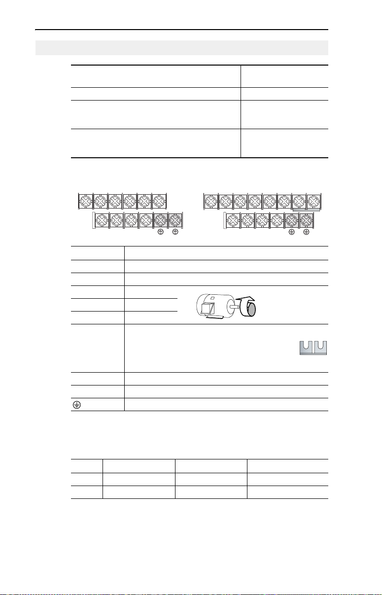
Power Terminal Block
B Frame C Frame
Terminal
(1)
DC+
V/T2T/L3S/L2R/L1 U/T1 W/T3
BR+ BR-DC-
Description
DC+
BR+ BR-DC-
V/T2T/L3S/L2R/L1 U/T1 W/T3 P2 P1
R/L1, S/L2 1-Phase Input
R/L1, S/L2, T/L3 3-Phase Input
U/T1 To Motor U/T1
V/T2 To Motor V/T2
W/T3 To Motor W/T3
=
Switch any two motor
leads to change
forward direction.
DC Bus Inductor Connection (C Frame drives only.)
P2, P1
The C Frame drive is shipped with a jumper between
Terminals P2 and P1. Remove this jumper only when a DC
Bus Inductor will be connected. Drive will not power up
without a jumper or inductor connected.
DC+, DC- DC Bus Connection
BR+, BR- Dynamic Brake Resistor Connection
Safety Ground - PE
(1)
Important: Terminal screws may become loose during shipment. Ensure that all
terminal screws are tightened to the recommended torque before applying power to
the drive.
Power Terminal Block Specifications
Frame Maximum Wire Size
2
B 5.3 mm
C 8.4 mm
(2)
Maximum/minimum sizes that the terminal block will accept - these are not
(10 AWG) 1.3 mm2 (16 AWG) 1.7-2.2 N-m (16-19 lb.-in.)
2
(8 AWG) 1.3 mm2 (16 AWG) 2.9-3.7 N-m (26-33 lb.-in.)
(2)
Minimum Wire Size
(2)
Torque
recommendations.
Page 9
Input Power Conditions
Input Power Condition Corrective Action
Low Line Impedance (less than 1% line reactance) • Install Line Reactor
Greater than 120 kVA supply transformer
• or Isolation Transformer
(2)
• or Bus Inductor – 5.5-11 kW
(7.5-15 HP) drives only
Line has power factor correction capacitors • Install Line Reactor
Line has frequent power interruptions
Line has intermittent noise spikes in excess of
6000V (lightning)
Phase to ground voltage exceeds 125% of normal
line to line voltage
Ungrounded distribution system
240V open delta configuration (stinger leg)
(1)
For drives applied on an open delta with a middle phase grounded neutral system, the
• or Isolation Transformer
• Remove MOV jumper to ground.
• or Install Isolation Transformer
with grounded secondary if
necessary.
(1)
• Install Line Reactor
phase opposite the phase that is tapped in the middle to the neutral or earth is
referred to as the “stinger leg,” “high leg,” “red leg,” etc. This leg should be identified
throughout the system with red or orange tape on the wire at each connection point.
The stinger leg should be connected to the center Phase B on the reactor. Refer to the
PowerFlex 40 User Manual for specific line reactor part numbers.
(2)
Refer to Appendix B of the PowerFlex 40 User Manual for accessory ordering
information.
English-7
I/O Wiring Recommendations
Wire Type(s)
(4)
Description Minimum Insulation
(3)
Rating
2
Belden 8760/9460
(or equiv.)
Belden 8770
(or equiv.)
(3)
If the wires are short and contained within a cabinet which has no sensitive circuits,
the use of shielded wire may not be necessary, but is always recommended.
(4)
Stranded or solid wire.
(18AWG), twisted pair, 100% shield
0.8 mm
with drain.
2
(18AWG), 3 conductor, shielded for
0.8 mm
remote pot only.
300V
60 degrees C
(140 degrees F)
I/O Terminal Block Specifications
(5)
Frame Maximum Wire Size
B & C 1.3 mm
(5)
Maximum / minimum that the terminal block will accept - these are not
2
(16 AWG) 0.2 mm2 (24 AWG) 0.5-0.8 N-m (4.4-7 lb.-in.)
Minimum Wire Size
recommendations.
Refer to the PowerFlex 40 User Manual for recommendations on
maximum power and control cable length.
(5)
Torque
Page 10
English-8
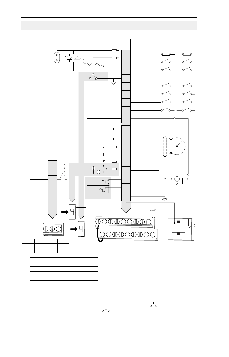
Control Terminal Block
Control Wiring Block Diagram
(4)
Enable
Jumper
Relay N.O.
Relay Common
Relay N.C.
Resistive 3.0A 3.0A 3.0A
Inductive 0.5A 0.5A 0.5A
P036 [Start Source] Stop I/O Terminal 01 Stop
R1
R2
R3
0-10V
0-20mA
R1 R2 R3
30V DC 125V AC 240V AC
Keypad Per P037 Coast
3-Wire Per P037 Per P037
2-Wire Per P037 Coast
RS485 Port Per P037 Coast
SNK
SRC
SRCSNK
+24V
+10V
0-10V
0/4-20mA
30V DC
50mA
Non-inductive
Analog Output Select
01 02 03 04 05
11 12 13 14 15
(1)
(1)
Important: I/O Terminal 01 is always a coast to
stop input except when P036 [Start Source] is set to
“3-Wire” or “Momt FWD/REV” control. In three wire
control, I/O Terminal 01 is controlled by P037 [Stop
Mode]. All other stop sources are controlled by P037
(1)(4)
Stop
01
Start/Run FWD
02
Direction/Run REV
03
Digital Common
04
Digital Input 1
05
Digital Input 2
06
Digital Input 3
07
Digital Input 4
08
Opto Common
09
+24V DC
11
+10V DC
12
0-10V (or ±10V) Input
13
Analog Common
14
4-20mA Input
15
Analog Output
16
Opto Output 1
17
Opto Output 2
18
RS485 Shield
19
ENBL
06 07 08 09
16 17 18 19
[Stop Mode].
Important: The drive is shipped with a jumper installed between I/O Terminals 01 and 11. Remove
this jumper when using I/O Terminal 01 as a stop or enable input.
(2)
Two wire control shown. For three wire control use a momentary input on I/O Terminal 02 to
command a start. Use a maintained input for I/O Terminal 03 to change direction.
(3)
When using an opto output with an inductive load such as a relay, install a recovery diode parallel
to the relay as shown, to prevent damage to the output.
(4)
When the ENBL jumper is removed, I/O Terminal 01 will always act as a hardware enable, causing
a coast to stop without software interpretation. Refer to the PowerFlex 40 User Manual for more
information.
Typical
SRC Wiring
(2)
Enable
Jumper
Pot must be
1-10k ohm
2 Watt Min.
Common
(4)
RS485
(DSI)
Typical
SNK Wiring
(3)
24V
1
Page 11

English-9
Control I/O Terminal Designations
No. Signal Default Description Param.
R1 Relay N.O. Fault Normally open contact for output relay. A055
R2 Relay Common – Common for output relay.
R3 Relay N.C. Fault Normally closed contact for output relay. A055
Analog Output Select
DIP Switch
Sink/Source
DIP Switch
(1)
01 Stop
02 Star t/Run FWD Not Active Command comes from the integral keypad by default.
03 Direction/Run REV Not Active P036, P037,
04 Digital Common – For digital inputs. Electronically isolated with digital
05 Digital Input 1 Preset Freq Program with A051 [Digital In1 Sel]. A051
06 Digital Input 2 Preset Freq Program with A052 [Digital In2 Sel]. A052
07 Digital Input 3 Local Program with A053 [Digital In3 Sel]. A053
08 Digital Input 4 Jog Forward Program with A054 [Digital In4 Sel]. A054
09 Opto Common – For opto-coupled outputs. Electronically isolated with
11 +24V DC – Referenced to Digital Common.
12 +10V DC – Referenced to Analog Common.
13 ±10V In
14 Analog Common – For 0-10V In or 4-20mA In. Electronically isolated
15 4-20mA In
16 Analog Output OutFreq 0-10 The default analog output is 0-10V. To covert to a
17 Opto Output 1 MotorRunning Program with A058 [Opto Out1 Sel] A058, A059,
18 Opto Output 2 At Frequency Program with A061 [Opto Out2 Sel] A061, A062,
19 RS485 (DSI) Shield – Terminal should be connected to safety ground - PE
(1)
(2)
(2)
See Footnotes (1) and (4) on page 8.
0-10V In and 4-20mA In are distinct input channels and may be connected simultaneously.
0-10V Sets analog output to either voltage or current. Setting must match
Source (SRC) Inputs can be wired as Sink (SNK) or Source (SRC) via DIP Switch
Coast The factory installed jumper or a normally closed
Not Active For external 0-10V (unipolar) or ±10V (bipolar) input
(2)
Not Active For external 4-20mA input supply
A065 [Analog Out Sel].
setting.
input must be present for the drive to start.
To disable reverse operation, see A095 [Reverse
Disable].
inputs from analog I/O and opto outputs.
opto outputs from analog I/O and digital inputs.
Drive supplied power for digital inputs.
Maximum output current is 100mA.
Drive supplied power for 0-10V external
potentiometer.
Maximum output current is 15mA.
supply (input impedance = 100k ohm) or
potentiometer wiper.
with analog inputs and outputs from digital I/O and
opto outputs.
(input impedance = 250 ohm).
current value, change the Analog Output Select DIP
Switch to 0-20mA. Program with A065 [Analog Out
Sel]. Max analog value can be scaled with A066
[Analog Out High].
Maximum Load: 4-20mA = 525 ohm (10.5V)
when using the RS485 (DSI) communications port.
0-10V = 1k ohm (10mA)
(1)
P036
P036, P037
A095
P038
P038,
A051-A054,
A123, A132
P038,
A051-A054,
A132
A065, A066
A064
A064
Inputs may be used independently for speed control or jointly when operating in PID mode.
Page 12

English-10
Prepare For Drive Start-Up
ATTENTION: Power must be applied to the drive to perform the
following start-up procedures. Some of the voltages present are at
!
incoming line potential. To avoid electric shock hazard or damage to
equipment, only qualified service personnel should perform the
following procedure. Thoroughly read and understand the procedure
before beginning. If an event does not occur while performing this
procedure, Do Not Proceed. Remove All Power including user
supplied control voltages. User supplied voltages may exist even when
main AC power is not applied to the drive. Correct the malfunction
before continuing.
Before Applying Power to the Drive
❏ 1. Confirm that all inputs are connected to the correct terminals and are
secure.
❏ 2. Verify that AC line power at the disconnect device is within the rated
value of the drive.
❏ 3. Verify that any digital control power is 24 volts.
❏ 4. Verify that the Sink (SNK)/Source (SRC) Setup DIP Switch is set to
match your control wiring scheme. See page 8 for location.
Important: The default control scheme is Source (SRC). The Stop
terminal is jumpered (I/O Terminals 01 and 11) to allow
starting from the keypad. If the control scheme is changed
to Sink (SNK), the jumper must be removed from I/O
Terminals 01 and 11 and installed between I/O Terminals
01 and 04.
❏ 5. Verify that the Stop input is present or the drive will not start.
Important: If I/O Terminal 01 is used as a stop input, the jumper
between I/O Terminals 01 and 11 must be removed.
Applying Power to the Drive
❏ 6. Apply AC power and control voltages to the drive.
❏ 7. Familiarize yourself with the integral keypad features (see next page)
before setting any Program Group parameters.
If a fault appears on power up, refer to page 20 for an explanation of the
fault code. For complete troubleshooting information, refer to the
PowerFlex 40 User Manual.
Page 13
English-11
Start, Stop, Direction and Speed Control
Factory default parameter values allow the drive to be controlled from
the integral keypad. No programming is required to start, stop, change
direction and control speed directly from the integral keypad.
Important: To disable reverse operation, see A095 [Reverse Disable].
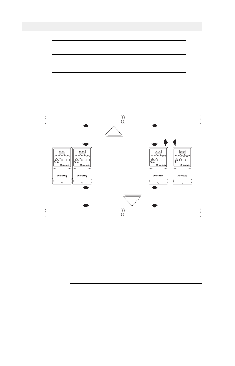
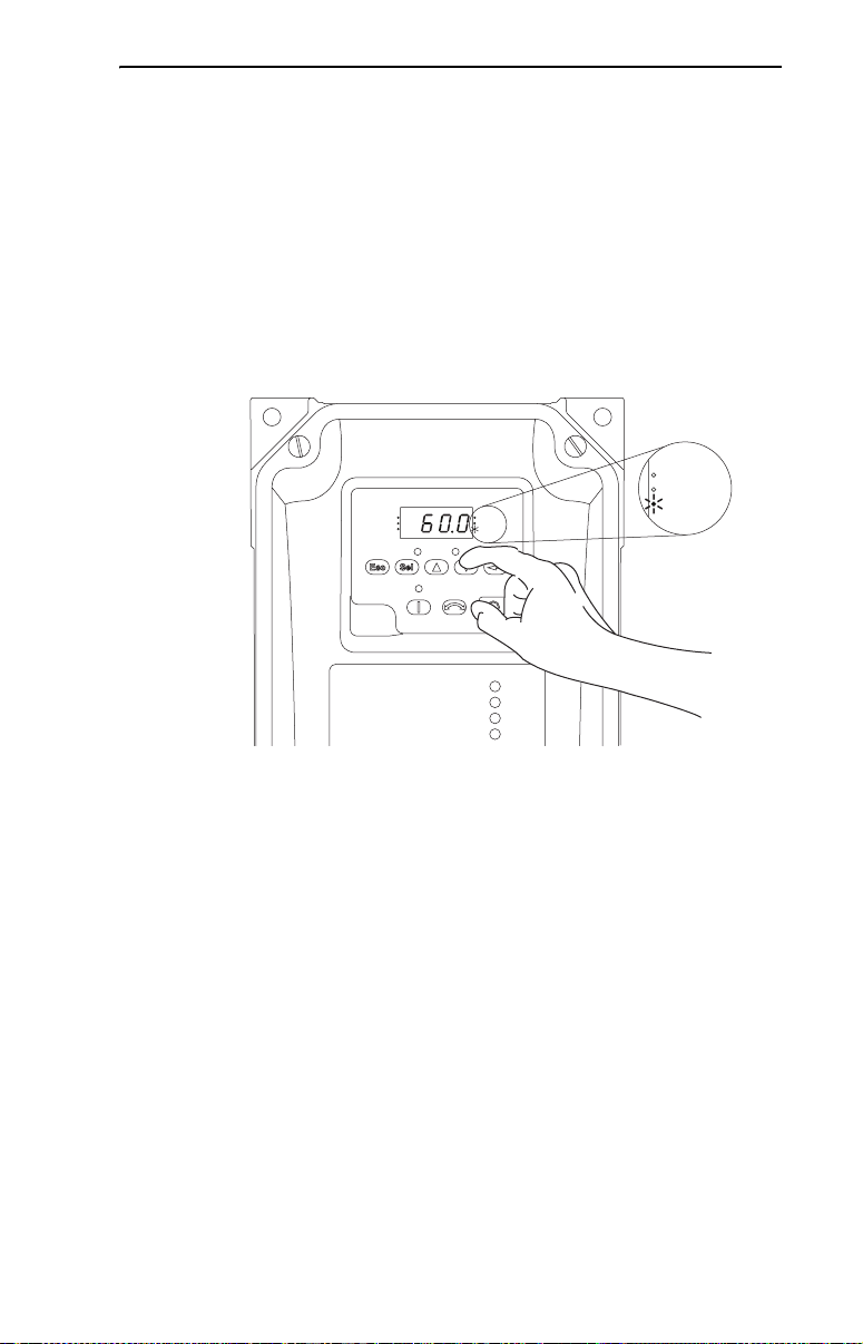
Changing the Speed Reference of an IP66, NEMA/UL Type 4X rated
drive
When a Display Group parameter, for example, d001 [Output Freq] is
displayed, and P038 [Speed Ref] is set to A069 [Internal Freq], you can
change the internal frequency using the Up Arrow and Down Arrow
keys.
VOLTS
AMPS
RUN
FWD
REV
PROGRAM
VOLTS
AMPS
HERTZ
FAULT
HERTZ
When the internal frequency is being adjusted, its value is displayed and
the Hertz LED flashes. Any changes are saved immediately. The display
then returns to the Display Group parameter previously shown.
TIP: By default, the speed reference of an IP66, NEMA/UL Type 4X
rated drive is set to the internal frequency, A069 [Internal Freq].
TIP: You can also change the speed reference by editing the parameter
A069 [Internal Freq] in program mode. For details on how to enter the
program mode, see the section, “Viewing and Editing Parameters.”
The default value of A069 [Internal Freq] is 0 Hz. For IP20 rated
PowerFlex 40 drives, the default value of this parameter is 60 Hz.
Page 14
English-12
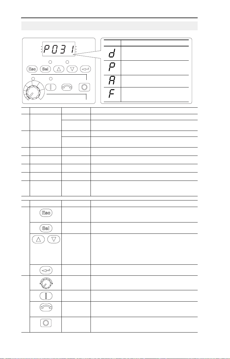
Integral Keypad
➏
➍
➋
PROGRAM
➎
➊
RUN
FWD
REV
FAULT
➌
VOLTS
AMPS
HERTZ
➐
➑
➒
Menu Description
Display Group (View Only)
Consists of commonly viewed drive operating
conditions.
Basic Program Group
Consists of most commonly used
programmable functions.
Advanced Program Group
Consists of remaining programmable functions.
Fault Designator
Consists of list of codes for specific fault
conditions. Displayed only when fault is present.
No. LED LED State Description
Run/Direction
➊
Status
Steady Red Indicates drive is running and commanded motor direction.
Flashing Red Drive has been commanded to change direction. Indicates
actual motor direction while decelerating to zero.
Alphanumeric
➋
Display
Displayed Units Steady Red Indicates the units of the parameter value being displayed.
➌
Program Status Steady Red Indicates parameter value can be changed.
➍
Fault Status Flashing Red Indicates drive is faulted.
➎
Pot Status Steady Green Indicates potentiometer on Integral Keypad is active.
➏
Start Key Status Steady Green Indicates Start key on Integral Keypad is active.
➐
Steady Red Indicates parameter number, parameter value, or fault code.
Flashing Red Single digit flashing indicates that digit can be edited.
All digits flashing indicates a fault condition.
The Reverse key is also active unless disabled by A095
[Reverse Disable].
No. Key Name Description
➑
Escape Back one step in programming menu.
Select Advance one step in programming menu.
Up Arrow
Down Arrow
Cancel a change to a parameter value and exit Program
Mode.
Select a digit when viewing parameter value.
Scroll through groups and parameters.
Increase/decrease the value of a flashing digit.
Used to adjust internal frequency of IP66, NEMA/UL Type 4X
rated drives only when a Display Group parameter is shown
and P038 [Speed Reference] is set to internal frequency,
A069 [Internal Freq].
➒
Enter Advance one step in programming menu.
Potentiometer
Save a change to a parameter value.
(1)
Used to control speed of drive. Default is active.
Controlled by parameter P038 [Speed Reference].
Start Used to start the drive. Default is active.
Controlled by parameter P036 [Start Source].
Reverse Used to reverse direction of the drive. Default is active.
Stop Used to stop the drive or clear a fault.
Controlled by parameters P036 [Start Source] and A095
[Reverse Disable].
This key is always active.
Controlled by parameter P037 [Stop Mode].
(1)
IP66, NEMA/UL Type 4X rated drives are not equipped with a potentiometer.
(1)
Page 15
See the PowerFlex 40 User Manual for more information on parameters.
English-13
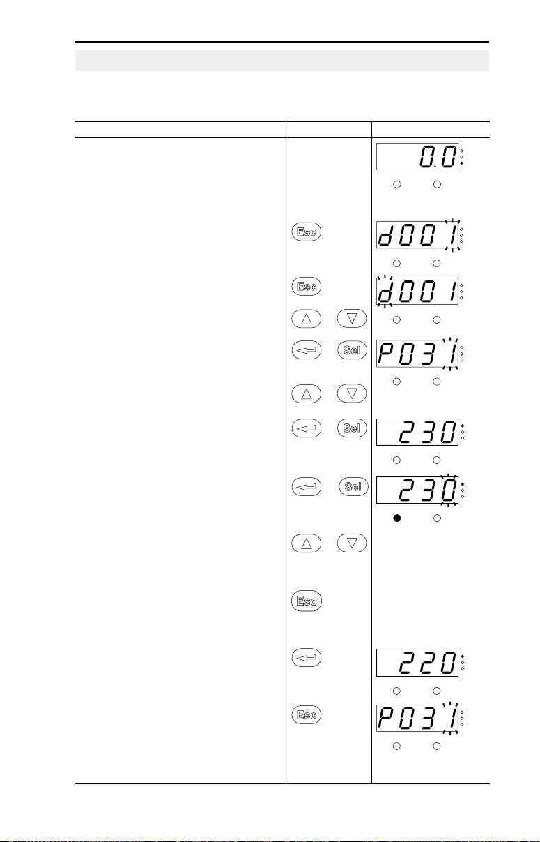
Viewing and Editing Parameters
The last user-selected Display Group parameter is saved when power is removed and is displayed by
default when power is reapplied.
The following is an example of basic integral keypad and display functions. This example provides basic
navigation instructions and illustrates how to program the first Program Group parameter.
Step Key(s) Example Displays
1. When power is applied, the last user-selected
Display Group parameter number is briefly
displayed with flashing characters. The display
then defaults to that parameter’s current value.
(Example shows the value of d001 [Output
Freq] with the drive stopped.)
2. Press Esc once to display the Display Group
parameter number shown on power-up. The
parameter number will flash.
VOLTS
AMPS
HERTZ
FAULTPROGRAM
VOLTS
AMPS
HERTZ
FAULTPROGRAM
3. Press Esc again to enter the group menu. The
group menu letter will flash.
4. Press the Up Arrow or Down Arrow to scroll
through the group menu (d, P and A).
5. Press Enter or Sel to enter a group. The right
digit of the last viewed parameter in that group
will flash.
6. Press the Up Arrow or Down Arrow to scroll
through the parameters that are in the group.
7. Press Enter or Sel to view the value of a
parameter. If you do not want to edit the value,
press Esc to return to the parameter number.
8. Press Enter or Sel to enter program mode to
edit the parameter value. The right digit will
flash and the Program LED will illuminate if the
parameter can be edited.
9. Press the Up Arrow or Down Arrow to change
the parameter value. If desired, press Sel to
move from digit to digit or bit to bit. The digit or
bit that you can change will flash.
10.Press Esc to cancel a change. The digit will
stop flashing, the previous value is restored and
the Program LED will turn off.
Or
Press Enter to save a change. The digit will stop
flashing and the Program LED will turn off.
VOLTS
AMPS
HERTZ
or
or
FAULTPROGRAM
VOLTS
AMPS
HERTZ
FAULTPROGRAM
or
or
or
VOLTS
AMPS
HERTZ
FAULTPROGRAM
VOLTS
AMPS
HERTZ
FAULTPROGRAM
or
VOLTS
AMPS
HERTZ
FAULTPROGRAM
11.Press Esc to return to the parameter list.
Continue to press Esc to back out of the
programming menu.
If pressing Esc does not change the display,
then d001 [Output Frequency] is displayed.
Press Enter or Sel to enter the group menu.
The Basic Program Group contains the most commonly changed parameters.
VOLTS
AMPS
HERTZ
FAULTPROGRAM
Page 16
English-14
See the PowerFlex 40 User Manual for more information on parameters.
Display Group Parameters
No. Parameter Min/Max Display/Options
d001 [Output Freq] 0.0/ [Maximum Freq] 0.1 Hz
d002 [Commanded Freq] 0.0/ [Maximum Freq] 0.1 Hz
d003 [Output Current] 0.00/(Drive Amps × 2) 0.01 Amps
d004 [Output Voltage] 0/Drive Rated Volts 1 VAC
d005 [DC Bus Voltage] Based on Drive Rating 1 VDC
d006 [Drive Status] 0/1 (1 = Condition True) Bit 3
d007-
[Fault x Code] F2/F122 F1
d009
d010 [Process Display] 0.00/9999 0.01 – 1
d012 [Control Source] 0/9 Digit 1 = Speed Command
d013 [Contrl In Status] 0/1 (1 = Input Present) Bit 3
d014 [Dig In Status] 0/1 (1 = Input Present) Bit 3
d015 [Comm Status] 0/1 (1 = Condition True) Bit 3
d016 [Control SW Ver] 1.00/99.99 0.01
d017 [Drive Type] 1001/9999 1
d018 [Elapsed Run Time] 0/9999 Hrs 1 = 10 Hrs
d019 [Testpoint Data] 0/FFFF 1 Hex
d020 [Analog In 0-10V] 0.0/100.0% 0.1%
d021 [Analog In 4-20mA] 0.0/100.0% 0.1%
d022 [Output Power] 0.00/(Drive Power × 2) 0.01 kW
d023 [Output Powr Fctr] 0.0/180.0 deg 0.1 deg
d024 [Drive Temp] 0/120 degC 1 degC
d025 [Counter Status] 0/9999 1
d026 [Timer Status] 0.0/9999 Secs 0.1 Secs
d028 [Stp Logic Status] 0/7 1
d029 [Torque Current] 0.00/(Drive Amps × 2) 0.01 Amps
Decelerating Accelerating Forward Running
(See P038; 9 = “Jog Freq”) (See P036; 9 = “Jog”)
DB Trans On Stop Input Dir/REV In Start/FWD In
Digital In 4 Digital In 3 Digital In 2 Digital In 1
Comm Error DSI Option Transmitting Receiving
Bit 2 Bit 1 Bit 0
Digit 0 = Start Command
Bit 2 Bit 1 Bit 0
Bit 2 Bit 1 Bit 0
Bit 2 Bit 1 Bit 0
Smart Start-Up with Basic Program Group Parameters
The PowerFlex 40 is designed so that start up is simple and efficient. The Program Group
contains the most commonly used parameters.
= Stop drive before changing this parameter.
No. Parameter Min/Max Display/Options Default
P031 [Motor NP Volts] 20/Drive Rated Volts 1 VAC Based on Drive Rating
Set to the motor nameplate rated volts.
P032 [Motor NP Hertz] 15/400 Hz 1 Hz 60 Hz
Set to the motor nameplate rated frequency.
P033 [Motor OL Current] 0.0/(Drive Rated Amps× 2) 0.1 Amps Based on Drive Rating
Set to the maximum allowable motor current.
P034 [Minimum Freq] 0.0/400.0 Hz 0.1 Hz 0.0 Hz
Sets the lowest frequency the drive will output
continuously.
P035 [Maximum Freq] 0/400 Hz 1 Hz 60 Hz
Sets the highest frequency the drive will output.
P036 [Start Source] 0/6 0 = “Keypad”
Sets the control scheme used to star t the drive.
(1)
When active, the Reverse key is also active
unless disabled by A095 [Reverse Disable].
1 = “3-Wire”
2 = “2-Wire”
3 = “2-W Lvl Sens”
4 = “2-W Hi Speed”
5 = “Comm Port”
6 = “Momt FWD/REV”
(1)
0
Page 17
See the PowerFlex 40 User Manual for more information on parameters.
= Stop drive before changing this parameter.
No. Parameter Min/Max Display/Options Default
P037 [Stop Mode] 0/9 0 = “Ramp, CF”
Active stop mode for all stop sources [e.g. keypad,
run forward (I/O Terminal 02), run reverse (I/O
Terminal 03), RS485 port] except as noted below.
Important: I/O Terminal 01 is always a coast to
stop input except when P036 [Start Source] is set
for “3-Wire” control. When i n three wire control, I/O
Terminal 01 is controlled by P037 [Stop Mode].
P038 [Speed Reference] 0/7 0 = “Drive Pot”
Sets the source of the speed reference to the
drive.
Important: When A051 or A052 [Digital Inx Sel] is
set to option 2, 4, 5, 6, 13 or 14 and the digital
input is active, A051, A052, A053 or A054 will
override the speed reference commanded by this
parameter. Refer to Chapter 1 of the PowerFlex 40
User Manual for details.
1 = “Coast, CF”
2 = “DC Brake, CF”
3 = “DCBrkAuto,CF”
4 = “Ramp”
5 = “Coast”
6 = “DC Brake”
7 = “DC BrakeAuto”
8 = “Ramp+EM B,CF”
9 = “Ramp+EM Brk”
(1)
1 = “InternalFreq”
2 = “0-10V Input”
3 = “4-20mA Input”
4 = “Preset Freq”
5 = “Comm Port”
6 = “Stp Logic”
7 = “Anlg In Mult”
(1)
(1)
(1)
(1)
Stop input also clears active fault.
0
0
1 (IP66, Type 4X)
P039 [Accel Time 1] 0.0/600.0 Secs 0.1 Secs 10.0 Secs
Sets the rate of accel for all speed increases.
P040 [Decel Time 1] 0.1/600.0 Secs 0.1 Secs 10.0 Secs
Sets the rate of decel for all speed decreases.
P041 [Reset To Defalts] 0/1 0 = “Ready/Idle”
Resets all parameter values to factory defaults.
P042 [Voltage Class] 2/3
Sets the voltage class of 600V drives.
P043 [Motor OL Ret] 0/1 0 = “Disabled”
1 = “Factory Rset”
2 = “Low Voltage” (480V)
3 = “High Voltage” (600V)
1 = “Enabled”
0
3
0
Enables/disables the Motor Overload Retention function.
English-15
Page 18
English-16
See the PowerFlex 40 User Manual for more information on parameters.
Advanced Group Parameters
No. Parameter Min/Max Display/Options Default
[Digital In1 Sel]
A051
I/O Terminal 05
[Digital In2 Sel]
A052
I/O Terminal 06
[Digital In3 Sel]
A053
I/O Terminal 07
[Digital In4 Sel]
A054
I/O Terminal 08
(1)
Important: Speed source for IP66, NEMA/
UL Type 4X rated drives comes from A069
[Internal Freq].
A055 [Relay Out Sel] 0/24 0 = “Ready/Fault”
A056 [Relay Out Level] 0.0/9999 0.1 0.0
A058
[Opto Out1 Sel]
A061
[Opto Out2 Sel]
A059
[Opto Out1 Level]
A062
[Opto Out2 Level]
A055, A058 & A061 Setting A056, A059 & A062 Min/Max
6 0/400 Hz
7 0/180%
8 0/815 Volts
10 0/100%
16 0.1/9999 Secs
17 1/9999 Counts
18 1/180 degs
20 0/1
23 0/400 Hz
A064 [Opto Out Logic] 0/3 1 0
A064 Option Opto Out1 Logic Opto Out2 Logic
0 NO (Normally Open) NO (Normally Open)
1 NC (Normally Closed) NO (Normally Open)
2 NO (Normally Open) NC (Normally Closed)
3 NC (Normally Closed) NC (Normally Closed)
0/27 0 = “Not Used”
1 = “Acc & Dec 2”
2 = “Jog”
3 = “Aux Fault”
4 = “Preset Freq”
(1)
5 = “Local”
6 = “Comm Port”
7 = “Clear Fault”
8 = “RampStop,CF”
9 = “CoastStop,CF”
10 = “DCInjStop,CF”
11 = “Jog Forward”
12 = “Jog Reverse”
13 = “10V In Ctrl”
1 = “At Frequency”
2 = “MotorRunning”
3 = “Reverse”
4 = “Motor Overld”
5 = “Ramp Reg”
6 = “Above Freq”
7 = “Above Cur”
8 = “Above DCVolt”
9 = “Retries Exst”
10 = “Above Anlg V”
11 = “Logic In 1”
12 = “Logic In 2”
14 = “20mA In Ctrl”
15 = “PID Disable”
16 = “MOP Up”
17 = “MOP Down”
18 = “Timer Start”
19 = “Counter In”
20 = “Reset Timer”
21 = “Reset Countr”
22 = “Rset Tim&Cnt”
23 = “Logic In1”
24 = “Logic In2”
25 = “Current Lmt2”
26 = “Anlg Invert”
27 = “EM Brk Rlse”
13 = “Logic 1 & 2”
14 = “Logic 1 or 2”
15 = “StpLogic Out”
16 = “Timer Out”
17 = “Counter Out”
18 = “Above PF Ang”
19 = “Anlg In Loss”
20 = “ParamControl”
21 = “NonRec Fault”
22 = “EM Brk Cntrl”
23 = “Above Fcmd”
24 = “MsgControl” (for
FRN 6.01 and later)
0/24 See A055 for Options. 2
4
4
5
11
0
1
0.0/9999 0.1 0.0
Page 19
See the PowerFlex 40 User Manual for more information on parameters.
English-17
No. Parameter Min/Max Display/Options Default
A065 [Analog Out Sel] 0/23 1 0
Option Output Range Minimum Output Value
0 “OutFreq 0-10” 0-10V 0V = 0 Hz P035 [Maximum Freq] 0-10V
1 “OutCurr 0-10” 0-10V 0V = 0 Amps 200% Drive Rated FLA 0-10V
2 “OutVolt 0-10” 0-10V 0V = 0 Volts 120% Drive Rated Output Volts 0-10V
3 “OutPowr 0-10” 0-10V 0V = 0 kW 200% Drive Rated Power 0-10V
4 “TstData 0-10” 0-10V 0V = 0000 65535 (Hex FFFF) 0-10V
5 “OutFreq 0-20” 0-20 mA 0 mA = 0 Hz P035 [Maximum Freq] 0-20 mA
6 “OutCurr 0-20” 0-20 mA 0 mA = 0 Amps 200% Drive Rated FLA 0-20 mA
7 “OutVolt 0-20” 0-20 mA 0 mA = 0 Volts 120% Drive Rated Output Volts 0-20 mA
8 “OutPowr 0-20” 0-20 mA 0 mA = 0 kW 200% Drive Rated Power 0-20 mA
9 “TstData 0-20” 0-20 mA 0 mA = 0000 65535 (Hex FFFF) 0-20 mA
10 “OutFreq 4-20” 4-20 mA 4 mA = 0 Hz P035 [Maximum Freq] 0-20 mA
11 “OutCurr 4-20” 4-20 mA 4 mA = 0 Amps 200% Drive Rated FLA 0-20 mA
12 “OutVolt 4-20” 4-20 mA 4 mA = 0 Volts 120% Drive Rated Output Volts 0-20 mA
13 “OutPowr 4-20” 4-20 mA 4 mA = 0 kW 200% Drive Rated Power 0-20 mA
14 “TstData 4-20” 4-20 mA 4 mA = 0000 65535 (Hex FFFF) 0-20 mA
15 “OutTorq 0-10” 0-10V 0V = 0 Amps 200% Drive Rated FLA 0-10V
16 “OutTorq 0-20” 0-20 mA 0 mA = 0 Amps 200% Drive Rated FLA 0-20 mA
17 “OutTorq 4-20” 4-20 mA 4 mA = 0 Amps 200% Drive Rated FLA 0-20 mA
18 “Setpnt 0-10” 0-10V 0V = 0% 100.0% Setpoint Setting 0-10V
19 “Setpnt 0-20” 0-20 mA 0 mA = 0% 100.0% Setpoint Setting 0-20 mA
20 “Setpnt 4-20” 4-20 mA 4 mA = 0% 100.0% Setpoint Setting 0-20 mA
21 “MinFreq 0-10” 0-10V 0V = Min. Freq P035 [Maximum Freq] 0-10V
22 “MinFreq 0-20” 0-20 mA 0 mA = Min. Freq P035 [Maximum Freq] 0-20 mA
23 “MinFreq 4-20” 4-20 mA 4 mA = Min. Freq P035 [Maximum Freq] 0-20 mA
Maximum Output Value
[Analog Out High] DIP Switch Position
A066 [Analog Out High] 0/800% 1% 100%
A067 [Accel Time 2] 0.0/600.0 Secs 0.1 Secs 20.0 Secs
A068 [Decel Time 2] 0.1/600.0 Secs 0.1 Secs 20.0 Secs
A069 [Internal Freq] 0.0/400.0 Hz 0.1 Hz 0.0 Hz (for IP66,
A070
A071
A072
A073
A074
A075
A076
A077
[Preset Freq 0]
[Preset Freq 1]
[Preset Freq 2]
[Preset Freq 3]
[Preset Freq 4]
[Preset Freq 5]
[Preset Freq 6]
[Preset Freq 7]
(1)
(I/O Terminal 05)
(2)
(1)
0.0/400.0 Hz 0.1 Hz 0.0 Hz
To activate [Preset Freq 0] set P038 [Speed Reference] to option 4.
Input State
of Digital In 1
When a Digital Input is set to “Accel 2 & Decel 2”, and the input is active, that input overrides the settings in this table.
Input State
of Digital In 2
(I/O Terminal 06)
0 0 0 [Preset Freq 0] [Accel Time 1] / [Decel Time 1]
1 0 0 [Preset Freq 1] [Accel Time 1] / [Decel Time 1]
0 1 0 [Preset Freq 2] [Accel Time 2] / [Decel Time 2]
1 1 0 [Preset Freq 3] [Accel Time 2] / [Decel Time 2]
0 0 1 [Preset Freq 4] [Accel Time 1] / [Decel Time 1]
1 0 1 [Preset Freq 5] [Accel Time 1] / [Decel Time 1]
0 1 1 [Preset Freq 6] [Accel Time 2] / [Decel Time 2]
1 1 1 [Preset Freq 7] [Accel Time 2] / [Decel Time 2]
Input State
of Digital In 3
(I/O Terminal 07)
Frequency Source Accel / Decel Parameter Used
(2)
NEMA/UL Type
4X drives)
60.0 Hz (for
IP20 drives)
5.0 Hz
10.0 Hz
20.0 Hz
30.0 Hz
40.0 Hz
50.0 Hz
60.0 Hz
A078 [Jog Frequency] 0.0/[Maximum Freq] 0.1 Hz 10.0 Hz
A079 [Jog Accel/Decel] 0.1/600.0 Secs 0.1 Secs 10.0 Secs
A080 [DC Brake Time] 0.0/99.9 Secs 0.1 Secs 0.0 Secs
A setting of 99.9 Secs = Continuous
A081 [DC Brake Level] 0.0/(Drive Amps × 1.8) 0.1 Amps Amps × 0.05
A082 [DB Resistor Sel] 0/99 0 = “Disabled”
1 = “Normal RA Res”
2 = “NoProtection”
3-99 = % of Duty Cycle
0
A083 [S Curve %] 0/100% 1% 0% (Disabled)
Page 20
English-18
See the PowerFlex 40 User Manual for more information on parameters.
No. Parameter Min/Max Display/Options Default
A084 [Boost Select] 0/14 Settings in % of base voltage. 8
Only active when A125 [Torque Perf Mode] is
set to 0 “V/Hz”.
A085
[Start Boost] 0.0/25.0%
Only active when A084 [Boost Select] and A125 [Torque Perf Mode] are set to “0”.
A086
[Break Voltage] 0.0/100.0%
Only active when A084 [Boost Select] and A125 [Torque Perf Mode] are set to “0”.
A087
[Break Frequency] 0.0/400.0 Hz
Only active when A084 [Boost Select] and A125 [Torque Perf Mode] are set to “0”.
A088 [Maximum Voltage] 20/Rated Volts 1 VAC Rated Volts
A089 [Current Limit 1] 0.1/(Drive Amps × 1.8) 0.1 Amps Amps × 1.5
A090 [Motor OL Select] 0/2 0 = “No Derate” 1 = “Min Derate”
A091 [PWM Frequency] 2.0/16.0 kHz 0.1 kHz 4.0 kHz
A092 [Auto Rstrt Tries] 0/9 1 0
A093 [Auto Rstrt Delay] 0.0/300.0 Secs 0.1 Secs 1.0 Secs
A094 [Start At PowerUp] 0/1 0 = “Disabled” 1 = “Enabled” 0
A095 [Reverse Disable] 0/1 0 = “Rev Enabled” 1 = “Rev Disabled” 0
A096 [Flying Start En] 0/1 0 = “Disabled” 1 = “Enabled” 0
A097 [Compensation] 0/3 0 = “Disabled”
A098 [SW Current Trip] 0.0/(Drive Amps × 2) 0.1 Amps 0.0 (Disabled)
A099 [Process Factor] 0.1/999.9 0.1 30.0
A100 [Fault Clear] 0/2 0 = “Ready/Idle” 1 = “Reset Fault”
A101 [Program Lock] 0/9999 0 = “Unlocked” 1 = “Locked” 0
A102 [Testpoint Sel] 400/FFFF 1 Hex 400
A103 [Comm Data Rate] 0/5 0 = “1200”
Power to drive must be cycled before any
changes will affect drive operation.
A104 [Comm Node Addr] 1/247 1 100
Power to drive must be cycled before any
changes will affect drive operation.
A105 [Comm Loss Action] 0/3 0 = “Fault”
A106 [Comm Loss Time] 0.1/60.0 Secs 0.1 Secs 5.0 Secs
A107 [Comm Format] 0/5 0 = “RTU 8-N-1”
Power to drive must be cycled before any
changes will affect drive operation.
A108 [Language] 1/10 1 = “English”
A109 [Anlg Out Setpt] 0.0/100.0% 0.1% 0.0%
A110 [Anlg In 0-10V Lo] 0.0/100.0% 0.1% 0.0%
0 = “Custom V/Hz”
Var iab le Tor que
1 = “30.0, VT” 5 = “0.0, no IR” 10 = “10.0, CT”
2 = “35.0, VT” 6 = “0.0” 11 = “12.5, CT”
3 = “40.0, VT” 7 = “2.5, CT” 12 = “15.0, CT”
4 = “45.0, VT” 8 = “5.0, CT” 13 = “17.5, CT”
0.1% 2.5%
0.1% 25.0%
0.1 Hz 15.0 Hz
1 = “Electrical”
1 = “2400”
2 = “4800”
1 = “Coast Stop”
1 = “RTU 8-E-1”
2 = “RTU 8-O-1”
2 = “Français”
3 = “Español”
4 = “Italiano”
5 = “Deutsch”
Constant Torque
9 = “7.5, CT” 14 = “20.0, CT”
2 = “Max Derate”
2 = “Mechanical”
3 = “Both”
2 = “Clear Buffer”
3 = “9600”
4 = “19.2K”
5 = “38.4K”
2 = “Stop”
3 = “Continu Last”
3 = “RTU 8-N-2”
4 = “RTU 8-E-2”
5 = “RTU 8-O-2”
6 = “Reserved”
7 = “Português”
8 = “Reserved”
9 = “Reserved”
10 = “Nederlands”
7 4-11 kW
(5-15 HP)
0
1
0
3
0
0
1
A111 [Anlg In 0-10V Hi] 0.0/100.0% 0.1% 100.0%
A112 [Anlg In4-20mA Lo] 0.0/100.0% 0.1% 0.0%
A113 [Anlg In4-20mA Hi] 0.0/100.0% 0.1% 100.0%
A114 [Slip Hertz @ FLA] 0.0/10.0 Hz 0.1 Hz 2.0 Hz
A115 [Process Time Lo] 0.00/99.99 0.01 0.00
Page 21

See the PowerFlex 40 User Manual for more information on parameters.
English-19
No. Parameter Min/Max Display/Options Default
A116 [Process Time Hi] 0.00/99.99 0.01 0.00
A117 [Bus Reg Mode] 0/1 0 = “Disabled” 1 = “Enabled” 1
A118 [Current Limit 2] 0.1/(Drive Amps × 1.8) 0.1 Amps Amps × 1.5
A119 [Skip Frequency] 0/400 Hz 1 Hz 0 Hz
A120 [Skip Freq Band] 0.0/30.0 Hz 0.1 Hz 0.0 Hz
A121 [Stall Fault Time] 0/5 0 = “60 Seconds”
A122 [Analog In Loss] 0/6 0 = “Disabled”
A123 [10V Bipolar Enbl] 0/1 0 = “Uni-Polar In” 1 = “Bi-Polar In” 0
A124 [Var PWM Disable] 0/1 0 = “Enabled” 1 = “Disabled” 0
A125 [Torque Perf Mode] 0/1 0 = “V/Hz” 1 = “Sensrls Vect” 1
A126 [Motor NP FLA] 0.1/(Drive Amps × 2) 0.1 Amps Rated Amps
A127 [Autotune] 0/2 0 = “Ready/Idle”
A128 [IR Voltage Drop] 0.0/230.0 VAC 0.1 VAC Rated Volts
A129 [Flux Current Ref] 0.00/[Motor NP FLA] 0.01 Amps Rated Amps
A130 [PID Trim Hi] 0.0/400.0 0.1 60.0
A131 [PID Trim Lo] 0.0/400.0 0.1 0.0
A132 [PID Ref Sel] 0/8 0 = “PID Disabled”
A133 [PID Feedback Sel] 0/2 0 = “0-10V Input”
A134 [PID Prop Gain] 0.00/99.99 0.01 0.01
A135 [PID Integ Time] 0.0/999.9 Secs 0.1 Secs 0.1 Secs
A136 [PID Diff Rate] 0.00/99.99 (1/Secs) 0.01 (1/Secs) 0.01 (1/Secs)
A137 [PID Setpoint] 0.0/100.0% 0.1% 0.0%
A138 [PID Deadband] 0.0/10.0% 0.1% 0.0%
A139 [PID Preload] 0.0/400.0 Hz 0.1 Hz 0.0 Hz
A140-
[Stp Logic 0-7] 0001/bAFF 4 Digits
A147
A150-
[Stp Logic Time 0-7] 0.0/999.9 Secs 0.1 Secs 30.0 Secs
A157
A160 [EM Brk Off Delay] 0.01/10.00 Secs 0.01 Secs 2.00 Secs
A161 [EM Brk On Delay] 0.01/10.00 Secs 0.01 Secs 2.00 Secs
A162 [MOP Reset Sel] 0/1 0 = “Zero MOP Ref” 1 = “Save MOP Ref” 1
A163 [DB Threshold] 0.0/110.0% 0.0% 100.0%
A164 [Comm Write Mode] 0/1 0 = “Save” 1 = “RAM Only” 0
A165 [Anlg Loss Delay] 0.0/20.0 Secs 0.1 Secs 0.0 Secs
A166 [Analog In Filter] 0/14 1 0
A167 [PID Invert Error] 0/1 0 = “Not Inverted” 1 = “Inverted” 0
1 = “120 Seconds”
2 = “240 Seconds”
1 = “Fault (F29)”
2 = “Stop”
3 = “Zero Ref”
1 = “Static Tune”
1 = “PID Setpoint”
2 = “0-10V Input”
3 = “4-20mA Input”
4 = “Comm Port”
1 = “4-20mA Input”
For a list of digit options, refer to the PowerFlex 40
User Manual.
3 = “360 Seconds”
4 = “480 Seconds”
5 = “Flt Disabled”
4 = “Min Freq Ref”
5 = “Max Freq Ref”
6 = “Int Freq Ref”
2 = “Rotate Tune” 0
5 = “Setpnt, Trim”
6 = “0-10V, Trim”
7 = “4-20mA, Trim”
8 = “Comm, Trim”
2 = “Comm Port” 0
0
0
0
00F1
Page 22

English-20
Fault Codes
To clear a fault, press the Stop key, cycle power or set A100 [Fault Clear] to 1 or
2.
No. Fault Description
F2 Auxiliary Input
F3 Excessive DC Bus
voltage ripple
F4 UnderVoltage
F5 OverVoltage
F6 Motor Stalled
F7 Motor Overload
F8 Heatsink OvrTmp
F12 HW OverCurrent Check programming. Check for excess load, improper DC boost setting, DC brake volts set too
F13 Ground Fault Check the motor and external wiring to the drive output terminals for a grounded condition.
F29 Analog Input Loss
F33 Auto Rstrt Tries Correct the cause of the fault and manually clear.
F38 Phase U to Gnd Check the wiring between the drive and motor. Check motor for grounded phase.
F39 Phase V to Gnd
F40 Phase W to Gnd
F41 Phase UV Short Check the motor and drive output terminal wiring for a shorted condition.
F42 Phase UW Short
F43 Phase VW Short
F48 Params Defaulted The drive was commanded to write default values to EEPROM. Clear the fault or cycle power to
F63 SW OverCurrent
F64 Drive Overload Reduce load or extend Accel Time.
F70 Power Unit Cycle power. Replace drive if fault cannot be cleared.
F71 Net Loss The communication network has faulted.
F80 SVC Autotune The autotune function was either cancelled by the user of failed.
F81 Comm Loss If adapter was not intentionally disconnected, check wiring to the port. Replace wiring, port
F100 Parameter Checksum Restore factory defaults.
F122 I/O Board Fail Cycle power. Replace drive if fault cannot be cleared.
(1)
Auto-Reset/Run type fault. Configure with parameters A092 and A093.
(1)
Check remote wiring.
Monitor the incoming line for phase loss or line imbalance. Then, check input line fuse.
(1)
Monitor the incoming AC line for low voltage or line power interruption.
(1)
Monitor the AC line for high line voltage or transient conditions. Bus overvoltage can also be
caused by motor regeneration. Extend the decel time or install dynamic brake option.
(1)
Increase [Accel Time x] or reduce load so drive output current does not exceed the current set
by parameter A089 [Current Limit].
(1)
An excessive motor load exists. Reduce load so drive output current does not exceed the
current set by parameter P033 [Motor OL Current].
(1)
Check for blocked or dirty heat sink fins. Verify that ambient temperature has not exceeded
40°C (104 °F) for IP 30/NEMA 1/UL Type 1 installations or 50°C (122°F) for Open type installations.
Check fan.
high or other causes of excess current.
(1)
An analog input is configured to fault on signal loss. A signal loss has occurred.
Replace drive if fault cannot be cleared.
Replace drive if fault cannot be cleared.
the drive. Program the drive parameters as needed.
(1)
Check load requirements and A098 [SW Current Trip] setting.
expander, adapters or complete drive as required. Check connection. An adapter was
intentionally disconnected. Turn off using A105 [Comm Loss Action].
Page 23
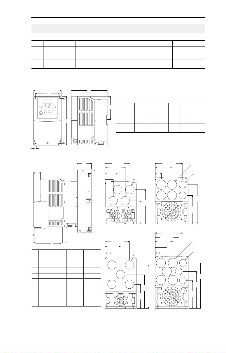
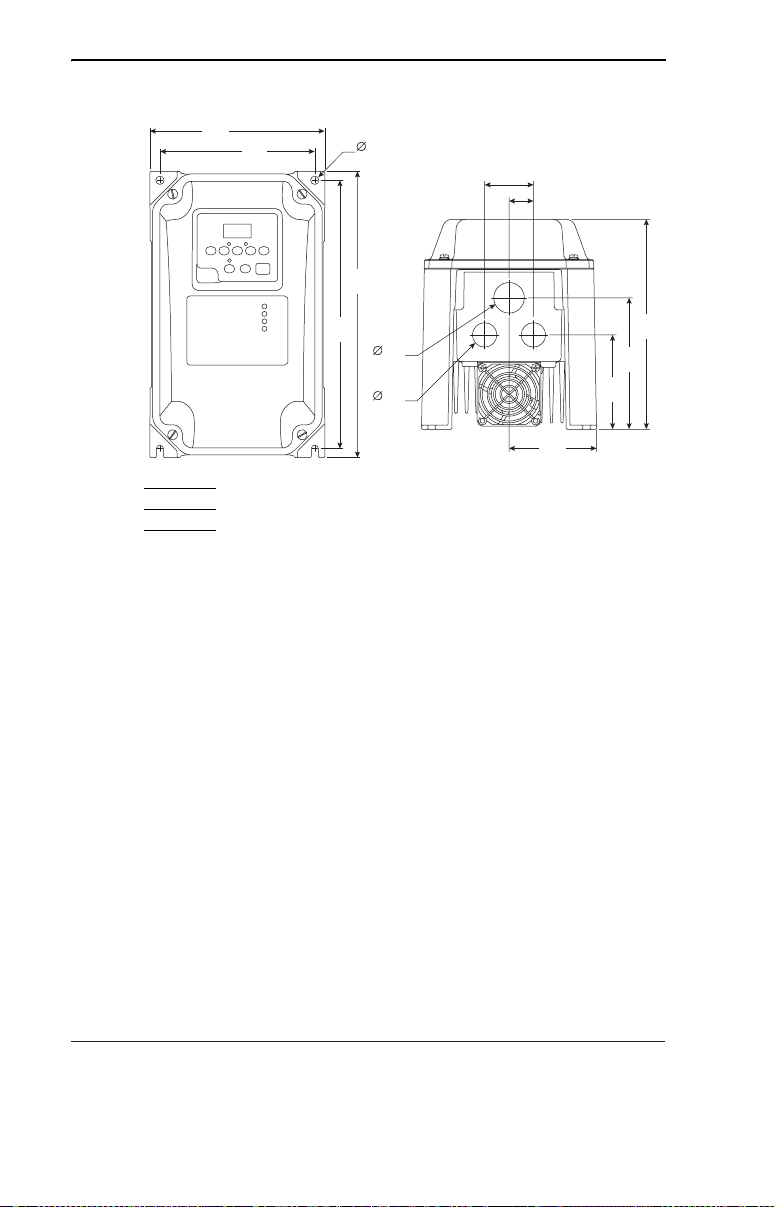
English-21
Drive Dimensions
PowerFlex 40 Frames – Ratings are in kW and (HP)
Frame 120V AC – 1-Phase 240V AC – 1-Phase 240V AC – 3-Phase 480V AC – 3-Phase 600V AC – 3-Phase
B 0.4 (0.5)
0.75 (1.0)
1.1 (1.5)
(1)
C
(1)
IP66, NEMA/UL Type 4X rated drives are not availble in Frame C drive ratings.
IP20, NEMA/UL Type Open
A
D
0.4 (0.5)
0.75 (1.0)
1.5 (2.0)
2.2 (3.0) 5.5 (7.5)
0.4 (0.5)
0.75 (1.0)
1.5 (2.0)
7.5 (10.0)
C
2.2 (3.0)
0.4 (0.5)
2.2 (3.0)
3.7 (5.0)
0.75 (1.0)
1.5 (2.0)
5.5 (7.5)
7.5 (10.0)
0.75 (1.0)
4.0 (5.0)
1.5 (2.0)
2.2 (3.0)
11.0 (15.0) 5.5 (7.5)
7.5 (10.0)
Dimensions are in millimeters and (inches).
Weights are in kilograms and (pounds).
4.0 (5.0)
11.0 (15.0)
E
B
5.5 (0.22)
Communication, RFI Filter, IP 30/NEMA 1/UL Type 1 Option Kits
B
A
C
D
B Frame
Option
Dimension
A Comm Cover 25 (0.98) 25 (0.98)
B EMC Line Filter 50 (1.97) 60 (2.36)
C EMC Line Filter 229 (9.02) 309 (12.17)
D IP30/NEMA 1/UL
Typ e 1
IP30/NEMA 1/UL
Type 1 for Comm
Cover
C Frame
Drive
Drive
33 (1.30) 60 (2.36)
64 (2.52) 60 (2.36)
F
ABCDEF
Frame
B100
(3.94)
C130
(5.1)
79.1 (3.11)
64.1 (2.52)
40.6 (1.60)
25.6 (1.01)
B Frame - 22-JBAB
77.5 (3.05)
50.0 (1.97)
22.5 (0.89)
B Frame - 22-JBCB
(used with Comm Cover)
180
(7.09)
260
(10.2)
∅
(0.87)
74.3
(2.93)
∅
(0.87)
76.3
(3.00)
136
(5.35)87(3.43)
180
(7.1)
22.2
109.9
(4.33)
22.2
134.3
(5.29)
105.3
(4.15)
(used with Comm Cover)
168
87.4
(6.61)
246
(9.7)
(3.44)
–4.3
116
(4.57)
107.0 (4.21)
66.0 (2.60)
24.0 (0.94)
C Frame - 22-JBAC
108.7 (4.28)
92.2 (3.63)
69.2 (2.72)
45.7 (1.80)
22.2 (0.87)
C Frame - 22-JBCC
Ship
Weigh t
2.2
(4.9)
(9.5)
∅
111.2
(4.38)
∅
(5.70)
109.8
(4.32)
(1.12)
∅
152.2
(5.99)
(1.12)
∅
144.8
28.5
22.2
(0.87)
28.5
22.2
(0.87)
179.8
(7.08)
Page 24
English-22
A
A
IP66, NEMA Type/UL Type 4X – Dimensions are in millimeters and (inches) Weights are
in kilograms and (pounds).
165
(6.50)
Weight
5.2 (11.5)
146
(5.75)
253
(9.96)
270
(10.63)
6.5
(0.26)
28
(1.10)
22
(0.87)
46
(1.81)
23
(0.91)
82.5
(3.25)
89
(3.50)
124
(4.88)
198
(7.80)
www.rockwellautomation.com
Power, Control and Information Solutions Headquarters
mericas: Rockwell Automation, 1201 South Second Street, Milwaukee, WI 53204-2496 USA, Tel: (1) 414.382.2000, Fax: (1) 414.382.4444
Europe/Middle East/Africa: Rockwell Automation, Vorstlaan/Boulevard du Souverain 36, 1170 Brussels, Belgium, Tel: (32) 2 663 0600, Fax: (32) 2 663 0640
sia Pacific: Rockwell Automation, Level 14, Core F, Cyberpor t 3, 100 Cyberport Road, Hong Kong, Tel: (852) 2887 4788, Fax: (852) 2508 1846
Publication 22B-QS001F-EN-P – December 2008
Supersedes May 2008 Copyright © 2008 Rockwell Automation, Inc. All rights reserved.
Page 25
Kurzanleitung
Frequenzumrichter
PowerFlex 40
FRN 5.xx - 6.xx
In dieser Kurzanleitung wird beschrieben, wie Sie den Frequenzumrichter
PowerFlex 40 installieren, in Betrieb nehmen und programmieren. Die hierin
enthaltenen Informationen sind jedoch kein
Benutzerhandbuch und sind nur für qualifiziertes FU-Wartungspersonal
vorgesehen.
Genauere Informationen über den PowerFlex 40, einschließlich EMV-Hinweise,
Anwendungsaspekte und die entsprechenden sicherheitstechnischen Hinweise,
finden Sie im PowerFlex 40-Benutzerhandbuch, Publikation 22B-UM001…,
www.rockwellautomation.com/literature.
unter
Allgemeine Vorsichtshinweise
ACHTUNG: Der FU enthält Hochspannungskondensatoren, die sich erst nach
gewisser Zeit nach der Trennung vom Netz entladen. Vor Arbeiten am
Frequenzumrichter muss sichergestellt werden, dass die Netzspannung von den
!
Netzanschlüssen [R, S, T (L1, L2, L3)] getrennt ist. Warten Sie drei Minuten, bis
die Kondensatoren sich auf eine ungefährliche Spannung entladen haben.
Nichtbeachtung kann schwere oder tödliche Verletzungen zur Folge haben.
Eine dunkle LED-Anzeige bedeutet nicht, dass sich die Kondensatoren auf eine
ungefährliche Spannung entladen haben.
ACHTUNG: Die sachwidrige Verwendung des Parameters A092 [Fhl
Neustartvers] oder A094 [Autostart] kann zu Schäden am Gerät und/oder
Verletzungen führen. Diese Funktionen sind nur unter Beachtung der lokal,
!
national und international geltenden Gesetze, Standards, Vorschriften und der in
der Industrie geltenden Bestimmungen anzuwenden.
ACHTUNG: Die Planung und Ausführung der Installation sowie die
Inbetriebnahme und spätere Wartung des Systems sollten nur von qualifiziertem
Fachpersonal ausgeführt werden, das mit Frequenzumrichtern und den daran
!
angeschlossenen Maschinen vertraut ist. Zuwiderhandlungen können zu
Personen- und/oder Sachschäden führen.
ACHTUNG: Dieser FU enthält Teile und Baugruppen, die empfindlich auf
elektrostatische Entladung reagieren. Bei der Installation, Prüfung, Wartung
oder Reparatur des Geräts müssen daher Vorsichtsmaßnahmen getroffen werden,
!
die solch eine elektrostatische Entladung verhindern, da Komponenten
andernfalls beschädigt werden können. Sollten Sie mit dem Verfahren zur
Verhinderung statischer Entladung nicht vertraut sein, ziehen Sie die
A-B-Publikation 8000-4.5.2, „Guarding Against Electrostatic Damage“ oder ein
entsprechendes Handbuch heran.
ACHTUNG: Wird ein FU nicht ordnungsgemäß eingesetzt bzw. installiert,
können Komponenten beschädigt und die Lebensdauer des Produkts dadurch
verkürzt werden. Verdrahtungs- bzw. Anwendungsfehler wie unzureichende
!
Motorgröße, falsche oder unzureichende Netzversorgung und zu hohe
Umgebungstemperaturen können zu Fehlfunktionen im System führen.
Ersatz für das
Page 26
Deutsch-2
Erläuterungen zum Aufstellen des FU
• Befestigen Sie den FU aufrecht an einer flachen, senkrechten und
ebenen Fläche.
Baugröße Schraubengröße Anzugsmoment DIN-Schiene
B M4 (#8-32) 1,56–1,96 Nm 35 mm
C M5 (#10-24) 2,45–2,94 Nm –
B (IP66,
Typ 4X)
• Kühlgebläse vor Staub und Metallpartikeln schützen.
• Keiner korrosiven Umgebung aussetzen.
• Vor Feuchtigkeit und direktem Sonnenlicht schützen.
Beim Aufstellen zu beachtende Mindestabstände
Einbauabmessungen finden Sie auf Seite 23.
M6 (#12-24) 3,95–4,75 Nm –
120 mm
(4.7 in.)
120 mm
(4.7 in.)
25 mm
(1.0 in.)
Nächstes Objekt, das
den Luftstrom durch
den Kühlkörper und
das Gehäuse des FU
blockieren könnte
120 mm
(4.7 in.)
Befestigungsoption A
Kein Abstand zwischen
den FUs erforderlich.
120 mm
(4.7 in.)
Befestigungsoption B
Umgebungs-/Betriebstemperatur
Umgebungstemperatur Schutzart Beim Aufstellen zu
Minimum Maximum
IP20, NEMA/UL-Typ „offen“
40 °C
IP66, NEMA/UL-Typ 4X
–10 °C
IP30, NEMA/UL-Typ 1
50 °C IP20, NEMA/UL-Typ „offen“
(1)
Nennwert erfordert die Installation des PowerFlex 40-Optionskits IP 30,
NEMA/UL-Typ 1.
beachtende
Mindestabstände
Befestigungsoption A
verwenden
Befestigungsoption A
verwenden
Befestigungsoption B
(1)
verwenden
Befestigungsoption B
verwenden
Page 27
Allgemeine Voraussetzungen für die Erdung
Deutsch-3
R/L1
S/L2
T/L3
SHLD
U/T1
V/T2
W/T3
Entfernen von MOVs
Um Schäden am FU zu vermeiden, sollte die MOV-Verbindung zur
Erde bei Installation des FU in einem nicht geerdeten
Verteilungssystem, in dem die Nennspannung zwischen einer der
Phasen 125 % des Phase-Phase-Potenzials übersteigen könnten,
unterbrochen werden. Dazu sind die in den nachstehenden Abbildungen
aufgeführten Brücken zu entfernen.
1. Zum Lösen der Schraube, diese gegen den Uhrzeigersinn drehen.
2. Brücke abziehen und aus dem FU-Gehäuse enfernen.
3. Schraube fest ziehen.
Brückenposition
IP66, NEMA/UL-Typ 4XIP20, NEMA/UL-Typ „offen“
Wichtig: Schraube nach dem Entfernen der Brücke fest ziehen.
Phase-Erde-MOV – Entfernung
AC Input
R/L1
S/L2
T/L3
Jumper
123
Three-Phase
4
Page 28

Deutsch-4
Einhaltung der EU-Richtlinien
Einzelheiten zur Einhaltung der Niederspannungs- und der EMV-Richtlinie
finden Sie im PowerFlex 40-Benutzerhandbuch
.
Sicherungen und Leistungsschalter – Technische Daten
FU-Nennwerte
Ausgangs-
(1)
nennwerte
kW (HP) A
Bestellnummer
100–120 V AC (±10 %) – Einphaseneingang, 0–230-V-Dreiphasenausgang
22B-V2P3x104 0,4 (0,5) 2,3 90–132 1,15 9,0 15 140M-C2E-C16 100-C12 40
22B-V5P0x104 0,75 (1,0) 5,0 90–132 2,45 20,3 35 140M-D8E-C20 100-C23 60
22B-V6P0x104 1,1 (1,5) 6,0 90–132 3,0 24,0 40 140M-F8E-C32 100-C37 80
200–240 V AC (±10 %) – Einphaseneingang
22B-A2P3x104 0,4 (0,5) 2,3 180–264 1,15 6,0 10 140M-C2E-B63 100-C09 40
22B-A5P0x104 0,75 (1,0) 5,0 180–264 2,45 12,0 20 140M-C2E-C16 100-C12 60
22B-A8P0x104 1,5 (2,0) 8,0 180–264 4,0 18,0 30 140M-D8E-C20 100-C23 85
22B-A012x104 2,2 (3,0) 12,0 180–264 5,5 25,0 40 140M-F8E-C32 100-C37 125
200–240 V AC (±10 %) – Dreiphaseneingang, 0–230-V-Dreiphasenausgang
22B-B2P3x104 0,4 (0,5) 2,3 180–264 1,15 2,5 6 140M-C2E-B40 100-C07 40
22B-B5P0x104 0,75 (1,0) 5,0 180–264 2,45 5,7 10 140M-C2E-C10 100-C09 60
22B-B8P0x104 1,5 (2,0) 8,0 180–264 4,0 9,5 15 140M-C2E-C16 100-C12 85
22B-B012x104 2,2 (3,0) 12,0 180–264 5,5 15,5 25 140M-C2E-C16 100-C23 125
22B-B017x104 3,7 (5,0) 17,5 180–264 8,6 21,0 30 140M-F8E-C25 100-C23 180
22B-B024x104 5,5 (7,5) 24,0 180–264 11,8 26,1 40 140M-F8E-C32 100-C37 235
22B-B033x104 7,5 (10,0) 33,0 180–264 16,3 34,6 60 140M-G8E-C45 100-C60 305
380–480 V AC (±10 %) – Dreiphaseneingang, 0–460-V-Dreiphasenausgang
22B-D1P4x104 0,4 (0,5) 1,4 342–528 1,4 1,8 3 140M-C2E-B25 100-C07 35
22B-D2P3x104 0,75 (1,0) 2,3 342–528 2,3 3,2 6 140M-C2E-B40 100-C07 50
22B-D4P0x104 1,5 (2,0) 4,0 342–528 4,0 5,7 10 140M-C2E-B63 100-C09 70
22B-D6P0x104 2,2 (3,0) 6,0 342–528 5,9 7,5 15 140M-C2E-C10 100-C09 100
22B-D010x104 4,0 (5,0) 10,5 342–528 10,3 13,0 20 140M-C2E-C16 100-C23 160
22B-D012x104 5,5 (7,5) 12,0 342–528 11,8 14,2 25 140M-D8E-C20 100-C23 175
22B-D017x104 7,5 (10,0) 17,0 342–528 16,8 18,4 30 140M-D8E-C20 100-C23 210
22B-D024x104 11,0 (15,0) 24,0 342–528 23,4 26,0 50 140M-F8E-C32 100-C43 300
460–600 V AC (±10 %) – Dreiphaseneingang, 0–575-V-Dreiphasenausgang
22B-E1P7x104 0,75 (1,0) 1,7 414–660 2,1 2,3 6 140M-C2E-B25 100-C09 50
22B-E3P0x104 1,5 (2,0) 3,0 414–660 3,65 3,8 6 140M-C2E-B40 100-C09 70
22B-E4P2x104 2,2 (3,0) 4,2 414–660 5,2 5,3 10 140M-C2E-B63 100-C09 100
22B-E6P6x104 4,0 (5,0) 6,6 414–660 8,1 8,3 15 140M-C2E-C10 100-C09 160
22B-E9P9x104 5,5 (7,5) 9,9 414–660 12,1 11,2 20 140M-C2E-C16 100-C16 175
22B-E012x104 7,5 (10,0) 12,2 414–660 14,9 13,7 25 140M-C2E-C16 100-C23 210
22B-E019x104 11,0 (15,0) 19,0 414–660 23,1 24,1 40 140M-D8E-C25 100-C30 300
(1)
In den aufgeführten Bestellnummern steht „x“ für den Gehäusetyp. Für alle Gehäusetypen sind
technische Daten verfügbar. FUs mit Nennwerten gemäß IP66, NEMA/UL-Typ 4X, sind nur in Baugröße
B erhältlich.
(2)
200–240 V AC – Einphasen-FUs sind auch mit integriertem EMV-Filter erhältlich. Das
Bestellnummern-Suffix ändert sich von N104 zu N114. Die Filteroption ist für FUs der Schutzart IP66,
NEMA/UL-Typ 4X, nicht erhältlich.
Eingangsnennwerte Netzstromleitungsschutz Verlustleistung
Spannungsbereich kVA A Sicherungen
(2)
, 0–230-V-Dreiphasenausgang
Motorschutzschalter 140M Schütze IP20 offen (W)
Page 29
Deutsch-5
Eingangs-/Ausgangsnennwerte
Ausgangsfrequenz: 0–400 Hz (programmierbar)
Wirkungsgrad: 97,5 % (typisch)
Zulassungen
D
9
E
6
T
6
S
X
I
L
U
UL508C
L
®
I
N
Q
D
E
C
T
O
N
D
9
E
6
T
6
S
X
I
L
U
CSA 22.2
L
C
®
I
N
Q
D
E
C
T
O
N
EMC Directive 89/336
LV: EN 50178, EN 60204
EMC: EN 61800-3, EN 50081-1
Digitalsteuereingänge (Eingangsstrom = 6 mA) Analogsteuereingänge
SRC-Modus (stromliefernd):
18–24 V = EIN
0–6 V = AUS
SNK-Modus (stromziehend):
0–6 V = EIN
18–24 V = AUS
Analogeingang (4–20 mA): 250 Ohm Eingangsimpedanz
Analogeingang (0–10 V DC): 100 kOhm Eingangsimpedanz
Externer Poti: 1–10 kOhm, 2 W Min.
Steuerausgang
Programmierbarer Ausgang (Relaiskontakt, Form C)
Ohmsche Last: 3,0 A bei 30 V DC, 3,0 A bei 125 V AC, 3,0 A bei 240 V AC
Induktivlast: 0,5 A bei 30 V DC, 0,5 A bei 125 V AC, 0,5 A bei 240 V AC
Optische Ausgänge
30 V DC, 50 mA
Induktionsfrei
Analogausgänge (10 Bit)
0–10 V, 1 kOhm min.
4–20 mA, 525 Ohm max.
Sicherungen und Leistungsschalter
Empfohlener Sicherungstyp: UL-Klasse J, CC, T oder Typ BS88; 600 V (550 V) oder gleichwertig.
Empfohlene Leistungsschalter: HMCP-Leistungsschalter oder gleichwertig.
Schutzvorrichtungen
Motorschutz: I2t-Überlastschutz – 150 % für 60 s, 200 % für 3 s (bietet Schutz der Klasse 10)
Überstrom: 200 % Hardwaregrenze, 300 % Impulsgrenze
Überspannung: 100–120 V AC Eingang – Auslösung bei 405 V DC Busspannung
Unterspannung:100–120 V AC-Eingang – Auslösung bei 210 V DC Busspannung
(entspricht einer Netzeingangsspannung von 150 V AC)
200–240 V AC Eingang – Auslösung bei 405 V DC Busspannung
(entspricht einer Netzeingangsspannung von 290 V AC)
380–460 V AC Eingang – Auslösung bei 810 V DC Busspannung
(entspricht einer Netzeingangsspannung von 575 V AC)
460–600 V AC Eingang – Auslösung bei 1005 V DC Busspannung
(entspricht einer Netzeingangsspannung von 711 V AC)
(entspricht einer Netzeingangsspannung von 75 V AC)
200–240 V AC Eingang – Auslösung bei 210 V DC Busspannung
(entspricht einer Netzeingangsspannung von 150 V AC)
380–480 V AC Eingang – Auslösung bei 390 V DC Busspannung
(entspricht einer Netzeingangsspannung von 275 V AC)
460–600 V AC Eingang –Wenn P042 = 3 erfolgt die Hochspannungsauslösung bei 487 V DC Busspannung
(344 V AC Netzeingangsspannung);
Wenn P042 = 2 erfolgt die Niederspannungsauslösung bei 390 V DC Busspannung
(275 V AC Netzeingangsspannung)
Steuervermögen bei Netzausfall: Minimale Toleranz beträgt 0,5 s – typischer Wert beträgt 2 s
Fehlerfreie Netzausfall-Überbrückung: 100 ms
Dynamischer Brems-Chopper
Alle FUs mit allen Nennwerten sind mit internem Brems-IGBT ausgestattet (ausgenommen Versionen ohne Brems-Chopper).
Bestellinformationen für DB-Widerstände sind Anhang B des PowerFlex 40-Benutzerhandbuchs zu entnehmen.
Page 30

Deutsch-6
Netzanschluss
Verdrahtungsnennwerte Empfohlener Kupferdraht
Nicht abgeschirmt, 600 V, 75 °C THHN/THWN
Abgeschirmt, 600 V, 75 °C oder 90 °C RHH/RHW-2
Abgeschirmter Kabelkanal, 600 V, 75 °C oder 90 °C
RHH/RHW-2
Klemmenblock für den Netzanschluss
B Frame C Frame
V/T2T/L3S/L2R/L1 U/T1 W/T3
DC+
BR+ BR-DC-
(1)
Anschluss
Beschreibung
R/L1, S/L2 1-Phasen-Eingang
R/L1, S/L2, T/L3 3-Phasen-Eingang
U/T1 Zu Motor U/T1
V/T2 Zu Motor V/T2
=
W/T3 Zu Motor W/T3
DC-Bus-Induktoranschluss (nur bei FUs der Baugröße C)
Beim FU der Baugröße C ist bei Anlieferung zwischen den
P2, P1
Klemmen P2 und P1 eine Brücke installiert. Entfernen Sie
diese Brücke nur, wenn ein DC-Bus-Induktor angeschlossen
werden soll. Der FU kann nicht ohne eine angeschlossene
Brücke oder einen angeschlossenen Induktor gestartet werden.
DC+, DC– DC-Busverbindung
BR+, BR– Anschluss des Widerstands für den Brems-Chopper
Schutzerde – PE
(1)
Wichtig: Die Klemmenschrauben können sich während des Transports lösen. Stellen
Sie vor dem Einschalten des FU sicher, dass alle Klemmenschrauben mit dem
empfohlenen Drehmoment angezogen sind.
Klemmenblock für den Netzanschluss – Technische Daten
Baugröße Maximaler
Leiterquerschnitt
2
B 5,3 mm
C 8,4 mm
(2)
Der angegebene Leiterquerschnitt bezeichnet Maximal- bzw. Minimalgrößen, die in
(10 AWG) 1,3 mm2 (16 AWG) 1,7–2,2 Nm
2
(8 AWG) 1,3 mm2 (16 AWG) 2,9–3,7 Nm
Minimaler
(2)
Leiterquerschnitt
den Klemmenblock passen – es handelt sich nicht um Empfehlungen.
0,4 mm, isoliert, für trockene
Standorte
Anixter OLF-7xxxxx,
Belden 29501-29507 oder
gleichwertig
Anixter 7V-7xxxx-3G
Shawflex 2ACD/3ACD oder
gleichwertig
V/T2T/L3S/L2R/L1 U/T1 W/T3 P2 P1
DC+
BR+ BR-DC-
Zwei Motorkabel
vertauschen, um
Drehrichtung zu
ändern.
Drehmoment
(2)
Page 31

Deutsch-7
Netzeigenschaften
Netzeigenschaft Abhilfemaßnahme
Niedrige Leitungsimpedanz
(weniger als 1 % Reaktanz)
Größer als 120-kVA-Netztransformator
Leitung verfügt über
Blindleistungskompensationskondensatoren
Häufige Netzunterbrechungen
Kurzfristige Spannungsspitzen von mehr als
6000 V (Blitzschlag)
Phase-Erde-Spannung überschreitet 125 % der
normalen Phase-Phase-Spannung.
Ungeerdetes Verteilungssystem
Offene Delta-Konfiguration (240 V)
(1)
Für FUs, die in offenen Delta-Konfigurationen mit einem neutralen System eingesetzt
werden, bei dem die mittlere Phase geerdet ist, wird die Phase gegenüber der in der Mitte
der Masse oder Erdung abgenommen Phase als „Hauptzweig“, „Spannungszweig“, „roter
Zweig“ o. Ä. bezeichnet. Dieser Zweig sollte im gesamten System jeweils am
Anschlusspunkt mit rotem oder orangefarbenem Klebeband gekennzeichnet werden. Der
Hauptzweig sollte an der mittlere Phase B der Drossel angeschlossen werden. Die genauen
Artikelnummern der Netzdrosseln sind dem PowerFlex 40-Benutzerhandbuch zu
entnehmen.
(2)
Bestellinformationen für Zubehörteile sind Anhang B des PowerFlex 40-Benutzerhandbuchs
zu entnehmen.
(1)
• Netzdrossel
• oder Trenntransformator
installieren
• oder Businduktor installieren – nur
bei FUs zwischen 5,5 und 11 kW
• Netzdrossel
• oder Trenntransformator
installieren
• MOV-Brücke zu Erde entfernen
• oder Trenntransformator mit
geerdeter Sekundärwicklung
installieren.
• Netzdrossel installieren
(2)
Empfohlene E/A-Verdrahtung
Leiterarten
Belden 8760/9460
(oder gleichw.)
Belden 8770
(oder gleichw.)
(3)
(4)
(4)
Wenn die Kabel kurz sind und sich in einem Schaltschrank befinden, der keine
empfindlichen Schaltungen enthält, ist zwar keine Abschirmung für diese Kabel
erforderlich, jedoch wird diese empfohlen.
Beschreibung Minimale
0,8 mm2(18AWG), verdrillt, 100 %
abgeschirmtes Kabel mit Ableiter
0,8 mm2(18AWG), 3-adrig, abgeschirmt nur für
Fernpoti
Litze oder Volldraht.
(3)
Isolationsspannung
300 V
60 °C
E/A-Klemmenblock – Technische Daten
Baugröße Maximale Leitergröße
(5)
Minimale Leitergröße
B und C 1,3 mm2 (16 AWG) 0,2 mm2 (24 AWG) 0,5–0,8 Nm
(5)
Der angegebene Leiterquerschnitt bezeichnet Maximal- bzw. Minimalgrößen, die in den
Klemmenblock passen – es handelt sich nicht um Empfehlungen.
Empfehlungen zu den maximalen Längen für Netz- und Steuerkabel sind
dem PowerFlex 40-Benutzerhandbuch zu entnehmen.
(5)
Drehmoment
Page 32

Deutsch-8
Steuerein- und Steuerausgänge
Steuerleitungsblockdiagramm
(4)
Enable
Jumper
Relay N.O.
Relay Common
Relay N.C.
Ohmscher
Widerstand
Induktiv 0,5 A 0,5 A 0,5 A
P036 [Startquelle] Stopp E/A-Klemme 01 Stopp
RS485-Anschluss Über P037 Auslauf
R1
R2
R3
0-10V
0-20mA
R1 R2 R3
30 V DC 125 V AC 240 V AC
3,0 A 3,0 A 3,0 A
Tastatur Über P037 Auslauf
3-Draht Über P037 Über P037
2-Draht Über P037 Auslauf
SNK
SRC
SRCSNK
+24V
+10V
0-10V
0/4-20mA
30V DC
50mA
Non-inductive
Analog Output Select
01 02 03 04 05
11 12 13 14 15
(1)
(1)
Wichtig: An E/A-Klemme 01 erfolgt nur dann kein Auslauf,
wenn P036 [Startquelle] auf „3-Draht“-Steuerung oder
„MomVW/RWStrg“ eingestellt ist. Bei der 3-Draht-Steuerung
wird E/A-Klemme 01 über P037 [Stoppmodus] gesteuert. Alle
weiteren Stoppquellen werden über P037 [Stoppmodus]
gesteuert.
(1)(4)
Stop
01
Start/Run FWD
02
Direction/Run REV
03
Digital Common
04
Digital Input 1
05
Digital Input 2
06
Digital Input 3
07
Digital Input 4
08
Opto Common
09
+24V DC
11
+10V DC
12
0-10V (or ±10V) Input
13
Analog Common
14
4-20mA Input
15
Analog Output
16
Opto Output 1
17
Opto Output 2
18
RS485 Shield
19
ENBL
06 07 08 09
16 17 18 19
Typical
SRC Wiring
(2)
Enable
Jumper
Pot must be
1-10k ohm
2 Watt Min.
Common
(4)
RS485
(DSI)
Typical
SNK Wiring
(3)
24V
1
Wichtig: Bei Anlieferung des FU ist zwischen E/A-Klemme 01 und 11 eine Brücke installiert. Wenn E/A-Klemme
01 als Stopp- oder Aktivierungseingang verwendet wird, muss diese Brücke entfernt werden.
(2)
Hier 2-Draht-Steuerung. Bei der 3-Draht-Steuerung ist an E/A-Klemme 02 ein einmaliger Befehl für einen
Start erforderlich. Zur Richtungsänderung an E/A-Klemme 03 ist ein Dauerbefehl erforderlich.
(3)
Bei Verwendung eines Optoausgangs mit einer induktiven Last (z. B. ein Relais) installieren Sie eine
Seriendiode parallel zum Relais (siehe Abbildung), um Schäden am Ausgang zu vermeiden.
(4)
Wenn die ENBL-Brücke entfernt ist, fungiert die E/A-Klemme 01 immer als Hardwareaktivierung und bewirkt
einen Auslauf. Weitere Informationen dazu finden Sie im PowerFlex 40-Benutzerhandbuch.
Page 33

Deutsch-9
Steuerungs-E/A-Klemmenbezeichnungen
Nr. Signal Werkseinstellung Beschreibung Param.
R1 Schließerrelais Fehler Schließerkontakt für Ausgangsrelais A055
R2 Relais-
Bezugspotenzial
R3 Öffnerrelais Fehler Öffnerkontakt für Ausgangsrelais A055
– Ausgangsrelais-Bezugspotenzial
Anwahl-DIP-Schalter
für Analogausgang
DIP-Schalter für
stromziehend/stromliefernd
01 Stopp
02 Start/Vorwärtslauf Nicht aktiv Befehl wird standardmäßig über die integrierte
03 Richtung/
04 Digital-
05 Digitaleingang 1 Voreinst Freq Mit A051 [Wahl Dig. Eing1] programmieren. A051
06 Digitaleingang 2 Voreinst Freq Mit A052 [Wahl Dig. Eing2] programmieren. A052
07 Digitaleingang 3 Lokal Mit A053 [Wahl Dig. Eing3] programmieren. A053
08 Digitaleingang 4 Tipp vor Mit A054 [Wahl Dig. Eing4] programmieren. A054
09 Opto-
11 +24 V DC – Bezug auf Digital-Bezugspotenzial.
12 +10 V DC – Bezug auf Analog-Bezugspotenzial.
13 ±10 V Eingang
14 Analog-
15 4–20 mA Eingang
16 Analogausgang Ausg.freq 0–10 Der standardmäßige Analogausgang ist 0–10 V.
(1)
Rückwärtslauf
Bezugspotenzial
Bezugspotenzial
Bezugspotenzial
0–10 V Stellt den Analogausgang auf Spannung oder Strom ein. Diese
Stromliefernd (SRC) Eingänge können über die DIP-Schaltereinstellung als
Auslauf Die werkseitig installierte Brücke oder ein
Nicht aktiv P036, P037,
– Für Digitaleingänge. Durch Digitaleingänge von
– Für optisch gekoppelte Ausgänge. Durch
(2)
Nicht aktiv Für externe 0–10 V- (unipolare) oder ±10-V-
– Für 0–10-V-Eing. oder 4–20-mA-Eing. Durch
(2)
Nicht aktiv Für externe 4–20-mA-Eingangsversorgung
Einstellung muss mit A065 [Wahl Anlg. Ausg.] übereinstimmen.
stromziehend (SNK) oder stromliefernd (SRC) verdrahtet werden.
Öffnereingang müssen vorhanden sein, um den
FU zu starten.
Tastatur eingegeben. Zur Deaktivierung des
Rückwärtslaufs siehe A095 [Rückw deak].
Analog-E/A und Optoausgängen elektronisch
getrennt.
Optoausgänge von Analog-E/A und
Digitaleingängen elektronisch getrennt.
FU liefert Strom für Digitaleingänge.
Maximaler Ausgangsstrom beträgt 100 mA.
FU liefert Strom für externes 0–10-VPotenziometer.
Maximaler Ausganggstrom beträgt 15 mA.
(bipolare) Eingangsversorgung
(Eingangsimpedanz = 100 kOhm) oder
Potenziometeranschluss.
Analogein- und ausgänge von Digital-E/A und
Optoausgängen elektronisch getrennt.
(Eingangsimpedanz = 250 Ohm).
Zum Konvertieren in einen Stromwert stellen Sie
den Analogsausgangs-Anwahl-DIP-Schalter auf
0–20 mA. Mit A065 [Wahl Anlg. Ausg.]
programmieren. Der maximale Analogwert kann
mit A066 [Anlg. Ausg. OG] skaliert werden.
Maximallast: 4–20 mA = 525 Ohm (10,5 V)
0–10 V = 1 kOhm (10 mA)
P036
P036, P037
A095
P038
P038,
A051–A054,
A123, A132
P038,
A051–A054,
A132
A065, A066
(1)
Page 34

Deutsch-10
Nr. Signal Werkseinstellung Beschreibung Param.
17 Optoausgang 1 Motor läuft Mit A058 [Wahl Optoausg. 1] programmieren. A058, A059,
18 Optoausgang 2 Frequenz erreicht Mit A061 [Wahl Optoausg2] programmieren. A061, A062,
19 RS485-
Abschirmung (DSI)
(1)
Siehe Fußnote (1) und (4) auf Seite 8.
(2)
0–10-V-Eing. und 4–20-mA-Eing. sind zwei verschiedene Eingangskanäle, die gleichzeitig
– Klemme sollte mit dem Massepunkt PE verbunden
sein, wenn der DSI-Kommunikationsport (RS485)
verwendet wird.
angeschlossen werden können.
Diese Eingänge können unabhängig voneinander zur Drehzahlsteuerung oder gemeinsam im
PID-Modus verwendet werden.
A064
A064
Page 35

Deutsch-11
Vorbereitung auf die FU-Inbetriebnahme
ACHTUNG: Legen Sie zunächst Spannung an den FU an, um die im
Folgenden beschriebenen Vorgänge für die Inbetriebnahme durchzuführen.
Im Gerät liegen allerdings Spannungen in der Höhe der Netzspannung an.
!
Zur Vermeidung eines elektrischen Schlags bzw. von Geräteschäden sollten
die folgenden Schritte nur von qualifiziertem Wartungspersonal
durchgeführt werden. Lesen Sie vor der Inbetriebnahme sämtliche
Anweisungen aufmerksam durch. Fahren Sie nicht fort, wenn während der
Durchführung dieser Anweisung ein beschriebenes Ereignis nicht eintritt.
Schalten Sie die Stromversorgung aus, einschließlich aller
anlageninternen Steuerspannungen. Es können anlageninterne Spannungen
anliegen, auch wenn am FU kein Netzstrom anliegt. Beheben Sie die
Betriebsstörung, bevor Sie fortfahren.
Vor dem Einschalten
❏ 1. Stellen Sie sicher, dass sämtliche Eingänge an die korrekten Klemmen
angeschlossen und gesichert sind.
❏ 2. Stellen Sie sicher, dass die anzuschließende Netzspannung innerhalb des
für den FU zulässigen Bereichs liegt.
❏ 3. Stellen Sie sicher, dass die Digitalsteuerspannung 24 V beträgt.
❏ 4. Stellen Sie sicher, dass die DIP-Schaltereinstellung für SNK
(stromziehend)/SRC (stromliefernd) dem Steuerverdrahtungsplan
entspricht. Die Position finden Sie auf Seite 8.
Wichtig: Der voreingestellte Steuerplan lautet stromliefernd (SRC). Die
❏ 5. Stellen Sie sicher, dass der Stoppeingang vorhanden ist, andernfalls wird
der FU nicht gestartet.
Wichtig: Wenn E/A-Klemme 01 als Stoppeingang verwendet wird,
Einschalten des FU
❏ 6. Schalten Sie die Netzspannung und Eingangssteuerspannungen zum FU
ein.
❏ 7. Machen Sie sich mit den Funktionen der integrierten Tastatur (siehe
nächste Seite) vertraut, bevor Sie Parameter der Programm-Gruppe
einstellen.
Stoppklemme ist überbrückt (E/A-Klemme 01 und 11), um den
Start über die Tastatur zu ermöglichen. Wenn der Steuerplan
auf stromziehend (SNK) geändert wird, muss die Brücke von
E/A-Klemme 01 und 11 entfernt und zwischen E/A-Klemme
01 und 04 angebracht werden.
muss die Brücke zwischen E/A-Klemme 01 und 11 entfernt
werden.
Eine entsprechende Erläuterung zu möglicherweise während des
Einschaltvorgangs angezeigten Fehlercodes finden Sie auf Seite 22.
Ausführliche Informationen zur Fehlersuche sind dem PowerFlex
40-Benutzerhandbuch zu entnehmen.
Page 36

Deutsch-12
Start-, Stopp-, Richtungs- und Drehzahl-Steuerung
Der FU kann anhand der werkseitig eingestellten Parameterwerte über
die integrierte Tastatur gesteuert werden. Zum Starten, Stoppen, zur
Richtungsänderung und zur Drehzahlregelung direkt über die integrierte
Tastatur ist keine Programmierung erforderlich.
Wichtig: Zur Deaktivierung des Rückwärtslaufs siehe A095
[Rückw deak].
Ändern des Drehzahlsollwerts eines FUs der Schutzart IP66,
NEMA/UL-Typ 4X
Wenn ein Anzeigegruppe-Parameter, beispielsweise d001
[Ausgangsfreq], angezeigt wird und für P038 [Solldrehzahl] der Wert
A069 [Interne Frequenz] eingestellt ist, können Sie die interne Frequenz
über den Pfeil nach oben bzw. unten ändern.
VOLTS
AMPS
RUN
FWD
REV
PROGRAM
VOLTS
AMPS
HERTZ
FAULT
Beim Anpassen der internen Frequenz wird deren Wert angezeigt, und
die Hertz-LED blinkt. Alle Änderungen werden sofort gespeichert. Die
Anzeige kehrt anschließend zum zuvor angezeigten AnzeigegruppeParameter zurück.
HERTZ
TIPP: Standardmäßig ist der Drehzahlsollwert eines
Frequenzumrichters der Schutzklasse IP66, NEMA/UL-Typ 4X auf die
interne Frequenz gesetzt, also A069 [Interne Frequenz].
TIPP: Sie können den Drehzahlsollwert auch ändern, indem Sie im
Programm-Modus den Parameter A069 [Interne Frequenz] bearbeiten.
Ausführliche Informationen dazu, wie Sie den Programm-Modus
aktivieren, finden Sie im Abschnitt “Anzeigen und Bearbeiten von
Parametern”.
Der Standardwert von A069 [Interne Frequenz] ist 0 Hz. Für PowerFlex
40-Frequenzumrichter der Schutzklasse IP20 lautet der Standardwert
dieses Parameters 60 Hz.
Page 37

Integrierte Tastatur
Deutsch-13
➏
➊
RUN
FWD
REV
➍
➐
PROGRAM
➋
➎
FAULT
➌
VOLTS
AMPS
HERTZ
➑
➒
Menü Beschreibung
Anzeigegruppe (nur zur Anzeige)
Besteht aus häufig angezeigten
FU-Betriebszuständen.
Grundsätzliche Programm-Gruppe
Besteht aus häufig verwendeten programmierbaren
Funktionen.
Erweiterte Programm-Gruppe
Besteht aus den restlichen programmierbaren
Funktionen.
Störung
Besteht aus einer Auflistung von Codes für
bestimmte Fehlerzustände. Wird nur dann
angezeigt, wenn ein Fehler vorliegt.
Nr. LED LED-Zustand Beschreibung
Betriebs-/
➊
Richtungsstatus
Alphanumerische
➋
Anzeige
Anzeigeeinheiten Stetig rot Zeigt die Einheiten des angezeigten Parameterwerts an.
➌
Programmstatus Stetig rot Zeigt an, dass Parameterwerte geändert werden können.
➍
Fehlerstatus Blinkt rot Es liegt ein FU-Fehler vor.
➎
Poti-Status Stetig grün Potenziometer der integrierten Tastatur ist aktiviert.
➏
Start-Tastenstatus Stetig grün Start-Taste der integrierten Tastatur ist aktiviert.
➐
Stetig rot FU läuft und Motordrehung erfolgt in Sollrichtung.
Blinkt rot FU hat einen Befehl zum Richtungswechsel erhalten. Zeigt
die tatsächliche Motordrehrichtung während der
Verzögerung auf null an.
Stetig rot Zeigt Parameternummer, Parameterwert oder Fehlercode
Blinkt rot Wenn eine Ziffer blinkt, kann diese bearbeitet werden.
an.
Wenn alle Ziffern blinken, liegt eine Störung vor.
Richtungswechsel-Taste ist ebenfalls aktiviert, sofern sie
nicht über A095 [Rückw deak] deaktiviert wurde.
(1)
Nr. Taste Bezeichnung Beschreibung
➑
Escape Im Programmiermenü einen Schritt zurückgehen.
Die Änderung eines Parameterwerts abbrechen und den
Programm-Modus verlassen.
Select Im Programmiermenü einen Schritt weitergehen.
Pfeil nach oben
Pfeil nach unten
Eingabe Im Programmiermenü einen Schritt weitergehen.
Bei der Anzeige eines Parameterwerts eine Ziffer
auswählen.
Bildlauf durch Gruppen und Parameter durchführen.
Den Wert einer blinkenden Ziffer erhöhen/verringern.
Dient nur dann zum Anpassen der internen Frequenz von
Frequenzumrichtern der Schutzklasse IP66, NEMA/UL Typ
4X, wenn ein Anzeigegruppe-Parameter angezeigt wird und
für P038 [Solldrehzahl] die interne Frequenz, A069 [Interne
Frequenz], eingestellt wurde.
Eine Änderung an einem Parameterwert speichern.
Page 38

Deutsch-14
Nr. LED LED-Zustand Beschreibung
➒
(1)
FUs der Schutzart P66, NEMA/UL-Typ 4X, sind nicht mit Potenziometern ausgestattet.
Potenziometer
Start Dient zum Starten des FU. Standardmäßig aktiviert.
Umpolen Dient zur Änderung der FU-Richtung. Standardmäßig
Stopp Dient zum Stoppen des FU oder zum Löschen eines
(1)
Dient zur Steuerung der FU-Drehzahl. Standardmäßig
aktiviert.
Über Parameter P038 [Solldrehzahl] gesteuert.
Über Parameter P036 [Startquelle] gesteuert.
aktiviert.
Über Parameter P036 [Startquelle] und A095 [Rückw deak]
gesteuert.
Fehlers.
Diese Taste ist immer aktiviert.
Über Parameter P037 [Stoppmodus] gesteuert.
Page 39

Weitere Informationen zu Parametern finden Sie im PowerFlex 40-Benutzerhandbuch.
Deutsch-15
Anzeigen und Bearbeiten von Parametern
Beim Abschalten wird der zuletzt vom Benutzer gewählte Anzeige-Gruppe-Parameter gespeichert.
Dieser wird standardmäßig beim nächsten Einschalten angezeigt.
Es folgt ein Beispiel grundlegender Funktionen der integrierten Tastatur und der Anzeige. Dieses
Beispiel enthält grundlegende Navigationsanweisungen und veranschaulicht, wie der erste Parameter
der Programm-Gruppe programmiert wird.
Schritt Tasten Beispielanzeigen
1. Bein Einschalten wird der vom Benutzer zuletzt
gewählte Parameter der Anzeige-Gruppe in
blinkenden Zeichen kurz angezeigt. Anschließend
wechselt die Anzeige zum aktuellen Wert dieses
Parameters. (Im Beispiel wird der Wert von d001
[Ausgangsfreq] bei gestopptem FU angezeigt.)
2. Drücken Sie Esc einmal, um die beim Einschalten
eingeblendete Parameternummer der Anzeige-Gruppe
aufzurufen. Nun blinkt die Parameternummer.
3. Drücken Sie Esc erneut, um das Gruppenmenü
aufzurufen. Der Gruppenmenü-Buchstabe blinkt.
4. Drücken Sie den Pfeil nach oben bzw. den Pfeil nach
unten, um einen Bildlauf durch das Gruppenmenü
(d, P und A) durchzuführen.
5. Drücken Sie zum Eingeben einer Gruppe die Eingabeoder die Sel-Taste. Nun blinkt die rechte Ziffer des
zuletzt angezeigten Parameters dieser Gruppe.
6. Drücken Sie den Pfeil nach oben bzw. den Pfeil nach
unten, um einen Bildlauf durch die in der Gruppe
enthaltenen Parameter durchzuführen.
7. Drücken Sie die Eingabe- oder die Sel-Taste, um den
Wert eines Parameters einzublenden. Wenn der Wert
nicht bearbeiten werden soll, kehren Sie durch
Drücken der Esc-Taste zur Parameternummer zurück.
oder
oder
oder
oder
VOLTS
AMPS
HERTZ
FAULTPROGRAM
VOLTS
AMPS
HERTZ
FAULTPROGRAM
VOLTS
AMPS
HERTZ
FAULTPROGRAM
VOLTS
AMPS
HERTZ
FAULTPROGRAM
VOLTS
AMPS
HERTZ
FAULTPROGRAM
8. Drücken Sie die Eingabe- oder die Sel-Taste, um zum
Bearbeiten des Parameterwerts den
Programm-Modus aufzurufen. Die rechte Ziffer blinkt
und die Programm-LED leuchtet, wenn der Parameter
bearbeitet werden kann.
9. Drücken Sie zum Ändern des Parameterwerts den
Pfeil nach oben bzw. den Pfeil nach unten. Bei Bedarf
können Sie mit der Sel-Taste von Ziffer zu Ziffer bzw.
Bit zu Bit wechseln. Die Ziffer bzw. das Bit, das
geändert werden kann, blinkt.
10. Drücken Sie die Esc-Taste, um eine Änderung
abzubrechen. Die Ziffer hört nun auf zu blinken, der
vorhergehende Wert wird wiederhergestellt und die
Programm-LED erlischt.
Oder
Drücken Sie zum Speichern einer Änderung die
Eingabetaste. Die Ziffer hört nun auf zu blinken und
die Programm-LED erlischt.
11. Drücken Sie die Esc-Taste, um zur Parameterliste
zurückzukehren. Drücken Sie die Esc-Taste, bis das
Programmiermenü ausgeblendet wird.
Wenn sich die Anzeige bei Betätigung der Esc-Taste
nicht verändert, wird d001 [Ausgangsfreq] angezeigt.
Drücken Sie die Eingabe- oder die Sel-Taste, um das
Gruppenmenü aufzurufen.
oder
oder
VOLTS
AMPS
HERTZ
FAULTPROGRAM
VOLTS
AMPS
HERTZ
FAULTPROGRAM
VOLTS
AMPS
HERTZ
FAULTPROGRAM
Page 40

Deutsch-16
Weitere Informationen zu Parametern finden Sie im PowerFlex 40-Benutzerhandbuch.
Die grundsätzliche Programm-Gruppe enthält die am häufigsten geänderten Parameter.
Parameter der Anzeige-Gruppe
Nr. Parameter Min./Max. Anzeige/Optionen
d001 [Ausgangsfreq] 0,0/[Maximalfrequenz] 0,1 Hz
d002 [Frequenzsollwert] 0,0/ [Maximalfrequenz] 0,1 Hz
d003 [Ausgangsstrom] 0,00/(FU-Strom A × 2) 0,01 A
d004 [Ausgangsspannung] 0/FU-Nennspannung 1 V AC
d005 [DC-Busspannung] Basierend auf
d006 [Gerätestatus] 0/1 (1 = Zustand wahr) Bit 3
d007–
[Code Störung x] F2/F122 F1
d009
d010 [Prozessanzeige] 0,00/9999 0,01–1
d012 [Steuerquelle] 0/9 Ziffer 1 = Drehzahlsollwer t
d013 [Steuereing Stat.] 0/1 (1 = Eingang aktuell) Bit 3
d014 [Dig.Eing. Status] 0/1 (1 = Eingang aktuell) Bit 3
d015 [Komm. Status] 0/1 (1 = Zustand wahr) Bit 3
d016 [Regler-SW Vers.] 1,00/99,99 0,01
d017 [Gerätetyp] 1001/9999 1
d018 [Betriebszeit] 0/9999 Std. 1=10 Std.
d019 [Testpunkt Daten] 0/FFFF 1 hexadezimal
d020 [Anlg Eing 0–10 V] 0,0/100,0 % 0,1 %
d021 [Anlg Eing 4–20 mA] 0,0/100,0 % 0,1 %
d022 [Ausgangsleistung] 0,00/(FU-Leistung × 2) 0,01 kW
d023 [Ausg-Leistungsf.] 0,0/180,0 Grad 0,1 Grad
d024 [Gerätetemp.] 0/120 °C 1 °C
d025 [Zählerstatus] 0/9999 1
d026 [Timerstatus] 0,0/9999 s 0,1 s
d028 [Stp Logic Status] 0/7 1
d029 [Wirkstrom] 0,00/(FU-Strom A × 2) 0,01 A
FU-Nennspannung
1 V DC
Verzögerung Beschleunigung Vorwärts Betrieb
(Siehe P038; 9 = „Tippfreq.“) (Siehe P036; 9 = „Tippbetrieb“)
DB-Trans.ein Stopp-Eing. Richt/RW Ein Strt/VW Eing
Dig. Eing. 4 Dig. Eing. 3 Dig. Eing. 2 Dig. Eing. 1
Fehler DSI Tx Rx
Bit 2 Bit 1 Bit 0
Ziffer 0 = Startbefehl
Bit 2 Bit 1 Bit 0
Bit 2 Bit 1 Bit 0
Bit 2 Bit 1 Bit 0
Page 41

Weitere Informationen zu Parametern finden Sie im PowerFlex 40-Benutzerhandbuch.
Deutsch-17
Schnell-Inbetriebnahme mit den wichtigsten
Parametern der Programm-Gruppe
Der PowerFlex 40 ist für eine schnelle und problemlose Inbetriebnahme konzipiert. Die
Programm-Gruppe enthält die am meisten verwendeten Parameter.
= Bevor dieser Parameter geändert wird, muss der FU gestoppt werden.
Nr. Parameter Min./Max. Anzeige/Optionen Werkseinstellung
P031 [Motornennspg.] 20/FU-Nennspannung 1 V AC Basierend auf
Eingestellt auf die Nennspannung des Motors
(Typenschild).
P032 [Motnennfreq.] 15/400 Hz 1 Hz 60 Hz
Eingestellt auf die Nennfrequenz des Motors
(Typenschild).
P033 [Überlaststrom] 0,0/(FU-Nennstrom A × 2) 0,1 A Basierend auf
Auf den maximal zulässigen Motorstromwert
einstellen.
P034 [Minimalfrequenz] 0,0/400,0 Hz 0,1 Hz 0,0 Hz
Legt die niedrigste kontinuierliche
Ausgangsfrequenz des FU fest.
P035 [Maximalfrequenz] 0/400 Hz 1 Hz 60 Hz
Legt die höchste Ausgangsfrequenz des FU fest.
P036 [Start Source] 0/6 0 = „Tastatur“
Stellt den zum Starten des FU verwendeten
Steuerplan ein.
(1)
Im aktivierten Zustand ist die
Richtungswechsel-Taste ebenfalls aktiviert,
sofern sie nicht mit A095 [Rückw deak]
deaktiviert wurde.
P037 [Stop Mode] 0/9 0 = „Rampe, CF“
Aktiver Stoppmodus für alle Stoppquellen [z. B.
Tastatur, Vorwärtslauf (E/A-Klemme 02),
Rückwärtslauf (E/A-Klemme 03), RS485Anschluss], wobei die unten aufgeführten
Ausnahmen zutreffen.
Wichtig: An E/A-Klemme 01 erfolgt nur dann kein
Auslauf, wenn P036 [Startquelle] auf “3-Draht”
eingestellt ist. Bei der 3-Draht-Steuerung wird
E/A-Klemme 01 über P037 [Stoppmodus]
gesteuert.
P038 [Speed Reference] 0/7 0 = „FU-Pot“
Stellt die Drehzahlsollwert-Quelle des FU ein.
Wichtig: Wenn A051 oder A052 [Wahl Dig. Eingx]
auf Option 2, 4, 5, 6, 13 oder 14 eingestellt ist und
der Digitaleingang aktivier t ist, übersteuern A051,
A052, A053 bzw. A054 den durch diesen
Parameter festgelegten Drehzahlsollwert. Weitere
Informationen finden Sie in Kapitel 1 des
PowerFlex 40-Benutzerhandbuchs.
P039 [Beschl-Zeit 1] 0,0/600,0 s 0,1 s 10,0 s
Definiert die Zeit, die der FU für die
Beschleunigung auf sämtliche Frequenzen
benötigt.
P040 [Verzög-Zeit 1] 0,1/600,0 s 0,1 s 10,0 s
Definiert die Zeit, die der FU für Verzögerungen
benötigt.
P041 [Reset Werkseinst] 0/1 0 = „Bereit/Inakt“
Setzt die Werte aller Parameter auf die
Werkseinstellung zurück.
P042 [Spannungsklasse] 2/3
Legt die Spannungsklasse der FUs mit 600 V fest.
P043 [MtrUel-Spei] 0/1 0 = „AUS“
Aktiviert/deaktiviert die Funktion zur Motorüberlastspeicherung.
1 = „3-Draht“
2 = „2-Draht“
3 = „2-W PegSens“
4 = „2-W Ho Drehz“
5 = „COM-Port“
6 = „MomVW/RWStrg“
1 = „Auslauf, CF“
2 = „DC-Bremse CF“
3 = „DCBrAuto,CF“
4 = „Rampe“
5 = „Auslauf“
6 = „DC-Bremse“
7 = „DC-Br Auto“
8 = „Rmp+EMBSg,FQ“
9 = „Rmp+EMB-Strg“
(1)
1 = „Int Frequ“
2 = „0–10 V Eing“
3 = „4–20 mA Eing“
4 = „Eingest Freq“
5 = „COM-Port“
6 = „Stp Logik“
7 = „AlgEingMulti“
1 = „Rücks Std“
2 = „Niedersp“ (480 V)
3 = „Hochsp“ (600 V)
1 = „Freigabe“
(1)
(1)
(1)
(1)
(1)
Stoppeingang löscht auch aktiven
Fehler.
FU-Nennspannung
FU-Nennspannung
0
0
0
1 (IP66, Typ 4X)
0
3
0
Page 42

Deutsch-18
Weitere Informationen zu Parametern finden Sie im PowerFlex 40-Benutzerhandbuch.
Erweiterte Parametergruppe
Nr. Parameter Min./Max. Anzeige/Optionen Werkseinstellung
[Wahl Dig. Eing1]
A051
E/A-Klemme 05
[Wahl Dig. Eing2]
A052
E/A-Klemme 06
[Wahl Dig. Eing3]
A053
E/A-Klemme 07
[Wahl Dig. Eing4]
A054
E/A-Klemme 08
Wichtig: Die Solldrehzahl für FUs der
Schutzart IP66, NEMA/UL-Typ 4X,
wird durch A069 [Interne Frequenz]
vorgegeben.
A055 [Wahl Relaisausg] 0/24 0 = „Ber/Fehler“
A056 [Ebene Relaisausg] 0,0/9999 0,1 0,0
A058
[Wahl Optosausg1]
A061
[Wahl Optosausg2]
A059
[Ebene Optoausg1]
A062
[Ebene Optoausg2]
Einstellung A055, A058,
A061
6 0/400 Hz
7 0/180 %
8 0/815 V
10 0/100 %
16 0,1/9999 s
17 1/9999 Zählwerte
18 1/180 Grad
20 0/1
23 0/400 Hz
A064 [Optoausg. Logik] 0/3 1 0
A064-Option Optoausg.1 Logik Optoausg.2 Logik
0 NO (Schließer) NO (Schließer)
1 NC (Öffner) NO (Schließer)
2 NO (Schließer) NC (Öffner)
3 NC (Öffner) NC (Öffner)
0/27 0 = „Nicht verw.“
1 = „Besch/Verz 2“
2 = „Tippen“
3 = „Ext. Fehler“
4 = „Eingest Freq“
(1)
5 = „Lokal“
6 = „COM-Port“
7 = „Fehlerquitt“
8 = „RampStop,CF“
9 = „AuslStop,CF“
10 = „DCInjStop,CF“
11 = „Tipp vorw“
12 = „Tipp rückw“
13 = „10 V EingStrg“
1 = „Freq erreich“
2 = „Motor läuft“
3 = „Rückwärts“
4 = „Motorüberl.“
5 = „Rampe Reg“
6 = „Über Frequ“
7 = „Über Strom“
8 = „Über DC-Volt“
9 = „Neuversuche“
10 = „Über Anlg V“
11 = „Logikeing 1“
12 = „Logikeing 2“
14 = „20 mA EingStrg“
15 = „PID deaktiv“
16 = „Pot erh“
17 = „Pot reduz“
18 = „Timerstart“
19 = „ZählerEing“
20 = „RücksTimer“
21 = „RücksZähler“
22 = „RücksTim+Zäh“
23 = „Logikeing 1“
24 = „Logikeing 2“
25 = „Stromgrenze2“
26 = „Anlg. invert.“
27 = „Lösn EM-Brms“
13 = „Logik 1 + 2“
14 = „Logik 1 oder 2“
15 = „StpLogikAusg“
16 = „Timer Ausg“
17 = „Zähler Ausg“
18 = „Über PF Ang“
19 = „VerlAnEing“
20 = „ParamStrg“
21 = „N.wiederh.Fehl“
22 = „EM-Brmsstrg.“
23 = „Überfrqbfhl“
24 =„Infosteuerg.“ (Für
FRN 6.01 und später)
0/24 Optionen siehe A055. 2
0,0/9999 0,1 0,0
Min./Max. A056, A059, A062
4
4
5
11
0
1
Page 43

Weitere Informationen zu Parametern finden Sie im PowerFlex 40-Benutzerhandbuch.
Deutsch-19
Nr. Parameter Min./Max. Anzeige/Optionen Werkseinstellung
A065 [Wahl Anlg. Ausg.] 0/23 1 0
Option Ausgangsbereich Minimaler Ausgangswert
0 „AusFreq 0–10“ 0–10 V 0 V = 0 Hz P035 [Maximalfrequenz] 0–10 V
1 „OutStrm 0–10“ 0–10 V 0 V = 0 A 200 % FU-Nennstrom 0–10 V
2 „AusVolt 0–10“ 0–10 V 0 V = 0 V 120 % Nennausgangsspannung 0–10 V
3 „AusLstg 0–10“ 0–10 V 0 V = 0 kW 200 % FU-Nennleistung 0–10 V
4 „TstDat 0–10“ 0–10 V 0 V = 0000 65535 (Hex. FFFF) 0–10 V
5 „AusFreq 0–20“ 0–20 mA 0 mA = 0 Hz P 035 [Maximalfrequenz] 0–20 mA
6 „OutStrm 0–20“ 0–20 mA 0 mA = 0 A 200 % FU-Nennstrom 0–20 mA
7 „AusVolt 0–20“ 0–20 mA 0 mA = 0 V 120 % Nennausgangsspannung 0–20 mA
8 „AusLstg 0–20“ 0–20 mA 0 mA = 0 kW 200 % FU-Nennleistung 0–20 mA
9 „TstDat 0–20“ 0–20 mA 0 mA = 0000 65535 (Hex. FFFF) 0–20 mA
10 „AusFreq 4–20“ 4–20 mA 4 mA = 0 Hz P035 [Maximalfrequenz] 0–20 mA
11 „OutStrm 4–20“ 4–20 mA 4 mA = 0 A 200 % FU-Nennstrom 0–20 mA
12 „AusVolt 4–20“ 4–20 mA 4 mA = 0 V 120 % Nennausgangsspannung 0–20 mA
13 „AusLstg 4–20“ 4–20 mA 4 mA = 0 kW 200 % FU-Nennleistung 0–20 mA
14 „TstDat 4–20“ 4–20 mA 4 mA = 0000 65535 (Hex. FFFF) 0–20 mA
15 „AusDrhm.0–10“ 0–10 V 0 V = 0 A 200 % FU-Nennstrom 0–10 V
16 „AusDrhm.0–20“ 0–20 mA 0 mA = 0 A 200 % FU-Nennstrom 0–20 mA
17 „AusDrhm.4–20“ 4–20 mA 4 mA = 0 A 200 % FU-Nennstrom 0–20 mA
18 „Sollw. 0–10“ 0–10 V 0 V = 0 % 100,0 % Sollwerteinstellung 0–10 V
19 „Sollw. 0–20“ 0–20 mA 0 mA = 0 % 100,0 % Sollwerteinstellung 0–20 mA
20 „Sollw. 4–20“ 4–20 mA 4 mA = 0 % 100,0 % Sollwerteinstellung 0–20 mA
21 „MinFreq 0–10“ 0–10 V 0 V = Min. Freq P035 [Maximalfrequenz] 0–10 V
22 „MinFreq 0–20“ 0–20 mA 0 mA = Min. Freq P035 [Maximalfrequenz] 0–20 mA
23 „MinFreq 4–20“ 4–20 mA 4 mA = Min. Freq P035 [Maximalfrequenz] 0–20 mA
Maximaler Ausgangswert
[Anlg. Ausg. OG]
Position des
DIP-Schalters
A066 [Anlg. Ausg. OG] 0/800 % 1 % 100 %
A067 [Beschl-Zeit 2] 0,0/600,0 s 0,1 s 20,0 s
A068 [Verzög-Zeit 2] 0,1/600,0 s 0,1 s 20,0 s
A069 [Interne Frequenz] 0,0/400,0 Hz 0,1 Hz 0,0 Hz (für FUs der
[Voreinst Freq 0]
A070
A071
[Voreinst Freq 1]
A072
[Voreinst Freq 2]
A073
[Voreinst Freq 3]
A074
[Voreinst Freq 4]
A075
[Voreinst Freq 5]
A076
[Voreinst Freq 6]
A077
[Voreinst Freq 7]
(1)
Zur Aktivierung von [Voreinst Freq 0] muss P038 [Solldrehzahl] auf Option 4 eingestellt werden.
Eingangsstatus
von Digital Eing. 1
(E/A-Klemme 05)
(2)
A078 [Tippfrequenz] 0,0/
0,0/400,0 Hz 0,1 Hz 0,0 Hz
Eingangsstatus
von Digital Eing. 2
(E/A-Klemme 06)
0 0 0 [Voreinst Freq 0] [Beschl-Zeit 1] / [Verzög-Zeit 1]
1 0 0 [Voreinst Freq 1] [Beschl-Zeit 1] / [Verzög-Zeit 1]
0 1 0 [Voreinst Freq 2] [Beschl-Zeit 2] / [Verzög-Zeit 2]
1 1 0 [Voreinst Freq 3] [Beschl-Zeit 2] / [Verzög-Zeit 2]
0 0 1 [Voreinst Freq 4] [Beschl-Zeit 1] / [Verzög-Zeit 1]
1 0 1 [Voreinst Freq 5] [Beschl-Zeit 1] / [Verzög-Zeit 1]
0 1 1 [Voreinst Freq 6] [Beschl-Zeit 2] / [Verzög-Zeit 2]
1 1 1 [Voreinst Freq 7] [Beschl-Zeit 2] / [Verzög-Zeit 2]
Wenn ein Digitaleingang auf „Beschl. 2 und Verzög. 2“ eingestellt und der Eingang aktiviert ist, übersteuert dieser Eingang
die Einstellungen dieser Tabelle.
Eingangsstatus
von Digital Eing. 3
(E/A-Klemme 07)
[Maximalfrequenz]
Frequenzquelle Verwendete Beschl.-/Verz.-Parameter
0,1 Hz 10,0 Hz
Schutzklasse IP66,
NEMA/UL Typ 4X)
60,0 Hz (für FUs der
Schutzklasse IP20)
5,0 Hz
10,0 Hz
20,0 Hz
30,0 Hz
40,0 Hz
50,0 Hz
60,0 Hz
(2)
A079 [Beschl/Verzög] 0,1/600,0 s 0,1 s 10,0 s
A080 [Dauer DC-Bremse] 0,0/99,9 s 0,1 s 0,0 s
Einstellung 99,9 s = Dauerbetrieb
A081 [Ebene DC-Bremse] 0,0/(FU-Strom A ×
1,8)
A082 [Wahl DB-Widerst.] 0/99 0 = „AUS“
0,1 A A × 0,05
1 = „Norml RA Wid.“
2 = „KeinSchutz“
3–99 = % EinDauer
0
A083 [S Curve %] 0/100 % 1 % 0 % (deaktiviert)
Page 44

Deutsch-20
Weitere Informationen zu Parametern finden Sie im PowerFlex 40-Benutzerhandbuch.
Nr. Parameter Min./Max. Anzeige/Optionen Werkseinstellung
A084 [Wahl Verstärk] 0/14 Einstellung in % der Eckspannung. 8
Nur aktiv, wenn A125 [Momentperf.mod.]
auf „0 V/Hz“ eingestellt ist.
A085
[Start Boost] 0,0/25,0 %
Nur aktiv, wenn A084 [Wahl Verstärk] und A125 [Momentperf.mod] auf „0“ eingestellt sind.
A086
[Knickspannung] 0,0/100,0 %
Nur aktiv, wenn A084 [Wahl Verstärk] und A125 [Momentperf.mod] auf „0“ eingestellt sind.
A087
[Knickfrequenz] 0,0/400,0 Hz
Nur aktiv, wenn A084 [Wahl Verstärk] und A125 [Momentperf.mod] auf „0“ eingestellt sind.
A088 [Maximalspannung] 20/Nennspannung V1 V AC Nennspannung V
A089 [Strombegrenz 1] 0,1/(FU-Strom
A090 [Überlast-Modus] 0/2 0 = „Keine Reduz“ 1 = „Min Reduz“
A091 [Taktfrequenz] 2,0/16,0 kHz 0,1 kHz 4,0 kHz
A092 [Fhl Neustartvers] 0/9 1 0
A093 [Int Neustartvers] 0,0/300,0 s 0,1 s 1,0 s
A094 [Start At PowerUp] 0/1 0 = „AUS“ 1 = „Freigabe“ 0
A095 [Rückw deak] 0/1 0 = „Rück EIN“ 1 = „Rück AUS“ 0
A096 [Flieg-Start EIN] 0/1 0 = „AUS“ 1 = „Freigabe“ 0
A097 [Kompensation] 0/3 0 = „AUS“
A098 [SW Current Trip] 0,0/(FU-Strom A × 2)0,1 A 0,0 (deaktiviert)
A099 [Prozess-Faktor] 0,1/999,9 0,1 30,0
A100 [Störungsquitt] 0/2 0 = „Bereit/Inakt“ 1 = „Fehlerrücks“
A101 [Progr blockiert] 0/9999 0 = „Freigegeben“ 1 = „Blockiert“ 0
A102 [Testpunkt Wahl] 400/FFFF 1 hexadezimal 400
A103 [Komm.-Datenrate] 0/5 0 = „1200“
Der FU muss aus- und wieder
eingeschaltet werden, bevor die
Änderungen wirksam werden.
A104 [Komm.-Knotenadr.] 1/247 1 100
Der FU muss aus- und wieder
eingeschaltet werden, bevor die
Änderungen wirksam werden.
A105 [Maßn KommVerlust] 0/3 0 = „Fehler“
A106 [Komm.Verlustzeit] 0,1/60,0 s 0,1 s 5,0 s
A107 [Komm.-Format] 0/5 0 = „RTU 8-N-1“
Der FU muss aus- und wieder
eingeschaltet werden, bevor die
Änderungen wirksam werden.
A108 [Sprache] 1/10 1 = „English“
A109 [Anl.Ausg.-Sollw.] 0,0/100,0 % 0,1 % 0,0 %
A110 [AnlgEing 0–10 V
UG]
A111 [AnlgEin 0–10 V OG] 0,0/100,0 % 0,1 % 100,0 %
A × 1,8)
0,0/100,0 % 0,1 % 0,0 %
0 = „V/Hz-Wert“
Normalbetrieb
1 = „30,0, VT“ 5 = „0,0, kein IR“ 10 = „10,0, CT“
2 = „35,0, VT“ 6 = „0,0“ 11 = „12,5, CT“
3 = „40,0, VT“ 7 = „2,5, CT“ 12 = „15,0, CT“
4 = „45,0, VT“ 8 = „5,0, CT“ 13 = „17,5, CT“
0,1 % 2,5 %
0,1 % 25,0 %
0,1 Hz 15,0 Hz
0,1 A Strom A × 1,5
1 = „Elektrisch“
1 = „2400“
2 = „4800“
1 = „Auslaufstopp“
1 = „RTU 8-E-1“
2 = „RTU 8-O-1“
2 = „Français“
3 = „Español“
4 = „Italiano“
5 = „Deutsch“
Überlastbetrieb
9 = „7,5, CT“ 14 = „20,0, CT“
2 = „Max Reduz“
2 = „Mechanisch“
3 = „Beide“
2 = „Puffer lösch“
3 = „9600“
4 = „19,2 K“
5 = „38,4 K“
2 = „Stopp“
3 = „Letzte Forts“
3 = „RTU 8-N-2“
4 = „RTU 8-E-2“
5 = „RTU 8-O-2“
6 = „reserviert“
7 = „Português“
8 = „reserviert“
9 = „reserviert“
10 = „Nederlands“
7 4–11 kW
0
1
0
3
0
0
1
A112 [AnlEin 4–20 mA UG] 0,0/100,0 % 0,1 % 0,0 %
Page 45

Weitere Informationen zu Parametern finden Sie im PowerFlex 40-Benutzerhandbuch.
Deutsch-21
Nr. Parameter Min./Max. Anzeige/Optionen Werkseinstellung
A113 [AnlEin 4–20 mA OG] 0,0/100,0 % 0,1 % 100,0 %
A114 [Slip Hertz @ FLA] 0,0/10,0 Hz 0,1 Hz 2,0 Hz
A115 [Prozesszeit Min.] 0,00/99,99 0,01 0,00
A116 [Prozesszeit Max.] 0,00/99,99 0,01 0,00
A117 [Busreg. Modus] 0/1 0 = „AUS“ 1 = „Freigabe“ 1
A118 [Strombegrenz 2] 0,1/(FU-Strom A ×
A119 [Skip Frequency] 0/400 Hz 1 Hz 0 Hz
A120 [Skip Freq Band] 0,0/30,0 Hz 0,1 Hz 0,0 Hz
A121 [Stall Fault Time] 0/5 0 = „60 Sekunden“
A122 [Verl. Anlg.Eing.] 0/6 0 = „AUS“
A123 [10 V Bipolar akt] 0/1 0 = „Einpol Eing“ 1 = „Zweipol Eing“ 0
A124 [Var PDM deakt.] 0/1 0 = „Freigabe“ 1 = „AUS“ 0
A125 [Momentperf.mod.] 0/1 0 = „V/Hz“ 1 = „Sens Vector“ 1
A126 [Motornennstrom] 0,1/(FU-Strom A × 2)0,1 A Nennstrom A
A127 [Autotuning] 0/2 0 = „Bereit/Inakt“
A128 [IR-Spgsabfall] 0,0/230,0 V AC 0,1 V AC Nennspannung V
A129 [Magn.stromvorg.] 0,00/
A130 [PID-Trimm OG] 0,0/400,0 0,1 60,0
A131 [PID-Trimm UG] 0,0/400,0 0,1 0,0
A132 [Wahl PID Sollw.] 0/8 0 = „PID AUS“
A133 [PID-Istw.Auswahl] 0/2 0 = „0–10 V Eing“
A134 [PID-Prop.-Verst.] 0,00/99,99 0,01 0,01
A135 [PID-Integ. Zeit] 0,0/999,9 s 0,1 s 0,1 s
A136 [PID-Diff. Rate] 0,00/99,99 (1/s) 0,01 (1/s) 0,01 (1/s)
A137 [PID-Sollwer t] 0,0/100,0 % 0,1 % 0,0 %
A138 [PID-Totband] 0,0/10,0 % 0,1 % 0,0 %
A139 [PID-Voreinst.] 0,0/400,0 Hz 0,1 Hz 0,0 Hz
A140-
[Stp Logic 0–7] 0001/bAFF 4 Ziffern
A147
A150-
[Stp Logic Time 0–7] 0,0/999,9 s 0,1 s 30,0 s
A157
A160 [EM-BrmsAus-Verz.] 0,01/10,00 s 0,01 s 2,00 s
A161 [EM-BrmsEin-Verz.] 0,01/10,00 s 0,01 s 2,00 s
A162 [WhlMOP-Resetmod.]0/1 0 = „Null-MOP-SW“ 1 = „MOP-Wrt sp.“ 1
A163 [DB-Schwelle] 0,0/110,0 % 0,0 % 100,0 %
A164 [Komm.Schreibmod.] 0/1 0 = „Speichern“ 1 = „Nur RAM“ 0
A165 [Vrz.AlgEing.vrl.] 0,0/20,0 s 0,1 s 0,0 s
A166 [Analg.Ein-Filter] 0/14 1 0
A167 [PID-Umkehrfehler] 0/1 0 = „Nicht umgekehrt” 1 = „Umgekehrt” 0
1,8)
[Motornennstrom]
0,1 A Strom A × 1,5
1 = „120 Sekunden“
2 = „240 Sekunden“
1 = „Fehler (F29)“
2 = „Stopp“
3 = „Null Ref“
1 = „Tuning Still“
0,01 A Nennstrom A
1 = „PID-Sollwert“
2 = „0–10 V Eing“
3 = „4–20 mA Eing“
4 = „COM-Port“
1 = „4–20 mA Eing“
Eine Liste der Ziffernoptionen ist dem
PowerFlex 40-Benutzerhandbuch zu entnehmen.
3 = „360 Sekunden“
4 = „480 Sekunden“
5 = „Fehler AUS“
4 = „Min Freq Ref“
5 = „Max Freq Ref“
6 = „Int Freq Ref“
2 = „Tuning Dreh“ 0
5 = „Sollw Trimm“
6 = „0–10 V, Trim“
7 = „4–20 mA, Trim“
8 = „Komm, Trim“
2 = „COM-Port“ 0
0
0
0
00F1
Page 46

Deutsch-22
Fehlercodes
Um einen Fehler zu löschen, die Stopp-Taste drücken, die Stromversorgung ausund wieder einschalten oder A100 [Störungsquitt] auf 1 oder 2 einstellen.
Nr. Fehler Beschreibung
F2 Hilfseingang
F3 Über mäßige
F4 Unterspannung
F5 Überspannung
F6 Motor blockiert
F7 Motor überlastet
F8 Kühlk.Übertemp.
F12 HW-Überstrom Programmierung prüfen. Auf übermäßige Belastung, falsche DC-Boosteinstellung, zu hoch
F13 Erdschluss Den Motor und die externe Verdrahtung zu den Ausgangsklemmen des FU auf Erdung
F29 Verl. Anlg.Eing.
F33 Fhl Neustartvers Fehlerursache beheben und manuell quittieren.
F38 Erdschluss Ph U Verdrahtung zwischen FU und Motor überprüfen. Motor auf Erdschluss in einer Phase prüfen.
F39 Erdschluss Ph V
F40 Erdschluss Ph W
F41 Kurzschluss UV Motor und Verdrahtung der FU-Ausgangsklemmen auf Kurzschluss prüfen.
F42 Kurzschluss UW
F43 Kurzschluss VW
F48 ParamWerkseinst. Der FU hat den Befehl erhalten, Standardwerte in das EEPROM zu schreiben. Fehler quittieren
F63 SW-Überstrom
F64 FU-Überlast Last verringern oder Beschl-Zeit verlängern.
F70 Leistungseinheit Stromzufuhr aus- und wieder einschalten. FU auswechseln, wenn Fehler nicht behoben werden
F71 Adpt.Ntzw.-Verl. Im Kommunikationsnetz ist ein Fehler aufgetreten.
F80 Autotune-Fehler Die Autotuning-Funktion wurde durch den Benutzer abgebrochen oder ist ausgefallen.
F81 Komm.-Verlust Falls der Adapter ni cht absichtlich getrennt wurde, die Verdrahtung zum Anschluss prüfen. Nach
F100 Param-Prüfsumme Werkseinstellungen wiederherstellen.
F122 E/A-Kartenfehler Stromzufuhr aus- und wieder einscha lten. FU auswechseln, wenn Fehler nicht behoben werden
(1)
Auto-Reset/Betriebsfehler. Mit den Parametern A092 und A093 konfigurieren.
(1)
Restwelligkeit der
Zwischenkreisspannung (DC-Bus)
(1)
(1)
(1)
(1)
(1)
(1)
Dezentrale Verdrahtung überprüfen.
Überwachen Sie die ankommende Leitung auf Phasenverlust oder Leitungsasymmetrie.
Überprüfen Sie anschließend die Sicherung der Eingangsleitung.
Eine Überprüfung auf niedrige Netzspannung oder Spannungsunterbrechung durchführen.
Die Netzleitung auf hohe Leiterspannung oder Übergangszustände prüfen. Überhöhte
Busspannung kann auch auf generatorischen Motorbetrieb zurückzuführen sein.
Verzögerungszeit verlängern oder optionalen Brems-Chopper installieren.
[Beschl-Zeit x] erhöhen bzw. die Last verringern, damit der FU-Ausgangsstrom den mit
Parameter A089 [Strombegrenz 1] eingestellten Stromwert nicht überschreitet.
Die Motorlast ist zu hoch. Sie muss reduzier t werden, sodass der FU-Ausgangsstrom den mit
Parameter P033 [Überlaststrom] eingestellten Stromwer t nicht überschreitet.
(1)
Den Kühlkörper auf blockierte oder verschmutzte Kühlrippen untersuchen. Prüfen, ob die
Umgebungstemperatur über 40 ° C für IP 30-Installationen (NEMA 1/UL-Typ 1) bzw. über 50 °C für offene
Installationen angestiegen ist.
Lüfter prüfen.
eingestellte Spannung für DC-Bremse oder andere Ursachen für Überstrom prüfen.
überprüfen.
Ein Analogeingang ist so konfigurier t, dass bei einem Signalverlust ein Fehler ausgegeben wird.
Es ist ein Signalverlust aufgetreten.
FU auswechseln, wenn Fehler nicht behoben werden kann.
FU auswechseln, wenn Fehler nicht behoben werden kann.
oder FU aus- und wieder einschalten. FU-Parameter nach Bedarf programmieren.
Lastanforderungen und Einstellung des Parameters A098 [SW-Stromauslös] über prüfen.
kann.
Bedarf Verdrahtung, Anschlusserweiterung, Adapter oder vollständigen FU austauschen.
Verbindung überprüfen. Ein Adapter wurde absichtlich getrennt. Mit A105 [Maßn KommVerlust]
ausschalten.
kann.
Page 47

FU-Abmessungen
PowerFlex 40-Baugrößen – Nennwerte in kW und HP angegeben
Baugröße 120 V AC – 1 Phase 240 V AC – 1 Phase
B 0,4 (0,5)
0,75 (1,0)
1,1 (1,5)
(1)
C
(1)
FUs der Schutzart IP66, NEMA/UL-Typ 4X, sind nicht mit Nennwerten der Baugröße C erhältlich.
0,4 (0,5)
0,75 (1,0)
1,5 (2,0)
2,2 (3,0) 5,5 (7,5)
IP20, NEMA/UL-Typ „offen“
A
D
C
240 V AC – 3
Phasen
0,4 (0,5)
0,75 (1,0)
1,5 (2,0)
7,5 (10,0)
2,2 (3,0)
3,7 (5,0)
480 V AC – 3
Phasen
0,4 (0,5)
0,75 (1,0)
1,5 (2,0)
5,5 (7,5)
7,5 (10,0)
2,2 (3,0)
4,0 (5,0)
11,0 (15,0) 5,5 (7,5)
Abmessungen sind in mm angegeben.
Gewicht ist in kg angegeben.
Deutsch-23
600 V AC – 3
Phasen
0,75 (1,0)
4,0 (5,0)
1,5 (2,0)
2,2 (3,0)
11,0 (15,0)
7,5 (10,0)
E
B
5.5 (0.22)
Kommunikation, HF-Filter, Optionskits (IP30/NEMA 1/UL-Typ 1)
B
A
D
FU
FU
Baugröße
Option
Abmessungen
A Komm.-Abdeckung 25 25
BEMV-Netzfilter 50 60
C EMV-Netzfilter 229 309
DIP30/NEMA 1/
UL-Typ 1
IP30/NEMA 1/
UL-Typ 1 für
Komm.-Abdeckung
B
33 (1,30) 60
64 60
Baugröße
C
F
B100
C130
79.1 (3.11)
64.1 (2.52)
40.6 (1.60)
25.6 (1.01)
C
Baugröße B – 22-JBAB
77.5 (3.05)
50.0 (1.97)
22.5 (0.89)
Baugröße B – 22-JBCB
(zur Verwendung mit
Komm.-Abdeckung)
ABCDEF
Baugröße
180
(3,94)
(5,1)
(7,09)
260
(10,2)
∅
(0.87)
74.3
(2.93)
22.2
109.9
(4.33)
136
(5,35)87(3,43)
180
(7,1)
116
(4,57)
107.0 (4.21)
66.0 (2.60)
24.0 (0.94)
168
(6,61)
246
(9,7)
87,4
(3,44)
–4,3
Baugröße C – 22-JBAC
108.7 (4.28)
92.2 (3.63)
69.2 (2.72)
45.7 (1.80)
22.2
(0.87)
76.3
105.3
(4.15)
134.3
(5.29)
22.2 (0.87)
Baugröße C – 22-JBCC
(zur Verwendung mit
Komm.-Abdeckung)
∅
(3.00)
Versandgewicht
2,2
(4,9)
(9,5)
∅
∅
152.2
(5.99)
111.2
(4.38)
∅
144.8
(5.70)
109.8
(4.32)
28.5
(1.12)
28.5
(1.12)
∅
22.2
(0.87)
22.2
(0.87)
179.8
(7.08)
Page 48

Deutsch-24
IP66, NEMA-Typ/UL-Typ 4X – Abmessungen sind in mm, Gewichte in kg angegeben.
165
(6.50)
Gewicht
5,2
146
(5.75)
253
(9.96)
270
(10.63)
6.5
(0.26)
28
(1.10)
22
(0.87)
46
(1.81)
23
(0.91)
82.5
(3.25)
89
(3.50)
124
(4.88)
198
(7.80)
Publikation 22B-QS001F-DE-P – Dezember 2008
Ersetzt die Fassung von Mai 2008 Copyright © 2008 Rockwell Automation, Inc. Alle Rechte vorbehalten.
Page 49

Guide de mise en route
Variateur de vitesse c.a.
PowerFlex 40
FRN 5.xx - 6.xx
Ce guide de mise en route résume les étapes de base nécessaires à l’installation, la
mise en service et la programmation du variateur de vitesse c.a. PowerFlex 40.
Les informations fournies ne remplacent pas
s’adressent uniquement au personnel qualifié pour la maintenance des
variateurs. Pour des informations détaillées sur le PowerFlex 40, dont les
directives relatives à la compatibilité électromagnétique (CEM), des remarques
sur les applications et les précautions associées, reportez-vous au Manuel
Utilisateur du PowerFlex 40 (publication 22B-UM001…), sur le site Internet
www.rockwellautomation.com/literature.
Précautions générales
ATTE NTIO N : le variateur contient des condensateurs à haute tension dont le
déchargement prend un certain temps après la coupure de l’alimentation secteur.
Avant d’intervenir sur le variateur, verrouillez l’isolation entre le secteur et les
!
entrées d’alimentation [R, S, T (L1, L2, L3)]. Attendez trois minutes que les
condensateurs se déchargent et atteignent des niveaux de tension non dangereux.
L’inobservation de cette procédure peut engendrer des blessures graves, voire
mortelles.
Des voyants éteints n’indiquent pas que les condensateurs sont déchargés et ont
atteint des niveaux de tension non dangereux.
ATTE NTION : l’utilisation des paramètres A092 [Essai Démar Auto] ou A094
dans une application inadaptée risque de détériorer l’équipement ou
d’occasionner des blessures corporelles. [Démarr. Mise S/T] Ne pas utiliser cette
!
fonction sans avoir pris en considération les lois locales, nationales et
internationales, de même que les normes, les réglementations ou les
recommandations de l’industrie.
ATTE NTION : seul un personnel qualifié, familiarisé avec les variateurs c.a. et
les équipements annexes, doit concevoir ou procéder à l’installation, la mise en
service et la maintenance du système. Le non-respect de ces consignes risque
!
d’occasionner des blessures corporelles et/ou des dégâts matériels.
ATTE NTIO N : ce variateur contient des pièces et des composants aux
décharges électrostatiques (ESD). Des précautions de contrôle de l’électricité
statique doivent être prises lors de l’installation, du test, de la maintenance ou de
!
la réparation de cet appareil. En cas de non-respect des procédures de contrôle
des décharges électrostatiques, les composants du variateur risquent d’être
détériorés. Si vous n’êtes pas familiarisé avec ces procédures, reportez-vous à la
documentation A-B 8000-4.5.2, « Guarding Against Electrostatic Damage » ou
tout autre manuel traitant de la protection contre les décharges électrostatiques.
ATTE NTION : une utilisation ou une installation incorrecte du variateur risque
de détériorer ses composants ou de réduire sa durée de vie. Des erreurs de
câblage ou d’application, telles qu’un moteur sous-dimensionné, une
!
alimentation c.a. inappropriée ou inadaptée, ou des températures ambiantes
excessives peuvent entraîner un dysfonctionnement du système.
le manuel utilisateur et
Page 50

Français-2
Instructions de montage
• Monter le variateur verticalement sur une surface plate, verticale et
plane.
Taille Taille des vis Couple de serrage Rail DIN
B M4 1,56 à 1,96 Nm 35 mm
C M5 2,45 à 2,94 Nm –
B (IP66,
type 4X)
• Protéger le ventilateur de refroidissement de la poussière et des
particules métalliques.
• Ne pas exposer à une atmosphère corrosive.
• Protéger de l’humidité et de la des rayons directs du soleil.
Dégagements minimaux pour le montage
Voir les dimensions de montage page 21.
M6 3,95 à 4,75 Nm –
120 mm120 mm
25 mm
Objet le plus proche
risquant de gêner la
circulation d’air dans
le radiateur et le
châssis du variateur
120 mm120 mm
Option de montage A
Pas d’espace nécessaire
entre les variateurs.
Option de montage B
Températures ambiantes de fonctionnement
Température ambiante Type de coffret Dégagements minimaux
Minimum Maximum
IP20, NEMA/UL type ouvert
–10 °C
(1)
Cette classification nécessite l’installation du kit de conversion PowerFlex 40 IP30,
NEMA/UL 1.
40 °C
50 °C IP20, NEMA/UL type ouvert
IP66, NEMA/UL type 4X
IP30, NEMA/UL type 1
pour le montage
Utiliser l’option
de montage A
Utiliser l’option
de montage A
Utiliser l’option
(1)
de montage B
Utiliser l’option
de montage B
Page 51

Mise à la terre typique
Français-3
R/L1
S/L2
T/L3
SHLD
U/T1
V/T2
W/T3
Débranchement des varistances d’oxyde métallique (MOV)
Pour éviter d’endommager le variateur, les MOV connectées doivent être
débranchées si le variateur est installé sur un réseau de distribution sans
mise à la terre dans lequel les tensions entre ligne et terre sur n’importe
quelle phase pourraient dépasser 125 % de la tension nominale entre
phases. Pour débrancher ces dispositifs, retirer le cavalier comme
indiqué dans les figures suivantes.
1. Tourner la vis dans le sens inverse des aiguilles d’une montre pour la
desserrer.
2. Retirer entièrement le cavalier du châssis du variateur.
3. Serrer la vis pour le maintenir en place.
Emplacement du cavalier
IP66, NEMA/UL type 4XIP20, NEMA/UL type ouvert
Important : serrer la vis après le retrait du cavalier.
Retrait des varistances entre phase et terre
R/L1
Entrée c.a.
S/L2
triphasée
T/L3
Cavalier
1234
Page 52

Français-4
Conformité CE
Reportez-vous au Manuel Utilisateur du PowerFlex 40 pour savoir
comment vous conformer aux Directives Basse Tension (LV) et de
Compatibilité Electromagnétique (CEM).
Caractéristiques, fusibles et disjoncteurs
Caractéristiques nominales des variateurs
Caractéristiques
nominales de sortie
(1)
Référence
kW (CV) A
Entrée monophasée 100–120 V c.a. (± 10 %) – sortie triphasée 0–230 V
22B-V2P3x104 0,4 (0,5) 2,3 90–132 1,15 9 15 140M-C2E-C16 100-C12 40
22B-V5P0x104 0,75 (1) 5 90–132 2,45 20,3 35 140M-D8E-C20 100-C23 60
22B-V6P0x104 1,1 (1,5) 6 90–132 3 24 40 140M-F8E-C32 100-C37 80
Entrée monophasée
22B-A2P3x104 0,4 (0,5) 2,3 180–264 1,15 6 10 140M-C2E-B63 100-C09 40
22B-A5P0x104 0,75 (1) 5 180–264 2,45 12 20 140M-C2E-C16 100-C12 60
22B-A8P0x104 1,5 (2) 8 180–264 4 18 30 140M-D8E-C20 100-C23 85
22B-A012x104 2,2 (3) 12 180–264 5,5 25 40 140M-F8E-C32 100-C37 125
Entrée triphasée 200–240 V c.a. (± 10 %) – sortie triphasée 0–230 V
22B-B2P3x104 0,4 (0,5) 2,3 180–264 1,15 2,5 6 140M-C2E-B40 100-C07 40
22B-B5P0x104 0,75 (1) 5 180–264 2,45 5,7 10 140M-C2E-C10 100-C09 60
22B-B8P0x104 1,5 (2) 8 180–264 4 9,5 15 140M-C2E-C16 100-C12 85
22B-B012x104 2,2 (3) 12 180–264 5,5 15,5 25 140M-C2E-C16 100-C23 125
22B-B017x104 3,7 (5) 17,5 180–264 8,6 21 30 140M-F8E-C25 100-C23 180
22B-B024x104 5,5 (7,5) 24 180–264 11,8 26,1 40 140M-F8E-C32 100-C37 235
22B-B033x104 7,5 (10) 33 180–264 16,3 34,6 60 140M-G8E-C45 100-C60 305
Entrée triphasée 380–480 V c.a. (± 10 %) – sortie triphasée 0–460 V
22B-D1P4x104 0,4 (0,5) 1,4 342–528 1,4 1,8 3 140M-C2E-B25 100-C07 35
22B-D2P3x104 0,75 (1) 2,3 342–528 2,3 3,2 6 140M-C2E-B40 100-C07 50
22B-D4P0x104 1,5 (2) 4 342–528 4 5,7 10 140M-C2E-B63 100-C09 70
22B-D6P0x104 2,2 (3) 6 342–528 5,9 7,5 15 140M-C2E-C10 100-C09 100
22B-D010x104 4 (5) 10,5 342–528 10,3 13 20 140M-C2E-C16 100-C23 160
22B-D012x104 5,5 (7,5) 12 342–528 11,8 14,2 25 140M-D8E-C20 100-C23 175
22B-D017x104 7,5 (10) 17 342–528 16,8 18,4 30 140M-D8E-C20 100-C23 210
22B-D024x104 11 (15) 24 342–528 23,4 26 50 140M-F8E-C32 100-C43 300
Entrée triphasée 460–600 V c.a. (± 10 %) – sortie triphasée 0–575 V
22B-E1P7x104 0,75 (1) 1,7 414–660 2,1 2,3 6 140M-C2E-B25 100-C09 50
22B-E3P0x104 1,5 (2) 3 414–660 3,65 3,8 6 140M-C2E-B40 100-C09 70
22B-E4P2x104 2,2 (3) 4,2 414–660 5,2 5,3 10 140M-C2E-B63 100-C09 100
22B-E6P6x104 4 (5) 6,6 414–660 8,1 8,3 15 140M-C2E-C10 100-C09 160
22B-E9P9x104 5,5 (7,5) 9,9 414–660 12,1 11,2 20 140M-C2E-C16 100-C16 175
22B-E012x104 7,5 (10) 12,2 414–660 14,9 13,7 25 140M-C2E-C16 100-C23 210
22B-E019x104 11 (15) 19 414–660 23,1 24,1 40 140M-D8E-C25 100-C30 300
(1)
Dans les références indiquées, le « x » désigne le type de coffret. Les caractéristiques sont valables pour
(2)
200–240 V c.a. (± 10 %) – sortie triphasée 0–230 V
tous les types de coffrets. Les classifications IP66, NEMA/UL type 4X ne sont disponibles que pour les
variateurs de taille B.
(2)
Les variateurs monophasés 200–240 V c.a. sont aussi disponibles avec un filtre CEM intégré. Dans ce
cas, le suffixe de la référence est N114 au lieu de N104. Le filtre en option n’est pas disponible pour les
variateurs en coffret IP66, NEMA/UL type 4X.
Caractéristiques
nominales d’entrée
Plage de
tensions kVA A Fusibles
Protection du circuit de dérivation
Disjoncteurs
140M Contacteurs
Dissipation
thermique
IP20 ouvert
(W)
Page 53

Français-5
Caract. nominales des entrées/sorties
Fréquence de sortie : 0–400 Hz (programmable)
Rendement : 97,5 % (typique)
Entrées de commande TOR (courant d’entrée =
6mA)
Mode SRC (PNP) :
18–24 V = ON
0–6 V = OFF
Mode SNK (NPN) :
0–6 V = ON
18–24 V = OFF
D
9
E
6
T
6
S
X
I
Homologations
L
U
I
N
®
D
L
C
O
N
UL508C
Q
E
T
Entrées de commande analogiques
Analogiques 4–20 mA : impédance d’entrée 250 ohms
Analogiques 0–10 V c.c. : impédance d’entrée 100 kohms
Potentiomètre externe : 1–10 kohms, 2 watts minimum
D
9
E
6
T
6
S
X
I
L
U
CSA 22.2
L
C
®
I
N
Q
D
E
C
T
O
N
EMC Directive 89/336
LV: EN 50178, EN 60204
EMC: EN 61800-3, EN 50081-1, EN 50082-2
Sortie de commande
Sortie programmable (relais forme C)
Charge résistive: 3A sous 30Vc.c., 3A sous 125Vc.a., 3A
sous 240 V c.a.
Charge inductive : 0,5 A sous 30 V c.c., 0,5 A sous 125 V c.a.,
0,5 A sous 240 V c.a.
Sorties opto
30 V c.c., 50 mA
Non inductive
Sorties analogiques (10 bits)
0–10 V, 1 kohm min.
4–20 mA, 525 ohms max.
Fusibles et disjoncteurs
Type de fusible recommandé : UL classe J, CC, T ou type BS88 ; 600 V (550 V) ou équivalent.
Disjoncteurs recommandés : disjoncteurs HMCP ou équivalents.
Caractéristiques de protection
Protection moteur : protection contre les surcharges I2t : 150 % pendant 60 s, 200 % pendant 3 s (fournit une protection de
classe 10)
Surintensité : limite matériel 200 %, défaut instantané 300 %
Surtension : En trée 100–120 V c.a : le déclencheme nt se produit pour une tension de bus de 405 V c.c. ( équivalent à une
Entrée 200–240 V c.a. : le déclenchement se produit pour une tension de bus de 405 V c.c. (équivalent à une
Entrée 380–460 V c.a. : le déclenchement se produit pour une tension de bus de 810 V c.c. (équivalent à une
Entrée 460–600 V c.a. : le déclenchement se produit pour une tension de bus de 1005 V c.c. (équivalent à
Sous-tension : Entrée 100–120 V c.a. : le déclenchement se produit pour une tension de bus de 210 V c.c. (équivalent à une
Entrée 200–240 V c.a. : le déclenchement se produit pour une tension de bus de 210 V c.c. (équivalent à une
Entrée 380–480 V c.a. : le déclenchement se produit pour une tension de bus de 390 V c.c. (équivalent à une
Entrée 460–600 V c.a. : si P042 = 3 « Tension élevée », le déclenchement se produit pour une tension de bus
tension d’entrée de 150 V c.a.)
tension d’entrée de 290 V c.a.)
tension d’entrée de 575 V c.a.)
une tension d’entrée de 711 V c.a.)
tension d’entrée de 75 V c.a.)
tension d’entrée de 150 V c.a.)
tension d’entrée de 275 V c.a.)
de 487 V c.c. (équivalent à une tension d’entrée de 344 V c.a.) ;
si P042 = 2 « Tension faible », le déclenchement se produit pour une tension de bus
de 390 V c.c. (équivalent à une tension d’entrée de 275 V c.a.)
Tenue de la commande aux microcoupures : la tenue minimum aux microcoupures est de 0,5 s (valeur typique 2 s)
Tenue aux microcoupures d’alimentation : 100 ms
Freinage dynamique
IGBT de freinage interne inclus pour toutes les puissances sauf pour les versions sans frein. Pour savoir comment commander
la résistance de freinage dynamique, repor tez-vous à l’annexe B du Manuel Utilisateur du PowerFlex 40.
Page 54

Français-6
Câblage de puissance
Caractéristiques des câbles de puissance Conducteur de cuivre
recommandé
Non blindé 600 V, 75 °C THHN/THWN Isolation 0,4 mm, endroit sec
Blindé 600 V, 75 °C ou 90 °C RHH/RHW-2
Qualité pour goulotte, blindé 600 V, 75 °C
ou 90 °C RHH/RHW-2
Anixter OLF-7xxxxx,
Belden 29501-29507
ou équivalent
Anixter 7V-7xxxx-3G
Shawflex 2ACD/3ACD
ou équivalent
Bornier de puissance
Taille B Taille C
Bornier
V/T2T/L3S/L2R/L1 U/T1 W/T3
BR+ BR-DC- DC+
(1)
Description
V/T2T/L3S/L2R/L1 U/T1 W/T3 P2 P1
BR+ BR-DC- DC+
R/L1, S/L2 Entrée monophasée
R/L1, S/L2, T/L3 Entrée triphasée
U/T1 Vers U/T1 moteur
V/T2 Vers V/T2 moteur
W/T3
Vers W/T3
moteur
=
Inverser l’un des deux
fils moteur pour
changer le sens de
rotation.
Connexion de la self de bus c.c. (variateurs de taille C uniquement)
P2, P1
Le variateur de taille C est livré avec un cavalier entre les
bornes P2 et P1. Retirer ce cavalier seulement quand une
self de bus c.c. doit être connectée. Le variateur ne
démarrera pas en cas d’absence de cavalier ou de self.
DC+, DC– Connexion du bus c.c.
BR+, BR– Connexion de la résistance de freinage dynamique
Terre de sécurité (PE)
(1)
Important : les vis des bornes peuvent se desserrer pendant le transport. Vérifier
que toutes les vis des bornes sont serrées avec le couple recommandé avant de
mettre le variateur sous tension.
Caractéristiques du bornier de puissance
Taille Section max.
du conducteur
B5,3mm
C8,4mm
(2)
Sections maximum/minimum tolérées par le bornier : il ne s’agit pas de
2
(10 AWG) 1,3 mm2 (16 AWG) 1,7 à 2,2 Nm
2
(8 AWG) 1,3 mm2 (16 AWG) 2,9 à 3,7 Nm
(2)
Section min.
du conducteur
Couple
(2)
recommandations.
Page 55

Français-7
Conditionnement de l’entrée d’alimentation
Conditionnement de l’entrée d’alimentation Action corrective
Basse impédance de ligne (réactance de ligne
inférieure à 1 %)
Transformateur d’alimentation supérieur à 120 kVA
Ligne possédant des condensateurs de correction
du facteur de puissance
Ligne ayant de fréquentes coupures d’alimentation
Ligne ayant des surtensions transitoires
supérieures à 6000 V (foudre)
Tension entre phase et terre supérieure à 125 % de
la tension entre phases
Systèmes de distribution sans terre
Configuration en triangle ouvert 240 V (colonne)
(1)
Pour les variateurs connectés en triangle ouvert avec une phase centrale reliée au neutre
mise à la terre du système, la phase opposée à la phase centrale connectée au neutre ou à
la terre est appelée « colonne », « colonne haute », « colonne rouge », etc. Cette colonne
doit être identifiée dans tout le système par du ruban adhésif rouge ou orange, collé sur le fil
à chaque point de connexion. La colonne doit être connectée à la phase B centrale sur la
self. Pour connaître les références spécifiques de la self de ligne, reportez-vous au Manuel
Utilisateur du PowerFlex 40.
(2)
Pour savoir comment commander un accessoire, reportez-vous à l’Annexe B du Manuel
Utilisateur du PowerFlex 40.
• Installer une self de ligne
• ou un transformateur
d’isolement
• ou une self de bus, seulement
sur les variateurs 5,5–11 kW
(7,5–15 CV)
• Installer une self de ligne
• ou un transformateur
d’isolement
• Retirer le cavalier de mise à la
terre des varistances
• ou installer, si nécessaire, un
transformateur d’isolement dont
le secondaire est mis à la terre.
(1)
• Installer une self de ligne
(2)
Recommandations de câblage des E/S
Type(s) de
conducteur
Belden 8760/9460
(ou équivalent)
Belden 8770
(ou équivalent)
(3)
Si les fils sont courts et enfermés à l’intérieur d’une armoire n’ayant pas de composants
sensibles, l’utilisation de fil blindé n’est pas indispensable, mais toujours préférable.
(4)
Câble multifilaire (flexible) ou rigide.
Description Isolation minimale
(4)
2
0,8 mm
(18 AWG), paire torsadée, 100 %
blindée avec fil de décharge.
2
(18 AWG), 3 cond., blindé
0,8 mm
uniquement pour le pot. ext.
(3)
300 V
60 °C
Caractéristiques du bornier d’E/S
Taille Section max.
du conducteur
B et C 1,3 mm
(5)
Sections maximum/minimum tolérées par le bornier : il ne s’agit pas de recommandations.
2
(16 AWG) 0,2 mm2 (24 AWG) 0,5 à 0,8 Nm
Pour connaître les recommandations concernant les longueurs
maximales pour les câbles de puissance et de commande, reportez-vous
au Manuel Utilisateur du PowerFlex 40.
(5)
Section min.
du conducteur
Couple
(5)
Page 56

Français-8
ésis
Bornier de commande
Schéma fonctionnel du câblage de commande
Cavalier
de validation
PNPNPN
+24 V
+10 V
Relais N.O.
Commun relais
Relais N.F.
R
tif3A3A3A
Important : le variateur est livré avec un cavalier installé entre les bornes 01 et 11 du bornier des E/S.
Retirez ce cavalier quand vous utilisez la borne 01 des E/S comme entrée d’arrêt ou de validation.
(2)
Commande deux fils représentée. Pour la commande trois fils, utilisez une entrée impulsionnelle
R1
R2
R3
0-10 V
0-20 mA
R1 R2 R3
30 V c.c. 125 V c.a. 240 V c.a.
P036 [Source
Démarrage]
Clavier Selon P037 Roue libre
3 fils Selon P037 Selon P037
2 fils Selon P037 Roue libre
Port RS485 Selon P037 Roue libre
NPN
PNP
Arrêt Arrêt borne 01 des E/S
0-10 V
0/4-20 mA
30 V c.c.
50 mA
non inductif
Sélection sortie
analogique
01 02 03 04 05
11 12 13 14 15
(1)
(1
)
Important : la borne 01 des E/S est toujours une entrée
d’arrêt en roue libre, sauf quand le paramètre P036
[Source Démarrage] est réglé sur la commande « 3 fils »
ou sur « Cde AVNT/ARR ». En commande trois fils, la
borne 01 des E/S est contrôlée par le paramètre P037
[Mode Arrêt]. Toutes les autres sources d’arrêt sont
contrôlées par le paramètre P037 [Mode Arrêt].
Arrêt
01
Démarrage/
Marche avant
02
Sens/Marche Arr.
03
Commun TOR
04
Entrée Dig 1
05
Entrée Dig 2
06
Entrée Dig 3
07
Entrée Dig 4
08
Commun opto
09
+24 V c.c.
11
+10 V c.c.
12
Entrée 0-10 V
(ou ± 10 V)
13
Commun analogique
14
Entrée 4-20 mA
15
Sortie analogique
16
Sortie opto 1
17
Sortie opto 2
18
Blindage RS-485
19
06 07 08 09
16 17 18 19
sur la borne 02 des E/S pour commander un démarrage. Utilisez une entrée à encliquetage sur la
borne 03 pour modifier le sens de rotation.
(3)
Quand vous utilisez une sortie opto avec une charge inductive telle qu’un relais, installez une diode de
protection en parallèle sur le relais, comme indiqué, pour éviter d’endommager la sortie.
(4)
Quand le cavalier ENBL est retiré, la borne 01 des E/S agira toujours en tant que validation câblée,
provoquant un arrêt en roue libre sans interprétation du logiciel. Pour plus d’informations, reportez-vous
au Manuel Utilisateur du PowerFlex 40.
(1)(4)
ENBL
Câblage PNP
(2)
Cavalier
de validation
type
Le potentiomètre
doit être
de 1 à 10 kohms
2 W min.
Commun
RS485
(DSI)
Câblage
NPN type
1
(3)
24 V
Page 57

Français-9
Désignations des bornes d’E/S de commande
N° Signal Par défaut Description Param.
R1 Relais N.O. Défaut Contact normalement ouvert pour relais de sortie. A055
R2 Commun relais – Commun pour relais de sortie.
R3 Relais N.F. Défaut Contact normalement fermé pour relais de sortie. A055
Micro-interrupteur de
sélection de la sortie
analogique
Micro-interrupteur
NPN/PNP
(1)
01 Arrêt
02 Démarrage/Marche
avant
03 Sens/Marche Arr. Inactif P036, P037,
04 Commun TOR – Pour les entrées TOR. Isolation électronique entre les
0–10 V Règle la sortie analogique pour la tension ou le courant.
Source (PNP) Le réglage du micro-interrupteur permet de câbler les entrées en NPN ou
Roue libre Le cavalier installé en usine ou une entrée normalement
Inactif Par défaut, la commande provient du clavier intégré. pour
Le réglage doit correspondre à celui de A065 [Sél Sort Ana].
en PNP.
fermée doit être présent pour que le variateur puisse
démarrer.
désactiver la marche arrière, voir A095 [Désact. Arrière].
(1)
P036
P036, P037
A095
entrées TOR et les E/S analogiques et les sorties opto.
05 Entrée Dig 1 Fréq Présél Programmez avec le paramètre A051 [Sél Entr Dig 1]. A051
06 Entrée Dig 2 Fréq Présél Programmez avec le paramètre A052 [Sél Entr Dig 2]. A052
07 Entrée Dig 3 Local Programmez avec le paramètre A053 [Sél Entr Dig 3]. A053
08 Entrée Dig 4 A-coups avant Programmez avec le paramètre A054 [Sél Entr Dig 4]. A054
09 Commun opto – Pour les sorties opto-couplées. Isolation électronique
11 +24 V c.c. – Référencé au commun TOR.
12 +10 V c.c. – Référencé au commun analogique.
13 Entrée ± 10 V
(2)
Inactif Pour l’entrée d’alimentation externe 0–10 V (unipolaire)
14 Commun analogique – Pour l’entrée 0–10 V ou 4–20 mA. Isolation électronique
15 Entrée 4–20 mA
(2)
Inactif Pour l’alimentation d’une entrée 4–20 mA externe
16 Sortie analogique SrtFréq 0–10 La sortie analogiqu e par défaut est 0–10 V. Pour convertir
17 Sortie opto 1 Mot en Mrche Programmez avec le paramètre A058 [Sél Sort Opto 1] A058, A059,
18 Sortie opto 2 FréqAtteinte Programmez avec le paramètre A061 [Sél Sort Opto 2] A061, A062,
19 Blindage RS485
(DSI)
(1)
Voir les notes (1) et (4), page 8.
(2)
Les entrées 0–10 V et 4–20 mA sont des voies d’entrée distinctes qui peuvent être connectées simultanément.
Les entrées peuvent être utilisées indépendamment pour la commande de vitesse ou conjointement, l orsqu’on fonctionne
en mode PID.
– La borne doit être reliée à la terre de sécurité (PE)
entre les sortie opto et les E/S analogiques et les entrées
TOR.
Alimentation des entrées TOR fournie par le variateur.
Le courant de sortie maximal est de 100 mA.
Alimentation fournie par le varia teur pour le potentiomètre
externe 0–10 V.
Le courant de sortie maximal est de 15 mA.
ou ± 10 V (bipolaire) (impédance d’entrée = 100 kohms)
ou le curseur du potentiomètre.
entre les entrées et les sorties analogiques et les E/S
TOR les sorties opto.
(impédance d’entrée = 250 ohms).
en valeur de courant, réglez le micro-interrupteur de
sélection de la sortie analogique sur 0–20 mA.
Programmez avec le paramètre A065 [Sél Sort Ana]. La
valeur analogique max. peut être mise à l’échelle à l’aide
du paramètre A066 [Sortie Ana Haute].
Charge max. : 4–20 mA = 525 ohms (10,5 V)
0–10 V = 1 k ohms (10 mA)
lorsque le port de communication RS485 (DSI) est utilisé.
P038
P038,
A051–A054,
A123, A132
P038, A051–
A054, A132
A065, A066
A064
A064
Page 58

Français-10
Préparation de la mise en service du variateur
ATTENTION : le variateur doit être mis sous tension pour réaliser la
procédure de mise en service qui suit. Certaines des tensions présentes
!
sont au potentiel de l’alimentation. Pour éviter tout risque
d’électrocution ou de dégât matériel, la procédure suivante doit être
exécutée uniquement par un personnel qualifié. Vous devez lire
attentivement et comprendre la procédure avant de commencer. Si un
événement ne se produit pas pendant l’exécution de cette procédure, ne
poursuivez pas. Coupez toute alimentation y compris les tensions de
commande fournies par l’utilisateur. Des tensions utilisateurs peuvent
être présentes même si le variateur n’est pas alimenté par la source
principale. Corrigez le dysfonctionnement avant de continuer.
Avant de mettre le variateur sous tension
❏ 1. Assurez-vous que toutes les entrées sont correctement connectées
❏ 2. Vérifiez sur le sectionneur que la tension d’alimentation c.a. est dans
❏ 3. Vérifiez que toute alimentation de commande TOR est à 24 volts.
❏ 4. Vérifiez que le réglage du micro-interrupteur NPN/PNP correspond
aux bornes correspondantes.
les tolérances de la valeur nominale du variateur.
à votre système de câblage de commande. Pour connaître son
emplacement, voir page 8.
Important : le système de commande par défaut est PNP. La borne Arrêt
est câblée (bornes 01 et 11 des E/S) pour autoriser le
démarrage à partir du clavier. Si le système de commande
est modifié en NPN, le cavalier reliant les bornes 01 et 11
des E/S doit être retiré et installé entre les bornes 01 et 04.
❏ 5. Vérifiez que l’entrée Arrêt est présente, sinon le variateur ne pourra
pas démarrer.
Important : si la borne 01 des E/S est utilisée comme entrée d’arrêt, le
cavalier reliant les bornes 01 et 11 doit être retiré.
Mise sous tension du variateur
❏ 6. Appliquez l’alimentation c.a. et les tensions de commande au
variateur.
❏ 7. Familiarisez-vous avec les fonctionnalités du clavier intégré (voir
page suivante) avant de régler tout paramètre du groupe de
programmation.
Si un défaut apparaît à la mise sous tension, reportez-vous à la page 20
pour l’explication du code de défaut. Pour des informations détaillées sur
le dépannage, reportez-vous au Manuel Utilisateur du PowerFlex 40.
Page 59

Français-11
Commandes Démarrage, Arrêt, Sens et Vitesse
Les paramètres par défaut permettent de commander le variateur à partir
du clavier intégré. Aucune programmation n’est nécessaire pour
démarrer, arrêter, modifier le sens de rotation et commander la vitesse à
partir du clavier intégré.
Important : pour désactiver la marche arrière, voir A095 [Désact.
Arrière].
Modification de la référence de vitesse d’un variateur IP66,
NEMA/UL 4X
Lorsqu’un paramètre du groupe Affichage, d001 [Fréq Sortie] par
exemple, est affiché et lorsque le paramètre P038 [Réf. Vitesse] est réglé
sur A069 [Fréq. Interne], vous pouvez modifier la fréquence interne en
utilisant les touches Flèche haut et Flèche bas.
VOLTS
AMPS
RUN
FWD
REV
PROGRAM
VOLTS
AMPS
HERTZ
FAULT
Lors du réglage de la fréquence interne, sa valeur est affichée et le
voyant Hertz clignote. Toute modification est immédiatement
enregistrée. L’écran retourne ensuite au paramètre du groupe Affichage
précédemment affiché.
HERTZ
CONSEIL : la référence de vitesse d’un variateur IP66, NEMA/UL 4X
est réglée par défaut sur la fréquence interne du paramètre A069
[Fréq. Interne].
CONSEIL : vous pouvez également changer la référence de vitesse en
modifiant le paramètre A069 [Fréq. Interne] en mode programmation.
Pour savoir comment passer en mode programmation, voir la section
« Affichage et modification des paramètres ».
Le paramètre A069 [Fréq. Interne] est réglé par défaut sur 0 Hz. Pour les
variateurs PowerFlex 40 classés IP20, il est réglé par défaut sur 60 Hz.
Page 60

Français-12
Clavier intégré
➍
➐
➋
PROGRAM
➎
➊
RUN
FWD
REV
➏
DEL Etat de la DEL Description
N°
Etat Marche/Sens Rouge statique Indique que le variateur fonctionne et commande le sens de rotation
➊
Afficheur
➋
alphanumérique
Unités affichées Rouge statique Indique l’unité dans laquelle la valeur du paramètre est affichée.
➌
Etat programmation Rouge statique Indique que la valeur du paramètre peut être modifiée.
➍
Etat défaut Rouge clignotant Indique que le variateur est en défaut.
➎
Etat du
➏
potentiomètre
Etat de la touche de
➐
mise en marche
Touche Nom Description
N°
➑
➒
➌
VOLTS
AMPS
HERTZ
FAULT
Rouge clignotant La variateur a reçu l’ordre de changer de sens de rotation. Indique le
Rouge statique Indique un numéro de paramètre, une valeur de paramètre ou un code
Rouge clignotant Un seul chiffre clignotant indique que ce chiffre peut être modifié.
Vert statique Indique que le potentiomètre du clavier intégré est actif.
Vert statique Indique que la touche de mise en marche du clavier intégré est active.
Echappement Recule d’une étape dans le menu de programmation.
Sélection Avance d’une étape dans le menu de programmation.
Flèche haut,
Flèche bas
Entrée Avance d’une étape dans le menu de programmation.
Pote ntiom ètre
(1)
Menu Description
Groupe Affichage (visualisation uniquement)
Affiche les conditions de fonctionnement du
variateur couramment consultées.
Groupe de programmation de base
Regroupe les fonctions programmables les plus
couramment utilisées.
➑
➒
du moteur.
sens de rotation réel du moteur pendant la décélération jusqu’à zéro.
de défaut.
Le clignotement de tous les chiffres indique une condition de défaut.
La touche d’inversion est également active sauf si elle est désactivée
par le paramètre A095 [Désact. Arrière].
Annule la modification d’une valeur de paramètre et quitte le mode
Programmation.
Sélectionne un chiffre quand on affiche une valeur de paramètre.
Permettent de se déplacer dans les groupes et les paramètres.
Augmente/diminue la valeur d’un chiffre clignotant.
Utilisées pour régler la fréquence interne des variateurs IP66, NEMA/
UL 4X uniquement lorsqu’un paramètre du groupe Affichage est
affiché et lorsque le paramètre P038 [Réf. Vitesse] est réglé sur la
fréquence interne, A069 [Fréq. Interne].
Enregistre la modification de la valeur d’un paramètre.
Sert à commander la vitesse du variateur. Actif par défaut.
Commandé par le paramètre P038 [Réf. Vitesse].
Groupe de programmation évoluée
Regroupe le reste des fonctions programmables.
Indicateur de défaut
Liste des codes correspondant à des conditions de
défaut spécifiques. S’affiche uniquement en cas de
défaut.
(1)
Marche Sert à mettre le variateur en marche. Touche active par défaut.
Inversion Sert à inverser le sens de rotation du variateur. Touche active par
Arrêt Sert à arrêter le variateur ou à effacer un défaut.
(1)
Les variateurs IP66, NEMA/UL 4X ne comportent pas de potentiomètre.
Commandée par le paramètre P036 [Source Démarrage].
défaut.
Commandée par les paramètres P036 [Source Démarrage] et A095
[Désact. Arrière].
Cette touche est toujours active.
Commandée par le paramètre P037 [Mode Arrêt].
Page 61

Reportez-vous au Manuel Utilisateur du PowerFlex 40 pour plus de détails sur les paramètres.
Français-13
Affichage et modification des paramètres
Le dernier paramètre du groupe Affichage sélectionné par l’utilisateur est mémorisé quand l’alimentation est
coupée et affiché par défaut lorsque l’alimentation est rétablie.
L’exemple qui suit montre les fonctions de base du clavier intégré et de l’afficheur. Il donne des instructions de
navigation de base et montre comment programmer le premier paramètre du groupe de programmation.
Etape Touche(s) Exemples d’affichage
1. A la mise sous tension, le numéro du dernier
paramètre du groupe Affichage sélectionné par
l’utilisateur est brièvement affiché en caractères
clignotants. L’écran affiche ensuite par défaut la
valeur actuelle de ce paramètre. (L’exemple montre
la valeur d001 [Fréq Sortie] avec le variateur
arrêté.)
2. Appuyez une fois sur Esc pour afficher le numéro
du paramètre du groupe Affichage qui apparaît à la
mise sous tension. Le numéro du paramètre se
met à clignoter.
VOLTS
AMPS
HERTZ
FAULTPROGRAM
VOLTS
AMPS
HERTZ
FAULTPROGRAM
3. Appuyez de nouveau sur Esc pour entrer dans le
menu groupe. La lettre du menu groupe se met à
clignoter.
4. Appuyez sur Flèche haut ou sur Flèche bas pour
vous déplacer dans le menu groupe (d, P et A).
5. Appuyez sur Entrée ou sur Sel pour entrer dans un
groupe. Le chiffre de droite du dernier paramètre
affiché de ce groupe se met à clignoter.
6. Appuyez sur Flèche Haut ou sur Flèche Bas pour
vous déplacer dans les paramètres du groupe.
7. Appuyez sur Entrée ou sur Sel pour voir la valeur
d’un paramètre. Si vous ne voulez pas modifier la
valeur, appuyez sur Esc pour retourner au numéro
du paramètre.
8. Appuyez sur Entrée ou sur Sel pour passer en
mode programmation et modifier la valeur du
paramètre. Le chiffre de droite se met à clignoter et
le voyant Program s’allume si le paramètre peut
être modifié.
9. Appuyez sur Flèche haut ou sur Flèche bas pour
changer la valeur du paramètre. Si vous le
souhaitez, vous pouvez appuyer sur Sel pour vous
déplacer de chiffre en chiffre ou de bit en bit. Le
chiffre ou le bit que vous pouvez modifier se met à
clignoter.
10. Appuyez sur Esc pour annuler une modification. Le
chiffre cesse alors de clignoter, la valeur
précédente est rétablie et le voyant Program
s’éteint.
ou
Appuyez sur Entrée pour enregistrer la
modification. Le chiffre cesse alors de clignoter et
le voyant Program s’éteint.
ou
ou
ou
ou
ou
ou
VOLTS
AMPS
HERTZ
FAULTPROGRAM
VOLTS
AMPS
HERTZ
FAULTPROGRAM
VOLTS
AMPS
HERTZ
FAULTPROGRAM
VOLTS
AMPS
HERTZ
FAULTPROGRAM
VOLTS
AMPS
HERTZ
FAULTPROGRAM
11. Appuyez sur Esc pour retourner à la liste des
paramètres. Continuez d’appuyer sur Esc jusqu’à
quitter le menu Programmation.
Si le fait d’appuyer sur Esc ne modifie pas
l’affichage, alors le code d001 [Fréq Sortie] est
affiché. Appuyez sur Entrée ou sur Sel pour entrer
dans le menu groupe.
Le groupe de programmation de base contient les paramètres les plus couramment modifiés.
VOLTS
AMPS
HERTZ
FAULTPROGRAM
Page 62

Français-14
Reportez-vous au Manuel Utilisateur du PowerFlex 40 pour plus de détails sur les paramètres.
Paramètres du groupe Affichage
N° Paramètre Min./Max. Affichage/Options
d001 [Fréq Sortie] 0,0/[Fréquence Maxi] 0,1 Hz
d002 [Fréq Commandée] 0,0/[Fréquence Maxi] 0,1 Hz
d003 [Intensité Sortie] 0,00/(Intensité
d004 [Tension Sortie] 0/Tension nominale
d005 [Tension bus CC] Dépend du type de
d006 [Etat Variateur] 0/1 (1 = Condition vraie) Bit 3
d007–
[Code Défaut x] F2/F122 F1
d009
d010 [Visu. Process] 0,00/9999 0,01–1
d012 [Source Commande] 0/9 Chiffre 1 = Comm. de vitesse
d013 [Etat Entr Cde] 0/1 (1 = Entrée présente) Bit 3
d014 [Etat Entr. Digit] 0/1 (1 = Entrée présente) Bit 3
d015 [Etat Comm] 0/1 (1 = Condition vraie) Bit 3
d016 [Version Logiciel] 1,00/99,99 0,01
d017 [Type Variateur] 1001/9999 1
d018 [Temps Fonct Var.] 0/9999 h 1 = 10 h
d019 [Données Pt Test] 0/FFFF 1 Hexadécimal
d020 [Entrée Ana 0–10 V] 0,0/100,0 % 0,1 %
d021 [Entrée Ana 4–20 mA] 0,0/100,0 % 0,1 %
d022 [Puissance Sortie] 0,00/(Puissance
d023 [Fact Puiss Sort] 0,0/180,0 deg 0,1 deg
d024 [Température Var.] 0/120 °C 1 °C
d025 [Etat Compteur] 0/9999 1
d026 [Etat Temporisat.] 0,0/9999 s 0,1 s
d028 [Etape Etat Log] 0/7 1
d029 [Courant Couple] 0,00/(Intensité
variateur × 2)
variateur
variateur
variateur × 2)
variateur × 2)
0,01 A
1Vc.a.
1 V c.c.
En décélération En accélération Avant En marche
(voir P038 ; 9 = « Fréq A-coups ») (voir P036 ; 9 = « A-coups »)
Tst FrnDynON Entrée Arrêt Ent Sens/Arr Ent Mrch/Avt
Entrée Dig 4 Entrée Dig 3 Entrée Dig 2 Entrée Dig 1
Err DSI Tx Rx
0,01 kW
0,01 A
Bit 2 Bit 1 Bit 0
Bit 2 Bit 1 Bit 0
Bit 2 Bit 1 Bit 0
Bit 2 Bit 1 Bit 0
Chiffre 0 = Comm. démarrage
Page 63

Reportez-vous au Manuel Utilisateur du PowerFlex 40 pour plus de détails sur les paramètres.
Français-15
Mise en service intelligente
avec le groupe de programmation de base
Le PowerFlex 40 a été conçu pour que sa mise en service soit simple et efficace. Ce
groupe de programmation contient les paramètres les plus couramment utilisés.
= Arrêtez le variateur avant de modifier ce paramètre.
N° Paramètre Min./Max. Affichage/Options Par défaut
P031 [Tens Nom Moteur] 20/Tension nominale
Réglé à la tension nominale indiquée sur la plaque
signalétique du moteur.
P032 [Fréq Nom Moteur] 15/400 Hz 1 Hz 60 Hz
Réglé à la fréquence nominale indiquée sur la plaque
signalétique du moteur.
P033 [Int Surch Moteur] 0,0/(courant nominal
Courant moteur réglé au maximum admissible.
P034 [Fréquence Mini] 0,0/400,0 Hz 0,1 Hz 0,0 Hz
Définit la fréquence la plus basse qui sera délivrée en
permanence par le variateur.
P035 [Fréquence Maxi] 0/400 Hz 1 Hz 60 Hz
Définit la fréquence la plus élevée qui sera délivrée
par le variateur.
P036 [Source Démarrage] 0/6 0 = « Clavier »
Définit le circuit de commande utilisé pour démarrer le
variateur.
(1)
La touche Inversion est également activée, sauf si
elle est désactivée par le paramètre A095 [Désact.
Arrière].
P037 [Mode Arrêt] 0/9 0 = « Rampe, CF »
Mode d’arrêt actif pour toutes les sources d’arrêt
[c.-à-d. clavier, marche avant (borne 02 des E/S),
marche arrière (borne 03 des E/S), por t RS485], sauf
pour les exceptions indiquées ci-dessous.
Important : la borne 01 des E/S est toujours une
entrée d’arrêt en roue libre, sauf quand le paramètre
P036 [Source Démarrage] est réglé sur la commande
« 3 fils ». En commande trois fils, la borne 01 des E/S
est contrôlée par le paramètre P037 [Mode Arrêt].
P038 [Réf. Vitesse] 0/7 0 = « Pot Var »
Définit la source de la référence de vitesse du
variateur.
Important : lorsque le paramètre A051 ou A052 [Sél
Entr Dig x] est réglé sur l’option 2, 4, 5, 6, 13 ou 14 et
lorsque l’entrée TOR est active, le paramètre A051,
A052, A053 ou A054 sera prioritaire sur la référence
de vitesse commandée par ce paramètre. Pour plus
de détails, reportez-vous au Chapitre 1 du Manuel
Utilisateur du PowerFlex 40.
P039 [Temps Accél. 1] 0,0/600,0 s 0,1 s 10,0 s
Définit la rampe d’accélération pour toutes les
augmentations de vitesse.
P040 [Temps Décél. 1] 0,1/600,0 s 0,1 s 10,0 s
Définit la rampe de décélération pour toutes les
diminutions de vitesse.
P041 [Valeurs Défaut] 0/1 0 = « Prêt/Attente »
Rétablit les valeurs par défaut de tous les paramètres.
P042 [Classe Tension] 2/3
Définit la classe de tension pour tous les variateurs
600 V.
P043 [Mém Surchrge Mot] 0/1 0 = « Désactivé »
Active/désactive la fonction de mémorisation de surcharge du moteur.
variateur
variateur × 2)
1 V c.a. Dépend du type
0,1 A Dépend du type
(1)
1 = «3fils»
2 = «2fils»
3 = « 2 F Dét Niv »
4 = «2F HteVit»
5 = « Port Comm »
6 = « Cde AVNT/ARR »
1 = « Roue Lbr, CF »
2 = « Frein CC, CF »
3 = « FrnCCAuto, CF »
4 = « Rampe »
5 = « Roue libre »
6 = « Freinage CC »
7 = « Freinage CC Auto »
8 = « Ramp+F EM,CF »
9 = « Ramp+Frn EM »
(1)
L’entrée Arrêt efface aussi le défaut
actif.
1 = « Fréq Interne »
2 = « Entr 0–10 V »
3 = « Entr 4–20 mA »
4 = « Fréq Présél »
5 = « Port Comm »
6 = « Etape Log »
7 = « Mult EntrAna »
1 = « RAZ Val/Déf »
2 = « Tension faible » (480 V)
3 = « Tension élevée » (600 V)
1 = «Activé»
(1)
(1)
(1)
(1)
de variateur
de variateur
0
0
0
1 (IP66, type 4X)
0
3
0
Page 64

Français-16
Reportez-vous au Manuel Utilisateur du PowerFlex 40 pour plus de détails sur les paramètres.
Groupe de programmation évoluée
N° Paramètre Min./Max. Affichage/Options Par défaut
A051
Borne 05 des E/S
A052
Borne 06 des E/S
A053
Borne 07 des E/S
A054
Borne 08 des E/S
(1)
Important : la source de la vitesse
pour les variateurs IP66, NEMA/UL 4X
provient du paramètre A069 [Fréq.
Interne].
A055 [Sél Sort Relais] 0/24 0 = « Prêt/Défaut »
0/27 0 = « Inutilisée »
1 = « Acc et Déc 2 »
2 = « A-coups »
3 = « Défaut Aux »
4 = « Fréq Présél »
5 = « Local »
6 = « Port Comm »
7 = « RAZ défaut »
8 = « ArrêtRamp,CF »
9 = « ArrêtRLbr, CF »
10 = « ArrêtFrnCC, CF »
11 = « A-coups Avt. »
12 = « A-coups Arr. »
13 = « Ent Ctrl 10 V »
1 = « Fréq Atteint »
2 = « Mot en Mrche »
3 = « Arrière »
4 = « Srcharge Mot »
5 = « Régul Rampe »
6 = « Dépasmt Fréq »
7 = « Surintensité »
8 = « Surtens CC »
9 = « Essais Epuisés »
10 = « Dépass V Ana »
11 = «Ent Log1»
12 = « Ent Log 2 »
(1)
14 = « Ent Ctrl 20 mA »
15 = « Dévalide PID »
16 = « Incr Pot Mot »
17 = « Décr Pot Mot »
18 = « Marche Tempo »
19 = « Entr Comptr »
20 = «RAZ Tempo»
21 = « RAZ Compteur »
22 = « RAZ Tps&Cpt »
23 = « Entr Log 1 »
24 = « Entr Log 2 »
25 = « Lim Intens 2 »
26 = « Ondlr Analog »
27 = « Décl Frn EM »
13 = « Log 1 et 2 »
14 = « Log 1 ou 2 »
15 = « Sort EtapLog »
16 = « Sort Tempo »
17 = « Sort Comptr »
18 = « Dépt Angl FP »
19 = « Pert Ent Ana »
20 = « Ctrl Param »
21 = « Déf NonRécup »
22 = « Ctrl Frn EM »
23 = « Dépass Fcmd »
24 = « CdeMessage » (Pour
firmware FRN 6.01 et ultérieur)
A056 [Niv Sor t Relais] 0,0/9999 0,1 0,0
A058
[Sél Sort Opto 1]
A061
[Sél Sort Opto 2]
A059
[Niv Sort Opto 1]
A062
[Niv Sort Opto 2]
Réglage des paramètres
A055, A058 et A061
6 0/400 Hz
7 0/180 %
8 0/815 V
10 0/100 %
16 0,1/9999 s
17 1/9999 points
18 1/180 deg
20 0/1
23 0/400 Hz
0/24 Voir le paramètre A055 pour
les options.
0,0/9999 0,1 0,0
Min./max. des paramètres
A056, A059 et A062
A064 [Log Sort Opto] 0/3 1 0
Option A064 Log Sort Opto 1 Log Sort Opto 2
0 N.O. (Normalement Ouvert) N.O. (Normalement Ouvert)
1 N.F. (Normalement Fermé) N.O. (Normalement Ouvert)
2 N.O. (Normalement Ouvert) N.F. (Normalement Fermé)
3 N.F. (Normalement Fermé) N.F. (Normalement Fermé)
4
4
5
11
0
2
1
Page 65

Reportez-vous au Manuel Utilisateur du PowerFlex 40 pour plus de détails sur les paramètres.
Français-17
N° Paramètre Min./Max. Affichage/Options Par défaut
A065 [Sél Sort Ana] 0/23 1 0
Option Plage de sortie
0 « SrtFréq 0–10 » 0–10 V 0 V = 0 Hz P035 [Fréq. Maxi] 0–10 V
1 « Sort Int 0–10 » 0–10 V 0 V = 0 A 200 % de In variateur 0–10 V
2 « SrtTens 0–10 » 0–10 V 0 V = 0 volt 120 % de la tension nominale de sortie du
3 « SrtPuiss 0–10 » 0–10 V 0 V = 0 kW 200 % de la puissance nominale variateur 0–10 V
4 « DonnéeTst 0–10 » 0–10 V 0 V = 0000 65535 (Hexa FFFF) 0–10V
5 « SrtFréq 0–20 » 0–20 mA 0 mA = 0 Hz P035 [Fréq. Maxi] 0–20 mA
6 « Sort Int 0–20 » 0–20 mA 0 mA = 0 A 200 % de In variateur 0–20 mA
7 « SrtTens 0–20 » 0–20 mA 0 mA = 0 volt 120 % de la tension nominale de sortie du
8 « SrtPuiss 0–20 » 0–20 mA 0 mA = 0 kW 200 % de la puissance nominale variateur 0–20 mA
9 « DonnéeTst 0–20 » 0–20 mA 0 mA = 0000 65535 (Hexa FFFF) 0–20 mA
10 « SrtFréq 4–20 » 4–20 mA 4 mA = 0 Hz P035 [Fréq. Maxi] 0–20 mA
11 « Sort Int 4–20 » 4–20 mA 4 mA = 0 A 200 % de In variateur 0–20 mA
12 « SrtTens 4–20 » 4–20 mA 4 mA = 0 volt 120 % de la tension nominale de sortie du
13 « SrtPuiss 4–20 » 4–20 mA 4 mA = 0 kW 200 % de la puissance nominale variateur 0–20 mA
14 « DonnéeTst 4–20 » 4–20 mA 4 mA = 0000 65535 (Hexa FFFF) 0–20 mA
15 « SrtCple 0–10 » 0–10 V 0 V = 0 A 200 % de In variateur 0–10 V
16 « SrtCple 0–20 » 0–20 mA 0 mA = 0 A 200 % de In variateur 0–20 mA
17 « SrtCple 4–20 » 4–20 mA 4 mA = 0 A 200 % de In variateur 0–20 mA
18 « Consigne 0–10 » 0–10 V 0 V = 0 % 100 % du réglage de la consigne 0–10 V
19 « Consigne 0–20 » 0–20 mA 0 mA = 0 % 100 % du réglage de la consigne 0–20 mA
20 « Consigne 4–20 » 4–20 mA 4 mA = 0 % 100 % du réglage de la consigne 0–20 mA
21 « FréqMin 0–10 » 0–10 V 0 V = Fréq. min. P035 [Fréq. Maxi] 0–10 V
22 « FréqMin 0–20 » 0–20 mA 0 mA = Fréq. min. P035 [Fréq. Maxi] 0–20 mA
23 « FréqMin 4–20 » 4–20 mA 4 mA = Fréq. min. P035 [Fréq. Maxi] 0–20 mA
Valeur minimale de
sortie
Valeur maximale de sortie
[Sortie Ana Haute]
variateur
variateur
variateur
Position du
micro-interrupteur
0–10 V
0–20 mA
0–20 mA
A066 [Sortie Ana Haute] 0/800 % 1 % 100 %
A067 [Temps Accél. 2] 0,0/600,0 s 0,1 s 20 s
A068 [Temps Décél. 2] 0,1/600,0 s 0,1 s 20 s
A069 [Fréq. Interne] 0,0/400,0 Hz 0,1 Hz 0 Hz (pour
[Fréq. Présél. 0]
A070
A071
[Fréq. Présél. 1]
A072
[Fréq. Présél. 2]
A073
[Fréq. Présél. 3]
A074
[Fréq. Présél. 4]
A075
[Fréq. Présél. 5]
A076
[Fréq. Présél. 6]
A077
[Fréq. Présél. 7]
(1)
Pour activer le paramètre [Fréq. Présél. 0], réglez le paramètre P038 [Réf. Vitesse] sur l’option 4.
Etat de l’entrée
(borne 05 des E/S)
(2)
(1)
0,0/400,0 Hz 0,1 Hz 0 Hz
Entrée Dig. 1
0 0 0 [Fréq. Présél. 0] [Tps Accél. 1] / [Tps Décél. 1]
1 0 0 [Fréq. Présél. 1] [Tps Accél. 1] / [Tps Décél. 1]
0 1 0 [Fréq. Présél. 2] [Tps Accél. 2] / [Tps Décél. 2]
1 1 0 [Fréq. Présél. 3] [Tps Accél. 2] / [Tps Décél. 2]
0 0 1 [Fréq. Présél. 4] [Tps Accél. 1] / [Tps Décél. 1]
1 0 1 [Fréq. Présél. 5] [Tps Accél. 1] / [Tps Décél. 1]
0 1 1 [Fréq. Présél. 6] [Tps Accél. 2] / [Tps Décél. 2]
1 1 1 [Fréq. Présél. 7] [Tps Accél. 2] / [Tps Décél. 2]
Lorsque « Accél 2 et Décél 2 » sont assignés à une entrée TOR et lorsque cette entrée est active,
elle est prioritaire sur les réglages indiqués dans ce tableau.
Etat de l’entrée
Entrée Dig. 2
(borne 06 des E/S)
Etat de l’entrée
Entrée Dig. 3
(borne 07 des E/S)
Source de fréquence Paramètre d’accél./décél. utilisé
(2)
les variateurs
IP66, NEMA/
UL 4X)
60 Hz (pour
les variateurs
IP20)
5Hz
10 Hz
20 Hz
30 Hz
40 Hz
50 Hz
60 Hz
A078 [Fréq. A-coups] 0,0/[Fréquence Maxi] 0,1 Hz 10 Hz
A079 [Acc/Déc A-coups] 0,1/600,0 s 0,1 s 10 s
A080 [Tps Frein. CC] 0,0/99,9 s 0,1 s 0 s
Un réglage de 99,9 s = permanent
A081 [Niv Frein. CC] 0,0/(Intensité
varia teur × 1,8)
A082 [Sél Résist Frein] 0/99 0 = « Désactivé »
0,1 A Intensité
1 = « Rés RA Normale »
2 = « Sans Protect »
3–99 = % du cycle de travail
× 0,05
0
Page 66

Français-18
Reportez-vous au Manuel Utilisateur du PowerFlex 40 pour plus de détails sur les paramètres.
N° Paramètre Min./Max. Affichage/Options Par défaut
A083 [% Courbe en S] 0/100 % 1 % 0 %
A084 [Sélect Boost] 0/14 Réglages en % de la tension nominale. 8
Actif seulement quand le paramètre A125
[Mode Prod Couple] est réglé sur 0 « V/Hz ».
A085
[Boost Démarrage] 0,0/25,0 %
Actif seulement quand les paramètres A084 [Sélect Boost] et A125 [Mode Prod Couple] sont réglés sur « 0 ».
A086
[Tension Cassure] 0,0/100,0 %
Actif seulement quand les paramètres A084 [Sélect Boost] et A125 [Mode Prod Couple] sont réglés sur « 0 ».
A087
[Fréq. Cassure] 0,0/400,0 Hz
Actif seulement quand les paramètres A084 [Sélect Boost] et A125 [Mode Prod Couple] sont réglés sur « 0 ».
A088 [Tension Maxi] 20/Tension Nominale 1 V c.a. Tension
A089 [Lim Intensité 1] 0,1/(Intensité
A090 [Sél Surch Moteur] 0/2 0 = « Sans déclassement » 1 = « Déclass mini »
A091 [Fréquence MLI] 2,0/16,0 kHz 0,1 kHz 4 kHz
A092 [Essai Démar Auto] 0/9 1 0
A093 [Tps Redémar Auto] 0,0/300,0 s 0,1 s 1 s
A094 [Démar r. Mise S/T] 0/1 0 = « Désactivé » 1 = « Activé » 0
A095 [Désact. Arrière] 0/1 0 = « Arr Activé » 1 = « Arr Désactivé » 0
A096 [Valid Repr Volée] 0/1 0 = « Désactivé » 1 = « Activé » 0
A097 [Com pensation] 0/3 0 = « Désactivé »
A098 [Surintens. Soft] 0,0/(Intensité
A099 [Echelle Process] 0,1/999,9 0,1 30
A100 [RAZ Défaut] 0/2 0 = « Prêt/Attente » 1 = « RAZ défaut »
A101 [Verrou. Prog.] 0/9999 0 = « Déverrouillé » 1 = « Verrouillé » 0
A102 [Sél. Point Test] 400/FFFF 1 Hexadécimal 400
A103 [Vitesse Comm] 0/5 0 = « 1200 »
Pour qu’une modification prenne effet, le
variateur doit être remis sous tension.
A104 [Adr Station Comm] 1/247 1 100
Pour qu’une modification prenne effet, le
variateur doit être remis sous tension.
A105 [Act. Perte Comm] 0/3 0 = « Défaut »
A106 [Temps Perte Comm] 0,1/60,0 s 0,1 s 5 s
A107 [Format Comm] 0/5 0 = « RTU 8-N-1 »
Pour qu’une modification prenne effet, le
variateur doit être remis sous tension.
A108 [Langue] 1/10 1 = « English »
A109 [Consign Sort Ana] 0,0/100,0 % 0,1 % 0,0 %
A110 [EntAna 0–10 V Bas] 0,0/100,0 % 0,1 % 0,0 %
variateur × 1,8)
variateur × 2)
0 = « V/Hz Spécial »
Couple variable Couple constant
1 = « 30,0, Cple V » 5 = « 0,0, sans RI » 10 = « 10,0, Cple C »
2 = « 35,0, Cple V » 6 = « 0,0 » 11 = « 12,5, Cple C »
3 = « 40,0, Cple V » 7 = « 2,5, Cple C » 12 = « 15,0, Cple C »
4 = « 45,0, Cple V » 8 = « 5,0, Cple C » 13 = « 17,5, Cple C »
0,1 % 2,5 %
0,1 % 25 %
0,1 Hz 15 Hz
0,1 A Intensité
1 = « Electrique »
0,1 A 0 (Désactivé)
1 = « 2400 »
2 = « 4800 »
1 = « ArrtRoueLbre »
1 = « RTU 8-E-1 »
2 = « RTU 8-O-1 »
2 = « Français »
3 = « Español »
4 = « Italiano »
5 = « Deutsch »
9 = « 7,5, CpleC » 14 = « 20,0, Cple C »
2 = « Déclass maxi »
2 = « Mécanique »
3 = « Les deux »
2 = « RAZ Mém Tamp »
3 = « 9600 »
4 = « 19,2 K »
5 = « 38,4 K »
2 = « Arrêt »
3 = « Continu Dern »
3 = « RTU 8-N-2 »
4 = « RTU 8-E-2 »
5 = « RTU 8-O-2 »
6 = « Réservé »
7 = « Português »
8 = « Réservé »
9 = « Réservé »
10 = « Nederlands »
(Désactivé)
74–11kW
(5–15 CV)
nominale
× 1,5
0
1
0
3
0
0
1
A111 [EntAna 0–10 V Hte] 0,0/100,0 % 0,1 % 100,0 %
A112 [EntAna 4–20 mA
Bas]
A113 [EntAna 4–20 mA
Hte]
0,0/100,0 % 0,1 % 0,0 %
0,0/100,0 % 0,1 % 100,0 %
A114 [Hz Glissmt @ In] 0,0/10,0 Hz 0,1 Hz 2 Hz
Page 67

Reportez-vous au Manuel Utilisateur du PowerFlex 40 pour plus de détails sur les paramètres.
Français-19
N° Paramètre Min./Max. Affichage/Options Par défaut
A115 [Tps Process Bas] 0,00/99,99 0,01 0,00
A116 [Tps Process Hte] 0,00/99,99 0,01 0,00
A117 [Régul Bus Mode] 0/1 0 = « Désactivé » 1 = « Activé » 1
A118 [Lim Intensité 2] 0,1/(Intensité
A119 [Saut Fréquence] 0/400 Hz 1 Hz 0 Hz
A120 [Bande Saut Fréq.] 0,0/30,0 Hz 0,1 Hz 0 Hz
A121 [Tps Déf Blocage] 0/5 0 = « 60 secondes »
A122 [Perte Entr Ana] 0/6 0 = « Désactivé »
A123 [Valid 10 V Bipolr] 0/1 0 = « Entr Unipolr » 1 = « Entr Bipolr » 0
A124 [Désact MLI Var] 0/1 0 = « Activé » 1 = « Désactivé » 0
A125 [Mode Prod Couple] 0/1 0 = « V/Hz » 1 = « Vect SansCod » 1
varia teur × 1,8)
0,1 A Intensité
1 = « 120 secondes »
2 = « 240 secondes »
1 = « Défaut (F29) »
2 = « Arrêt »
3 = « Réf Zéro »
3 = « 360 secondes »
4 = « 480 secondes »
5 = « Déf Dévalidé »
4 = « Réf Fréq Min »
5 = « Réf Fréq Max »
6 = « Réf Fréq Int »
× 1,5
0
0
A126 [Int Nom Moteur] 0,1/(Intensité
A127 [Réglage Auto] 0/2 0 = « Prêt/Attente »
A128 [Chute tension RI] 0,0/230,0 V c.a. 0,1 V c.a. Tension
A129 [Réf. Int. Flux] 0,00/[Int Nom Moteur]0,01 A Courant
A130 [Corr PID Hte] 0,0/400,0 0,1 60,0
A131 [Corr PID Bas] 0,0/400,0 0,1 0,0
A132 [Sél Réf PID] 0/8 0 = « PID Désactivé »
A133 [Sél Retour PID] 0/2 0 = « Entr 0–10 V »
A134 [Gain Prop PID] 0,00/99,99 0,01 0,01
A135 [Temps Intégr PID] 0,0/999,9 s 0,1 s 0,1 s
A136 [Taux Diff PID] 0,00/99,99 (1/s) 0,01 (1/s) 0,01 (1/s)
A137 [Consigne PID] 0,0/100,0 % 0,1 % 0,0 %
A138 [Plage Morte PID] 0,0/10,0 % 0,1 % 0,0 %
A139 [Précharge PID] 0,0/400,0 Hz 0,1 Hz 0,0 Hz
A140–
[Etape Log 0-7] 0001/bAFF 4 chiffres
A147
A150–
[Tps Etape Log 0-7] 0,0/999,9 s 0,1 s 30,0 s
A157
A160 [Tempo Décl Frein] 0,01/10,00 s 0,01 s 2,00 s
A161 [Tempo Encl Frein] 0,01/10,00 s 0,01 s 2,00 s
A162 [Sél Mode RAZ
MOP]
A163 [Seuil Tens Frein] 0,0/110,0 % 0,0 % 100,0 %
A164 [Mode Ecrit Comm] 0/1 0 = « Sauvegarder » 1 = « RAM seule » 0
A165 [Tps Perte Ana] 0,0/20,0 s 0,1 s 0,0 s
A166 [Filtre Entr Ana] 0/14 1 0
A167 [Err Invers PID] 0/1 0 = « Non inversée » 1 = « Inversée » 0
varia teur × 2)
0/1 0 = « Zéro Réf MOP » 1 = « Sauv Réf MOP » 1
0,1 A Courant
1 = « Réglage Stat. »
1 = « Consigne PID »
2 = « Entr 0–10 V »
3 = « Entr 4–20 mA »
4 = « Port Comm »
1 = « Entr 4–20 mA »
Pour connaître la liste des options numériques, reportez-vous
au Manuel Utilisateur du PowerFlex 40.
2 = « Réglage Dyn. » 0
5 = « Cnsign, Corr »
6 = « 0–10 V, Corr »
7 = « 4–20 mA, Corr »
8 = « Comm, Corr »
2 = « Port Comm » 0
nominal
nominale
nominal
0
00F1
Page 68

Français-20
Codes de défaut
Pour effacer un défaut, appuyez sur la touche Arrêt, coupez et rétablissez
l’alimentation ou réglez le paramètre A100 [RAZ Défaut] sur 1 ou 2.
N° Défaut Description
F2 Entrée auxiliaire
F3 Ondulation excessive
de la tension du
bus c.c.
F4 Sous-tension
F5 Surtension
F6 Moteur bloqué
F7 Surcharge Moteur
F8 Surchauffe
radiateur
F12 Surintensité matériel Vérifiez la programmation. Vérifiez que la charge n’est pas excessive, que le réglage du
F13 Défaut de mise à
la terre
F29 Perte d’entrée
analogique
F33 Tentatives de
redémarrage
automatique
F38 Phase U à la terre Vérifiez le câ blage entre le variateur et le moteu r. Vérifiez qu’une phase du moteu r n’est pas à la
F39 Phase V à la terre
F40 Phase W à la terre
F41 Phase UV en
court-circuit
F42 Phase UW en
court-circuit
F43 Phase VW en
court-circuit
F48 Paramètres par
défaut
F63 Surintensité soft
F64 Surcharge variateur Réduisez la charge ou augmentez le temps d’accélération.
F70 Alimentation Coupez et rétablissez l’alimentation. Remplacez le variateur si vous ne parvenez pas à effacer
F71 Perte de réseau Le réseau de communication est en défaut.
F80 Réglage automatique
CVS
F81 Perte de
communication
F100 Checksum paramètre Rétablissez les valeurs par défaut.
F122 Défaut carte d’E/S Coupez et rétablissez l’alimentation. Remplacez le variateur si vous ne parvenez pas à effacer
(1)
Défaut du type RAZ-Auto/Marche. Se configure à l’aide des paramètres A092 et A093.
(1)
Vérifiez le câblage extérieur.
Vérifiez qu’il n’y a pas de perte de phase ou de déséquilibre sur la ligne d’entrée. Puis contrôlez
les fusibles de la ligne d’entrée.
(1)
Surveillez la ligne d’arrivée c.a. pour détecter des baisses ou des coupures de tension.
(1)
Vérifiez que la ligne c.a. ne présente pas de conditions de tension élevée ou de transitoires.
Une surtension du bus peut aussi être provoquée par la régénération du moteur. Augmentez le
temps de décélération ou installez une option de freinage dynamique.
(1)
Augmentez le [Temps Accél x] ou réduisez la charge afin que le courant de sortie du variateur
ne dépasse pas le courant défini par le paramètre A089 [Lim Intensité].
(1)
Charge excessive du moteur. Réduisez la charge afin que le courant de sortie du variateur ne
dépasse pas le courant défini par le paramètre P033 [Int Surch Moteur].
(1)
Vérifiez que les ailettes du radiateur ne sont pas obstruées ou sales. Vér ifiez que la température
ambiante ne dépasse pas 40 ° C pour les installations IP30/NEMA 1/UL type 1 ou 50 °C pour les
installations de type ouver t.
Vérifiez le ventilateur.
boost c.c. est correct, que la tension de freinage c.c. n’est pas trop élevée ou toute autre cause
provoquant un courant excessif.
Vérifiez que le moteur et le câblage externe jusqu’aux bornes de sortie du variateur ne
présentent pas de défaut de mise à la terre.
Une entrée analogique est configurée pour provoquer un défaut en cas de perte du signal. Une
(1)
perte de signal s’est produite.
Corrigez la cause du défaut et effacez-le manuellement.
terre.
Remplacez le variateur si vous ne parvenez pas à effacer le défaut.
Vérifiez qu’il n’y a pas de court-circuit dans le moteur et dans le câblage en sortie du variateur.
Remplacez le variateur si vous ne parvenez pas à effacer le défaut.
Le variateur a reçu l’ordre d’écrire les valeurs par défaut dans l’EEPROM. Effacez le défaut ou
coupez et remettez le variateur sous tension. Programmez les pa ramètres du variateur selon les
besoins.
(1)
Contrôlez les critères de charge et le réglage du paramètre A098 [Surintens. Soft].
le défaut.
La fonction de réglage automatique a été interrompue par l’utilisateur ou a échoué.
Si l’adaptateur n’a pas été intentionnellement débranché, vérifiez le câblage sur le port.
Remplacez le câblage, le multiplexeur de port, les adaptateurs ou le variateur complet, selon le
cas. Vérifiez les connexions. Un adaptateur a été intentionnellement déconnecté. Arrêtez à
l’aide du paramètre A105 [Act. Perte Comm.].
le défaut.
Page 69

Dimensions du variateur
Tailles des PowerFlex 40 – Puissances en kW et (CV)
120 V c.a. –
Taille
Monophasé
B 0,4 (0,5)
0,75 (1)
1,1 (1,5)
(1)
C
(1)
Les classifications IP66, NEMA/UL 4X ne sont pas disponibles pour les variateurs de taille C.
IP20, NEMA/UL type ouvert
A
D
240 V c.a. –
Monophasé
0,4 (0,5)
0,75 (1)
1,5 (2)
2,2 (3) 5,5 (7,5)
240 V c.a. –
Triphasé
0,4 (0,5)
0,75 (1)
1,5 (2)
7,5 (10)
C
F
480 V c.a. –
Triphasé
2,2 (3)
0,4 (0,5)
3,7 (5)
0,75 (1)
1,5 (2)
5,5 (7,5)
7,5 (10)
Les dimensions sont indiquées en millimètres
et en (pouces).
Les poids sont indiqués en kilogrammes
et en (livres).
600 V c.a. –
Triphasé
2,2 (3)
0,75 (1)
4 (5)
1,5 (2)
2,2 (3)
11 (15) 5,5 (7,5)
7,5 (10)
Français-21
4 (5)
11 (15)
E
B
5,5 (0,22)
Kits d’options Communications, Filtre RFI, IP30/NEMA 1/UL type 1
B
A
C
D
Variateur
Option
Dimension
A Capot Comm. 25 (0,98) 25 (0,98)
B Filtre de ligne CEM 50 (1,97) 60 (2,36)
C Filtre de ligne CEM 229 (9,02) 309 (12,17)
D IP30/NEMA 1/UL
type 1
IP30/NEMA 1/UL
type 1 pour capot
Comm.
Variateur
taille B
taille C
33 (1,30) 60 (2,36)
64 (2,52) 60 (2,36)
ABCDE F
Taille
B100
180
(3,94)
(7,09)
C130
260
(5,1)
(10,2)
79,1 (3,11)
64,1 (2,52)
40,6 (1,60)
25,6 (1,01)
∅
Taille B : 22-JBAB
77,5 (3,05)
50,0 (1,97)
22,5 (0,89)
Taille B : 22-JBCB
(utilisé avec le capot Comm.)
∅
(3,00)
136
(5,35)87(3,43)
180
(7,1)
22,2
(0,87)
109,9
(4,33)
74,3
(2,93)
22,2
(0,87)
134,3
(5,29)
105,3
(4,15)
76,3
168
87,4
(6,61)
246
(9,7)
107,0 (4,21)
(3,44)
–4,3
116
(4,57)
66,0 (2,60)
24,0 (0,94)
Taille C : 22-JBAC
108,7 (4,28)
92,2 (3,63)
69,2 (2,72)
45,7 (1,80)
22,2 (0,87)
Taille C : 22-JBCC
(utilisé avec le capot Comm.)
Poids à
l’expédition
2,2
(4,9)
(9,5)
∅
28,5
(1,12)
∅
22,2
(0,87)
152,2
(5,99)
111,2
(4,38)
∅
28,5
(1,12)
∅
22,2
(0,87)
179,8
(7,08)
144,8
(5,70)
109,8
(4,32)
Page 70

Français-22
IP66, NEMA/UL 4X – Les dimensions sont indiquées en millimètres et en (pouces).
Les poids sont indiqués en kilogrammes et en (livres).
165
(6,50)
Poids
5,2 (11,5)
146
(5,75)
253
(9,96)
270
(10,63)
6,5
(0,26)
28
(1,10)
22
(0,87)
46
(1,81)
23
(0,91)
82,5
(3,25)
89
(3,50)
124
(4,88)
198
(7,80)
Publication 22B-QS001F-FR-P – Décembre 2008
Remplace la publication de janvier 2007 Copyright © 2008 Rockwell Automation, Inc. Tous droits réservés.
Page 71

Avviamento rapido
Inverter PowerFlex 40 a frequenza
variabile
FRN 5.xx - 6.xx
Questa guida di avviamento rapido descrive le procedure di base necessarie per
installare, avviare e programmare l’inverter PowerFlex 40 a frequenza variabile.
Le informazioni contenute in questa guida non sostituiscono il manuale
dell’utente e sono destinate solo a personale specializzato negli interventi di
manutenzione all’inverter.
Per informazioni dettagliate sul PowerFlex 40, incluse le istruzioni sulla
compatibilità elettromagnetica, le considerazioni sulle applicazioni dell’inverter e
le relative precauzioni a cui attenersi, consultare il Manuale dell’utente di
PowerFlex 40, pubblicazione 22B-UM001… oppure visitate l’indirizzo
www.rockwellautomation.com/literature.
Precauzioni generali
ATTE NZIO NE: l’inverter contiene condensatori ad alta tensione che si
scaricano lentamente dopo la rimozione dall’alimentazione di rete. Prima di
intervenire sull’inverter, accertarsi che l’alimentazione di rete sia isolata dagli
!
ingressi di linea [R, S, T (L1, L2, L3)]. Attendere tre minuti affinché i
condensatori si scarichino per garantire livelli di tensione sicuri. La mancata
osservanza di questa precauzione può causare gravi lesioni o decesso.
Le spie LED spente sul display non indicano che i condensatori si sono scaricati
ad un livello di tensione sicuro.
ATTE NZIO NE: l’utilizzo dei parametri A092 [Tent riavvio aut] o A094 [Start
At PowerUp] in un’applicazione inadeguata, può comportare danni alle
apparecchiature e/o lesioni a persone. Non usare questa funzione senza
!
considerare i codici, gli standard, le normative o le direttive applicabili, siano
esse locali, nazionali ed internazionali.
ATTE NZIO NE: le procedure di installazione, avviamento e manutenzione del
sistema vanno espletate esclusivamente da personale qualificato con un’adeguata
conoscenza degli inverter a frequenza variabile e dei macchinari ad essi
!
associati. La mancata osservanza di questa precauzione può causare lesioni a
persone e/o danni alle apparecchiature.
ATTE NZIO NE: questo inverter contiene parti e gruppi sensibili a scariche
elettrostatiche. Durante le procedure di installazione, prova, manutenzione o
riparazione di questo prodotto, si consiglia di osservare le opportune precauzioni
!
di protezione ESD. La mancata osservanza di queste precauzioni può causare
danni ai componenti. Qualora non si avesse dimestichezza con le procedure di
protezione ESD, consultare la pubblicazione A-B 8000-4.5.2, “Guarding
Against Electrostatic Damage” o un altro manuale di pertinenza.
ATTE NZIO NE: un inverter utilizzato o installato in modo errato può causare
danni ai componenti o compromettere la vita utile del prodotto. Errori di
cablaggio o di applicazione, quali una taglia di motore sottodimensionata,
!
alimentazione in CA incorretta o inadeguata oppure temperature ambiente
eccessive, possono causare guasti al sistema.
Page 72

Italiano-2
Considerazioni sul montaggio
• Montare l’inverter in posizione verticale, su una superficie piatta ed
in piano.
Frame Viti Coppia di serraggio Guida DIN
B M4 (#8-32)
C M5 (#10-24)
B (IP66,
Type 4X)
M6 (#12-24)
• Proteggere la ventola di raffreddamento da polvere o particelle
metalliche.
• Non esporre ad atmosfere corrosive.
• Proteggere dall’umidità e dall’esposizione diretta ai raggi solari.
Distanze minime per il montaggio
Vedere a pagina 21 per le dimensioni di montaggio.
1,56-1,96 N-m (14-17
libbre-pollici)
2,45-2,94 N-m (22-26
libbre-pollici)
3,95-4,75 N-m (35-42
libbre-pollici)
35 mm
–
–
120 mm
(4.7 in.)
L’oggetto più vicino
120 mm
(4.7 in.)
(1.0 in.)
che può limitare il
flusso d’aria al
dissipatore termico
dell’inverter e allo
chassis
120 mm
(4.7 in.)
Opzione di montaggio A
Nessuna distanza tra gli
inverter.
120 mm
(4.7 in.)
Opzione di
montaggio B
Temperatura ambiente di funzionamento
Temperatura ambiente Grado di protezione
Minima Massima
custodia
IP20, NEMA/UL Type Open Usare l’opzione di montaggio A
–10°C (14°F)
40 °C (104 °F)
IP66, NEMA/UL Type 4X Usare l’opzione di montaggio A
IP30, NEMA/UL Type 1
50 °C (122 °F) IP20, NEMA/UL Type Open Usare l’opzione di montaggio B
(1)
Questo grado di protezione richiede l’installazione del kit opzionale PowerFlex 40 IP
30, NEMA/UL Type 1.
Distanze minime per il
montaggio
(1)
Usare l’opzione di montaggio B
25 mm
Page 73

Requisiti generali per la messa a terra
Italiano-3
R/L1
S/L2
T/L3
SHLD
U/T1
V/T2
W/T3
Scollegamento dei MOV
Per evitare danni all’inverter, è necessario scollegare i MOV collegati a
terra qualora l’inverter è installato su un sistema di distribuzione senza
messa a terra in cui la tensione da linea a terra su ogni fase può superare
il 125% della tensione nominale da linea a linea. Per scollegare tali
dispositivi, rimuovere il ponticello mostrato nella figura sottostante.
1. Ruotare la vite in senso antiorario per allentarla.
2. Estrarre completamente il ponticello dallo chassis dell’inverter.
3. Serrare la vite per mantenerla in posizione.
Ubicazione ponticello
IP66, NEMA/UL Type 4XIP20, NEMA/UL Type Open
Importante: serrare la vite dopo la rimozione del ponticello.
Rimozione MOV da fase a terra
AC Input
R/L1
S/L2
T/L3
Jumper
Three-Phase
123
4
Page 74

Italiano-4
Conformità CE
Consultare il Manuale dell’utente di PowerFlex 40 per dettagli sulla
conformità alle direttive sulla bassa tensione (LV) e sulla compatibilità
elettromagnetica (EMC).
Specifiche, fusibili ed interruttori automatici
Dati inverter
Uscita nominale Ingresso nominale Protezione circuito derivato
Numero
di catalogo
Ingresso monofase da 100 – 120 V CA (±10%), Uscita trifase da 0 – 230 V
22B-V2P3x104 0,4 (0,5) 2.3 90-132 1.15 9.0 15 140M-C2E-C16 100-C12 40
22B-V5P0x104 0,75 (1,0) 5.0 90-132 2.45 20.3 35 140M-D8E-C20 100-C23 60
22B-V6P0x104 1,1 (1,5) 6.0 90-132 3.0 24.0 40 140M-F8E-C32 100-C37 80
Ingresso monofase
22B-A2P3x104 0,4 (0,5) 2.3 180-264 1.15 6.0 10 140M-C2E-B63 100-C09 40
22B-A5P0x104 0,75 (1,0) 5.0 180-264 2.45 12.0 20 140M-C2E-C16 100-C12 60
22B-A8P0x104 1,5 (2,0) 8.0 180-264 4.0 18.0 30 140M-D8E-C20 100-C23 85
22B-A012x104 2,2 (3,0) 12.0 180-264 5.5 25.0 40 140M-F8E-C32 100-C37 125
Ingresso trifase da 200 – 240 V CA (±10%), Uscita trifase da 0 – 230 V
22B-B2P3x104 0,4 (0,5) 2.3 180-264 1.15 2.5 6 140M-C2E-B40 100-C07 40
22B-B5P0x104 0,75 (1,0) 5.0 180-264 2.45 5.7 10 140M-C2E-C10 100-C09 60
22B-B8P0x104 1,5 (2,0) 8.0 180-264 4.0 9.5 15 140M-C2E-C16 100-C12 85
22B-B012x104 2,2 (3,0) 12.0 180-264 5.5 15.5 25 140M-C2E-C16 100-C23 125
22B-B017x104 3,7 (5,0) 17.5 180-264 8.6 21.0 30 140M-F8E-C25 100-C23 180
22B-B024x104 5,5 (7,5) 24.0 180-264 11.8 26.1 40 140M-F8E-C32 100-C37 235
22B-B033x104 7,5 (10,0) 33.0 180-264 16.3 34.6 60 140M-G8E-C45 100-C60 305
Ingresso trifase da 380 – 480 V CA (±10%), Uscita trifase da 0 – 460 V
22B-D1P4x104 0,4 (0,5) 1.4 342-528 1.4 1.8 3 140M-C2E-B25 100-C07 35
22B-D2P3x104 0,75 (1,0) 2.3 342-528 2.3 3.2 6 140M-C2E-B40 100-C07 50
22B-D4P0x104 1,5 (2,0) 4.0 342-528 4.0 5.7 10 140M-C2E-B63 100-C09 70
22B-D6P0x104 2,2 (3,0) 6.0 342-528 5.9 7.5 15 140M-C2E-C10 100-C09 100
22B-D010x104 4,0 (5,0) 10.5 342-528 10.3 13.0 20 140M-C2E-C16 100-C23 160
22B-D012x104 5,5 (7,5) 12.0 342-528 11.8 14.2 25 140M-D8E-C20 100-C23 175
22B-D017x104 7,5 (10,0) 17.0 342-528 16.8 18.4 30 140M-D8E-C20 100-C23 210
22B-D024x104 11,0 (15,0) 24.0 342-528 23.4 26.0 50 140M-F8E-C32 100-C43 300
Ingresso trifase da 460 – 600 V CA (±10%), Uscita trifase da 0 – 575 V
22B-E1P7x104 0,75 (1,0) 1.7 414-660 2.1 2.3 6 140M-C2E-B25 100-C09 50
22B-E3P0x104 1,5 (2,0) 3.0 414-660 3.65 3.8 6 140M-C2E-B40 100-C09 70
22B-E4P2x104 2,2 (3,0) 4.2 414-660 5.2 5.3 10 140M-C2E-B63 100-C09 100
22B-E6P6x104 4,0 (5,0) 6.6 414-660 8.1 8.3 15 140M-C2E-C10 100-C09 160
22B-E9P9x104 5,5 (7,5) 9.9 414-660 12.1 11.2 20 140M-C2E-C16 100-C16 175
22B-E012x104 7,5 (10,0) 12.2 414-660 14.9 13.7 25 140M-C2E-C16 100-C23 210
22B-E019x104 11,0 (15,0) 19.0 414-660 23.1 24.1 40 140M-D8E-C25 100-C30 300
(1)
(2)
(1)
kW (HP) A
(2)
da 200 – 240 V CA (±10%), Uscita trifase da 0 – 230 V
Gamma
tensione kVA A Fusibili
Nei numeri di catalogo elencati, “x” indica il tipo di custodia. Le specifiche sono valide per tutti i tipi
di custodia. Gli inverter IP66, NEMA/UL Type 4X sono disponibili solo come inverter tipo Frame B.
Sono inoltre disponibili inverter monofase da 200-240 V CA con filtro EMC integrato. Il suffisso del
Interruttori
automatici di
protezione
motore 140M Contattori
catalogo cambia da N104 a N114. L’opzione filtro non è disponibile per gli inverter IP66, NEMA/UL
Type 4X.
Dissipazione
di potenza
IP20 aperto –
Watt
Page 75

Italiano-5
Valori nominali di ingresso/uscita
Frequenza uscita: 0-400 Hz (programmabile)
Rendimento: 97,5% (tipico)
Ingressi controllo digitali
(corrente in ingresso = 6 mA)
Modalità SRC (source):
18-24 V = ON
0-6 V = OFF
Modalità SNK (sink):
0-6 V = ON
18-24 V = OFF
D
9
E
6
T
6
S
X
I
L
Certificazioni
U
UL508C
L
®
I
N
Q
D
E
C
T
O
N
Ingressi controllo analogici
Ingresso analogico 4-20 mA: impedenza ingresso 250 ohm
Ingresso analogico 0-10 V CC: impedenza ingresso 100 kohm
Potenziometro esterno: 1-10 kohm, 2 Watt minimo
D
9
E
6
T
6
S
X
I
L
U
CSA 22.2
L
C
®
I
N
Q
D
E
C
T
O
N
EMC Directive 89/336
LV: EN 50178, EN 60204
EMC: EN 61800-3, EN 50081-1, EN 50082-2
Uscita controllo
Uscita programmabile (relè form C)
Corrente nom. resistiva: 3,0 A a 30 V CC, 3,0 A a 125 V CA, 3,0 A a 240 V CA
Corrente nom. induttiva: 0,5 A a 30 V CC, 0,5 A a 125 V CA, 0,5 A a 240 V CA
Uscite optoisolate
30 V CC, 50 mA
Non induttive
Uscite analogiche (10 bit)
0-10V, 1k ohm min.
4-20 mA, 525 ohm max.
Fusibili ed interruttori automatici
Tipo di fusibile consigliato: UL classe J, CC, T o tipo BS88; 600 V (550 V) o equivalente.
Interruttori automatici consigliati: interruttori automatici HMCP o equivalenti.
Funzioni di protezione
Protezione motore: protezione da sovraccarico I2t – 150% per 60 secondi, 200% per 3 secondi (fornisce protezione di
Classe 10)
Sovracorrente: 200% del limite hardware, 300% del guasto istantaneo
Sovratensione: ingresso 100-120 V CA – L’intervento si verifica ad una tensione bus di 405 V CC (equivalente ad una linea di
ingresso 200-240 V CA – L’intervento si verifica ad una tensione bus di 405 V CC (equivalente ad una linea di
ingresso 380-460 V CA – L’intervento si verifica ad una tensione bus di 810 V CC (equivalente ad una linea di
ingresso 460-600 V CA – L’intervento si verifica ad una tensione bus di 1005 V CC (equivalente ad una linea
Sottotensione: ingresso 100-120 V CA – L’intervento si verifica ad una tensione bus di 210 V CC (equivalente ad una linea di
ingresso 200-240 V CA – L’intervento si verifica ad una tensione bus di 210 V CC (equivalente ad una linea di
ingresso 380-480 V CA – L’intervento si verifica ad una tensione bus di 390 V CC (equivalente ad una linea di
ingresso 460-600 V CA – Se l’intervento P042 = 3 “Alta tensione” si verifica ad una tensione bus di 487 V CC
ingresso di 150 V CA)
ingresso di 290 V CA)
ingresso di 575 V CA)
di ingresso di 711 V CA)
ingresso di 75 V CA)
ingresso di 150 V CA)
ingresso di 275 V CA)
(linea di ingresso da 344 V CA);
Se l’intervento P042 = 2 “Bassa tensione” si verifica ad una tensione bus di 390 V
CC (linea di ingresso di 275 V CA)
Autonomia controllo logica: il valore minimo è di 0,5 secondi; il valore tipico è di 2 secondi
Autonomia in caso di perdita alimentazione senza guasti: 100 millisecondi
Frenatura dinamica
IGBT di frenatura interno incluso in tutte le taglie, ad eccezione della versione senza freno. Consultarel’Appendice B del
Manuale dell’utente di PowerFlex 40 per informazioni su come ordinare.
Page 76

Italiano-6
Cablaggio dell’alimentazione
Tipo cavo di alimentazione Cavo in rame consigliato
Non schermato da 600V, 75 °C (167 °F) THHN/THWN
Schermato da 600V, 75 °C o 90 °C (167 °F o 194 °F)
RHH/RHW-2
Schermato resistente alla fiamma 600 V, 75 °C o 90 °C
(167 °F o 194 °F) RHH/RHW-2
Morsettiera di alimentazione
Frame B Frame C
V/T2T/L3S/L2R/L1 U/T1 W/T3
Isolato da 15 mil, per ambienti
asciutti
Anixter OLF-7xxxxx,
Belden 29501-29507 o
equivalente
Anixter 7V-7xxxx-3G
Shawflex 2ACD/3ACD o
equivalente
V/T2T/L3S/L2R/L1 U/T1 W/T3 P2 P1
Morsetto
(1)
BR+ BR-DC- DC+
Descrizione
BR+ BR-DC- DC+
R/L1, S/L2 Ingresso monofase
R/L1, S/L2, T/L3 Ingresso trifase
U/T1 A U/T1 motore
V/T2 A V/T2 motore
W/T3 A W/T3 motore
=
Scambiare due
conduttori del motore
per invertire la
direzione di marcia.
Collegamento induttanze bus CC (solo inverter frame C).
P2, P1
L’inverter frame C viene spedito con un ponticello tra i
morsetti P2 e P1. Togliere il ponticello solo se viene
collegata un’induttanza bus CC. L’inverter non si accende
senza un ponticello o un’induttanza collegata.
DC+, DC- Collegamento bus CC
BR+, BR- Collegamento resistenza freno dinamico
Terra di sicurezza – PE
(1)
Importante: i morsetti a vite potrebbero allentarsi durante la spedizione. Accertarsi
che tutti i morsetti a vite siano serrati secondo i valori di coppia consigliati prima di
alimentare l’inverter.
Specifiche della morsettiera di alimentazione
Frame Sezione massima cavi
B 5,3 mm
C 8,4 mm
(2)
Le sezioni massima e minima accettate dalla morsettiera – Obbligatorie.
2
(10 AWG) 1,3 mm2 (16 AWG)
2
(8 AWG) 1,3 mm2 (16 AWG)
(2)
Sezione minima cavi
(2)
Coppia
1,7-2,2 N-m (16-19
libbre-pollici)
2,9-3,7 N-m (26-33
libbre-pollici)
Page 77

Italiano-7
Condizioni alimentazione in ingresso
Condizione alimentazione in ingresso Soluzione
Impedenza di linea bassa (reattanza di linea inferiore all’
1%)
Trasformatore di alimentazione superiore a
120 kVA
La linea dispone di condensatori di rifasamento • Installare una reattanza di linea
La linea subisce frequenti interruzioni
La linea è soggetta a picchi transitori superiori a
6000 V (fulmini)
La tensione fra una fase e la terra supera il 125% della
tensione nominale tra fase e fase
Sistema di distribuzione senza messa a terra
Configurazione a triangolo aperto da 240 V (stinger leg)
(1)
Per gli inverter in configurazione a triangolo aperto con un sistema con neutro messo a terra
nella fase intermedia, la fase opposta a quella derivata al centro e collegata al neutro o alla terra
viene definita “stinger leg,” “high leg,” “red leg,” ecc. Questa fase va identificata in tutto il sistema
applicando nastro adesivo rosso o arancione in ogni punto di collegamento del cavo. Lo stinger leg
deve essere collegato alla Fase B centrale della reattanza. Consultare il Manuale dell’utente di
PowerFlex 40 per informazioni sui codici prodotto delle reattanze di linea.
(2)
Consultare l’Appendice B del Manuale dell’utente di PowerFlex 40 per informazioni su come
ordinare gli accessori.
• Installare una reattanza di linea
• o trasformatore di isolamento
• o induttanza bus – Solo inverter da
5,5 -11 kW (7,5-15 HP)
• o trasformatore di isolamento
• Rimuovere il ponticello MOV a terra.
• Oppure installare il trasformatore di
isolamento con messa a terra del
secondario, se necessario.
(1)
• Installare una reattanza di linea
(2)
Consigli sul cablaggio I/O
Tipi di cavo
(4)
Descrizione Isolamento minimo
(3)
nominale
Belden 8760/9460
(o equivalente)
Belden 8770
(o equivalente)
(3)
Se i cavi sono corti e contenutii in un armadio elettrico privo di circuiti sensibili, potrebbe non
essere necessario usare un cavo schermato, tuttavia sempre consigliato.
(4)
A treccia o con cavo unico.
2
0,8 mm
(18AWG), doppino intrecciato, schermato
al 100% con drenaggio.
2
(18AWG), 3 conduttori, schermato solo
0,8 mm
per potenziometro remoto.
300 V
60 °C
(140 °F)
Specifiche della morsettiera I/O
Frame Sezione massima cavi
2
B & C 1,3 mm
(5)
Le sezioni massima e minima accettate dalla morsettiera – Obbligatorie.
(16 AWG) 0,2 mm2 (24 AWG)
(5)
Sezione minima cavi
Consultare il Manuale dell’utente di PowerFlex 40 per informazioni sulla
lunghezza massima consigliata per i cavi di alimentazione e controllo.
(5)
Coppia
0,5-0,8 N-m (4,4-7
libbre-pollici)
Page 78

Italiano-8
Morsettiera di controllo
Schema del cablaggio di controllo
(4)
Enable
Jumper
SRCSNK
+24V
+10V
Relay N.O.
Relay Common
Relay N.C.
Resistivo 3,0 A 3,0 A 3,0 A
Induttivo 0,5 A 0,5 A 0,5 A
P036 [Fonte avvio] Arresto Morsetto I/O 01
Tastierino numerico Per P037 Inerzia
installato tra i morsetti I/O 01 e 11. Rimuovere questo ponticello se si utilizza il morsetto 01 come ingresso di
R1
R2
R3
0-10V
0-20mA
R1 R2 R3
30 V CC 125 V CA 240 V CA
3 fili Per P037 Per P037
2 fili Per P037 Inerzia
Porta RS485 Per P037 Inerzia
SNK
SRC
Arresto
0-10V
0/4-20mA
30V DC
50mA
Non-inductive
Analog Output Select
01 02 03 04 05
11 12 13 14 15
(1)
(1)
Importante: il morsetto I/O 01 è sempre impostato
sull’arresto per inerzia, ad eccezione di quando il parametro
P036 [Fonte avvio] è impostato sul controllo “A 3 fili” o “Av/Ind
temp.”. Nel controllo a tre fili, il morsetto I/O 01 è controllato
dal parametro P037. Tutte le altre fonti di arresto sono
controllate mediante il parametro P037.
Importante: l’inverter viene spedito con un ponticello
(1)(4)
Stop
01
Start/Run FWD
02
Direction/Run REV
03
Digital Common
04
Digital Input 1
05
Digital Input 2
06
Digital Input 3
07
Digital Input 4
08
Opto Common
09
+24V DC
11
+10V DC
12
0-10V (or ±10V) Input
13
Analog Common
14
4-20mA Input
15
Analog Output
16
Opto Output 1
17
Opto Output 2
18
RS485 Shield
19
ENBL
06 07 08 09
16 17 18 19
arresto o di abilitazione.
(2)
La figura riporta il controllo a due fili. Per il controllo a tre fili usare un ingresso instabile sul morsetto 02
per comandare un avvio. Usare un ingresso stabile per il morsetto 03 per cambiare direzione.
(3)
Se si usa un’uscita optoisolata con un carico induttivo, ad esempio un relè, installare un diodo di recupero
parallelo al relè, come mostrato in figura, per impedire danni all’uscita.
(4)
Con il ponticello ENBL rimosso, il morsetto 01 agisce sempre da abilitazione hardware, causando un arresto per
inerzia senza interpretazione del software. Per ulteriori informazioni, consultare il manuale dell’utente di
PowerFlex 40.
Typical
SRC Wiring
(2)
Enable
Jumper
Pot must be
1-10k ohm
2 Watt Min.
Common
(4)
RS485
(DSI)
Typical
SNK Wiring
(3)
24V
1
Page 79

Italiano-9
Designazione dei morsetti I/O di controllo
N. Segnale Valore predefinito Descrizione Param.
R1 Relè n ormalmente
aperto
R2 Comune relè – Comune per il relè di uscita.
R3 Relè n ormalmente
chiuso
Errore Contatto normalmente aperto per il relè di uscita. A055
Errore Contatto normalmente chiuso per il relè di uscita. A055
Microinterruttore selezione
uscita analogica
Microinterruttore sink/sour ce Source (SRC) Gli ingressi possono essere cablati come sink (SNK) o source (SRC)
01 Arresto
02 Avvio/Avanti Non attivo Il comando proviene per default dal tastierino integrato. Per
03 Dir/Indiet Non attivo P036, P037,
04 Comune digitale – Per ingressi digitali. Isolato elettronicamente con gli ingressi
05 Ingr digitale 1 Freq. predef. Programmare con A051 [Sel ingr digit 1]. A051
06 Ingr digitale 2 Freq. predef. Programmare con A052 [Sel ingr digit 2]. A052
07 Ingr digitale 3 Locale Programmare con A053 [Sel ingr digit 3]. A053
08 Ingr digitale 4 Jog avanti Programmare con A054 [Sel ingr digit 4]. A054
09 Comune uscite
11 +24 V CC – Riferito al comune digitale.
12 +10 V CC – Riferito al comune analogico.
13 Ingresso da ±10 V
14 Comune analogico – Per ingresso da 0-10 V o 4-20 mA. Isolato elettronicamente
15 Ingresso
16 Uscita analogica Freq. uscita 0-10 L’uscita analogica predefinita è 0-10 V. Per passare ad un
17 Usc ottica 1 Mot in marc Programmare con A058 [Sel usc ottica 1] A058, A059,
18 Usc ottica 2 A frequenza Programmare con A061 [Sel usc ottica 2] A061, A062,
19 Schermo RS485 (DSI) – Se si utilizza la porta di comunicazione RS485 (DSI),
(1)
(2)
(1)
optoisolate
da 4-20 mA
Vedere le nota a piè di pagina (1) e (4) a pagina 8.
Gli ingressi da 0-10 V e 4-20 mA sono canali di ingresso separati e possono essere collegati simultaneamente.
Gli ingressi possono essere usati indipendentemente per il controllo velocità, oppure insieme in modalità PID.
0-10 V Imposta l’uscita analogica su tensione o corrente. L’impostazione deve
Inerzia Per poter avviare l’inverter devono essere presenti
– Per uscite ad accoppiamento ottico. Isolato elettronicamente
(2)
Non attivo Per alimentazione ingresso esterno da 0-10 V (unipolare) o da
Non attivo Per alimentazione in ingresso esterna da 4-20 mA
(2)
corrispondere a [Sel. uscita anlg].
impostando il microinterruttore.
il ponticello installato in fabbrica o un ingresso
normalmente chiuso.
disattivare il funzionamento in inversione, vedere il parametro
A095 [Disab inversione].
digitali dagli I/O analogici e dalle uscite optoisolate.
con le uscite optoisolate dagli I/O analogici e dagli ingressi
digitali.
Alimentazione fornita dall’inverter per ingressi digitali.
La corrente in uscita massima è 100 mA.
Alimentazione fornita dall’inverter per un potenziometro
esterno da 0-10 V.
La corrente in uscita massima è 15 mA.
±10 V (bipolare) (impedenza in gresso = 100 k ohm) o cursore
del potenziometro.
con gli ingressi e le uscite analogiche dagli I/O digitali e dalle
uscite optoisolate.
(impedenza ingresso = 250 ohm).
valore di corrente, cambiare il microinterruttore di selezione
uscite analogiche in 0-20 mA. Programmare con A065 [Sel.
uscita anlg]. ll valore analogico massimo può essere scalato
con A066 [Uscita anlg alta].
Carico massimo: 4-20 mA = 525 ohm (10,5 V)
il morsetto deve essere collegato alla terra di sicurezza – PE.
0-10 V = 1 k ohm (10 mA)
(1)
P036
P036, P037
A095
P038
P038,
A051-A054,
A123, A132
P038,
A051-A054,
A132
A065, A066
A064
A064
Page 80

Italiano-10
Preparazione dell’inverter per l’avviamento
ATTENZIONE: per poter eseguire le procedure di avviamento che
seguono occorre alimentare l’inverter. Alcune delle tensioni presenti
!
sono allo stesso potenziale della linea di ingresso. Per evitare il pericolo
di folgorazione o danni alle apparecchiature, per la seguente procedura
rivolgersi esclusivamente a personale di servizio qualificato. Prima di
iniziare, leggere e comprendere bene la istruzioni. Se durante questa
procedura uno degli eventi non si verifica, non continuare. Eliminare
tutte le alimentazioni, incluse le tensioni di controllo. Anche nel caso
in cui non si alimenti l’inverter, potrebbero tuttavia esistere tensioni
fornite dall’utente. Prima di continuare eliminare il problema.
Prima di alimentare l’inverter
❏ 1. Accertarsi che tutti gli altri ingressi siano collegati ai morsetti giusti
e siano fissati.
❏ 2. Controllare che l’alimentazione di linea c.a. del dispositivo di
sezionamento rientri nei valori nominali dell’inverter.
❏ 3. Controllare che tutte le alimentazioni di controllo digitale siano di
24 volt.
❏ 4. Controllare che il microinterruttore di impostazione sink (SNK)/
source (SRC) sia impostato in modo da corrispondere al proprio
schema di cablaggio di controllo. Vedere a pagina 8 per l’ubicazione.
Importante: Lo schema di controllo predefinito è source (SRC). Il
morsetto di arresto è ponticellato (morsetti 01 e 11) per
consentire l’avviamento dal tastierino. Se lo schema di
controllo viene cambiato in sink (SNK), il ponticello va
rimosso dai morsetti 01 e 11 ed installato tra 01 e 04.
❏ 5. Controllare che l’ingresso di arresto sia presente, altrimenti l’inverter
non si avvia.
Importante: Se il morsetto 01 viene usato come ingresso di arresto,
occorre rimuovere il ponticello tra i morsetti 01 e 11.
Alimentare l’inverter
❏ 6. Applicare l’alimentazione in c.a. e di controllo all’inverter.
❏ 7. Prendere dimestichezza con le funzioni del tastierino integrato
(vedere pagina successiva) prima di impostare i parametri del gruppo
Programma.
Se all’accensione viene rilevato un guasto, vedere a pagina 20 per una
spiegazione del codice di errore. Per informazioni dettagliate sulla
ricerca guasti, consultare il Manuale dell’utente di PowerFlex 40.
Page 81
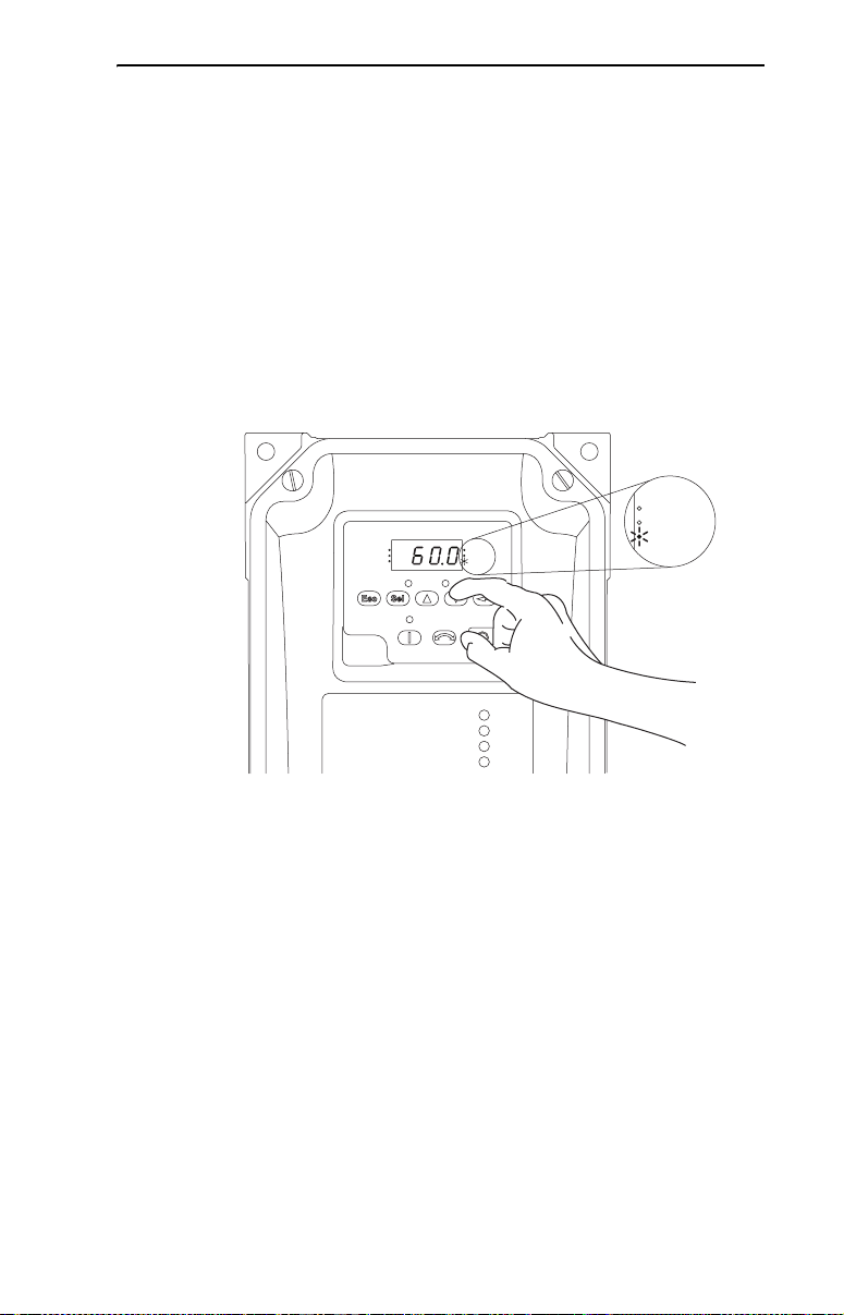
Italiano-11
Avvio, arresto, direzione e controllo velocità
I valori dei parametri predefiniti in fabbrica consentono di controllare
l’inverter dal tastierino. Non occorre alcuna programmazione per
avviare, arrestare, cambiare direzione e controllare la velocità
direttamente dal tastierino integrato.
Importante: Per disattivare il funzionamento in inversione, vedere il
parametro A095 [Disab inversione].
Modifica del riferimento della velocità di un inverter IP66, NEMA/UL
Type 4X
Quando viene visualizzato un parametro del gruppo Visualizzazione, ad
esempio d001 [Freq uscita] e il parametro P038 [Speed Ref] è impostato
su A069 [Freq interna], è possibile modificare la frequenza interna
utilizzando i tasti di direzione freccia su e freccia giù.
VOLTS
AMPS
RUN
FWD
REV
PROGRAM
VOLTS
AMPS
HERTZ
FAULT
Durante la regolazione della frequenza interna, viene visualizzato il
valore relativo e il LED Hertz lampeggia. Tutte le modifiche vengono
immediatamente salvate. Il display ritorna, quindi, al parametro del
gruppo Visualizzazione mostrato precedentemente.
HERTZ
CONSIGLIO: Per default, il riferimento della velocità di un inverter
IP66, NEMA/UL Type 4X è impostato sulla frequenza interna, A069
[Freq interna].
CONSIGLIO: È anche possibile variare il riferimento della velocità
modificando il parametro A069 [Freq interna] nella modalità
Programmazione. Per ulteriori informazioni sulla modalità
Programmazione, vedere la sezione “Visualizzazione e modifica dei
parametri”.
Il valore predefinito di A069 [Freq interna] è 0 Hz. Per gli inverter
PowerFlex 40 IP20, il valore predefinito di questo parametro è pari a
60 Hz.
Page 82

Italiano-12
Tastierino integrato
➏
➍
➋
PROGRAM
➎
➊
RUN
FWD
REV
FAULT
➌
VOLTS
AMPS
HERTZ
➐
Menu Descrizione
➑
➒
N. LED Stato spia LED Descrizione
Stato marcia/
➊
direzione
Display
➋
alfanumerico
Unità visualizzate Rossa sempre
➌
Stato programma Rossa sempre
➍
Stato guasto Rosso
➎
Stato potenziometro Verde sempre
➏
Stato tasto di avvio Verde sempre
➐
N. Tasto Nome Descrizione
➑
➒
Rossa sempre
accesa
Rosso
lampeggiante
Rossa sempre
accesa
Rosso
lampeggiante
accesa
accesa
lampeggiante
accesa
accesa
Escape Indietro di un livello nel menu di programmazione.
Selezione Avanti di un livello nel menu di programmazione.
Freccia su
Freccia giù
Invio Avanti di un livello nel menu di programmazione.
Pote nziom etro
Indica che l’inverter è in funzione, con direzione di marcia comandata.
L’inverter ha ricevuto il comando di cambiare direzione di marcia.
Indica la direzione effettiva del motore, decelerando per arrivare a
zero.
Indica il numero di parametro, il valore del parametro o il codice di
guasto.
Una cifra singola lampeggiante indica che può essere cambiata.
Tutte le cifre lampeggianti indicano una condizione di guasto.
Indica le unità del valore del parametro visualizzato.
Indica che il valore del parametro può essere cambiato.
Indica un guasto all’inverter.
Indica che il potenziometro sul tastierino integrato è attivo.
Indica che il tasto di avvio sul tastierino integrato è attivo.
Anche il tasto di inversione è attivo, a meno che non sia disabilitato
dal parametro A095 [Disab inversione].
Annulla la modifica apportata ad un valore del parametro e consente
di uscire dalla modalità Programmazione.
Seleziona una cifra durante la visualizzazione del valore del
parametro.
Per scorrere i gruppi e i parametri.
Aumenta/riduce il valore di una cifra lampeggiante.
Utilizzati per regolare la frequenza interna degli inverter IP66, NEMA/
UL Type 4X solo quando viene visualizzato un parametro del gruppo
Visualizzazione e il parametro P038 [Rif velocità] è impostato sulla
frequenza interna, A069 [Freq interna].
Salva la modifica apportata ad un valore del parametro.
(1)
Usato per controllare la velocità dell’inverter. Attivo per default.
Controllato dal parametro P038 [Rif velocità].
Gruppo Visualizzazione (solo visualizzazione)
Include condizioni operative dell’inverter
visualizzate comunemente.
Gruppo Programmazione di base
Include le funzioni programmabili usate con
maggiore frequenza.
Gruppo Programmazione avanzata
Include le restanti funzioni programmabili.
Indicatore di guasto
Include un elenco di codici pe r condizioni di guasto
specifiche. Visualizzato solo in caso di guasto.
(1)
Avvio Usato per avviare l’inverter. Attivo per default.
Indietro Usato per invertire la marcia dell’inverter. Attivo per default.
Arresto Usato per arrestare l’inverter o azzerare un guasto.
(1)
Gli inverter IP66, NEMA/UL Type 4X non sono dotati di potenziometro.
Controllato dal parametro P036 [Fonte Avvio].
Controllato dai parametri P036 [Fonte Avvio] e A095 [Disab
inversione].
Questo tasto è sempre attivo.
Controllato dal parametro P037 [Modo Arresto].
Page 83

Per ulteriori informazioni sui parametri, consultare il manuale dell’utente di PowerFlex 40.
Italiano-13
Visualizzazione e modifica dei parametri
L’ultimo parametro del gruppo Visualizzazione selezionato dall’utente viene salvato prima di togliere l’alimentazione e
visualizzato per default all’accensione.
Di seguito viene fornito un esempio delle principali funzioni del tastierino integrato e del display. Questo esempio
contiene istruzioni di base per la navigazione ed illustra come programmare il primo parametro del gruppo
Programmazione.
Passo Tasti Esempi di display
1. All’accensione, il numero dell’ultimo parametro del
gruppo Visualizzazione selezionato dall’utente viene
visualizzato brevemente con caratteri lampeggianti. Il
display passa quindi automaticamente al valore
corrente del parametro (gli esempi riportano un valore
d001 [Freq uscita] con l’inverter fermo).
2. Premere Esc una volta per visualizzare il numero del
parametro del gruppo Visualizzazione mostrato
all’accensione. Il numero del parametro lampeggia.
3. Premere nuovamente Esc per passare al menu dei
gruppi. La lettera del menu lampeggia.
4. Premere la freccia su o giù per scorrere il menu dei
gruppi (d, P e A).
5. Premere Invio o Sel per passare ad un gruppo. La cifra
a destra dell’ultimo parametro visualizzato in quel
gruppo lampeggia.
6. Premere le frecce su o giù per scorrere i parametri
contenuti nel gruppo.
7. Premere Invio o Sel per visualizzare il valore di un
parametro. Se non si intende modificare il valore,
premere Esc per tornare al numero di parametro.
8. Premere Invio o Sel per passare alla modalità
Programmazione e modificare il valore del parametro.
Se il parametro può essere modificato, la cifra a destra
lampeggia e il LED Program si accende.
9. Premere le frecce su o giù per cambiare il valore del
parametro. Se richiesto, premere Sel per spostarsi da
una cifra all’altra o da un bit all’altro. La cifra o il bit
modificabili lampeggiano.
10. Premere Esc per annullare la modifica apportata. La
cifra smette di lampeggiare, il valore precedente viene
ripristinato e il LED Program si spegne.
Oppure
Premere Invio per salvare la modifica apportata. La
cifra smette di lampeggiare e il LED Program si
spegne.
o
o
o
o
o
o
VOLTS
AMPS
HERTZ
FAULTPROGRAM
VOLTS
AMPS
HERTZ
FAULTPROGRAM
VOLTS
AMPS
HERTZ
FAULTPROGRAM
VOLTS
AMPS
HERTZ
FAULTPROGRAM
VOLTS
AMPS
HERTZ
FAULTPROGRAM
VOLTS
AMPS
HERTZ
FAULTPROGRAM
VOLTS
AMPS
HERTZ
FAULTPROGRAM
11. Premere Esc per tornare all’elenco dei parametri.
Continuare a premere Esc per uscire dal menu di
programmazione.
Se premendo Esc il display non cambia, viene
visualizzato il parametro d001 [Freq uscita]. Premere
Invio o Sel per passare al menu dei gruppi.
Il Gruppo Programmazione di base contiene i parametri modificati più frequentemente.
VOLTS
AMPS
HERTZ
FAULTPROGRAM
Page 84

Italiano-14
Per ulteriori informazioni sui parametri, consultare il manuale dell’utente di PowerFlex 40.
Parametri del gruppo Visualizzazione
N. Parametro Min/Max Display/Opzioni
d001 [Freq uscita] 0,0/[Frequenza max] 0,1 Hz
d002 [Freq comandata] 0,0/[Frequenza max] 0,1 Hz
d003 [Corr. in uscita] 0,00/(Ampere inverter × 2) 0,01 Amp
d004 [Tens. in uscita] 0/Tens nom inverter 1 V CA
d005 [Tens. bus CC] In base alla taglia dell’inverter 1 V CC
d006 [Stato unità] 0/1 (1 = Condizione vera) Bit 3
d007-d009 [Codice guasto x] F2/F122 F1
d010 [Display di proc.] 0.00/9999 0.01 – 1
d012 [Fonte controllo] 0/9 Cifra 1 = Comando velocità
d013 [Stato ingr contr] 0/1 (1 = Ingresso presente) Bit 3
d014 [Stato ingr dig] 0/1 (1 = Ingresso presente) Bit 3
d015 [Stato comun.] 0/1 (1 = Condizione vera) Bit 3
d016 [Vers softw contr] 1.00/99.99 0.01
d017 [Tipo inverter] 1001/9999 1
d018 [Tempo avvio scad] 0/9999 ore 1 = 10 ore
d019 [Dati testpoint] 0/FFFF 1 esad
d020 [Ingr anlg 0-10 V] 0,0/100,0% 0,1%
d021 [Ingr an 4-20 mA] 0,0/100,0% 0,1%
d022 [Potenza Uscita] 0,00/(Potenza inverter × 2) 0,01 kW
d023 [Fatt pot uscita] 0,0/180,0 ° 0,1 °
d024 [Temp inverter] 0/120 °C 1 °C
d025 [Stato conteggio] 0/9999 1
d026 [Stato timer] 0,0/9999 sec 0,1 sec
d028 [Stato logica stp] 0/7 1
d029 [Corr. di coppia] 0,00/(Ampere inverter × 2) 0,01 Amp
In decel. In accel. Avanti In marcia
(vedere P038; 9 = “Freq jog”) (vedere P036; 9 = “Jog”)
TransDBacc Ingr arr Dir/Indiet Avvio/Avanti
Ingr digit 4 Ingr digit 3 Ingr digit 2 Ingr digit 1
Errore DSI Tx Rx
Bit 2 Bit 1 Bit 0
Bit 2 Bit 1 Bit 0
Bit 2 Bit 1 Bit 0
Bit 2 Bit 1 Bit 0
Cifra 0 = Comando di avvio
Avviamento facilitato con i parametri di base del gruppo
Programmazione
L’inverter PowerFlex 40 è concepito per un avviamento semplice ed efficiente. Il gruppo Programmazione contiene i
parametri usati con maggiore frequenza.
= Prima di cambiare questo parametro, arrestare l’inverter.
N. Parametro Min/Max Display/Opzioni Valore predefinito
P031 [Tens Targa mot.] 20/Tens nom inverter 1 V CA In base alla taglia dell’inverter
Impostare sulla tensione nominale riportata sulla targhetta
dati del motore.
P032 [Freq. nom. mot.] 15/400 Hz 1 Hz 60 Hz
Impostare sulla frequenza nominale riportata sulla targhetta
dati del motore.
P033 [C orr sovracc mot] 0,0/ (ampere nominali
Impostato sulla corrente motore massima consentita.
P034 [Freq minima] 0,0/400,0 Hz 0,1 Hz 0,0 Hz
Imposta il livello minimo di frequenza generato di continuo
dall’inverter.
P035 [Frequenza max] 0/400 Hz 1 Hz 60 Hz
Imposta il livello massimo di frequenza generato
dall’inverter.
P036 [Fonte Avvio] 0/6 0 = “Tastierino”
Imposta lo schema di controllo usato per avviare l’inverter.
(1)
Se attivo, anche il tasto di inversione è attivo, a meno che
non sia disabilitato dal parametro A095 [Disab
inversione].
inverter× 2)
0,1 Amp In base alla taglia dell’inverter
(1)
1 = “A 3 fili”
2 = “A 2 fili”
3 = “SensLiv 2fil”
4 = “Vel al 2 fil”
5 = “Porta com.”
6 = “Av/Ind temp.”
0
Page 85

Per ulteriori informazioni sui parametri, consultare il manuale dell’utente di PowerFlex 40.
Italiano-15
= Prima di cambiare questo parametro, arrestare l’inverter.
N. Parametro Min/Max Display/Opzioni Valore predefinito
P037 [Modo Arresto] 0/9 0 = “Rampa, CF”
Attivare il modo Arresto per tutte le fonti di arresto [ad
esempio, tastierino, marcia avanti (morsetto I/O 02), indietro
(morsetto I/O 03), porta RS485] ad eccezione di quanto
annotato di seguito.
Importante: il morsetto 01 è sempre impostato sull’arresto
per inerzia, ad eccezione di quando il parametro P036
[Fonte Avvio] è impostato sul controllo “A 3 fili”. Nel controllo
a tre fili, il morsetto 01 è controllato dal parametro P037
[Modo Arresto].
P038 [R if velocità] 0/7 0 = “Pot inverter”
Imposta la sorgente del riferimento della velocità per
l’inverter.
Importante: quando il parametro [Sel ingr digit x] A051 o
A052 è impostato sull’opzione 2, 4, 5, 6, 13 o 14 e l’ingresso
digitale è attivo, A051, A052, A053 o A054 sovrascrivono il
riferimento della velocità comandato da questo parametro.
Consultare il Capitolo 1 del Manuale dell’utente di
PowerFlex 40 per ulteriori informazioni.
1 = “Inerzia, CF”
2 = “Freno CC, CF”
3 = “FrenAutCC, CF”
4 = “Rampa”
5 = “Inerzia”
6 = “Freno CC”
7 = “Freno Aut CC”
8 = “Ramp+CtrFrEM”
9 = “Rampa+FrenEM”
(1)
1 = “Freq interna”
2 = “Ingr 0-10 V”
3 = “Ingr 4-20mA”
4 = “Freq prestab”
5 = “Porta com.”
6 = “Logica arr”
7 = “MoltIngAnal”
(1)
(1)
(1)
(1)
L’ingresso di arresto azzera anche il guasto
attivo.
0
0
1 (IP66, tipo 4X)
P039 [Tempo accel. 1] 0,0/600,0 sec 0,1 sec 10,0 sec
Imposta la velocità di accelerazione per tutti gli incrementi di
velocità.
P040 [Tempo decel. 1] 0,1/600,0 sec 0,1 sec 10,0 sec
Imposta la velocità di decelerazione per tutti i decrementi di
velocità.
P041 [R eset a default] 0/1 0 = “Pronto/Fermo”
Ripristina tutti i parametri sui valori predefiniti di fabbrica.
P042 [C ateg tensione] 2/3
Imposta la classe di tensione per gli inverter da 600 V.
P043 [Tratt sovracc mot] 0/1 0 = “Disabilitato”
1 = “Rip val fabb”
2 = “Bassa tens” (480 V)
3 = “Alta tens” (600 V)
1 = “Abilitato”
0
3
0
Abilita/disabilita la funzione di ritenzione del sovraccarico motore.
Page 86

Italiano-16
Per ulteriori informazioni sui parametri, consultare il manuale dell’utente di PowerFlex 40.
Parametri del gruppo Avanzato
N. Parametro Min/Max Display/Opzioni
[Sel ingr digit 1]
A051
Morsetto I/O 05
[Sel ingr digit 2]
A052
Morsetto I/O 06
[Sel ingr digit 3]
A053
Morsetto I/O 07
[Sel ingr digit 4]
A054
Morsetto I/O 08
(1)
Importante: la fonte della velocità per gli
inverter IP66, NEMA/UL Type 4X deriva dal
parametro A069 [Freq interna].
A055 [Sel. uscita relè] 0/24 0 = “Pronto/Fermo”
A056 [Liv. uscita relè] 0.0/9999 0.1 0.0
A058
[Sel usc ottica 1]
A061
[Sel usc ottica 2]
A059
[Liv usc ottica 1]
A062
[Liv usc ottica 2]
Impostazioni A055, A058 e
A061
6 0/400 Hz
7 0/180%
8 0/815 Volt
10 0/100%
16 0,1/9999 sec
17 1/9999 imp.
18 1/180 °
20 0/1
23 0/400 Hz
A064 [Log usc ottica] 0/3 1 0
Opzione A064 Log usc ottica 1 Log uscita ottica 2
0 NA (nor malmente aperto) NA (normalmente aperto)
1 NC (nor malmente chiuso) NA (normalmente aperto)
2 NA (nor malmente aperto) NC (normalmente chiuso)
3 NC (nor malmente chiuso) NC (normalmente chiuso)
0/27 0 = “Non usato”
0/24 Vedere A055 per le
1 = “Acc e dec 2”
2 = “Jog”
3 = “Errore aus”
4 = “Freq prestab”
(1)
5 = “Locale”
6 = “Porta com”
7 = “Azzera err.”
8 = “ArrRampa, CF”
9 = “ArrInerz, CF”
10 = “ArrInCC, CF”
11 = “Jog avanti”
12 = “Jog indietro”
13 = “ContrIng 10 V”
1 = “A frequenza”
2 = “Mot in marc”
3 = “Indietro”
4 = “Sovrac mot”
5 = “Reg rampa”
6 = “Oltre freq”
7 = “Oltre corr”
8 = “Oltre VoltCC”
9 = “Ripr scadute”
10 = “Oltre V anal”
11 = “Ingr log 1”
12 = “Ingr log 2”
opzioni.
14 = “ContrIng20mA”
15 = “Disabil. PID”
16 = “MOP su”
17 = “MOP giù”
18 = “Avvio timer”
19 = “Ingr. contat.”
20 = “Reset timer”
21 = “Reset contat”
22 = “Res tim&cont”
23 = “Ingr log 1”
24 = “Ingr log 2”
25 = “Lim corr 2”
26 = “Inv analog”
27 = “Ril freno EM”
13 = “Logica 1 e 2”
14 = “Logica 1 o 2”
15 = “Usc log arr”
16 = “Usc timer”
17 = “Usc contat”
18 = “Oltre ang PF”
19 = “Perd ingAnal”
20 = “Contr param”
21 = “GuastNonRec”
22 = “ContrFrenoEM”
23 = “Oltre Fcmd”
24 = “Contr Messag” (Per
FRN 6.01 e seguenti)
0.0/9999 0.1 0.0
Valori A056, A059 e A062
min/max
Valore
predefinito
4
4
5
11
0
2
1
Page 87

Per ulteriori informazioni sui parametri, consultare il manuale dell’utente di PowerFlex 40.
Italiano-17
N. Parametro Min/Max Display/Opzioni
Valore
predefinito
A065 [Sel. uscita anlg] 0/23 1 0
Opzione Gamma uscita
0 “FreqUsc 0-10” 0-10 V 0 V = 0 Hz P035 [Frequenza max] 0-10 V
1 “CorrUsc 0-10” 0-10 V 0 V = 0 ampere 200% FLA nominale inverter 0-10 V
2 “VoltUsc 0-10” 0-10 V 0 V = 0 Volt 120% volt uscita nominale inverter 0-10 V
3 “PotUsc 0-10” 0-10 V 0 V = 0 kW 200% potenza nominale inverter 0-10 V
4 “DatiPr 0-10” 0-10 V 0 V = 0000 65535 (FFFF esadecimali) 0-10 V
5 “FreqUsc 0-20” 0-20 mA 0 mA = 0 Hz P035 [Frequenza max] 0-20 mA
6 “CorrUsc 0-20” 0-20 mA 0 mA = 0 ampere 200% FLA nominale inverter 0-20 mA
7 “VoltUsc 0-20” 0-20 mA 0 mA = 0 Volt 120% volt uscita nominale inverter 0-20 mA
8 “PotUsc 0-20” 0-20 mA 0 mA = 0 kW 200% potenza nominale inverter 0-20 mA
9 “DatiPr 0-20” 0-20 mA 0 mA = 0000 65535 (FFFF esadecimali) 0-20 mA
10 “FreqUsc 4-20” 4-20 mA 4 mA = 0 Hz P035 [Frequenza max] 0-20 mA
11 “CorrUsc 4-20” 4-20 mA 4 mA = 0 ampere 200% FLA nominale inverter 0-20 mA
12 “VoltUsc 4-20” 4-20 mA 4 mA = 0 Volt 120% volt uscita nominale inverter 0-20 mA
13 “PotUsc 4-20” 4-20 mA 4 mA = 0 kW 200% potenza nominale inverter 0-20 mA
14 “DatiPr 4-20” 4-20 mA 4 mA = 0000 65535 (FFFF esadecimali) 0-20 mA
15 “CoppUsc 0-10” 0-10 V 0 V = 0 ampere 200% FLA nominale inverter 0-10 V
16 “CoppUsc 0-20” 0-20 mA 0 mA = 0 ampere 200% FLA nominale inverter 0-20 mA
17 “CoppUsc 4-20” 4-20 mA 4 mA = 0 ampere 200% FLA nominale inverter 0-20 mA
18 “Prest 0-10” 0-10 V 0 V = 0% 100,0% impostazione setpoint 0-10 V
19 “Prest 0-20” 0-20 mA 0 mA = 0% 100,0% impostazione setpoint 0-20 mA
20 “Prest 4-20” 4-20 mA 4 mA = 0% 100,0% impostazione setpoint 0-20 mA
21 “FreqMin 0-10” 0-10 V 0V = freq min. P035 [Frequenza max] 0-10 V
22 “FreqMin 0-20” 0-20 mA 0 mA = freq min. P035 [Frequenza max] 0-20 mA
23 “FreqMin 4-20” 4-20 mA 4 mA = freq min. P035 [Frequenza max] 0-20 mA
Valore di uscita
minimo
Valore di uscita massimo
[Uscita anlg alta]
Posizione
microinterruttore
A066 [Uscita anlg alta] 0/800% 1% 100%
A067 [Tempo accel. 2] 0,0/600,0 sec 0,1 sec 20,0 sec
A068 [Tempo decel. 2] 0,1/600,0 sec 0,1 sec 20,0 sec
A069 [Freq interna] 0,0/400,0 Hz 0,1 Hz 0,0 Hz (per gli
[Freq. predef. 0]
A070
A071
[Freq. predef. 1]
A072
[Freq. predef. 2]
A073
[Freq. predef. 3]
A074
[Freq. predef. 4]
A075
[Freq. predef. 5]
A076
[Freq. predef. 6]
A077
[Freq. predef. 7]
(1)
Per attivare [Freq predef 0] impostare il parametro P038 [Rif velocità] sull’opzione 4.
Stato ingresso
(morsetto I/O 05)
(2)
(1)
0,0/400,0 Hz 0,1 Hz 0,0 Hz
di ingr dig 1
Quando un ingresso digitale viene impostato su “Accel. 2 e decel. 2” e l’ingresso è attivo, quell’ingresso sovrascrive le
impostazioni contenute in questa tabella.
Stato ingresso
di ingr dig 2
(morsetto I/O 06)
0 0 0 [Freq. predef. 0] [Tempo accel. 1] / [Tempo decel. 1]
1 0 0 [Freq. predef. 1] [Tempo accel. 1] / [Tempo decel. 1]
0 1 0 [Freq. predef. 2] [Tempo accel. 2] / [Tempo decel. 2]
1 1 0 [Freq. predef. 3] [Tempo accel. 2] / [Tempo decel. 2]
0 0 1 [Freq. predef. 4] [Tempo accel. 1] / [Tempo decel. 1]
1 0 1 [Freq. predef. 5] [Tempo accel. 1] / [Tempo decel. 1]
0 1 1 [Freq. predef. 6] [Tempo accel. 2] / [Tempo decel. 2]
1 1 1 [Freq. predef. 7] [Tempo accel. 2] / [Tempo decel. 2]
Stato ingresso
di ingr dig 3
(morsetto I/O 07)
Sorgente della
frequenza
Parame tro
di accelerazione/
decelerazione usato
(2)
inverter IP66,
NEMA/UL
Type 4X)
60,0 Hz (per
inverter IP20)
5,0 Hz
10,0 Hz
20,0 Hz
30,0 Hz
40,0 Hz
50,0 Hz
60,0 Hz
A078 [Frequenza jog] 0,0/ [Frequenza max] 0,1 Hz 10,0 Hz
A079 [Accel/decel/ jog] 0,1/600,0 sec 0,1 sec 10,0 sec
A080 [Tempo freno CC] 0,0/99,9 sec 0,1 sec 0,0 sec
Impostando 99,9 sec. = Continuo
A081 [Liv freno CC] 0,0/(Ampere inverter ×
1,8)
A082 [Sel resis freno d.] 0/99 0 = “Disabilitato”
A083 [% Curva S] 0/100% 1% 0%
0,1 Amp Ampere ×
1 = “Res RA norm”
2 = “No protez.”
3-99 = % ciclo di carico
0,05
0
(disabilitato)
Page 88

Italiano-18
Per ulteriori informazioni sui parametri, consultare il manuale dell’utente di PowerFlex 40.
N. Parametro Min/Max Display/Opzioni
A084 [Selezione boost] 0/14 Impostazioni in % della tensione di base. 8
Attivo solo quando A125 [Mod prest coppia] è
impostato su 0 “V/Hz”.
A085
[Boost in Avvio] 0,0/25,0%
Attivo solo quando A084 [Selezione boost] e A125 [Mod prest coppia] sono impostati su “0”.
A086
[Tensione interr.] 0,0/100,0%
Attivo solo quando A084 [Selezione boost] e A125 [Mod prest coppia] sono impostati su “0”.
A087
[Freq. interr.] 0,0/400,0 Hz
Attivo solo quando A084 [Selezione boost] e A125 [Mod prest coppia] sono impostati su “0”.
A088 [Tensione massima] 20/Volt nominali 1 V CA Tensione
A089 [Limite corr. 1] 0,1/(Ampere inverter ×
A090 [Sel. sovr. mot.] 0/2 0 = “No declas.” 1 = “Declas. min”
A091 [Frequenza PWM] 2,0/16,0 kHz 0,1 kHz 4,0 kHz
A092 [Tent riavvio aut] 0/9 1 0
A093 [Rit. riavvio aut] 0,0/300,0 sec 0,1 sec 1,0 sec
A094 [Avvio all’acc] 0/1 0 = “Disabilitato” 1 = “Abilitato” 0
A095 [Disab inversione] 0/1 0 = “Inv. Abilit.” 1 = “Inv. Disab.” 0
A096 [StartVolo abil.] 0/1 0 = “Disabilitato” 1 = “Abilitato” 0
A097 [Compensazione] 0/3 0 = “Disabilitato”
A098 [Scatto corr SW] 0,0/(Ampere inverter × 2) 0,1 Amp 0,0
A099 [Fattore di proc] 0.1/999.9 0.1 30.0
A100 [Azzera guasti] 0/2 0 = “Pronto/Fermo” 1 = “Reset err.”
A101 [Blocco programma] 0/9999 0 = “Sbloccato” 1 = “Bloccato” 0
A102 [Sel. testpoint] 400/FFFF 1 esad 400
A103 [Freq. dati comun.] 0/5 0 = “1200”
Per rendere effettive le modifiche apportate
occorre spegnere e riaccendere l’inverter.
A104 [Ind. nodo comun.] 1/247 1 100
Per rendere effettive le modifiche apportate
occorre spegnere e riaccendere l’inverter.
A105 [AzioneGuastiCom] 0/3 0 = “Errore”
A106 [Tempo perd com.] 0,1/60,0 sec 0,1 sec 5,0 sec
A107 [Formato comun.] 0/5 0 = “RTU 8-N-1”
Per rendere effettive le modifiche apportate
occorre spegnere e riaccendere l’inverter.
A108 [Lingua] 1/10 1 = “English”
A109 [Prest usc anal] 0,0/100,0% 0,1% 0,0%
A110 [Ing an 0-10 V ba] 0,0/100,0% 0,1% 0,0%
1,8)
0 = “V/Hz person”
Coppia variabile
1 = “30,0, VT” 5 = “0,0, no IR” 10 = “10,0, CT”
2 = “35,0, VT” 6 = “0,0” 11 = “12,5, CT”
3 = “40,0, VT” 7 = “2,5, CT” 12 = “15,0, CT”
4 = “45,0, VT” 8 = “5,0, CT” 13 = “17,5, CT”
0,1% 2,5%
0,1% 25,0%
0,1 Hz 15,0 Hz
0,1 Amp Ampere × 1,5
1 = “Elettrico”
1 = “2400”
2 = “4800”
1 = “Arr inerz”
1 = “RTU 8-E-1”
2 = “RTU 8-O-1”
2 = “Français”
3 = “Español”
4 = “Italiano”
5 = “Deutsch”
Coppia costante
9 = “7,5, CT” 14 = “20,0, CT”
2 = “Declas. max”
2 = “Meccanico”
3 = “Entrambi”
2 = “Azz. buffer”
3 = “9600”
4 = “19,2 K”
5 = “38,4 K”
2 = “Arresto”
3 = “Cont ultimo”
3 = “RTU 8-N-2”
4 = “RTU 8-E-2”
5 = “RTU 8-O-2”
6 = “Riservato”
7 = “Português”
8 = “Riservato”
9 = “Riservato”
10 = “Nederlands”
Valore
predefinito
7 4-11 kW
(5-15 HP)
nomin
0
1
(Disabilitato)
0
3
0
0
1
A111 [Ing an 0-10 V al] 0,0/100,0% 0,1% 100,0%
A112 [Ing an 4-20 mA b] 0,0/100,0% 0,1% 0,0%
Page 89

Per ulteriori informazioni sui parametri, consultare il manuale dell’utente di PowerFlex 40.
Italiano-19
N. Parametro Min/Max Display/Opzioni
A113 [Ing an 4-20 mA a] 0,0/100,0% 0,1% 100,0%
A114 [Freq scorr a FLA] 0,0/10,0 Hz 0,1 Hz 2,0 Hz
A115 [Tempo proc basso] 0.00/99.99 0.01 0.00
A116 [Tempo proc alto] 0.00/99.99 0.01 0.00
A117 [Modo reg bus] 0/1 0 = “Disabilitato” 1 = “Abilitato” 1
A118 [Limite corr. 2] 0,1/(Ampere inverter ×
A119 [Frequenza salto] 0/400 Hz 1 Hz 0 Hz
A120 [Banda freq. salto] 0,0/30,0 Hz 0,1 Hz 0,0 Hz
A121 [Tempo mot stallo] 0/5 0 = “60 secondi
A122 [Perd ingr anal.] 0/6 0 = “Disabilitato”
A123 [Abil. bipol 10 V] 0/1 0 = “Ingr unipol” 1 = “Ing bipolare” 0
A124 [Disab PWM variab] 0/1 0 = “Abilitato” 1 = “Disabilitato” 0
A125 [Mod prest coppia] 0/1 0 = “V/Hz” 1 = “Vett sensore” 1
A126 [FLA nom. mot.] 0,1/(Ampere inverter × 2) 0,1 Amp Amp nom.
A127 [Autotune] 0/2 0 = “Pronto/Fermo”
A128 [Cad tensione IR] 0,0/230,0 V CA 0,1 V CA Tensione
A129 [Rif corr. fluss] 0,00/[FLA nom. mot.] 0,01 Amp Amp nom.
A130 [Trim PID alto] 0.0/400.0 0.1 60.0
A131 [Trim PID basso] 0.0/400.0 0.1 0.0
A132 [Sel rif. PID] 0/8 0 = “PID disabil.”
A133 [Sel feedback PID] 0/2 0 = “Ingr 0-10 V”
A134 [Guad prop PID] 0.00/99.99 0.01 0.01
A135 [Tempo integr PID] 0,0/999,9 sec 0,1 sec 0,1 sec
A136 [Tasso diff PID] 0,00/99,99 (1/sec) 0,01 (1/sec) 0,01 (1/sec)
A137 [PID prestab.] 0,0/100,0% 0,1% 0,0%
A138 [PID banda morta] 0,0/10,0% 0,1% 0,0%
A139 [PID precarico] 0,0/400,0 Hz 0,1 Hz 0,0 Hz
A140-
[Stp Logic 0-7] 0001/bAFF 4 cifre
A147
A150-
[Stp Logic Time 0-7] 0,0/999,9 sec 0,1 sec 30,0 sec
A157
A160 [RitFrMeccDisatt] 0,01/10,00 sec 0,01 sec 2,00 sec
A161 [RitFrenoMeccAtt] 0,01/10,00 sec 0,01 sec 2,00 sec
A162 [Sel reset MOP] 0/1 0 = “Rif MOP zero” 1 = “SalvaRif MOP” 1
A163 [Lim freno dinam] 0,0/110,0% 0,0% 100,0%
A164 [Mod scritt com] 0/1 0 = “Salva” 1 = “Solo RAM” 0
A165 [Ritardo perd. anal.] 0,0/20,0 sec 0,1 sec 0,0 sec
A166 [Filtro ing anal] 0/14 1 0
A167 [ErroreInversPID] 0/1 0 = “Non invertito” 1 = “Invertito” 0
1,8)
0,1 Amp Ampere × 1,5
1 = “120 secondi
2 = “240 secondi
1 = “Errore (F29)”
2 = “Arresto”
3 = “Rif zero”
1 = “Sint statica”
1 = “PID prestab.”
2 = “Ingr 0-10 V”
3 = “Ingr 4-20mA”
4 = “Porta com”
1 = “Ingr 4-20mA”
Per un elenco delle opzioni per le cifre, consultare il
Manuale dell’utente di PowerFlex 40.
3 = “360 secondi
4 = “480 secondi
5 = “Err disab.”
4 = “Ref freq min”
5 = “Rif freq max”
6 = “Rif freq int”
2 = “Rotaz sint” 0
5 = “Trim prestab”
6 = “0-10 V, Trim”
7 = “4-20 mA. Trim”
8 = “Comun., Trim”
2 = “Porta com” 0
Valore
predefinito
0
0
nomin
0
00F1
Page 90

Italiano-20
Codici di errore
Per azzerare un guasto, premere il tasto Arresto, spegnere e riaccendere o
impostare il parametro A100 [Azzera guasti] su 1 o 2.
N. Errore Descrizione
F2 Ingresso ausil.
F3 Ondulazione tensione
del bus CC eccessiva
F4 Sottotensione
F5 Sovratensione
F6 Motore in stallo
F7 Sovracc. motore
F8 Sovrat. dissip.
F12 Sovrac. hardware Controllare la programmazione. Controllare un eventuale carico eccessivo, un’impostazione di
F13 Guasto terra Controllare il cablaggio motore ed esterno ai morsetti di uscita dell’inverter per la messa a terra.
F29 Perd ingr anal.
F33 Tent riavvio aut Correggere la causa del guasto ed azzerare manualmente.
F38 Da faseU a terra Controllare il cablaggio tra l’inverter e il motore. Controllare il motore per rilevare una fase a
F39 Da faseV a terra
F40 Da faseW a terra
F41 Cortoc fase UV Controllare il cablaggio motore e dei morsetti di uscita dell’inverter per rilevare un cortocircuito.
F42 Cortoc fase UW
F43 Cortoc fase VW
F48 Param a default L’inverter ha ricevuto il comando di scrivere i valori predefiniti sulla EEPROM. Azzerare il guasto
F63 Sovrac. SW
F64 Sovracc inverter Ridurre il carico o aumentare il tempo di accelerazione.
F70 Unità di pot Spegnere e riaccendere. Sostituire l’inverter qualora non fosse possibile eliminare il guasto.
F71 Perd rete adat La rete di comunicazione non funziona.
F80 Autotune SVC La funzione autotune è stata annullata dall’utente o non è riuscita.
F81 Perdita comunic Se la scheda non è stata scollegata intenzionalmente, controllare il cablaggio alla porta.
F100 Checksum param. Ripristinare i valori predefiniti.
F122 Guast scheda I/O Spegnere e riaccendere. Sostituire l’inverter qualora non fosse possibile eliminare il guasto.
(1)
Errore di auto-reset/run. Configurare con i parametri A092 e A093.
(1)
Controllare il cablaggio remoto.
Monitorare la linea di ingresso per eventuale mancanza di fase o squilibrio della linea. Quindi,
controllare il fusibile della linea di ingresso.
(1)
Monitorare la linea in CA in entrata per rilevare una bassa tensione o un’interruzione alla linea
stessa.
(1)
Monitorare la linea CA per rilevare condizioni di alta tensione di linea o transitori. La
sovratensione bus può essere causata anche dalla rigenerazione del motore. Estendere il
tempo di decelerazione o installare l’opzione di frenatura dinamica.
(1)
Aumentare [Tempo accel. x] o ridurre il carico in modo che la corrente in uscita dell’inverter non
superi il valore impostato dal parametro A089 [Limite corr.].
(1)
Condizione di carico motore eccessivo. Ridurre il carico in modo che la corrente in uscita
dell’inverter non superi la corrente impostata dal parametro P033 [Corr sovracc mot].
(1)
Controllare che le alette del dissipatore di calore non siano ostruite o sporche. Controllare
che la temperatura ambiente non abbia superato i 40 ° C (104 °F) per configurazioni IP 3 0/NEMA 1/
UL Type 1 o 50 °C (122 °F) per configurazioni di tipo aper to.
Controllare la ventola.
boost CC non corretta, tensioni di frenatura CC troppo alte o altre cause.
(1)
Un ingresso analogico è configurato per un guasto alla perdita del segnale. Si è verificata una
perdita del segnale.
massa.
Sostituire l’inverter qualora non fosse possibile eliminare il guasto.
Sostituire l’inverter qualora non fosse possibile eliminare il guasto.
o spegnere e riaccendere l’inverter. Programmare i parametri dell’inverter secondo necessità.
(1)
Controllare i requisiti di carico e l’impostazione del parametro A098 [SW Current Trip].
Sostituire il cablaggio, l’espansione por ta, le schede o completare l’inverter secondo necessità.
Controllare il collegamento. Una scheda è stata scollegata intenzionalmente. Spegnere usando
A105 [AzioneGuastiCom].
Page 91

Dimensioni dell’inverter
Tipi di frame del PowerFlex 40 – I valori sono in kW e (HP)
120 V CA –
Frame
Monofase
B 0,4 (0,5)
0,75 (1,0)
1,1 (1,5)
(1)
C
(1)
Gli inverter IP66, NEMA/UL Type 4X non sono disponibili nel frame C.
IP20, NEMA/UL tipo aperto
A
D
240 V CA –
Monofase 240 V CA – Trifase 480 V CA – Trifase 600 V CA – Trifase
0,4 (0,5)
0,75 (1,0)
1,5 (2,0)
2,2 (3,0) 5,5 (7,5)
C
0,4 (0,5)
0,75 (1,0)
1,5 (2,0)
7,5 (10,0)
Le dimensioni sono espresse in millimetri e (pollici).
I pesi sono espressi in chilogrammi e (libbre).
2,2 (3,0)
3,7 (5,0)
0,4 (0,5)
0,75 (1,0)
1,5 (2,0)
5,5 (7,5)
7,5 (10,0)
2,2 (3,0)
0,75 (1,0)
4,0 (5,0)
1,5 (2,0)
2,2 (3,0)
11,0 (15,0) 5,5 (7,5)
7,5 (10,0)
Italiano-21
4,0 (5,0)
11,0 (15,0)
E
B
5.5 (0.22)
Kit opzionali per comunicazioni, filtro RFI, IP 30/NEMA 1/UL Type 1
B
A
C
D
Inverter
Opzione
Dimensioni
A Copertura per
adattatori di
comunicazione
B Filtro di linea EMC 50 (1,97) 60 (2,36)
C Filtro di linea EMC 229 (9,02) 309 (12,17)
D IP30/NEMA 1/UL
Typ e 1
IP30/NEMA 1/UL
Type 1 per la
copertura per
adattatori di
comunicazione
Inverter
frame B
frame C
25 (0,98) 25 (0,98)
33 (1,30) 60 (2,36)
64 (2,52) 60 (2,36)
F
ABCDEF
Frame
B100
(3,94)
C130
(5,1)
79.1 (3.11)
64.1 (2.52)
40.6 (1.60)
25.6 (1.01)
Frame B – 22-JBAB
77.5 (3.05)
50.0 (1.97)
22.5 (0.89)
Frame B – 22-JBCB
(usato con la copertura per
adattatori di comunicazione)
180
136
(7,09)
(5,35)87(3,43)
260
180
(10,2)
(7,1)
∅
22.2
(0.87)
109.9
(4.33)
74.3
(2.93)
∅
22.2
(0.87)
134.3
(5.29)
105.3
(4.15)
76.3
(3.00)
(usato con la copertura per
adattatori di comunicazione)
168
87.4
(6,61)
246
(9,7)
(3,44)
–4.3
116
(4,57)
107.0 (4.21)
66.0 (2.60)
24.0 (0.94)
Frame C – 22-JBAC
108.7 (4.28)
92.2 (3.63)
69.2 (2.72)
45.7 (1.80)
22.2 (0.87)
Frame C – 22-JBCC
Peso
alla
spedizi
one
2.2
(4,9)
(9,5)
∅
111.2
(4.38)
∅
144.8
(5.70)
109.8
(4.32)
28.5
(1.12)
∅
152.2
(5.99)
28.5
(1.12)
∅
22.2
(0.87)
22.2
(0.87)
179.8
(7.08)
Page 92

Italiano-22
IP66, NEMA Type/UL Type 4X – Le dimensioni sono espresse in millimetri e (pollici) I pesi
sono espressi in chilogrammi e (libbre).
165
(6.50)
Peso
5,2 (11,5)
146
(5.75)
253
(9.96)
270
(10.63)
6.5
(0.26)
28
(1.10)
22
(0.87)
46
(1.81)
23
(0.91)
82.5
(3.25)
89
(3.50)
124
(4.88)
198
(7.80)
Pubblicazione 22B-QS001F-IT-P – Dicembre 2008
Sostituisce la pubblicazione di maggio 2008 Copyright © 2008 Rockwell Automation, Inc. Tutti i diritti riservati.
Page 93

Inicio rápido
Variador de CA de frecuencia
ajustable PowerFlex 40
FRN 5.xx - 6.xx
Esta Guía de inicio rápido resume los pasos básicos necesarios para instalar,
poner en marcha y programar el variador de CA de frecuencia ajustable
PowerFlex 40.
del usuario y está dirigida sólo al personal calificado encargado de
realizar el mantenimiento del variador.
Para obtener información detallada sobre el PowerFlex 40, incluidas las
instrucciones sobre compatibilidad electromagnética, consideraciones de
aplicación y medidas de precaución relacionadas, consulte el documento
PowerFlex 40 User Manual, Publicación 22B-UM001… en
www.rockwellautomation.com/literature.
Precauciones generales
ATENCIÓN: El variador contiene condensadores de alto voltaje, los
cuales demoran algún tiempo en descargarse después de desconectarse el
suministro eléctrico. Antes de trabajar en el variador, asegúrese de que la
!
alimentación principal se ha desconectado de las entradas de línea [R, S, T
(L1, L2, L3)]. Espere tres minutos para que se descarguen los
condensadores hasta niveles de voltaje inocuos. El no observar estas
indicaciones puede resultar en lesiones personales o la muerte.
Los indicadores LED apagados no constituyen una indicación de que los
condensadores se hayan descargado hasta niveles de voltaje inocuos.
ATENCIÓN: Existe el riesgo de daño al equipo y/o lesiones personales si
el parámetro A092 [Auto Rstrt Tries] o A094 [Start At PowerUp] se utilizan
en una aplicación inapropiada. No utilice esta función sin considerar los
!
reglamentos, estándares y códigos locales, nacionales e internacionales, así
como las pautas de la industria.
ATENCIÓN: Sólo el personal calificado y familiarizado con los
variadores de frecuencia ajustable de CA y las maquinarias asociadas debe
planificar o realizar la instalación, la puesta en marcha y el mantenimiento
!
del sistema. El incumplimiento de estas indicaciones puede resultar en
lesiones personales y/o daño al equipo.
ATENCIÓN: Este variador tiene componentes y ensamblajes sensibles a
las descargas electrostáticas (ESD). Se deben tomar precauciones para el
control de la electricidad estática al instalar, probar, realizar mantenimiento
!
o reparar este ensamble. El no seguir los procedimientos de control de ESD
puede resultar en daño a los componentes. Si no está familiarizado con los
procedimientos de control de estática, consulte la publicación 8000-4.5.2 de
Allen-Bradley, “Guarding Against Electrostatic Damage” o cualquier otro
manual de protección contra descargas electrostáticas.
ATENCIÓN: La instalación o aplicación incorrecta de un variador puede
dañar los componentes o acortar la vida útil del producto. Los errores de
cableado o de aplicación, tales como un tamaño insuficiente del motor,
!
fuente de alimentación de CA incorrecta o inadecuada, o temperaturas
ambiente excesivas, pueden resultar en un funcionamiento defectuoso del
sistema.
La información proporcionada no reemplaza el manual
Page 94

Español-2
Consideraciones para el montaje
• Instale el variador en posición vertical sobre una superficie vertical y
nivelada.
Estructura Tamaño de
los tornillos
B M4 (#8-32) 1.56–1.96 Nm (14–17 lb-pulg.) 35 mm
C M5 (#10-24) 2.45–2.94 Nm (22–26 lb-pulg.) –
B (IP66,
Tipo 4X)
M6 (#12-24) 3.95–4.75 Nm (35–42 lb-pulg.) –
• Evite el polvo o las partículas metálicas para proteger el ventilador
de enfriamiento.
• No lo exponga a una atmósfera corrosiva.
• Proteja la unidad contra la humedad y la luz solar directa.
Espacios libres mínimos de montaje
La página 21 contiene información sobre las dimensiones de montaje.
Par de apriete de los tornillos Riel DIN
120 mm
(4.7 in.)
120 mm
(4.7 in.)
El objeto más cercano
que puede obstruir el
flujo de aire a través
del disipador térmico
y el chasis
120 mm
(4.7 in.)
Opción de montaje A
No se requiere espacio libre
120 mm
(4.7 in.)
Opción de montaje B
entre los variadores.
Temperatura ambiente de funcionamiento
Temperatura ambiente Clasificación del
Mínimo Máximo
envolvente
IP20, NEMA/UL Tipo abierto Use la opción de montaje A
–10 °C (14 °F)
40 °C (104 °F)
IP66, NEMA/UL Tipo 4X Use la opción de montaje A
IP30, NEMA/UL Tipo 1
50 °C (122 °F) IP20, NEMA/UL Tipo abierto Use la opción de montaje B
(1)
La clasificación requiere la instalación del kit opcional IP 30, NEMA/UL Tipo 1 del
PowerFlex 40P.
Espacios libres mínimos
de montaje
(1)
Use la opción de montaje B
25 mm
(1.0 in.)
Page 95

Conexión a tierra típica
Español-3
R/L1
S/L2
T/L3
SHLD
U/T1
V/T2
W/T3
Desconexión de los varistores MOV
A fin de evitar daños en el variador, los varistores MOV conectados a
tierra deben desconectarse si el variador está instalado en un sistema de
distribución sin conexión a tierra donde las tensiones entre línea y tierra
en cualquier fase puedan superar el 125 % del nivel de tensión entre una
línea y otra. Para desconectar estos dispositivos, retire el puente
mostrado en las figuras siguientes.
1. Gire el tornillo en sentido contrario a las manecillas del reloj para
aflojarlo.
2. Extraiga completamente el puente del chasis del variador.
3. Apriete el tornillo para mantenerlo en su lugar.
Ubicación del puente
IP66, NEMA/UL Tipo 4XIP20, NEMA/UL Tipo abierto
Importante: Apriete el tornillo después de retirar el puente.
Desmontaje de varistores MOV entre fase y tierra
AC Input
R/L1
S/L2
T/L3
Jumper
Three-Phase
123
4
Page 96

Español-4
Conformidad con CE
Consulte el PowerFlex 40 User Manual para obtener detalles respecto a
cómo cumplir con las directivas sobre bajo voltaje (LV) y sobre
compatibilidad electromagnética (EMC).
Especificaciones, fusibles y disyuntores
Características nominales del variador
Clasificaciones
(1)
de salida
kW (HP) Amps
Número de
catálogo
Entrada monofásica 100–120 VCA (±10 %) – Salida trifásica 0–230 V
22B-V2P3x104 0.4 (0.5) 2.3 90–132 1.15 9.0 15 140M-C2E-C16 100-C12 40
22B-V5P0x104 0.75 (1.0) 5.0 90–132 2.45 20.3 35 140M-D8E-C20 100-C23 60
22B-V6P0x104 1.1 (1.5) 6.0 90–132 3.0 24.0 40 140M-F8E-C32 100-C37 80
Entrada monofásica 200–240 VCA (±10 %)
22B-A2P3x104 0.4 (0.5) 2.3 180–264 1.15 6.0 10 140M-C2E-B63 100-C09 40
22B-A5P0x104 0.75 (1.0) 5.0 180–264 2.45 12.0 20 140M-C2E-C16 100-C12 60
22B-A8P0x104 1.5 (2.0) 8.0 180–264 4.0 18.0 30 140M-D8E-C20 100-C23 85
22B-A012x104 2.2 (3.0) 12.0 180–264 5.5 25.0 40 140M-F8E-C32 100-C37 125
Entrada trifásica 200–240 VCA (±10 %) – Salida trifásica 0–230 V
22B-B2P3x104 0.4 (0.5) 2.3 180–264 1.15 2.5 6 140M-C2E-B40 100-C07 40
22B-B5P0x104 0.75 (1.0) 5.0 180–264 2.45 5.7 10 140M-C2E-C10 100-C09 60
22B-B8P0x104 1.5 (2.0) 8.0 180–264 4.0 9.5 15 140M-C2E-C16 100-C12 85
22B-B012x104 2.2 (3.0) 12.0 180–264 5.5 15.5 25 140M-C2E-C16 100-C23 125
22B-B017x104 3.7 (5.0) 17.5 180–264 8.6 21.0 30 140M-F8E-C25 100-C23 180
22B-B024x104 5.5 (7.5) 24.0 180–264 11.8 26.1 40 140M-F8E-C32 100-C37 235
22B-B033x104 7.5 (10.0) 33.0 180–264 16.3 34.6 60 140M-G8E-C45 100-C60 305
Entrada trifásica 380–480 VCA (±10 %) – Salida trifásica 0–460 V
22B-D1P4x104 0.4 (0.5) 1.4 342–528 1.4 1.8 3 140M-C2E-B25 100-C07 35
22B-D2P3x104 0.75 (1.0) 2.3 342–528 2.3 3.2 6 140M-C2E-B40 100-C07 50
22B-D4P0x104 1.5 (2.0) 4.0 342–528 4.0 5.7 10 140M-C2E-B63 100-C09 70
22B-D6P0x104 2.2 (3.0) 6.0 342–528 5.9 7.5 15 140M-C2E-C10 100-C09 100
22B-D010x104 4.0 (5.0) 10.5 342–528 10.3 13.0 20 140M-C2E-C16 100-C23 160
22B-D012x104 5.5 (7.5) 12.0 342–528 11.8 14.2 25 140M-D8E-C20 100-C23 175
22B-D017x104 7.5 (10.0) 17.0 342–528 16.8 18.4 30 140M-D8E-C20 100-C23 210
22B-D024x104 11.0 (15.0) 24.0 342–528 23.4 26.0 50 140M-F8E-C32 100-C43 300
Entrada trifásica 460–600 VCA (±10 %) – Salida trifásica 0–575 V
22B-E1P7x104 0.75 (1.0) 1.7 414–660 2.1 2.3 6 140M-C2E-B25 100-C09 50
22B-E3P0x104 1.5 (2.0) 3.0 414–660 3.65 3.8 6 140M-C2E-B40 100-C09 70
22B-E4P2x104 2.2 (3.0) 4.2 414–660 5.2 5.3 10 140M-C2E-B63 100-C09 100
22B-E6P6x104 4.0 (5.0) 6.6 414–660 8.1 8.3 15 140M-C2E-C10 100-C09 160
22B-E9P9x104 5.5 (7.5) 9.9 414–660 12.1 11.2 20 140M-C2E-C16 100-C16 175
22B-E012x104 7.5 (10.0) 12.2 414–660 14.9 13.7 25 140M-C2E-C16 100-C23 210
22B-E019x104 11.0 (15.0) 19.0 414–660 23.1 24.1 40 140M-D8E-C25 100-C30 300
(1)
En los números de catálogo listados, “x” representa el tipo de envolvente. Las especificaciones
son válidas para todos los tipos de envolvente. Las clasificaciones IP66, NEMA/UL Tipo 4X están
disponibles sólo en variadores de estructura B.
(2)
200–240 VCA – Los variadores monofásicos también están disponibles con un filtro EMC integral.
El sufijo del catálogo cambia de N104 a N114. La opción de filtro no está disponible para los
variadores con clasificación IP66, NEMA/UL Tipo 4X.
Clasificaciones
de entrada
Rango de
voltajes kVA Amps Fusibles
(2)
– Salida trifásica 0–230 V
Protección de circuitos
de bifurcación
Protectores de
Motor 140M
Contactores
Disipación
de potencia
IP20 abierto
Watt s
Page 97

Español-5
Clasificaciones de entrada/salida
Frecuencia de salida: 0–400 Hz (programable)
Eficiencia: 97.5 % (típica)
Entradas de control digital
(corriente de entrada = 6 mA)
Modo SRC (surtidor):
18–24 V = ACTIVADO
0–6 V = DESACTIVADO
Modo SNK (drenador):
0–6 V = ACTIVADO
18–24 V =
DESACTIVADO
D
9
E
6
T
6
S
X
I
Aprobaciones
L
U
UL508C
L
®
I
N
Q
D
E
C
T
O
N
Entradas de control analógico
4–20 mA analógicas: Impedancia de entrada de 250 ohms
0–10 VCC analógicas: Impedancia de entrada de 100 k ohms
Pot. externo: 1–10 k ohms, 2 watts mínimo
D
9
E
6
T
6
S
X
I
L
U
CSA 22.2
L
C
®
I
N
Q
D
E
C
T
O
N
EMC Directive 89/336
LV: EN 50178, EN 60204
EMC: EN 61800-3, EN 50081-1, EN 50082-2
Salida de control
Salida programable (relé formato C)
Clasificación resistiva: 3.0 A a 30 VCC, 3.0 A a 125 VCA, 3.0 A a 240 VCA
Clasificación inductiva: 0.5 A a 30 VCC, 0.5 A a 125 VCA, 0 .5 A a 240 VCA
Salidas de
optoacoplador
30 VCC, 50 mA
No inductivas
Salidas analógicas (10 bit)
0–10 V, 1 k ohm mín.
4–20 mA, 525 ohm máx.
Fusibles y disyuntores
Tipo de fusible recomendado: UL Clases J, CC, T o Tipo BS88; 600 V (550 V) o equivalente.
Disyuntores recomendados: Disyuntores HMCP o equivalentes.
Funciones de protección
Protección del motor: I2t protección contra sobrecarga – 150 % durante 60 seg., 200 % durante 3 seg.
(proporciona protección Clase 10)
Sobrecorriente: 200 % límite del hardware, 300 % fallo instantáneo
Sobrevoltaje: Entrada de 100–120 VCA – El disparo ocurre a un voltaje de bus de 405 VCC (equivalente a línea de
Entrada de 200–240 VCA – El disparo ocurre a un voltaje de bus de 405 VCC (equivalente a línea de
Entrada de 380–460 VCA – El disparo ocurre a un voltaje de bus de 810 VCC (equivalente a línea de
Entrada de 460–600 VCA – El disparo ocurre a un voltaje de bus de 1005 VCC (equivalente a línea de
Bajo voltaje: Entrada de 100–120 VCA – El disparo ocurre a un voltaje de bus de 210 VCC (equivalente a línea de
Entrada de 200–240 VCA – El disparo ocurre a un voltaje de bus de 210 VCC (equivalente a línea de
Entrada de 380–480 VCA – El disparo ocurre a un voltaje de bus de 390 VCC (equivalente a línea de
Entrada de 460–600 VCA – Si P042 = 3 el disparo por “alto voltaje” ocurre a un voltaje de bus de 487 VCC
entrada de 150 VCA)
entrada de 290 VCA)
entrada de 575 VCA)
entrada de 711 VCA)
entrada de 75 VCA)
entrada de 150 VCA)
entrada de 275 VCA)
(línea de entrada de 344 VCA);
Si P042 = 2 el disparo por “bajo voltaje” ocurre a un voltaje de bus de 390 VCC
(línea de entrada de 275 VCA)
Intervalo de autonomía eléctrica del control: El intervalo de automomía mínimo es 0.5 seg. – el valor típico es 2 seg.
Intervalo de autonomía eléctrica sin fallo: 100 milisegundos
Frenado dinámico
IGBT de freno dinámico incluido con todas las clasificaciones excepto las versiones sin freno. Consulte el Apéndice B del
documento PowerFlex 40 User Manual para obtener información sobre cómo hacer pedidos de resistencias de DB.
Page 98

Español-6
Cableado de la alimentación eléctrica
Clasificación del cableado de alimentación eléctrica Alambre de cobre
recomendado
600 V sin blindaje, 75 °C (167 °F) THHN/THWN
15 milésimas de pulg. con
aislamiento, para lugares
secos
600 V con blindaje, 75 °C ó 90 °C (167 °F ó 194 °F)
RHH/RHW-2
Bandeja blindada con capacidad nominal de 600 V, 75 °C
ó 90 °C (167 °F ó 194 °F) RHH/RHW-2
Anixter OLF-7xxxxx,
Belden 29501-29507 o
equivalente
Anixter 7V-7xxxx-3G
Shawflex 2ACC/3ACC o
equivalente
Bloque de terminales de alimentación eléctrica
B Frame C Frame
Terminal
(1)
DC+
BR+ BR-DC-
Descripción
V/T2T/L3S/L2R/L1 U/T1 W/T3
DC+
BR+ BR-DC-
V/T2T/L3S/L2R/L1 U/T1 W/T3 P2 P1
R/L1, S/L2 Entrada monofásica
R/L1, S/L2, T/L3 Entrada trifásica
U/T1 Al Motor U/T1
V/T2 Al Motor V/T2
W/T3 Al Motor W/T3
=
Conmute cualesquier
par de conductores del
motor para cambiar la
dirección de avance.
Conexión de inductor de bus de CC (únicamente en variadores con
estructura C).
P2, P1
El variador con estructura C se envía con un puente entre
los terminales P2 y P1. Retire este puente de conexión
únicamente cuando se vaya a conectar un inductor de bus
de CC. El variador no se encenderá si no está conectado un puente
o un inductor.
DC+, DC– Conexión de bus de CC
BR+, BR– Conexión de resistencia de freno dinámico
Conexión a tierra de seguridad – PE
(1)
Importante: Los tornillos de los terminales pueden aflojarse durante el transporte.
Asegúrese que todos los tornillos de los terminales estén apretados con el par de
apriete recomendado antes de aplicar la alimentación eléctrica al variador.
Especificaciones del bloque de terminales de alimentación eléctrica
Estructura Calibre máximo de cable
2
B5.3 mm
C8.4 mm
(2)
Calibres máximos/mínimos que acepta el bloque de terminales. Esto no constituye
(10 AWG) 1.3 mm2 (16 AWG)
2
(8 AWG) 1.3 mm2 (16 AWG)
(2)
Calibre mínimo de cable
(2)
Par de apriete
1.7–2.2 Nm
(16–19 lb.-pulg.)
2.9–3.7 Nm
(26–33 lb.-pulg.)
recomendación alguna.
Page 99

Español-7
Condiciones de alimentación de entrada
Condición de la alimentación de entrada
Baja impedancia de línea (menos de 1 % de la
reactancia de línea)
Transformador de alimentación eléctrica mayor
de 120 kVA
La línea tiene condensadores para corrección
del factor de potencia
La línea tiene interrupciones frecuentes de la
alimentación eléctrica
La línea tiene picos intermitentes de ruido superiores a
6000 V (rayos)
El voltaje entre fase y tierra excede el 125 % del voltaje
normal entre línea y línea.
Sistema de distribución no conectado a tierra
240 V en configuración triángulo abierto
(“rama de extensión”)
(1)
Para variadores aplicados en un triángulo abierto con un sistema neutro conectado a tierra
de fase media, la fase opuesta a la fase tomada en el medio al neutro o a tierra se conoce
como “rama de extensión”, “rama alta”, “rama roja”, etc. Esta rama debe identificarse en
todo el sistema con cinta adhesiva roja o anaranjada en el cable en cada punto de
conexión. La rama de extensión debe conectarse a la fase B central en el reactor. Consulte
el Manual del usuario del PowerFlex 40 para obtener los números de parte específicos de
los reactores de línea.
(2)
Consulte el Apéndice B del documento PowerFlex 40 User Manual para obtener
información sobre cómo hacer pedidos de accesorios.
(1)
Acción correctiva
• Instale un reactor de línea
• o bien un transformador de
aislamiento
• o un inductor de bus – variadores
de 5.5–11 kW (7.5–15 HP)
solamente
• Instale un reactor de línea
• o bien un transformador de
aislamiento
• Retire el puente de MOV a tierra.
• o bien instale un transformador de
aislamiento con secundario
conectado a tierra si fuera
necesario.
• Instale un reactor de línea
(2)
Recomendaciones del cableado de E/S
Tipos(s) de cable
Belden 8760/9460
(o equiv.)
Belden 8770
(o equiv.)
(3)
Si los cables son cortos y están dentro de un envolvente sin circuitos sensibles, quizá no
sea necesario usar un cable blindado, aunque siempre es recomendable su uso.
(4)
Cable trenzado o macizo.
(4)
Descripción Clasificación de
0.8 mm2(18AWG), par trenzado, 100 %
blindaje con cable de tierra.
0.8 mm2(18 AWG), 3 conductores, blindado
para potenciómetro remoto solamente.
(3)
aislamiento mínima
300 V
60 grados C
(140 grados F)
Especificaciones del bloque de terminales de E/S
Estructura Calibre máximo de cable
(5)
Calibre mínimo de cable
B y C 1.3 mm2 (16 AWG) 0.2 mm2 (24 AWG)
(5)
Valores máximos/mínimos que acepta el bloque de terminales. Esto no constituye
recomendación alguna.
Consulte el documento PowerFlex 40 User Manual para obtener las
recomendaciones sobre máxima longitud del cable de alimentación eléctrica
y control.
(5)
Par de apriete
0.5–0.8 Nm
(4.4–7 lb.-pulg.)
Page 100

Español-8
Bloque de terminales de control
Diagrama del bloque de cableado de control
(4)
Enable
Jumper
Relay N.O.
Relay Common
Relay N.C.
Resistivo 3.0 A 3.0 A 3.0 A
Inductivo 0.5 A 0.5 A 0.5 A
P036 [Start Source] Paro Terminal de E/S 01
R1
R2
R3
0-10V
0-20mA
R1 R2 R3
30 VCC 125 VCA 240 VCA
Teclado Según P037 Inercia
3 hilos Según P037 Según P037
2 hilos Según P037 Inercia
Puerto RS485 Según P037 Inercia
SNK
SRC
SRCSNK
0-10V
0/4-20mA
30V DC
50mA
Non-inductive
Analog Output Select
01 02 03 04 05
11 12 13 14 15
(1)
(1)
“Paro”
entrada de paro por inercia excepto cuando P036
[Start Source] se establece para control de “Tres Hilos”
o “Av/Ret.Impul”. En el control de tres hilos, el terminal
de E/S 01 está controlado por P037 [Stop Mode]. Todas
las demás fuentes de paro están controladas por P037
+24V
+10V
Importante: el terminal de E/S 01 siempre es una
(1)(4)
Stop
01
Start/Run FWD
02
Direction/Run REV
03
Digital Common
04
Digital Input 1
05
Digital Input 2
06
Digital Input 3
07
Digital Input 4
08
Opto Common
09
+24V DC
11
+10V DC
12
0-10V (or ±10V) Input
13
Analog Common
14
4-20mA Input
15
Analog Output
16
Opto Output 1
17
Opto Output 2
18
RS485 Shield
19
ENBL
06 07 08 09
16 17 18 19
[Stop Mode].
Importante: El variador se envía con un puente instalado entre los terminales de E/S 01 y 11. Retire
este puente cuando use el terminal de E/S 01 como entrada de paro o de habilitación.
(2)
Se muestra el control de dos hilos. Para el control de tres hilos, utilice una entrada momentánea en
el terminal E/S 02 para ordenar un arranque. Use una entrada con mantenimiento para el terminal
de E/S 03 para cambiar de dirección.
(3)
Cuando use una salida de optoacoplador con una carga inductiva como relé, instale un diodo de
recuperación paralelo al relé como se muestra, para evitar dañar la salida.
(4)
Cuando se extrae el puente ENBL, el terminal de E/S 01 siempre actuará como habilitación de hardware,
causando un paro por inercia sin interpretación del software.
Consulte el documento PowerFlex 40
User Manual para obtener más información.
Typical
SRC Wiring
(2)
Enable
Jumper
Pot must be
1-10k ohm
2 Watt Min.
Common
(4)
RS485
(DSI)
Typical
SNK Wiring
(3)
24V
1
 Loading...