

Page 1

User Manual
Kinetix 5500 Servo Drives
Catalog Numbers 2198-H003-ERS, 2198-H008-ERS, 2198-H015-ERS, 2198-H025-ERS, 2198-H040-ERS, 2198-H070-ERS
2198-H003-ERS2, 2198-H008-ERS2, 2198-H015-ERS2, 2198-H025-ERS2, 2198-H040-ERS2, 2198-H070-ERS2,
2198-CAPMOD-1300
Original Instructions
Page 2
Important User Information
IMPORTANT
Read this document and the documents listed in the additional resources section about installation, configuration, and
operation of this equipment before you install, configure, operate, or maintain this product. Users are required to
familiarize themselves with installation and wiring instructions in addition to requirements of all applicable codes, laws,
and standards.
Activities including installation, adjustments, putting into service, use, assembly, disassembly, and maintenance are required
to be carried out by suitably trained personnel in accordance with applicable code of practice.
If this equipment is used in a manner not specified by the manufacturer, the protection provided by the equipment may be
impaired.
In no event will Rockwell Automation, Inc. be responsible or liable for indirect or consequential damages resulting from the
use or application of this equipment.
The examples and diagrams in this manual are included solely for illustrative purposes. Because of the many variables and
requirements associated with any particular installation, Rockwell Automation, Inc. cannot assume responsibility or
liability for actual use based on the examples and diagrams.
No patent liability is assumed by Rockwell Automation, Inc. with respect to use of information, circuits, equipment, or
software described in this manual.
Reproduction of the contents of this manual, in whole or in part, without written permission of Rockwell Automation,
Inc., is prohibited.
Throughout this manual, when necessary, we use notes to make you aware of safety considerations.
WARNING: Identifies information about practices or circumstances that can cause an explosion in a hazardous environment,
which may lead to personal injury or death, property damage, or economic loss.
ATTENTION: Identifies information about practices or circumstances that can lead to personal injury or death, property
damage, or economic loss. Attentions help you identify a hazard, avoid a hazard, and recognize the consequence.
Identifies information that is critical for successful application and understanding of the product.
Labels may also be on or inside the equipment to provide specific precautions.
SHOCK HAZARD: Labels may be on or inside the equipment, for example, a drive or motor, to alert people that dangerous
voltage may be present.
BURN HAZARD: Labels may be on or inside the equipment, for example, a drive or motor, to alert people that surfaces may
reach dangerous temperatures.
ARC FLASH HAZARD: Labels may be on or inside the equipment, for example, a motor control center, to alert people to
potential Arc Flash. Arc Flash will cause severe injury or death. Wear proper Personal Protective Equipment (PPE). Follow ALL
Regulatory requirements for safe work practices and for Personal Protective Equipment (PPE).
Allen-Bradley, CompactLogix, ControlFLASH, ControlLogix, HPK-Series, Kinetix, Logix5000, MP-Series, PanelView, POINT I/O, RDD-Series, RSLinx, RSLogix, Stratix 5700, Studio 5000, Studio 5000 Automation
Engineering an d Design Environment, Studio 5 000 Logix Desig ner, Rockwell Automation, Ro ckwell Software, and T L-Series are trademarks of Rockwell Automation, Inc.
Trademarks not belonging to Rockwell Automation are property of their respective companies.
Page 3

Summary of Changes
This manual contains new and updated information.
Topic Pag e
Replaced catalog number string 2198-Hxxx-ERS with 2198-Hxxx-ERSx when there’s no need to
distinguish between -ERS or -ERS2.
Added footnotes and other text to note that STO connector does no t apply to 2198-Hxxx-ERS2 drives.
Added references to the Hiperface-to-DSL (series B) feedback converter kit as needed.
Added Kinetix VP (Bulletin VPF) food-grade motors.
Added LDAT-Series integrated linear thrusters.
Added 2198-Hxxx-ERS2 catalog numbers to front cover. Front Cover
Added 2198-Hxxx-ERS2 and GuardLogix safety controller catalog numbers/descriptions to the
System Overview table.
Removed Safety Device from Typical Hardware Configurations. 15…19
Added Safe Torque-off Configurations. 23…25
Added 2198-Hxxx-ERS2 catalog numbers to Catalog Number Explanation. 26
Corrected the short-circuit current rating from 150,000 to 200,000 A. 31
Updated Kinetix 5500 Drive Features and Indicators with 2198-Hxxx-ERS2 drive example. 58
Updated the Absolute Position Feature section with multi-turn catalog number strings for
compatible motors and actuators.
Updated Safe Torque-off Safety Features with 2198-Hxxx-ERS2 drive description. 66
Updated Ethernet Cable Connections with ControlLogix EtherNet/IP communication modules. 97
Updated controller configuration by adding GuardLogix controller and ControlLogix EtherNet/IP
communication module configuration.
Broke out Configure the Kinetix 5500 Drive with separate procedures for 2198-Hxxx-ERS and
2198-Hxxx-ERS2 servo drives.
Updated Tune the Axes with a reference to the load observer feature. 133
Added FLT-S04 - MTR OVERSPEED UL fault code.
Added FLT S09 – MTR PHASE LOSS fault code.
Added FLT S49 – BRAKE SLIP FLT fault code.
Added FLT-M28 - SAFETY COMM fault code. 143
Added INIT FLT-M14 - SAFETY FIRMWARE fault code. 144
Updated NODE FLT fault codes.
Added NODE FLT 03 – HARDWARE 04 fault code.
Added NODE ALARM 04 – CLOCK SKEW ALARM. 145
Updated the configurable stopping action definitions. 149
Added FLT-S04 - MTR OVERSPEED UL fault behavior.
Added FLT S15 – CONV OVERCURRENT fault behavior.
Added FLT S49 – BRAKE SLIP FLT fault behavior.
Added FLT-M28 - SAFETY COMM fault behavior. 151
Added NODE FLT 05 – CLOCK SKEW FLT fault behavior 152
Updated Start and Configure the Drive with step to review an integrated safety configuration after
replacing an integrated safety drive.
Updated Chapter 9 title by adding Hardwired Safety to distinguish it from Chapter 10. 157
Updated System Operation timing diagram with 100 ms. 159
Updated 2198-Hxxx-ERS troubleshooting table with fault code. 159
Added Chapter 10, Kinetix 5500 Safe Torque-off - Integrated Safety. 167
Througho ut
14
65
105
110 and 112
141
144
150
156
Rockwell Automation Publication 2198-UM001D-EN-P - May 2014 3
Page 4

Summary of Changes
Top ic Pag e
Added Kinetix VP (Bulletin VPF) food-grade motors to the Kinetix VP interconnect diagram. 195
Corrected motor power and brake connection pinouts for MP-Series motor and actuator diagrams. 196, 198, 199
Added LDAT-Series linear thrusters interconnect diagram. 197
4 Rockwell Automation Publication 2198-UM001D-EN-P - May 2014
Page 5

Table of Contents
Preface
About This Publication. . . . . . . . . . . . . . . . . . . . . . . . . . . . . . . . . . . . . . . . . . . 11
Audience . . . . . . . . . . . . . . . . . . . . . . . . . . . . . . . . . . . . . . . . . . . . . . . . . . . . . . . . 11
Conventions Used in This Manual . . . . . . . . . . . . . . . . . . . . . . . . . . . . . . . . 11
Studio 5000 Environment . . . . . . . . . . . . . . . . . . . . . . . . . . . . . . . . . . . . . . . . 11
Additional Resources . . . . . . . . . . . . . . . . . . . . . . . . . . . . . . . . . . . . . . . . . . . . . 12
Chapter 1
Start
Planning the Kinetix 5500 Drive
System Installation
About the Kinetix 5500 Servo Drive System. . . . . . . . . . . . . . . . . . . . . . . . 14
Typical Hardware Configurations . . . . . . . . . . . . . . . . . . . . . . . . . . . . . . . . . 15
Standalone Configurations. . . . . . . . . . . . . . . . . . . . . . . . . . . . . . . . . . . . 15
Shared AC Configurations . . . . . . . . . . . . . . . . . . . . . . . . . . . . . . . . . . . . 16
Shared AC/DC Configurations . . . . . . . . . . . . . . . . . . . . . . . . . . . . . . . 17
Shared DC Common-bus Configurations . . . . . . . . . . . . . . . . . . . . . . 18
Shared AC/DC Hybrid Configuration. . . . . . . . . . . . . . . . . . . . . . . . . 19
Typical Communication Configurations. . . . . . . . . . . . . . . . . . . . . . . . . . . 20
Linear Topology . . . . . . . . . . . . . . . . . . . . . . . . . . . . . . . . . . . . . . . . . . . . . 20
Ring Topology . . . . . . . . . . . . . . . . . . . . . . . . . . . . . . . . . . . . . . . . . . . . . . . 21
Star Topology. . . . . . . . . . . . . . . . . . . . . . . . . . . . . . . . . . . . . . . . . . . . . . . . 22
Safe Torque-off Configurations . . . . . . . . . . . . . . . . . . . . . . . . . . . . . . . . . . . 23
Hardwired Safety Configuration. . . . . . . . . . . . . . . . . . . . . . . . . . . . . . . 23
Integrated Safety Configurations . . . . . . . . . . . . . . . . . . . . . . . . . . . . . . 24
Catalog Number Explanation . . . . . . . . . . . . . . . . . . . . . . . . . . . . . . . . . . . . . 26
Agency Compliance . . . . . . . . . . . . . . . . . . . . . . . . . . . . . . . . . . . . . . . . . . . . . . 27
Chapter 2
System Design Guidelines. . . . . . . . . . . . . . . . . . . . . . . . . . . . . . . . . . . . . . . . . 30
System Mounting Requirements. . . . . . . . . . . . . . . . . . . . . . . . . . . . . . . 30
Transformer Selection . . . . . . . . . . . . . . . . . . . . . . . . . . . . . . . . . . . . . . . . 31
Circuit Breaker/Fuse Selection . . . . . . . . . . . . . . . . . . . . . . . . . . . . . . . . 31
Enclosure Selection. . . . . . . . . . . . . . . . . . . . . . . . . . . . . . . . . . . . . . . . . . . 34
Minimum Clearance Requirements . . . . . . . . . . . . . . . . . . . . . . . . . . . . 35
Electrical Noise Reduction. . . . . . . . . . . . . . . . . . . . . . . . . . . . . . . . . . . . . . . . 36
Bonding Modules . . . . . . . . . . . . . . . . . . . . . . . . . . . . . . . . . . . . . . . . . . . . 36
Bonding Multiple Subpanels . . . . . . . . . . . . . . . . . . . . . . . . . . . . . . . . . . 38
Establishing Noise Zones. . . . . . . . . . . . . . . . . . . . . . . . . . . . . . . . . . . . . . 39
Cable Categories for Kinetix 5500 Systems . . . . . . . . . . . . . . . . . . . . . 40
Noise Reduction Guidelines for Drive Accessories. . . . . . . . . . . . . . . 41
Mounting the Kinetix 5500 Drive
System
Chapter 3
Determining Mounting Order . . . . . . . . . . . . . . . . . . . . . . . . . . . . . . . . . . . . 46
Zero-stack Tab and Cutout . . . . . . . . . . . . . . . . . . . . . . . . . . . . . . . . . . . 46
Shared-bus Connection System. . . . . . . . . . . . . . . . . . . . . . . . . . . . . . . . 47
Single-axis Configurations . . . . . . . . . . . . . . . . . . . . . . . . . . . . . . . . . . . . 48
Rockwell Automation Publication 2198-UM001D-EN-P - May 2014 5
Page 6

Table of Contents
Connector Data and Feature
Descriptions
Multi-axis Configurations . . . . . . . . . . . . . . . . . . . . . . . . . . . . . . . . . . . . . 48
Drilling Hole Patterns . . . . . . . . . . . . . . . . . . . . . . . . . . . . . . . . . . . . . . . . . . . . 49
Mount Your Kinetix 5500 Drive. . . . . . . . . . . . . . . . . . . . . . . . . . . . . . . . . . . 56
Chapter 4
Kinetix 5500 Connector Data . . . . . . . . . . . . . . . . . . . . . . . . . . . . . . . . . . . . . 58
Safe Torque-off Connector Pinout . . . . . . . . . . . . . . . . . . . . . . . . . . . . . 59
Input Power Connector Pinouts . . . . . . . . . . . . . . . . . . . . . . . . . . . . . . . 59
DC Bus and Shunt Resistor Connector Pinouts . . . . . . . . . . . . . . . . . 59
Digital Inputs Connector Pinout . . . . . . . . . . . . . . . . . . . . . . . . . . . . . . 60
Ethernet Communication Connector Pinout . . . . . . . . . . . . . . . . . . . 60
Motor Power, Brake, and Feedback Connector Pinouts . . . . . . . . . . 61
Motor Feedback Connector Pinout . . . . . . . . . . . . . . . . . . . . . . . . . . . . 61
Understanding Control Signal Specifications . . . . . . . . . . . . . . . . . . . . . . . 62
Digital Inputs . . . . . . . . . . . . . . . . . . . . . . . . . . . . . . . . . . . . . . . . . . . . . . . . 62
Ethernet Communication Specifications . . . . . . . . . . . . . . . . . . . . . . . 63
Motor Brake Circuit . . . . . . . . . . . . . . . . . . . . . . . . . . . . . . . . . . . . . . . . . . 64
Control Power . . . . . . . . . . . . . . . . . . . . . . . . . . . . . . . . . . . . . . . . . . . . . . . 64
Feedback Specifications . . . . . . . . . . . . . . . . . . . . . . . . . . . . . . . . . . . . . . . . . . . 65
Absolute Position Feature . . . . . . . . . . . . . . . . . . . . . . . . . . . . . . . . . . . . . 65
Safe Torque-off Safety Features . . . . . . . . . . . . . . . . . . . . . . . . . . . . . . . . . . . . 66
Servo Drives with Hardwired Safety. . . . . . . . . . . . . . . . . . . . . . . . . . . . 66
Servo Drives with Integrated Safety . . . . . . . . . . . . . . . . . . . . . . . . . . . . 66
Connecting the Kinetix 5500 Drive
System
Chapter 5
Basic Wiring Requirements . . . . . . . . . . . . . . . . . . . . . . . . . . . . . . . . . . . . . . . 68
Routing the Power and Signal Cables. . . . . . . . . . . . . . . . . . . . . . . . . . . 68
Determine the Input Power Configuration . . . . . . . . . . . . . . . . . . . . . . . . . 69
Grounded Power Configurations . . . . . . . . . . . . . . . . . . . . . . . . . . . . . . 69
Ungrounded Power Configurations . . . . . . . . . . . . . . . . . . . . . . . . . . . . 70
Removing the Grounding Screws in Ungrounded
Power Configurations . . . . . . . . . . . . . . . . . . . . . . . . . . . . . . . . . . . . . . . . . . . . 71
Grounding the Drive System . . . . . . . . . . . . . . . . . . . . . . . . . . . . . . . . . . . . . . 73
Ground the System Subpanel . . . . . . . . . . . . . . . . . . . . . . . . . . . . . . . . . . 73
Ground Multiple Subpanels . . . . . . . . . . . . . . . . . . . . . . . . . . . . . . . . . . . 74
Wiring Requirements. . . . . . . . . . . . . . . . . . . . . . . . . . . . . . . . . . . . . . . . . . . . . 75
Wiring Guidelines. . . . . . . . . . . . . . . . . . . . . . . . . . . . . . . . . . . . . . . . . . . . . . . . 76
Wiring the Power Connectors. . . . . . . . . . . . . . . . . . . . . . . . . . . . . . . . . . . . . 77
Wire the 24V Control Power Input Connector . . . . . . . . . . . . . . . . . 77
Wire the Input Power Connector . . . . . . . . . . . . . . . . . . . . . . . . . . . . . . 78
Wiring the Digital Input Connectors . . . . . . . . . . . . . . . . . . . . . . . . . . . . . . 79
Wire the Safe Torque-off Connector . . . . . . . . . . . . . . . . . . . . . . . . . . . 79
Wire the Digital Inputs Connector. . . . . . . . . . . . . . . . . . . . . . . . . . . . . 80
Wiring Kinetix VP Motors . . . . . . . . . . . . . . . . . . . . . . . . . . . . . . . . . . . . . . . . 80
Motor Power Connections . . . . . . . . . . . . . . . . . . . . . . . . . . . . . . . . . . . . 81
Motor Brake Connections. . . . . . . . . . . . . . . . . . . . . . . . . . . . . . . . . . . . . 82
6 Rockwell Automation Publication 2198-UM001D-EN-P - May 2014
Page 7

Configure and Start the
Kinetix 5500 Drive System
Table of Contents
Motor Feedback Connections . . . . . . . . . . . . . . . . . . . . . . . . . . . . . . . . . 83
Apply the Single Motor Cable Shield Clamp. . . . . . . . . . . . . . . . . . . . 84
Wiring Other Allen-Bradley Motors and Actuators . . . . . . . . . . . . . . . . . 86
Install the Kinetix 5500 Add-On Profile. . . . . . . . . . . . . . . . . . . . . . . . 86
Motor Power and Brake Connections . . . . . . . . . . . . . . . . . . . . . . . . . . 87
Motor Feedback Connections . . . . . . . . . . . . . . . . . . . . . . . . . . . . . . . . . 91
Capacitor Module Connections . . . . . . . . . . . . . . . . . . . . . . . . . . . . . . . . . . . 95
External Shunt Resistor Connections . . . . . . . . . . . . . . . . . . . . . . . . . . . . . . 96
Ethernet Cable Connections . . . . . . . . . . . . . . . . . . . . . . . . . . . . . . . . . . . . . . 97
Chapter 6
Understanding the Kinetix 5500 Display. . . . . . . . . . . . . . . . . . . . . . . . . . 100
Menu Screens . . . . . . . . . . . . . . . . . . . . . . . . . . . . . . . . . . . . . . . . . . . . . . . 101
Setup Screens . . . . . . . . . . . . . . . . . . . . . . . . . . . . . . . . . . . . . . . . . . . . . . . 102
Startup Sequence . . . . . . . . . . . . . . . . . . . . . . . . . . . . . . . . . . . . . . . . . . . . 103
Configure the Drive . . . . . . . . . . . . . . . . . . . . . . . . . . . . . . . . . . . . . . . . . . . . . 104
Set the Network Parameters. . . . . . . . . . . . . . . . . . . . . . . . . . . . . . . . . . 104
Configure the Logix Designer Application Project . . . . . . . . . . . . . . . . . 105
Configure the Logix5000 Controller. . . . . . . . . . . . . . . . . . . . . . . . . . 105
Configure the Kinetix 5500 Drive . . . . . . . . . . . . . . . . . . . . . . . . . . . . 110
Configure the Motion Group . . . . . . . . . . . . . . . . . . . . . . . . . . . . . . . . 119
Configure Axis Properties. . . . . . . . . . . . . . . . . . . . . . . . . . . . . . . . . . . . 120
Download the Program . . . . . . . . . . . . . . . . . . . . . . . . . . . . . . . . . . . . . . 129
Apply Power to the Kinetix 5500 Drive . . . . . . . . . . . . . . . . . . . . . . . . . . . 129
Applying Power after Changing Input Voltage Range. . . . . . . . . . . 130
Test and Tune the Axes. . . . . . . . . . . . . . . . . . . . . . . . . . . . . . . . . . . . . . . . . . 131
Test the Axes . . . . . . . . . . . . . . . . . . . . . . . . . . . . . . . . . . . . . . . . . . . . . . . 131
Tune the Axes. . . . . . . . . . . . . . . . . . . . . . . . . . . . . . . . . . . . . . . . . . . . . . . 133
Understanding Bus Sharing Group Configuration . . . . . . . . . . . . . . . . . 135
Bus Sharing Group Example. . . . . . . . . . . . . . . . . . . . . . . . . . . . . . . . . . 136
Configure Bus-sharing Groups . . . . . . . . . . . . . . . . . . . . . . . . . . . . . . . 137
Troubleshooting the Kinetix 5500
Drive System
Chapter 7
Safety Precautions. . . . . . . . . . . . . . . . . . . . . . . . . . . . . . . . . . . . . . . . . . . . . . . 139
Interpret Status Indicators . . . . . . . . . . . . . . . . . . . . . . . . . . . . . . . . . . . . . . . 140
Display Interface . . . . . . . . . . . . . . . . . . . . . . . . . . . . . . . . . . . . . . . . . . . . 140
Fault Codes. . . . . . . . . . . . . . . . . . . . . . . . . . . . . . . . . . . . . . . . . . . . . . . . . 140
Kinetix 5500 Drive Status Indicators. . . . . . . . . . . . . . . . . . . . . . . . . . 146
Kinetix 5500 Capacitor Module Status Indicators. . . . . . . . . . . . . . 147
General Troubleshooting . . . . . . . . . . . . . . . . . . . . . . . . . . . . . . . . . . . . . . . . 147
Logix5000 Controller and Drive Behavior . . . . . . . . . . . . . . . . . . . . . . . . 149
Kinetix 5500 Drive Exception Behavior . . . . . . . . . . . . . . . . . . . . . . . 149
Rockwell Automation Publication 2198-UM001D-EN-P - May 2014 7
Page 8

Table of Contents
Chapter 8
Removing and Replacing Servo Drives
Kinetix 5500 Safe Torque-off Hardwired Safety
Before You Begin. . . . . . . . . . . . . . . . . . . . . . . . . . . . . . . . . . . . . . . . . . . . . . . . 153
Remove and Replace Kinetix 5500 Servo Drives. . . . . . . . . . . . . . . . . . . . 154
Remove Power and All Connections . . . . . . . . . . . . . . . . . . . . . . . . . . 154
Remove the Servo Drive. . . . . . . . . . . . . . . . . . . . . . . . . . . . . . . . . . . . . . 155
Replace the Servo Drive . . . . . . . . . . . . . . . . . . . . . . . . . . . . . . . . . . . . . . 155
Start and Configure the Drive . . . . . . . . . . . . . . . . . . . . . . . . . . . . . . . . . . . . 156
Chapter 9
Certification . . . . . . . . . . . . . . . . . . . . . . . . . . . . . . . . . . . . . . . . . . . . . . . . . . . . 157
Important Safety Considerations. . . . . . . . . . . . . . . . . . . . . . . . . . . . . . 157
Category 3 Requirements According to ISO 13849. . . . . . . . . . . . . 158
Stop Category Definition . . . . . . . . . . . . . . . . . . . . . . . . . . . . . . . . . . . . 158
Performance Level (PL) and Safety Integrity Level (SIL) . . . . . . . . 158
Description of Operation . . . . . . . . . . . . . . . . . . . . . . . . . . . . . . . . . . . . . . . . 158
Troubleshoot the Safe Torque-off Function. . . . . . . . . . . . . . . . . . . . 159
Probability of Dangerous Failure Per Hour (PFH) . . . . . . . . . . . . . . . . . 161
PFH Data. . . . . . . . . . . . . . . . . . . . . . . . . . . . . . . . . . . . . . . . . . . . . . . . . . . 161
Safe Torque-off Connector Data . . . . . . . . . . . . . . . . . . . . . . . . . . . . . . . . . 162
Wire the Safe Torque-off Circuit . . . . . . . . . . . . . . . . . . . . . . . . . . . . . . . . . 162
Safe Torque-off Wiring Requirements. . . . . . . . . . . . . . . . . . . . . . . . . 163
Safe Torque-off Feature. . . . . . . . . . . . . . . . . . . . . . . . . . . . . . . . . . . . . . . . . . 164
Safe Torque-off Feature Bypass . . . . . . . . . . . . . . . . . . . . . . . . . . . . . . . 164
Cascade the Safe Torque-off Signal. . . . . . . . . . . . . . . . . . . . . . . . . . . . 165
Safe Torque-off Specifications . . . . . . . . . . . . . . . . . . . . . . . . . . . . . . . . . . . . 165
Kinetix 5500 Safe Torque-off Integrated Safety
Chapter 10
Certification . . . . . . . . . . . . . . . . . . . . . . . . . . . . . . . . . . . . . . . . . . . . . . . . . . . . 167
Important Safety Considerations. . . . . . . . . . . . . . . . . . . . . . . . . . . . . . 168
Safety Application Requirements . . . . . . . . . . . . . . . . . . . . . . . . . . . . . 168
Category 3 Requirements According to ISO 13849. . . . . . . . . . . . . 168
Stop Category Definition . . . . . . . . . . . . . . . . . . . . . . . . . . . . . . . . . . . . 169
Performance Level (PL) and Safety Integrity Level (SIL) . . . . . . . . 169
Description of Operation . . . . . . . . . . . . . . . . . . . . . . . . . . . . . . . . . . . . . . . . 169
STO State Reset . . . . . . . . . . . . . . . . . . . . . . . . . . . . . . . . . . . . . . . . . . . . . 169
Troubleshoot the Safe Torque-off Function. . . . . . . . . . . . . . . . . . . . 170
Probability of Dangerous Failure Per Hour (PFH) . . . . . . . . . . . . . . . . . 171
PFH Data. . . . . . . . . . . . . . . . . . . . . . . . . . . . . . . . . . . . . . . . . . . . . . . . . . . 171
Safe Torque-off Feature. . . . . . . . . . . . . . . . . . . . . . . . . . . . . . . . . . . . . . . . . . 172
Out-of-Box State . . . . . . . . . . . . . . . . . . . . . . . . . . . . . . . . . . . . . . . . . . . . . . . . 172
Out-of-Box State Support . . . . . . . . . . . . . . . . . . . . . . . . . . . . . . . . . . . . 172
Understanding Integrated Safety Drive Replacement . . . . . . . . . . . . . . . 174
Replacing an Integrated Safety Drive in a GuardLogix System . . . . . . . 175
Replacement with Configure Only When
No Safety Signature Exists Enabled. . . . . . . . . . . . . . . . . . . . . . . . . . . . 175
Replacement with Configure Always Enabled . . . . . . . . . . . . . . . . . . 179
8 Rockwell Automation Publication 2198-UM001D-EN-P - May 2014
Page 9

Table of Contents
Motion Direct Commands in Motion Control Systems . . . . . . . . . . . . 181
Understanding STO Bypass When
Using Motion Direct Commands. . . . . . . . . . . . . . . . . . . . . . . . . . . . . 181
Logix Designer Application Warning Messages . . . . . . . . . . . . . . . . 182
Torque Permitted in a Multi-workstation Environment . . . . . . . . 184
Warning Icon and Text in Axis Properties . . . . . . . . . . . . . . . . . . . . . 184
Functional Safety Considerations . . . . . . . . . . . . . . . . . . . . . . . . . . . . . 186
Safe Torque-off Specifications. . . . . . . . . . . . . . . . . . . . . . . . . . . . . . . . . . . . 187
Appendix A
Interconnect Diagrams
Upgrade the Drive Firmware
Sizing Multi-axis Shared-bus
Configurations
Interconnect Diagram Notes . . . . . . . . . . . . . . . . . . . . . . . . . . . . . . . . . . . . . 189
Power Wiring Examples . . . . . . . . . . . . . . . . . . . . . . . . . . . . . . . . . . . . . . . . . 190
Single-axis Drive Wiring Examples. . . . . . . . . . . . . . . . . . . . . . . . . . . . 190
Bus-sharing Wiring Examples . . . . . . . . . . . . . . . . . . . . . . . . . . . . . . . . 192
Shunt Resistor Wiring Example . . . . . . . . . . . . . . . . . . . . . . . . . . . . . . . . . . 194
Kinetix 5500 Drive and Motor/Actuator Wiring Examples. . . . . . . . . 195
System Block Diagrams . . . . . . . . . . . . . . . . . . . . . . . . . . . . . . . . . . . . . . . . . . 200
Appendix B
Before You Begin . . . . . . . . . . . . . . . . . . . . . . . . . . . . . . . . . . . . . . . . . . . . . . . 204
Configure Logix5000 Controller Communication . . . . . . . . . . . . . 205
Inhibit Feedback Only Axis . . . . . . . . . . . . . . . . . . . . . . . . . . . . . . . . . . 206
Upgrade Firmware . . . . . . . . . . . . . . . . . . . . . . . . . . . . . . . . . . . . . . . . . . . . . . 207
Verify the Firmware Upgrade . . . . . . . . . . . . . . . . . . . . . . . . . . . . . . . . . . . . 211
Appendix C
Shared-bus Configurations. . . . . . . . . . . . . . . . . . . . . . . . . . . . . . . . . . . . . . . 213
Shared AC Configurations . . . . . . . . . . . . . . . . . . . . . . . . . . . . . . . . . . . 214
Shared DC Configurations. . . . . . . . . . . . . . . . . . . . . . . . . . . . . . . . . . . 214
Shared AC/DC Configurations . . . . . . . . . . . . . . . . . . . . . . . . . . . . . . 216
Shared AC/DC Hybrid Configurations. . . . . . . . . . . . . . . . . . . . . . . 217
Power Sharing Sizing Examples. . . . . . . . . . . . . . . . . . . . . . . . . . . . . . . . . . . 218
Shared DC Example . . . . . . . . . . . . . . . . . . . . . . . . . . . . . . . . . . . . . . . . . 218
Shared AC/DC Hybrid Example . . . . . . . . . . . . . . . . . . . . . . . . . . . . . 219
Shared AC/DC Example. . . . . . . . . . . . . . . . . . . . . . . . . . . . . . . . . . . . . 220
Control Power Current Calculations . . . . . . . . . . . . . . . . . . . . . . . . . . . . . 220
Kinetix 5500 System Current Demand Example . . . . . . . . . . . . . . . 221
Energy Calculations . . . . . . . . . . . . . . . . . . . . . . . . . . . . . . . . . . . . . . . . . . . . . 222
Induction Motor Support
Appendix D
Induction Motor Control Methods. . . . . . . . . . . . . . . . . . . . . . . . . . . . . . . 223
Basic Volts/Hertz . . . . . . . . . . . . . . . . . . . . . . . . . . . . . . . . . . . . . . . . . . . 224
Sensorless Vector . . . . . . . . . . . . . . . . . . . . . . . . . . . . . . . . . . . . . . . . . . . . 225
Skip Frequency . . . . . . . . . . . . . . . . . . . . . . . . . . . . . . . . . . . . . . . . . . . . . . . . . 226
Rockwell Automation Publication 2198-UM001D-EN-P - May 2014 9
Page 10

Table of Contents
Appendix E
EC Certifications
History of Changes
EC Type - Examination Certificate . . . . . . . . . . . . . . . . . . . . . . . . . . . . . . . 229
EC Declaration of Conformity . . . . . . . . . . . . . . . . . . . . . . . . . . . . . . . . . . . 230
European Union Directives . . . . . . . . . . . . . . . . . . . . . . . . . . . . . . . . . . . . . . 233
CE Conformity . . . . . . . . . . . . . . . . . . . . . . . . . . . . . . . . . . . . . . . . . . . . . 233
EMC Directive . . . . . . . . . . . . . . . . . . . . . . . . . . . . . . . . . . . . . . . . . . . . . . 233
Low Voltage Directive . . . . . . . . . . . . . . . . . . . . . . . . . . . . . . . . . . . . . . . 233
Appendix F
2198-UM001C-EN-P, February 2014 . . . . . . . . . . . . . . . . . . . . . . . . . . . . 235
2198-UM001B-EN-P, September 2013 . . . . . . . . . . . . . . . . . . . . . . . . . . . 236
Index
10 Rockwell Automation Publication 2198-UM001D-EN-P - May 2014
Page 11

Preface
About This Publication
Audience
Conventions Used in This Manual
This manual provides detailed installation instructions for mounting, wiring, and
troubleshooting the Kinetix® 5500 servo drives, and system integration for your
drive and motor/actuator combination with a Logix5000™ controller.
This manual is intended for engineers or technicians directly involved in the
installation and wiring of the Kinetix 5500 drives, and programmers directly
involved in the operation, field maintenance, and integration of these drives with
the EtherNet/IP communication module or controller.
If you do not have a basic understanding of Kinetix 5500 servo drives, contact
your local Rockwell Automation sales representative for information on available
training courses.
These conventions are used throughout this manual:
• Bulleted lists such as this one provide information, not procedural steps.
• Numbered lists provide sequential steps or hierarchical information.
• Catalog number string 2198-Hxxx-ERSx is used when there’s no need to
distinguish between -ERS or -ERS2 servo drives.
Studio 5000 Environment
The Studio 5000 Automation Engineering and Design Environment™ combines
engineering and design elements into a common environment. The first element
in the Studio 5000® environment is the Logix Designer application. The Logix
Designer application is the rebranding of RSLogix™ 5000 software and continues
to be the product to program Logix5000 controllers for discrete, process, batch,
motion, safety, and drive-based solutions.
The Studio 5000 environment is the foundation for the future of Rockwell
Automation® engineering design tools and capabilities. The Studio 5000
environment is the one place for design engineers to develop all of the elements
for their control system.
Rockwell Automation Publication 2198-UM001D-EN-P - May 2014 11
Page 12
Preface
Additional Resources
These documents contain additional information concerning related products
from Rockwell Automation.
Resource Description
Kinetix 5500 servo drives Installation Instructions, publication 2198-IN001 Information on mounting and wiring the Kinetix 5500 servo drive.
Kinetix 5500 Feedback Connector Kit Installation Instructions, publication 2198-IN002
Kinetix 5500 AC Line Filter Installation Instructions, publication 2198-IN003
Kinetix 5500 Capacitor Module Installation Instructions, publication 2198-IN004
Kinetix 5500 Shared-bus Connector Kit Installation Instructions, publication 2198-IN005 Information on installing the Kinetix 5500 shared-bus connector kits.
Hiperface-to-DSL Feedback Converter Kit Installation Instructions, publication 2198-IN006 Information on installing the Hiperface-to-DSL feedback converter kit.
Kinetix 300 Shunt Resistor Installation Instructions, publication 2097-IN002
System Design for Control of Electrical Noise Reference Manual,
publication GMC-RM001
EMC Noise Management DVD, publication GMC-SP004
Kinetix Motion Control Selection Guide, publication GMC-SG001
Kinetix 5500 Drive Systems Design Guide, publication GMC-RM009
Kinetix Rotary Motion Specifications Technical Data, publication GMC-TD001
Kinetix Linear Motion Specifications Technical Data, publication GMC-TD002
Kinetix Servo Drives Specifications Technical Data, publication GMC-TD003
Kinetix Motion Accessories Specifications Technical Data, publication GMC-TD004
Rockwell Automation Configuration and Selection Tools
website http://www.rockwellautomation.com/en/e-tools
Rockwell Automation Product Certification,
website http://www.rockwellautomation.com/products/certification
Integrated Motion on the EtherNet/IP Network Configuration and Startup User Manual,
publication MOTION-UM003
GuardLogix 5570 Controllers User Manual, publication 1756-UM022
GuardLogix 5570 Controller Systems Safety Reference Manual, publication 1756-RM099
Safety Products Catalog website http://www.ab.com/catalogs
ControlFLASH Firmware Upgrade Kit User Manual, publication 1756-QS105
National Electrical Code, published by the National Fire Protection Association of Boston, MA An article on wire sizes and types for grounding electrical equipment.
Rockwell Automatio n Industrial Automation Glossary, publication AG-7. 1
Information on installing and wiring the Kinetix 5500 motor feedback connector kit.
Information on installing and wiring the Kinetix5500 AC line filters.
Information on installing and wiring the Kinetix 5500 capacitor module.
Information on installing and wiring Kinetix 300 shunt resistors.
Information, examples, and techniques designed to minimize system failures caused
by electrical noise.
Overview of Kinetix servo drives, motors, actuators, and motion accessories designed
to help make initial decisions for the motion control products best suited for your
system requirements.
System design guide to select the required (drive specific) drive module, power
accessory, feedback connector kit, and motor cable catalog numbers for your
Kinetix 5500 drive and Kinetix VP motor motion control system.
Product specifications for Kinetix VP (Bulletin VPL, VPF, and VPS), MP-Series™
(Bulletin MPL, MPM, MPF, and MPS), Kinetix 6000M (Bulletin MDF), TL-Series™,
RDD-Series™, and HPK-Series™ rotary motors.
Product specifications for MP-Series (Bulletin MPAS ballscrew, MPAR, and MPAI) and
LDAT-Series linear actuators.
Product specifications for Kinetix Integrated Motion over the EtherNet/IP network,
Integrated Motion over sercos interface, EtherNet/IP networking, and component
servo drive families.
Product specifications for Bulletin 2090 motor and interface cables, low-profile
connector kits, drive power components, and other servo drive accessory items.
Motion Analyzer application analysis software for drive/motor sizing.
Online product selection and system configuration tools, including AutoCAD (DXF)
drawings.
For declarations of conformity (DoC) currently available from Rockwell Automation.
Information on configuring and troubleshooting your ControlLogix® and
CompactLogix™ EtherNet/IP network modules.
Information on designing, installing, programming, or troubleshooting control
systems that use GuardLogix 5570 controllers.
Information for development, operation, or maintenance of a GuardLogix 5570
controller-based safety system that uses the Studio 5000 Logix Designer™ application.
Information regarding Allen-Bradley safety products, including safety relays, light
curtain, and gate interlock applications.
For ControlFLASH™ information not specific to any drive family.
A glossary of industrial automation terms and abbreviations.
You can view or download publications at
http://www.rockwellautomation.com/literature
technical documentation, contact your local Allen-Bradley distributor or
Rockwell Automation sales representative.
12 Rockwell Automation Publication 2198-UM001D-EN-P - May 2014
. To order paper copies of
Page 13

Chapter 1
Start
Use this chapter to become familiar with the design and installation requirements
for Kinetix 5500 drive systems.
Top ic Pa ge
About the Kinetix 5500 Servo Drive System 14
Typical Ha rdware Configurations 15
Typical Communication Configurations 20
Safe Torque-off Configurations 23
Catalog Number Explanation 26
Agenc y Compliance 27
Rockwell Automation Publication 2198-UM001D-EN-P - May 2014 13
Page 14

Chapter 1 Start
About the Kinetix 5500 Servo Drive System
The Kinetix 5500 servo drives are designed to provide a Kinetix Integrated
Motion solution for your drive and motor/actuator application.
Table 1 - Kinetix 5500 Drive System Overview
Drive System
Component
Kinetix 5500
Servo Drives
Kinetix 5500
Capacitor Module
Shared-bus
Connector Kits
Feedba ck
Connector Kit
Hiperface to DSL
Converter Kit
I/O Connector Kits
Connector Sets
Logix5000
Controller Platform
Studio 5000
Environment
Rotary Servo
Motors
Linear Actuators
Induction motors N/A Induction motors with open loop volts/hertz frequency control are also supported.
Cables
AC Line Filters
24V DC Power
Supply
External Shunt
Resistors
Cat. No. Description
2198-Hxxx-ERS
2198-Hxxx-ERS2 Same power structures with standalone and multi-axis bus-sharing capability. Safe torque-off via the EtherNet/IP network.
2198-CAPMOD-1300
2198-H040-x-x Input wiring connectors and DC bus T-connector for frame 1 and 2 servo drives.
2198-H070-x-x Input wiring connectors and DC bus T-connector for frame 3 servo drives.
2198-KITCON-DSL Replacement feedback connector kit with 2-pin connector plug and grounding plate inside the connector housing.
2198-H2DCK
2198-KITCON-IOSP Replacement I/O connector kit (spring clamp) for I/O (IOD) connector.
2198-KITCON-IOSC Replacement I/O connector kit (screw terminal) for I/O (IOD) connector.
2198-KITCON-PWR40 Replacement connector set, 40 A, for frame 1 and frame 2 drives.
2198-KITCON-PWR70 Replacement connector set, 70 A, for frame 3 drives.
2198-KITCON-CAP1300 Replacement connector set, 40 A, for capacitor module.
1769-L18ERM
1769-L27ERM
1769-L3xERM
1756-EN2T module
1756-EN2TR module
1756-EN3TR module
N/A
VPL-Axxxx, VPL-Bxxxx
VPF-Axxxx, VPF-Bxxxx
VPS-Bxxxx
-Series
MP
MP-Series
LDAT-Series
2090-CSxM1DF-xxAxxx Bulletin 2090 single-cable for motor power, feedback, and 24V DC brake power with Kinetix VP motors.
2090-CFBM7DF-CEAxxx Bulletin 2090 motor feedback cables for MP-Series motors and actuators.
2090-CPxM7DF-xxAxxx Bulletin 2090 motor power/brake cables for MP-Series motors and actuators.
1585J-M8CBJM-x Ethernet cables are available in standard lengths. Shielded cable is recommended.
2198-DB08-F
2198-DB20-F
2198-DB42-F
1606-XLxxx Bulletin 1606 24V DC power supply for control circuitry, digital inputs, safety, and motor brake.
2097-R6 and 2097-R7 Bulletin 2097 external passive shunt resistors for when the drive’s internal shunt capability is exceeded.
200V-class (single-phase or three-phase) and 400V-class (three-phase) drives operate in standalone and multi-axis shared AC,
shared DC, shared AC/DC, and shared AC/DC hybrid configurations. Modules are zero-stacked from drive-to-drive and use the sharedbus connection system to extend power in multi-axis configurations. Safe torque-off via hardwired (STO) connector.
Use for energy storage and/or to improve performance in applications producing regenerative energy and requiring shorter duty
cycles (1360 μf). Modules are zero-stacked side-by-side with servo drives and use the shared-bus connection system to extend
power.
Use for Hiperface-to-DSL feedback conversion with 400V-class MP-Series (Bulletin MPL, MPM, MPF, and MPS) rotary motors and
MP-Series (Bulletin MPAS ballscrew, MPAR, MPAI) linear actuators. Series B or later converter kit is required for LDAT-Series linear
thrusters and 200V-class MP-Series motors and actuators.
CompactLogix 5370 controllers with Integrated Motion on the EtherNet/IP network. Linear, ring, and star topology is supported.
ControlLogix 1756-L7x and GuardLogix 1756-L7xS controllers with Integrated Motion on EtherNet/IP networks. Linear, device-level
ring (DLR), and star topology is supported.
Studio 5000 Logix Designer application, version 21.00 or later, provides support for programming, commissioning, and maintaining
the CompactLogix and ControlLogix controller families. Version 24.00 or later is required for 2198-Hxxx-ERS2 servo drives.
Compatible rotary motors include 200V and 400V-class Kinetix VP (Bulletin VPL, VPF, and VPS).
C
ompatible rotary motors include 200V and 400V-class MP-Series (Bulletin MPL, MPM, MPF, and MPS) when used with the
Hiperface-to-DSL feedback converter kit.
Compatible linear actuators include 200V and 400V-class MP-Series (Bulletin MPAS ballscrew, MPAR, and MPAI) and LDAT-Series
when used with the Hiperface-to-DSL feedback converter kit.
Bulletin 2198 three-phase AC line filters are required to meet CE and available for use in all Kinetix 5500 drive systems.
14 Rockwell Automation Publication 2198-UM001D-EN-P - May 2014
Page 15
Start Chapter 1
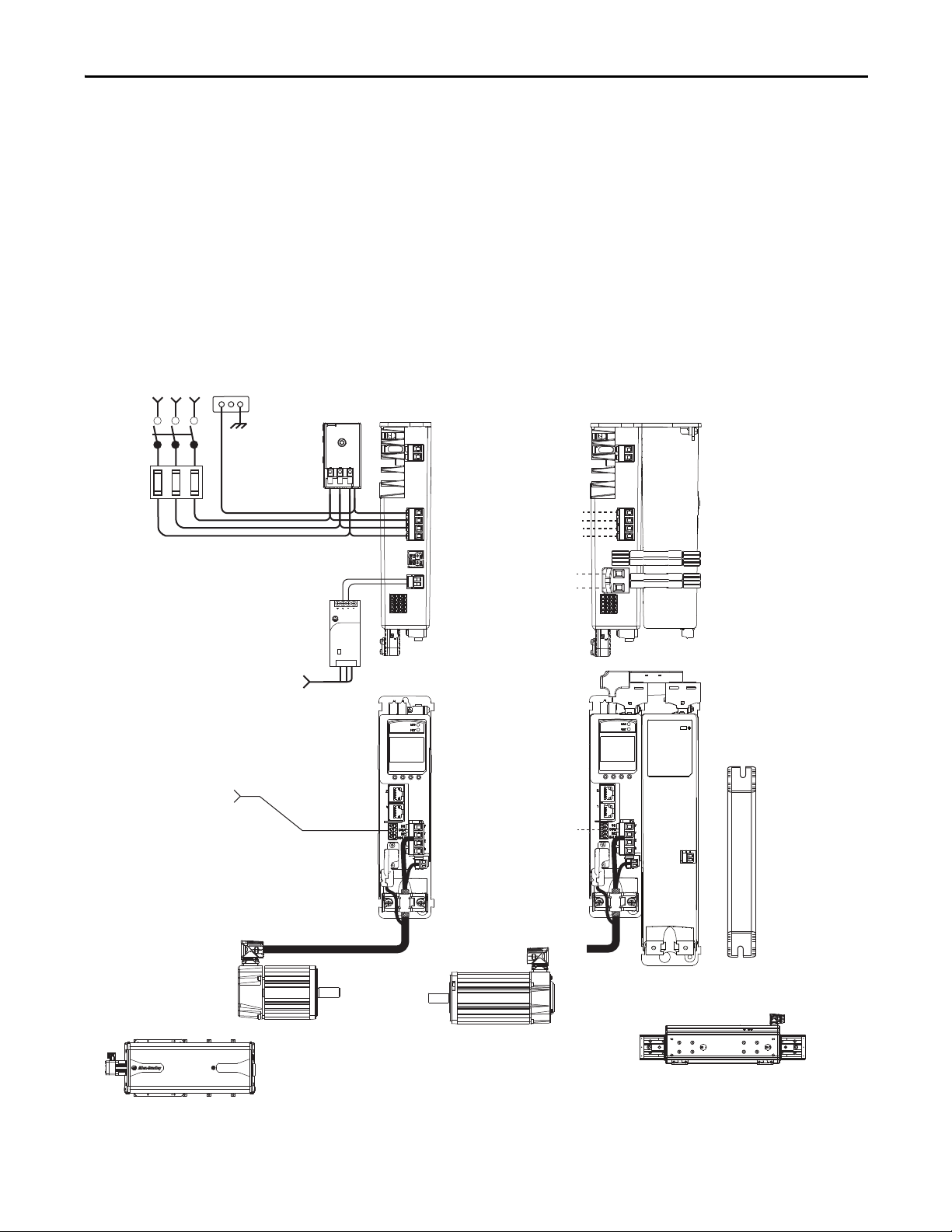
Single-phase or
Three-p hase
Input Power
Bulletin 2090
Single Motor Cable
Line
Disconnect
Device
Input
Fusin g
2198-Hxxx-ERSx Drive
(front view)
2097-Rx
Shunt Resistor
(optional component)
Kinetix VP (Bulletin VPL, VPF,
and VPS) Rotary Motors
(VPL-Bxxxx motor is shown)
2198-Hxxx-ERSx Drive
(top view)
AC Input Power
Bonded Cabinet
Ground Bus
2198-KITCON-DSL (shown)
Motor Feedback Connector Kit
or 2198-H2DCK Hiperface-to-DSL
Feedback Converter Kit
Mains AC and 24V input
wired to standard input
connectors.
2198-DBxx-F
AC Lin e Filter
(required for CE)
Shared DC (DC common bus)
Shared 24V (control power input)
2198-Hxxx-ERSx Drive (top view)
with 2198-CAPMOD-1300
Capacitor Module
2198-H0x0-x-x shared-bus
connection system for bussharing configurations.
Mains AC input wired to
standard input connector.
Digital Inputs
to Sensors and Control String
1606-XLxxx
24V DC Control, Digital Inputs,
and Motor Brake Power
(customer-supplied)
MP-Series (Bulletin MPAS, MPAR, MPAI) Linear Actuators
(1)
MPAS-B9xxx (ballscrew) Linear Stage is Shown
MP-Series (Bulletin MPL, MPM, MPF, MPS) Rotary Motors
(1)
(MPL-Bxxxx rotary motor is shown)
LDAT-Series Linear Thrusters
(1)
(LDAT-Sxxxxxx-xDx linear thruster is shown)
Typical Hardware Configurations
Typical Kinetix 5500 systems include single-phase and three-phase standalone
configurations, three-phase shared AC, shared AC/DC, shared DC, and shared
AC/DC hybrid configurations.
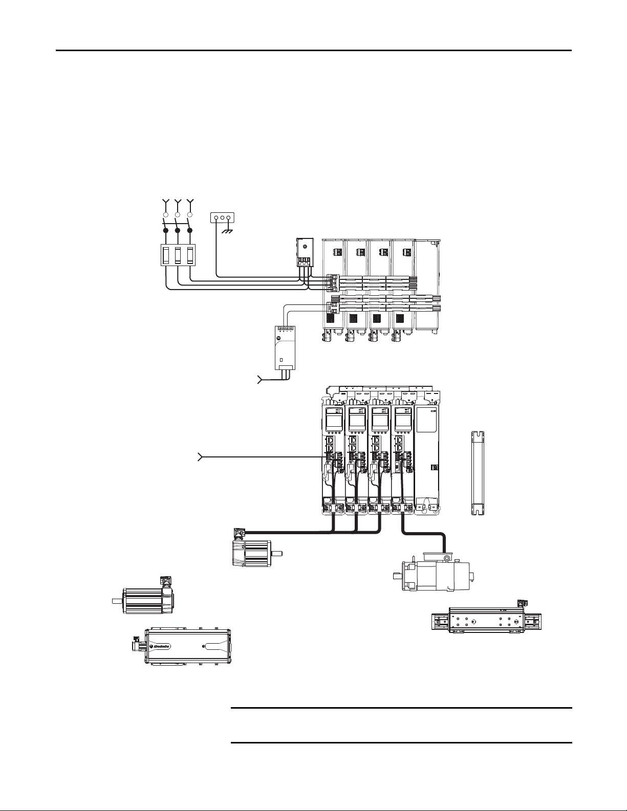
Standalone Configurations
In these examples, a single standalone drive is shown with and without the
Bulletin 2198 capacitor module.
Figure 1 - Typical Kinetix 5500 Standalone Installation
Allen-Bradley
1606-XL
Power Supply
Input
(1) Requires the 2198-H2DCK Hiperface-to-DSL feedback converter kit. LDAT-Series linear thrusters and MP-Series (200V-class) motors
and actuators require the 2198-H2DCK (series B or later) converter kit.
Rockwell Automation Publication 2198-UM001D-EN-P - May 2014 15
Page 16
Chapter 1 Start
1606-XL
Power Supply
Input
Allen-Bradley
Kinetix 5500 Servo Drives (top view)
(2198-H008-ERS drives shown)
2097-Rx
Shunt Resistor
(optional component)
Line
Disconnect
Device
Input
Fusing
Three-phase
Input Power
AC Input Power
Bonded Cabinet
Ground Bus
Kinetix 5500 Servo Drives (front view)
(2198-H008-ERS drives shown)
Induction
Rotary Motors
2198-DBxx-F
AC Line Filter
(required for CE)
Bulletin 2090
Single Motor Cables
Share d AC (mains AC input)
Shared 24V (control power input)
Shared-bus connection system
for bus-sharing configurations.
Digital Inputs
to Sensors and Control String
1606-XLxxx
24V DC Control, Digital Inputs,
and Motor Brake Power
(customer-supplied)
MP-Series (Bulletin MPAS, MPAR, MPAI) Linear Actuators
(1)
MPAS-B9xxx (ballscrew) Linear Stage is Shown
MP-Series (Bulletin MPL, MPM, MPF, MPS) Rotary Motors
(1)
(MPL-Bxxxx rotary motor is s hown)
2198-KITCON-DSL (shown)
Motor Feedback Connector Kit
or 2198-H2DCK Hiperface-to-DSL
Feedback Converter Kit
Kinetix VP (Bulletin VPL, VPF,
and VPS) Rotary Motors
(VPL-Bxxxx motor is shown)
LDAT-Series Linear Thrusters
(1)
(LDAT-Sxxxxxx-xDx linear thruster is shown)
IMPORTANT
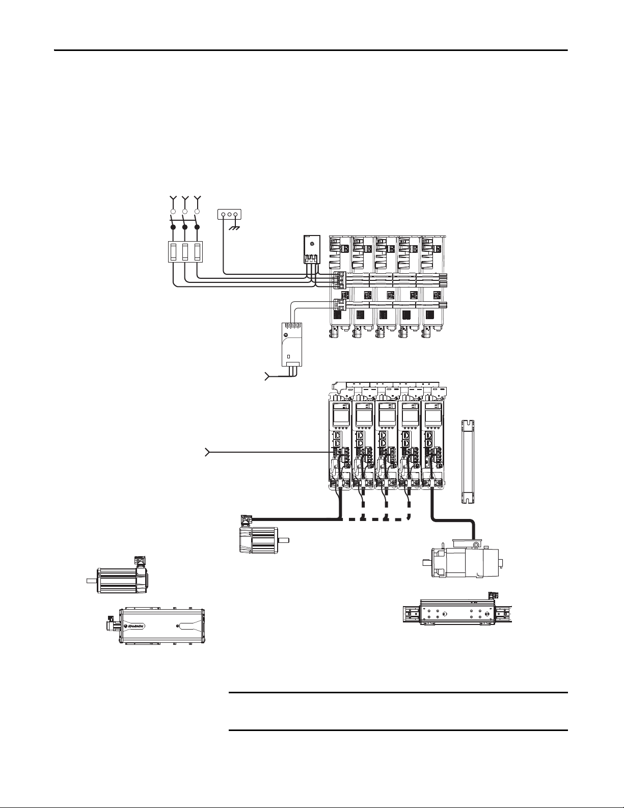
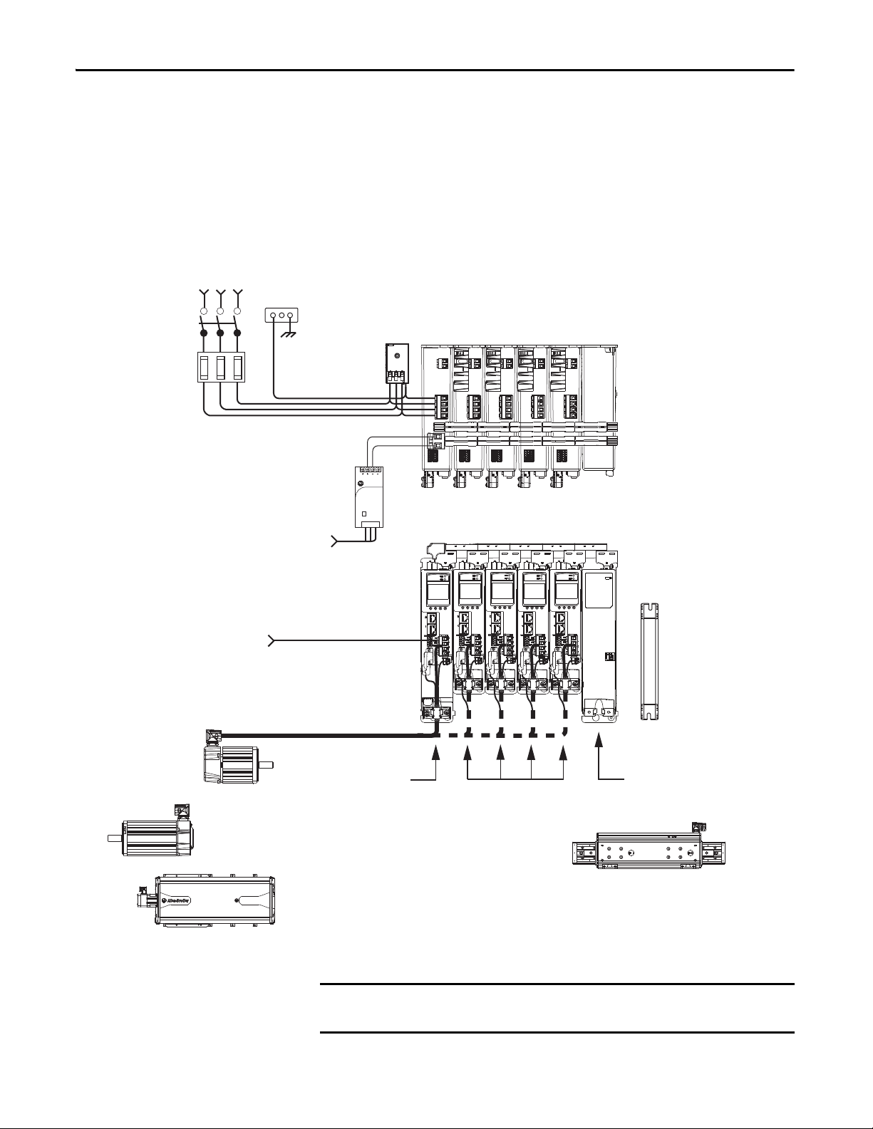
Shared AC Configurations
In this example, three-phase AC power and 24V control power is shared in a
multi-axis configuration. All drives must have the same power rating (catalog
number).
Figure 2 - Typical Shared AC Installations
(1) Requires the 2198-H2DCK Hiperface-to-DSL feedback converter kit. LDAT-Series linear thrusters and MP-Series (200V-class) motors
and actuators require the 2198-H2DCK (series B or later) converter kit.
In shared AC configurations, all drives must have the same power rating.
Shared AC configurations do not support Bulletin 2198 capacitor modules.
16 Rockwell Automation Publication 2198-UM001D-EN-P - May 2014
Page 17
2097-Rx
Shunt Resistor
(optional component)
Line
Disconnect
Device
Input
Fusing
Three-phase
Input Power
AC Input Power
Bonded Cabinet
Ground Bus
Induction
Rotary Motors
2198-DBxx-F
AC Lin e Filter
(required for CE)
Bulletin 2090
Single Motor Cables
Kinetix 5500 Servo Drives (top view)
(2198-H015-ERS drives shown)
Kinetix 5500 Servo Drives (front view)
(2198-H015-ERS drives shown)
Shared AC (mains AC input)
Shared DC (DC common bus)
Shared 24V (control power input)
2198-CAPMOD-1300 Capacitor Module
(optional component)
Shared-bus connection system for
bus-sharing configurations.
Digital Inputs
to Sensors and Control String
1606-XLxxx
24V DC Control, Digital Inputs,
and Motor Brake Power
(customer-supplied)
2198-KITCON-DSL (shown)
Motor Feedback Connector Kit
or 2198-H2DCK Hiperface-to-DSL
Feedback Converter Kit
MP-Series (Bulletin MPAS, MPAR, MPAI) Linear Actuators
(1)
MPAS-B9xxx (ballscrew) Linear Stage is Shown
MP-Series (Bulletin MPL, MPM, MPF, MPS) Rotary Motors
(1)
(MPL-Bxxxx rotary motor is shown)
Kinetix VP (Bulletin VPL, VPF,
and VPS) Rotary Motors
(VPL-Bxxxx motor is shown)
LDAT-Series Linear Thrusters
(1)
(LDAT-Sxxxxxx-xDx linear thruster is shown)
IMPORTANT
Start Chapter 1
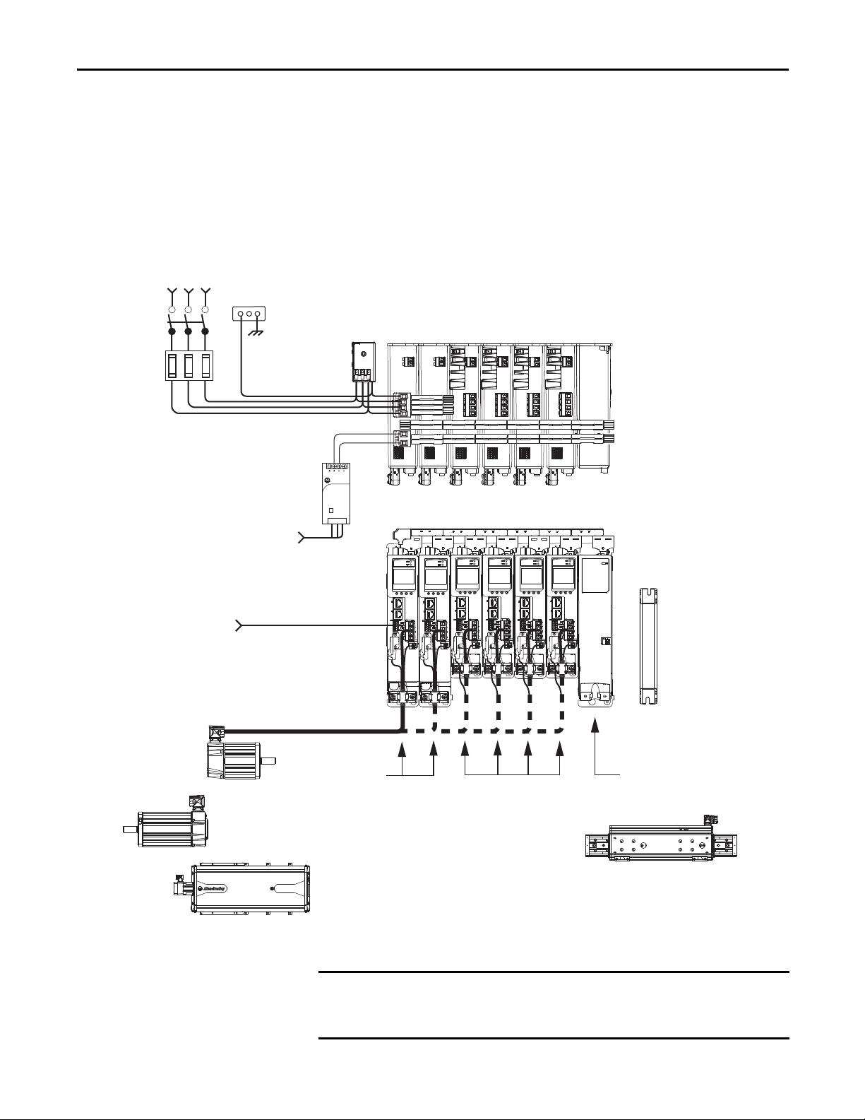
Shared AC/DC Configurations
In this example, three-phase AC input power, 24V control power, and DC bus
power are shared in a multi-axis configuration. All drives must be the same power
rating (catalog number).
Figure 3 - Typical Shared AC/DC Installations
Allen-Bradley
1606-XL
Power Supply
Input
(1) Requires the 2198-H2DCK Hiperface-to-DSL feedback converter kit. LDAT-Series linear thrusters and MP-Series (200V-class) motors
and actuators require the 2198-H2DCK (series B or later) converter kit.
In shared AC/DC configurations, all drives must have the same power rating
(catalog number).
Rockwell Automation Publication 2198-UM001D-EN-P - May 2014 17
Page 18
Chapter 1 Start
1606-XL
Power Supply
Input
Allen-Bradley
Kinetix 5500 Servo Drive System (top view)
2097-Rx
Shunt Resistor
(optional component)
Line
Disconnect
Device
Input
Fusin g
Three-phase
Input Power
2198-H040-ERS
Common-bus Leader Drive
AC Input Power
Bonded Cabinet
Ground Bus
Kinetix 5500 Servo Drive System (front view)
2198-H008-ERS
Common-bus
Followe r Drives
2198-DBxx-F
AC Lin e Filter
(required for CE)
Bulletin 2090 Single Motor Cables
Shared DC (DC common bus)
Shared 24V (control power input)
2198-CAPMOD-1300 Capacitor Module
(optional component)
Shared-bus connection system
for bus-sharing configurations.
Digital Inputs
to Sensors and Control String
1606-XLxxx
24V DC Control, Digital Inputs,
and Motor Brake Power
(customer-supplied)
2198-KITCON-DSL (shown)
Motor Feedback Connector Kit
or 2198-H2DCK Hiperface-to-DSL
Feedback Converter Kit
MP-Series (Bulletin MPAS, MPAR, MPAI) Linear Actuators
(1)
MPAS-B9xxx (ballscrew) Linear Stage is Shown
MP-Series (Bulletin MPL, MPM, MPF, MPS) Rotar y Motors
(1)
(MPL-Bxxxx rotary motor is shown)
Kinetix VP (Bulletin VPL, VPF,
and VPS) Rotary Motors
(VPL-Bxxxx motor is shown)
LDAT-Series Linear Thrusters
(1)
(LDAT-Sxxxxxx-xDx linear thruster is shown)
IMPORTANT
Shared DC Common-bus Configurations
In this multi-axis example, the common-bus leader (sourcing) drive receives
three-phase AC input power and supplies DC power to common-bus follower
(sinking) drives. The common-bus leader drive power rating is greater than or
equal to the power rating of each follower drive.
Figure 4 - Typical Shared DC Common-bus Installations
(1) Requires the 2198-H2DCK Hiperface-to-DSL feedback converter kit. LDAT-Series linear thrusters and MP-Series (200V-class) motors
and actuators require the 2198-H2DCK (series B or later) converter kit.
In shared DC common-bus configurations, the leader drive power rating must
be greater than or equal to the power rating of the follower drives.
18 Rockwell Automation Publication 2198-UM001D-EN-P - May 2014
Page 19
Start Chapter 1
Kinetix 5500 Servo Drive System (top view)
2097-Rx
Shunt Resistor
(optional component)
Line
Disconnect
Device
Input
Fusing
Three-phase
Input Power
Digital Inputs
to Sensors and Control String
2198-H040-ERS
Common-bus (converter)
Leader Drives
1606-XLxxx
24V DC Control, Digital Inputs,
and Motor Brake Power
(customer-supplied)
AC Input Power
Bonded Cabinet
Ground Bus
Kinetix 5500 Servo Drive System (front view)
2198-H008-ERS
Common-bus (inverter)
Follower Drives
2198-DBxx-F
AC Lin e Filter
(required for CE)
Bulletin 2090 Single Motor Cables
Share d AC (mains AC input)
Shared DC (DC common bus)
Shared 24V (control power input)
Shared-bus connection system for
bus-sharing configurations.
2198-CAPMOD-1300 Capacitor Module
(optional component)
2198-KITCON-DSL (shown)
Motor Feedback Connector Kit
or 2198-H2DCK Hiperface-to-DSL
Feedback Converter Kit
MP-Series (Bulletin MPAS, MPAR, MPAI) Linear Actuators
(1)
MPAS-B9xxx (ballscrew) Linear Stage is Shown
MP-Series (Bulletin MPL, MPM, MPF, MPS) Rotary Motors
(1)
(MPL-Bxxxx rotary motor is s hown)
Kinetix VP (Bulletin VPL, VPF,
and VPS) Rotary Motors
(VPL-Bxxxx motor is shown)
LDAT-Series Linear Thrusters
(1)
(LDAT-Sxxxxxx-xDx linear thruster is shown)
IMPORTANT
Shared AC/DC Hybrid Configuration
In this multi-axis example, three-phase AC input power is supplied to two
converter drives. The converter drive ratings must be the same, and greater than
or equal to the power ratings of the inverter drives. This parallel converter
configuration increases the DC power supplied to the inverter drives.
Figure 5 - Typical Shared AC/DC Bus Hybrid Installations
Allen-Bradley
1606-XL
Power Supply
Input
(1) Requires the 2198-H2DCK Hiperface-to-DSL feedback converter kit. LDAT-Series linear thrusters and MP-Series (200V-class) motors
and actuators require the 2198-H2DCK (series B or later) converter kit.
Rockwell Automation Publication 2198-UM001D-EN-P - May 2014 19
In shared AC/DC hybrid configuration, the converter drives must have the same
power rating and must be greater than or equal to the power ratings of the
inverter drives.
Page 20
Chapter 1 Start
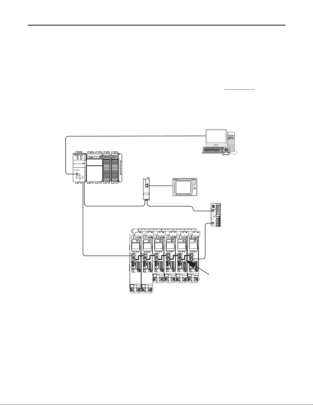
CompactLog ix 5370 Cont roller
Logix Designer
Application
1585J-M8CBJM-x
Ethernet (shielded) Cable
1734-AENTR POINT I/O™
EtherNet/IP Adapter
CompactLogix Controller Programming Network
Panel View™ Pl us
Display Terminal
1585J-M8CBJM-OM3
0.3 m (1.0 ft) Ethernet cable
for drive-to-drive connections.
Kinetix 5500 Servo Drive System
Typical Communication Configurations
The Kinetix 5500 drives support any Ethernet topology including linear, ring,
and star.
These examples feature the CompactLogix 5370 programmable automation
controllers (catalog number 1769-L36ERM) with support for Integrated Motion
over the EtherNet/IP network. Controller features include the following:
• Supports up to 16 axes
• Supports up to 48 devices in linear configurations
• Dual-port connectivity to support device-level ring (DLR) topology
Refer to CompactLogix Controllers Specifications Technical Data, publication
1769-TD005
, for more information on CompactLogix 5370 L1, L2, and L3
controllers.
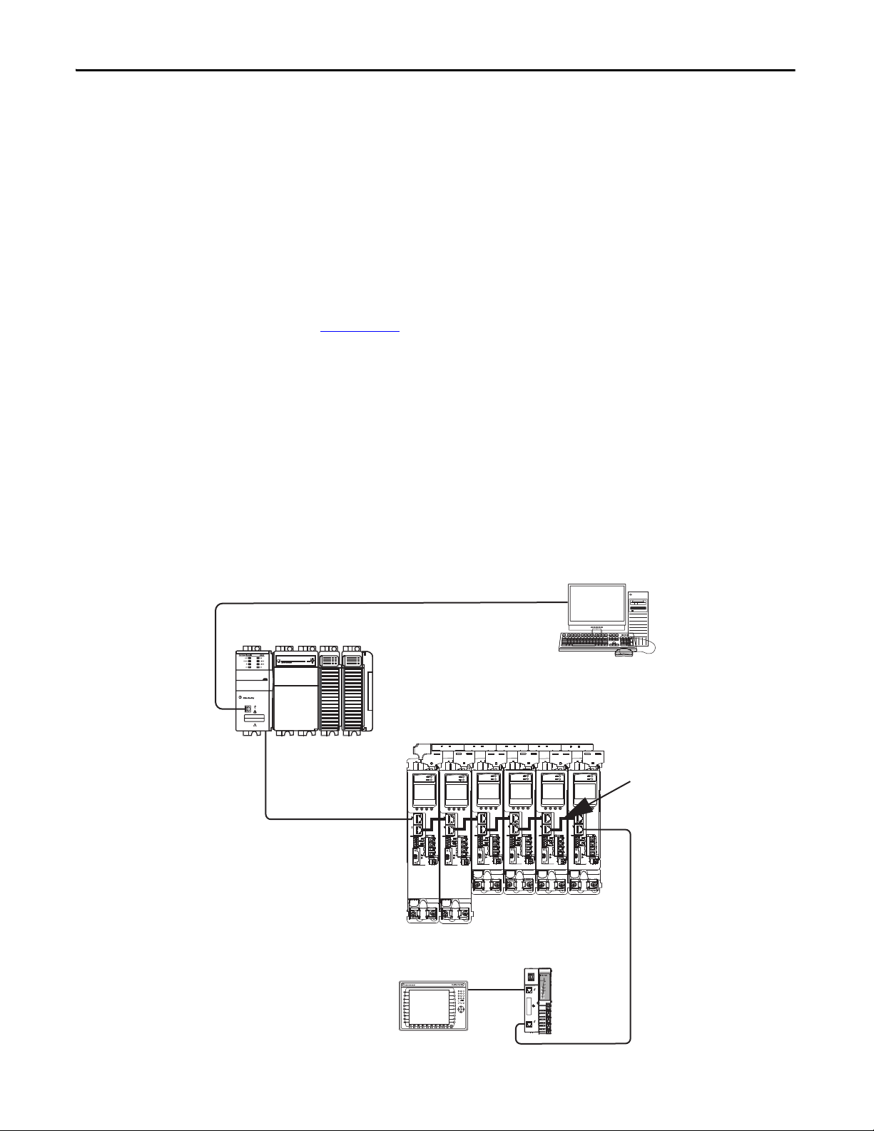
Linear Topology
In this example, all devices are connected in linear topology. The Kinetix 5500
drives include dual-port connectivity, however, if any device becomes
disconnected, all devices downstream of that device lose communication. Devices
without dual ports must include the 1783-ETAP module or be connected at the
end of the line.
00:00:BC:2E:69:F6
1 (Front)
2 (Rear)
Figure 6 - Kinetix 5500 Linear Communication Installation
1734-AENTR
02
0
POINT I O
Module
Status
Network
Activity
Network
Status
Point Bus
Status
Link 1
Activity/
System
Status
Power
Field
Power
Link 2
Activity/
Status
20 Rockwell Automation Publication 2198-UM001D-EN-P - May 2014
Page 21
Start Chapter 1
1 (Front)
2 (Rear)
00:00:BC:2E:69:F6
02
0
1734-AENTR
Module
Status
Network
Activity
Network
Status
Point Bus
Status
System
Power
Field
Power
POINT I O
Link 1
Activity/
Status
Link 2
Activity/
Status
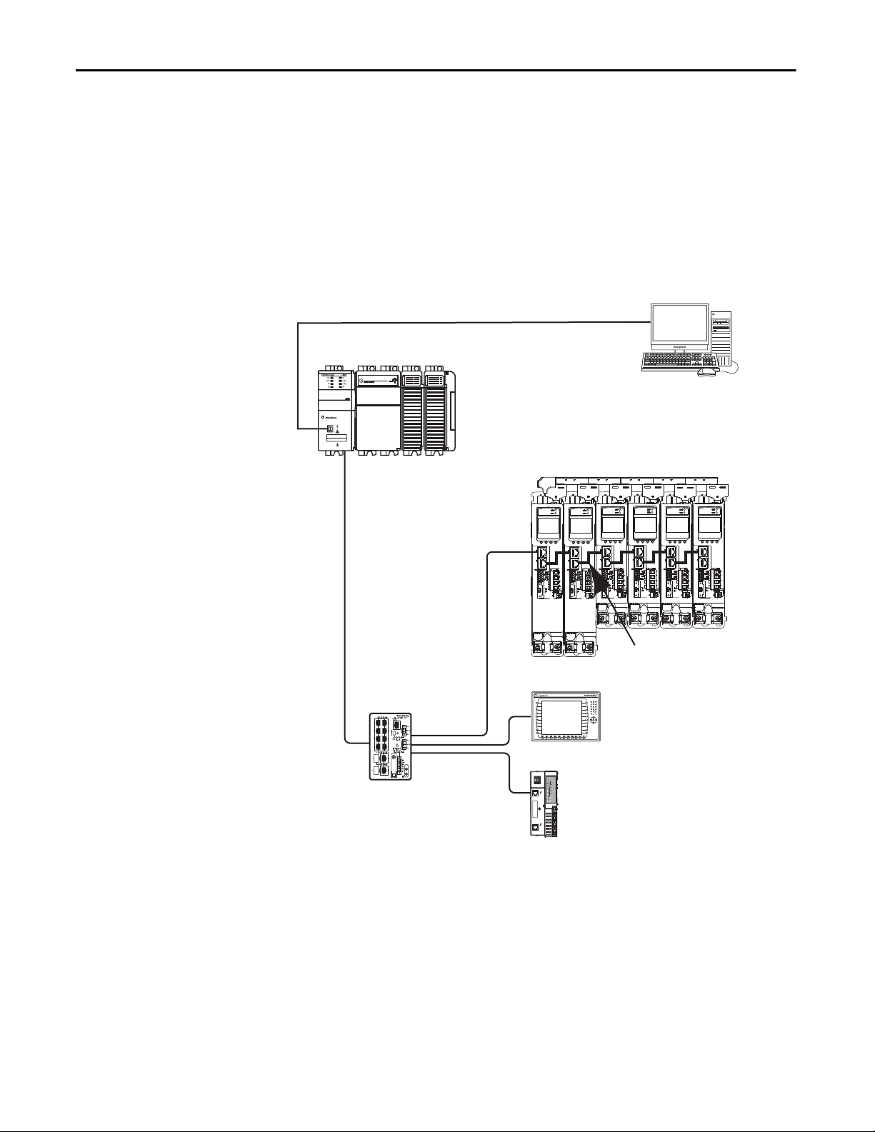
1734-AENTR POINT I/O
EtherNet/IP Adapter
CompactLogix Controller Programming Network
1783-ETAP
Module
1585J-M8CBJM-OM3
0.3 m (1.0 ft) Ethernet cable
for drive-to-drive connections.
Panel View Plus
Display Terminal
Kinetix 5500 Servo Drive System
CompactLogix 5370 Controller
Logix Designer
Application
1585J-M8CBJM-x Ethernet
(shielded) Cable
Ring Topology
In this example, the devices are connected by using ring topology. If only one
device in the ring is disconnected, the rest of the devices continue to
communicate. For ring topology to work correctly, a device level ring (DLR)
supervisor is required (for example, the Bulletin 1783 ETAP device). DLR is an
ODVA standard. For more information, refer to the EtherNet/IP Embedded
Switch Technology Application Guide, publication ENET-AP005
Devices without dual ports, for example the display terminal, require a
1783-ETAP module to complete the network ring.
Figure 7 - Kinetix 5500 Ring Communication Installation
.
Rockwell Automation Publication 2198-UM001D-EN-P - May 2014 21
Page 22
Chapter 1 Start
1 (Front)
2 (Rear)
00:00:BC:2E:69:F6
1585J-M8CBJM-x
Ethernet (shielded) Cable
1734-AENTR POINT I/O
EtherNet/IP Adap ter
CompactLogix Controller Programming Network
PanelView Plus
Display Terminal
1783-BMS
Stratix 5700™
Switch
1585J-M8CBJM-OM3
0.3 m (1.0 ft) Ethernet cable
for drive-to-drive connections.
Kinetix 5500 Servo Drive System
CompactLogix 5370 Controller
Logix Designer
Application
Star Topology
In this example, the devices are connected by using star topology. Each device is
connected directly to the switch.
Kinetix 5500 drives have dual ports, so linear topology is maintained from driveto-drive, but Kinetix 5500 drives and other devices operate independently. The
loss of one device does not impact the operation of other devices.
Figure 8 - Kinetix 5500 Star Communication Installation
22 Rockwell Automation Publication 2198-UM001D-EN-P - May 2014
Page 23
Start Chapter 1
1 (Front)
2 (Rear)
00:00:BC:2E:69:F6
1606-XL
Power Supply
Input
Allen-Bradley
1585J-M8CBJM-x
Ethernet (shielded) Cable
CompactLogix 5370 Controller,
ControlLogix 1756-L7x Controller, or
GuardLogix 1756-L7xS Safety Controller
(CompactLogix controller is shown)
Logix Designer
Application
(version 21.0 or later)
AC Input Power
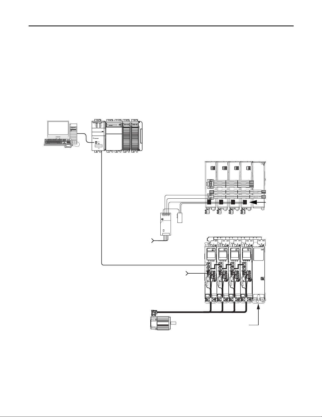
Safety
Device
2198-Hxxx-ERS Servo Drives
(top view)
2198-Hxxx-ERS Servo Drives
(front view)
Digital Inputs to Sensors and Control String
1606-XLxxx
24V DC Control, Digital Inputs,
and Motor Brake Power
(customer-supplied)
Kinetix VP
Servo Motors
2198-CAPMOD-1300 Capacitor Module
(optional component)
Module Definition
Configured with
Motion-only
Connection
Safe Torque-off
(STO) Connectors
Safe Torque-off Configurations
Kinetix 5500 servo drives are available with safe torque-off via hardwired
connections or integrated over the EtherNet/IP network. These examples
illustrate the safe torque-off configuration options.
Hardwired Safety Configuration
The 2198-Hxxx-ERS drives use the safe torque-off (STO) connector for
cascading hardwired safety connections from drive-to-drive.
Figure 9 - Safe Torque-off (hardwired) Configuration
Rockwell Automation Publication 2198-UM001D-EN-P - May 2014 23
Page 24
Chapter 1 Start
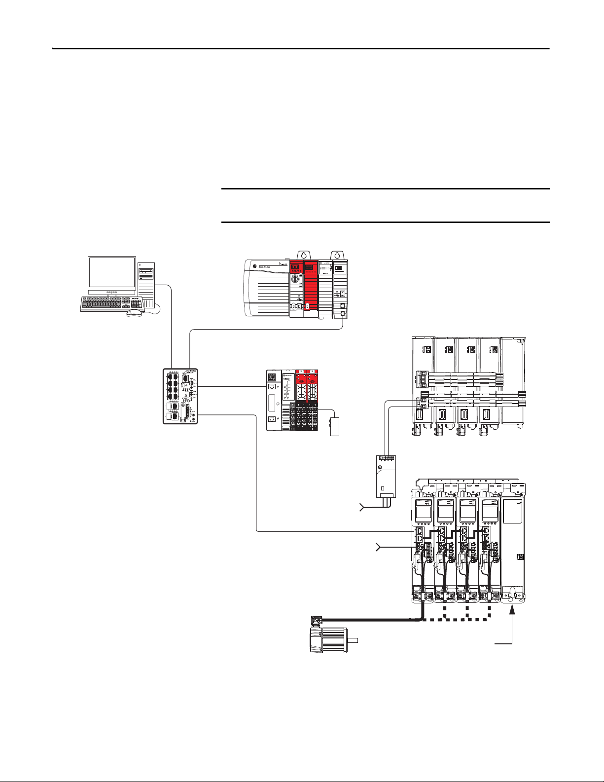
IMPORTANT
1606-XL
Power Supply
Input
Allen-Bradley
LNK1LNK2NET OK
EtherNet/IP
1
2
1585J-M8CBJM-x
Ethernet (shielded) Cable
GuardLogix 1756-L7xS Safety Controller
Logix Designer
Application
(version 24.0 or later)
AC Inp ut Power
2198-Hxxx-ERS2 Servo Drives
(top view)
2198-Hxxx-ERS2 Servo Drives
(front view)
Digital Inputs to Sensors and Control String
1606-XLxxx
24V DC Control, Digital Inputs,
and Motor Brake Power
(customer-supplied)
Kinetix VP
Servo Motors
2198-CAPMOD-1300 Capacitor Module
(optional component)
1783-BMS
Stratix 5700
Switch
Module Definition
Configured with
Motion and Safety
Conne ction
1734-AENTR
POINT Guard I/O
EtherNet/IP Adapter
Safety
Device
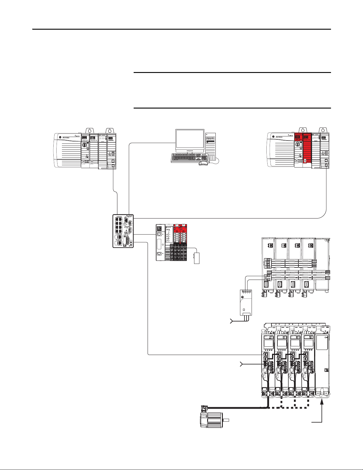
Integrated Safety Configurations
The 1756-L7xS GuardLogix safety controller issues the safe torque-off (STO)
command over the EtherNet/IP network and the 2198-Hxxx-ERS2 integrated
safety drive executes the command.
In this example, a single GuardLogix safety controller makes a Motion and Safety
connection with the 2198-Hxxx-ERS2 integrated safety drives.
If only one controller is used in an application with Motion and Safety
connections, it must be a 1756-L7xS GuardLogix safety controller.
Figure 10 - Motion and Safety Configuration (single controller)
24 Rockwell Automation Publication 2198-UM001D-EN-P - May 2014
Page 25
Start Chapter 1
IMPORTANT
1585J-M8CBJM-x
Ethernet (shielded) Cable
GuardLogix 1756-L7xS Controller
Logix Designer
Application
(version 24.0 or later)
AC Inp ut Power
2198-Hxxx-ERS2 Servo Drives
(top view)
2198-Hxxx-ERS2 Servo Drives
(front view)
Digital Inputs to Sensors and Control String
1606-XLxxx
24V DC Control, Digital Inputs,
and Motor Brake Power
(customer-supplied)
Kinetix VP
Servo Motors
2198-CAPMOD-1300 Capacitor Module
(optional component)
1734-AENTR
POINT Guard I/O
EtherNet/IP Adapter
1783-BMS
Stratix 5700
Switch
CompactLogix 5370 Controller or
ControlLogix 1756-L7x Controller
(ControlLogix controller is shown)
Motion Program
Module Definition
Configured with
Motion only
Conne ction
Safety Program
Module Definition
Configured with
Safety only
Conne ction
Safety
Device
In this example, a non-safety controller makes the Motion-only connection and a
separate GuardLogix safety controller makes the Safety-only connection with
2198-Hxxx-ERS2 integrated safety drives.
If two controllers are used in an application with Motion-only and Safetyonly connections, the Safety-only connection must be a 1756-L7xS
GuardLogix safety controller and the Motion-only connection must be a
ControlLogix 1756-L7x or CompactLogix 5370 controller.
Figure 11 - Motion and Safety Configuration (multi-controller)
LNK1LNK2NET OK
EtherNet/IP
EtherNet/IP
LNK1LNK2NET OK
2
1
2
1
Allen-Bradley
1606-XL
Power Supply
Input
Rockwell Automation Publication 2198-UM001D-EN-P - May 2014 25
Page 26

Chapter 1 Start
Catalog Number Explanation
Drive Cat. No.
(hardwired STO)
2198-H003-ERS 2198-H003-ERS2
2198-H008-ERS 2198-H008-ERS2
2198-H015-ERS 2198-H015-ERS2
2198-H025-ERS 2198-H025-ERS2
2198-H040-ERS 2198-H040-ERS2
2198-H070-ERS 2198-H070-ERS2 3
Capacitor Module
Cat. No.
2198-CAPMOD-1300 2 650V DC, nom 1360 μF, min
Kinetix 5500 drive catalog numbers and performance descriptions.
Table 2 - Kinetix 5500 Drive Catalog Numbers
Drive Cat. No.
(integrated STO)
Frame Size Input Voltage
1
2
195…264V rms, single-phase
195…264V rms, three-phase
324…528V rms, three-phase
195…264V rms, three-phase
324…528V rms, three-phase
Table 3 - Drive Components Catalog Numbers
Frame Size Rated Voltage Capacitance
Continuous Output
Power
kW
0.2 kW
0.3 kW
0.6 kW
0.5 kW
0.8 kW
1.6 kW
1.0 kW
1.5 KW
3.2 kW
2.4 kW
5.1 kW
4.0 kW
8.3 kW
7.0 kW
14.6 kW
Continuous Output
Current
A 0-pk
1.4
3.5
7.1
11.3
18.4
32.5
Table 4 - Shared-bus Connector Kit Catalog Numbers
Kit Cat. No. Frame Size Application Description
2198-H040-ADP-IN Frame 1 or 2 First drive
2198-H040-A-T
2198-H040-D-T DC sharing only DC bus T-connector
2198-H040-P-T Control power sharing only Control power T-connector
2198-H040-AD-T AC and DC bus sharing AC and DC bus T-connectors
2198-H040-AP-T AC and control power sharing AC and control power T-connectors
2198-H040-DP-T DC and control power sharing DC and control power T-connectors
2198-H040-ADP-T AC, DC, and control power sharing AC, DC, and control power T-connectors
2198-H070-ADP-IN
2198-H070-A-T
2198-H070-D-T DC sharing only DC bus T-connector
2198-H070-P-T Control power sharing only Control power T-connector
2198-H070-AD-T AC and DC bus sharing AC and DC bus T-connectors
2198-H070-AP-T AC and control power sharing AC and control power T-connectors
2198-H070-DP-T DC and control power sharing DC and control power T-connectors
2198-H070-ADP-T AC, DC, and control power sharing AC, DC, and control power T-connectors
Next drive is…
Frame 1 drives:
2198-H003-ERSx
2198-H008-ERSx
Frame 2 drives:
2198-H015-ERSx
2198-H025-ERSx
2198-H040-ERSx
Frame 3 drive:
2198-H070-ERSx
Next drive is…
Frame 3 drives:
2198-H070-ERSx
AC sharing only AC bus T-connector
First drive
AC sharing only AC bus T-connector
• Mains AC input wiring connector
• 24V DC input wiring connector
• DC bus T-connector
• Mains AC input wiring connector
• 24V DC input wiring connector
• DC bus T-connector
26 Rockwell Automation Publication 2198-UM001D-EN-P - May 2014
Page 27

Start Chapter 1
Agency Compliance
If this product is installed within the European Union and has the CE mark, the
following regulations apply.
ATT EN TI ON : Meeting CE requires a grounded system, and the method of
grounding the AC line filter and drive must match. Failure to do this renders the
filter ineffective and can cause damage to the filter. For grounding examples,
refer to Grounded Power Configurations
on page 69.
For more information on electrical noise reduction, refer to the System Design
for Control of Electrical Noise Reference Manual, publication GMC-RM001
.
To meet CE requirements, these requirements apply:
• Install an AC line filter (catalog number 2198-DBxx-F) for input power as
close to the Kinetix 5500 drive as possible.
• Bond drive, capacitor module, and line filter grounding screws by using a
braided ground strap as shown in Figure 39 on page 73
.
• Use Bulletin 2090 single motor cables with Kinetix VP servo motors. Use
Bulletin 2090 motor power/brake and feedback cables for other
compatible Allen-Bradley® motors and actuators.
• Combined motor cable length for all axes on the same DC bus must not
exceed 250 m (820 ft). Drive-to-motor cables must not exceed 50 m
(164 ft); however, use of continuous-flex cable and 2198-H2DCK
converter kit limits the maximum length.
Table 5 - Drive-to-Motor Maximum Cable Length
Kinetix VP Servo Motors Other Compatible Rotary Motors and Linear Actuators
Kinetix 5500 Servo Drive
Cat. No.
2198-H003-ERSx
2198-H008-ERSx
2198-H015-ERSx
2198-H025-ERSx
2198-H040-ERSx
2198-H070-ERSx 50 (164)
(1) Requires use of the 2198-H2DCK Hiperface- to-DSL feedback converter kit.
(2) Can b e used to repla ce Bulletin 2090 motor po wer/brake cabl es in 2198-H2 DCK convert er kit applic ations to inc rease the maxi mum length up to 50 m (164 ft). Applie s to only power /brake cables. Refer to
Motor Power/Brake Cable Preparation
Standard (non-flex) Cables
(cat. no. 2090-CSxM1DF-xxAAxx)
m (ft)
50 (164) 30 (98.4)
50 (164)
on page 89 for more information.
(2)
Continuous-flex Cables
(cat. no. 2090-CSBM1DF-xxAFxx)
m (ft)
Motor Power/brake Cables (cat. no. 2090-CPxM7DF-xxAxxx)
Feedback Cables (cat. no. 2090-CFBM7DF-CEAxxx)
m (ft)
20 (65.6)
(1)
• Install the Kinetix 5500 system inside an approved enclosure. Run input
power wiring in conduit (grounded to the enclosure) outside of the
enclosure. Separate signal and power cables.
• Segregate input power wiring from control wiring and motor cables.
Refer to Appendix A on page 189
for input power wiring and drive/motor
interconnect diagrams.
Rockwell Automation Publication 2198-UM001D-EN-P - May 2014 27
Page 28

Chapter 1 Start
Notes:
28 Rockwell Automation Publication 2198-UM001D-EN-P - May 2014
Page 29
Chapter 2
Planning the Kinetix 5500 Drive
System Installation
This chapter describes system installation guidelines used in preparation for
mounting your Kinetix 5500 drive components.
Top ic Pa ge
System Design Guidelines 30
Electrical Noise Reduction 36
ATT EN TI ON : Plan the installation of your system so that you can perform all
cutting, drilling, tapping, and welding with the system removed from the
enclosure. Because the system is of the open type construction, be careful to
keep metal debris from falling into it. Metal debris or other foreign matter can
become lodged in the circuitry and result in damage to the components.
Rockwell Automation Publication 2198-UM001D-EN-P - May 2014 29
Page 30

Chapter 2 Planning the Kinetix 5500 Drive System Installation
IMPORTANT
System Design Guidelines
Use the information in this section when designing your enclosure and planning
to mount your system components on the panel.
For on-line product selection and system configuration tools, including
AutoCAD (DXF) drawings of the product, refer to
http://www.rockwellautomation.com/en/e-tools
.
System Mounting Requirements
• To comply with UL and CE requirements, the Kinetix 5500 drive systems
must be enclosed in a grounded conductive enclosure offering protection
as defined in standard EN 60529 (IEC 529) to IP54 such that they are not
accessible to an operator or unskilled person. A NEMA 4X enclosure
exceeds these requirements providing protection to IP66.
• The panel you install inside the enclosure for mounting your system
components must be on a flat, rigid, vertical surface that won’t be subjected
to shock, vibration, moisture, oil mist, dust, or corrosive vapors.
• Size the drive enclosure so as not to exceed the maximum ambient
temperature rating. Consider heat dissipation specifications for all drive
components.
• Combined motor power cable length for all axes on the same DC bus must
not exceed 250 m (820 ft). Drive-to-motor cables must not exceed 50 m
(164 ft), however use of continuous-flex cable and 2198-H2DCK
converter kit limits the maximum length. Refer to Ta b l e 5
specifications by frame size.
on page 27 for
System performance was tested at these cable length specifications.
These limitations also apply when meeting CE requirements.
• Ethernet cable lengths connecting drive-to-drive, drive-to-controller, or
drive-to-switch must not exceed 100 m (328 ft).
• Registration and digital input cables greater than 30 m (98.4 ft) must be
shielded.
• Segregate input power wiring from control wiring and motor cables.
• Use high-frequency (HF) bonding techniques to connect the modules,
enclosure, machine frame, and motor housing, and to provide a lowimpedance return path for high-frequency (HF) energy and reduce
electrical noise.
Bond drive, capacitor module, and line filter grounding screws by using a
braided ground strap as shown in Figure 39 on page 73
Refer to the System Design for Control of Electrical Noise Reference Manual,
publication GMC-RM001
reduction.
, to better understand the concept of electrical noise
.
30 Rockwell Automation Publication 2198-UM001D-EN-P - May 2014
Page 31

Planning the Kinetix 5500 Drive System Installation Chapter 2
IMPORTANT
IMPORTANT
IMPORTANT
EXAMPLE
IMPORTANT
Transformer Selection
The servo drive does not require an isolation transformer for three-phase input
power. However, a transformer can be required to match the voltage
requirements of the drive to the available service.
To size a transformer for the main AC power inputs, refer to the Kinetix 5500
power specifications in the Kinetix Servo Drives Technical Data, publication
GMC-TD003
.
When using an autotransformer, make sure that the phase to neutral/ground
voltage does not exceed the input voltage ratings of the drive.
Use a form factor of 1.5 for three-phase power (where form factor is used to
compensate for transformer, drive module, and motor losses, and to account
for utilization in the intermittent operating area of the torque speed curve).
150 KVA, max and 3% impedance, min
Sizing a transformer to the voltage requirements of this drive:
2198-H040-ERSx = 8.4 kW = 12.6 KVA transformer.
Circuit Breaker/Fuse Selection
The Kinetix 5500 drives use internal solid-state motor short-circuit protection
and, when protected by suitable branch circuit protection, are rated for use on a
circuit capable of delivering up to 200,000 A.
While circuit breakers offer some convenience, there are limitations for their use.
Circuit breakers do not handle high current inrush as well as fuses.
UL has not approved circuit breakers for use as branch circuit protection for
Kinetix 5500 drive systems.
Make sure the selected components are properly coordinated and meet
acceptable codes including any requirements for branch circuit protection.
Evaluation of the short-circuit available current is critical and must be kept below
the short-circuit current rating of the circuit breaker.
Refer to Power Wiring Examples
ATT EN TI ON : Do not use circuit protection devices on the output of an AC drive
as an isolating disconnect switch or motor overload device. These devices are
designed to operate on sine wave voltage and the drive’s PWM waveform does
not allow it to operate properly. As a result, damage to the device occurs.
Rockwell Automation Publication 2198-UM001D-EN-P - May 2014 31
, on page 190, for the wiring diagram.
Page 32

Chapter 2 Planning the Kinetix 5500 Drive System Installation
Standalone Drive Systems
Table 6 - Fuse Selection (Bussmann part numbers)
Kinetix 5500 Drive Cat. No. Three-phase Single-phase
2198-H003-ERSx KTK-R-3 KTK-R-2
2198-H008-ERSx KTK-R-7 KTK-R-5
2198-H015-ERSx KTK-R-15 KTK-R-10
2198-H025-ERSx KTK-R-20
2198-H070-ERSx LPJ-35SP
Table 7 - Circuit Breaker Selection (Allen-Bradley catalog numbers)
Kinetix 5500 Drive Cat. No. Three-phase
2198-H003-ERSx 140U-D6D3-B20 140U-D6D2-B10
2198-H008-ERSx 140U-D6D3-B60 140U-D6D2-B20
2198-H015-ERSx 140U-D6D3-C12 140U-D6D2-B80
2198-H025-ERSx 140U-D6D3-C20
2198-H070-ERSx N/A
N/A2198-H040-ERSx KTK-R-25
(1)
Single-phase
N/A2198-H040-ERSx 140U-D6D3-C25
(1)
(1) UL has not approved circuit breakers for use as branch circuit protection for Kinetix 5500 drive systems.
Shared DC (common-bus) Drive Systems
Table 8 - Fuse Selection (Bussmann part numbers)
Kinetix 5500 Drive Cat. No. Three-phase
2198-H003-ERSx
2198-H008-ERSx
2198-H015-ERSx KTK-R-15
2198-H025-ERSx KTK-R-20
2198-H040-ERSx KTK-R-25
2198-H070-ERSx LPJ-35SP
Table 9 - Circuit Breaker Selection (Allen-Bradley catalog numbers)
Kinetix 5500 Drive Cat. No. Three-phase
2198-H003-ERSx
2198-H008-ERSx
2198-H015-ERSx 140U-D6D3-C15
2198-H025-ERSx 140U-D6D3-C20
2198-H040-ERSx 140U-D6D3-C25
2198-H070-ERSx N/A
KTK-R-10
(1)
N/A
(1) UL has not approved circuit breakers for use as branch circuit protection for Kinetix 5500 drive systems.
32 Rockwell Automation Publication 2198-UM001D-EN-P - May 2014
Page 33

Planning the Kinetix 5500 Drive System Installation Chapter 2
Shared AC Drive Systems
Table 10 - Fuse Selection (Bussmann part numbers)
Kinetix 5500 Drive
Cat. No.
2 Axes 3 Axes 4 Axes 5 Axes
2198-H003-ERSx KTK-R-15
2198-H008-ERSx KTK-R-15
2198-H015-ERSx KTK-R-20 KTK-R-25 N/A
2198-H025-ERSx KTK-R-30 N/A
2198-H040-ERSx LPJ-35SP LPJ-45SP N/A
2198-H070-ERSx LPJ-60SP N/A
Table 11 - Circuit Breaker Selection (Allen-Bradley catalog numbers)
Kinetix 5500 Drive
Cat. No.
2198-H003-ERSx
2198-H008-ERSx
2198-H015-ERSx 140U-D6D3-C15 140U-D6D3-C20 N/A
2198-H025-ERSx 140U-D6D3-C25 140U-D6D3-C30 N/A
2198-H040-ERSx N/A
2198-H070-ERSx N/A
(1) UL has not approved circuit breakers for use as branch circuit protection for Kinetix 5500 drive systems.
2 Axes
N/A
(1)
3 Axes
(1)
4 Axes
(1)
5 Axes
(1)
Shared AC/DC and Hybrid Systems
Table 12 - Fuse Selection (Bussmann part numbers)
Kinetix 5500 Drive
Cat. No.
2198-H003-ERSx KTK-R -10 KTK-R -15
2198-H008-ERSx KTK-R-15 KTK-R-20
2198-H015-ERSx KTK-R-20 N/A
2198-H025-ERSx KTK-R-30 N/A
2198-H040-ERSx KTK-R-30 LPJ-45SP LPJ-50SP N/A
2198-H070-ERSx LPJ-50SP N/A
Kinetix 5500 Drive
Cat. No.
2198-H003-ERSx N/A
2198-H008-ERSx N/A
2198-H015-ERSx 140U-D6D3-C15 140U-D6D3-C20 N/A
2198-H025-ERSx 140U-D6D3-C20 140U-D6D3-C30 N/A
2198-H040-ERSx 140U-D6D3-C30 N/A
2198-H070-ERSx N/A
2 Axes 3 Axes 4 Axes 5 Axes 6 Axes 7 Axes 8 Axes
Table 13 - Circuit Breaker Selection (Allen-Bradley catalog numbers)
2 Axes
(1)
3 Axes
(1)
4 Axes
(1)
5 Axes
(1)
6 Axes
(1)
7 Axes
(1)
8 Axes
(1)
(1) UL has not approved circuit breakers for use as branch circuit protection for Kinetix 5500 drive systems.
Rockwell Automation Publication 2198-UM001D-EN-P - May 2014 33
Page 34

Chapter 2 Planning the Kinetix 5500 Drive System Installation
A =
0.38Q
1.8T - 1.1
A =
4.08Q
T - 1.1
A =
0.38 (416)
1.8 (30) - 1.1
= 2.99 m
2
Enclosure Selection
This example is provided to assist you in sizing an enclosure for your
Kinetix 5500 drive system. You need heat dissipation data from all components
planned for your enclosure to calculate the enclosure size (refer to Ta b l e 1 4
With no active method of heat dissipation (such as fans or air conditioning)
either of the following approximate equations can be used.
Metric Standard English
).
Where T is temperature difference between inside air and
outside ambient (°C), Q is heat generated in enclosure
(Watts), and A is enclosure surface area (m
surface of all six sides of an enclosure is calculated as
A = 2dw + 2dh + 2wh A = (2dw + 2dh + 2wh) /144
Where d (depth), w (width), and h (height) are in meters. Where d (depth), w (width), and h (height) are in inches.
2
). The exterior
Where T is temperature difference between inside air and
outside ambient (°F), Q is heat generated in enclosure
(Watts), and A is enclosure surface area (ft2). The exterior
surface of all six sides of an enclosure is calculated as
If the maximum ambient rating of the Kinetix 5500 drive system is 50 °C
(122 °F) and if the maximum environmental temperature is 20 °C (68 °F), then
T=30. In this example, the total heat dissipation is 416 W (sum of all
components in enclosure). So, in the equation below, T=30 and Q=416.
2
In this example, the enclosure must have an exterior surface of at least 2.99 m
. If
any portion of the enclosure is not able to transfer heat, do not include that value
in the calculation.
Because the minimum cabinet depth to house the Kinetix 5500 system (selected
for this example) is 300 mm (11.8 in.), the cabinet needs to be approximately
1500 x 700 x 300 mm (59.0 x 27.6 x 11.8 in.) HxWxD.
1.5 x (0.300 x 0.70) + 1.5 x (0.300 x 2.0) + 1.5 x (0.70 x 2.0) = 3.31 m
2
Because this cabinet size is considerably larger than what is necessary to house the
system components, it can be more efficient to provide a means of cooling in a
smaller cabinet. Contact your cabinet manufacturer for options available to cool
your cabinet.
34 Rockwell Automation Publication 2198-UM001D-EN-P - May 2014
Page 35

Table 14 - Power Dissipation Specifications
Clearance right of the
drive is not required.
Clearance left of the
drive is not required.
Kinetix 5500
Servo Drive
40 mm (1.57 in.) clearance below
drive for airflow and installation.
40 mm (1.57 in.) clearance above
drive for airflow and installation.
Refer to the Kinetix Servo Drives
Technical Data, publication GMC-TD003
,
for Kinetix 5500 drive dimensions.
IMPORTANT
Planning the Kinetix 5500 Drive System Installation Chapter 2
Kinetix 5500 Drive
Cat. No.
2198-H003-ERSx
2198-H008-ERSx
2198-H015-ERSx
2198-H040-ERSx
2198-H070-ERSx 3 64 128 192 256 320
Frame
Size
20% 40% 60% 80% 100%
11225375062
2 40 80 120 160 2002198-H025-ERSx
Usage as % of Rated Power Output
(watts)
Minimum Clearance Requirements
This section provides information to assist you in sizing your cabinet and
positioning your Kinetix 5500 drive:
• Additional clearance is required for cables and wires or the shared-bus
connection system connected to the top of the drive.
• Additional clearance is required if other devices are installed above and/or
below the drive and have clearance requirements of their own.
• Additional clearance left and right of the drive is required when mounted
adjacent to noise sensitive equipment or clean wire ways.
• The recommended minimum cabinet depth is 300 mm (11.81 in.).
Figure 12 - Minimum Clearance Requirements
Mount the drive in an upright position as shown. Do not mount the drive on its side.
Rockwell Automation Publication 2198-UM001D-EN-P - May 2014 35
Page 36

Chapter 2 Planning the Kinetix 5500 Drive System Installation
Zero-stack Tab and
Cutout Aligned
Shared-bus connection system for
bus-sharing configurations is not
shown for clarity.
IMPORTANT
Figure 13 - Multi-axis Shared-bus Clearance Requirements
In multi-axis shared-bus configurations, drives must be spaced by aligning
the zero-stack tab and cutout.
Electrical Noise Reduction
This section outlines best practices that minimize the possibility of noise-related
failures as they apply specifically to Kinetix 5500 system installations. For more
information on the concept of high-frequency (HF) bonding, the ground plane
principle, and electrical noise reduction, refer to the System Design for Control
of Electrical Noise Reference Manual, publication GMC-RM001
.
Bonding Modules
Bonding is the practice of connecting metal chassis, assemblies, frames, shields,
and enclosures to reduce the effects of electromagnetic interference (EMI).
Unless specified, most paints are not conductive and act as insulators. To achieve
a good bond between power rail and the subpanel, surfaces need to be paint-free
or plated. Bonding metal surfaces creates a low-impedance return path for highfrequency energy.
To improve the bond between the power rail and subpanel, construct your
subpanel out of zinc plated (paint-free) steel.
Improper bonding of metal surfaces blocks the direct return path and allows
high-frequency energy to travel elsewhere in the cabinet. Excessive highfrequency energy can effect the operation of other microprocessor controlled
equipment.
36 Rockwell Automation Publication 2198-UM001D-EN-P - May 2014
Page 37

Planning the Kinetix 5500 Drive System Installation Chapter 2
Stud-mounting the Subpanel
to the Enclosure Back Wall
Stud-mounting a Ground Bus
or Chassis to the Subpanel
Subpanel Wel ded S tud
Scrape Paint
Flat Washer
If the mounting bracket is coated with
a non-conductive material (anodized
or painted), scrape the material around
the mounting hole.
Star Washer
Nut
Nut
Flat Washer
Mounting Bracket or
Ground Bus
Use a wire brush to remove paint from
threads to maximize ground connection.
Back Wall of
Enclosure
Weld ed St ud
Subpanel
Star Washer
Use plated panels or scrape paint on
front of panel.
Subpanel
Nut
Nut
Star Washer
Flat Washer
Star Washer
Star Washer
Scrape paint on both sides of
panel and use star washers.
Tapped Hole
Bolt
Flat Washer
Ground Bus or
Mounting Bracket
If the mounting bracket is coated with
a non-conductive material (anodized
or painted), scrape the material around
the mounting hole.
Bolt-mounting a Ground Bus or Chassis to the Back-panel
These illustrations show details of recommended bonding practices for painted
panels, enclosures, and mounting brackets.
Figure 14 - Recommended Bonding Practices for Painted Panels
Rockwell Automation Publication 2198-UM001D-EN-P - May 2014 37
Page 38

Chapter 2 Planning the Kinetix 5500 Drive System Installation
Wire B raid
25.4 mm (1.0 in.) by
6.35 mm (0.25 in.)
Paint removed
from cabinet.
Cabinet ground bus
bonded to the subpanel.
Wire B raid
25.4 mm (1.0 in.) by
6.35 mm (0.25 in.)
Bonding Multiple Subpanels
Bonding multiple subpanels creates a common low impedance exit path for the
high frequency energy inside the cabinet. Subpanels that are not bonded together
do not necessarily share a common low impedance path. This difference in
impedance can affect networks and other devices that span multiple panels:
Figure 15 - Multiple Subpanels and Cabinet Recommendations
• Bond the top and bottom of each subpanel to the cabinet by using
25.4 mm (1.0 in.) by 6.35 mm (0.25 in.) wire braid. As a rule, the wider
and shorter the braid is, the better the bond.
• Scrape the paint from around each fastener to maximize metal-to-metal
contact.
38 Rockwell Automation Publication 2198-UM001D-EN-P - May 2014
Page 39

Planning the Kinetix 5500 Drive System Installation Chapter 2
(1)
Dirty Wireway
Clean Wireway
Single Motor Cables
(2)
Circuit
Breakers
24V DC
Power Supply
AC Lin e Filter
(required for CE)
Kinetix 5500 Servo Drive System
(1)
(1)
Very Dirty Filter/AC Input Connections
Segregated (not in wireway)
Digital Inputs and
Ethernet Cables
Route single motor cables
in shielded cable.
Route registration and communication
signals in shielded cables.
Safety Cable
(2198-Hxxx-ERS drives only)
Module Status
24V Input
Establishing Noise Zones
Observe these guidelines when routing cables used in the Kinetix 5500 system:
• The clean zone (C) is beneath the drive system and includes the digital
inputs wiring and Ethernet cable (gray wireway).
• The dirty zone (D) is above and below the drive system (black wireways)
and includes the circuit breakers, 24V DC power supply, safety, and motor
cables.
• The very dirty zone (VD) is limited to where the AC line (EMC) filter
VAC output jumpers over to the drive (or first drive in multi-axis systems).
Shielded cable is required only if the very dirty cables enter a wireway.
Figure 16 - Noise Zones
D
D
D
C
VD
C
D
C
(1) When space to the right of the drive does not permit 150 mm (6.0 in.) segregation, use a grounded steel shield instead. For
examples, refer to the System Design for Control of Electrical Noise Reference Manual, publication GMC-RM001
(2) When 2198-H2DCK converter kit is used, feedback cable routes in the clean wireway.
Rockwell Automation Publication 2198-UM001D-EN-P - May 2014 39
.
Page 40

Chapter 2 Planning the Kinetix 5500 Drive System Installation
Cable Categories for Kinetix 5500 Systems
These tables indicate the zoning requirements of cables connecting to the
Kinetix 5500 drive components.
Table 15 - Kinetix 5500 Drive
Wire/Cable Connector
L1, L2, L3 (shielded cable)
L1, L2, L3 (unshielded cable) X
DC-/DC+ (DC bus) DC Bus-bar only, no wiring connector.
DC+/SH (shunt) RC X
U, V, W ( motor power)
Motor feedback
Motor brake
24V DC CP X
Safety enable for safe torque-off
Registration input, greater than 30 m (98.4 ft)
Registration input, less than 30 m (98.4 ft) X
Ethernet
(1)
Zone Method
Very
Dirty
IPD
MP
MF
BC
(2)
STO X
IOD
PORT1
PORT2
Dirty Clean
XX
X
X
X
XX
XX
Ferrite
Sleeve
Shielded
Cable
X
X
X
(1) When the 2198-H2DCK converter kit is used, the feedback cable routes in the clean wireway.
(2) STO connector applies to only 2198-Hxxx-ERS (hardwired) servo drives.
Table 16 - Capacitor Module
Zone Method
Wire/Cable Connector
DC-/DC+ (DC bus) DC Bus-bar only, no wiring connector.
24V DC CP Bus-bar only, no wiring connector.
Module status MS X
Very
Dirty
Dirty Clean
Ferrite
Sleeve
Shielded
Cable
40 Rockwell Automation Publication 2198-UM001D-EN-P - May 2014
Page 41

Planning the Kinetix 5500 Drive System Installation Chapter 2
IMPORTANT
Noise Reduction Guidelines for Drive Accessories
Refer to this section when mounting an AC (EMC) line filter or external shunt
resistor for guidelines designed to reduce system failures caused by excessive
electrical noise.
AC Line Filters
Observe these guidelines when mounting your AC (EMC) line filter (refer to the
figure on page 39
• Mount the AC line filter on the same panel as the Kinetix 5500 drive and
as close to the power rail as possible.
• Good HF bonding to the panel is critical. For painted panels, refer to the
examples on page 37
• Segregate input and output wiring as far as possible.
for an example):
.
CE test certification applies to only the AC line filter used with a single drive or
the line filter used in multi-axis drive configurations. Sharing a line filter with
more than one multi-axis drive configuration can perform satisfactorily, but
the customer takes legal responsibility.
Rockwell Automation Publication 2198-UM001D-EN-P - May 2014 41
Page 42

Chapter 2 Planning the Kinetix 5500 Drive System Installation
C
C
D
D
VD
D
D
C
VD
Dirty Wireway
Clean Wireway
Single Motor Cable
Very Dirty Connections Segregated
(not in wireway)
Customer-supplied
Metal Enclosure
150 mm (6.0 in.)
clearance (min) on all four
sides of the shunt resistor.
Enclosure
Metal Conduit (where
required by local code)
No sensitive
equipment within
150 mm (6.0 in.).
Shunt Power Wiring Methods:
Twisted pair in conduit (1st choice).
Shielded twisted pair (2nd choice).
Twisted pair, two twists per foot (min) (3rd choice).
Circuit
Breaker
Digital Inputs
and Ethernet Cables
Route single motor cables
in shielded cable.
Route registration and communication
signals in shielded cables.
Kinetix 5500 Servo Drive System
24V DC
Power Su pply
AC Line Fi lter
(required for CE)
Module Status
Safety Cable
(2198-Hxxx-ERS drives only)
External Shunt Resistor
Observe these guidelines when mounting your external shunt resistor outside of
the enclosure:
Figure 17 - External Shunt Resistor Outside the Enclosure
• Mount shunt resistor and wiring in the very dirty zone or in an external
shielded enclosure.
• Mount resistors in a shielded and ventilated enclosure outside of the
cabinet.
• Keep unshielded wiring as short as possible. Keep shunt wiring as flat to
the cabinet as possible.
42 Rockwell Automation Publication 2198-UM001D-EN-P - May 2014
Page 43

Planning the Kinetix 5500 Drive System Installation Chapter 2
C
C
D
D
VD
D
D
C
VD
Dirty Wireway
Clean Wireway
Single Motor Cable
Very Dirty Connections Segregated
(not in wireway)
Enclosure
No sensitive
equipment within
150 mm (6.0 in.).
Shunt Power Wiring Methods:
Twisted pair in conduit (1st choice).
Shielded twisted pair (2nd choice).
Twisted pair, two twists per foot (min) (3rd choice).
Circuit
Breaker
Digital Inputs and
Ethernet Cables
Route single motor cables
in shielded cable.
Route registration and communication
signals in shielded cables.
Kinetix 5500 Servo Drive System
24V DC
Power Supply
AC Line Filter
(required for CE)
Module Status
150 mm (6.0 in.)
clearance (min) on all four
sides of the shunt resistor.
Safety Cable
(2198-Hxxx-ERS drives only)
When mounting your shunt resistor inside the enclosure, follow these additional
guidelines:
• Mount metal-clad modules anywhere in the dirty zone, but as close to the
Kinetix 5500 drive as possible.
• Route shunt power wires with other very dirty wires.
• Keep unshielded wiring as short as possible. Keep shunt wiring as flat to
the cabinet as possible.
• Separate shunt power cables from other sensitive, low voltage signal cables.
Figure 18 - External Shunt Resistor Inside the Enclosure
Rockwell Automation Publication 2198-UM001D-EN-P - May 2014 43
Page 44

Chapter 2 Planning the Kinetix 5500 Drive System Installation
Notes:
44 Rockwell Automation Publication 2198-UM001D-EN-P - May 2014
Page 45

Chapter 3
Mounting the Kinetix 5500 Drive System
This chapter provides the system installation procedures for mounting your
Kinetix 5500 drives to the system panel.
Top ic Pa ge
Determining Mounting Order 46
Drilling Hole Patterns 49
Mount Your Kinetix 5500 Drive 56
This procedure assumes you have prepared your panel and understand how to
bond your system. For installation instructions regarding equipment and
accessories not included here, refer to the instructions that came with those
products.
SHOCK HAZARD: To avoid hazard of electrical shock, perform all mounting and
wiring of the Kinetix 5500 drives prior to applying power. Once power is
applied, connector terminals can have voltage present even when not in use.
ATT EN TI ON : Plan the installation of your system so that you can perform all
cutting, drilling, tapping, and welding with the system removed from the
enclosure. Because the system is of the open type construction, be careful to
keep metal debris from falling into it. Metal debris or other foreign matter can
become lodged in the circuitry and result in damage to the components.
Rockwell Automation Publication 2198-UM001D-EN-P - May 2014 45
Page 46

Chapter 3 Mounting the Kinetix 5500 Drive System
IMPORTANT
2198-Hxxx-ERSx Drives
(front view)
Zero-stack Tab
and Cutout Engaged
IMPORTANT
2198-Hxxx-ERSx Drive System
(front view)
Frame 3
Drive
Frame 2
Drives
Frame 1
Drives
2198-CAPMOD-1300 Capacitor Module
(optional component)
Shared-bus Connection System
(required in shared-bus configurations)
Determining Mounting Order
Mount drives in order (left to right) according to power rating (highest to
lowest) starting with the highest power rating. If power rating is unknown,
position drives (highest to lowest) from left to right based on amp rating.
Zero-stack Tab and Cutout
Engaging the zero-stack tab and cutout from drive-to-drive makes efficient use of
panel space for installations with multiple drives.
Engaging the zero-stack tab and cutout from drive-to-drive is required for
shared-bus multi-axis drive systems. This is done to make sure the drive
connectors are spaced properly to accept the shared-bus connection system.
Figure 19 - Zero-stack Tab and Cutout Example
For the zero-stack feature to engage properly (when more than one frame size
exists in the drive system) frame 3 drives must mount left of frame 1 or 2 drives,
and frame 2 drives must mount left of frame 1 drives.
Capacitor modules can mount to the right of any frame size, but are always
rightmost in any drive configuration.
Mount drives in descending order, left to right, according to frame size with
capacitor modules always mounted on the far right.
Figure 20 - Shared-bus Connection System Example
46 Rockwell Automation Publication 2198-UM001D-EN-P - May 2014
Page 47

Mounting the Kinetix 5500 Drive System Chapter 3
IMPORTANT
Input Wiring Connector
(1)
(mains AC input shown)
AC T-connectors
Bus-bar Connectors
(2)
(AC bus-bars shown)
Input Wiring
(AC input wiring is shown)
Zero-stack Tab
and Cutout Engaged
2198-Hxxx-ERSx Drive System (top view)
Frame 2 drives are shown.
Drive with largest amp rating must be
leftmost drive.
DC Bus Connector Latch
DC Bus T-connector
(3)
Shared-bus Connection System
The shared-bus connection system is used to extend the mains AC input, 24V
control input, and the DC bus power from drive-to-drive in shared-bus multiaxis configurations.
When the shared-bus connection system is used, the zero-stack tab and
cutout must be engaged between adjacent drives.
The connection system is comprised of three components:
• Input wiring connectors that plug into the leftmost drive and receive input
wiring for mains AC and 24V DC.
• AC bus, DC bus, and 24V DC T-connectors that plug into the drives
downstream from the first where AC, DC, and/or 24V control power is
shared. DC bus T-connectors also plug into the first drive where DC bus
power is shared.
• Bus bars that connect between drives to extend the mains AC bus, DC bus,
and 24V DC control power from drive-to-drive.
Figure 21 - Connection System Example
(1) Due to the higher amp rating of frame 3 drives, input wiring connectors for frame 3 drives (catalog number 2198-H070-ADP-IN) are
slightly larger than connectors for frame 1 and 2 drives (catalog number 2198-H040-ADP-IN).
(2) Due to the extra width of frame 3 drives, bus-bar connectors between frame 3 drives are slightly longer (85 mm) than connectors
between frame 3, frame 2, and frame 1 drives (55 mm).
(3) DC bus T-connectors latch on both sides when inserted into the drive. To remove the DC bus T-connector, at least one latch must be
pried away with a non-conductive probe.
The three components assemble from left to right across the drive system.
1. Attach wiring to input wiring connectors.
2. Insert input wiring connectors and T-connectors into the appropriate
drive connectors.
3. Insert bus-bars to connect between wiring connectors and T-connectors.
Rockwell Automation Publication 2198-UM001D-EN-P - May 2014 47
Page 48

Chapter 3 Mounting the Kinetix 5500 Drive System
Single-axis Configurations
The following restrictions exist for standalone (single-axis) configurations:
• Standalone (single-axis) drives can be mounted to the panel individually or
by using the zero-stack tab and cutout (refer to Figure 21 on page 47
• The shared-bus connection system does not apply and must not be used
For a single-axis example configuration, refer to Typical Kinetix 5500 Standalone
Installation on page 15.
)
Multi-axis Configurations
Each multi-axis configuration has restrictions that apply:
• The shared-bus connection system must be used. Do not attach discrete
wires from drive-to-drive.
• The maximum number of drives in Shared AC bus power-sharing groups
cannot exceed 5.
• The maximum number of drives in any other bus power-sharing group
cannot exceed 8.
For a multi-axis example configuration, refer to Typical Shared AC/DC Bus
Hybrid Installations on page 19.
48 Rockwell Automation Publication 2198-UM001D-EN-P - May 2014
Page 49

Mounting the Kinetix 5500 Drive System Chapter 3
Drilling Hole Patterns
Hole patterns for drives mounted in zero-stack or shared-bus configuration are
provided for mounting your drives to the panel. Drives with the highest power
rating are always mounted to the left of any drive with a lower power rating in
shared-bus configurations:
• Frame 1 drives can be followed by only another frame 1 drive.
• Frame 2 drives can be followed by frame 1 drives or another frame 2 drive.
• Frame 3 drives can be followed by frame 1, frame 2, or another frame 3
drive.
• Mount Bulletin 2198 capacitor modules in the rightmost position.
– Capacitor modules have the same hole pattern as frame 2 drives.
– Only Shared DC, Shared AC/DC, and Shared AC/DC, hybrid
configurations are compatible with Bulletin 2198 capacitor modules.
Table 17 - Hole Pattern Overview
Drive Cat. No. Frame Size Frame Size Patterns Page
2198-H003-ERSx
2198-H008-ERSx
2198-H015-ERSx
2198-H025-ERSx
2198-H040-ERSx
2198-H070-ERSx Frame 3
Frame 1 As many as eight frame 1 drives
As many as 8 frame 2 drives
Frame 2
One frame 2 drive followed by as many as seven frame 1 drives 52
As many as 8 frame 3 drives 53
One frame 3 drive followed by as many as seven frame 1 drives 54
One frame 3 drive followed by as many as seven frame 2 drives 55
51
Table 18 - Capacitor Module Support
Three-phase Operation
Drive Cat. No.
Frame Size
2198-H003-ERSx
2198-H008-ERSx
2198-H015-ERSx
2198-H040-ERSx
2198-H070-ERSx 34
(1) Catalog number 2198-H003-ERS and any drive in standalone single-p hase operation is not compatible with the Kinetix 5500
capacitor module.
(1)
1
(1)
(1)
0
242198-H025-ERSx
N/A
Standalone Shared DC Shared AC/DC
Standalone
Single Phase
Operation
Number of capacitor modules connected, max
0
1
3
2
Shared AC/DC
Hybrid
Rockwell Automation Publication 2198-UM001D-EN-P - May 2014 49
Page 50

Chapter 3 Mounting the Kinetix 5500 Drive System
Frame 3
Standalone Drive
Frame 1
Standalone Drive
Frame 2
Standalone Drive
Dimensions are in mm (in.)
These hole patterns apply to standalone drives.
Figure 22 - Frame 1, Frame 2, and Frame 3 Standalone Hole Patterns
8x
ØM4 (#8-32)
193.68
(7.6)
0
0
4.51
(0.2)
243.84
(9.6)
0
5.00
(0.2)
273.70
(10.8)
34.00
(1.3)
0
50 Rockwell Automation Publication 2198-UM001D-EN-P - May 2014
0
0
52.50
(2.1)
Page 51

Mounting the Kinetix 5500 Drive System Chapter 3
Frame Size Dimension Axis 1 Axis 2 Axis 3 Axis 4 Axis 5 Axis 6 Axis 7 Axis 8
1
A 4.51 (0.2) 54.51 (2.1) 104.51 (4.1) 154.51 (6.1) 204.51 (8.1) 254.51 (10.0) 304.51 (12.0) 354.51 (14.0)
B 0 50.0 (2.0) 100.0 (3.9) 150.0 (5.9) 200.0 (7.9) 250.0 (9.8) 300.0 (11.8) 350.0 (13.8)2A 5.00 (0.2) 60.0 (2.4) 115.0 (4.5) 170.0 (6.7) 225.0 (8.9) 280.0 (11.0) 335.0 (13.2) 390.0 (15.4)
B 0 55.0 (2.2) 110.0 (4.3) 165.0 (6.5) 220.0 (8.7) 275.0 (10.8) 330.0 (13.0) 385.0 (15.2)
Dimensions are in mm (in.)
These hole patterns apply when all drives in the system are frame 1 or frame 2.
There is 50 mm (2.0 in.) between mounting holes (A-to-A and B-to-B).
Figure 23 - Frame 1 and Frame 2 Hole Patterns
Axis 8
Axis 7
Axis 6
Axis 5
Axis 4
A
A
A
A
A
B
B
B
B
B
Axis 3
Axis 2
Axis 1
Frame 1
A
A
A
(7.6)
193.68
16x
Frame 2
243.84
50.0 (2.0)
ØM4 (#8-32)
(9.6)
50.0 (2.0)
B
B
B
0
0
Rockwell Automation Publication 2198-UM001D-EN-P - May 2014 51
Page 52

Chapter 3 Mounting the Kinetix 5500 Drive System
4x
ØM4 (#8-32)
Axis 1
(frame 2)
243.84
(9.6)
0
0
5.00
(0.2)
57.00
(2.2)
52.50
(2.1)
50.15
(2.0)
Axis 2
(frame 1)
243.83
(9.6)
Dimensions are in mm (in.)
This hole pattern applies when transitioning from frame 2 drives to frame 1
drives. To mount additional frame 1 drives to the right of Axis 2 in this figure,
refer to the frame 1 hole pattern in Figure 23
Figure 24 - Frame 2 to Frame 1 Hole Pattern
.
52 Rockwell Automation Publication 2198-UM001D-EN-P - May 2014
Page 53

Mounting the Kinetix 5500 Drive System Chapter 3
Dimensions are in
mm (in.)
This hole pattern applies when all drives in the system are frame 3 drives. There is
85.20 mm (3.4 in.) between mounting holes, as shown.
Figure 25 - Frame 3 Hole Pattern
(25.5)
648.90
(24.8)
630.40
(23.5)
596.40
(22.2)
563.70
(21.5)
545.20
(20.1)
511.20
(18.8)
478.50
460.0
(18.1)
426.0
(16.8)
Axis 5 Axis 6 Axis 7 Axis 8
Axis 1 Axis 2 Axis 3 Axis 4
(14.8)
374.80
(11.4)
289.60
(8.0)
204.40
(4.7)
119.20
(1.3)
34.00
85.20 (3.4)
32x
ØM4 (#8-32)
85.20 (3.4)
85.20 (3.4)
(15.5)
393.30
(13.4)
340.80
(12.1)
308.10
(10.1)
255.60
(8.8)
222.90
(6.7)
170.40
(5.4)
137.70
85.20
(2.1)
52.50
0
(3.4)
0
(10.8)
273.70
Rockwell Automation Publication 2198-UM001D-EN-P - May 2014 53
Page 54

Chapter 3 Mounting the Kinetix 5500 Drive System
273.70
(10.8)
0
52.50
(2.1)
0
6x
ØM4 (#8-32)
Axis 1
(frame 3)
Axis 2
(frame 1)
272.23
(10.7)
78.55
(3.1)
92.70
(3.7)
97.20
(3.8)
34.00
(1.3)
Dimensions are in mm (in.)
This hole pattern applies when transitioning from frame 3 drives to frame 1
drives. To mount additional frame 1 drives to the right of Axis 2 in this figure,
refer to the frame 1 hole pattern in Figure 23
Figure 26 - Frame 3 to Frame 1 Hole Pattern
.
54 Rockwell Automation Publication 2198-UM001D-EN-P - May 2014
Page 55

Mounting the Kinetix 5500 Drive System Chapter 3
Dimensions are in mm (in.)
This hole pattern applies when transitioning from frame 3 drives to frame 2
drives. To mount additional frame 2 drives to the right of Axis 2 in this figure,
refer to the frame 2 hole pattern in Figure 23
Figure 27 - Frame 3 to Frame 2 Hole Pattern
Axis 1
(frame 3)
.
(frame 2)
Axis 2
6x
ØM4 (#8-32)
273.70
(10.8)
34.00
(1.3)
272.24
(10.7)
100.00
(3.9)
28.40
(1.1)
0
0
Rockwell Automation Publication 2198-UM001D-EN-P - May 2014 55
52.50
(2.1)
95.00
(3.7)
Page 56

Chapter 3 Mounting the Kinetix 5500 Drive System
IMPORTANT
2
1
Kinetix 5500 Servo Drives
(frame 1 drives shown)
Top Scre ws
(bottom screws not shown)
Zero-s tack Tab
and Cutout Engaged
Mount Your Kinetix 5500 Drive
This procedure assumes you have prepared your panel and understand how to
bond your system. For installation instructions regarding other equipment and
accessories, refer to the instructions that came with those products.
Follow these steps to mount your Kinetix 5500 drives to the panel.
1. Lay out the hole pattern for each Kinetix 5500 drive in the enclosure.
Refer to Establishing Noise Zones
on page 39 for panel layout
recommendations.
To improve the bond between the Kinetix 5500 drive and subpanel,
construct your subpanel out of zinc plated (paint-free) steel.
2. Drill holes in the panel for mounting your drive system.
Hole patterns, by frame size, are shown in Drilling Hole Patterns
beginning on page 49
.
3. Loosely attach the mounting hardware to the panel.
The recommended mounting hardware is M4 (#8-32) steel bolts. Observe
bonding techniques as described in Bonding Modules
on page 36.
4. Attach the leftmost drive to the cabinet panel.
5. Attach additional drives (if any) just to the right of the previous drive by
using the same method, but also making sure the zero-stack tabs and
cutouts are engaged.
Zero-stack mounting is required based on configuration, refer to the Zero-
56 Rockwell Automation Publication 2198-UM001D-EN-P - May 2014
stack Tab and Cutout Example on page 46.
6. Tighten all mounting fasteners.
Apply 2.0 N•m (17.7 lb•in) maximum torque to each fastener.
Page 57

Chapter 4
Connector Data and Feature Descriptions
This chapter illustrates drive connectors and indicators, including connector
pinouts, and provides descriptions for Kinetix 5500 drive features.
Top ic Pa ge
Kinetix 5500 Connector Data 58
Understanding Control Signal Specifications 62
Feedback Specifications 65
Safe Torque-off Safety Features 66
Rockwell Automation Publication 2198-UM001D-EN-P - May 2014 57
Page 58

Chapter 4 Connector Data and Feature Descriptions
21
20
19
18
17
1
2
L3
L2
L1
1
2
+
–
1
8
3
4
13
5
6
11
10
9
12
16
7
7
U
V
W
2
1
15
14
2
1
2
Kinetix 5500 Drive, Front View
(2198-H003-ERSx drive is shown)
Kinetix 5500, Top View
(2198-H003-ERS drive is shown)
Kinetix 5500, Top View
(2198-Hxxx-ERS2 drives)
Protect ive
Knock-out
Shared-bus AC Input
Wiring Co nnector
Shared-bus 24V Input
Wiring Co nnector
Kinetix 5500 Connector Data
Use these illustrations to identify the connectors and indicators for the
Kinetix 5500 servo drives.
Figure 28 - Kinetix 5500 Drive Features and Indicators
Item Description Item Description Item Description
1 Motor cable shield clamp 8 Module status indicator 15 Motor brake (BC) connector
2
3 Motor feedback (MF) connector 10 LCD display 17 Shunt resistor (RC) connector
4 Digital inputs (IOD) connector 11 Navigation pushbuttons 18 AC mains input power (IPD) connector
5 Ethernet (PORT1) RJ45 connector 12 Link speed status indicators 19 DC bus (DC) connector (under cover)
6 Ethernet (PORT2) RJ45 connector 13 Link/Activity status indicators 20 24V control input power (CP) connector
7 Zero-stack mounting tab/cutout 14 Motor power (MP) connector 21
(1) Protective knock-out covers the 2198-H2DCK Hiperface-to-DSL feedback converter kit mou nting hole. Remove knock-out for use with the converter kit.
(2) DC bus connector ships with protective knock-out cover that can be removed for use in shared-bus configurations.
(3) Protective knock-out cover is removed on 2198-Hxxx-ERS (hardwired STO) drives.
58 Rockwell Automation Publication 2198-UM001D-EN-P - May 2014
Converter kit mounting hole
(under cover)
(1)
9 Network status indicator 16 Ground terminal
(2)
Safe torque-off (STO) connector
(3)
(does not apply to 2198-Hxxx-ERS2 drives)
Page 59

Connector Data and Feature Descriptions Chapter 4
Safe Torque-off Connector Pinout
For the hardwired safe torque-off (STO) connector pinouts, feature descriptions,
and wiring information, refer to Chapter
9 beginning on page 157.
Input Power Connector Pinouts
Table 19 - Mains Input Power Connector
IPD Pin Description Signal
Chassis ground
L3
L2 L2
L1 L1
Three-phase input power
L3
Table 20 - 24V Input Power Connector
CP Pin Description Signal
1 24V power supply, customer supplied 24V+
2 24V common 24V-
DC Bus and Shunt Resistor Connector Pinouts
Table 21 - DC Bus Power Connector
DC Pin Description Signal
1
2DC+
DC bus connections
Table 22 - Shunt Resistor Connector
RC Pin Description Signal
1
2SH
1
2DC+
Shunt connections (frames 2 and 3)
Shunt connections (frame 1)
DC-
DC+
SH
Rockwell Automation Publication 2198-UM001D-EN-P - May 2014 59
Page 60

Chapter 4 Connector Data and Feature Descriptions
1
8
Digital Inputs Connector Pinout
IOD Pin Description Signal
1
2 I/O common for customer-supplied 24V supply. COM
3
4 I/O cable shield termination point. SHLD
(1) This signal has dual-functionality. You can use IN1 (IOD-1) as registration or Home input.
Figure 29 - Pin Orientation for 4-pin Digital Inputs (IOD) Connector
High speed registration/home position input. A low/high or high/low transition
triggers a registration event. This is a dual-function input.
High speed registration input. A low/high or high/low transition triggers a
registration event.
Pin 1 IN1
COM
IN2
SHLD
IN1
IN2
(1)
Ethernet Communication Connector Pinout
Pin Description Signal
1 Transmit+ TD+
2 Transmit- TD-
3 Receive+ RD+
4 Reserved –
5 Reserved –
6 Receive- RD-
7 Reserved –
8 Reserved –
Figure 30 - Pin Orientation for 8-pin Ethernet PORT1 and PORT2 Connectors
60 Rockwell Automation Publication 2198-UM001D-EN-P - May 2014
Page 61

Connector Data and Feature Descriptions Chapter 4
IMPORTANT
IMPORTANT
Motor Power, Brake, and Feedback Connector Pinouts
Table 23 - Motor Power Connector
MP Pin Description Signal Color
U
VVBlack
WWBlue
Three-phase motor power
Chassis ground Green
Drive-to-motor power cables must not exceed 50 m (164 ft).
System performance was tested at this cable length. These limitations also
apply when meeting CE requirements.
Table 24 - Motor Brake Connector
BC Pin Description Signal
1
2MBRK-
Motor brake connections
UBrown
MBRK+
Motor Feedback Connector Pinout
MF Pin Description Signal
1
2D-
SHIELD
Bidirectional data and power for digital encoder interface
Cable shield and grounding plate (internal to 2198-KITCON-DSL connector kit)
termination point.
Drive-to-motor power cables must not exceed 50 m (164 ft).
System performance was tested at these cable length specifications. These
limitations also apply when meeting CE requirements.
Figure 31 - Pin Orientation for 2-pin Motor Feedback (MF) Connector
Pin 1
Pin 2
D+
SHIELD
Rockwell Automation Publication 2198-UM001D-EN-P - May 2014 61
Page 62

Chapter 4 Connector Data and Feature Descriptions
IMPORTANT
Understanding Control Signal Specifications
Function Description Default Behavior
Home/Reg1
Registration 1 An inactive-to-active transition (also known as a positive transition) or
Registration 2
This section provides a description of the Kinetix 5500 digital inputs, Ethernet
communication, power and relay specifications, encoder feedback specifications,
and safe torque-off features.
Digital Inputs
Two digital inputs are available for the machine interface on the IOD connector.
Digital inputs require a 24V DC @ 15 mA supply. These are sinking inputs that
require a sourcing device. A common and cable shield connection is provided on
the IOD connector for digital inputs.
The Registration 1 input is capable of dual functionality. You can also use this as
the Home input. Configuration for dual functionality is not needed.
To improve registration input EMC performance, refer to the System Design for
Control of Electrical Noise Reference Manual, publication GMC-RM001
Table 25 - Understanding Digital Input Functions
An active state indicates to a homing sequence that the referencing
sensor has been seen. Typically, a transition of this signal is used to
establish a reference position for the machine axis.
active-to-inactive transition (also known as a negative transition) is
used to latch position values for use in registration moves.
.
The function is always inactive. You can enable in the Logix
Designer application.
Table 26 - Digital Input Specifications
Attribute Value
Type Active high, single-ended, current sinking (EN 61131-2 Type 1)
Dedicated functions Registration 1, Home, Registration 2
Input current (with 24V applied) 12 mA, typical
On-state input voltage 15…30V @ 15 mA, max
Off-state input voltage -1.0…5.0V
Pulse reject filtering (registration functions) 12.0 μs
Pulse reject filtering (home input function) debounce filter 20 ms, nom
Propagation delay (registration functions) 0 (delay compensated)
Registration repeatability 700 ns
Windowed registration invalid-to-valid event delay 125 μs, min
62 Rockwell Automation Publication 2198-UM001D-EN-P - May 2014
Page 63

Connector Data and Feature Descriptions Chapter 4
INPUT
24VCOM
24VPWR
IOD-1 or IOD-3
IOD-2
Kinetix 5500 Drive
24V DC
Figure 32 - Digital Input Circuitry
Ethernet Communication Specifications
The PORT1 and PORT2 (RJ45) Ethernet connectors are provided for
communication with the Logix5000 controller.
Attribute Value
Communication
Cyclic update period 500 μs, min
Embedded switch features
Auto MDI/MDIX crossover detection/
correction
Port-to-port time synchronization
variation
Cabling CAT5e shielded, 100 m (328 ft) max
The drive auto-negotiates speed and duplex modes. These modes can be
forced through the Logix Designer application. 100BASE-TX, full duplex is
recommended for maximum performance.
Three-port, cut-through, time correction on IEEE-1588 packets, limited
filtering, quality of service with four priority levels
Yes
100 ns, max
Rockwell Automation Publication 2198-UM001D-EN-P - May 2014 63
Page 64

Chapter 4 Connector Data and Feature Descriptions
ISP772
MBRK+ (BC-1)
MBRK– (BC-2)
24V PWR
24V COM
INT PWR
Kinetix 5500
Servo Drive
Control
Board
Noise
Suppression
Device
IMPORTANT
IMPORTANT
Motor Brake Circuit
The customer-supplied 24V power supply drives the motor parking-brake output
through a solid-state relay. The solid-state brake driver circuit provides the
following:
• Brake thermal-overload protection
• Brake current-overload protection
• Brake over-voltage protection
Two connections (BC-1 and BC-2) are required for the motor brake output.
Connections are rated for 2.0 A @ +24V (refer to Figure 33
Control of the solid-state relay to release the motor brake is configurable in the
Logix Designer application. An active signal releases the motor brake. Turn-on
and turn-off delays are specified by the brake-active delay and brake-inactive delay
(configurable in the Logix Designer application). Refer to Kinetix 5500 Drive
and Motor/Actuator Wiring Examples beginning on page 195
examples.
).
for wiring
Figure 33 - Motor Brake Circuit
Motor parking-brake switching frequency must not exceed 10 cycles/min.
Control Power
The Kinetix 5500 drive requires 24V DC input power for control circuitry.
SELV and PELV rated power supplies must be used to energize external safety
devices connected to the Kinetix 5500 safety inputs.
The National Electrical Code and local electrical codes take precedence over the
values and methods provided. Implementation of these codes is the
responsibility of the machine builder.
Table 27 - Control Power Input Power Specifications
Attribute Frame 1 Frame 2 Frame 3
Input voltage 21.6…26.4V DC
Control power AC input current
64 Rockwell Automation Publication 2198-UM001D-EN-P - May 2014
Nom @ 24V DC
Inrush, max
(1) Plus BC connector (MBRK+) current.
(1)
400 mA
2.0 A
800 mA
3.0 A
1.3 A
3.0 A
Page 65

Connector Data and Feature Descriptions Chapter 4
TIP
Posit ion at Power Down
2048 Turns, MP-Series and LDAT-Series Motors/Actuators
4096 Turns, Kinetix VP Motors
Feedback Specifications
The Kinetix 5500 drive accepts motor feedback signals from Stegmann
Hiperface digital-servo-link (DSL) encoders.
Kinetix 5500 drive and Kinetix VP motor combinations use single motor-cable
technology with motor power, feedback, and brake wires (when specified)
housed in a single cable. Feedback and brake wires are shielded separately and
each provide a shield braid for grounding in the motor cable clamp.
Auto-configuration in the Logix Designer application of intelligent absolute,
high-resolution encoders is possible with only Allen-Bradley motors.
Table 28 - Stegmann Hiperface DSL Specifications
Attribute Value
Protocol Hiperface DSL
Memory support Programmed with Allen-Bradley motor data
Hiperface data communication 9.375 Mbits/s
Other Allen-Bradley motors and actuators with Stegmann Hiperface single-turn
or multi-turn high-resolution absolute encoders are also accepted, but only when
using drive firmware revision 2.002 or later and the 2198-H2DCK Hiperface-toDSL feedback converter kit for Hiperface-to-DSL conversion.
Absolute Position Feature
The drive’s absolute position feature tracks the position of the motor, within the
multi-turn retention limits, while the drive is powered off. The absolute position
feature is available with only multi-turn encoders.
Table 29 - Absolute Position Designator Examples
Encoder Type
Stegmann Hiperface (DSL) -P VPL-xxxxxx-P, VPF-xxxxxx-P, VPS-xxxxxx-P Kinetix VP
Stegmann Hiperface
Stegmann Hiperface (magnetic scale) -xDx LDAT-Sxxxxxx-xDx LDAT-Series
Figure 34 - Absolute Position Retention Limits
Cat. No.
Designator
-M
-V
Cat. No. Examples Motor Family
MPL-B310P-M, MPM-xxxxxx-M, MPF-xxxxxx-M,
MPS-xxxxxx-M, MPAR-x3xxxx-M, MPAI-xxxxxxM
MPL-B230P-V, MPAS-xxxxx1-V05, MPAS-xxxxx2-V20,
MPAR-x1xxxx-V, MPAR-x2xxxx-V, MPAI-xxxxxxV
MP-Series
+2048-2048 +1024-1024
Rockwell Automation Publication 2198-UM001D-EN-P - May 2014 65
Page 66

Chapter 4 Connector Data and Feature Descriptions
Safe Torque-off Safety Features
Kinetix 5500 servo drives have safe torque-off (STO) capability and can safely
turn off the inverter power transistors in response to a monitored digital input,
according to Category 0 Stop behavior.
Servo Drives with Hardwired Safety
2198-Hxxx-ERS (hardwired) servo drives support parallel input terminals for
cascading to adjacent drives over duplex wiring. For applications that do not
require the STO safety function you must install jumper wires to bypass the safe
torque-off feature.
Refer to Chapter
wiring information.
9 on page 157 for the STO connector pinout, installation, and
Servo Drives with Integrated Safety
For 2198-Hxxx-ERS2 (integrated safety) servo drives, the 1756-L7xS
GuardLogix safety controller issues the STO command via the EtherNet/IP
network and the 2198-Hxxx-ERS2 servo drives execute the command.
Refer to Chapter
configuring motion and safety connections, motion direct commands, and the
STO bypass feature.
10 on page 167 for integrated safety drive specifications,
66 Rockwell Automation Publication 2198-UM001D-EN-P - May 2014
Page 67

Chapter 5
Connecting the Kinetix 5500 Drive System
This chapter provides procedures for wiring your Kinetix 5500 system
components and making cable connections.
Top ic Pa ge
Basic Wiring Requirements 68
Determine the Input Power Configuration 69
Removing the Grounding Screws in Ungrounded Power Configurations 71
Grounding the Drive System 73
Wiring Requirements 75
Wiring Guidelines 76
Wiring the Power Connectors 77
Wiring the Digital Input Connectors 79
Wiring Kinetix VP Motors 80
Wiring Other Allen-Bradley Motors and Actuators 86
Capacitor Module Connections 95
External Shunt Resistor Connections 96
Ethernet Cable Connections 97
Rockwell Automation Publication 2198-UM001D-EN-P - May 2014 67
Page 68

Chapter 5 Connecting the Kinetix 5500 Drive System
IMPORTANT
Basic Wiring Requirements
This section contains basic wiring information for the Kinetix 5500 drives.
ATT EN TI ON : Plan the installation of your system so that you can perform all
cutting, drilling, tapping, and welding with the system removed from the
enclosure. Because the system is of the open type construction, be careful to
keep metal debris from falling into it. Metal debris or other foreign matter can
become lodged in the circuitry and result in damage to components.
SHOCK HAZARD: To avoid hazard of electrical shock, perform all mounting and
wiring of the Bulletin 2198 drive modules prior to applying power. Once power
is applied, connector terminals can have voltage present even when not in use.
This section contains common PWM servo system wiring configurations, size,
and practices that can be used in a majority of applications. National Electrical
Code, local electrical codes, special operating temperatures, duty cycles, or
system configurations take precedence over the values and methods provided.
Routing the Power and Signal Cables
Be aware that when you route power and signal wiring on a machine or system,
radiated noise from nearby relays, transformers, and other electronic devices can
be induced into I/O communication, or other sensitive low voltage signals. This
can cause system faults and communication anomalies.
The Bulletin 2090 single motor cable contains the power, brake, and feedback
wires, but is properly shielded to protect the noise-sensitive feedback signals.
Refer to Electrical Noise Reduction
low voltage cables in wireways. Refer to the System Design for Control of
Electrical Noise Reference Manual, publication GMC-RM001
information.
on page 36 for examples of routing high and
, for more
68 Rockwell Automation Publication 2198-UM001D-EN-P - May 2014
Page 69

Connecting the Kinetix 5500 Drive System Chapter 5
L3
L2
L1
1
2
L3
L2
L1
1
2
Transformer
Three-phase
Input VAC
Phase Ground
Transformer (WYE) Secondary
Bonded Cabinet
Ground
Ground Grid or
Power Distribution Ground
Connect to ground st ud.
Three-phase
AC Line Filter
Input Fusing
Kinetix 5500 Servo Drive
(top view)
IMPORTANT
Determine the Input Power Configuration
Before wiring input power to your Kinetix 5500 system, you must determine the
type of input power you are connecting to. The drive is designed to operate in
both grounded and ungrounded environments.
ATT EN TI ON : Ungrounded and corner-grounded input power configurations are
permitted, but you must remove the ground screws.
Refer to Removing the Grounding Screws in Ungrounded Power Configurations
on page 71
for more information.
Grounded Power Configurations
The grounded (WYE) power configuration lets you ground your three-phase
power at a neutral point. This type of grounded power configuration is preferred.
Figure 35 - Grounded Power Configuration (WYE Secondary)
The Kinetix 5500 drive has factory-installed grounding screws for grounded
power distribution.
If you determine that you have grounded power distribution in your plant, you
do not need to remove the grounding screws.
Refer to Power Wiring Examples
interconnect diagrams.
Rockwell Automation Publication 2198-UM001D-EN-P - May 2014 69
beginning on page 190 for input power
Page 70

Chapter 5 Connecting the Kinetix 5500 Drive System
L3
L1
L2
1
2
L3
L2
L1
1
2
Transformer (Delta) Secondary
Bonded Cabinet
Ground
Transformer
Ground Grid or
Power Distribution Ground
Connect to ground stud.
Three-phase
AC Line Fi lter
Input Fusing
Kinetix 5500 Servo Drive
(top view)
IMPORTANT
IMPORTANT
Figure 36 - Corner Grounded (B-phase) Power Configuration (Delta Secondary)
Even though corner-grounded power configurations have a ground
connection, treat them as ungrounded when installing Kinetix 5500 drive
systems.
Refer to Power Wiring Examples beginning on page 190 for input power
interconnect diagrams.
Ungrounded Power Configurations
The ungrounded power configuration (Figure 37) does not provide a neutral
ground point.
If you determine that you have ungrounded or high-impedance grounded
power distribution in your facility, you need to remove the grounding screws.
Refer to Removing the Grounding Screws in Ungrounded Power Configurations
on page 71
for more information.
70 Rockwell Automation Publication 2198-UM001D-EN-P - May 2014
Page 71

Figure 37 - Ungrounded Power Configuration
Transformer
Three-phase
Input VAC
Chassis Ground
Bonded Cabinet
Ground
Ground Grid or
Power Distribution Ground
Connect to ground st ud.
Three-phase
AC Lin e Filter
Input Fusing
Kinetix 5500 Servo Drive
(top view)
IMPORTANT
IMPORTANT
L3
Connecting the Kinetix 5500 Drive System Chapter 5
2
1
Removing the Grounding Screws in Ungrounded Power Configurations
L2
L1
L3
L2
L1
2
1
ATT EN TI ON : Ungrounded systems do not reference each phase potential to a
power distribution ground. This can result in an unknown potential to earth
ground.
Refer to Power Wiring Examples beginning on page 190 for input power
interconnect diagrams.
Removing the grounding screws is necessary only when using ungrounded or
corner-ground power configurations. Removing the screws involves gaining
access, opening the sliding door, and removing the screws.
If you have grounded power distribution, you do not need to remove the
grounding screws. Go to Grounding the Drive System
on page 73.
Removing the grounding screws can affect EMC performance.
Removing the grounding screws in multi-axis configurations is best done when
the drive is removed from the panel and placed on its side on a solid surface
equipped as a grounded static-safe workstation.
Rockwell Automation Publication 2198-UM001D-EN-P - May 2014 71
ATTENTION: By removing the grounding screws for ungrounded power
configurations, you no longer maintain line-to-neutral voltage protection.
Page 72

Chapter 5 Connecting the Kinetix 5500 Drive System
Ground screws installed
for grounded power configuration
(screws installed is default setting).
Remove screws for ungrounded power.
Grounding Screws
Access Door
Kinetix 5500 Drive
(side view)
Lift door to meet
arrow at left.
ATTENTION: This drive contains electrostatic discharge (ESD) sensitive parts
and assemblies. You are required to follow static-control precautions when you
install, test, service, or repair this assembly. If you do not follow ESD control
procedures, components can be damaged. If you are not familiar with static
control procedures, refer to Guarding Against Electrostatic Damage, publication
8000-4.5.2
Figure 38 - Removing the Ground Screws
, or any other applicable ESD awareness handbook.
ATTENTION: Risk of equipment damage exists. The drive ground configuration
must be accurately determined. Leave the grounding screws installed for
grounded power configurations (default). Remove the screws for ungrounded
power.
Table 30 - Grounding Screw Configurations
Ground Configuration Example Diagram Grounding Screw Configuration Benefits of Correct Configuration
• UL and EMC compliance
• Reduced electrical noise
Grounded (wye) Figure 35 on page 69
• B-phase corner ground
• AC fed ungrounded
Figure 36 on page 70
Figure 37 on page 71
Both screws installed (default setting)
Both screws removed
• Most stable operation
• Reduced voltage stress on components
and motor bearings
• Helps avoid severe equipment damage
when ground faults occurs
• Reduced leakage current
72 Rockwell Automation Publication 2198-UM001D-EN-P - May 2014
Page 73

Connecting the Kinetix 5500 Drive System Chapter 5
Braided Ground Straps
25.4 mm (1.0 in.) by 6.35 mm (0.25 in.).
Keep lengths as short as possible.
4
3
2
1
Kinetix 5500
Servo Drive
(standalone)
Kinetix 5500
Servo Drives
(shared-bus)
Grounding the Drive System
All equipment and components of a machine or process system must have a
common earth ground point connected to chassis. A grounded system provides a
ground path for protection against electrical shock. Grounding your drives and
panels minimize the shock hazard to personnel and damage to equipment caused
by short circuits, transient overvoltages, and accidental connection of energized
conductors to the equipment chassis.
ATT EN TI ON : The National Electrical Code contains grounding requirements,
conventions, and definitions. Follow all applicable local codes and regulations
to safely ground your system.
For CE grounding requirements, refer to Agency Compliance
on page 27.
Ground the System Subpanel
Ground Kinetix 5500 drives and 2198-CAPMOD-1300 capacitor modules to a
bonded cabinet ground bus with a braided ground strap or 4.0 mm2 (12 AWG)
copper wire.
Figure 39 - Connecting the Ground Terminal
Item Description
1 Ground screw (green) 2.0 N•m (17.7 lb•in), max
2 Braided ground strap (customer sup plied)
3 Ground grid or power distribution ground
4 Bonded cabinet ground bus (customer supplied)
Refer to the System Design for Control of Electrical Noise Reference Manual,
publication GMC-RM001
Rockwell Automation Publication 2198-UM001D-EN-P - May 2014 73
, for more information.
Page 74

Chapter 5 Connecting the Kinetix 5500 Drive System
Follow NEC and applicable
local codes.
Bonded Ground Bus
Ground Grid or Power
Distribution Ground
Ground Multiple Subpanels
In this figure, the chassis ground is extended to multiple subpanels.
Figure 40 - Subpanels Connected to a Single Ground Point
High-frequency (HF) bonding is not illustrated. For HF bonding information,
refer to Bonding Multiple Subpanels
on page 38.
74 Rockwell Automation Publication 2198-UM001D-EN-P - May 2014
Page 75

Connecting the Kinetix 5500 Drive System Chapter 5
IMPORTANT
L3
L2
L1
L3
L2
L1
U
V
W
U
V
W
Wiring Requirements
Kinetix 5500 Drive
Cat. No.
2198-H003-ERSx
2198-H008-ERSx
2198-H015-ERSx
2198-H025-ERSx
2198-H040-ERSx
2198-H070-ERSx
2198-H003-ERSx
2198-H008-ERSx
2198-H015-ERSx
2198-H025-ERSx
2198-H040-ERSx
2198-H070-ERSx
2198-xxxx-ERSx
Wires must be copper with 75 °C (167 °F) minimum rating. Phasing of main AC
power is arbitrary and earth ground connection is required for safe and proper
operation.
Refer to Power Wiring Examples
Table 31 - Power and I/O Wiring Requirements
Description
Mains input power
(single-axis IPD connector)
Motor power
PELV/SELV 24V power
(single-axis CP connector)
Brake power
DC Bus power
Shunt resistor
(frame 2 and 3)
Shunt resistor
(frame 1)
(5)
Safety
Digital inputs
(1)
(1)
on page 190 for interconnect diagrams.
The National Electrical Code and local electrical codes take precedence over
the values and methods provided.
Connects to Terminals
Pin Signal
CP-1
CP-2
BC-1
BC-2
DC-1
DC-2
RC-1
RC-2
RC-1
RC-2
ST0-1
ST0-2
ST0-3
ST0-4
ST0-5
IOD-1
IOD-2
IOD-3
IOD-4
24V+
24V-
MBRK+
MBRK-
DCDC+
DC+
SH
SH
DC+
SB+
SBS1
SC
S2
(7)
IN1
COM
IN2
SHLD
Wire Size
2
mm
(AWG)
1.5…4
(16…12)
1.5…6
(16…10)
Motor power cable
depends on motor/
drive combination.
0.75…2.5
(2)
(18…14)
(2)
2.5…6
(14…10)
2.5…0.5
(14…20)
(3)
N/A
(4)
N/A
4…0.5
(12…20)
1.5…0.2
(16…24)
1.5…0.2
(16…24)
Strip Length
mm (in.)
8.0 (0.31)
10.0 (0.39)
8.0 (0.31)
10.0 (0.39)
7.0 (0.28)
(4)
N/A
8.0 (0.31)
10.0 (0.39) N/A
10.0 (0.39) N/A
Tor que V alue
N•m (lb•in)
0.5…0.6
(4.4…5.3)
0.5…0.6
(4.4…5.3)
0.22…0.25
(1.9…2.2)
(4)
N/A
0.5…0.6
(4.4…5.3)
(6)
(6)
(1) The wire size, strip length, and torque specifications shown here apply to the single-axis connector that ships with the drive. For the shared-bus connector specifications, refer to
Tab le 33
on page 77 (CP connector) and Tab le 35 on page 79 (IPD connector).
(2) Building your own cables or using third-party cables is not an optio n. Use single motor cable catalog number 2090-CSxM1DF-xxAAxx. Refer to the Kinetix Motion Accessories
Specifications Technical Data, publication GMC-TD004
(3) Motor brake wires are part of the 2090-CSBM1DF-xxAAxx motor cable.
(4) DC bus connections are always made from drive-to-drive over the bus bar connection system. These terminals do not receive discrete wires.
(5) These signals and the safe torque-off (STO) connector apply to only the 2198-Hxxx-ERS drives.
(6) This connector uses spring tension to hold wires in place.
(7) This signal has dual-functionality. You can use IN1 (IOD-1) as registration or Home input.
, for cable specifications.
Rockwell Automation Publication 2198-UM001D-EN-P - May 2014 75
Page 76

Chapter 5 Connecting the Kinetix 5500 Drive System
IMPORTANT
IMPORTANT
IMPORTANT
ATT EN TI ON : To avoid personal injury and/or equipment damage, observe the
following:
• Make sure installation complies with specifications regarding wire types,
conductor sizes, branch circuit protection, and disconnect devices. The National
Electrical Code (NEC) and local codes outline provisions for safely installing
electrical equipment.
• Use motor power connectors for connection purposes only. Do not use them to
turn the unit on and off.
• Ground shielded power cables to prevent potentially high voltages on the shield.
Wiring Guidelines
Use these guidelines as a reference when wiring the power connectors on your
Kinetix 5500 drive.
For connector locations of the Kinetix 5500 drives, refer to Kinetix 5500
Connector Data on page 58.
When removing insulation from wires and tightening screws to secure the
wires, refer to the table on page 75
To improve system performance, run wires and cables in the wireways as
established in Establishing Noise Zones
Follow these steps when wiring the connectors for your Kinetix 5500 drive.
1. Prepare the wires for attachment to each connector plug by removing
insulation equal to the recommended strip length.
Use caution not to nick, cut, or otherwise damage strands as you
remove the insulation.
2. Route the cable/wires to your Kinetix 5500 drive.
for strip lengths and torque values.
on page 39.
3. Insert wires into connector plugs.
Refer to connector pinout tables in Chapter
diagrams in Appendix
4. Tighten the connector screws.
5. Gently pull on each wire to make sure it does not come out of its terminal;
reinsert and tighten any loose wires.
6. Insert the connector plug into the drive connector.
76 Rockwell Automation Publication 2198-UM001D-EN-P - May 2014
A.
4 or the interconnect
Page 77

Connecting the Kinetix 5500 Drive System Chapter 5
24V-
24V+
1
2
Remove
For DC
Bus Only
Kinetix 5500 Drive
Top Vie w
24V (CP) Connector Plug
24V-
24V+
Kinetix 5500 Drives
Top Vi ew
24V DC Input
Wiring Connector
Wiring the Power Connectors
This section provides examples and guidelines to assist you in making
connections to the input power connectors.
Refer to Power Wiring Examples
on page 190 for an interconnect diagram.
Wire the 24V Control Power Input Connector
The 24V power (CP) connector requires 24V DC input for the control circuitry.
The single-axis connector ships with the drive, shared-bus connector kits are
purchased separately.
Figure 41 - CP Connector Wiring - Single Axis
Table 32 - Single Axis CP Connector Wiring Specifications
Drive Cat. No. CP Pin Signal
2198-Hxxx-ERSx
CP-1 24V+
CP-2 24V-
Figure 42 - CP Connector Wiring - Shared Bus
Table 33 - Shared Bus CP Connector Wiring Specifications
Drive Cat. No. CP Pin Signal
2198-Hxxx-ERSx
CP-1 24V+
CP-2 24V-
Input Current, max
A rms
32 8.4 (8) 11.0 (0.43)
Recommended
Wire Size
2
(AWG)
mm
2.5…0.5
(14…20)
Recommended
Wire Size
2
mm
(AWG)
Strip Length
mm (in.)
7.0 (0.28)
Strip Length
mm (in.)
Tor que Val ue
N•m (lb•in)
0.22…0.25
(1.9…2.2)
Tor que V alue
N•m (lb•in)
1.7…1.8
(15.0…15.9)
Rockwell Automation Publication 2198-UM001D-EN-P - May 2014 77
Page 78

Chapter 5 Connecting the Kinetix 5500 Drive System
L3
L2
L1
Remove
For DC
Bus Only
Kinetix 5500 Drive
Top Vie w
Input Power (IPD)
Connector Plug
L3
L2
L1
L3
L2
L1
Wire the Input Power Connector
The input power (IPD) connector requires 195…528V AC (single-phase or
three-phase) for mains input power. The single-axis connector ships with the
drive, shared-bus connector kits are purchased separately.
ATT EN TI ON : Make sure the input power connections are correct when wiring
the IPD connector plug or input wiring connector and that the plug/connector is
fully engaged in the drive connector. Incorrect wiring/polarity or loose wiring
can cause explosion or damage to equipment.
Figure 43 - IPD Connector Wiring - Single Axis
Kinetix 5500 Drive
Cat. No.
2198-H003-ERSx
2198-H008-ERSx
2198-H015-ERSx
2198-H025-ERSx
2198-H040-ERSx
2198-H070-ERSx
Table 34 - Single-axis IPD Connector Wiring Specifications
Recommended
Pin Signal
Wire Size
2
(AWG)
mm
1.5…4
(16…12)
1.5…6
(16…10)
Strip Length
mm (in.)
8.0 (0.31)
10.0 (0.39)
Tor que V alue
N•m (lb•in)
0.5…0.6
(4.4…5.3)
78 Rockwell Automation Publication 2198-UM001D-EN-P - May 2014
Page 79

Connecting the Kinetix 5500 Drive System Chapter 5
L3
L2
L1
Kinetix 5500 Drives
Top Vie w
Mains AC Input
Wiring Connector
L3
L2
L1
L3
L2
L1
Figure 44 - IPD Connector Wiring - Shared Bus
Table 35 - Shared Bus IPD Connector Wiring Specifications
Kinetix 5500 Drive
Cat. No.
2198-H003-ERSx
2198-H008-ERSx
2198-H015-ERSx
2198-H025-ERSx
2198-H040-ERSx
2198-H070-ERSx 13.3 (6)
Wiring the Digital Input Connectors
Pin Signal
Input Current, max
A rms
52
Recommended
Wire Size
2
(AWG)
mm
13.3…3.3
(6…12)
Strip Length
mm (in.)
11.0 (0.43)
Tor que V alue
N•m (lb•in)
1.7…1.8
(15.0…15.9)
This section provides guidelines to assist you in making digital input
connections.
Wire the Safe Torque-off Connector
For the hardwired safe torque-off (STO) connector pinouts, feature descriptions,
and wiring information, refer to Chapter
9 beginning on page 157.
Rockwell Automation Publication 2198-UM001D-EN-P - May 2014 79
Page 80

Chapter 5 Connecting the Kinetix 5500 Drive System
1
IN1
COM
IN2
SHLD
Digital Inputs (IOD) Connector Plug
Kinetix 5500 Servo Drive
(front view)
IMPORTANT
Wire the Digital Inputs Connector
The digital inputs (IOD) connector uses spring tension to hold wires in place.
Figure 45 - IOD Connector Wiring
Wiring Kinetix VP Motors
Table 36 - Digital Inputs (IOD) Connector Specifications
Recommended
Drive Cat. No. DC Pin Signal
IOD-1
2198-Hxxx-ERSx
(1) This signal has dual-functionality. You can use IN1 (IOD-1) as registration or Home input.
(2) This connector uses spring tension to hold wires in place.
IOD-2
IOD-3
IOD-4
IN1
COM
IN2
SHLD
(1)
Wire Size
2
(AWG)
mm
1.5…0.2
(16…24)
Strip Length
mm (in.)
10.0 (0.39) N/A
Tor que Val ue
N•m (lb•in)
(2)
The Kinetix 5500 drives with Kinetix VP motors use a single cable that includes
conductors for motor power, brake, and encoder feedback. Standard and
continuous-flex (Bulletin 2090) cables are available with and without the motor
brake conductors.
Due to the unique characteristics of single cable technology, designed for
and tested with Kinetix 5500 drives and Kinetix VP motors, you cannot
build your own cables or use third-party cables.
Refer to the Kinetix Motion Accessories Specifications Technical Data,
publication GMC-TD004
, for cable specifications.
Table 37 - Single Cable Catalog Numbers
Motor Family Feedback Kit Cat. No. Motor Cat. No.
Kinetix VP 2198-KITCON-DSL
80 Rockwell Automation Publication 2198-UM001D-EN-P - May 2014
VPL-A/Bxxxx, VPF-A/Bxxxx,
and VPS-Bxxxxx
Motor Cable Cat. No.
(with brake wires)
2090-CSBM1DF-xxAAxx (standard) cables
2090-CSBM1DF-xxAFxx (continuous-flex) cables
Motor Cable Cat. No.
(without brake wires)
2090-CSWM1DF-xxAAxx (standard) cables
Page 81

Connecting the Kinetix 5500 Drive System Chapter 5
Motor Cable
Shield Clamp
Motor Power (MP) Connector Plug
Kinetix 5500 Servo Drive
(front view)
U
V
W
Brown
Black
Blue
Green/Yellow
U
V
W
Motor Power Connections
Refer to Kinetix 5500 Drive and Motor/Actuator Wiring Examples on page 195
for an interconnect diagram.
Figure 46 - MP Connector Wiring
U
V
W
ATT EN TI ON : Make sure the motor power connections are correct when wiring
the MP connector plug and that the plug is fully engaged in the module
connector. Incorrect wiring/polarity or loose wiring can cause an explosion or
damage to equipment.
Table 38 - Motor Power (MP) Connector Specifications
Drive Cat. No. Pin Signal/Wire Color
2198-H003-ERSx
2198-H008-ERSx
2198-H015-ERSx
2198-H025-ERSx
2198-H040-ERSx
2198-H070-ERSx
Recommended
Wire Size
2
mm
(AWG)
Motor power cable
depends on motor/
drive combination.
0.75…2.5
(18…14) max
2.5…6
(14…10) max
Strip Length
mm (in.)
8.0 (0.31)
10.0 (0.39)
Tor que V alue
N•m (lb•in)
0.5…0.6
(4.4…5.3)
Rockwell Automation Publication 2198-UM001D-EN-P - May 2014 81
Page 82

Chapter 5 Connecting the Kinetix 5500 Drive System
Motor Cable
Shield Clamp
Motor Brake (BC) Connector Plug
Kinetix 5500 Servo Drive
(front view)
Motor Brake Connections
Figure 47 - BC Connector Wiring
2
1
MBRKMBRK+
Table 39 - Motor Brake (BC) Connector Specifications
Drive Cat. No. Pin
2198-Hxxx-ERSx
(1) Motor brake wires are part of the 2090-CSBM1DF-xxAAxx motor cable.
BC-1 MBRK+/Black
BC-2 MBRK-/White
Signal/
Wire Color
Recommended
Wire Size
(AWG)
N/A
Strip Length
mm (in.)
(1)
7.0 (0.28)
Tor que V alue
N•m (lb•in)
0.22…0.25
(1.9…2.2)
82 Rockwell Automation Publication 2198-UM001D-EN-P - May 2014
Page 83

Connecting the Kinetix 5500 Drive System Chapter 5
IMPORTANT
Motor Cable
Shield Clamp
Motor Feedback
Connector Kit
2198-KITCON-DSL
Feedback Connector Kit
Connector
Housing
Refer to Kinetix 5500 Feedback Connector
Kit Installation Instructions, publication
2198-IN002
, for connector kit specifications.
Internal
Grounding Plate
Clamp Screws (2)
Mounting Screws (2)
Exposed Shield
Feedback Cable
(EPWR+, EPWR-)
Cover
Kinetix 5500 Servo Drive
(front view)
2090-CSxM1DF-18AAxx
Motor Cable
IMPORTANT
IMPORTANT
Motor Feedback Connections
Single motor cable feedback connections are made by using the
2198-KITCON-DSL feedback connector kit.
When using the 2198-KITCON-DSL feedback connector kit, the ambient
temperature for the Kinetix 5500 drive enclosure is 0…50 °C (32…122 °F).
Figure 48 - MF Connector Wiring
Cable preparation and positioning that provides a high-frequency bond
between the shield braid and grounding plate is required to optimize
system performance.
Table 40 - Motor Feedback (MF) Connector Specifications
Drive Cat. No. Pin
2198-Hxxx-ERSx
Signal/
Wire Color
MF-1 D+/Blue
MF-2 D-/White/Blue
Wire Size
AWG
22 10.0 (0.39) 0.4 (3.5)
Strip Length
mm (in.)
Tor que V alue
N•m (lb•in)
The feedback bundle in 2090-CSxM1DF-18AAxx motor cables (typically used
with frame 1 drives) route around the shield clamp (as shown in Figure 48
The feedback bundle in 14 and 10 AWG cables (typically used with frame 2
Rockwell Automation Publication 2198-UM001D-EN-P - May 2014 83
and 3 drives) route with the power and brake wires inside the cable shield.
).
Page 84

Chapter 5 Connecting the Kinetix 5500 Drive System
TIP
Motor Cable
Shield Clamp
2198-KITCON-DSL
Motor Feedback
Connector Kit
Motor Power
(MP) Connector
Motor Brake
(BC) Connector
Exposed shield braid
under clamp.
Shield Clamp Screws (2)
2.0 N•m (17.7 lb•in), max
Kinetix 5500 Servo Drives,
Frame 1 or 2, Front View
(frame 1 is shown)
Feedback cable routed
around the shield clamp.
Bulletin 2090 Single Motor Cable
Apply the Single Motor Cable Shield Clamp
Factory-supplied 2090-Series single motor cables are shielded, and the braided
cable shield must terminate at the drive during installation. A small portion of the
cable jacket has been removed to expose the shield braid. The exposed area must
be clamped (with the clamp provided) at the bottom front of the drive.
SHOCK HAZARD: To avoid hazard of electrical shock, make sure shielded power
cables are grounded according to recommendations.
Cables for Kinetix VP motors (catalog numbers 2090-CBxM1DF-18AAxx) do not
route the feedback bundle under the shield clamp. The same cables with 14 or
10 AWG conductors have the feedback bundle within the cable shield braid.
This procedure assumes you have completed wiring your motor power, brake, and
feedback connectors and are ready to apply the cable shield clamp.
Follow these steps to apply the motor cable shield clamp.
1. Loosen the clamp screws and remove at least one of the screws.
Figure 49 - 18 AWG Cable Installation
When the drive/motor combination calls for 18 AWG cable, the feedback
cable routes around the motor cable shield clamp.
84 Rockwell Automation Publication 2198-UM001D-EN-P - May 2014
Page 85

Figure 50 - 14 and 10 AWG Cable Installation
Motor Cable
Shield Clamp
Motor Power
(MP) Connector
Motor Brake
(BC) Connector
Exposed shield braid
under clamp.
Shield Clamp Screws (2)
Feedback cable routed
within the shield braid.
Kinetix 5500 Servo Drives,
Frame 2 or 3, Front View
(frame 2 is shown)
2198-KITCON-DSL
Motor Feedback
Connector Kit
Retention Screw
(loosen, do not remove)
Clamp features apply to all
frame sizes.
Torque clamp screws to
2.0 N•m (17.7 lb•in), max
Bulletin 2090 Single Motor Cable
Connecting the Kinetix 5500 Drive System Chapter 5
When the drive/motor combination calls for 14 or 10 AWG cable, the
feedback cable routes along with the power and brake wiring.
2. Position the exposed portion of the cable braid directly in line with the
clamp.
3. Tighten the clamp screws. Torque value 2.0 N•m (17.7 lb•in) max.
4. Repeat step 1
through step 3 for each drive in multi-axis configurations.
Rockwell Automation Publication 2198-UM001D-EN-P - May 2014 85
Page 86

Chapter 5 Connecting the Kinetix 5500 Drive System
IMPORTANT
Wiring Other Allen-Bradley Motors and Actuators
Kinetix 5500 drives are also compatible with other Allen-Bradley servo motors
and actuators when wired at the drive by using the Hiperface-to-DSL feedback
converter kit, catalog number 2198-H2DCK. The kit is required for converting
the 15-pin Hiperface feedback signals to 2-pin DSL feedback signals.
Table 41 - Compatible Motors and Actuators
Motor/Actuator Families
MP-Series low-inertia motors (Bulletin MPL)
MP-Series medium-inertia motors (Bulletin MPM)
MP-Series food-grade motors (Bulletin MPF)
MP-Series stainless-steel motors (Bulletin MPS)
MP-Series integrated linear stages (Bulletin MPAS/MPMA) ballscrew
MP-Series electric cylinders (Bulletin MPAR)
MP-Series heavy-duty electric cylinders (Bulletin MPAI)
LDAT-Series integrated linear thrusters
(1) The 2198-H2DCK converter kit is required for all 400V-class MP-Series motors and actuators. The 2198-H2DCK (series B or later)
converter kit is required for LDAT-Series linear thrusters and all 200V-class M P-Series motors and actuators.
(1)
Encoder Feedback Type
Single-turn or multi-turn
high-resolution, absolute
To configure these motors and actuators with your Kinetix 5500 servo drive,
you must have drive firmware 2.002 or later. Refer to Tab l e 42
to determine
if you need to install the Kinetix 5500 Add-on Profile.
Table 42 - AOP Installation Requirement
Drive Firmware Revision Logix Designer Application Version Kinetix 5500 AOP Needed?
2.002 or later
21.00 Yes
21.03 or later No
Install the Kinetix 5500 Add-On Profile
Add-On profiles (AOP) are available for download at the Custom Downloads
Add-On Profiles website: https://download.rockwellautomation.com/esd/
download.aspx?downloadid=addonprofiles
Follow these steps to download the Kinetix 5500 Add-On profile.
1. Login to the Custom Download Add-On Profiles website.
86 Rockwell Automation Publication 2198-UM001D-EN-P - May 2014
Page 87

Connecting the Kinetix 5500 Drive System Chapter 5
The Custom Download Files dialog box opens.
2. Check AOP for 2198-Hxx CIP Motion Kinetix 5500.
3. Click Download Now and accept the user license agreement.
If prompted to install the Download Manager, allow the installation.
4. Click the Add-On Profile icon and follow the download instructions.
5. Extract the AOP zip file and run Setup.
Motor Power and Brake Connections
The motors and actuators in Ta b l e 4 1 have separate power/brake and feedback
cables. The motor power/brake cable attaches to the cable clamp on the drive and
wires to the MP and BC connectors, respectively.
Table 43 - Current Motor Power Cable Compatibility
Motor/Actuator Cat. No.
MPL-A/B15xxx-xx7xAA, MPL-A/B2xxx-xx7xAA,
MPL-A/B3xxx-xx7xAA, MPL-A/B4xxx-xx7xAA,
MPL-A/B45xxx-xx7xAA, MPL-A/B5xxx-xx7xAA,
MPL-B6xxx-xx7xAA
MPM-A/Bxxxx, MPF-A/Bxxxx, MPS-A/Bxxxx
MPAS-A/Bxxxx1-V05SxA, MPAS-A/Bxxxx2-V20SxA
MPAI-A/Bxxxx, MPAR-A/B3xxx,
MPAR-A/B1xxx and MPAR-A/B2xxx (series B)
LDAT-Sxxxxxx-xDx N/A
(1)
Motor Power Cat. No.
(with brake wires)
2090-CPBM7DF-xxAAxx
(standard) or
2090-CPBM7DF-xxAFxx
(continuous-flex)
(2)
Motor Power Cat. No.
(without brake wires)
2090-CPWM7DF-xxAAxx
(standard) or
2090-CPWM7DF-xxAFxx
(continuous-flex)
(2)
(1) The 2198-H2DCK converter kit is required for all 400V-class MP-Series motors and actuators. The 2198-H2DCK (series B or later)
converter kit is required for LDAT-Series linear thrusters and all 200V-class M P-Series motors and actuators.
(2) Refer to the Kinetix Motion Accessories Specifications Technical Data, publication GMC-TD004, for cable specifications.
Refer to Motor Power Connections on page 81 and Motor Brake Connections
on page 82
Rockwell Automation Publication 2198-UM001D-EN-P - May 2014 87
for the MP and BC connector specifications.
Page 88

Chapter 5 Connecting the Kinetix 5500 Drive System
IMPORTANT
Table 44 - Legacy Motor Power Cables
Motor Cable Description Motor Power Cat. No.
Standard
Continuous-flex
Power/brake, threaded 2090-XXNPMF-xxSxx
Power-only, bayonet 2090-XXNPMP-xxSxx
Power/brake, threaded 2090-CPBM4DF-xxAFxx
Power-only, threaded 2090-CPWM4DF-xxAFxx
Power-only, bayonet 2090-XXTPMP-xxSxx
To use your existing Bulletin 2090 cables with Kinetix 5500 drives, some
preparation is necessary so that the cable shield, conductor, and strip lengths are
correct. Follow these cable preparation guidelines:
• Trim the shield flush so that no strands can short to adjacent terminals.
• Measure the conductor lengths and include a service loop.
• Remove just enough insulation to provide the proper strip length.
Maximum Cable Lengths
The power cable length for Kinetix 5500 drive and MP-Series motor/actuator
combinations is limited to 20 m (65.6 ft); however, you can replace the existing
motor power/brake cable with a 2090-CSBM1DF-xxAAxx single motor cable to
extend the length up to 50 m (164 ft).
When replacing your existing motor power/brake cable with a 2090CSBM1DF-xxAAxx single motor cable, only the motor power and brake
conductors are used. Cut off the feedback conductors in the single motor
cable and reuse the existing 2090-Series feedback cable.
88 Rockwell Automation Publication 2198-UM001D-EN-P - May 2014
Page 89

Connecting the Kinetix 5500 Drive System Chapter 5
Dimensions are in mm (in.)
Motor Conductors
Brake
Conduc tors
(1)
Electrical Tape
or Heat Shrink
8.0 (0.31) Frame 1 and 2 drives
10.0 (0.39) Frame 3 drives
Motor Power/Brake Cable Preparation
Power cable preparation on existing 16 and 14 AWG cables is sufficient to reuse
on Kinetix 5500 frame 1 and 2 drives, except for the brake conductors, which are
much longer than required.
However, for frame 3 drives with 14 or 10 AWG cables, the overall length of the
cable preparation area needs to be increased for the motor power conductors to
reach the MP connector and also provide a proper service loop.
Follow these steps to prepare your existing brake conductors and 14 or 10 AWG
power cable.
1. Remove a total of 325 mm (12.8 in.) of cable jacket from your existing
cable.
This exposes additional cable shield.
2. Remove all but 63.5 mm (2.5 in.) of the shield.
3. Cover 12.5 mm (0.5 in.) of the shield ends and an equal length of the
conductors with 25 mm (1.0 in.) of electrical tape or heat shrink.
Do the same on the other side of the cable shield. This keeps the shield
ends from fraying and holds the conductors together.
4. Cut the brake conductors back to 163 mm (6.4 in.) and trim the shield
braid at the base of the jacket.
The shield braid covering the brake conductors is not needed.
5. Remove the specified length of insulation from the end of each wire.
This example applies to existing 2090-Series cables and 2090-Series single motor
cables. If you are using a 2090-CSBM1DF-xxAAxx single motor cable, you can
remove the shield braid covering the brake conductors.
Figure 51 - Power/brake Cable (14 and 10 AWG)
325 (12.8)
262 (10.3)
25.0 (1.0)
284 (11.2)
155 (6.1)
221 (8.7)
7.0 (0.28)
51.0 (2.0)
(1) The overall shield braid covering the brake conductors can be removed.
Rockwell Automation Publication 2198-UM001D-EN-P - May 2014 89
Page 90

Chapter 5 Connecting the Kinetix 5500 Drive System
IMPORTANT
Clamp Compressed
Around Shield
(no spacer required)
Insert the clamp spacer when
the cable diameter is smaller
than the drive clamp alone.
Servo Drive
Clamp Spacer (if needed)
Shield Clamp
Clamp Screws
2.0 N•m (17.7 lb•in)
Service Loops
Frame 1
Servo Drive
Frame 2
Servo Drive
Frame 3
Servo Drive
Clamp Spacer Added
(small diameter cable)
Apply the Motor Power/brake Shield Clamp
The power/brake cable shield attaches to the drive cable clamp. A clamp spacer is
included with the kit for cable diameters that are too small for a tight fit within
the drive clamp alone.
• Routing the conductors with service loops provides stress relief to the
motor power and brake conductors.
• Make sure the cable clamp tightens around the cable shield and provides a
good bond between the cable shield and the drive chassis.
If the power/brake cable shield has a loose fit inside the shield clamp, insert
the clamp spacer between the shield clamp and the drive to reduce the
clamp diameter. When the clamp screws are tight, 2.0 N•m (17.7 lb•in), the
result must be a high-frequency bond between the cable shield and the
drive chassis.
Figure 52 - Cable Clamp Attachment
90 Rockwell Automation Publication 2198-UM001D-EN-P - May 2014
Page 91

Connecting the Kinetix 5500 Drive System Chapter 5
IMPORTANT
IMPORTANT
Motor Feedback Connections
The feedback cable attaches to the 2198-H2DCK converter kit and is wired to
the 10-pin connector. Bulletin 2090 feedback cables require preparation to make
sure the shield clamp attaches properly and conductors route smoothly to the
10-pin connector terminals.
When using the 2198-H2DCK feedback connector kit and Bulletin 2090
feedback cables listed in Tab le 45
the Kinetix 5500 drive enclosure is derated to 0…40 °C (32…104 °F).
All of the current and legacy feedback cables listed below are compatible with the
2198-H2DCK converter kit.
Only Allen-Bradley motors and actuators with single-turn or multi-turn
high-resolution absolute encoders are compatible.
Table 45 - Motor Feedback Cable Compatibility
or Tab l e 4 6, the ambient temperature for
Motor/Actuator Cat. No.
MPL-A/B15xxx-V/Ex7xAA
MPL-A/B2xxx-V/Ex7xAA
MPL-A/B3xxx-S/Mx7xAA
MPL-A/B4xxx-S/Mx7xAA
MPL-A/B45xxx-S/Mx7xAA
MPL-A/B5xxx-S/Mx7xAA
MPL-B6xxx-S/Mx7xAA
MPM-A/Bxxxx-S/M
MPF-A/Bxxxx-S/M
MPS-A/Bxxxxx-S/M
MPAS-A/Bxxxx1-V05SxA
MPAS-A/Bxxxx2-V20SxA
MPAR-A/B1xxxx-V and MPAR-A/B2xxxx-V (series B)
MPAR-A/B3xxxx-M
MPAI-A/BxxxxxM3
LDAT-Sxxxxxx-xDx
(1) The 2198-H2DCK converter kit is required for all 400V-class MP-Series motors and actuators. The 2198-H2DCK (series B or later)
converter kit is required for LDAT-Series linear thrusters and all 200V-class M P-Series motors and actuators.
(1)
Feedback Kit
Cat. No.
2198-H2DCK
Feedback Cable Cat. No.
2090-CFBM7DF-CEAAxx
2090-CFBM7DD-CEAAxx
2090-CFBM7DF-CERAxx
(standard) or
2090-CFBM7DF-CEAFxx
2090-CFBM7DD-CEAFxx
2090-CFBM7DF-CDAFxx
(continuous-flex)
Table 46 - Legacy Motor Feedback Cables
Motor Cable Description Feedback Cable Cat. No.
2090-XXNFMF-Sxx
2090-UXNFBMF-Sxx
2090-UXNFBMP-Sxx
2090-XXNFMP-Sxx
Standard
Continuous-flex
Encoder feedback, threaded
Encoder feedback, bayonet
Encoder feedback, bayonet 2090-XXTFMP-Sxx
Encoder feedback, threaded 2090-CFBM4DF-CDAFxx
Rockwell Automation Publication 2198-UM001D-EN-P - May 2014 91
Page 92

Chapter 5 Connecting the Kinetix 5500 Drive System
Ter min al
Signal
Wire Color
Strip Length
mm (in.)
Tor que V alue
N•m (lb•in)
1 SIN+ Black
5.0 (0.2)
0.22…0.25
(1.9…2.2)
2 SIN– White/Black
3 COS+ Red
4 COS– White/Red
5DATA+ Green
6 ECOM
(1)
(1) The ECOM and TS- connections are tied together and connect to the cable shield.
White/Gray
7EPWR_9V
(2)
(2) The converter kit generates 5V and 9V from a 12V supply coming from the drive. The 5V supply is
used by 5V encoders in 230V motors. The 9V supply is used by 9V encoders in 460V motors.
Orange
10 DATA– White/Green
11 TS+ White/Orange
14 EPWR_5V
(2)
Gray
10-pin
Conne ctor
IMPORTANT
Cable Jacket
Cable Shield
Dimensions are in mm (in.)
1
2
3
4
5
6
7
10
11
14
Figure 53 - 2198-H2DCK Converter Kit Pinout
Motor Feedback Cable Preparation
Follow these steps to prepare feedback cables.
1. Remove 115 mm (4.5 in.) of cable jacket and 103 mm (4.0 in.) of cable
shield.
This length of wire is needed to provide a service loop for the longest
wires terminated at the 10-pin connector. However, most wires need to
be trimmed shorter, depending on the terminal they are assigned to.
2. Determine the length for each of the 10 wires and trim as necessary.
3. Remove 5.0 mm (0.2 in.) of insulation from the end of each wire.
92 Rockwell Automation Publication 2198-UM001D-EN-P - May 2014
12.0 (0.5)
103 (4.0)
5.0 (0.2)
115 (4.5)
Page 93

Connecting the Kinetix 5500 Drive System Chapter 5
IMPORTANT
Shield Clamp
Apply the Converter Kit Shield Clamp
Follow these steps to apply the converter kit shield clamp.
1. Apply the shield clamp to the 12 mm (0.5 in.) of exposed cable shield to
achieve a high-frequency bond between the shield braid and clamp.
Cable preparation and positioning that provides a high-frequency
bond between the shield braid and clamp is required to optimize
system performance.
Apply 0.30 N•m (2.6 lb•in) torque to each screw.
2. Route and insert each wire to its assigned terminal.
Include a service loop, as shown in Figure 54
pinout in Figure 53
.
, and refer to the connector
3. Tighten each terminal screw.
Apply 0.22…0.25 N•m (1.9…2.2 lb•in) torque to each screw.
4. Gently pull on each wire to make sure it does not come out of its terminal;
reinsert and tighten any loose wires.
5. Attach the tie wrap for added stress relief.
Rockwell Automation Publication 2198-UM001D-EN-P - May 2014 93
Page 94

Chapter 5 Connecting the Kinetix 5500 Drive System
14
11
10
7
6
5
4
3
2
1
2
1
Shield Clamp
Clamp Screws (2)
Service Loops
Tie Wrap for Stress Relief
and Wire Management
Mounting Screws (2)
Mounting Bracket
Frame 2 Mounting Position
(catalog numbers 2198-H015-ERSx,
2198-H025-ERS, and 2198-H040-ERSx)
Frame 1 Mounting Position
Frame 3 Mounting Position
(catalog number 2198-H070-ERSx)
(catalog numbers 2198-H003 ERSx
and 2198-H008-ERSx)
Refer to Hiperface to DSL Feedback Converter Kit Installation Instructions,
publication 2198-IN006
, for converter kit specifications.
10-pin
Connector
Converter Kit Mounting Hole
with Protective Cover Removed
(frame 1 drive example shown)
1. Place exposed cable shield
in the channel.
2. Place the shield clamp over
the exposed shield.
3. Tighten screws, torque
0.3 N•m (2.6 lb•in).
Exposed Shield
Aligned
in the Cable Channel
Table 47 - 2090-CFBM7DF-CEAxxx Feedback Cables
MPL-B15xxx…MPL-B2xxx-V/Ex4/7xAA
MPF/MPS-Bxxx-M/S
MPF-A5xxx-M/S
MPL-A15xxx…MPL-A2xxx-V/Ex4/7xAA
MPF/MPS-A3xx-M/S
MPF/MPS-A4xx-M/S
MPF/MPS-A45xx-M/S
Rotary Motors
Linear Actuators
MPL-B3xxx…MPL-B6xxx-M/Sx7xAA
MPL-A5xxx-M/Sx7xAA
MPM-A165xxx…MPM-A215xxx
MPM-Bxxxxx-M/S
MPAS-Bxxxxx-VxxSxA
MPAR-Bxxxx, MPAI-Bxxxx
LDAT-Sxxxxxx-xDx
MPS-A5xxx-M/S
MPL-A3xxx-M/Sx7xAA
MPL-A4xxx-M/Sx7xAA
MPL-A45xxx-M/Sx7xAA
MPM-A115xxx…MPM-A130xxx-M/S
MPAS-Axxxxx-VxxSxA
R-Axxxx, MPAI-Axxxx
MPA
2198-H2DCK
Converter Kit Pin
1Sin+Sin+1
2Sin-Sin-2
3Cos+Cos+3
4Cos-Cos-4
5Data+ Data+ 5
6Data- Data- 10
9Reserved EPWR_5V 14
10 ECOM ECOM 6
(1)
11 EPWR_9V Reserved 7
12 ECOM ECOM 6
13 TS+ TS+ 11
94 Rockwell Automation Publication 2198-UM001D-EN-P - May 2014
(1) The ECOM and TS- connections are tied together and connect to the cable shield.
A mounting bracket is included with the 2198-H2DCK converter kit to secure
the kit to the drive. Install the mounting bracket in the mounting position
specific to the frame size of your drive.
Figure 54 - Wiring the 2198-H2DCK Feedback Converter Kit
Page 95

Connecting the Kinetix 5500 Drive System Chapter 5
IMPORTANT
2
1
3
4
1
2
Kinetix 5500 Capacitor Module
Top Vie w
Kinetix 5500 Capacitor Module
Front View
Item Description
1 Module status (MS) connector (relay output)
2 Module status indicator
3 DC bus (DC) connector (under cover)
(1) (2)
(1) The DC bus connector ships with a protective knock-out cover
that can be removed for use in shared-bus configurations.
(2) The shared-bus connector set for the capacitor module, catalog
number 2198-KITCON-CAP1300, is included for connection to the
upstream drive. Replacement kits are also available.
4 24V control input power (CP) connector
(2)
Capacitor Module Connections
Follow these guidelines when wiring the 2198-CAPMOD-1300 capacitor
module:
• Wire relay output (MS) connections to the Logix5000 controller
(optional).
• Refer to Kinetix 5500 Capacitor Module
• Refer to Kinetix 5500 Capacitor Module Status Indicators
wiring example on page 191.
on page 147 for
troubleshooting the module status indicator and relay output.
• Refer to the installation instructions provided with your Bulletin 2198
capacitor module, publication 2198-IN004
.
To improve system performance, run wires and cables in the wireways as
established in Chapter
2.
Connections to the DC bus and 24V control power must be made with the
shared-bus connection system.
Figure 55 - Capacitor Module Wiring
Table 48 - Capacitor Module Connector Specifications
Capacitor Module
Cat. No.
2198-CAPMOD-1300
Rockwell Automation Publication 2198-UM001D-EN-P - May 2014 95
Pin Signal
MS-1 RELAY+
MS-2 RELAY-
Recommended
Wire Size
2
(AWG)
mm
0.14…1.5
(28…16)
Strip Length
mm (in.)
7.0 (0.28)
Tor que Val ue
N•m (lb•in)
0.22…0.25
(1.9…2.2)
Page 96

Chapter 5 Connecting the Kinetix 5500 Drive System
IMPORTANT
Remove
For DC
Bus Only
1
2
Kinetix 5500 Drive
Top Vie w
IMPORTANT
External Shunt Resistor Connections
Follow these guidelines when wiring your 2097-Rx shunt resistor:
• Refer to External Shunt Resistor
• Refer to Shunt Resistor Wiring Example
on page 42 for noise zone considerations.
on page 194.
• Refer to the installation instructions provided with your Bulletin 2097
shunt resistor, publication 2097-IN002
.
To improve system performance, run wires and cables in the wireways as
established in Chapter
Figure 56 - RC Connector Wiring
2.
Table 49 - Shunt Resistor (RC) Connector Specifications
Recommended
Drive Cat. No. Pin Signal
2198-H003-ERSx
2198-H008-ERSx
2198-H015-ERSx
2198-H025-ERSx
2198-H040-ERSx
2198-H070-ERSx
RC-1
RC-2
RC-1
RC-2
SH
DC+
DC+
SH
Wire Size
mm
4…0.5
(12…20)
You must disconnect the internal shunt wires at the RC connector before
connecting the Bulletin 2097 shunt resistor wires.
Table 50 - Shunt Resistor Selection
Drive Cat. No.
2198-H003-ERSx
2198-H008-ERSx
2198-H015-ERSx
2198-H025-ERSx
2198-H040-ERSx
2198-H070-ERSx
Bulletin 2097 Shunt Resistor
Cat. No.
2097-R7
2097-R6
2
(AWG)
Strip Length
mm (in.)
8.0 (0.31)
Tor que Val ue
N•m (lb•in)
0.5…0.6
(4.4…5.3)
96 Rockwell Automation Publication 2198-UM001D-EN-P - May 2014
Page 97

Connecting the Kinetix 5500 Drive System Chapter 5
1 (Front)
2 (Rear)
00:00:BC:2E:69:F6
1
2
LNK1LNK2NE T OK
1
2
ControlLogix Controller
1756-ENxTR EtherNet/IP module is shown.
ControlLogix Ethernet Ports
The 1756-EN2T modules have only one port,
1756-EN2TR and 1756-EN3TR modules have two.
Bottom View
Front Views
CompactLogix 5370 L1, L2, and L3 Controllers
1769-L36ERM controller is shown.
Port 1, Front
Port 2, Rear
IMPORTANT
Ethernet Cable Connections
This procedure assumes you have your CompactLogix 5370 controller or
ControlLogix EtherNet/IP module and Kinetix 5500 drives mounted and are
ready to connect the network cables.
The EtherNet/IP network is connected by using the PORT 1 and PORT 2
connectors. Refer to page 58
to locate the Ethernet connectors on your
Kinetix 5500 drive. Refer to the figure below to locate the connectors on your
Logix5000 controller.
Shielded Ethernet cable is available in several standard lengths. Refer to the
Kinetix Motion Accessories Specifications Technical Data, publication
GMC-TD004
, for more information.
Ethernet cable lengths connecting drive-to-drive, drive-to-controller, or drive-toswitch must not exceed 100 m (328 ft).
Figure 57 - ControlLogix and CompactLogix Ethernet Port Locations
These Logix5000 controllers accept linear, ring (DLR), and star network
configurations. Refer to Typical Communication Configurations
on page 20 for
linear, ring, and star configuration examples.
When using an external Ethernet switch for routing traffic between the
controller and the drive, switches with IEEE-1588 time synchronization
capabilities (boundary or transparent clock) must be used to make sure switch
delays are compensated.
Rockwell Automation Publication 2198-UM001D-EN-P - May 2014 97
Page 98

Chapter 5 Connecting the Kinetix 5500 Drive System
Notes:
98 Rockwell Automation Publication 2198-UM001D-EN-P - May 2014
Page 99

Chapter 6
TIP
Configure and Start the
Kinetix 5500 Drive System
This chapter provides procedures for configuring your Kinetix 5500 drive system
with a Logix5000 controller.
Top ic Pa ge
Understanding the Kinetix 5500 Display 100
Configure the Drive 104
Configure the Logix Designer Application Project 105
Apply Power to the Kinetix 5500 Drive 129
Test and Tune the Axes 131
Understanding Bus Sharing Group Configuration 135
Before you begin, make sure you know the catalog number for each
drive component, the Logix module and /or controller, and the servo
motor used in your motion control application.
Rockwell Automation Publication 2198-UM001D-EN-P - May 2014 99
Page 100

Chapter 6 Configure and Start the Kinetix 5500 Drive System
Soft Menu
Navigation Buttons
Status Indicators (see page 146
)
Menu Buttons
Setup Buttons
MAIN MENU
MOTOR INFO
ESC
DRIVE INFO
Each soft menu item is executed by pressing the
navigation button directly below the item, as
shown in this example.
HOME
LOG
TEXT
INFO
HELP
Understanding the Kinetix 5500 Display
The Kinetix 5500 drive has two status indicators and an LCD status display. The
indicators and display are used to monitor the system status, set network
parameters, and troubleshoot faults. Four navigation buttons are directly below
the display and are used to select items from a soft menu.
Figure 58 - Kinetix 5500 Drive LCD Display and Status Indicators
PRECHARGE
192.168.1.1
DC BUS: 0.3V
SETUP
MENU
PRECHARAGE
192.168.1.1
DC BUS: 0.3V
SETUP
MENU
This is the Home screen. The SETUP selections are tied to the two left-side
buttons and the MENU selections are tied to the two right-side buttons.
PRECHARAGE
192.168.1.1
DC BUS: 0.3V
SETUP
MENU
100 Rockwell Automation Publication 2198-UM001D-EN-P - May 2014
The soft menu provides a changing selection that corresponds to the current
screen. Use the navigation buttons to perform the following.
ESC
(1) Refer to Faul t Code s beginning on page 140 to review the troubleshooting tables.
Press to go back. Pressing enough times results in the HOME screen.
Pressing either arrow moves the selection to the next (or previous) item. When changing values,
pressing the up arrow increments the highlighted value. Values rollover after reaching the end of
the list.
Press to select values to change, moving from right to left. Values rollover when reaching the end
of the list.
Press to select a menu item.
Press to return to the Home screen.
Press to display the list of active fault codes.
Press to display the fault text (exception code in troubleshooting tables).
Press to display the fault details (the problem in troubleshooting tables).
Press to display the fault help (possible solutions in troubleshooting tables).
(1)
(1)
(1)
 Loading...