

Page 1
Installation Instructions
Kinetix 5500 Shared-bus Connector Kits
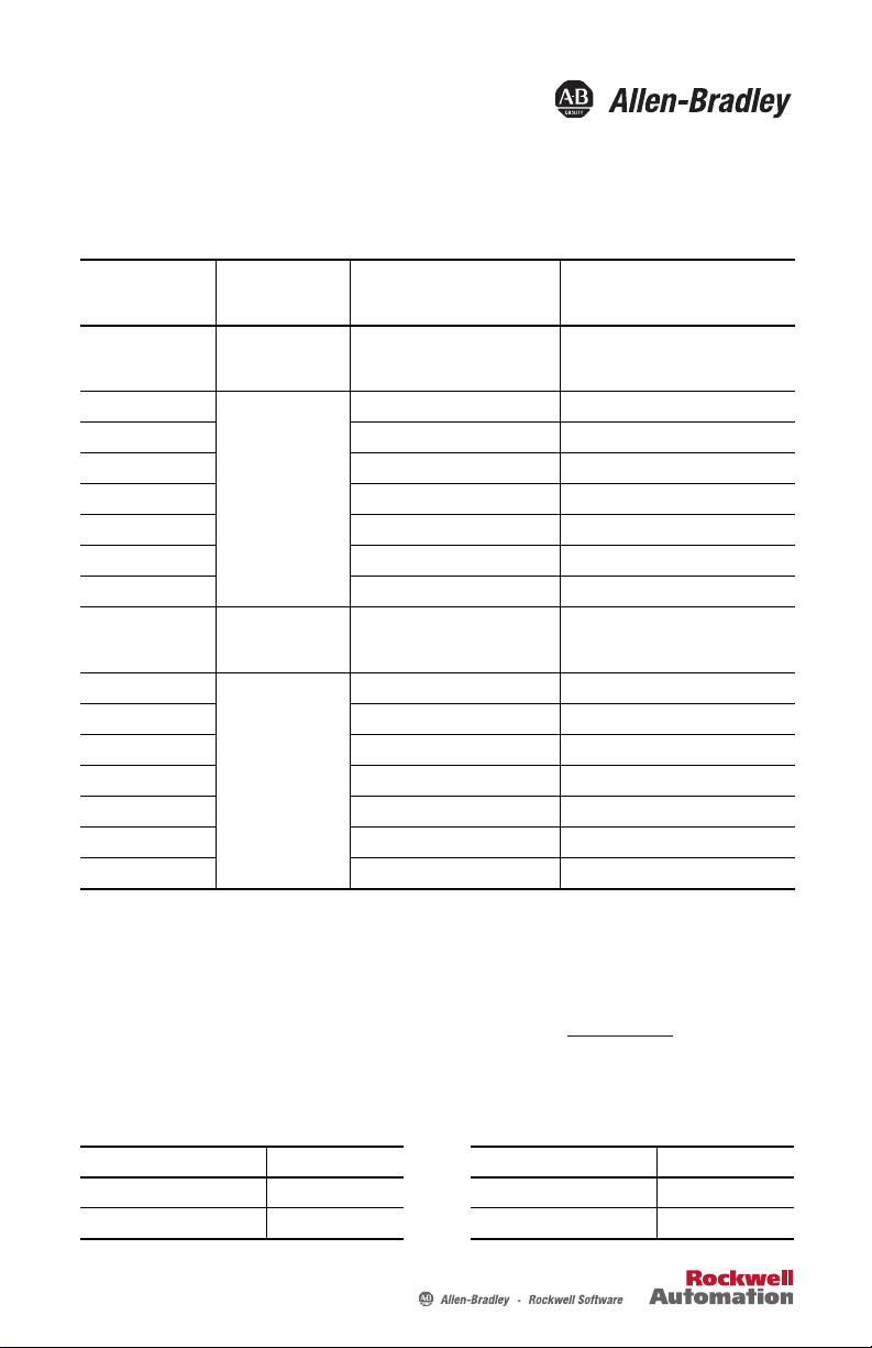
Catalog Numbers
Shared-bus
Connector Kits
Cat. No.
2198-H040-ADP-IN Frame 1 or 2 First drive
2198-H040-A-T
2198-H040-D-T DC sharing only DC bus T-connector
2198-H040-P-T Control power sharing only Control power T-connector
2198-H040-AD-T AC and DC bus sharing AC and DC bus T-connectors
2198-H040-AP-T AC and control power sharing AC and control power T-connectors
2198-H040-DP-T DC and control power sharing DC and control power T-connectors
2198-H040-ADP-T AC, DC, and control power sharing AC, DC, and control power T-connectors
2198-H070-ADP-IN
2198-H070-A-T
2198-H070-D-T DC sharing only DC bus T-connector
2198-H070-P-T Control power sharing only Control power T-connector
2198-H070-AD-T AC and DC bus sharing AC and DC bus T-connectors
2198-H070-AP-T AC and control power sharing AC and control power T-connectors
2198-H070-DP-T DC and control power sharing DC and control power T-connectors
2198-H070-ADP-T AC, DC, and control power sharing AC, DC, and control power T-connectors
Kinetix 5500 Drive
Frame Size and
Cat. No.
Next drive is…
Frame 1 drives:
• 2198-H003-xxx
• 2198-H008-xxx
Frame 2 drives:
• 2198-H015-xxx
• 2198-H025-xxx
• 2198-H040-xxx
Frame 3 drive:
2198-H070-xxx
Next drive is…
Frame 3 drives:
2198-H070-xxx
Application Description
• Mains AC input wiring connector
• 24V DC input wiring connector
• DC bus T-connector
AC sharing only AC bus T-connector
First drive
AC sharing only AC bus T-connector
• Mains AC input wiring connector
• 24V DC input wiring connector
• DC bus T-connector
About the Shared-bus Connector Kits
The Kinetix® 5500 shared-bus connection system is used to extend the mains AC input, 24V
control input, and DC bus power from drive-to-drive in shared-bus multi-axis configurations.
Refer to the Kinetix 5500 Servo Drives User Manual, publication 2198-UM001
information on wiring, applying power, troubleshooting, and integration with Logix5000™
controllers.
Power Ratings
Attribute Value Attribute Value
Input voltage, max 600V 24V control power current, max 32 A
AC input current, max 52 A Bus-bar current, max 70 A
, for detailed
Page 2
Rockwell Otomasyon Ticaret A.Ş., Kar Plaza İş Merkezi E Blok Kat:6 34752 İçerenköy, İstanbul, Tel: +90 (216) 5698400
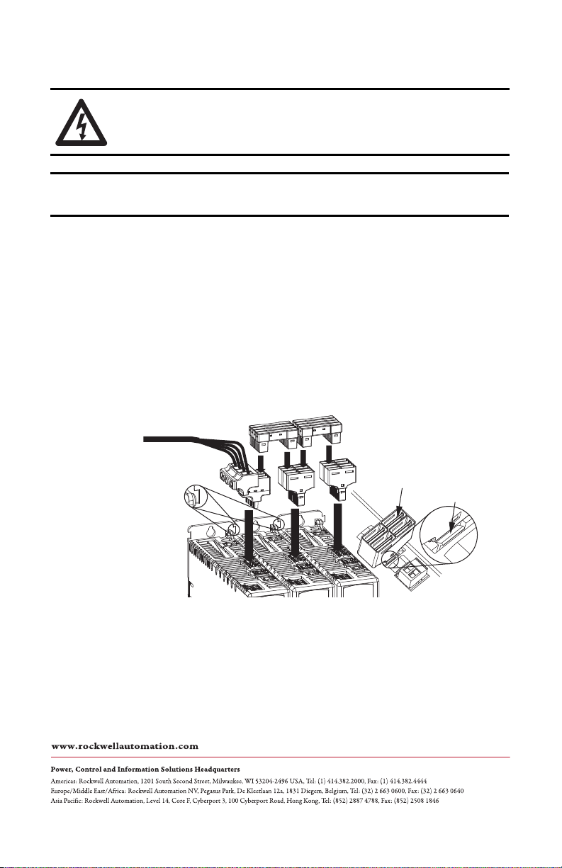
Install the Connector Kits
IMPORTANT
2198-Hxxx-xxx Drive System (top view)
Frame 2 drives are shown.
Drive with largest amp rating must be
leftmost drive.
Input Wiring Connector
(1)
AC T-connec tors
Bus-bar Connectors
(2)
(AC bus-bars shown)
Input Wiring
(AC input wiring is shown)
Zero-sta ck Tab
and Cutout Engaged
DC Bus Connector Latch
DC Bus T-connector
(3)
SHOCK HAZARD: To avoid hazard of electrical shock, perform all mounting and wiring of the
Kinetix 5500 drives and shared-bus connector kits prior to applying power. Once power is applied,
connector terminals can have voltage present even when not in use.
When the shared-bus connection system is used, the zero-stack tab and cutout must be
engaged between adjacent drives.
The connection system is comprised of three components:
• Input wiring connectors that plug into the leftmost drive and receive input wiring for
mains AC and 24V DC.
• AC bus, DC bus, and 24V DC T-connectors that plug into the drives downstream from
the first drive where AC, DC, and/or 24V control power is shared. DC bus
T-connectors also plug into the first drive where DC bus power is shared.
• Bus bars that connect between drives to extend the mains AC bus, DC bus, and 24V DC
control power from drive-to-drive.
This example illustrates the mains AC input wiring connector, T-connectors, and bus-bar
connectors. The 24V bus and DC bus systems connect in a similar way.
(1) D ue to the higher amp rating of frame 3 drives, input wiring connectors for frame 3 drives (catalog number 2198-H070-ADP-IN) are slightly larger
than connectors for frame 1 and 2 drives (catalog number 2198-H040-ADP-IN).
(2) D ue to the extra width of frame 3 drives, bus-bar connectors between frame 3 drives are slightly longer (85 mm) than connector s between frame 2
and frame 1 drives (55 mm).
(3) DC bus T-connectors latch on both sides whe n inserted into the drive. To remove the DC bus T-connector, at least one latch must be pried away with
a non-conductive probe.
Allen-Bradley, Kinetix, Logix5000, Rockwell Soft ware, and Rockwell Automation are trademarks of Rockwell Automation, Inc.
Trademarks not belonging to Rockwell Automation are property of their respective companies.
Publication 2198-IN005B-EN-P - August 2013
Copyright © 2013 Rockwell Automation, Inc. All rights reserved. Printed in the U.S.A.
 Loading...