

Page 1
Installation instruction
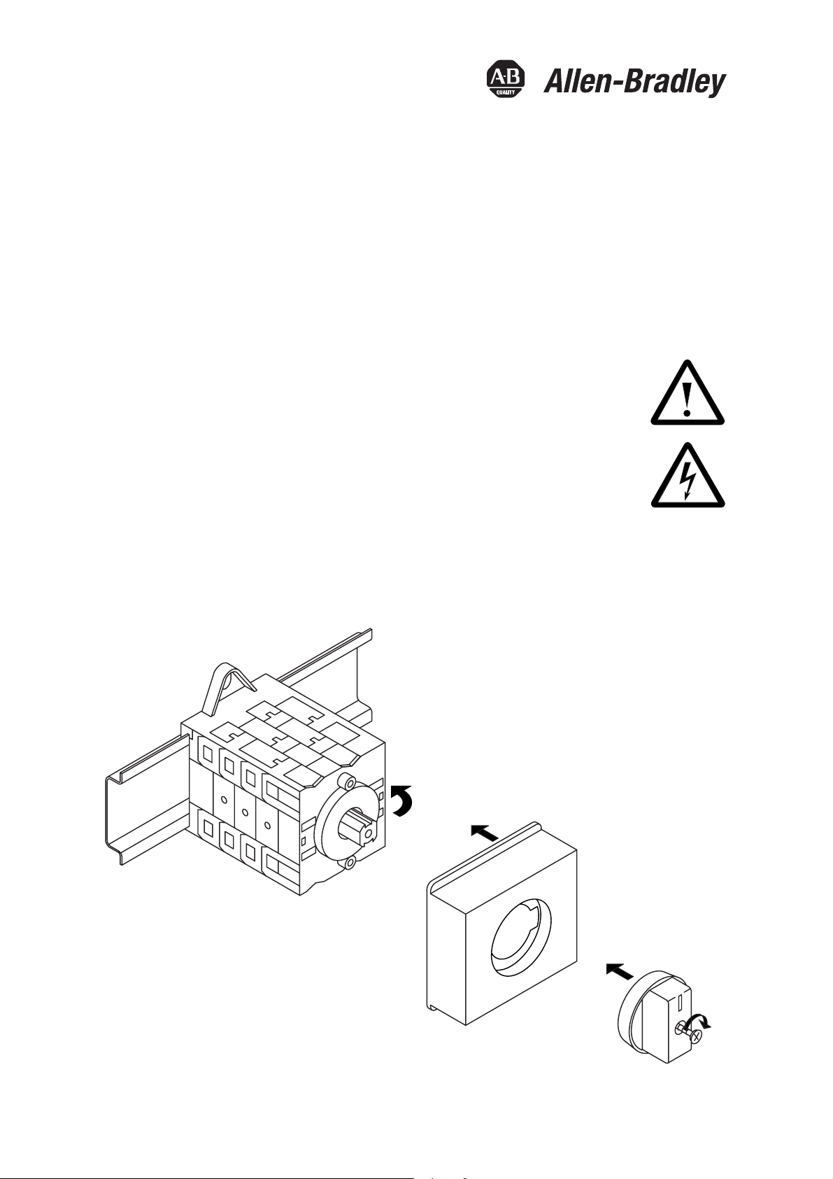
Attention: To prevent electrical shock, disconnect from
power source before installing or servicing.
Montageanleitung
Achtung: Vor Installations- oder Servicearbeiten Stromver-
sorgung unterbrechen, um Unfälle zu vermeiden.
Instruction de montage
Attention: Avant le montage et la mise en service, couper
l'alimentation secteur afin d’éviter tout accident.
Istruzione per il montaggio
Attenzione: Per prevenire infortuni, togliere tensione prima
dell'installazione o manutenzione
.
Instruccion de montaje
Atención: Desconectar la alimentación eléctrica antes de
realizar el montaje y la puesta en servicio, con el objeto
de evitar accidentes.
194L-A12(16)-...-Q
Bulletin
194L
1
2
S
0
R
T
S
TR
0
3
4
Page 2
IEC
Type
194L-12
194L-16
Type
194L-12
194L-16
AC-2
AC-22A
660 V
12 A
660 V
16 A
General
Use
12 A
600 Vac
16 A
600 Vac
IEC, VDE, BS
Ui660 V
Ui660 V
Motor starting
V
120
240
kW
V
kW
1
120
1.5
2
240
3
UL / CSA
480
5
480
7.5
V~
kW
V~
kW
600
5
600
7.5
AC-3
220
2.2
220
3
3ph
3ph
380
500
4
5.5
380
500
5.5
7.5
Max.
fuse
These devices
are suitable of
*
delivering not more
than 5000 rms
25 A
symetrical
amperes.600 V
max.when protected by a * K5 class
*
fuse.
30 A
Use Cu wire
60/75Þ C only
CEE 24
12 (8) A
500 Vac
16 (10) A
500 Vac
Torque
9Ib-in
1Nm
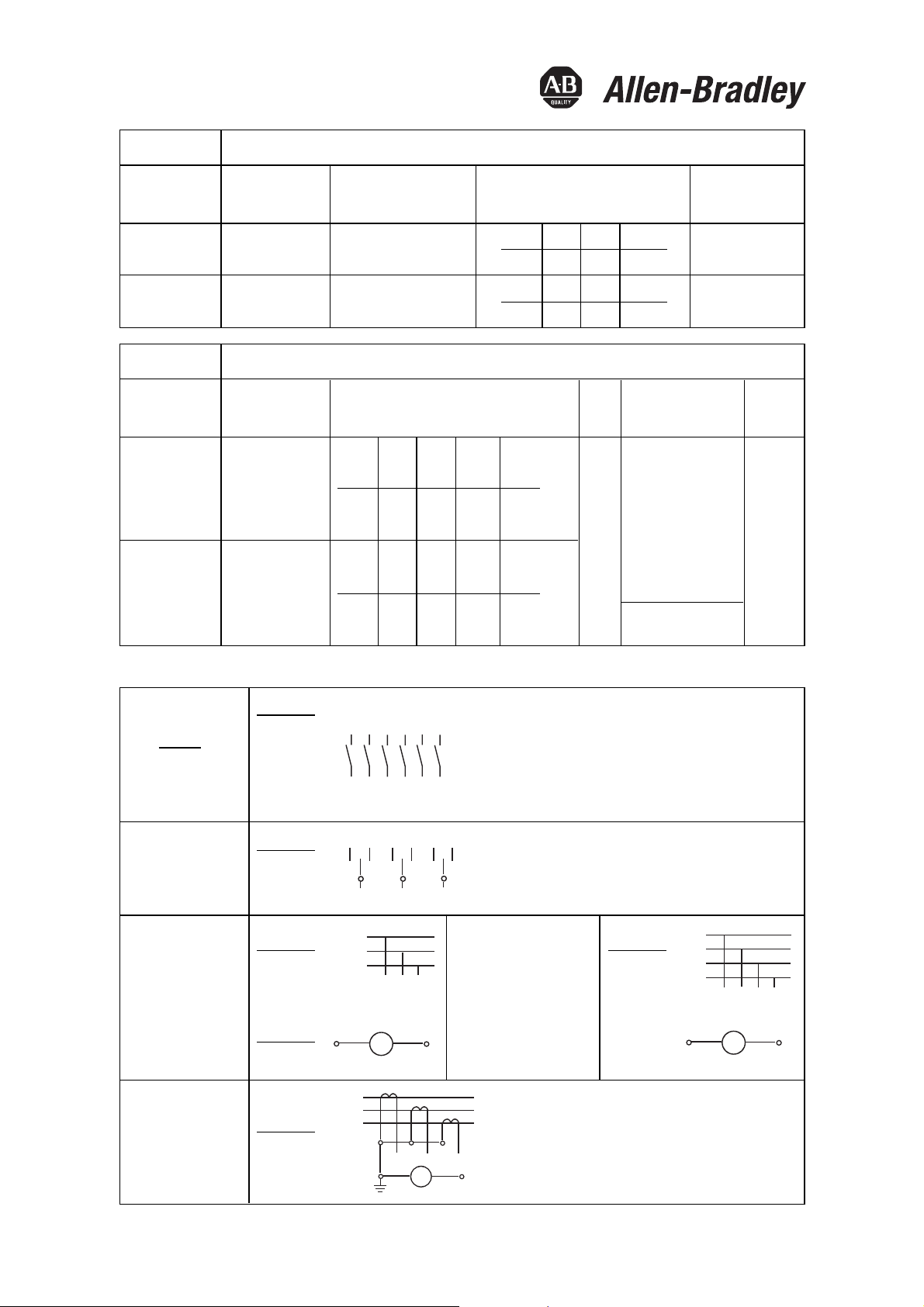
Anschlussplan - Wrings diagrams - Schema des connexions - Schemi di collegamento - Esquema de conexiónes
90°
ON-OFF
0-1
OFF-ON
Changeover
with 0
V-Meter-Switch
0-RS-ST-TR-0
0-RS-ST-TR
V-Meter-Switch
0-1-2-3
(3 Curr. Trans.)
1751
1752
1753
1754
1755
1756
45°
3251
3252
3253
45°
8271
45°
8271
90°
8751
1
2
R/L1
S/L2
T/L3
6
U/T1 V/T2
R/L1
S/L2
T/L3
345
1
V
6
6
7
6
5
7911
81012
53
11 9
10
73
2
95
A
4
V-Meter-Switch
L3 L2 L1 L1 L2 L3
---0- - -
L1 L3 L2 N N N
TR-ST-RS-0-RN-SN-TN
3
5
45°
8271
N/0
R/L1
S/L2
T/L3
5
39
10
U/T1 V/T2
1
12
V
Technical changes reserved
14.329.357-01 / 07. 2001
Edition 1
 Loading...