

Page 1
Data Highway Plus/DH485 Communication Adapter Module
(Cat. No. 1785KA5/B, KA5P/B)
User Manual
Page 2
Important User Information
Because of the variety of uses for the products described in this
publication, those responsible for the application and use of this control
equipment must satisfy themselves that all necessary steps have been taken
to assure that each application and use meets all performance and safety
requirements, including any applicable laws, regulations, codes and
standards.
The illustrations, charts, sample programs and layout examples shown in
this guide are intended solely for example. Since there are many variables
and requirements associated with any particular installation, Allen-Bradley
does not assume responsibility or liability (to include intellectual property
liability) for actual use based upon the examples shown in this publication.
Allen-Bradley publication SGI–1.1, “Safety Guidelines For The
Application, Installation and Maintenance of Solid State Control”
(available from your local Allen-Bradley office) describes some important
differences between solid-state equipment and electromechanical devices
which should be taken into consideration when applying products such as
those described in this publication.
Reproduction of the contents of this copyrighted publication, in whole or
in part, without written permission of Allen–Bradley Company, Inc. is
prohibited.
Throughout this manual we make notes to alert you to possible injury to
people or damage to equipment under specific circumstances.
ATTENTION: Identifies information about practices or
circumstances that can lead to personal injury or death, property
damage or economic loss.
Attention helps you:
- Identify a hazard
- Avoid the hazard
- recognize the consequences
Important: Identifies information that is critical for successful application
and understanding of the product.
Important: We recommend you frequently backup your application
programs on appropriate storage medium to avoid possible data loss.
1995 AllenBradley Company, Inc.
IBM
is a registered trademark of International Business Machines Corporation
PLC, PLC2, PLC3 and PLC5 are registered trademarks of AllenBradley Co. Inc.
DH+,
DHII,
PLC5/10, PLC5/12, PLC5/15, PLC5/25, PLC5/30, PLC5/40, PLC5/60, PLC5/250, SLC, SLC 5/01, SLC 5/02, SLC 5/03
and
SLC 500 are trademarks of AllenBradley Co., Inc.
Page 3

Summary of Changes
Summary of Changes
Summary of Changes
This publication contains new information not included in the last release.
New Information
European Union Directive Compliance
Information on the European Union Directive is located on pages 2-1
and A-1.
Auto Routing Feature
Detailed information on using the Auto Routing Feature is located on
pages 2-4 and 2-5.
Power Supply Requirements
Detailed information on power supply requirements for the European
Union Directive is located on page 2-13.
Change Bars
The areas in this manual which are different from the previous edition are
marked with change bars (as shown to the right of this paragraph) to
indicate the addition of new or revised information.
P-1
Page 4

Table of Contents
Using this Manual
Purpose
Who Should Read this Manual
Frequently Used Terms
Related
Updated
of this Manual
Publications
Information
. . . . . . . . . . . . . . . . . . . . . . . . . . . . . . .
. . . . . . . . . . . . . . . . . . . . . . . . . . . . . . . .
. . . . . . . . . . . . . . . . . . . . . . . . . .
. . . . . . . . . . . . . . . . . . . . . . . . . . . . . . .
. . . . . . . . . . . . . . . . . . . . . . . . . . . . . . . . . .
. . . . . . . . . . . . . . . . . . . . . . . . . . . . . . . . . .
Summary of Changes P1. . . . . . . . . . . . . . . . . . . . . . . . . . . .
Overview of the 1785KA5
Communication Adapter Module 11. . . . . . . . . . . . . . . .
What this Chapter Contains 11. . . . . . . . . . . . . . . . . . . . . . . . . . . .
What is the 1785KA5 Communication Adapter Module? 11
DH+ and DH485 Networks 12
The DH485 Network 14
Compatible Products 15
. . . . . . . . . . . . . . . . . . . . . . . . . . . . .
. . . . . . . . . . . . . . . . . . . . . . . . . . . . . . . . . .
. . . . . . . . . . . . . . . . . . . . . . . . . . . . . . . . .
. . . . . . . .
Installing the 1785KA5
Communication Adapter Module 21. . . . . . . . . . . . . . . .
What this Chapter Contains 21. . . . . . . . . . . . . . . . . . . . . . . . . . . .
European Union Directive Compliance 21
the Switches
Setting
Mounting the 1785KA5 Communication Adapter Module
in an I/O Rack
Panelmounting the 1785KA5 Communication Adapter Module 29
Connecting the 1785KA5 Module 210
Powering Up the 1785KA5 Module 216
. . . . . . . . . . . . . . . . . . .
22. . . . . . . . . . . . . . . . . . . . . . . . . . . . . . . . . .
28. . . . . . . . . . . . . . . . . . . . . . . . . . . . . . . . . . . .
. . .
. . . . . . . . . . . . . . . . . . . . . . . .
. . . . . . . . . . . . . . . . . . . . . . .
ii
ii
i
i
i
i
Communicating through the 1785KA5
Communication Adapter Module 31. . . . . . . . . . . . . . . .
What this Chapter Contains 31. . . . . . . . . . . . . . . . . . . . . . . . . . . .
Internet Protocol Addressing 31
1785KA5 Router Communication 34
1785KA5
PLC5
Controlling
Gateway Communication
to SLC Communication
the Flow of Data
. . . . . . . . . . . . . . . . . . . . . . . . . . . .
. . . . . . . . . . . . . . . . . . . . . . . .
36. . . . . . . . . . . . . . . . . . . . . .
38. . . . . . . . . . . . . . . . . . . . . . . . . . .
317. . . . . . . . . . . . . . . . . . . . . . . . . . . .
Specifications A1. . . . . . . . . . . . . . . . . . . . . . . . . . . . . . . . . .
Page 5
Using this Manual
Preface
Purpose
of this Manual
Who Should Read this
Manual
Frequently Used Terms
This manual describes the 1785-KA5 Data Highway Plus/DH485
communication adapter module. It contains information for:
installing and troubleshooting the module
using the module
We assume that you are already familiar with:
Allen-Bradley PLC and SLC processors
Allen-Bradley DH485 and Data Highway Plus
In this manual, we use the following terms:
This term Means
1785KA5 module,
or 1785KA5
DH+ Data Highway Plus
DH485 DH485 Data Highway
link a physical network
PLC programmable logic controller
SLC small logic controller
station (or node) the interface point at which devices, such as programmable
1785KA5 Data Highway Plus/DH485 communication adapter module
controllers, connect to the network. Usually the station is an interface
module, except for the PLC5
directly to the Data Highway Plus
and T50 terminal, which connect
i
Page 6

Preface
Using this Manual
Related
Publications
Updated Information
These Allen-Bradley publications contain related information:
Publicaton Publication Number
SLC 500 Overview brochure 17461.1
Bulletin 1746/47 SLC 500 Modular Hardware Style
Programmable Controllers I/O manual
Hand Held Terminal user's manual 1747809
Programming Terminals (Cat. Nos. 1784T45, T47, T50)
product data
DH+ LAN product data 17852.6
PLC5 Family Processor product data 17852.1
DH/DH+/DH485 Protocol and Command Set reference
manual
1747804
17842.1
17706.5.16
Also see the Advanced Programming Software (APS) user’s manual
(Cat. No. 1747-NM002 Series A.)
Since the last release of this manual, some information has changed. We
call your attention to the new information with a black revision bar in the
margin as shown here.
ii
Page 7

Chapter
1
Overview of the 1785KA5
Communication Adapter Module
What this Chapter Contains
What is the 1785KA5
Communication Adapter
Module?
Read this chapter for information on:
what the 1785-KA5 communication adapter module is
what DH+ and DH485 networks are
compatible products
The 1785-KA5 communication adapter module lets devices on the Data
Highway Plus (DH+) network communicate with devices on the RS-485
Data Highway (DH485) network for:
uploading/downloading of SLC 500 programs from a DH+ device
message communication between DH+ PLC processors and DH485
SLC 500 processors
The 1785-KA5 communication adapter module features:
concurrent operation as a gateway or router:
- in gateway mode, DH+ devices must initiate messages; DH485
devices cannot initiate messages
- in router mode, both DH+ and DH485 devices that implement
internet protocol (IP) can initiate messages (SLC 5/01, SLC 5/02,
and fixed controllers do not support IP)
support for existing IP
compatibility with other Allen-Bradley DH+ hardware and software
products
a baud rate of 57.6 Kbps on the DH+ network and 300bps-19.2 Kbps on
the DH485 network
1-1
Page 8

Chapter 1
Overview of the 1785KA5
Communication Adapter Module
DH+ and DH485 Networks
This section describes the DH+ and DH485 networks. For more
information on these networks, see the DH/DH+/DH485 Protocol and
Command Set reference manual (publication 1770-6.5.16).
DH+ Networks
DH+ is a baseband local area network (LAN) that allows peer-to-peer
communication among a maximum of 64 nodes. Each node has a unique
station address between 0–63 decimal and 0–77 octal. Use DH+ when you
want to connect a small number of nodes on a common link or with other
industrial networks as a part of a plant-wide CIM facility. DH+ features:
remote programming of PLC-2, PLC-3, and PLC-5 processors on your
network (using Allen-Bradley 6200 Series software)
direct connections to PLC-5 processors and industrial programming
terminals
easy reconfiguration and expansion if you want to add more nodes later
a communication rate of 57,600 bits per second
The DH+ implements peer-to-peer communication with a token-passing
scheme to rotate link mastership among its nodes. Since this method does
not require polling, it helps provide time-efficient reliable data transport.
The DH+ uses factory set timeouts to restart token-passing communication
if the token is lost because of a defective node.
1-2
Page 9
Chapter 1
Overview of the 1785KA5
Communication Adapter Module
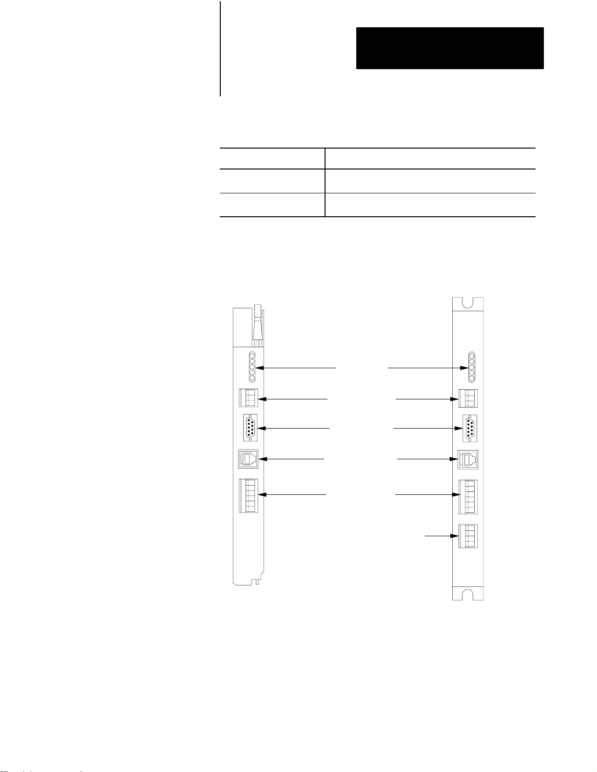
The 1785-KA5 communication adapter module is available in two
versions:
Use this version If your application is
1771 I/O rack mount
(Cat. No. 1785-KA5/B)
standalone panel mount
(Cat. No. 1785KA5P/A)
primarily DH+ with multiple 1771 I/O racks and SLC 500
subnetworks within close proximity
primarily a SLC (DH485) environment with no 1771 I/O racks in
close proximity
Figure 1.1 shows the module’s hardware features:
Figure 1.1
1785KA5
module
Status LEDs
DH+ connection
(3-pin Phoenix
connector)
DH+ remote
programming port
(9pin)
Dshell
programming
connection (8pin
modular connector)
DH485 connection
(6 - pin
Phoenix
connector)
1785-KA5/B I/O rack mount
External power (+ 5Vdc) connector
(4 -pin Phoenix connector)
1785-KA5P/B panel mount
19190
1-3
Page 10

Chapter 1
Overview of the 1785KA5
Communication Adapter Module
The DH485 Network
This section describes the DH485 network. For more information on this
network, see the DH/DH+/DH485 Protocol and Command Set reference
manual (publication 1770-6.5.16).
DH485 is a low cost, peer-to-peer programming and data acquisition link
for a variety of Allen-Bradley products, such as the SLC 500 family of
programmable controllers. A DH485 network provides a networking
solution for smaller applications (up to 32 nodes) within a small radius.
Each node has a unique station address between 0–31 decimal. The
maximum cable length is 4,000 feet. The DH485 link has a maximum
communication rate of 19,200 bits per second.
A DH485 network has a topology that is similar to that of a DH or DH+
network. DH485 is based on the EIA Standard RS-485 Electrical
Signalling Specification and implements token-passing protocol with
rotating mastership. The link protocol delimits messages, detects and
signals errors, retries after errors and controls message flow.
A variety of Allen-Bradley products, such as the SLC 500 family of
controllers, the SLC 500 APS programming software, the 1784-KTX,
-KTXD and -KR modules, and the 1770-KF3 module act as token-passing
masters on the DH485 network. The DH485 protocol also supports slave
(respond-only) mode for low-level devices on the network.
The 1784-KTX, -KTXD and -KR modules provide an IBM PC backplane
link to the DH485. It provides an asynchronous link to connect devices on
the network. An asynchronous device can interface with a DH485 module
directly or through a modem link.
1-4
Page 11
Chapter 1
Overview of the 1785KA5
Communication Adapter Module
Compatible Products
You can use the following Allen-Bradley products with the 1785-KA5
module:
This product Has this Cat. No.
DH+ PLC2 Communication Module 1785KA3
Processor Communication Interface Module
(for IBM PC/XT/AT)
Processor Communication Interface Module
(for IBM PS/2)
Communication Interface Module for the 1784T47
Programming Terminal
I/O ScannerCommunication Adapter Module 1775S5
DH+ PLC3 Communication Module 1775S5, SR5
SLC 500 Hand Held terminal 1747PT1 (with 1747PTA1E
Portable Programming Terminal 1784T45, T47
Advanced Programming Software 1747PA2E (series x and up)
Standard Driver Software 6001F1E, F1E2
6001NET (for VAX) Network Communication Software 6001A1D, G1D, A1DB, G1DB
1784KT
1784KT2
1784KL
firmware)
The following Allen-Bradley PLC and SLC processors are compatible with
the 1785-KA5 module:
PLC-5/10
PLC-5/12
PLC-5/15
PLC-5/25
PLC-5/30
PLC-5/250
PLC-5/40
PLC-5/60
SLC 5/03
SLC 5/04
SLC 500 (can only reply to remote messages)
SLC 5/01 (can only reply to remote messages)
SLC 5/02 (can only reply to remote messages)
1-5
Page 12

Chapter
2
Installing the 1785KA5
Communication Adapter Module
What this Chapter Contains
European Union Directive Compliance
This chapter explains how to install the 1785-KA5 module in a 1771 I/O
rack or in a stand-alone panel mount setup. It contains the following
sections:
the European Union Directive Compliance
setting the switches
installing the 1785-KA5 module in an I/O rack
installing the 1785-KA5 panel-mount version
connecting the module
powering up
If this product is installed within the European Union or EEA regions and
has the CE mark, the following regulations apply.
EMC Directive
This apparatus is tested to meet Council Directive 89/336/EEC
Electromagnetic Compatibility (EMC) using a technical construction file
and the following standards, in whole or in part:
EN 50081-2 EMC – Generic Emission Standard, Part 2 – Industrial
Environment
EN 50082-2 EMC – Generic Immunity Standard, Part 2 – Industrial
Environment
The product described in this manual is intended for use in an industrial
environment.
Low Voltage Directive
This apparatus is also designed to meet Council Directive 73/23/EEC
Low Voltage, by applying the safety requirements of EN 61131–2
Programmable Controllers, Part 2 – Equipment Requirements and Tests.
For specific information that the above norm requires, see the appropriate
sections in this manual, as well as the following Allen-Bradley publications:
Industrial Automation Wiring and Grounding Guidelines, publication
1770-4.1
Guidelines for Handling Lithium Batteries, publication AG-5.4
Automation Systems Catalog, publication B111
2-1
Page 13
Chapter 2
Installing the 1785KA5
Communication Adapter Module
Setting the Switches
The 1785-KA5 module has three banks of DIP switches that let you select
various communication options. The switch assemblies and their
corresponding options are:
To set the Use switch assembly
DH485 station address and baud rate SW1
DH+ station address and the auto route enable option SW2
DH485 and DH+ channel LINK_IDs SW3
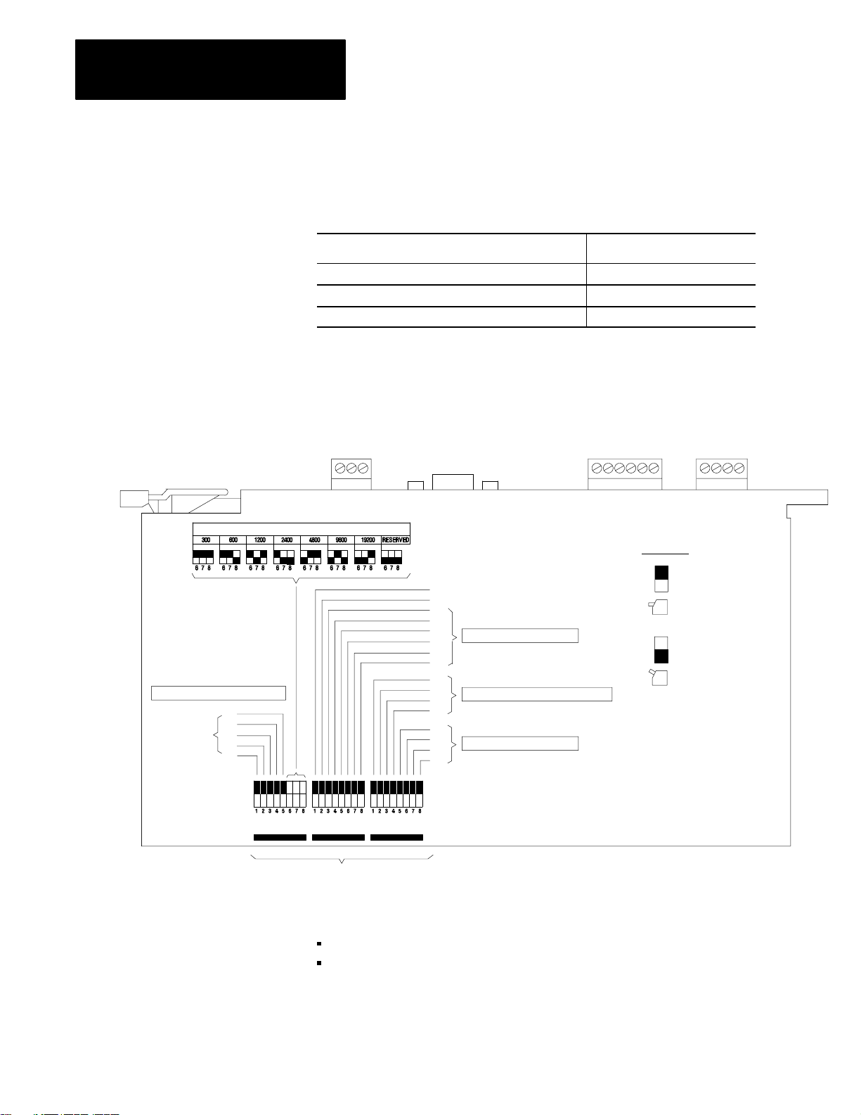
Figure 2.1 shows the location of the switches on the 1785-KA5 module.
Figure 2.1
1785KA5
1785KA5/B shown)
DH485 BAUD RA
communication adapter module switch assemblies (cat. no.
TE
LEGEND
DH485 STATION ADDRESS
B0
B1
B2
B3
B4
ON
OFF
SW - 1 SW - 2
switch assemblies
Important: The 1785-KA5 uses the following convention:
on = binary 1
off = binary 0
SW - 3
B7
RESERVED
B6
AUTO ROUTE ENABLE
B5
B4
B3
DH+ STA
B2
B1
B0
B3
B2
B1
B0
B3
B2
B1
B0
TION ADDRESS
DH485 CHANNEL DH+ IP LINK ID
DH+ CHANNEL LINK ID
19191
OFF
ON
(0)
(1)
2-2
Page 14
Chapter 2
Installing the 1785KA5
Communication Adapter Module
SW1: DH485 Station Address and DH485 Baud Rate
Use switch assembly SW-1 to select the DH485 station address and baud
rate for the 1785-KA5 module. The following sections show you how.
Setting the DH485 Station Address
Set switches 1-5 of SW-1 to the DH485 station address for the 1785-KA5.
Valid addresses are 0-31 decimal or 0-37 octal. Set the switches as
follows:
Most significant octal digit (switches 12)
To set to Set switch 1 to Set switch 2 to
0 0 0
1 0 1
2 1 0
3 1 1
Least significant octal digit (switches 35)
To set to Set switch 3 to Set switch 4 to Set switch 5 to
0 0 0 0
1 0 0 1
2 0 1 0
3 0 1 1
4 1 0 0
5 1 0 1
6 1 1 0
7 1 1 1
For example
To set the module’s DH485 station address to 15 decimal or 17 octal, set
the SW-1 switches as follows:
Set switch To
1 0
2 1
3 1
4 1
5 1
most significant octal digit = 1
least significant octal digit = 7
2-3
Page 15
Chapter 2
Installing the 1785KA5
Communication Adapter Module
Setting the DH485 Baud Rate
Set switches 6-8 of SW-1 to the DH485 baud rate as follows:
To set this baud rate Set switch 6 to Set switch 7 to Set switch 8 to
300 0 0 0
600 0 0 1
1200 0 1 0
2400 0 1 1
4800 1 0 0
9600 1 0 1
19200 1 1 0
RESERVED 1 1 1
SW2: Auto Routing and DH+ Station Address
The module has an auto routing feature that broadcasts an information
packet over the Data Highway network every 30 seconds.
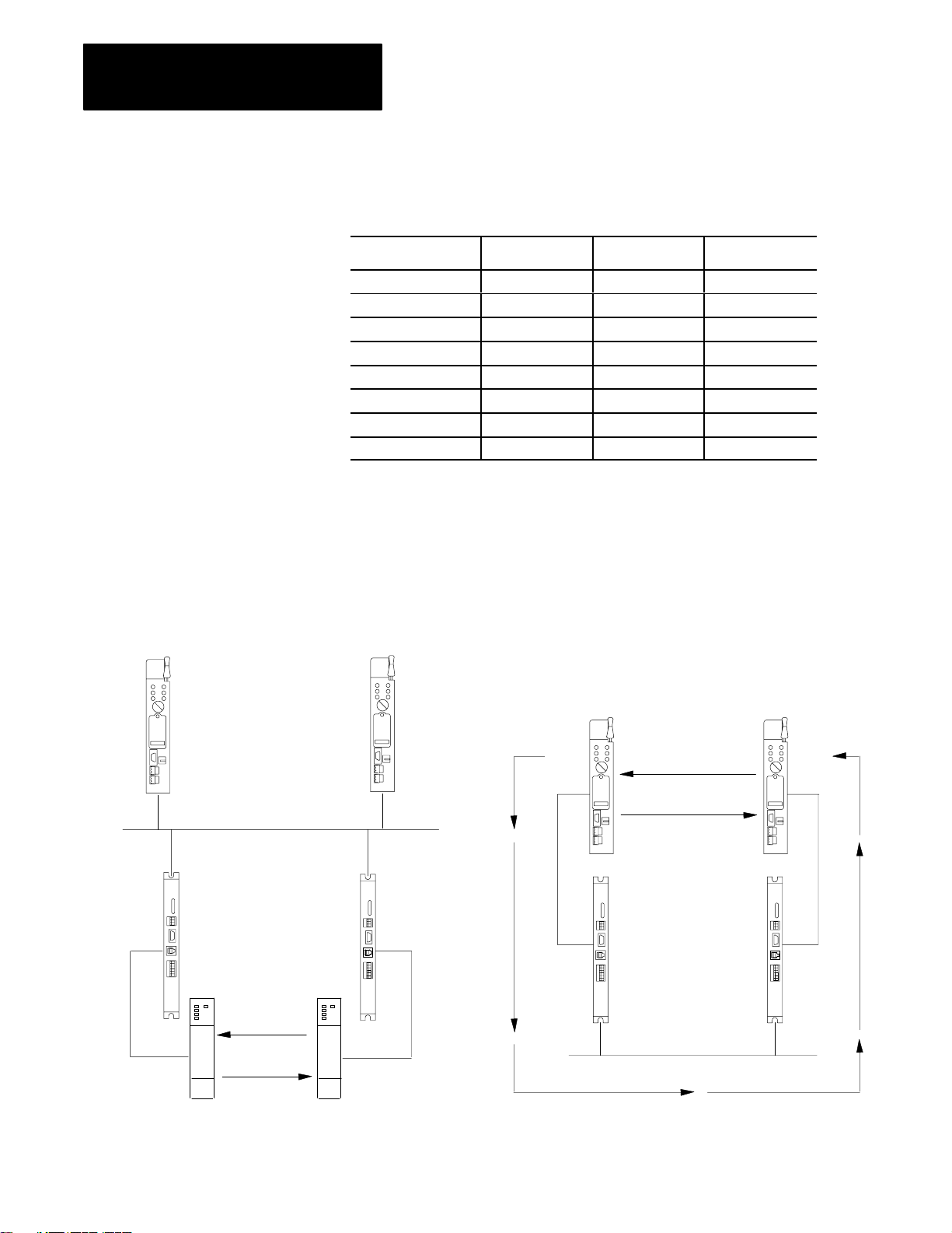
The following illustration shows the only two network configurations
that you must use auto routing with:
PLC5 PLC5
Data Highway Plus
1785KA51785KA5
DH+
PLC5
PLC5
Desired
Communication
DH+
DH485
2-4
SLC5/03
Desired
Communication
SLC5/03
DH485
1785KA5
1785KA5
DH485
Page 16

Chapter 2
Installing the 1785KA5
Communication Adapter Module
If you are not using one of these two network configurations, do not use
the auto routing feature.
If you: Then:
do not plan to use the auto routing feature skip to the next section, How to Enable or
Disable the Module for Auto Routing to
learn how to disable the auto routing
feature
plan to use the auto routing feature continue with this section to determine if
you can use the auto routing feature in
your network
ATTENTION: Do not use auto routing in a network that
includes any of the following components:
1785-KE module
6008-LTV module
1785-KA module
1785-KA3 module
1775-S5 module
1784-KT card
1784-KTX card
1784-KTXD card
Module and system faults occur when you use auto routing in a system that
includes any of these network components. Be sure to disable the auto
routing feature when using these components.
How to Enable or Disable the Module for Auto Routing
Use switch assembly SW-2 to enable or disable the module for auto
routing.
To: Set switch 2 to
enable auto routing 1
disable auto routing 0
Important: Switch 1 of SW-2 is reserved. Always set this switch to (0).
2-5
Page 17

Chapter 2
Installing the 1785KA5
Communication Adapter Module
Setting the DH+ Station Address
Set switches 3-8 of SW-2 to the DH+ station address for the 1785-KA5.
Valid addresses are 0-77 octal Set the switches as follows:
Most significant octal digit (switches 35)
To set to Set switch 3 to Set switch 4 to Set switch 5 to
0 0 0 0
1 0 0 1
2 0 1 0
3 0 1 1
4 1 0 0
5 1 0 1
6 1 1 0
7 1 1 1
Least significant octal digit (switches 68)
To set to Set switch 6 to Set switch 7 to Set switch 8 to
0 0 0 0
1 0 0 1
2 0 1 0
3 0 1 1
4 1 0 0
5 1 0 1
6 1 1 0
7 1 1 1
For example
To set the module’s DH+ station address to 64 octal, set the switches as
shown below:
Set switch To
3 1
4 1
5 0
6 1
7 0
8 0
most significant octal digit = 6
least significant octal digit = 4
2-6
Page 18

Chapter 2
Installing the 1785KA5
Communication Adapter Module
SW3: DH485 Channel LINK_ID and DH+ Channel LINK_ID
The 1785-KA5 module has two LINK_ID addresses: one for its DH485
side and one for its DH+ side. See the following table to set switches 1-8
of SW-3.
Important: Do not use a LINK_ID of 0 (zero). This address is reserved. If
you have more than one 1785-KA5 module on a single physical network,
the LINK_IDs for the two modules must be the same.
To set the DH485
LINK_ID to
To set the DH+
LINK_ID to
1 0 0 0 1
2 0 0 1 0
3 0 0 1 1
4 0 1 0 0
5 0 1 0 1
6 0 1 1 0
7 0 1 1 1
8 1 0 0 0
9 1 0 0 1
10 1 0 1 0
11 1 0 1 1
12 1 1 0 0
13 1 1 0 1
14 1 1 1 0
15 1 1 1 1
Set switch 1 to Set switch 2 to Set switch 3 to Set switch 4 to
Set switch 5 to Set switch 6 to Set switch 7 to Set switch 8 to
For example
To set the module’s DH485 LINK_ID to 4 and DH+ LINK_ID to 8, set the
switches as follows:
Set switch To
1 0
2 1
3 0
4 0
5 1
6 0
7 0
8 0
DH485 LINK_ID = 4
DH+ LINK_ID = 8
2-7
Page 19

Chapter 2
Installing the 1785KA5
Communication Adapter Module
Important: Each physical network link must have a unique LINK_ID
address.
The next section shows you how to mount the module in a 1771 I/O rack.
See page 2-9 for instructions on mounting the stand-alone version.
Mounting the 1785KA5
Communication Adapter
Module in an I/O Rack
The 1785-KA5 mounts in any slot of an Allen-Bradley 1771 bulletin I/O
rack, except slot zero. If you are using a dropline/trunkline configuration,
mount the 1785-KA5 module within 10-100 feet of the DH+ trunkline. The
maximum cable length for DH485 trunk connections is 4,000 ft., with
individual stations “daisy-chained” together.
To install the 1785-KA5 module in a 1771 bulletin I/O rack:
1. Perform an orderly power down of the rack and its controlling PLC
processor.
ATTENTION: Remove system power before removing or
installing the module in the 1771 I/O chassis. Failure to observe
this warning could result in:
damage to the module’s circuitry
undesired operation and possible injury to personnel
2. Insert the optional keying bands provided with the 1771 I/O rack on
the backplane (The 1785-KA5 is keyed to protect against installing it
in the wrong I/O rack slot). Insert one band between keying positions
6 and 8. Insert the other between positions 12 and 14. The figure
below shows the keying positions:
2-8
Keying
Bands
19193
Page 20

Chapter 2
Installing the 1785KA5
Communication Adapter Module
3. Slide the 1785-KA5 module into one of the slots in the 1771 I/O rack.
Make sure the module is seated properly. Snap down the latch on the
top of the module to secure proper placement in the rack (You can
change the position of the keying bands if subsequent system design
requires the insertion of a different type of module in this slot).
Now you are ready to connect the module (see page 2-10.)
Panelmounting the
1785KA5 Communication
Adapter Module
The rear edge of the 1785-KA5 panel-mount version contains a mounting
bracket that lets you install the module. If you are using a
dropline/trunkline configuration, mount the 1785-KA5 panel-mount
module within 10-100 feet of the DH+ trunkline. Figure 2.2 shows the
mounting dimensions for the module.
Figure 2.2
1785KA5
288mm
(11.35")
panelmount module (Cat. No. 1785KA5P/B) dimensions
149mm
(5.87")
305mm
(12.0")
39mm
(1.53")
hole size
accommodates
up to 1/4 - 20
size screw
19194
To protect the module from harmful environmental conditions, enclose it in
a standard industrial enclosure (NEMA type 12 or equivalent.)
2-9
Page 21

Chapter 2
Installing the 1785KA5
Communication Adapter Module
Important: Make sure the enclosure leaves a 6 inch (minimum) clearance
at the top and bottom of the module for air flow.
After you mount the module, you are ready to make connections.
Connecting the 1785KA5
Module
Figure 2.3 shows the ports on the front panel of the 1785-KA5 module:
Figure 2.3
1785KA5
connectors
DH+
DH+
Programming
Terminal
AUX
(for
programmer)
DH485
2-10
Cat. No. 1785KA5/A
rackmount module
Power Supply
Cat. No. 1785KA5P/A
panelmount module
19195
Page 22

Chapter 2
Installing the 1785KA5
Communication Adapter Module
To connect the 1785-KA5 module:
1. Use the 3-pin port labeled Data Hwy Plus to connect the DH+
dropline (100 ft. max.) or the daisy-chained cable to the 1785-KA5
module. Connect the Allen-Bradley cable (cat. no. 1770-CD) to the
3-pin plug as shown:
1770CD
Cable
Blue (2)
Shield (SH)
Clear (1)
20224
2. Use the 9-pin D-shell port labeled Data Hwy Plus to connect your
programming terminal (such as the 1784-T50 programming terminal
used with a 1784-CP cable) to the DH+ network:
Pin Signal
1 (clear) signal wire
5 (blue) signal wire
7 (bare) cable shield wire
2-11
Page 23

Chapter 2
Installing the 1785KA5
Communication Adapter Module
3. Use the 8-pin modular port labeled AUX to connect the SLC 500
programmer. Use an Allen-Bradley cable (cat. no. 1747-C10
series A):
Pin Signal
1 data
2 -data (B)
3 (not used)
4 24v enable (internally connected to ground
5 TXEN (from HHT)
6 earth ground (chassis)
7 signal ground
8 +24V dc @ 105 ma
(A)
pin 7)
4. Use the 6-pin terminal block labeled DH485 to connect to the DH485
dropline. Use Belden #9842 cable:
Pin Signal
1 earth ground (chassis)
2 cable shield
3 signal ground/common
4 data (B)
5 -data (A)
6 termination
2-12
Colors for the Belden #9842 cable are shown below:
earth ground
drain cable shield
blue/whitestripe
white/orangestrip data(B)
orange/whitestripe -data(A)
termination
1
2
3
4
5
6
a. Cut the white wire with the blue stripes from the twisted
wire pair. Do not use this wire.
b. Connect only one end of the trunk cable to earth ground
(chassis) by jumpering pins 1 and 2 together on the connector.
Page 24

Chapter 2
Installing the 1785KA5
Communication Adapter Module
Important: If the 1785-KA5 module is attached at either end of the
DH485 network trunk cable, install a wire jumper between pins 4 and 6 of
the 6-pin mating connector supplied with the module. This is the
termination resistor for the network.
5. If you are connecting a 1785-KA5P/B panel-mount module, you need
to connect the external power supply:
Important: To meet the Low Voltage Directive regulations within the
European Union or EEA Regions, you must use a Class 2 Safety Extra-low
Voltage power supply.
a. Wire a power supply cable as shown below:
5V dc
supply @
3 Amps
(CHASSIS GROUND) Green/Yellow
0V dc (dc GND) Black
+5V dc Red
14 AWG standard colorcoded wire
4pin Phoenixstyle connector
supplied with 1785KA5P/B module
4
3
2
1
(connect to power
connector on the
1785KA5P/B module)
(no connection)
The earth ground or chassis ground wire should be color-coded
green with a yellow stripe.
b. Wire the cable using the 4-pin connector you received with your
module and connect the cable to the EXT PWR connector on the
module.
Pin Signal
1 no connection
2 +5V dc @ 2.0 amps (red)
3 0Vdc (dc GND) black
4 (Chassis Ground) green/yellow
2-13
Page 25

Chapter 2
Installing the 1785KA5
Communication Adapter Module
The following figure shows how typical connections are made on the
DH485 link.
1785KA5
Gateway Module
Belden
#9842
DH485
Belden
#9842
DH485
Connector
Connector
1784KTX,
KTXD or
KR
Interface
Module
Connector
19196Link Coupler 1747AIC
2-14
Page 26

Chapter 2
Installing the 1785KA5
Communication Adapter Module
The figure below shows a typical system connection using the 1785-KA5
module:
PLC-5/15
1785-KA5 module
DH+
DH+ Remote
Terminal
AUX
DH485
SLC 500
controller
Connect DH485 stations at any point along the length of the cable using a
link coupler (cat. no. 1747-AIC) and daisy-chain connections.
Data Highway Plus
T70 Terminal
(with 1784KT,
KTX or KTXD)
DH485 daisy chain
1747-AIC
Link coupler
1747-C11 Cable
19197
2-15
Page 27

Chapter 2
Installing the 1785KA5
Communication Adapter Module
Powering Up the 1785KA5
Module
After you have:
set the switch assemblies on the 1785-KA5 module
mounted your 1785-KA5 module
connected the 1785-KA5 module to the DH+ and DH485 (and,
optionally, the 1784-T50 programming terminal, the SLC 500
programmer and the external power supply)
you are ready to power up the 1785-KA5 module. To power up the
module:
1. Perform a power up of the I/O rack and PLC processor (refer to your
PLC user’s manual for more information.)
At power-up, the 1785-KA5 performs internal memory and device
diagnostic checks. Both the DH+ and DH485 have duplicate address
protection. During these tests, the red FAULT LED lights up and the
top three green LEDs (DH+TX, DH+RX, DH485TX) sequence
through test values.
2. Use the LEDs to verify that the module was installed properly. The
diagnostic check is complete when the red FAULT LED turns off
(tests normally complete within 10 seconds.) The figure below shows
the LEDs.
2-16
DH+ transmit (green)
DH+ receive (green)
DH485 transmit (green)
DH485 receive (green)
CPU Fault (red)
DH+TX
DH+RX
DH485TX
DH485RX
FAULT
19198
Page 28

Chapter 2
Installing the 1785KA5
Communication Adapter Module
Use the following table to determine if the installation was
successful:
If the installation was Then
successful -only the green LEDs flash on and of
-the DIP switches are read. All DIP switches are read at this
time only. Changes you make after this time are ignored.
Important: Always power down the module before you change
DIP switch settings.
unsuccessful -the red LED remains on and the green LEDs freeze at the
failed value
-the 1785KA5 is removed from both the DH+ and DH485
networks. Originating devices can not send packets through
the module and do not receive responses.
f.
Use the module’s LEDs and the following table to interpret an
installation failure:
DH+TX DH+RX DH485TX Problem
off off on bad ROM checksum
off on off RAM address test failed
off on on RAM pattern test failed
on off off CTC timer tests failed
Important: If only the red FAULT LED lights up, there are two possible
causes:
a duplicate station address was detected on the DH+ or DH485
the KA5P is indicating that there is a problem with the external
power supply or cable
2-17
Page 29

Chapter
3
Communicating through the 1785KA5
Communication Adapter Module
What this Chapter Contains
Internet Protocol Addressing
This chapter includes information on:
network addressing
how the 1785-KA5 module operates as a router
how the 1785-KA5 module operates as a gateway
PLC-5 to SLC communication
controlling the flow of data
Each station on the internet must have a unique Internet Protocol (IP)
address to help a packet reach its intended receiver. The IP address is the
high level address used to send message packets back and forth across the
internet. The IP address must be unique over all physical networks that are
connected, not just one local network channel. It is needed because a
device on the DH+ network may have the same address as a device on the
DH485 network. The IP address has two parts:
LINK_ID address
DH+/DH485 STATION address
LINK_ID Address
The LINK_ID is the address of the link (individual cable or channel). Each
network link in the internet should have a unique LINK_ID address. You
set the LINK_ID address using the switches on the interface module for
each station.
Important: If more than one 1785-KA5 module is attached on one
physical link, each must have the same LINK_ID address.
3-1
Page 30

Chapter 3
Communicating through the 1785KA5
Communication Adapter Module
For example:
In Figure 3.1, the DH+ LINK_IDs for all three 1785-KA5 modules must
be set to 1 (the DH+ LINK_ID.)
Figure 3.1
addressing
IP
DH+ (LINK_ID = 1)
1785 -KA5
5
DH+ LINK_ID 1,
station 2
DH485 LINK_ID 2,
station 10
DH485 (LINK_ID = 2)
1785 -KA5
DH+ LINK_ID 1,
station 3
DH485 LINK_ID 3,
station 11
DH485 (LINK_ID = 4)
DH485 (LINK_ID = 3)
5
1785 -KA5
DH+ LINK_ID 1,
station 4
DH485 LINK_ID 4,
station 12
19199
Important: The following LINK_ID addresses are reserved:
This LINK_ID address Is reserved for the
LINK_ID = 0 local network. When a station does not know its own LINK_ID, it can
specify 0 until it determines the value (from a router, for example)
LINK_ID = FFFFh internet broadcast address. When using this address, the STATION
fields must also be all ones. The broadcast address is only permitted
in the destination field. The broadcast packet is routed to all internet
addresses
3-2
Page 31

Chapter 3
Communicating through the 1785KA5
Communication Adapter Module
DH+/DH485 STATION Address
The DH+ and DH485 address is the low level physical address that
identifies a device on a single physical network. Each physical device must
have a unique STATION address on that link. You set the STATION
address using the switches on the interface module. Valid physical
addresses are 0-77 octal for the DH+ network and 0-31 decimal for the
DH485 network.
Important: Each physical device on a link must have a unique address on
that link. Two devices can not have the same address.
For example:
Figure 3.1 on page 3-2 shows a DH+ network with a LINK_ID of 1
connected to a DH485 network with a LINK_ID of 2 by a 1785-KA5
module. Both networks have stations with addresses of 5, yet each device
has a unique IP address.
This device Has this IP address
device 3 on the DH+ network LINK_ID = 1, station = 3
device 3 on the DH485 network LINK_ID = 2, station = 3
3-3
Page 32

Chapter 3
Communicating through the 1785KA5
Communication Adapter Module
1785KA5 Router
Communication
This section explains:
router mode addressing
how the 1785-KA5 operates as a router
Router Mode Addressing
A DH+ device wishing to send an internet packet to a DH485 device must
set the internet destination address (LINK_ID, STATION) to the:
LINK_ID of the DH485 network
STATION address to the DH485 device
How the 1785KA5 Module Operates as a Router
The 1785-KA5 module operates as a router when attached DH485 stations
fully implement IP protocol (if they do not, it acts as a gateway) DH485
stations that implement IP can initiate commands, as well as send reply
messages.
Important: SLC 5/01, SLC 5/02 and fixed controllers do not support IP.
To communicate with one of these processors, use the 1785-KA5 module
as a gateway.
When the 1785-KA5 module receives an internet packet, it acts as an
intermediate station and passes the packet along in the correct direction.
Unlike the gateway process, no packet conversion is necessary because
stations on both sides of the 1785-KA5 “speak the same language.”
3-4
Page 33

Chapter 3
Communicating through the 1785KA5
Communication Adapter Module
The figure below demonstrates internet router mode communication from a
PLC-5 processor (on DH+) to another PLC-5 (on a remote DH+ network)
across the DH485. The auto route enable switch, switch 2 of SW-2 (see
page 2-2) is set to on (1) for both 1785-KA5 modules.
PLC5 PLC5
DH+LINK_ID1,
station10
DH+LINK_ID3,
station15
DH+
LINK_ID=1
DH+LINK_ID1,
station11
DH485 LINK_ID 2,
station 12
DH485LINK_ID=2
1785-KA5 1785-KA5
DH+
LINK_ID=3
DH+LINK_ID3,
station14
DH485 LINK_ID 2,
station 13
19235
The message instruction below (as shown in Allen-Bradley 6200 Series
software) shows the PLC-5 on the left writing 64 words from its data file
N20:0 to data file N21:0 of the remote PLC-5 on the right. The 1785-KA5
modules (in router mode) determine which device in the internet to route
the message, so if the internet contains multiple 1785-KA5 modules, the
message still reaches its intended destination.
Figure 3.2
Message
instruction
In this message transfer process:
the message is first sent to the
local node, which is the 1785KA5
module (DH+ LINK_ID = 1, STATION 11)
the 1785KA5 determines the
location of the remote station in the
internet and reroutes it to the proper
destination, which is the PLC5
(DH+LINK_ID = 3, STATION 15)
MESSAGE INSTRUCTION DATA ENTRY FOR CONTROL BLOCK N10:0
Communication command: PLC-5 typed write
PLC-5 data table address: N20:0
size in elements: 64
Local/Remote: Remote
Remote station: 15
LINK_ID: 3
Remote link type: DATA HIGHWAY
Local node address: 11
Destination data table address: N21:0
Block size = 11 words
3-5
Page 34

Chapter 3
Communicating through the 1785KA5
Communication Adapter Module
1785KA5
Gateway
Communication
This section explains:
gateway mode addressing
how the 1785-KA5 operates as a gateway
“single-hop” mode packets
Gateway Mode Addressing
All DH+ and DH485 destination and source addresses are contained in the
lower address byte, leaving the upper byte free for “sub-addressing.” An
internet device sends a packet to a non-internet device on the DH485 link
by:
addressing the lower byte of the STATION address (D_STATION[0]) to
the 1785-KA5 adapter module for packet processing
addressing the upper byte of the STATION address (D_STATION[1]) to
the actual destination device. The upper byte of the STATION field is
defined as follows:
3-6
Page 35

Chapter 3
Communicating through the 1785KA5
Communication Adapter Module
How the 1785KA5 Module Operates as a Gateway
The 1785-KA5 module operates as a gateway when attached DH485
stations do not fully implement IP. It converts IP packets to DH485 local
packets and sends them to their DH485 destination stations.
Important: SLC 5/01, SLC 5/02 and fixed controllers do not support IP.
DH+ devices that wish to send packets to DH485 devices that do not
implement IP protocol must address the 1785-KA5 DH+ or DH485
gateway service internet address (You set these addresses before you
install the 1785-KA5 module. See page 2-7.)
The 1785-KA5 communicates with DH+ devices using IP and DH485
devices using DH485 packets only. The 1785-KA5 module automatically
converts between the DH+ and the DH485 as necessary. Neither side is
aware of the packet conversion process.
Only devices that fully implement IP protocol may initiate PCCC
command packets. DH485 devices that do not implement IP may only send
reply packets.
Internet Protocol Singlehop Packets
The IP “single-hop” packet is a special type of IP-to-DH485 remote packet
where the DH+ device sending the packet believes it is connected to a
gateway that only has two networks – the network it is connected to, and
its opposite network.
A single-hop packet is formatted like an IP remote data packet, except that
the destination (DST) and source link (S_LINK_ID) fields are zero, so the
packet is not routed using the normal IP routing algorithm. When the
1785-KA5 module receives the packet, it automatically retransmits the
packet on the network opposite the one on which the packet was received.
Important: The 1785-KA5 module will accept single-hop packets from its
DH+ side only (no DH485 software can generate these packets.) New
software running on DH485 devices wanting to send packets off of the
DH485 network should only implement full IP-formatted packets – not
single-hop packets.
3-7
Page 36

Chapter 3
Communicating through the 1785KA5
Communication Adapter Module
PLC5 to SLC
Communication
A PLC-5 can communicate with a SLC 500, SLC 5/01, SLC 5/02, or SLC
5/03 using a PLC-5 ladder rung message instruction. These SLC devices
do not provide a message instruction, but will respond to UNSOLICITED
READ and UNSOLICITED WRITE commands.
Read and write commands are addressed to the SLC’s data file 9 (also
referred to as its common interface file, or CIF.) Data file 9 must be
created before the read or write command can be executed. File 9 can be
created in the SLC 500 using Advanced Programming Software (APS),
which must be locally configured. Contact your sales office for third party
software support.
The following example demonstrates communication in an internet using
gateway mode. The message instruction shows that the PLC-5 sends 10
words from its data file N40:0 to file 9 (CIF) of the remote SLC 5/02. Note
the following:
DH+ LINK_ID = 1,
station = 20
PLC 5
DH +
LINK_ID = 1
SLC 5/02
DH485 LINK_ID = 2
DH+ station = 11
DH485 station = 12
1785KA5P/A
MESSAGE INSTRUCTION DATA ENTRY FOR CONTROL
BLOCK N20:0
Communication command: PLC-2 Unprotected Write
PLC-5 data table address: N40:0
size in elements: 10
local/remote: remote
remote station: 012
LINK_ID: 0
remote link type: Data Highway
local node address: 011
destination table address: 010
DH485 LINK_ID = 2
station = 10
19236
3-8
size in blocks = 10 words
Page 37

Chapter 3
Communicating through the 1785KA5
Communication Adapter Module
The following information applies to this transaction:
The command must be a PLC-2-type command.
The message is a remote message because the destination is not on the
local link.
The remote station is the octal equivalent of the decimal address of the
destination (for example, SLC 5/02 address = 10 decimal = 12 octal.)
In the message instruction, set the LINK_ID to zero (0) even though the
actual LINK_ID does not equal zero.
The local node is the DH+ station address of the 1785-KA5.
File 9 must exist in the SLC 5/02.
Important: File 9 must contain a minimum of 17 elements. The PLC-5
begins writing into element 16 because the destination table address
contains a minimum of 10 elements.
The destination data table address specifies the data word number to be
accessed within file 9. The PLC-5 automatically converts this address to
a byte address by doubling the decimal equivalent of the word address.
For example: 010
= 1610 and 1778 = 25410.
8
SLC 500 processors use two types of addressing:
word addressing
byte addressing
To Use this type
access only even
words
access both even and
odd words
word addressing. SLC 500, 5/01, and 5/02 processors use
word addressing. Therefore, you can address only even
addresses in file 9 between word 1610 and word 254
byte addressing. The SLC 5/02, series C, FRN 3 or later can
use byte addressing when bit S:2/8 is set. Therefore, you can
address both even and odd addresses between word 810 and
word 255
If the SLC 5/02 is in word addressing mode, the destination
data table address, when doubled and converted to decimal,
represents the word number to be accessed.
If the SLC 5/02 is in byte addressing mode, the destination
data table address, when converted to decimal, represents the
word number to be accessed (see Table 3.A.)
in file 9.
10
10.
3-9
Page 38

Chapter 3
Communicating through the 1785KA5
Communication Adapter Module
Table 3.A
5/02 byte addressing mode
SLC
PLC5 destination table
address
010 word N9:16
011 word N9:18
176 word N9:252
177 word N9:254
010 byte N9:8
011 byte N9:9
176 byte N9:254
177 byte N9:255
Type of addressing SLC address
3-10
Page 39

Chapter 3
Communicating through the 1785KA5
Communication Adapter Module
The next sections describe two types of remote messaging. Refer to
Figure 3.3 with the following examples:
remote read from a 500CPU
remote read from a 485CIF
Node 2
DH - 485
network
Node 9
(11 octal)
Figure 3.3
Connections
1747-AIC 1747-AIC
DH - 485 network
Node 6
DH - 485
network
SLC 5/02
Data Highway Plus network
LINK_ID = #
Node 8
for a remote message.
SLC 5/03
Node 3
DH - 485 network
Node 1
LINK_ID = 1
PLC-5 processor with
a 1785-KA5 module
Node 2
Node 4
LINK_ID = 3
Node 7
PLC-5 processor with
a 1785-KA5 module
LINK_ID = 2
DH - 485
network
Node 3
Node 5
DH - 485 network
1747-AIC 1747-AIC
SLC 5/02
PLC5/40 processor
DH - 485
network
Node 1
SLC 5/02
T60 Workstation
Node 6 is the orginating node of MSG
instruction. (You do not need to specify
its address.)
Node 4 is the Local Bridge
node address.
Node 7 is the remote node address of
the local bridge. (You do not need to
specify its address.)
STATION 8 is the Remote
Bridge Address.
Node 5 is the remote node address
of the remote bridge.
Node 3 is the Target station address.
Link ID = 2 is the Remote Link_ID
20096
3-11
Page 40

Chapter 3
Communicating through the 1785KA5
Communication Adapter Module
Remote Read from a 500CPU
DH485 supports remote messaging. Below is the data entry screen for a
remote read.
Display Area:
Message:
Prompt:
Data/Cmd Entry:
Status:
Main Functions:
Type:
Read/Write:
Target Device:
Local/Remote:
Control Block:
Channel:F10
Target Node:F1
Remote Bridge Link ID:F2
Remote Bridge Node Address:F3
Local Bridge Node Address:F4
Destination/Source File Address:F5
Target SRC/Dst File Address:F6
Message Length in Elements:F7
Message Timeout (seconds):F8
ERROR CODE:
0 control bit address: N10 : 0/8
Peer-to-Peer
READ
500CPU
Remote
N10 : 0
N7 : 0
N7 : 50
20
ignore if timed out:
to be retried:
awaiting execution:
1
3
2
0
4
continuous run:
error:
message done:
message transmitting
message enabled
waiting for queue space:
5
Error Code Desc:
Press a function key: <ENTER> to save and exit, or <ESC> to abort
offline no forces INSTR INSERT File 009
TARGET
NODE
REMOTE
LINK ID
REMOTE
ADDRESS
LOCAL
ADDRESS
FILE
ADDRESS
TARGET
ADDRESS
MESSAGE
LIMIT
MESSAGE
TIMEOUT
TOGGLE
BIT CHANNEL
F1 F2 F3 F4 F5 F6 F7 F8 F9 F10
0
TO
0
NR
0
EW
0
CO
0
ER
0
DN
0
ST
0
EN
0
WQ
3-12
Page 41

Chapter 3
Communicating through the 1785KA5
Communication Adapter Module
Function Key
Description
[F1] Target Node Specifies the node number of processor that is receiving the message.
[F2] Remote LINK_ID
[F3] Remote Bridge Node Address
1
2
Specifies the LINK_ID of the remote network where the remote target processor resides.
Use when the remote target device is a SLC fixed, 5/01, 5/02, or any other noninternet device. The value
must be 0 anytime your remote target device is a SLC 5/03, PLC5, or other internet device. Valid range is
0 - 15 decimal.
[F4] Local Address Specifies the node address of the bridge residing on the local network that provides the link to the remote
target processor. Specifies DH485 address.
[F5] File Address For a Read (Destination) this is the address in the initiating processor which is to receive data.
For a Write (Source) this is the address in the initiating processor that is to send data.
Valid file types are S, B, T, C, R, N, I, O, M0, M1.
[F6] Target Address For a Read (Destination) this is the address in the remote target processor that is to send data.
For a Write (Source) this is the address in the remote target processor that is to receive data.
Valid file types are S, B, T, C, R, N, I, O, M0, M1.
[F7] Message Length Defines the length of the message in elements. One word elements are limited to a maximum length of 1
-112. Three word elements are limited to a maximum length of 1 - 37.
[F8] Message Timeout Defines the length of the message timer in seconds. A timeout of 0 seconds means that there is no timer
and the message will wait forever for a reply. Valid range is 0 - 255 seconds.
[F10] Channel Identifies the physical channel used for the message communication. Available channels are (0, RS232) or
(1, DH485).
1
The Remote Bridge Node Address refers to the side of the remote bridge that is connected to the local bridge's remote side. This address must be
within the range of 1 15 decimal. When this value is between 1 and 15, the MSG instruction sends gateway" packets. Gateway packets need to
contain the Remote Bridge Node Address to function. The 1785KA5 module only accepts gateway packets between 1 - 15. The 5/03 MSG instruction
contains a gateway packet anytime the Remote Bridge Node Address field is nonzero.
2
In the cases of MSG instructions to noninternet devices and end devices residing directly on the DH+ link, the Remote LINK_ID is the DH+ LINK_ID.
In all other cases, the Remote LINK_ID is the DH485 LINK_ID.
3-13
Page 42

Chapter 3
Communicating through the 1785KA5
Communication Adapter Module
The monitor display screen allows you to monitor the status of the
message instruction while the processor is running.
Display Area:
In this screen, the 5/03 processor reads 5 elements (words)
from Target node 3 of Remote Bridge LINK_ID 2, starting at
word N7:50. If 20 seconds elapse without a reply,
error bit N10:012 will be set, indicating that the instruction
has timed out. The device at node 3 of Remote Bridge
LINK_ID 2 understands the SLC family protocol.
Message:
Prompt:
Data/Cmd Entry:
Status:
Main Functions:
Type:
Read/Write:
Target Device:
Local/Remote:
Control Block:
Channel:F10
Target Node:F1
Remote Bridge Link ID:
Remote Bridge Node Address:
Local Bridge Node Address:
Destination/Source File Address:
F6
Target SRC/Dst File Address:
Message Length in Elements:
Message Timeout (seconds):F8
ERROR CODE:
0 control bit address: N10 : 0/8
Peer-to-Peer
READ
500CPU
Remote
N10 : 0
N7 : 0
N7 : 50
20
ignore if timed out:
awaiting execution:
1
continuous run:
3
2
0
4
message transmitting
message enabled
waiting for queue space:
5
to be retried:
error:
message done:
Error Code Desc:
Press a function key or press <ESC> to exit monitor
offline no forces INSTR INSERT File 009
TARGET
NODE
TARGET
ADDRESS
MESSAGE
TIMEOUT
TOGGLE
BIT
F1 F6 F8 F9
0
TO
0
NR
0
EW
0
CO
0
ER
0
DN
0
ST
0
EN
0
WQ
3-14
Page 43

Chapter 3
Communicating through the 1785KA5
Communication Adapter Module
Remote Read from a 485CIF
If you select a remote read from a 485CIF, the following screen appears:
Display Area:
Message:
Prompt:
Data/Cmd Entry:
Status:
Main Functions:
Type:
Read/Write:
Target Device:
Local/Remote:
Control Block:
Channel:F10
Target Node:F1
Remote Bridge Link ID:F2
Remote Bridge Node Address:F3
Local Bridge Node Address:F4
Destination/Source File Address:F5
Target OffsetF6
Message Length in Elements:F7
Message Timeout (seconds):F8
ERROR CODE:
0 control bit address: N10 : 0/8
Peer-to-Peer
READ
485CIF
Remote
N10 : 0
N7 : 0
ignore if timed out:
to be retried:
awaiting execution:
0
3
3
0
4
continuous run:
error:
message done:
message transmitting
message enabled
waiting for queue space:
20
5
10
Error Code Desc:
Press a function key: <ENTER> to save and exit, or <ESC> to abort
offline no forces INSTR INSERT File 009
TARGET
NODE
REMOTE
LINK ID
REMOTE
ADDRESS
LOCAL
ADDRESS
FILE
ADDRESS
TARGET
OFFSET
MESSAGE
LIMIT
MESSAGE
TIMEOUT
TOGGLE
BIT CHANNEL
F1 F2 F3 F4 F5 F6 F7 F8 F9 F10
0
TO
0
NR
0
EW
0
CO
0
ER
0
DN
0
ST
0
EN
0
WQ
Function Key Description
[F1] Target Node Specifies the node number of processor that is receiving the message. Valid range is 0 - 254 decimal.
[F2] Remote LINK_ID Specifies the LINK_ID of the remote network where the remote target processor resides.
[F3] Remote Bridge Node Address Use when the remote target device is a SLC fixed, 5/01, 5/02, or any other noninternet device. Valid range
is 0 - 15 decimal.
[F4] Local Address Specifies the node address of the bridge residing on the local network that provides the link to the remote
target processor. Valid range is 0 - 254 decimal.
[F5] File Address For a Read (Destination) this is the address in the initiating processor that is to receive data.
For a Write (Source) this is the address in the initiating processor that is to send data.
Valid file types are S, B, T, C, R, N, I, O, M0, M1.
[F6] Target Offset For a Read or Write this is the word offset value in the common interface file (byte offset for nonSLC
device).
[F7] Message Length Defines the length of the message in elements. One word elements are limited to a maximum length of 1
-112. Three word elements are limited to a maximum length of 1 - 37.
[F8] Message Timeout Defines the length of the message timer in seconds. A timeout of 0 seconds means that there is no timer
and the message will wait forever for a reply. Valid range is 0 - 255 seconds.
[F10] Channel Identifies the physical channel used for the message communication. Available channels are (RS232, 0) or
(DH485, 1).
3-15
Page 44

Chapter 3
Communicating through the 1785KA5
Communication Adapter Module
The monitor display screen allows you to monitor the status of the
message instruction while the processor is running:
Display Area:
In this screen, the 5/03 processor reads 5 elements (words)
from Target node 3 or Remote Bridge LINK_ID 3, starting at
byte offset 20 of its PLC 3 compatibility file. This is a byte
offset because the device at node 3 is a PLC-5/40.
The 5 elements are placed in the integer file starting at
word N7:0. If 10 seconds elapse without a reply,
error bit N10:0/12 will be set, indicating that the
instruction timed out. The device at node 3 of the
Remote Bridge LINK_ID 2 understands the
485CIF (PLC 2 emulation) protocol.
Message:
Prompt:
Data/Cmd Entry:
Status:
Main Functions:
Type:
Read/Write:
Target Device:
Local/Remote:
Control Block:
Channel:F10
Target Node:F1
Remote Bridge Link ID:
Remote Bridge Node Address:
Local Bridge Node Address:
Destination/Source File Address:
Target OffsetF6
Message Length in Elements:
Message Timeout (seconds):F8
ERROR CODE:
0 control bit address: N10 : 0/8
Peer-to-Peer
READ
485CIF
Remote
N10 : 0
N7 : 0
ignore if timed out:
awaiting execution:
1
continuous run:
3
3
0
4
message done:
message transmitting
message enabled
waiting for queue space:
20
5
10
to be retried:
error:
0
TO
0
NR
0
EW
0
CO
0
ER
0
DN
0
ST
0
EN
0
WQ
Error Code Desc:
Press a function key: <ENTER> to save and exit, or <ESC> to abort
offline no forces INSTR INSERT File 009
TARGET
NODE
TARGET
OFFSET
MESSAGE
TIMEOUT
TOGGLE
BIT
F1 F6 F8 F9
3-16
Page 45

Chapter 3
Communicating through the 1785KA5
Communication Adapter Module
Controlling the Flow of Data
The data transfer rate is much higher for DH+ links (57.6 KB) than for
DH485 links (19.2 KB), so DH+ devices must control the flow of data to
DH485 devices. For example, a DH+ device can send packets to the
1785-KA5 adapter three times faster than the gateway can send the packets
out to their DH485 destinations.
The 1785-KA5 adapter module provides only a limited amount of buffer
space to account for short term bursts of data transfer. The DH+ device
must meter out or otherwise provide other means for flow control to
prevent buffer overflow in the gateway.
3-17
Page 46

$SSHQGL[
6SHFLILFDWLRQV
&RPPXQLFDWLRQ 5DWHV
'DWD +LJKZD\ 3OXV '+ ELWV SHU VHFRQG
56 'DWD +LJKZD\ '+ VZLWFKVHOHFWDEOH IURP WR
ELWV SHU VHFRQG
)XQFWLRQ
LQWHUIDFH D SURJUDPPDEOH 56 FRPSDWLEOH GHYLFH ZLWK DQ
$OOHQ%UDGOH\ '+ QHWZRUN
0RXQWLQJ /RFDWLRQ
.$% VLQJOH VORW LQ EXOOHWLQ ,2 UDFN
.$3% VWDQGDORQH SDQHOPRXQW
&RPPXQLFDWLRQ 3RUWV
'+
'+
&DEOLQJ
'+ '+'+ VWDWLRQ FRQQHFWRU FDW QR 6&
8VH ZLWK $OOHQ%UDGOH\ &' RU FDEOHV OLVWHG RQ WKH $OOHQ%UDGOH\
DSSURYHG YHQGRU OLVW
'+ FXVWRPHUVXSSOLHG %HOGHQ
3RZHU 5HTXLUHPHQWV
$ # 9 GF
3RZHU 6RXUFH
.$% EXOOHWLQ ,2 UDFN SRZHU VXSSO\
.$3% XVHUVXSSOLHG 9 GF # $
$PELHQW 7HPSHUDWXUH 5DWLQJ
R&WRR& R)WRR) RSHUDWLRQDO
R&WRR& R)WRR) VWRUDJH
$PELHQW +XPLGLW\ 5DWLQJ
WR ZLWKRXW FRQGHQVDWLRQ
$JHQF\ &HUWLILFDWLRQ ZKHQ SURGXFW RU SDFNDJLQJ LV PDUNHG
PDUNHG IRU DOO DSSOLFDEOH GLUHFWLYHV
$
Page 47

Index
Numbers
1785-KA5 Communication Adapter module,
using more than one, 27
1785-KA5 communication adapter module
defined, 11
illustrated, 13
1785-KA5 gateway module
specifications, A1
using more than one, 31
1785-KA5 panel mount module, when to
use, 13
1785-KA5 rack mount module, when to
use, 13
C
compatible products, 15
connecting the module, 210
D
data flow control, 317
DH+ network, 12
setting the channel LINK_ID, 27
setting the station address, 24
DH485 network
setting the baud rate, 24
setting the channel LINK_ID, 27
setting the station address, 23
G
IP layer, address, 31
L
LED indicators, troubleshooting, 216
LINK_ID address, 31
LINK_ID addresses, 27
M
MAC layer, address, 33
mounting in an I/O rack, 28
P
panel-mounting, 29
PLC 5 to SLC500 communication, 38
powering up the module, 216
R
router mode, addressing, 34
router operation, 34
S
setting the switches, 22
single-hop packets, 37
Specifications, A1
station address, DH+ and DH485, 33
gateway
addressing, 36
communication, 37
I
installation, successful and unsuccessful,
217
T
troubleshooting with the LEDs, 216
Page 48

AllenBradley, a Rockwell Automation Business, has been helping its customers improve
productivity and quality for more than 90 years. We design, manufacture and support a broad
range of automation products worldwide. They include logic processors, power and motion
control devices, operator interfaces, sensors and a variety of software. Rockwell is one of the
worlds leading technology companies.
Worldwide representation.
Argentina •
Denmark • Ecuador
Ireland
Philippines •
Sweden
AllenBradley Headquarters, 1201 South Second Street, Milwaukee, WI 53204 USA, Tel: (1) 414 3822000 Fax: (1) 414 3824444
Publication
Supersedes
Australia • Austria • Bahrain
• Egypt • El Salvador • Finland • France •
• Israel • Italy • Jamaica •
• Belgium • Brazil •
Bulgaria • Canada
Germany • Greece • Guatemala • Honduras • Hong Kong • Hungary
Japan • Jordan • Korea • Kuwait • Lebanon
• Chile •
China, PRC • Colombia
• Malaysia • Mexico •
Poland • Portugal • Puerto Rico • Qatar • Romania • Russia-CIS • Saudi Arabia • Singapore
• Switzerland • T
17856.5.5 - November 1995
Publication 17856.5.5 - June 1994
aiwan
• Thailand • T
urkey • United Arab Emirates • United Kingdom • United States • Uruguay
• Costa Rica •
Netherlands
• New Zealand •
• Slovakia • Slovenia •
Croatia • Cyprus
Norway
South Africa, Republic
• V
enezuela
Copyright
• Iceland •
• Yugoslavia
1995 AllenBradley Company
• Czech Republic •
India • Indonesia
• Pakistan •
Peru
•
• Spain •
PN
95512231
, Inc. Printed in USA
•
 Loading...