

Page 1

1769-SM1
Compact I/O to
DPI/SCANport
Module
FRN 2.xxx
User Manual
Page 2
Important User Information
Solid state equipment has operational characteristics differing from those of
electromechanical equipment. Safety Guidelines for the Application, Installation and
Maintenance of Solid State Controls (Publication SGI-1.1 available from your local
Rockwell Automation sales office or online at http://www.rockwellautomation.com/
literature) describes some important differences between solid state equipment and
hard-wired electromechanical devices. Because of this difference, and also because
of the wide variety of uses for solid state equipment, all persons responsible for
applying this equipment must satisfy themselves that each intended application of
this equipment is acceptable.
In no event will Rockwell Automation, Inc. be responsible or liable for indirect or
consequential damages resulting from the use or application of this equipment.
The examples and diagrams in this manual are included solely for illustrative
purposes. Because of the many variables and requirements associated with any
particular installation, Rockwell Automation, Inc. cannot assume responsibility or
liability for actual use based on the examples and diagrams.
No patent liability is assumed by Rockwell Automation, Inc. with respect to use of
information, circuits, equipment, or software described in this manual.
Reproduction of the contents of this manual, in whole or in part, without written
permission of Rockwell Automation, Inc. is prohibited.
Throughout this manual, when necessary we use notes to make you aware of safety
considerations.
WARNING: Identifies information about practices or circumstances
that can cause an explosion in a hazardous environment, which may
lead to personal injury or death, property damage, or economic loss.
Important: Identifies information that is critical for successful application and
understanding of the product.
ATTENTION: Identifies information about practices or circumstances
that can lead to personal injury or death, property damage, or economic
loss. Attentions help you:
• identify a hazard
• avoid the hazard
• recognize the consequences
Shock Hazard labels may be located on or inside the equipment (e.g.,
drive or motor) to alert people that dangerous voltage may be present.
Burn Hazard labels may be located on or inside the equipment (e.g.,
drive or motor) to alert people that surfaces may be at dangerous
temperatures.
Allen-Bradley, PowerFlex, ControlLogix,MicroLogix, CompactLogix, DPI, SCANport, DriveExplorer, DriveExecutive, and
Compact I/O are either registered trademarks or trademarks of Rockwell Automation, Inc.
RSLogix and RSNetWorx are trademarks of Rockwell Software.
Windows, Microsoft, and Internet Explorer are registered trademarks of Microsoft Corporation.
DeviceNet is a trademark of the Open DeviceNet Vendor Association.
Page 3

Summary of Changes
The information below summarizes the changes made to this manual
since its last release (October 2004):
Description of Changes Page(s)
In the “Safety Precaution” section, added new Attention information. 1-5
In Table 3.A, corrected the module configuration data words listed in the
columns “CH1 Word,” “CH2 Word,” and “CH3 Word.”
In the “32-Bit Parameters using 16-Bit Datalinks” section, added more
explanation on how the values of the Most Significant Word and Least
Significant Word are derived.
In Chapter 5, added missing figure numbers and titles to screen shots. Chapter 5
In the “Environmental” specifications section, corrected the maximum
Operating Temperature Farenheit value from 149°F to 122°F.
3-3
4-6
A-2
Page 4

soc-ii Summary of Changes
Notes:
Page 5

Preface About This Manual
Related Documentation . . . . . . . . . . . . . . . . . . . . . . . . . . . . . P-1
Conventions Used in this Manual . . . . . . . . . . . . . . . . . . . . . P-2
Rockwell Automation Support. . . . . . . . . . . . . . . . . . . . . . . . P-3
Chapter 1 Getting Started
Components . . . . . . . . . . . . . . . . . . . . . . . . . . . . . . . . . . . . . . 1-1
Features . . . . . . . . . . . . . . . . . . . . . . . . . . . . . . . . . . . . . . . . . 1-2
DPI Compatible Products. . . . . . . . . . . . . . . . . . . . . . . . . . . . 1-3
SCANport Compatible Products . . . . . . . . . . . . . . . . . . . . . . 1-3
Required Equipment . . . . . . . . . . . . . . . . . . . . . . . . . . . . . . . 1-3
Safety Precautions . . . . . . . . . . . . . . . . . . . . . . . . . . . . . . . . . 1-4
Quick Start . . . . . . . . . . . . . . . . . . . . . . . . . . . . . . . . . . . . . . . 1-6
Modes of Operation . . . . . . . . . . . . . . . . . . . . . . . . . . . . . . . . 1-7
Chapter 2 Installing the Module
Preparing for an Installation. . . . . . . . . . . . . . . . . . . . . . . . . . 2-1
Removing Power . . . . . . . . . . . . . . . . . . . . . . . . . . . . . . . . . . 2-2
Selecting the Configuration Mode . . . . . . . . . . . . . . . . . . . . . 2-2
Assembling the Module to the Controller . . . . . . . . . . . . . . . 2-3
Mounting the Module. . . . . . . . . . . . . . . . . . . . . . . . . . . . . . . 2-4
Replacing the Module within a System . . . . . . . . . . . . . . . . . 2-7
Grounding the Module . . . . . . . . . . . . . . . . . . . . . . . . . . . . . . 2-8
Connecting the Module to the Drive . . . . . . . . . . . . . . . . . . . 2-9
Applying Power . . . . . . . . . . . . . . . . . . . . . . . . . . . . . . . . . . . 2-9
Table of Contents
Chapter 3 Configuring the Module
Configuration Tools . . . . . . . . . . . . . . . . . . . . . . . . . . . . . . . . 3-1
Configuration Methods . . . . . . . . . . . . . . . . . . . . . . . . . . . . . 3-2
Controller Mode. . . . . . . . . . . . . . . . . . . . . . . . . . . . . . . . . . . 3-2
Parameter Mode . . . . . . . . . . . . . . . . . . . . . . . . . . . . . . . . . . 3-13
Using the PowerFlex HIM . . . . . . . . . . . . . . . . . . . . . . . . . . 3-14
Setting the I/O Configuration. . . . . . . . . . . . . . . . . . . . . . . . 3-15
Setting an Idle Action . . . . . . . . . . . . . . . . . . . . . . . . . . . . . 3-16
Resetting the Module . . . . . . . . . . . . . . . . . . . . . . . . . . . . . . 3-17
Viewing the Module Configuration . . . . . . . . . . . . . . . . . . . 3-18
Chapter 4 Understanding the I/O Image
Channel Enable Words. . . . . . . . . . . . . . . . . . . . . . . . . . . . . . 4-3
Channel Status Words . . . . . . . . . . . . . . . . . . . . . . . . . . . . . . 4-3
Using Logic Command/Status . . . . . . . . . . . . . . . . . . . . . . . . 4-4
Using Reference/Feedback . . . . . . . . . . . . . . . . . . . . . . . . . . 4-4
Using Datalinks . . . . . . . . . . . . . . . . . . . . . . . . . . . . . . . . . . . 4-5
Page 6

ii Table of Contents
Chapter 5 MicroLogix 1500 Ladder Example Program
PowerFlex 70 Settings . . . . . . . . . . . . . . . . . . . . . . . . . . . . . . 5-2
1769-SM1 Settings. . . . . . . . . . . . . . . . . . . . . . . . . . . . . . . . . 5-3
MicroLogix 1500 Example Program . . . . . . . . . . . . . . . . . . . 5-3
Example Program Data Table . . . . . . . . . . . . . . . . . . . . . . . . 5-8
Using Explicit Messaging . . . . . . . . . . . . . . . . . . . . . . . . . . 5-10
Chapter 6 CompactLogix Ladder Example Program
PowerFlex 70 Settings . . . . . . . . . . . . . . . . . . . . . . . . . . . . . . 6-2
1769-SM1 Settings. . . . . . . . . . . . . . . . . . . . . . . . . . . . . . . . . 6-3
CompactLogix Example Program . . . . . . . . . . . . . . . . . . . . . 6-3
Example Program Data Table . . . . . . . . . . . . . . . . . . . . . . . . 6-8
Chapter 7 ControlLogix w/1769-ADN DeviceNet Ladder Example
Program
Using RSNetWorx for DeviceNet . . . . . . . . . . . . . . . . . . . . . 7-2
Setting Up the 1769-ADN . . . . . . . . . . . . . . . . . . . . . . . . . . . 7-4
Registering the 1769-SM1 EDS File . . . . . . . . . . . . . . . . . . 7-10
PowerFlex 70 Settings . . . . . . . . . . . . . . . . . . . . . . . . . . . . . 7-15
1769-SM1 Settings. . . . . . . . . . . . . . . . . . . . . . . . . . . . . . . . 7-15
ControlLogix w/1769-ADN Example Program. . . . . . . . . . 7-16
Example Program Data Table . . . . . . . . . . . . . . . . . . . . . . . 7-21
Chapter 8 Troubleshooting
Locating the Status Indicators . . . . . . . . . . . . . . . . . . . . . . . . 8-1
MODULE Status Indicator . . . . . . . . . . . . . . . . . . . . . . . . . . 8-2
CH1 - CH3 Status Indicators . . . . . . . . . . . . . . . . . . . . . . . . . 8-3
Viewing Module Diagnostic Items. . . . . . . . . . . . . . . . . . . . . 8-4
Viewing and Clearing Events. . . . . . . . . . . . . . . . . . . . . . . . . 8-5
Appendix A Specifications
Communications . . . . . . . . . . . . . . . . . . . . . . . . . . . . . . . . . A-1
Electrical . . . . . . . . . . . . . . . . . . . . . . . . . . . . . . . . . . . . . . . A-1
Mechanical. . . . . . . . . . . . . . . . . . . . . . . . . . . . . . . . . . . . . . A-1
Environmental . . . . . . . . . . . . . . . . . . . . . . . . . . . . . . . . . . . A-2
Regulatory Compliance . . . . . . . . . . . . . . . . . . . . . . . . . . . . A-2
DPI/SCANport Cable Requirements/Recommendations. . . A-2
Appendix B Module Parameters
About Parameter Numbers. . . . . . . . . . . . . . . . . . . . . . . . . . . B-1
Parameter List . . . . . . . . . . . . . . . . . . . . . . . . . . . . . . . . . . . . B-1
Page 7

Appendix C CIP/DPI Objects
Parameter Object . . . . . . . . . . . . . . . . . . . . . . . . . . . . . . . . . . C-2
DPI Device Object . . . . . . . . . . . . . . . . . . . . . . . . . . . . . . . . . C-5
DPI Parameter Object . . . . . . . . . . . . . . . . . . . . . . . . . . . . . . C-8
DPI Fault Object . . . . . . . . . . . . . . . . . . . . . . . . . . . . . . . . . C-12
DPI Alarm Object . . . . . . . . . . . . . . . . . . . . . . . . . . . . . . . . C-14
DPI Time Object . . . . . . . . . . . . . . . . . . . . . . . . . . . . . . . . . C-16
Appendix D SCANport Objects
SCANport Device Object. . . . . . . . . . . . . . . . . . . . . . . . . . . D-2
SCANport Pass-Through Parameter Object. . . . . . . . . . . . . D-4
SCANport Pass-Through Fault Object. . . . . . . . . . . . . . . . . D-5
SCANport Pass-Through Warning Object . . . . . . . . . . . . . . D-7
SCANport Pass-Through Link Object . . . . . . . . . . . . . . . . D-10
Appendix E Logic Command/Status Words
PowerFlex 7-Class Drives (except PowerFlex 700S). . . . . . . E-1
PowerFlex 700S Drives . . . . . . . . . . . . . . . . . . . . . . . . . . . . . E-3
1305, 1336 PLUS, and 1336 PLUS II Drives . . . . . . . . . . . . E-5
Table of Contents iii
Glossary
Index
Page 8

iv Table of Contents
Page 9

Preface
About This Manual
Topic Page
Related Documentation
Conventions Used in this Manual P-2
Rockwell Automation Support P-3
Related Documentation
For: Refer to: Publication
DriveExplorer™ http://www.ab.com/drives/driveexplorer, and
DriveTools ™ SP
(includes DriveExecutive)
®
HIM HIM Quick Reference 20HIM-QR001…
PowerFlex
®
70 Drive
PowerFlex
(Std. and enhanced control)
PowerFlex
PowerFlex
*Standard and vector control
PowerFlex
PowerFlex
(Frames 1 through 6)
PowerFlex
(Frames 9 through 11)
Powe rFl ex
1336 Plus II Drive 1336 Plus II User Manual 1336 PLUS-5.3
1305 Drive 1305 User Manual 1305-5.2
RSLinx™ or
RSLinx™ Lite
RSLogix™ 500 RSLogix 500 Getting Results Guide, and
RSLogix™ 5000 RSLogix 5000 Getting Results Guide, and
RSNetWorx™ for DeviceNet RSNetWorx for DeviceNet Getting Results Guide, and
MicroLogix™ 1500 User Manual
CompactLogix™ User Manual 1769-UM007…
ControlLogix
®
700 Drive*
®
700 Ser. B Drive
®
700H Drive PowerFlex 70 0H Installation Instructions
®
700S Drive
®
700S Drive
®
Liquid-Cooled Drive PowerFlex Liquid-Cooled Installation Manual
®
DriveExplorer online help (installed with the software)
http://www.ab.com/drives/drivetools, and
DriveTools SP online help (installed with the software)
PowerFlex 70 User Manual
PowerFlex 70 Reference Manual
PowerFlex 700 User Manual
PowerFlex 700 Series B User Manual
PowerFlex 70/700 Reference Manual
PowerFlex 700H Programming Manual
PowerFlex 700S – Phase I Control User Manual
PowerFlex 700S – Phase II Control User Manual
PowerFlex 700S Reference Manual
PowerFlex 700S Installation Instructions
PowerFlex 700S – Phase I Control User Manual
PowerFlex 700S – Phase II Control User Manual
PowerFlex 700S Reference Manual
PowerFlex 700 Active Converter Power Module User Manual
Getting Results with RSLinx Guide, and
online help (installed with the software)
online help (installed with the software)
online help (installed with the software)
online help (installed with the software)
Reference Manual
User Manual 1756-6.5.13
P-1
—
—
20A-UM001…
PFLEX-RM-001…
20B-UM001…
20B-UM002…
PFLEX-RM-001…
PFLEX-IN006…
20C-PM001…
20D-UM001…
20D-UM006…
PFLEX-RM002…
PFLEX-IN006…
20D-UM001…
20D-UM006…
PFLEX-RM002…
20L-IN001…
PFLEX-UM002…
LINX-GR001…
LG500-GR001…
9399-RLD300GR
DNET-GR001…
1764-UM001…
1762-RM001…
Documentation can be obtained online at
http://www.rockwellautomation.com/literature.
Page 10

P-2 About This Manual
Conventions Used in this Manual
The following conventions are used throughout this manual:
• Parameter names are shown in the format Parameter xx - [*]. The
xx represents the parameter number. The * represents the parameter
name. For example Parameter 01 - [Config Mode].
• Menu commands are shown in bold type face and follow the format
Menu > Command. For example, if you read “Select File > Open,”
you should click the File menu and then click the Open command.
• RSNetWorx for DeviceNet (version 4.01) and RSLinx (version 2.40)
were used for the screen shots in this manual. Different versions of
the software may differ in appearance and procedures.
• The firmware release is displayed as FRN X.xxx. The “FRN”
signifies Firmware Release Number. The “X” is the major release
number. The “xxx” is the minor update number.
• This manual provides information about the 1769-SM1 Compact I/O
to DPI/SCANport module and using it with up to three drives. The
module can be used with other products that support DPI or
SCANport. Refer to the documentation for your product for specific
information about how it works with the module.
Page 11

About This Manual P-3
Rockwell Automation Support
Rockwell Automation, Inc. offers support services worldwide, with over
75 sales/support offices, over 500 authorized distributors, and over 250
authorized systems integrators located through the United States alone.
In addition, Rockwell Automation, Inc. representatives are in every
major country in the world.
Local Support
Contact your local Rockwell Automation, Inc. representative for:
• Sales and order support
• Product technical training
• Warranty support
• Support service agreements
Technical Assistance
If you need to contact Rockwell Automation, Inc. for technical
assistance, please review the information in Chapter 8
first. If you still have problems, then call your local Rockwell
Automation, Inc. representative.
, Troubleshooting
U.S. Allen-Bradley Drives Technical Support:
E-mail: support@drives.ra.rockwell.com
Tel: (1) 262.512.8176
Fax (1) 262.512.2222
Online: www.ab.com/support/abdrives
UK Customer Support Center:
E-mail: esupport2@ra.rockwell.com
Tel: +44 (0) 870 2411802
Fax: +44 (0) 1908 838804
Germany Customer Service Center:
E-mail: ragermany-csc@ra.rockwell.com
Tel: +49 (0) 2104 960-630
Fax: +49 (0) 2104 960-501
Page 12

P-4 About This Manual
Notes:
Page 13
Chapter 1
Getting Started
The 1769-SM1 Compact I/O to DPI/SCANport module provides a
Compact I/O connection for up to three DPI™ or SCANport™-enabled
drives or power products. It can be used with a MicroLogix 1500,
CompactLogix, or a remote 1769-based adapter such as the 1769-ADN.
Topic Page Topic Page
Components
Features 1-2 Quick Start 1-6
DPI Compatible Products 1-3 Modes of Operation 1-7
Required Equipment 1-3
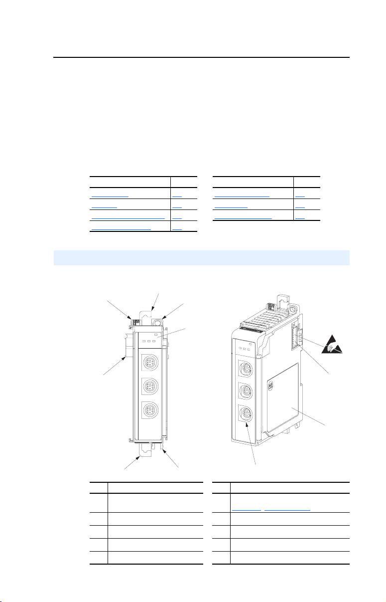
Components
Figure 1.1 Components of the Module
➊
1-1 Safety Precautions 1-4
➋
➍
➎
➏
rt
po
N
A
I / SC
P
D
C
H
1
C
H
2
C
H
3
➐
➌
MODULE
rt
CH1
CH2
CH3
po
N
A
I / SC
P
D
C
H
1
C
H
2
C
H
3
Item Part Item Part
Bus lever (with locking function)
➊
Upper DIN rail latch
➋
Lower DIN rail latch
➌
Upper panel mounting tab
➍
Lower panel mounting tab
➎
Module and drive status indicators. See
➏
Chapter
Movable bus connector with female pins
➐
Bus connector with male pins
➑
Nameplate label
➒
DPI/SCANport connectors
➓
MODULE
CH1
CH2
CH3
➓
8, Troubleshooting for details.
➑
➒
Page 14

1-2 Getting Started
Features
The 1769-SM1 Compact I/O to DPI/SCANport module features the
following:
• The module can be used as expansion I/O on MicroLogix 1500 and
CompactLogix controllers or with a remote 1769-based adapter. It
receives the required power from the Compact I/O backplane.
• The module automatically detects the DPI or SCANport Host
connected to a channel, and autobauds to the Host’s data rate.
• A number of configuration tools can be used to configure the module
and connected drive. For DPI products, the tools include the
PowerFlex HIM on the drive, network software such as RSNetWorx
for DeviceNet, or drive-configuration software such as
DriveExplorer (version 3.01 or higher) or DriveExecutive (version
1.01 or higher). For SCANport products, the tool is the controller
configuration software.
• I/O messaging, including Logic Command/Reference and up to four
bi-directional pairs of Datalinks (parameter read/write) for each
module channel, may be configured for your application using a
module parameter.
• The following table shows the various controllers that can be used
with the 1769-SM1 and whether they can support explicit messaging
(parameter read/write, etc.):
Controller Used With 1769-SM1
MicroLogix 1500 LSP Series A, B, and C ✔
MicroLogix 1500 LRP Series A and B ✔
MicroLogix 1500 LRP Series C ✔
CompactLogix 1769-L20 ✔
CompactLogix 1769-L30 ✔
CompactLogix 1769-L32E ✔
CompactLogix 1769-L35E ✔
1769-ADN DeviceNet Adapter ✔
• User-defined fault actions determine how the module and connected
drives respond when the controller is in idle mode.
• Bi-color (red/green) status indicators report the status of the module
and channel communications.
Supports Explicit Messaging
Yes No
Page 15

Getting Started 1-3
DPI Compatible Products
The 1769-SM1 module is compatible with Allen-Bradley PowerFlex
7-Class drives and other products that support DPI. At the time of
publication, compatible products include:
• PowerFlex 70 drives (standard and enhanced control)
• PowerFlex 700 drives (standard and vector control)
• PowerFlex 700 Ser. B drives (standard and vector control)
• PowerFlex 700H drives
• PowerFlex 700S drives (Phase I and Phase II control)
• PowerFlex 700 Liquid-Cooled drives
• PowerFlex 7000 drives
• SMC Flex
SCANport Compatible Products
The 1769-SM1 module is compatible with drives and other products that
support SCANport. At the time of publication, compatible products include:
• 1305 drives • 1336 REGEN drives • 2364F RGU
• 1336 PLUS drives • 1336 SPIDER drives • SMC Dialog Plus
• 1336 PLUS II drives • 1394 Servo drives • SMP-3
• 1336 IMPACT drives • 1397 drives •
• 1336 FORCE drives • 1557 drives •
Required Equipment
Equipment Shipped with the Module
When you unpack the module, verify that the package includes:
❑ One 1769-SM1 module
❑ This manual
User-Supplied Equipment
To install and configure the 1769-SM1 module, you must supply:
❑ A small flathead screwdriver
❑ Bulletin 1202 Communications Cables (1202-C*)
❑ A configuration tool, such as:
• For drives supporting DPI (PowerFlex):
– PowerFlex HIM on the PowerFlex drive
– DriveExplorer software (version 3.01 or higher)
– DriveExecutive stand-alone software (version 1.01 or higher) or
bundled with the DriveTools SP suite (version 1.01 or higher)
– RSNetWorx for DeviceNet
• For drives supporting SCANport or DPI (PowerFlex):
– Controller configuration software (e.g., RSLogix 500/5000)
Page 16
1-4 Getting Started
Safety Precautions
Please read the following safety precautions carefully.
ATTENTION: Risk of injury or death exists. The drive may contain
high voltages that can cause injury or death. Remove all power from the
!
drive, and then verify power has been removed before installing or
removing the module.
ATTENTION: Risk of injury or equipment damage exists. Only
personnel familiar with drive and power products and the associated
!
machinery should plan or implement the installation, start-up,
configuration, and subsequent maintenance of the product using the
module. Failure to comply may result in injury and/or equipment
damage.
ATTENTION: Risk of injury or equipment damage exists. DPI and
SCANport host products must not be directly connected together via
!
1202-C* communications cables. Unpredictable behavior due to timing
and other internal procedures can result if two or more devices are
connected in this manner.
ATTENTION: Risk of injury or equipment damage exists. If the
module is transmitting control I/O to the drive, the drive may fault when
!
you reset the module. Determine how your drive will respond before
resetting the module.
ATTENTION: Risk of injury or equipment damage exists.
Parameters 09 - [Idle Action 1], 26 - [Idle Action 2], and 43 - [Idle
!
Action 3] let you determine the action of the module and connected
drives if communications are disrupted. By default, these parameters
fault the drive. You can set these parameters so that the drive continues
to run. Precautions should be taken to ensure that the settings of these
parameters do not create a risk of injury or equipment damage.
ATTENTION: Risk of injury or equipment damage exists. When a
system is configured for the first time, there may be unintended or
!
incorrect machine motion. Disconnect the motor from the machine or
process during initial system testing.
ATTENTION: Risk of injury or equipment damage exists. The
examples in this publication are intended solely for purposes of
!
example. There are many variables and requirements with any
application. Rockwell Automation, Inc. does not assume responsibility
or liability (to include intellectual property liability) for actual use of
the examples shown in this publication.
Page 17

Getting Started 1-5
ATTENTION: This equipment is intended for use in a Pollution
Degree 2 industrial environment, in overvoltage Category II
!
applications (as defined in IEC publication 60664-1), at altitudes up to
2000 meters without derating.
This equipment is considered Group 1, Class A industrial equipment
according to IEC/CISPR Publication 11. Without appropriate
precautions, there may be potential difficulties ensuring
electromagnetic compatibility in other environments due to conducted
as well as radiated disturbance.
This equipment is supplied as “open type” equipment. It must be
mounted within an enclosure that is suitably designed for those specific
environmental conditions that will be present and appropriately
designed to prevent personal injury resulting from accessibility to live
parts. The interior of the enclosure must be accessible only by the use
of a tool. Subsequent sections of this publication may contain
additional information regarding specific enclosure type ratings that are
required to comply with certain product safety certifications.
See NEMA Standards publication 250 and IEC publication 60529, as
applicable, for explanations of the degrees of protection provided by
different types of enclosure. Also, see the appropriate sections in this
publication, as well as the Allen-Bradley publication 1770-4.1
(“Industrial Automation Wiring and Grounding Guidelines”), for
additional installation requirements pertaining to this equipment.
Page 18
1-6 Getting Started
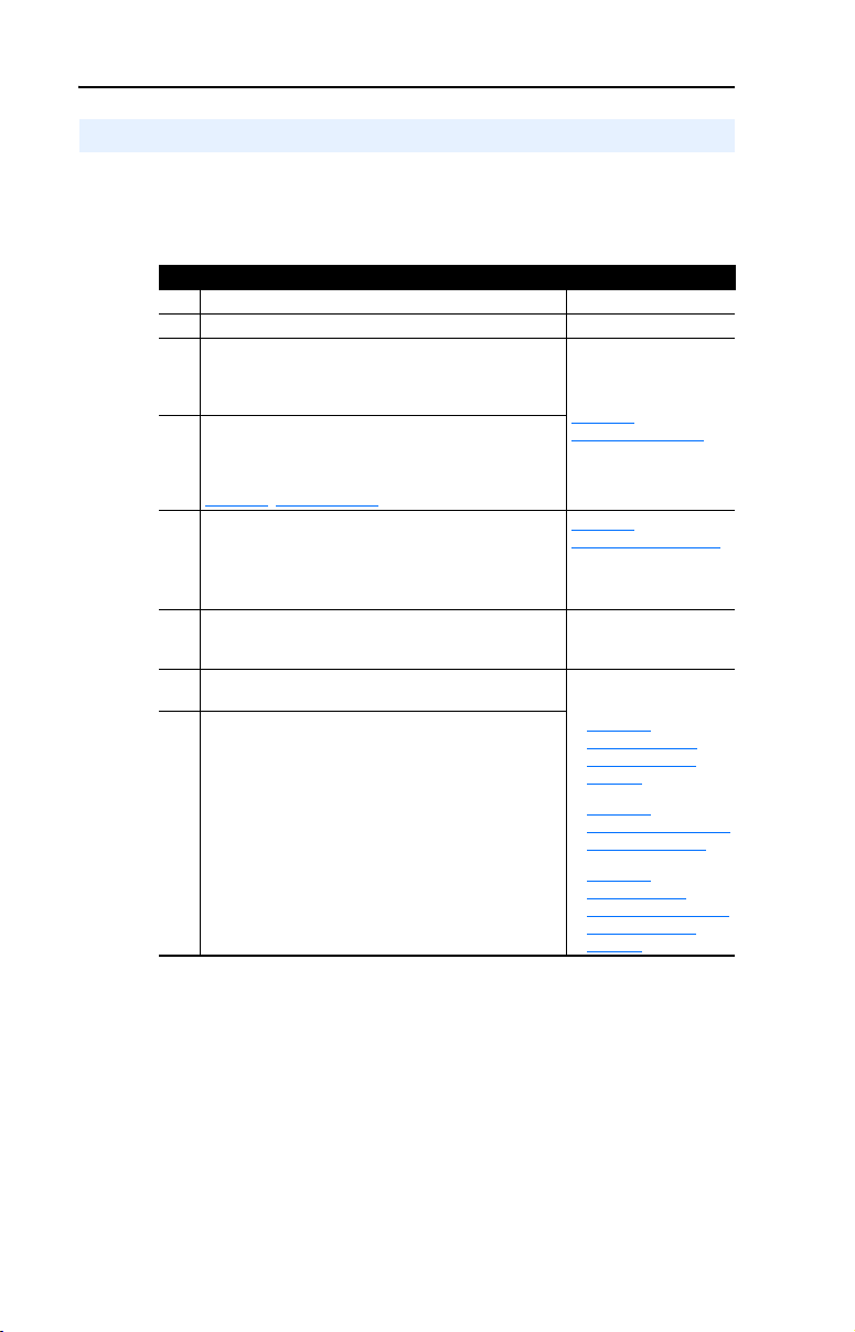
Quick Start
This section is provided to help experienced users quickly start using the
1769-SM1 Compact I/O to DPI/SCANport module. If you are unsure
how to complete a step, refer to the referenced chapter.
Step Action Refer to…
1 Review the safety precautions for the module. Throughout this manual
2 Verify that the drive is properly installed. Drive User Manual
3 Install the module.
Verify that the controller is not powered. Then, connect
the module to the controller backplane bus, and to the
drive using a Bulletin 1202-Cxx communications cable.
4 Apply power to the module.
The module receives power from the controller. Apply
power to the controller. The MODULE indicator should
be green. If it flashes red, there is a problem. Refer to
Chapter
5 Configure the module for your application.
Set the following parameters for the module as required
by your application:
• I/O configuration.
• Fault actions.
6 Apply power to the drive.
Verify that the drive is installed properly, and then apply
power to it.
7 Configure the controller to communicate with the
module.
8 Create a ladder logic program.
Use a programming tool such as RSLogix to create a
ladder logic program that enables you to do the
following:
• Control the module and connected drive.
• Monitor or configure the drive using Explicit
Messages.
8, Troubleshooting.
Chapter
2,
Installing the Module
Chapter
3,
Configuring the Module
Network Cable System
Planning and Installation
Manual
Depending on controller
type:
• Chapter
• Chapter 6,
• Chapter 7,
5,
MicroLogix 1500
Ladder Example
Program
CompactLogix Ladder
Example Program
ControlLogix w/
1769-ADN DeviceNet
Ladder Example
Program
Page 19
Getting Started 1-7
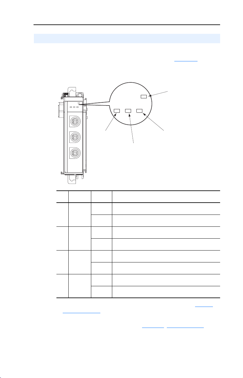
Modes of Operation
The module uses four status indicators to report its operating status.
They can be viewed on the front of the module. See Figure 1.2.
Figure 1.2 Status Indicators
➊
➋
MODULE
CH1
CH2
CH3
➍
➌
t
or
p
N
A
PI / SC
D
C
H
1
C
H
2
C
H
3
CH1
MODULE
CH2 CH3
Item Status
Indicator
MODULE Green Normal Operation. The module has established
➊
CH1 Green Normal Operation. CH1 is operating and is transferring I/O
➋
CH2 Green Normal Operation. CH2 is operating and is transferring I/O
➌
CH3 Green Normal Operation. CH3 is operating and is transferring I/O
➍
(1)
If all status indicators are off, the module is not receiving power. Refer to Chapter 2,
Installing the Module
(1)
Status
Flashing
Green
Flashing
Green
Flashing
Green
Flashing
Green
Description
communications with the controller.
The module is establishing communications with the
controller.
data between the controller and the drive.
Normal Operation. CH1 is operating but is not transferring
I/O data between the controller and the drive.
data between the controller and the drive.
Normal Operation. CH2 is operating but is not transferring
I/O data between the controller and the drive.
data between the controller and the drive.
Normal Operation. CH3 is operating but is not transferring
I/O data between the controller and the drive.
for instructions on installing the module.
If any other conditions occur, refer to Chapter 8, Troubleshooting.
Page 20

1-8 Getting Started
Notes:
Page 21

Chapter 2
Installing the Module
Chapter 2 provides instructions for installing the 1769-SM1 module as
an expansion I/O module on MicroLogix 1500 and CompactLogix
controllers, or with a remote 1769-based adapter.
Topic Page Topic Page
Preparing for an Installation
Removing Power 2-2 Grounding the Module 2-8
Selecting the Configuration Mode 2-2 Connecting the Module to the Drive 2-9
Assembling the Module to the Controller 2-3 Applying Power 2-9
Preparing for an Installation
Consider the following when installing the 1769-SM1 module:
2-1 Mounting the Module 2-4
• Verify that you have all required equipment. Refer to Chapter 1
Getting Started.
• A MicroLogix 1500 Base Unit or Compact I/O power supply has
limits in the amount of +5V dc and +24V dc current it can supply to
modules in its I/O bank. These limits depend on the catalog number
(e.g. 1769-PA2) of the supply. A bank of modules must not exceed
the current limits of the MicroLogix 1500 Base Unit or I/O bank
power supply.
Refer to the MicroLogix 1500 User Manual (Publication No.
1764-UM001…), or the Compact 1769 Expansion I/O Power
Supplies Installation Instructions (Publication No. 1769-5.14).
• The 1769-SM1 module has a distance rating of six, therefore the
module must be within six modules of the I/O bank’s power supply.
ATTENTION: Risk of equipment damage exists. The 1769-SM1
module contains ESD (Electrostatic Discharge) sensitive parts that can
!
be damaged if you do not follow ESD control procedures. Static control
precautions are required when handling the module. If you are
unfamiliar with static control procedures, refer to Guarding Against
Electrostatic Damage, Publication 8000-4.5.2.
,
Page 22
2-2 Installing the Module
Removing Power
ATTENTION: Risk of equipment damage exists. Remove power
before installing or removing the 1769-SM1 module. When you install
!
or remove the module with power applied, an electrical arc may occur.
An electrical arc can cause personal injury or equipment damage by:
• Sending an erroneous signal to your system’s field devices, causing
unintended machine motion.
• Causing an explosion in a hazardous environment.
Electrical arcing causes excessive wear to contacts on both the module
and its mating connector. Worn contacts may create electrical
resistance.
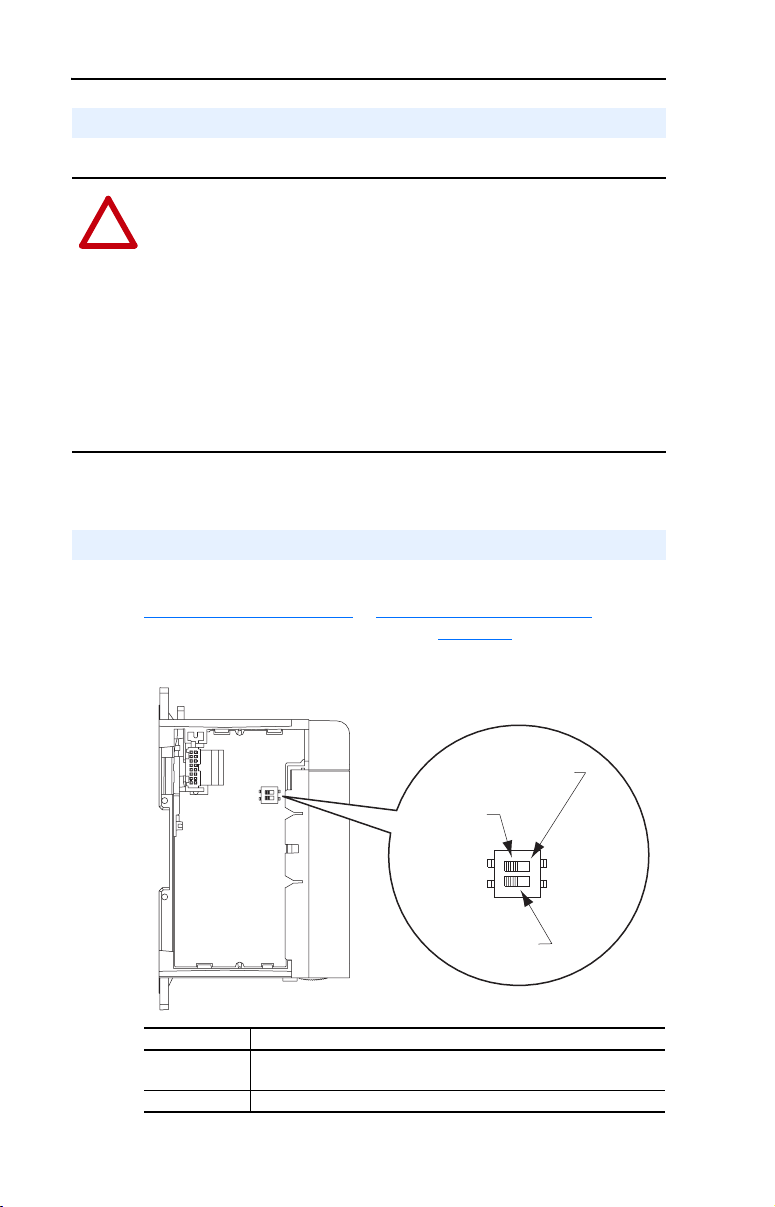
Selecting the Configuration Mode
For detailed information on both configuration modes, please refer to
Controller Mode
the module Configuration Mode switch (Figure 2.1).
on page 3-2 or Parameter Mode on page 3-13. Then set
Figure 2.1 Setting the Configuration Mode Switch
PARAM
PARAM
Position
Position
CONT
CONT
Position
Position
Unused
Unused
Switch
Switch
Switch Setting Description
Controller
(Default)
Parameter 1769-SM1 uses its internal parameter setting to configure the module.
1769-SM1 uses the configuration data downloaded from the controller
on power-up and when the controller is placed in run mode.
Page 23
Installing the Module 2-3
Assembling the Module to the Controller
The 1769-SM1 module can be attached to adjacent controller modules
before or after mounting. For mounting instructions, see Panel
Mounting on page 2-4 or DIN Rail Mounting on page 2-7. To work with
a system that is already mounted, see Replacing the Module within a
System on page 2-7.
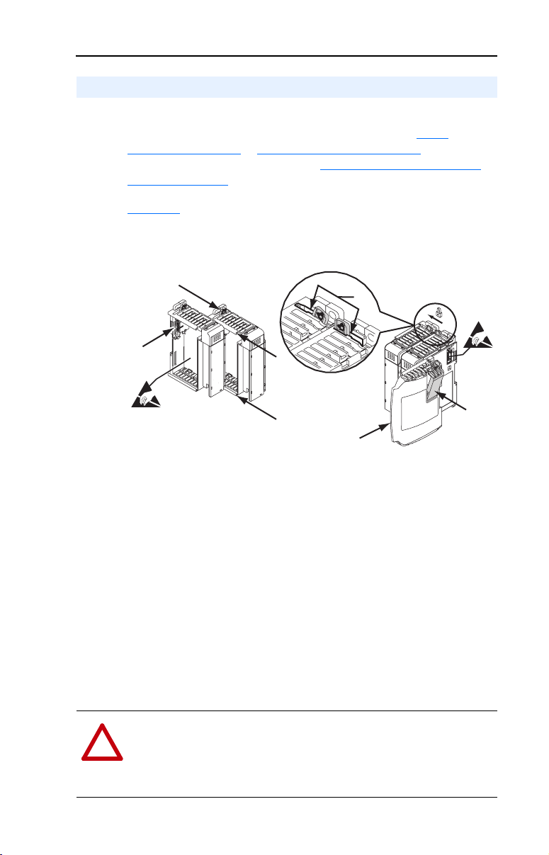
Figure 2.2 and the following procedure shows you how to assemble the
Compact I/O system.
Figure 2.2 Assembling 1769-SM1 Module to Compact I/O System
A
D
E
C
B
B
1. Disconnect power.
2. Check that the bus lever (A) of the 1769-SM1 module is in the
unlocked (fully right) position.
3. Use the upper and lower tongue-and-groove slots (B) to secure the
modules together.
4. Move the 1769-SM1 module back along the tongue-and-groove slots
until the bus connectors (C) line up with each other.
5. Use your fingers or a small screwdriver to push the bus lever back
slightly to clear the positioning tab (D).
6. Move the 1769-SM1 module’s bus lever fully to the left (E) until it
clicks. Ensure it is locked firmly in place.
ATTENTION: Risk of equipment damage exists. When attaching the
1769-SM1 module to a Compact I/O system, it is very important that
!
the bus connectors are securely locked together to ensure proper
electrical connection. Failure to do this may cause an electrical arc,
which can cause personal injury or equipment damage.
F
G
Page 24
2-4 Installing the Module
7. Attach an end cap terminator (F) to the last module in the system by
using the tongue-and-groove slots as before.
8. Lock the end cap bus terminator (G).
Important: A 1769-ECR or 1769-ECL right or left end cap must be
Mounting the Module
ATTENTION: Risk of equipment damage exists. During panel or
DIN rail mounting of all devices, be sure that all debris (metal chips,
!
wire strands, etc.) is kept from falling into the 1769-SM1 module.
Debris that falls into the module could cause damage on power up.
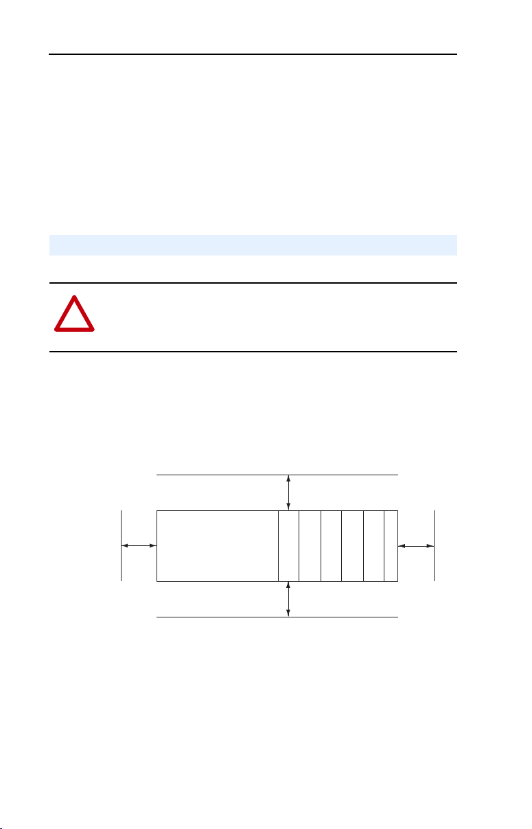
Minimum Spacing
Maintain spacing from enclosure walls, wireways, adjacent equipment,
etc. Allow 50 mm (2 in.) of space on all sides for adequate ventilation as
shown:
used to terminate the end of the serial communication
bus.
To p
Side
Allow at least 140 mm (5.5 in.) of enclosure depth to accommodate the
1769-SM1 module.
Panel Mounting
Mount the 1769-SM1 module to a panel using two screws per module.
Use M4 or #8 panhead screws. Mounting screws are required on every
module.
Controller
Compact I/O
Compact I/O
Bottom
Compact I/O
Compact I/O
Compact I/O
End Cap or Cable
Side
Page 25
Installing the Module 2-5
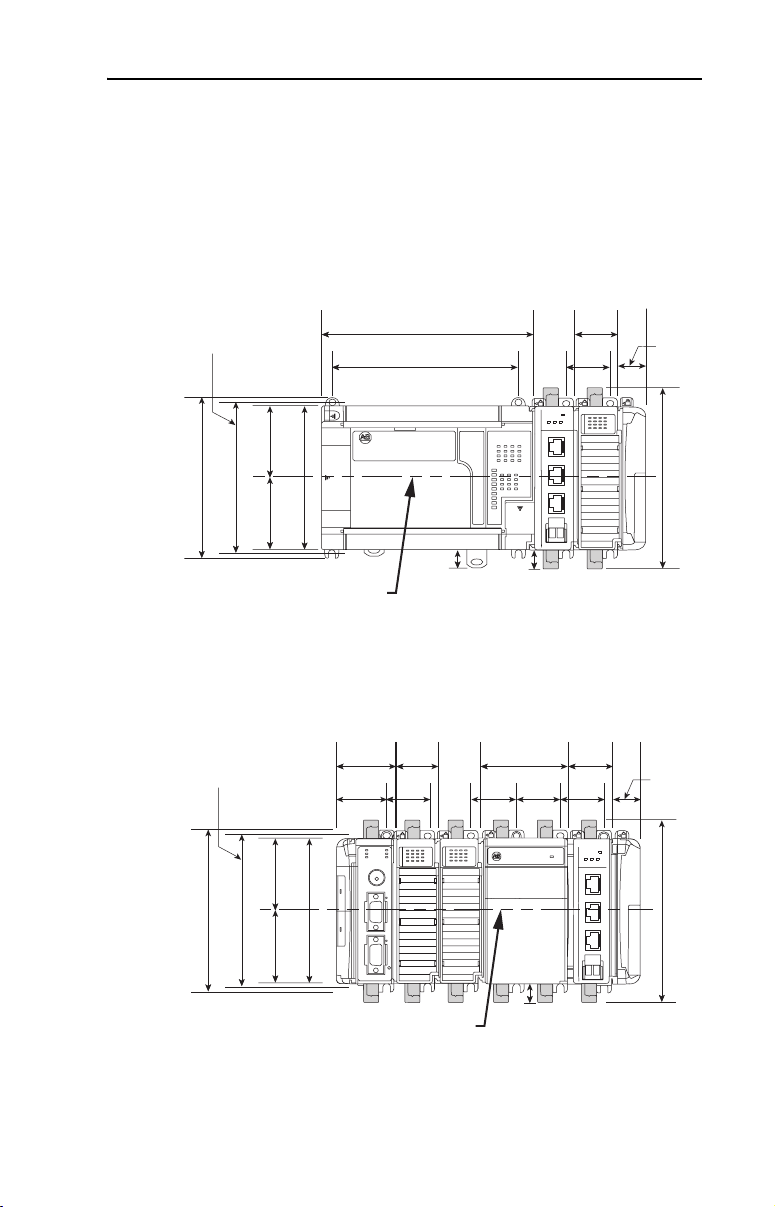
Panel Mounting Using the Dimensional Drawing
NOTE: All dimensions are in mm (inches). Hole spacing tolerance:
±0.04 mm (0.016 in.).
Figure 2.3 1769-SM1 Module with MicroLogix 1500 Base Unit and Processor
Mounting Hole
Dimension
132 mm (5.19 in)
122.6 mm (4.83 in)
59 mm
59 mm
(2.32 in)
(2.32 in)
118 mm (4.65 in)
168 mm
(6.62 in)
147 mm
(5.79 in)
DPI / SCANport
C
H
1
C
H
2
C
H
3
DIN Rail
Center Line
13.5 mm
(0.53 in)
Figure 2.4 1769-SM1 Module with CompactLogix Controller
35 mm
Mounting Hole
Dimension
50 mm
(1.97 in)
40 mm
(1.58 in)
(1.38 in)
35 mm
(1.38 in)
35 mm
(1.38 in)
14.7 mm
(0.58 in)
70 mm
(2.76 in)
35 mm
(1.38 in)
59 mm
(2.32 in)
132 mm (5.19 in)
122.6 mm (4.83 in)
118 mm (4.65 in)
59 mm
(2.32 in)
CH1
MODULE
CH2
CH3
35 mm
(1.38 in)
35 mm
(1.38 in)
35 mm
(1.38 in)
35 mm
(1.38 in)
MODULE
ort
CH1
CH2
CH3
DPI / SCANp
C
H
1
C
H
2
C
H
3
28.5 mm
(1.12 in)
147.4 mm (5.81 in)
28.5 mm
(1.12 in)
147.4 mm (5.81 in)
DIN Rail
Center Line
14.7 mm
(0.58 in)
Page 26
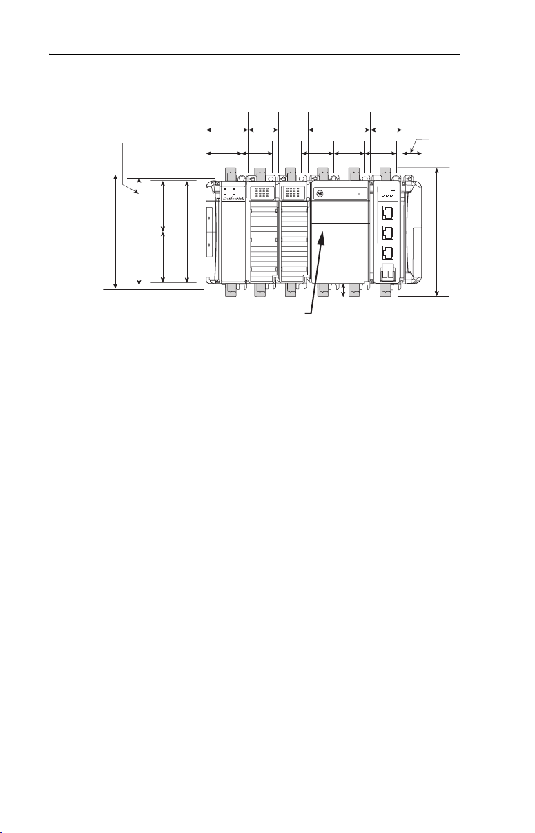
2-6 Installing the Module
Figure 2.5 1769-SM1 Module with Remote 1769-Based Adapter
35 mm
(1.38 in)
35 mm
(1.38 in)
35 mm
(1.38 in)
CH1
Nport
CA
DPI / S
C
H
1
C
H
2
C
H
3
28.5 mm
(1.12 in)
MODULE
CH2
CH3
147.4 mm (5.81 in)
35 mm
(1.38 in)
70 mm
(2.76 in)
14.7 mm
(0.58 in)
35 mm
Mounting Hole
Dimension
59 mm
(2.32 in)
132 mm (5.19 in)
122.6 mm (4.83 in)
59 mm
(2.32 in)
Panel Mounting Procedure Using Module as a Template
50 mm
(1.97 in)
40 mm
(1.58 in)
MS
IO
118 mm (4.65 in)
(1.38 in)
35 mm
(1.38 in)
NS
DIAG
DIN Rail
Center Line
The following procedure enables you to use the assembled modules as a
template for drilling holes in the panel. Due to module mounting hole
tolerance, it is important to follow these steps:
1. On a clean work surface, assemble no more than three modules.
2. Using the assembled modules as a template, carefully mark the
center of all module-mounting holes on the panel.
3. Return the assembled modules to the clean work surface, including
any previously mounted modules.
4. Drill and tap the mounting holes for the recommended M4 or #8
screw.
5. Place the modules back on the panel, and check for proper hole
alignment.
6. Attach the modules to the panel using the mounting screws.
Page 27

Installing the Module 2-7
DIN Rail Mounting
The 1769-SM1 module can be mounted using the following DIN rails:
• 35 x 7.5 mm (EN 50 022 - 35 x 7.5)
• 35 x 15 mm (EN 50 022 - 35 x 15)
Before mounting the module on a DIN rail, close the DIN rail latches.
Press the DIN rail mounting area of the module against the DIN rail. The
latches will momentarily open and lock into place.
Replacing the Module within a System
The 1769-SM1 module can be replaced while the system is mounted to a
panel (or DIN rail).
1. Remove power.
ATTENTION: Risk of equipment damage exists. Remove power
before installing or removing the 1769-SM1 module. When you install
!
or remove the module with power applied, an electrical arc may occur.
An electrical arc can cause personal injury or equipment damage by:
• Sending an erroneous signal to your system’s field devices, causing
unintended machine motion.
• Causing an explosion in a hazardous environment.
Electrical arcing causes excessive wear to contacts on both the module
and its mating connector. Worn contacts may create electrical
resistance.
2. Unplug the 1202-C* communications cable from each port (CH1,
CH2, CH3) on the 1769-SM1 module. Note each drive and the port
to which it is connected.
3. Remove the upper and lower mounting screws from the module (or
open the DIN latches using a flat-blade screwdriver).
4. On the right-side adjacent module, move its bus lever to the right
(unlock) to disconnect it from the module being removed.
Page 28

2-8 Installing the Module
5. Gently slide the disconnected 1769-SM1 module forward.
If you feel excessive resistance, make sure that you disconnected the
module from the bus and that you removed both mounting screws (or
opened the DIN latches).
TIP: It may be necessary to rock the module slightly from
front to back to remove it, or, in a panel-mounted system,
to loosen the screws of adjacent modules.
6. Before installing the replacement 1769-SM1 module, be sure that the
bus lever on the right-side adjacent module is in the unlocked (fully
right) position.
7. Slide the replacement 1769-SM1 module into the open slot.
8. Connect the 1769-SM1 module and adjacent modules together by
locking (fully left) the bus levers on the 1769-SM1 module and the
right-side adjacent module.
9. Replace the mounting screws (or snap the module onto the DIN rail).
10. Plug the appropriate 1202-C* communications cable into its
respective port on the 1769-SM1 module.
11. Restore 1769-SM1 module configuration using an appropriate
configuration tools.
Grounding the Module
The 1769-SM1 module is intended to be mounted to a well-grounded
mounting surface such as a metal panel. Additional grounding
connections from the module’s mounting tabs or DIN rail (if used) are
not required unless the mounting surface cannot be grounded. For
additional information, refer to Industrial Automation Wiring and
Grounding Guidelines (Publication No. 1770-4.1).
Page 29

Installing the Module 2-9
Connecting the Module to the Drive
1. Plug one male end of a 1202-C* communications cable into a desired
port (CH1, CH2 or CH3) on the 1769-SM1 module.
2. Plug the other male end of the cable into the port on the desired
drive.
Note: For EMC regulatory compliance, there is a maximum cable
distance limit per channel. Please see Regulatory Compliance
page A-2 for more information. For general cable information, please
see DPI/SCANport Cable Requirements/Recommendations on
page A-2.
Applying Power
ATTENTION: Risk of equipment damage, injury, or death exists.
Unpredictable operation may occur if you fail to verify that parameter
!
settings are compatible with your application. Verify that settings are
compatible with your application before applying power to the drive.
on
1. Apply power to the controller. The status indicators can be viewed on
the front of the 1769-SM1 module after power has been applied.
2. The module is assigned a unique network address by the bus master
during initialization.
3. Apply power to the drive. When you apply power to the 1769-SM1
module, controller, and network for the first time, the status
indicators should be green after an initialization. If the status
indicators go red, there is a problem. Refer to Chapter
Troubleshooting.
8,
Page 30

2-10 Installing the Module
Notes:
Page 31

Chapter 3
Configuring the Module
Chapter 3 provides instructions and information for configuring the
1769-SM1 module.
Topic Page Topic Page
Configuration Tools
Configuration Methods 3-2 Setting an Idle Action 3-16
Controller Mode 3-2 Resetting the Module 3-17
Parameter Mode 3-13 Viewing the Module Configuration 3-18
Using the PowerFlex HIM 3-14
3-1 Setting the I/O Configuration 3-15
For a list of parameters, refer to Appendix
definitions of terms in this chapter, refer to the Glossary.
B, Module Parameters. For
Configuration Tools
The 1769-SM1 module stores parameters and other information in its
own non-volatile memory. You must, therefore, access the module to
view and edit its parameters. The following tools can be used to access
the module parameters.
For DPI (PowerFlex)-Supported System:
Tool Refer to…
DriveExplorer Software
(version 3.01 or higher)
DriveExecutive Software
(version 1.01 or higher)
PowerFlex HIM on PowerFlex drive Page 3-14
RSLogix 500 LG500-GR001…
RSLogix 5000 9399-RLD300GR
For SCANport or DPI (PowerFlex)-Supported System:
Tool Refer to…
RSLogix 500 LG500-GR001…
RSLogix 5000 9399-RLD300GR
http://www.ab.com/drives/driveexplorer, and
DriveExplorer online help (installed with the software
http://www.ab.com/drives/drivetools, and
DriveExecutive online help (installed with the software
Page 32

3-2 Configuring the Module
Configuration Methods
The 1769-SM1 has two methods for configuration, which are determined
by the Configuration Mode switch (Figure 2.1) on the module:
• Controller mode - The 1769-SM1 uses the configuration data
downloaded from the controller on power-up and when the controller
is placed in run mode.
• Parameter mode - The 1769-SM1 uses its internal parameter setting
to configure the module.
Only one type of configuration is selected, and it is used for all three
channels.
Controller mode is required if only
etc.) are connected to the module. This is because SCANport peripherals
(HIMs, etc.) cannot configure other peripherals, for example, the
1769-SM1. DPI products (PowerFlex 70, etc.) have the option of being
used in Controller mode.
If one or more DPI products (PowerFlex 70, etc.) are connected, even if a
SCANport product (1336 PLUS II, etc.) is also connected, Parameter
mode can be used. This is because DPI peripherals (20-HIMs, etc.) have
the ability to configure other peripherals connected to the PowerFlex
drive, for example, the 1769-SM1.
Controller Mode
When the Configuration Mode switch is in the default “Controller”
position, the 1769-SM1 uses the configuration data downloaded from the
controller on power-up and when the controller is placed in run mode.
Configuration data is allocated and entered using RSLogix500 or
RSLogix 5000, depending on the controller used. Controller mode can
be used for either DPI (PowerFlex 70, etc.) or SCANport (1336 PLUS II,
etc.) products.
The 1769-SM1 module contains 60 words of configuration data that are
used to configure the I/O data and the module's behavior when the
controller faults or is placed in program mode.
SCANport products (1336 PLUS II,
Page 33

Configuring the Module 3-3
Table 3.A Module Configuration Data Words in Controller Mode
Description CH1 Word CH2 Word CH3 Word
Idle Action / I/O Config
Fault Config. Logic Command
Fault Config. Reference (Low) *
Fault Config. Reference (High)
Fault Config Datalink In A1 (Low) * 12 16 20
Fault Config Datalink In A1 (High) 13 17 21
Fault Config Datalink In A2 (Low) * 14 18 22
Fault Config Datalink In A2 (High) 15 19 23
Fault Config Datalink In B1 (Low) *
Fault Config Datalink In B1 (High)
Fault Config Datalink In B2 (Low) *
Fault Config Datalink In B2 (High)
Fault Config Datalink In C1 (Low) * 36 40 44
Fault Config Datalink In C1 (High) 37 41 45
Fault Config Datalink In C2 (Low) * 38 42 46
Fault Config Datalink In C2 (High) 39 43 47
Fault Config Datalink In D1 (Low) *
Fault Config Datalink In D1 (High)
Fault Config Datalink In D2 (Low) *
Fault Config Datalink In D2 (High)
* Note: Data for 16-bit Reference or 16-bit Datalinks are entered in these locations.
0 4 8
1 5 9
2 6 10
3 7 11
24 28 32
25 29 33
26 30 34
27 31 35
48 52 56
49 53 57
50 54 58
51 55 59
Idle Action / I/O Config Setting
The format for the Idle Action / I/O Config word is:
Not Used Idle Action I/O Config
15 14 13 1211109876543210
The Idle Action setting is similar to the Parameter 09 - [Idle Action 1], 26 [Idle Action 2] and 43 - [Idle Action 3] settings, where:
Idle Action Decimal
11 10 9 8
0 0 0 0 0 Fault - the connected drive is faulted
0 0 0 1 1 Stop - a Stop command is sent to the drive
0 0 1 0 2 Zero Data - zero's are sent to the drive
0 0 1 1 3 Hold Last - previous data continues to be sent to the drive
0 1 0 0 4 Send Fault Config - fault config data is sent to the drive
0 1 0 1 5 Invalid
0 1 1 0 6 Invalid
0 1 1 1 7 Invalid
0 0 0 0 8 Invalid
(1)
“Stop” Idle Action is not supported for SCANport connected channels. If this setting is used, the “Fault” action will
be used instead.
Value
Description
(1)
Page 34

3-4 Configuring the Module
The I/O Config setting is similar to the Parameter 07 - [I/O Config 1],
24 - [I/O Config 2], and 41 - [I/O Config 3] settings, where:
I/O Config
7 6 543210
x x x
A “0” equals I/O disabled and a “1” equals I/O enabled. For example, a
“00001” enables Logic Command/Reference and Logic Status/
Feedback, and disables all of the Datalinks.
Fault Config Settings
Bit Definitions
0 = Logic Command/Reference and
Logic Status/Feedback
1 = Datalink A
2 = Datalink B
3 = Datalink C
4 = Datalink D
5 = not used
6 = not used
7 = not used
The 1769-SM1 uses the Fault Configuration data settings when an Idle
Fault is detected and the Idle Action = “4” (bit 10 = “1” and bits 11, 9, and
8 = “0”) in the Idle Action / I/O Config word. The Logic Command,
Reference, and Datalink configuration settings must be set to perform the
desired action. For example, to have a PowerFlex 70 connected to CH1
run forward at 30.0 Hz when a fault condition occurs, set:
Fault Config Logic Command (word 1) = 18**
**Bit 1 START and bit 4 FORWARD COMMAND are “1.”
Fault Config Reference (Low) (word 2) = 300
Entering MicroLogix 1500 Configuration Data using RSLogix 500
version 6.0 (or lower)
The configuration data is allocated and entered by performing the
following steps:
1. Double-click on I/O Configuration in the menu tree to open the I/O
Configuration window. Select OTHER and click the A
command button. A screen with an Expansion General Configuration
tab (Figure 3.1
) will appear.
dv Config
Page 35

Configuring the Module 3-5
Figure 3.1 I/O Configuration Window and Expansion General Configuration Screen
2. Enter the product data for the module as shown above (1, 109, 17,
and A), along with the desired Input and Output word length. Enter
“60” in the Extra Data Length field and click OK. From the I/O
Configuration window, click on the A
again and now there are two tabs available (Figure 3.2
dv Config command button
).
Figure 3.2 Expansion General Configuration Screen w/Generic Extra Data Config Tab
Page 36

3-6 Configuring the Module
3. Click on the Generic Extra Data Config tab (Figure 3.3) to display
the configuration data area. Enter the desired configuration data and
click OK when finished.
Figure 3.3 Data Area on Generic Extra Data Config Tab
The MicroLogix 1500 will download the configuration data to the
1769-SM1 when the controller is placed in run mode.
Entering MicroLogix 1500 Configuration Data using RSLogix 500
version 6.1 (or higher)
The configuration data is allocated and entered by performing the
following steps:
1. Double-click on I/O Configuration in the menu tree to open the I/O
Configuration window. Select the 1769-SM1 and click the A
Config command button. A screen with an Expansion General
Configuration tab (Figure 3.4
) will appear.
dv
Page 37

Configuring the Module 3-7
Figure 3.4 I/O Configuration Window and Expansion General Configuration Screen
2. Enter “60” in the Extra Data Length field and click Apply. “60” is
the number of configuration words used by the SM1 (20 words per
channel). New tabs (Figure 3.5
configuration.
) will appear to allow the
Figure 3.5 Expansion General Configuration Tab Screen
Page 38

3-8 Configuring the Module
3. Click on the Chan. 1 tab (Figure 3.6) and set the I/O Config data
area accordingly. In this example, Cmd/Ref and all Datalinks are
used.
Figure 3.6 Chan. 1 Tab Data Screen
Select the desired Idle Action. Note that the Fault Config Data area
(Figure 3.7) can only be accessed if Send Flt Cfg is enabled.
Figure 3.7 Chan. 1 Tab Data Screen with Idle Action - Send Flt Cfg Enabled
4. For each additional channel being used, select its respective tab, set
the desired I/O configuration, and enable the appropriate idle action.
Page 39

Configuring the Module 3-9
5. An alternate to using the Chan. 1-3 tabs to enter data is the Generic
Extra Data Config tab (Figure 3.8
identification purposes only. With the easy-to-use Chan.1-3 tabs,
there is no need to enter data using the Generic Extra Data Config
tab. However, it does show how the data in the configuration words
are stored in the controller.
Figure 3.8 Generic Extra Data Config Tab Screen
), which is being shown for
6. Click OK when finished. The MicroLogix 1500 will download the
configuration data to the 1769-SM1 when the controller is placed in
run mode.
Page 40

3-10 Configuring the Module
Entering CompactLogix Configuration Data using RSLogix 5000
version 10 (or higher)
The CompactLogix configuration data is allocated and entered by
performing the following steps:
1. Right-click on CompactBus Local in the menu tree (Figure 3.9
select New Module.
Figure 3.9 Menu Tree Window with New Module Inset Screen
2. Select the 1769-MODULE (Figure 3.10) and click OK.
Figure 3.10 Select Module Type Screen
) and
Page 41

Configuring the Module 3-11
3. In the Module Properties screen (Figure 3.11), enter a name for the
module, such as “My_1769_SM1.” Change the Comm F
“Data - INT,” which will enable the entry of Output Connection
parameters (no longer grayed out). Enter the Slot location of the
1769-SM1 and enter “60” for the I
Connection Parameters. Click Next >.
Figure 3.11 Module Properties Screen
nput, Output, and Configuration
ormat to
4. On the Module Properties last screen (Figure 3.12), click Finish >>.
Figure 3.12 Module Properties Last Screen
5. The menu tree (Figure 3.13) will now show the 1769-MODULE that
you created.
Figure 3.13 Menu Tree Window with Listed 1769-MODULE
Page 42

3-12 Configuring the Module
6. Double-clicking on Controller Tags or Program Tags in the menu
tree will display the various tags, including the tags for the
1769-SM1 module (Figure 3.14
the bottom of the window to enter the configuration data.
Figure 3.14 Controller Tags Screen
TIP: RSLogix 5000 creates a data array that is much larger than the 60
words previously specified when the module was configured. Use words
0 - 59 and ignore words 60 - 197. Also, note the data entry format in
Figure 3.14
appropriate field in the “Style” column.
is hexadecimal (16#). To change the format, click on the
). Click on the Monitor Tags tab at
The CompactLogix controller will download the configuration data to
the 1769-SM1 module on power-up.
Page 43

Configuring the Module 3-13
Parameter Mode
When the Configuration Mode switch is in the “Parameter” position, the
1769-SM1 uses its internal parameters setting to configure the module.
Any configuration data downloaded by the controller will be ignored.
Important: When the Parameter mode is used, the configuration data size
in the controller should be set to “0.” Refer to Controller
Mode on page 3-2 for more information.
Table 3.B Module Configuration Data Words in Parameter Mode
Description
I/O Config 7 24 41
Idle Action 9 26 43
Fault Config. Logic Command 10 27 44
Fault Config. Reference 11 28 45
Fault Config Datalink In A1 12 29 46
Fault Config Datalink In A2 13 30 47
Fault Config Datalink In B1 14 31 48
Fault Config Datalink In B2 15 32 49
Fault Config Datalink In C1 16 33 50
Fault Config Datalink In C2 17 34 51
Fault Config Datalink In D1 18 35 52
Fault Config Datalink In D2 19 36 53
CH1
Parameter
CH2
Parameter
CH3
Parameter
Only DPI products (PowerFlex 70, etc.) can utilize this feature since DPI
peripheral devices (HIMs, DriveExplorer with 1203-SSS converter, etc.)
can access the 1769-SM1 directly. Allowing DPI peripherals to change
the configuration settings makes the Parameter mode more flexible and
simpler to use than Controller mode.
Figure 3.15 DriveExplorer Window with Mapped 1769-SM1 Compact I/O Module
Page 44

3-14 Configuring the Module
Using the PowerFlex HIM
If your drive has either an LED or LCD HIM (Human Interface Module),
access parameters in the 1769-SM1 module as shown below. It is
recommended that you read through the steps for your HIM before
performing the sequence. For additional HIM information, refer to your
PowerFlex Drive User Manual or the HIM Quick Reference card.
Using an LED HIM
Step Key(s) Example Screens
1. Press the ALT and then Sel
(Device) to display the Device
Screen.
2. Press the Up Arrow or Down
Arrow to scroll to the 1769-SM1
module. Letters represent files in
the drive, and numbers represent
ports. The module is usually
connected to port 2.
3. Press the Enter key to enter your
selection. A parameter database
is constructed, and then the first
parameter is displayed.
4. Edit the parameters using the
same techniques that you use to
edit drive parameters.
ALT
Device
Sel
OR
Using an LCD HIM
Step Key(s) Example Screens
1. In the main menu, press the Up
Arrow or Down Arrow to scroll to
Device Select.
2. Press Enter to enter your
selection.
3. Press the Up Arrow or Down
Arrow to scroll to the 1769-SM1
module.
4. Press Enter to select the module.
A parameter database is
constructed, and then the main
menu for the module is
displayed.
5. Edit the parameters using the
same techniques that you use to
edit drive parameters.
OR
OR
F-> Stopped Auto
0.00 Hz
Main Menu:
Diagnostics
Param ete r
Device Select
Por t 2 Device
1769-SM1
Main Menu:
Diagnostics
Param ete r
Device Select
Page 45

Configuring the Module 3-15
Setting the I/O Configuration
The I/O configuration determines the type of data sent to the drive. Logic
Command/Status, Reference/Feedback, and Datalinks may be enabled or
disabled. A “1” enables the I/O. A “0” disables it.
1. Set the bits in Parameters 07 - [I/O Config 1], 24 - [I/O Config 2],
and 41 - [I/O Config 3] for each respective drive:
Figure 3.16 I/O Configuration Screen for CH1 Drive on an LCD HIM
Port 2 Device
1769-SM1
Parameter #: 07
I/O Config 1
xxxx xxxx xxx0 000
Cmd/Ref b00
Bit 0 is the right-most bit. In Figure 3.16, it is highlighted and equals
“1.”
2. If you enabled Logic Command/Reference, configure the drive to
accept the Logic Command and Reference from the 1769-SM1
module. For example, set parameter 90 - [Speed Ref A Sel] in a
PowerFlex 70 or 700 drive to “DPI Port 2” so that the drive uses the
Reference from the module. Also, verify that the mask parameters in
the drive (for example, parameter 276 - [Logic Mask]) are configured
to receive the desired logic from the module.
Bit Description
0 Logic Command/Reference (Default)
1 Datalink A
2 Datalink B
3 Datalink C
1
4 Datalink D
5 - 15 Not Used
3. If you enabled one or more Datalinks, configure the drive to
determine the source and destination of data in the Datalink(s). Also,
ensure that the 1769-SM1 module is the only module using the
enabled Datalink(s).
4. Reset the module (see Resetting the Module
on page 3-17).
Page 46

3-16 Configuring the Module
Setting an Idle Action
By default, when the controller is idle, the drive responds by faulting if it
is using I/O from the 1769-SM1. You can configure a different response
to an idle controller using Parameters 09 - [Idle Action 1], 26 - [Idle
Action 2], and 43 - [Idle Action 3] for each respective connected drive.
ATTENTION: Risk of injury or equipment damage exists.
Parameters 09 - [Idle Action 1], 26 - [Idle Action 2], and 43 - [Idle
!
Action 3] let you determine the action of the 1769-SM1 module and
each connected drive if communications are disrupted or the controller
is idle. By default, each of these parameters faults its respective drive.
You can set each parameter so that the respective drive continues to run.
Precautions should be taken to ensure that the settings of these
parameters do not create a hazard of injury or equipment damage.
To change the Idle Action
Set the values of Parameters 09 - [Idle Action 1], 26 - [Idle Action 2],
and 43 - [Idle Action 3] to the desired responses:
Value Action Description
0 Fault (default) The drive is faulted and stopped. (Default)
1 Stop The drive is stopped, but not faulted.
2 Zero Data The drive is sent 0 for output data after a communications
3 Hold Last The drive continues in its present state after a communications
4 Send Flt Cfg The drive is sent the data that you set in the fault configuration
(1)
“Stop” Idle Action is not supported for SCANport connected channels. If this setting is used, the
“Fault” action will be used instead.
Figure 3.17 Fault Action Screens on an LCD HIM
(1)
disruption. This does not command a stop.
disruption.
parameters (e.g. Parameter 10 - [Flt Cfg Logic 1] through
Parameter 19 - [Flt Cfg D2 In1] for CH1 drive).
Port 2 Device
1769-SM1
Parameter #: 09
Idle Action 1
0
Fault
Changes to these parameters take effect immediately. A reset is not
required.
Port 2 Device
1769-SM1
Parameter #: 26
Idle Action 2
0
Faul t
Port 2 Device
1769-SM1
Parameter #: 43
Idle Action 3
0
Faul t
Page 47

Configuring the Module 3-17
To set the fault configuration parameters
If you set Parameter 09 - [Idle Action 1], 26 - [Idle Action 2], or 43 [Idle Action 3] to “Send Flt Cfg,” the values in the following 1769-SM1
module parameters are sent to the drive after an idle action occurs. You
must set these parameters to values required by your application.
Parameter
CH1 CH2 CH3
10 27 44 Flt Cfg Logic A 16-bit value sent to the drive for Logic
11 28 45 Flt Cfg Ref A 32-bit value (0 – 4294967295) sent to the
12 - 19 29 - 36 46 - 53 Flt Cfg x1 In
Changes to these parameters take effect immediately. A reset is not required.
Name Description
Command.
drive as a Reference or Datalink.
or
Flt Cfg x2 In
Important: If the drive uses a 16-bit
Reference or 16-bit Datalinks, the most
significant word of the value should be set to
zero (0).
Resetting the Module
Changes to settings on some module parameters require that you reset
the 1769-SM1 module before the new settings take effect. You can reset
the module by cycling power to the module or by using Parameter 02 -
[Reset Module]:
ATTENTION: Risk of injury or equipment damage exists. If the
module is transmitting control I/O to the drive, the drive may fault when
!
you reset the module. Determine how your drive will respond before
resetting a connected module.
Set the Parameter 02 - [Reset Module] to Reset Module:
Figure 3.18 Reset Screen on an LCD HIM
Port 2 Device
1769-SM1
Parameter #: 02
Reset Module
1
Reset Module
Value Description
0 Ready (Default)
1 Reset Module
2 Set Defaults
When you enter 1 = Reset Module, the module will be immediately
reset. When you enter 2 = Set Defaults, the module will set all module
parameters to their factory-default settings. The value of this parameter
will be restored to 0 = Ready after the module is reset.
Page 48

3-18 Configuring the Module
Viewing the Module Configuration
The following parameters provide information about how the 1769-SM1
module is configured. You can view these parameters at any time.
Number Name Description
01 Config Mode The configuration mode for the module (Controller or Parameters).
05 Ref/Fbk Size 1 The size of the Reference/Feedback for the CH1 drive (16 bits or 32 bits).
06 Datalink Size 1 The size of each Datalink for the CH1 drive (16 bits or 32 bits). They are
08 I/O Actual 1 The Reference/Feedback and Datalinks used by the module for the CH1
It is set in the drive and the module automatically uses the correct size.
set in the drive and the module automatically uses the correct size.
drive. This value is the same as Parameter 07 - [I/O Config 1] unless the
parameter was changed and the module was not reset.
Bit
Definition
Default x xx00001
Bit 76543210
Not Used
Not Used
Not Used
Datalink D
Datalink C
Datalink B
Datalink A
Cmd/Sts
0 = I/O disabled
1 = I/O enabled
22 Ref/Fbk Size 2 The size of the Reference/Feedback for the CH2 drive (16 bits or 32 bits).
23 Datalink Size 2 The size of each Datalink for the CH2 drive (16 bits or 32 bits). They are
25 I/O Actual 2 The Reference/Feedback and Datalinks used by the module for the CH2
39 Ref/Fbk Size 3 The size of the Reference/Feedback for the CH3 drive (16 bits or 32 bits).
40 Datalink Size 3 The size of each Datalink for the CH3 drive (16 bits or 32 bits). They are
42 I/O Actual 3 The Reference/Feedback and Datalinks used by the module for the CH3
It is set in the drive and the module automatically uses the correct size.
set in the drive and the module automatically uses the correct size.
drive. This value is the same as Parameter 24 - [I/O Config 2] unless the
parameter was changed and the module was not reset.
Bit
Definition
Default x xx00001
Bit 76543210
It is set in the drive and the module automatically uses the correct size.
set in the drive and the module automatically uses the correct size.
drive. This value is the same as Parameter 41 - [I/O Config 3] unless the
parameter was changed and the module was not reset.
Bit
Definition
Default x xx00001
Bit 76543210
Not Used
Not Used
Not Used
Not Used
Not Used
Not Used
Datalink D
Datalink C
Datalink B
Datalink A
Cmd/Sts
Datalink D
Datalink C
Datalink B
Datalink A
Cmd/Sts
0 = I/O disabled
1 = I/O enabled
0 = I/O disabled
1 = I/O enabled
Page 49

Chapter 4
Understanding the I/O Image
Chapter 4 provides information and examples of the I/O image of the
1769-SM1 module, including Channel Enable/Status, Logic Command/
Status, Reference/Feedback, and Datalinks.
Topic Page
Channel Enable Words
Channel Status Words 4-3
Using Logic Command/Status 4-4
Using Reference/Feedback 4-4
Using Datalinks 4-5
The I/O image for the 1769-SM1 consists of 60 words of Inputs and 60
words of Outputs maximum, which will vary based on the I/O Config
parameter settings for each channel (Parameters 07, 24, and 41).
Table 4.A I/O Image Table
Output Image Input Image Word Related Parameter
Channel Enable Word Channel Status Word 0 4 8
Logic Command Logic Status 1 5 9
Reference (high) Feedback (high) 3 7 11
Datalink In A1 (low) Datalink Out A1 (low) 12 16 20
Datalink In A1 (high) Datalink Out A1 (high) 13 17 21
Datalink In A2 (low) Datalink Out A2 (low) 14 18 22
Datalink In A2 (high) Datalink Out A2 (high) 15 19 23
Datalink In B1 (low) Datalink Out B1 (low) 24 28 32
Datalink In B1 (high) Datalink Out B1 (high) 25 29 33
Datalink In B2 (low) Datalink Out B2 (low) 26 30 34
Datalink In B2 (high) Datalink Out B2 (high) 27 31 35
Datalink In C1 (low) Datalink Out C1 (low) 36 40 44
Datalink In C1 (high) Datalink Out C1 (high) 37 41 45
Datalink In C2 (low) Datalink Out C2 (low) 38 42 46
Datalink In C2 (high) Datalink Out C2 (high) 39 43 47
Datalink In D1 (low) Datalink Out D1 (low) 48 52 56
Datalink In D1 (high) Datalink Out D1 (high) 49 53 57
Datalink In D2 (low) Datalink Out D2 (low) 50 54 58
Datalink In D2 (high) Datalink Out D2 (high) 51 55 59
4-3
CH1 CH2 CH3
07 / 24 / 41 I/O Config Bit
“0000x” (bit 0)Reference (low) Feedback (low) 2 6 10
“000x0” (bit 1)
“00x00” (bit 2)
“0x000” (bit 3)
“x0000” (bit 4)
Page 50

4-2 Understanding the I/O Image
Note that the I/O words for each channel are not contiguous, with the
assumption being that the typical configuration will utilize most or all of
the channels and each channel will have a similar configuration. In these
scenarios, the required I/O space is kept to a minimum. For example, to
connect three PowerFlex 70 drives and only perform control (Logic
Command/Status and Reference/Feedback), only 12 words of I/O are
needed. Likewise, three PowerFlex drives using control and Datalink A
only require 24 words of I/O.
TIP: To minimize the amount of I/O words needed, follow these simple
rules:
1. Connect the DPI or SCANport product(s) starting with CH1,
followed by CH2, and then CH3.
2. If Datalinks are used, start with Datalink A, followed in order by B,
C, and D.
Table 4.B I/O Image Examples
Parameter 07 [I/O Config 1]
“00001” “00001” “00001” 12 Logic Command/Status and
“00011” “00011” “00011” 24 + Datalink A
“00111” “00111” “00111” 36 + Datalink B
“01111” “01111” “01111” 48 + Datalink C
“11111” “11111” “11111” 60 + Datalink D
“10001” “00001” “00001” 52 determined by CH1 Datalink D
“00001” “10001” “00001” 56 determined by CH2 Datalink D
“00001” “00001” “10001” 60 determined by CH3 Datalink D
“11111” CH2 unoccupied CH3 unoccupied 52 determined by CH1 Datalink D
CH1 unoccupied “11111” CH3 unoccupied 56 determined by CH2 Datalink D
CH1 unoccupied CH2 unoccupied “11111” 60 determined by CH3 Datalink D
Parameter 24 [I/O Config 2]
Parameter 41 [I/O Config 3]
Resulting
Number of
Input / Output
Words Used
I/O Config ‘x’ Details
Reference/Feedback only
TIP: To conserve I/O space in the controller, this value — rather than
the maximum size of 60 words — can be entered as the I/O size in the
RSLogix 500/5000 module configuration window.
Page 51

Understanding the I/O Image 4-3
Channel Enable Words
A Channel Enable Word is used for each channel (output words 0, 4, and
8), where:
Bit # Name Description
0 Channel Enable “0” = Disables sending output data (Logic Command/
1-15 Not used Reserved for future use
The Channel Enable Word is a “master” enable/disable switch for
communications on each channel. The actual output/input data being
sent/received is determined by Parameter 07 - [I/O Config 1],
Parameter 24 - [I/O Config 2] and Parameter 41 - [I/O Config 3].
Important: If the Channel Enable bit is transitioned from ON (“1”) to
OFF (“0”), the connected drive product will fault.
Reference and Datalinks) to the channel. All input
data is zeroed (“0”) to indicate that the data is no
longer being updated.
“1” = Enables sending output data (Logic Command/
Reference and Datalinks) to the channel. All
respective input data will also be updated.
Channel Status Words
A Channel Status Word is used for each channel (input words 0, 4, and
8), where:
Bit # Name Description
0 Logic Status Valid “0” = Logic Status/Feedback data is not valid
1 Datalink Out A “0” = Datalink Out A data is not valid
2 Datalink Out B “0” = Datalink Out B data is not valid
3 Datalink Out C “0” = Datalink Out C data is not valid
4 Datalink Out D “0” = Datalink Out D data is not valid
5 Not used Reserved for future use
6 Config Valid “1” = The module has a valid configuration (reported on
7 Config Error “1” = The module has a configuration error (reported on
“1” = Logic Status/Feedback data is valid
“1” = Datalink Out A data is valid
“1” = Datalink Out B data is valid
“1” = Datalink Out C data is valid
“1” = Datalink Out D data is valid
CH1 only)
CH1 only)
Page 52

4-4 Understanding the I/O Image
8-10 DPI/SCANport Port ID Bits 8, 9, & 10 represent the connected port # on the drive:
11 SCANport Host “1” = a SCANport Host (1305, 1336 PLUS II, etc.) is
12 DPI Host “1” = a DPI Host (PowerFlex 70, 700, etc.) is connected
13 32-bit Datalinks “0” = 16-bit Datalinks are used
14 32-bit Ref/Fdbk “0” = 16-bit Reference / Feedback are used
15 Not used Reserved for future use
The data valid bits (0-4) can be used in the user ladder program to
determine if the received data is valid and can be used. Bits 8-14 provide
general information about the connected product. Bits 6 and 7 provide
diagnostic feedback on the status of the 1769-SM1 module configuration.
10
9 8
001 = Port 1
0 1 0 = Port 2 (typical)
011 = Port 3
100 = Port 4
101 = Port 5
110 = Port 6
111 = Port 7
connected
“1” = 32-bit Datalinks are used
“1” = 32-bit Reference / Feedback are used
Using Logic Command/Status
The Logic Command is a 16-bit word of control produced by the
controller and consumed by the 1769-SM1 module. The Logic Status is a
16-bit word of status produced by the 1769-SM1 module and consumed
by the controller.
This manual contains the bit definitions for compatible products
available at the time of publication in Appendix
refer to their documentation.
Using Reference/Feedback
The Reference (16 bits or 32 bits) is produced by the controller and
consumed by the 1769-SM1 module. The Fee dback (16 bits or 32 bits) is
produced by the 1769-SM1 module and consumed by the controller. The
size of the Reference/Feedback is determined by the drive and displayed
with Parameter 5 - [Ref/Fbk Size 1], Parameter 22 - [Ref/Fbk 2], and
Parameter 39 - [Ref/Fbk 3] in the 1769-SM1 module. For example, the
Reference/Feedback for CH1 is shown below:
Size Valid Values Output Image Input Image Example
16-bit -32768 to 32767 Word 2 Word 2 Table 4.B
32-bit -2147483648 to 2147483647 Word 2 to 3 Word 2 to 3 Table 4.B
E. For other products,
Page 53

Understanding the I/O Image 4-5
Using Datalinks
A Datalink is a mechanism used by PowerFlex drives to transfer data to
and from the controller. Datalinks allow a parameter value to be changed
without using an Explicit Message. When enabled, each Datalink
consumes either two 16-bit or 32-bit words in both the input and output
image depending on its size. The size of Datalinks (16-bit words or
32-bit words) is determined by the drive and displayed with Parameter
06 - [Datalink Size 1], Parameter 23 - [Datalink Size 2], and
Parameter 40 - [Datalink Size 3] in the 1769-SM1 module.
Rules for Using Datalinks
• Each set of Datalink parameters in a PowerFlex drive can be used by
only one module. If more than one module is connected to a single
drive, multiple modules must not try to use the same Datalink.
• Parameter settings in the drive determine the data passed through the
Datalink mechanism. Refer to the documentation for your drive.
• When you use a Datalink to change a value, the value is not written
to the Non-Volatile Storage (NVS). The value is stored in volatile
memory and lost when the drive loses power. Thus, use Datalinks
when you need to change a value of a parameter frequently.
32-Bit Parameters using 16-Bit Datalinks
To read (and/or write) a 32-bit parameter using 16-bit Datalinks,
typically both Datalinks of a pair (A, B, C, D) are set to the same 32-bit
parameter. For example, to read parameter 09 - [Elapsed MWh] in a
PowerFlex 70 drive, both Datalink A1 and A2 are set to “9.” Datalink A1
will contain the least significant word (LSW) and Datalink A2 will
contain the most significant word (MSW). In this example, the parameter
09 value of 5.8 MWh is read as a “58” in Datalink A1.
Datalink Most/Least Significant Word Parameter Data (decimal)
A1 LSW 09 58
A2 MSW 09 0
Page 54

4-6 Understanding the I/O Image
Regardless of the Datalink combination, x1 will always contain the LSW
and x2 will always contain the MSW. In the following examples,
parameter 242 - [Power Up Marker] in a PowerFlex 70 drive contains a
value of 88.4541 hours.
Datalink Most/Least Significant Word Parameter Data (decimal)
A1 LSW 242 32573
A2 - Not Used - 0 0
A1 - Not Used - 0 0
A2 MSW 242 13
A1 LSW 242 32573
A2 MSW 242 13
The following example shows an unlike Datalink pair of A2 and B1.
With A1 already assigned, the next two available Datalinks were used.
Datalink Most/Least Significant Word Parameter Data (decimal)
A2 MSW 242 13
B1 LSW 242 32573
32-bit data is stored in binary as follows:
MSW 2
LSW 215 through 2
31
through 2
16
0
Example: Parameter 242 - [Power Up Marker] = 88.4541 hours
MSW = 13
LSW = 32573
0000000000001101 0111111100111101
Bit31302928272625242322212019181716 1514131211109876543210
851968 + 32573 = 884541
= 1101
decimal
decimal
Most Significant Word Value Least Significant Word Value
851968 32573
= 219 + 218 + 216 = 851968
binary
Page 55

Chapter 5
MicroLogix 1500 Ladder Example Program
Chapter 5 provides an example of using the 1769-SM1 module with a
MicroLogix 1500 system (Figure 5.1).
Topic Page
PowerFlex 70 Settings
1769-SM1 Settings 5-3
MicroLogix 1500 Example Program 5-3
Example Program Data Table 5-8
Using Explicit Messaging 5-10
Figure 5.1 Example MicroLogix 1500 System
5-2
MicroLogix 1500 Controller
CH1
CH2
CH3
PowerFlex 70 Drives
The ladder example provided in this chapter is based on a 1769-SM1 in
slot 1 with three PowerFlex 70 drives connected (one per channel). The
ladder example demonstrates the following for each channel (drive):
• Use Logic Command bits to control the drive (for example, start,
stop, etc.)
• Send a Reference to the drive
• Obtain status information from the drive (for example, Logic Status,
Feedback, etc.)
• Writing and reading Datalinks
Page 56

5-2 MicroLogix 1500 Ladder Example Program
Explicit messaging (parameter read/write) capability varies between the
controllers and RSLogix software packages:
Controller Used With 1769-SM1
MicroLogix 1500 LSP Series A, B, and C ✔
MicroLogix 1500 LRP Series A and B ✔
MicroLogix 1500 LRP Series C ✔
• RSLogix 500 (version 6.0 or lower) does not support creating a
Message instruction for the 1769-SM1. This limits the MicroLogix
1500 to performing I/O messaging (Logic Command/Reference,
Logic Status/Feedback, and Datalinks) only.
• RSLogix 500 (version 6.1 or higher) must be used to create Message
instructions for sending explicit messages to the 1769-SM1.
Supports Explicit Messaging
Yes No
PowerFlex 70 Settings
The PowerFlex 70 drives used in the example program have the
following parameter settings:
Parameter
No. Name
90 Speed Ref A Sel 19 “DPI Port 2”
300 Data In A1 140 Parameter 140 - [Accel Time 1]
301 Data In A2 142 Parameter 142 - [Decel Time 1]
302 Data In B1 100 Parameter 100 - [Jog Speed]
303 Data In B2 155 Parameter 155 - [Stop Mode A]
304 Data In C1 101 Parameter 101 - [Preset Speed 1]
305 Data In C2 102 Parameter 102 - [Preset Speed 2]
306 Data In D1 103 Parameter 103 - [Preset Speed 3]
307 Data In D2 104 Parameter 104 - [Preset Speed 4]
310 Data Out A1 140 Parameter 140 - [Accel Time 1]
311 Data Out A2 142 Parameter 142 - [Decel Time 1]
312 Data Out B1 100 Parameter 100 - [Jog Speed]
313 Data Out B2 155 Parameter 155 - [Stop Mode A]
314 Data Out C1 101 Parameter 101 - [Preset Speed 1]
315 Data Out C2 102 Parameter 102 - [Preset Speed 2]
316 Data Out D1 103 Parameter 103 - [Preset Speed 3]
317 Data Out D2 104 Parameter 104 - [Preset Speed 4]
Setting Description
Note that the Data Out settings are set to match the respective Data In
settings for demonstration purposes only. This allows read/write
capability for the eight parameters selected and provides the ability to
verify that a change was made to a parameter value.
Page 57

MicroLogix 1500 Ladder Example Program 5-3
1769-SM1 Settings
The 1769-SM1 used in the example program has the following
parameter settings:
Parameter
No. Name
07 I/O Config 1 11111 CH1 Command/Status and all Datalinks are enabled
24 I/O Config 2 11111 CH2 Command/Status and all Datalinks are enabled
41 I/O Config 3 11111 CH3 Command/Status and all Datalinks are enabled
Note that the module must be reset using Parameter 02 - [Reset
Module] before these parameter settings take effect.
Refer to Chapter 4 for information about the I/O Image layout, Channel
Enable/Status, Logic Command/Status, Reference/Feedback, and
Datalinks.
MicroLogix 1500 Example Program
Figure 5.2 MicroLogix 1500 Ladder Logic Main Program
Execute the 1769-SM1 Channel 1 subroutine.
0000
Execute the 1769-SM1 Channel 2 subroutine.
0001
Execute the 1769-SM1 Channel 3 subroutine.
0002
0003
Setting Description
MicroLogix 1500 w/ 1769-SM1 DPI/SCANport module example program
JSR
JSR
Jump To Subroutine
SBR File Number U:3
JSR
JSR
Jump To Subroutine
SBR File Number U:4
JSR
JSR
Jump To Subroutine
SBR File Number U:5
END
Page 58

5-4 MicroLogix 1500 Ladder Example Program
Figure 5.3 MicroLogix 1500 Ladder Logic Channel 1 Subroutine
1769-SM1 Channel 1 Subroutine
SBR
SBR
Subroutine
0000
CH. 1
Stop
Command
B3:0
0001
0
CH. 1
Start
Command
B3:0
0002
1
CH. 1
Jog
Command
B3:0
0003
2
CH. 1
Clear Faults
Command
B3:0
0004
3
CH. 1
Forward
Command
B3:0
0005
4
CH. 1
Forward
Command
B3:0
0006
4
N7:2 = Reference (Low) value for 16-bit Reference, low word for 32-bit Reference
N7:3 = Reference (High) high word for 32-bit Feedback
0007
Channel 1
Logic Command
STOP
Channel 1
Logic Command
START
Channel 1
Logic Command
JOG
Channel 1
Logic Command
CLEAR FAULTS
Channel 1
Logic Command
FORWARD
Channel 1
Logic Command
REVERSE
Channel 1
REFERENCE
(Low)
COP
COP
Copy File
Source #N7:2
Dest #O:1.2
Length 2
Channel 1
Enable
1769-SM1
O:1
16
1769-SM1
O:1
17
1769-SM1
O:1
18
1769-SM1
O:1
19
1769-SM1
O:1
20
1769-SM1
O:1
21
1769-SM1
O:1
0
Page 59

MicroLogix 1500 Ladder Example Program 5-5
Figure 5.3 MicroLogix 1500 Ladder Logic Channel 1 Subroutine (Continued)
Read 4 words of status information back from the drive, where:
N7:20 = 1769-SM1 Channel Status
N7:21 = Logic Status
N7:22 = Feedback (Low) value for 16-bit Feedback, low word for 32-bit Feedback
N7:23 = Feedback (High) high word for 32-bit Feedback
0008
1769-SM1
Channel 1
Status
COP
COP
Copy File
Source #I:1.0
Dest #N7:20
Length 4
The first COPy instruction outputs data to Datalink A1 & A2 In, where:
PF70 Parameter 300 [Data In A1] = "140", which points to Parameter 140 [Accel Time 1]
N7:4 contains the Accel Time 1 value in seconds, where a "100" equates to 10.0 seconds.
PF70 Parameter 301 [Data In A2] = "142", which points to Parameter 142 [Decel Time 1]
N7:6 contains the Decel Time 1 value in seconds, where a "100" equates to 10.0 seconds.
The second COPy instruction inputs data from Datalink A1 & A2 Out, where:
PF70 Parameter 310 [Data Out A1] = "140", which points to Parameter 140 [Accel Time 1]
N7:24 contains the Accel Time 1 value in seconds, where a "100" equates to 10.0 seconds.
PF70 Parameter 311 [Data Out A2] = "142", which points to Parameter 142 [Decel Time 1]
N7:26 contains the Decel Time 1 value in seconds, where a "100" equates to 10.0 seconds.
Note: Datalink A1/A2 Out does not have to equal Datalink A1/A2 In.
This is done in the example program for demo purpose only (so changes can be viewed).
The format is:
N7:x = Datalink A1 (low) value for 16-bit Datalinks, low word for 32-bit Datalinks
N7:x+1 = Datalink A1 (high) high word for 32-bit Datalinks
N7:x+2 = Datalink A2 (low) value for 16-bit Datalinks, low word for 32-bit Datalinks
N7:x+3 = Datalink A2 (high) high word for 32-bit Datalinks
0009
Datalink A Control Area
Channel 1
Datalink A1 In
(Low)
COP
COP
Copy File
Source #N7:4
Dest #O:1.12
Length 4
Channel 1
Datalink A1 Out
(Low)
COP
COP
Copy File
Source #I:1.12
Dest #N7:24
Length 4
Page 60

5-6 MicroLogix 1500 Ladder Example Program
Figure 5.3 MicroLogix 1500 Ladder Logic Channel 1 Subroutine (Continued)
The first COPy instruction outputs data to Datalink B1 & B2 In, where:
PF70 Parameter 302 [Data In B1] is set to "100", which points to Parameter 100 [Jog Speed]
N7:8 contains the Jog Speed value in hertz, where a "50" equates to 5.0 Hz.
PF70 Parameter 303 [Data In B2] is set to "155", which points to Parameter 155 [Stop Mode A]
N7:10 contains the Stop Mode A value, where a "1" equates to a "Ramp" deceleration, "0" = coast, etc.
The second COPy instruction inputs data from Datalink B1 & B2 Out, where:
PF70 Parameter 302 [Data Out B1] is set to "100", which points to Parameter 100 [Jog Speed]
N7:28 contains the Jog Speed value in hertz, where a "50" equates to 5.0 Hz.
PF70 Parameter 303 [Data Out B2] is set to "155", which points to Parameter 155 [Stop Mode A]
N7:30 contains the Stop Mode A value, where a "1" equates to a "Ramp" deceleration, "0" = coats, etc.
Note: Datalink B1/B2 Out does not have to equal Datalink B1/B2 In.
This is done in the example program for demo purpose only (so changes can be viewed).
The format is:
N7:x = Datalink B1 (low) value for 16-bit Datalinks, low word for 32-bit Datalinks
N7:x+1 = Datalink B1 (high) high word for 32-bit Datalinks
N7:x+2 = Datalink B2 (low) value for 16-bit Datalinks, low word for 32-bit Datalinks
N7:x+3 = Datalink B2 (high) high word for 32-bit Datalinks
0010
Datalink B Control Area
The first COPy instruction outputs data to Datalink C1 & C2 In, where:
PF70 Parameter 304 [Data In C1] is set to "101", which points to Parameter 101 [Preset Speed 1]
N7:12 contains the Preset Speed 1 value in hertz, where a "100" equates to 10.0 Hz.
PF70 Parameter 305 [Data In C2] is set to "102", which points to Parameter 102 [Preset Speed 2]
N7:14 contains the Preset Speed 2 value in hertz, where a "200" equates to 20.0 Hz.
The second COPy instruction inputs data from Datalink C1 & C2 Out, where:
PF70 Parameter 314 [Data Out C1] is set to "101", which points to Parameter 101 [Preset Speed 1]
N7:32 contains the Preset Speed 1 value in hertz, where a "100" equates to 10.0 Hz.
PF70 Parameter 315 [Data Out C2] is set to "102", which points to Parameter 102 [Preset Speed 2]
N7:34 contains the Preset Speed 2 value in hertz, where a "200" equates to 20.0 Hz.
Note: Datalink C1/C2 Out does not have to equal Datalink C1/C2 In.
This is done in the example program for demo purpose only (so changes can be viewed).
The format is:
N7:x = Datalink C1 (low) value for 16-bit Datalinks, low word for 32-bit Datalinks
N7:x+1 = Datalink C1 (high) high word for 32-bit Datalinks
N7:x+2 = Datalink C2 (low) value for 16-bit Datalinks, low word for 32-bit Datalinks
N7:x+3 = Datalink C2 (high) high word for 32-bit Datalinks
0011
Datalink C Control Area
Channel 1
Datalink B1 In
(Low)
COP
COP
Copy File
Source #N7:8
Dest #O:1.24
Length 4
Channel 1
Datalink B1 Out
(Low)
COP
COP
Copy File
Source #I:1.24
Dest #N7:28
Length 4
Channel 1
Datalink C1 In
(Low)
COP
COP
Copy File
Source #N7:12
Dest #O:1.36
Length 4
Channel 1
Datalink C1 Out
(Low)
COP
COP
Copy File
Source #I:1.36
Dest #N7:32
Length 4
Page 61

MicroLogix 1500 Ladder Example Program 5-7
Figure 5.3 MicroLogix 1500 Ladder Logic Channel 1 Subroutine (Continued)
The first COPy instruction outputs data to Datalink D1 & D2 In, where:
PF70 Parameter 306 [Data In D1] is set to "103", which points to Parameter 103 [Preset Speed 3]
N7:16 contains the Preset Speed 3 value in hertz, where a "300" equates to 30.0 Hz.
PF70 Parameter 307 [Data In D2] is set to "104", which points to Parameter 104 [Preset Speed 4]
N7:18 contains the Preset Speed 4 value in hertz, where a "400" equates to 40.0 Hz.
The second COPy instruction inputs data from Datalink D1 & D2 Out, where:
PF70 Parameter 316 [Data Out D1] is set to "103", which points to Parameter 103 [Preset Speed 3]
N7:36 contains the Preset Speed 3 value in hertz, where a "300" equates to 30.0 Hz.
PF70 Parameter 317 [Data Out D2] is set to "104", which points to Parameter 104 [Preset Speed 4]
N7:38 contains the Preset Speed 4 value in hertz, where a "400" equates to 40.0 Hz.
Note: Datalink D1/D2 Out does not have to equal Datalink D1/D2 In.
This is done in the example program for demo purpose only (so changes can be viewed).
The format is:
N7:x = Datalink D1 (low) value for 16-bit Datalinks, low word for 32-bit Datalinks
N7:x+1 = Datalink D1 (high) high word for 32-bit Datalinks
N7:x+2 = Datalink D2 (low) value for 16-bit Datalinks, low word for 32-bit Datalinks
N7:x+3 = Datalink D2 (high) high word for 32-bit Datalinks
0012
Datalink D Control Area
0013
0014
Channel 1
Datalink D1 In
(Low)
COP
COP
Copy File
Source #N7:16
Dest #O:1.48
Length 4
Channel 1
Datalink D1 Out
(Low)
COP
COP
Copy File
Source #I:1.48
Dest #N7:36
Length 4
Return
RET
RET
END
Channel 2 and Channel 3 ladder subroutines are similar to the Channel 1
subroutine and are not provided.
Page 62

5-8 MicroLogix 1500 Ladder Example Program
Example Program Data Table
Integer File N7: is used to contain the input and output data to/from the
three channels:
N7: Word
Channel 1 Channel 2 Channel 3
0 40 80 not used
1 41 81 not used
2 42 82 Reference (low)
3 43 83 Reference (high)
4 44 84 Datalink A1 Out (low)
5 45 85 Datalink A1 Out (high)
6 46 86 Datalink A2 Out (low)
7 47 87 Datalink A2 Out (high)
8 48 88 Datalink B1 Out (low)
9 49 89 Datalink B1 Out (high)
10 50 90 Datalink B2 Out (low)
11 51 91 Datalink B2 Out (high)
12 52 92 Datalink C1 Out (low)
13 53 93 Datalink C1 Out (high)
14 54 94 Datalink C2 Out (low)
15 55 95 Datalink C2 Out (high)
16 56 96 Datalink D1 Out (low)
17 57 97 Datalink D1 Out (high)
18 58 98 Datalink D2 Out (low)
19 59 99 Datalink D2 Out (high)
20 60 100 Channel Status
21 61 101 Logic Status
22 62 102 Feedback (low)
23 63 103 Feedback (high)
24 64 104 Datalink A1 In (low)
25 65 105 Datalink A1 In (high)
26 66 106 Datalink A2 In (low)
27 67 107 Datalink A2 In (high)
28 68 108 Datalink B1 In (low)
29 69 109 Datalink B1 In (high)
30 70 110 Datalink B2 In (low)
31 71 111 Datalink B2 In (high)
32 72 112 Datalink C1 In (low)
33 73 113 Datalink C1 In (high)
34 74 114 Datalink C2 In (low)
35 75 115 Datalink C2 In (high)
36 76 116 Datalink D1 In (low)
37 77 117 Datalink D1 In (high)
38 78 118 Datalink D2 In (low)
39 79 119 Datalink D2 In (high)
Description
Page 63

MicroLogix 1500 Ladder Example Program 5-9
An example of data table values is shown in Figure 5.4.
Figure 5.4 Example Data Table Values
Note that since PowerFlex 70 drives, which use 16-bit Reference/
Feedback and Datalinks, are used in the example, the data is contained in
the low word for each item.
Page 64

5-10 MicroLogix 1500 Ladder Example Program
Using Explicit Messaging
This section provides information and examples that explain how to use
Explicit Messaging to monitor and configure the 1769-SM1 and
connected drive(s).
Explicit messaging with the 1769-SM1 is supported only by the
MicroLogix 1500 LRP processor and RSLogix 500 (version 6.1 or
higher).
Important: The MicroLogix 1500 LRP processor supports messaging
only for the first 2 I/O modules capable of messaging.
ATTENTION: Hazard of injury or equipment damage exists. The
examples in this publication are intended solely for purposes of
!
example. There are many variables and requirements with any
application. Rockwell Automation does not assume responsibility or
liability (to include intellectual property liability) for actual use of the
examples shown in this publication.
ATTENTION: Hazard of equipment damage exists. If Explicit
Messages are programmed to write parameter data to Non-Volatile
!
Storage (NVS) frequently, the NVS will quickly exceed its life cycle
and cause the drive to malfunction. Do not create a program that
frequently uses Explicit Messages to write parameter data to NVS.
Datalinks do not write to NVS and should be used for frequently
changed parameters.
About Explicit Messaging
Explicit Messaging is used to transfer data that does not require
continuous updates. With Explicit Messaging, you can configure and
monitor a drive’s parameters in the controller’s ladder program.
Formatting Explicit Messages
Each message must be formatted as shown in Figure 5.5. Refer to
Table 5.A
TIP: A message file must be created for use by the message
instructions. Create a new data file having type = Message, and
containing at least one element for each message instruction in the ladder
program.
for a description of the data that is required in each box.
Page 65

MicroLogix 1500 Ladder Example Program 5-11
Figure 5.5 MicroLogix 1500 Message Setup Window
Table 5.A MicroLogix 1500 Message Setup Window Data
Window Field Description
Channel Always use “Expansion Comms Port.”
Slot The slot number for the 1769-SM1.
Communication
Command
Data Table Address
(Receive)
Size in Bytes (Receive) This box contains the number of bytes of response service data
Data Table Address
(Send)
Size in Bytes (Send) This box contains the number of bytes of request service data (if
Message Timeout This box contains the timeout delay in seconds.
Target Type Always use “Network Device.”
Channel (Dec or Octal) This box contains the number of the channel on the 1769-SM1
Service (Text or hex) This box contains the service code.
Class (hex or dec) This box contains the Class ID.
Instance (hex or dec) This box contains the Instance number.
Attribute (hex or dec) This box contains the Attribute number.
Always use “CIP Generic.”
This box contains the file and element where the response
service data (if any) is stored.
(if any).
This box contains the file and element where the request
service data (if any) is stored.
any).
where the message will be sent. Use 1, 2, or 3.
Page 66

5-12 MicroLogix 1500 Ladder Example Program
Parameter Read/Write Example
In this example, a read and a write of PowerFlex 70 drive parameter 101
- [Preset Speed 1] is being performed.
The Message Configuration screen in RSLogix 500 for the message
doing the read operation is shown in Figure 5.6
1769-SM1 occupies slot number 1, and that the PowerFlex 70 drive is
connected to the 1769-SM1 channel 1.
. It is assumed that the
Refer to Table 5.A on page 5-11
box.
Figure 5.6 RSLogix 500 Parameter Read Message Configuration Screen
for a description of the content in each
The response data for the message is stored at Data Table Address N7:0.
The Size in Bytes of the response data is 2 bytes because the data size for
PowerFlex 70 drive parameter 101 - [Preset Speed 1] is 2 bytes (1 word).
No Data Table Address is specified for the request data since the Read
Parameter service has no request data.
Page 67

MicroLogix 1500 Ladder Example Program 5-13
The Message Configuration screen in RSLogix 500 for the message
doing the write operation is shown in Figure 5.7
1769-SM1 occupies slot number 1, and that the PowerFlex 70 drive is
connected to the 1769-SM1 channel 1.
. It is assumed that the
Refer to Table 5.A on page 5-11
box.
Figure 5.7 RSLogix 500 Parameter Write Message Configuration Screen
for a description of the content in each
The request data for the message is stored at Data Table Address N7:1.
The Size in Bytes of the request data is 2 bytes because the data size for
PowerFlex 70 drive parameter 101 - [Preset Speed 1] is 2 bytes (1 word).
No Data Table Address is specified for the response data since the Write
Parameter service has no response data.
Page 68

5-14 MicroLogix 1500 Ladder Example Program
The MicroLogix 1500 ladder program for this example is shown in
Figure 5.8
Figure 5.8 Explicit Messaging Ladder Logic Example Program
.
This rung reads the value of parameter 101. The value is in
N7:0.
B3:0
0
This rung writes the value of parameter 101. The value is taken
from N7:1.
B3:0
1
MSG
MSG
Read/Write Message
MSG File MG9:0
Setup Screen
MSG
MSG
Read/Write Message
MSG File MG9:1
Setup Screen
EN
DN
ER
EN
DN
ER
END
Page 69

MicroLogix 1500 Ladder Example Program 5-15
Get Attributes Scattered Example
The Get Attributes Scattered service can be used with the DPI Parameter
object to read the value of more than one parameter with a single
message instruction.
In this example, a read of PowerFlex 70 drive parameters 1 - [Output
Freq], 3 - [Output Current], and 6 - [Output Voltage] is being performed.
The Message Configuration screen in RSLogix 500 for this example is
shown in Figure 5.9
number 1, and that the PowerFlex 70 drive is connected to the 1769-SM1
channel 1.
. It is assumed that the 1769-SM1 occupies slot
Refer to Table 5.A on page 5-11
box.
Figure 5.9 Get Attributes Scattered Read Message Configuration Screen
for a description of the content in each
Configuration Value Description Refer to…
Service Code
Class
4B (hex)
93 (hex)
Get_Attribute_Scattered
DPI Parameter Object
C-11
C-8
Refer to Appendix C, Object Specific Services for information on the
message data format.
Page 70

5-16 MicroLogix 1500 Ladder Example Program
The request data for the message starts at Data Table Address N10:0, and
is shown in Figure 5.10
Figure 5.10 Request Data Screen for Get Attributes Scattered Message
Note the two pad words of zeros required between each parameter
number.
The response data for the message starts at Data Table Address N11:0,
and is shown in Figure 5.11
4412 (441.2 V) are representative only.
Figure 5.11 Response Data Screen for Get Attributes Scattered Message
.
. The values 600 (60.0 Hz), 1 (0.1 A), and
Page 71

MicroLogix 1500 Ladder Example Program 5-17
Set Attributes Scattered Example
The Set Attributes Scattered service can be used with the DPI Parameter
object to write the value of more than one parameter with a single
message instruction.
In this example, a write of PowerFlex 70 drive parameters 140 - [Accel
Time 1], 142 - [Decel Time 1], and 100 - [Jog Speed] is being
performed.
The Message Configuration screen in RSLogix 500 for this example is
shown in Figure 5.12
number 1, and that the PowerFlex 70 drive is connected to the 1769-SM1
channel 1.
. It is assumed that the 1769-SM1 occupies slot
Refer to Table 5.A on page 5-11
box.
Figure 5.12 Set Attributes Scattered Write Message Configuration Screen
for a description of the content in each
Configuration Value Description Refer to…
Service Code
Class
4C (hex)
93 (hex)
Set_Attribute_Scattered
DPI Parameter Object
C-11
C-8
Refer to Appendix C, Object Specific Services for information on the
message data format.
Page 72

5-18 MicroLogix 1500 Ladder Example Program
The request data for the message starts at Data Table Address N10:0, and
is shown in Figure 5.13
(10.0 Hz) are representative only.
Figure 5.13 Request Data Screen for Set Attributes Scattered Message
The response data for the message starts at Data Table Address N11:0,
and is shown in Figure 5.14 (successful message).
Figure 5.14 Response Data Screen for Set Attributes Scattered Message
. The values 50 (5.0 sec), 50 (5.0 sec), and 100
Page 73

Chapter 6
CompactLogix Ladder Example Program
Chapter 6 provides an example of using the 1769-SM1 module with a
CompactLogix system (Figure 6.1).
Topic Page
PowerFlex 70 Settings
1769-SM1 Settings 6-3
CompactLogix Example Program 6-3
Example Program Data Table 6-8
Figure 6.1 Example CompactLogix System
6-2
CompactLogix Controller
t
or
p
N
A
C
S
/
I
P
D
MODULE
CH1
CH2 CH3
C
H
1
C
H
2
C
H
3
PowerFlex 70 Drives
CH1
CH2
CH3
The ladder example provided in this chapter is based on a 1769-SM1 in
slot 1 with three PowerFlex 70 drives connected (one per channel). The
ladder example demonstrates the following for each channel (drive):
• Use Logic Command bits to control the drive (for example, start,
stop, etc.)
• Send a Reference to the drive
• Obtain status information from the drive (for example, Logic Status,
Feedback, etc.)
• Writing and reading Datalinks
Page 74

6-2 CompactLogix Ladder Example Program
Explicit messaging (parameter read/write) capability varies between
CompactLogix controllers:
Controller Used With 1769-SM1
CompactLogix 1769-L20 ✔
CompactLogix 1769-L30 ✔
CompactLogix 1769-L32E ✔
CompactLogix 1769-L35E ✔
Supports Explicit Messaging
Yes No
PowerFlex 70 Settings
The PowerFlex 70 drives used in the example program have the
following parameter settings:
Parameter
No. Name
90 Speed Ref A Sel 19 “DPI Port 2”
300 Data In A1 140 Parameter 140 - [Accel Time 1]
301 Data In A2 142 Parameter 142 - [Decel Time 1]
302 Data In B1 100 Parameter 100 - [Jog Speed]
303 Data In B2 155 Parameter 155 - [Stop Mode A]
304 Data In C1 101 Parameter 101 - [Preset Speed 1]
305 Data In C2 102 Parameter 102 - [Preset Speed 2]
306 Data In D1 103 Parameter 103 - [Preset Speed 3]
307 Data In D2 104 Parameter 104 - [Preset Speed 4]
310 Data Out A1 140 Parameter 140 - [Accel Time 1]
311 Data Out A2 142 Parameter 142 - [Decel Time 1]
312 Data Out B1 100 Parameter 100 - [Jog Speed]
313 Data Out B2 155 Parameter 155 - [Stop Mode A]
314 Data Out C1 101 Parameter 101 - [Preset Speed 1]
315 Data Out C2 102 Parameter 102 - [Preset Speed 2]
316 Data Out D1 103 Parameter 103 - [Preset Speed 3]
317 Data Out D2 104 Parameter 104 - [Preset Speed 4]
Setting Description
Note that the Data Out settings are set to match the respective Data In
settings for demonstration purposes only. This allows read/write
capability for the eight parameters selected and provides the ability to
verify that a change was made to a parameter value.
Page 75

CompactLogix Ladder Example Program 6-3
1769-SM1 Settings
The 1769-SM1 used in the example program has the following
parameter settings:
Parameter
No. Name
07 I/O Config 1 11111 CH1 Command/Status and all Datalinks are enabled
24 I/O Config 2 11111 CH2 Command/Status and all Datalinks are enabled
41 I/O Config 3 11111 CH3 Command/Status and all Datalinks are enabled
Note that the module must be reset using Parameter 02 - [Reset
Module] before these parameter settings take effect.
!
Refer to Chapter 4
Enable/Status, Logic Command/Status, Reference/Feedback, and
Datalinks.
Setting Description
ATTENTION: Risk of injury or equipment damage exists.
If the module is transmitting I/O that controls the drive, the
drive may fault when you reset the module. Determine how
your drive will respond before resetting the module.
for information about the I/O Image layout, Channel
CompactLogix Example Program
Figure 6.2 CompactLogix Ladder Logic Main Program
CompactLogix w/ 1769-SM1 DPI/SCANport Module example program
CompactLogix w/ 1769-SM1 DPI/SCANport Module example program
Execute the 1769-SM1 Channel 1 subroutine.
Execute the 1769-SM1 Channel 1 subroutine.
0
Execute the 1769-SM1 Channel 2 subroutine.
Execute the 1769-SM1 Channel 2 subroutine.
1
Execute the 1769-SM1 Channel 3 subroutine.
Execute the 1769-SM1 Channel 3 subroutine.
2
(End)
JSR
Jump To Subroutine
Routine Name Channel_1
JSR
Jump To Subroutine
Routine Name Channel_2
JSR
Jump To Subroutine
Routine Name Channel_3
Page 76

6-4 CompactLogix Ladder Example Program
Figure 6.3 CompactLogix Ladder Logic Channel 1 Subroutine
Channel 1 Subroutine
Channel 1 Subroutine
0
1769-SM1 Channel 1 Status
1769-SM1 Channel 1 Status
The bits in the Channel Status word provide status information on the channel itself, where:
The bits in the Channel Status word provide status information on the channel itself, where:
bit 00 Logic Status Valid - "1" indicates the Logic Status/Feedback values in the input image are valid
bit 00 Logic Status Valid - "1" indicates the Logic Status/Feedback values in the input image are valid
bit 01 Datalink A Out Valid - "1" indicates the Datalink A Out values in the input image are valid
bit 01 Datalink A Out Valid - "1" indicates the Datalink A Out values in the input image are valid
bit 02 Datalink B Out Valid - "1" indicates the Datalink B Out values in the input image are valid
bit 02 Datalink B Out Valid - "1" indicates the Datalink B Out values in the input image are valid
bit 03 Datalink C Out Valid - "1" indicates the Datalink C Out values in the input image are valid
bit 03 Datalink C Out Valid - "1" indicates the Datalink C Out values in the input image are valid
bit 04 Datalink D Out Valid - "1" indicates the Datalink D Out values in the input image are valid
bit 04 Datalink D Out Valid - "1" indicates the Datalink D Out values in the input image are valid
bit 05 not used
bit 05 not used
bit 06 Configuration Valid - "1" indicates if the configuration is valid (Channel 1 only)
bit 06 Configuration Valid - "1" indicates if the configuration is valid (Channel 1 only)
bit 07 Configuration Error - "1" indicates if there is a configuration error (Channel 1 only)
bit 07 Configuration Error - "1" indicates if there is a configuration error (Channel 1 only)
bit 08 DPI/SCANport Port ID bit 0 -
bit 08 DPI/SCANport Port ID bit 0 bit 09 DPI/SCANport Port ID bit 1 - these bits indicate the Port # connected to on the Host
bit 09 DPI/SCANport Port ID bit 1 - these bits indicate the Port # connected to on the Host
bit 10 DPI/SCANport Port ID bit 2 -
bit 10 DPI/SCANport Port ID bit 2 bit 11 SCANport Host Present - "1" indicates a SCANport Host is present
bit 11 SCANport Host Present - "1" indicates a SCANport Host is present
bit 12 DPI Host Present - "1" indicates a DPI Host is present
bit 12 DPI Host Present - "1" indicates a DPI Host is present
bit 13 32-bit Datalinks Present - "1" indicates 32-bit Datalinks are used
bit 13 32-bit Datalinks Present - "1" indicates 32-bit Datalinks are used
bit 14 32-bit Ref / Fdbk Present - "1" indicates 32-bit Reference / Feedback are used
bit 14 32-bit Ref / Fdbk Present - "1" indicates 32-bit Reference / Feedback are used
bit 15 not used
bit 15 not used
1
SBR
Subroutine
Channel 1
Enable
Local:1:O.Data[0].0
Channel 1
Status
MOV
Move
Source Local:1:I.Data[0]
0
Dest SM1_Ch1_Status
0
Logic Command
Logic Command
Ch1_Stop_Command
2
3
4
5
Ch1_Start_Command
Ch1_Jog_Command
Ch1_ClearFaults_Command
Channel 1
Logic Command
STOP
Local:1:O.Data[1].0
Channel 1
Logic Command
START
Local:1:O.Data[1].1
Channel 1
Logic Command
JOG
Local:1:O.Data[1].2
Channel 1
Logic Command
CLEAR FAULTS
Local:1:O.Data[1].3
Page 77

CompactLogix Ladder Example Program 6-5
Figure 6.3 CompactLogix Ladder Logic Channel 1 Subroutine (Continued)
Ch1_Forward_Command
6
Ch1_Forward_Command
7 /
Logic Status
Logic Status
8 Move
Reference
Reference
Ch1_Reference[0] = value for 16-bit Reference, low word for 32-bit Reference
Ch1_Reference[0] = value for 16-bit Reference, low word for 32-bit Reference
Ch1_Reference[1] = high word for 32-bit Reference
Ch1_Reference[1] = high word for 32-bit Reference
9
Feedback
Feedback
Ch1_Feedback[0] = value for 16-bit Feedback, low word for 32-bit Feedback
Ch1_Feedback[0] = value for 16-bit Feedback, low word for 32-bit Feedback
Ch1_Feedback[1] = high word for 32-bit Feedback
Ch1_Feedback[1] = high word for 32-bit Feedback
10
Source Local:1:I.Data[1]
3788
Dest Ch1_Logic_Status
3788
Copy File
Source Ch1_Reference[0]
Dest Local:1:O.Data[2]
Length 2
Copy File
Source Local:1:I.Data[2]
Dest Ch1_Feedback[0]
Length 2
Channel 1
Logic Command
FORWARD
Local:1:O.Data[1].4
Channel 1
Logic Command
REVERSE
Local:1:O.Data[1].5
MOV
Channel 1
Reference
(Low)
COP
Channel 1
Feedback
(Low)
COP
Page 78

6-6 CompactLogix Ladder Example Program
Figure 6.3 CompactLogix Ladder Logic Channel 1 Subroutine (Continued)
Datalink A
Datalink A
PowerFlex 70 Parameter 300 [Data In A1] = "140", which points to Parameter 140 [Accel Time 1]
PowerFlex 70 Parameter 300 [Data In A1] = "140", which points to Parameter 140 [Accel Time 1]
Ch1_Datalink_A_In[0] contains the Accel Time 1 value in seconds, where a "100" equates to 10.0 seconds.
Ch1_Datalink_A_In[0] contains the Accel Time 1 value in seconds, where a "100" equates to 10.0 seconds.
PowerFlex 70 Parameter 301 [Data In A2] = "142", which points to Parameter 140 [Decel Time 1]
PowerFlex 70 Parameter 301 [Data In A2] = "142", which points to Parameter 140 [Decel Time 1]
Ch1_Datalink_A_In[2] contains the Decel Time 1 value in seconds, where a "100" equates to 10.0 seconds.
Ch1_Datalink_A_In[2] contains the Decel Time 1 value in seconds, where a "100" equates to 10.0 seconds.
The respective Ch1_Datalink_A_Out's point to the same parameters so the values can also be read. Note
The respective Ch1_Datalink_A_Out's point to the same parameters so the values can also be read. Note
these do not have to be equal and are done in the example program for demonstration purposes only
these do not have to be equal and are done in the example program for demonstration purposes only
(so changes can be viewed).
(so changes can be viewed).
The format is:
The format is:
word [0] = Datalink A1 (low) value for 16-bit Datalinks, low word for 32-bit Datalinks
word [0] = Datalink A1 (low) value for 16-bit Datalinks, low word for 32-bit Datalinks
word (1] = Datalink A1 (high) high word for 32-bit Datalinks
word (1] = Datalink A1 (high) high word for 32-bit Datalinks
word [2] = Datalink A2 (low) value for 16-bit Datalinks, low word for 32-bit Datalinks
word [2] = Datalink A2 (low) value for 16-bit Datalinks, low word for 32-bit Datalinks
word (3] = Datalink A2 (high) high word for 32-bit Datalinks
word (3] = Datalink A2 (high) high word for 32-bit Datalinks
11
Datalink B
Datalink B
PowerFlex 70 Parameter 302 [Data In B1] = "100", which points to Parameter 100 [Jog Speed]
PowerFlex 70 Parameter 302 [Data In B1] = "100", which points to Parameter 100 [Jog Speed]
Ch1_Datalink_B_In[0] contains the Jog Speed value in hertz, where a "50" equate to 5.0 Hz.
Ch1_Datalink_B_In[0] contains the Jog Speed value in hertz, where a "50" equate to 5.0 Hz.
PowerFlex 70 Parameter 303 [Data In B2] = "155", which points to Parameter 155 [Stop Mode A]
PowerFlex 70 Parameter 303 [Data In B2] = "155", which points to Parameter 155 [Stop Mode A]
Ch1_Datalink_B_In[2] contains the Stop Mode A value, where a "1" equates to a "Ramp" deceleration, etc.
Ch1_Datalink_B_In[2] contains the Stop Mode A value, where a "1" equates to a "Ramp" deceleration, etc.
The respective Ch1_Datalink_B_Out's point to the same parameters so the values can also be read. Note
The respective Ch1_Datalink_B_Out's point to the same parameters so the values can also be read. Note
these do not have to be equal and are done in the example program for demonstration purposes only
these do not have to be equal and are done in the example program for demonstration purposes only
(so changes can be viewed).
(so changes can be viewed).
The format is:
The format is:
word [0] = Datalink B1 (low) value for 16-bit Datalinks, low word for 32-bit Datalinks
word [0] = Datalink B1 (low) value for 16-bit Datalinks, low word for 32-bit Datalinks
word (1] = Datalink B1 (high) high word for 32-bit Datalinks
word (1] = Datalink B1 (high) high word for 32-bit Datalinks
word [2] = Datalink B2 (low) value for 16-bit Datalinks, low word for 32-bit Datalinks
word [2] = Datalink B2 (low) value for 16-bit Datalinks, low word for 32-bit Datalinks
word (3] = Datalink B2 (high) high word for 32-bit Datalinks
word (3] = Datalink B2 (high) high word for 32-bit Datalinks
12
COP
Copy File
Source Ch1_Datalink_A_In[0]
Dest Local:1:O.Data[12]
Length 4
Channel 1
Datalink A1 Out
(Low)
COP
Copy File
Source Local:1:I.Data[12]
Dest Ch1_Datalink_A_Out[0]
Length 4
COP
Copy File
Source Ch1_Datalink_B_In[0]
Dest Local:1:O.Data[24]
Length 4
Channel 1
Datalink B1 Out
(Low)
COP
Copy File
Source Local:1:I.Data[24]
Dest Ch1_Datalink_B_Out[0]
Length 4
Page 79

CompactLogix Ladder Example Program 6-7
Figure 6.3 CompactLogix Ladder Logic Channel 1 Subroutine (Continued)
Datalink C
Datalink C
PowerFlex 70 Parameter 304 [Data In C1] = "101", which points to Parameter 101 [Preset Speed 1]
PowerFlex 70 Parameter 304 [Data In C1] = "101", which points to Parameter 101 [Preset Speed 1]
Ch1_Datalink_C_In[0] contains the Preset Speed 1 value in hertz, where a "100" equates to 10.0 Hz.
Ch1_Datalink_C_In[0] contains the Preset Speed 1 value in hertz, where a "100" equates to 10.0 Hz.
PowerFlex 70 Parameter 305 [Data In C2] = "102", which points to Parameter 102 [Preset Speed 2]
PowerFlex 70 Parameter 305 [Data In C2] = "102", which points to Parameter 102 [Preset Speed 2]
Ch1_Datalink_C_In[2] contains the Preset Speed 2 value in hertz, where a "200" equates to 20.0 Hz.
Ch1_Datalink_C_In[2] contains the Preset Speed 2 value in hertz, where a "200" equates to 20.0 Hz.
The respective Ch1_Datalink_C_Out's point to the same parameters so the values can also be read. Note
The respective Ch1_Datalink_C_Out's point to the same parameters so the values can also be read. Note
these do not have to be equal and are done in the example program for demonstration purposes only
these do not have to be equal and are done in the example program for demonstration purposes only
(so changes can be viewed).
(so changes can be viewed).
The format is:
The format is:
word [0] = Datalink C1 (low) value for 16-bit Datalinks, low word for 32-bit Datalinks
word [0] = Datalink C1 (low) value for 16-bit Datalinks, low word for 32-bit Datalinks
word (1] = Datalink C1 (high) high word for 32-bit Datalinks
word (1] = Datalink C1 (high) high word for 32-bit Datalinks
word [2] = Datalink C2 (low) value for 16-bit Datalinks, low word for 32-bit Datalinks
word [2] = Datalink C2 (low) value for 16-bit Datalinks, low word for 32-bit Datalinks
word (3] = Datalink C2 (high) high word for 32-bit Datalinks
word (3] = Datalink C2 (high) high word for 32-bit Datalinks
13
Datalink D
Datalink D
PowerFlex 70 Parameter 306 [Data In D1] = "103", which points to Parameter 103 [Preset Speed 3]
PowerFlex 70 Parameter 306 [Data In D1] = "103", which points to Parameter 103 [Preset Speed 3]
Ch1_Datalink_D_In[0] contains the Preset Speed 3 value in hertz, where a "300" equates to 30.0 Hz.
Ch1_Datalink_D_In[0] contains the Preset Speed 3 value in hertz, where a "300" equates to 30.0 Hz.
PowerFlex 70 Parameter 307 [Data In D2] = "104", which points to Parameter 104 [Preset Speed 4]
PowerFlex 70 Parameter 307 [Data In D2] = "104", which points to Parameter 104 [Preset Speed 4]
Ch1_Datalink_D_In[2] contains the Preset Speed 4 value in hertz, where a "400" equates to 40.0 Hz.
Ch1_Datalink_D_In[2] contains the Preset Speed 4 value in hertz, where a "400" equates to 40.0 Hz.
The respective Ch1_Datalink_D_Out's point to the same parameters so the values can also be read. Note
The respective Ch1_Datalink_D_Out's point to the same parameters so the values can also be read. Note
these do not have to be equal and are done in the example program for demonstration purposes only
these do not have to be equal and are done in the example program for demonstration purposes only
(so changes can be viewed).
(so changes can be viewed).
The format is:
The format is:
word [0] = Datalink D1 (low) value for 16-bit Datalinks, low word for 32-bit Datalinks
word [0] = Datalink D1 (low) value for 16-bit Datalinks, low word for 32-bit Datalinks
word (1] = Datalink D1 (high) high word for 32-bit Datalinks
word (1] = Datalink D1 (high) high word for 32-bit Datalinks
word [2] = Datalink D2 (low) value for 16-bit Datalinks, low word for 32-bit Datalinks
word [2] = Datalink D2 (low) value for 16-bit Datalinks, low word for 32-bit Datalinks
word (3] = Datalink D2 (high) high word for 32-bit Datalinks
word (3] = Datalink D2 (high) high word for 32-bit Datalinks
14
COP
Copy File
Source Ch1_Datalink_C_In[0]
Dest Local:1:O.Data[36]
Length 4
Channel 1
Datalink C1 Out
(Low)
COP
Copy File
Source Local:1:I.Data[36]
Dest Ch1_Datalink_C_Out[0]
Length 4
COP
Copy File
Source Ch1_Datalink_D_In[0]
Dest Local:1:O.Data[48]
Length 4
Channel 1
Datalink D1 Out
(Low)
COP
Copy File
Source Local:1:I.Data[48]
Dest Ch1_Datalink_D_Out[0]
Length 4
15
(End)
RET
Return
Channel 2 and Channel 3 ladder subroutines are similar to the Channel 1
subroutine and are not provided.
Page 80

6-8 CompactLogix Ladder Example Program
Example Program Data Table
In this example program, the following controller tags are used:
Figure 6.4 Controller Tags
Page 81

CompactLogix Ladder Example Program 6-9
Figure 6.4 Controller Tags (Continued)
Page 82

6-10 CompactLogix Ladder Example Program
An example of the Channel 1 data table values are shown below:
Figure 6.5 Channel 1 Values
Page 83

CompactLogix Ladder Example Program 6-11
Figure 6.5 Channel 1 Values (Continued)
Channel 2 and 3 data table values are not shown, but are similar to
Channel 1 data.
Note that since PowerFlex 70 drives, which use 16-bit Reference/
Feedback and Datalinks, are used in the example, the data is contained in
the low word for each item.
Page 84

6-12 CompactLogix Ladder Example Program
Notes:
Page 85

Chapter 7
ControlLogix w/1769-ADN DeviceNet Ladder Example Program
Chapter 7 provides an example of using the 1769-SM1 module with a
ControlLogix controller and 1769-ADN Remote DeviceNet adapter.
Important: The 1769-SM1 Configuration Mode switch must be set to
the “Controller” position (default) when the SM1 module is
used with the 1769-ADN. Refer to Chapter
information regarding Configuration Mode switch settings.
Topic Page
Using RSNetWorx for DeviceNet
Setting Up the 1769-ADN 7-4
Registering the 1769-SM1 EDS File 7-10
PowerFlex 70 Settings 7-15
1769-SM1 Settings 7-15
ControlLogix w/1769-ADN Example Program 7-16
Example Program Data Table 7-21
Figure 7.1 Example 1769-ADN DeviceNet Adapter System
7-2
2 for
DeviceNet
MS
IO
NS
DIAG
1769-ADN
MODULE
port
CH1
CH2
CH3
N
A
C
I / S
P
D
C
H
1
C
H
2
C
H
3
PowerFlex 70 Drives
CH1
CH2
CH3
The ladder example provided in this chapter is based on a 1769-SM1 in
slot 1 with three PowerFlex 70 drives connected (one per channel). The
ladder example demonstrates the following for each channel (drive):
• Use Logic Command bits to control the drive (e.g., start, stop, etc.)
• Send a Reference to the drive
Page 86

7-2 ControlLogix w/1769-ADN DeviceNet Ladder Example Program
• Obtain status information from the drive (for example, Logic Status,
Feedback, etc.)
• Writing and reading Datalinks
Explicit messaging (parameter read/write) capability:
Controller Used With 1769-SM1
1769-ADN DeviceNet Adapter ✔
The 1769-ADN Remote DeviceNet adapter does not support explicit
messaging. Refer to ControlLogix and 1769-ADN support
documentation for information about possible future explicit messaging
support.
Supports Explicit Messaging
Yes No
Using RSNetWorx for DeviceNet
RSNetWorx for DeviceNet is a Rockwell Software application that can
be used to set up DeviceNet networks and configure connected devices.
To set up RSLinx for RSNetWorx for DeviceNet
To use RSNetWorx for DeviceNet, you must first set up a driver in
RSLinx. The driver provides a communications link between the
computer and DeviceNet network.
Step Icons
1. Start RSLinx, and select Communications > Configure
Drivers to display the Configure Drivers screen.
2. In the Available Driver Types box, select DeviceNet
Drivers, and then click Add New. The DeviceNet Driver
Selection screen appears.
3. In the Available DeviceNet Drivers list, select the module
connected to your computer, and then click Select. A Driver
Configuration screen appears.
4. Configure the driver for your computer and network
settings, and then click OK. The Configure Drivers screen
reports the progress of the configuration. Then, the Add
New RSLinx Driver screen appears.
5. Type a name (if desired), and then click OK. The Configure
Drivers screen reappears, and the new driver is in the
Configured Drivers List (Figure 7.2
6. Click Close to close the screen. Leave RSLinx running.
).
Shortcut to
RSLinx
Page 87

ControlLogix w/1769-ADN DeviceNet Ladder Example Program 7-3
Figure 7.2 Configure Drivers Screen with a Configured Driver
To go online with RSNetWorx for DeviceNet
You can view the devices on a DeviceNet network by going online. A
device may appear as an unrecognized device if RSNetWorx for
DeviceNet does not have an EDS file for it.
Step Icons
1. After setting up a driver in RSLinx, start RSNetWorx for
DeviceNet.
2. Select Network > Online. If the Browse for Network screen
appears, RSLinx has multiple drivers configured. Select
your DeviceNet network, and click OK. A prompt appears.
3. Click OK to go online. The devices on the network appear
in the Configuration View. You can select Graph,
Spreadsheet, or Master/Slave views. Figure 7.3
example network in a Graph view.
shows an
Shortcut to
RSNetWorx
Figure 7.3 Example DeviceNet Network
Page 88

7-4 ControlLogix w/1769-ADN DeviceNet Ladder Example Program
Setting Up the 1769-ADN
To configure the 1769-ADN for use with the example program using
RSNetWorx for DeviceNet (version 3.21), perform the following steps:
1. Double-click on the 1769-ADN adapter icon in the graphic view
window (Figure 7.3
(Figure 7.4). For the system in the ladder example, the node address
setting on the adapter is “2.”
Figure 7.4 1769-ADN Adapter Image Screen
) to display the 1769-ADN adapter image screen
2. Select the Module Configuration tab screen (Figure 7.5) and build
the remote ADN system by dragging and dropping components. In
the ladder example, the remote drop consists of an ADN, PA4 power
supply, SM1 module, and ECR end cap terminator.
Page 89

ControlLogix w/1769-ADN DeviceNet Ladder Example Program 7-5
Figure 7.5 1769-ADN Adapter Module Configuration Tab Screen
The EDS file for the 1769-SM1 module is needed to configure the
remote 1769-ADN DeviceNet system. If the 1769-SM1 (shown in
Figure 7.5) is not listed as a selection, you will need to download the
file from the Internet. For more information, refer to Registering the
1769-SM1 EDS File on page 7-10.
3. Select the 1769-SM1 and click on the Properties command button
above the Module Type column. A screen similar to Figure 7.6
appear.
will
Page 90

7-6 ControlLogix w/1769-ADN DeviceNet Ladder Example Program
Figure 7.6 1769-SM1 Module General Properties Screen
Enter a “1” for the Bank, and click OK.
4. Select the Advanced Parameters tab (Figure 7.7
Understanding the I/O Image regarding the Input and Output Data
Sizes. In the ladder example, the Input and Output Data Sizes are set
for 60 words each to allow for Logic Command/Reference, Logic
Status/Feedback, and all Datalinks enabled.
). Refer to Chapter 4,
Figure 7.7 1769-SM1 Module Advanced Parameters Tab Screen
Page 91

ControlLogix w/1769-ADN DeviceNet Ladder Example Program 7-7
5. Select the Configuration Settings tab. Each channel has a folder that
contains its configuration data. Click on the Channel 1 folder
(Figure 7.8
Figure 7.8 1769-SM1 Module Configuration Settings Screen
).
6. Double-click the “I/O Config 1” setting to display its edit screen
(Figure 7.9
Figure 7.9 1769-SM1 Channel 1 I/O Config Edit Screen
).
For the ladder example, enable all items in the I/O configuration and
click OK. Select the same for I/O Config 2 and I/O Config 3.
Page 92

7-8 ControlLogix w/1769-ADN DeviceNet Ladder Example Program
7. Select the EDS File tab (Figure 7.10). This screen is informational
and provides a way to view the EDS file for the 1769-SM1 if desired.
Figure 7.10 1769-SM1 Module EDS File Tab Screen
Click OK to complete the 1769-SM1 configuration. The 1769-ADN
Adapter Module Configuration Tab screen (Figure 7.5) reappears.
8. Select the I/O Summary tab (Figure 7.11). The 1769-ADN uses 4
Input Bytes and the 1769-SM1 has been configured for 120 bytes (60
words) of Input and Output data. The I/O Summary in Figure 7.11
needed for the example ladder program.
is
Page 93

ControlLogix w/1769-ADN DeviceNet Ladder Example Program 7-9
Figure 7.11 1769-ADN Adapter I/O Summary Tab Screen
9. Select the Transactions tab (Figure 7.12). This tab provides the
means to clear the adapter’s memory.
Figure 7.12 1769-ADN Adapter Transactions Tab Screen
Click OK to complete the configuration.
Page 94

7-10 ControlLogix w/1769-ADN DeviceNet Ladder Example Program
Registering the 1769-SM1 EDS File
The 1769-SM1 EDS File is needed to configure the remote 1769-ADN
DeviceNet system. If the 1769-SM1 (shown in Figure 7.13) is not listed
as a selection in the Hardware list, the file will need to be downloaded
from the Internet and registered using the EDS Wizard.
Figure 7.13 1769-ADN Adapter Module Configuration Tab Screen
1. Download the EDS file from www.ab.com/drives or www.ab.com/
networks/eds to your computer hard drive.
Page 95

ControlLogix w/1769-ADN DeviceNet Ladder Example Program 7-11
2. Using RSNetWorx for DeviceNet, click on Tools > EDS Wizard to
launch the EDS Wizard (Figure 7.14
Figure 7.14 EDS Wizard Welcome Screen
3. The EDS Wizard Task screen (Figure 7.15) appears. Select Register
an EDS file(s) and click Next >.
Figure 7.15 EDS Wizard Task Screen
), and click Next >.
Page 96

7-12 ControlLogix w/1769-ADN DeviceNet Ladder Example Program
4. The EDS Wizard Registration screen (Figure 7.16) appears. Select
Register a s
drive (downloaded in Step 1) using the Browse command button.
Click Next >.
Figure 7.16 EDS Wizard Registration Screen
ingle file and locate the EDS file on your computer hard
5. The EDS file is installed and tested (Figure 7.17). Click Next >.
Figure 7.17 EDS Wizard Installation Test Screen
Page 97

ControlLogix w/1769-ADN DeviceNet Ladder Example Program 7-13
6. The EDS Wizard enables the icon associated with the EDS file to be
changed if desired (Figure 7.18
Figure 7.18 EDS Wizard Change Graphic Image Screen
7. The EDS Wizard Final Task Summary screen (Figure 7.19) appears.
Click Next > to register the 1769-SM1.
Figure 7.19 EDS Wizard Final Task Summary Screen
). Click Next >.
Page 98

7-14 ControlLogix w/1769-ADN DeviceNet Ladder Example Program
8. The EDS Wizard is now finished (Figure 7.20). Click Finish.
Figure 7.20 EDS Wizard Finish Screen
Earlier versions of RSNetWorx for DeviceNet require you to close and
restart RSNetWorx to enable the 1769-SM1 to appear in the 1769-ADN
Module Configuration tab (Figure 7.13
in the Hardware list, close and restart RSNetWorx for DeviceNet.
). If you do not see the 1769-SM1
Page 99

ControlLogix w/1769-ADN DeviceNet Ladder Example Program 7-15
PowerFlex 70 Settings
The PowerFlex 70 drives used in the example program have the
following parameter settings:
Parameter
No. Name
90 Speed Ref A Sel 19 “DPI Port 2”
300 Data In A1 140 Parameter 140 - [Accel Time 1]
301 Data In A2 142 Parameter 142 - [Decel Time 1]
302 Data In B1 100 Parameter 100 - [Jog Speed]
303 Data In B2 155 Parameter 155 - [Stop Mode A]
304 Data In C1 101 Parameter 101 - [Preset Speed 1]
305 Data In C2 102 Parameter 102 - [Preset Speed 2]
306 Data In D1 103 Parameter 103 - [Preset Speed 3]
307 Data In D2 104 Parameter 104 - [Preset Speed 4]
310 Data Out A1 140 Parameter 140 - [Accel Time 1]
311 Data Out A2 142 Parameter 142 - [Decel Time 1]
312 Data Out B1 100 Parameter 100 - [Jog Speed]
313 Data Out B2 155 Parameter 155 - [Stop Mode A]
314 Data Out C1 101 Parameter 101 - [Preset Speed 1]
315 Data Out C2 102 Parameter 102 - [Preset Speed 2]
316 Data Out D1 103 Parameter 103 - [Preset Speed 3]
317 Data Out D2 104 Parameter 104 - [Preset Speed 4]
Note that the Data Out settings are set to match the respective Data In
settings for demonstration purposes only. This allows read/write
capability for the eight parameters selected and provides the ability to
verify that a change was made to a parameter value.
Setting Description
1769-SM1 Settings
The 1769-SM1 used in the example program has the following
parameter settings:
Parameter
No. Name
07 I/O Config 1 11111 CH1 Command/Status and all Datalinks are enabled
24 I/O Config 2 11111 CH2 Command/Status and all Datalinks are enabled
41 I/O Config 3 11111 CH3 Command/Status and all Datalinks are enabled
Note that the module must be reset using Parameter 02 - [Reset
Module] before these parameter settings take effect.
Refer to Chapter 4
Enable/Status, Logic Command/Status, Reference/Feedback, and Datalinks.
Setting Description
for information about the I/O Image layout, Channel
Page 100

7-16 ControlLogix w/1769-ADN DeviceNet Ladder Example Program
ControlLogix w/1769-ADN Example Program
Figure 7.21 ControlLogix Ladder Logic Main Program
ControlLogixLogix DeviceNet w/ 1769-SM1 DPI/SCANport Module example program
ControlLogixLogix DeviceNet w/ 1769-SM1 DPI/SCANport Module example program
The ControlLogix system contains a 1756-DNB (node 00). The 1769-SM1 is a component in a 1769-ADN DeviceNet adapter
The ControlLogix system contains a 1756-DNB (node 00). The 1769-SM1 is a component in a 1769-ADN DeviceNet adapter
drop (node 2) along with a 1769-PA4 power supply and 1769-ECR End Cap Terminator. The 1769-SM1 has a PowerFlex 70
drop (node 2) along with a 1769-PA4 power supply and 1769-ECR End Cap Terminator. The 1769-SM1 has a PowerFlex 70
connected to each of the three channels.
connected to each of the three channels.
This rung commands the 1756-DNB to run.
This rung commands the 1756-DNB to run.
0
Read the 2 words (4 bytes) of ADN overhead along with the entire input image (60 words) of the SM1.
Read the 2 words (4 bytes) of ADN overhead along with the entire input image (60 words) of the SM1.
1
Execute the 1769-SM1 Channel 1 subroutine.
Execute the 1769-SM1 Channel 1 subroutine.
2
Local:1:O.CommandRegister.Run
1769-ADN
Word 1
COP
Copy File
Source Local:1:I.Data[0]
Dest SM1_Input_Data[0]
Length 62
JSR
Jump To Subroutine
Routine Name Channel_1
Execute the 1769-SM1 Channel 2 subroutine.
Execute the 1769-SM1 Channel 2 subroutine.
3
JSR
Jump To Subroutine
Routine Name Channel_2
Execute the 1769-SM1 Channel 3 subroutine.
Execute the 1769-SM1 Channel 3 subroutine.
4
Write the entire output image (60 words) of the SM1 to the DNB. Note the DNB is using DWords so the length is 30.
Write the entire output image (60 words) of the SM1 to the DNB. Note the DNB is using DWords so the length is 30.
5
(End)
Jump To Subroutine
Routine Name Channel_3
Copy File
Source SM1_Output_Data[0]
Dest Local:1:O.Data[0]
Length 30
JSR
COP
 Loading...