

Page 1
Allen-Bradley
MicroLogix 1000
Programmable
Controllers
(Bulletin
1761 Controllers)
User
Manual
Page 2

Important User Information
Because of the variety of uses for the products described in this publication, those
responsible for the application and use of this control equipment must satisfy
themselves that all necessary steps have been taken to assure that each application
and use meets all performance and safety requirements, including any applicable
laws, regulations, codes, and standards.
The illustrations, charts, sample programs and layout examples shown in this guide
are intended solely for purposes of example. Since there are many variables and
requirements associated with any particular installation, Allen-Bradley does not
assume responsibility or liability (to include intellectual property liability) for actual
use based on the examples shown in this publication.
Allen-Bradley publication SGI-1.1, Safety Guidelines for the Application,
Installation, and Maintenance of Solid-State Control (available from your local
Allen-Bradley office), describes some important dif
equipment and electromechanical devices that should be taken into consideration
when applying products such as those described in this publication.
Reproduction of the contents of this copyrighted publication, in whole or in part,
without written permission of Allen-Bradley Company, Inc., is prohibited.
Throughout this manual, we use notes to make you aware of safety considerations:
ferences between solid-state
Identifies information about practices or circumstances that can lead to
personal injury or death, property damage, or economic loss.
Attention statements help you to:
• identify a hazard
• avoid the hazard
•
recognize the consequences
Note Identifies information that is critical for successful application and
understanding of the product.
SLC 500, SLC 5/01, SLC 5/02, SLC 5/03, SLC 5/04, MicroLogix, DTAM, DTAM Micro, PanelView, RediPANEL, Dataliner, DH+, and
Data Highway Plus are trademarks of Rockwell Automation.
PLC-2, PLC-5 are registered trademarks of Rockwell Automation.
A.I. Series and WINtelligent LINX are trademarks of Rockwell Software Inc.
Page 3

Table of Contents
T
able of Contents
Preface P–1.
1 Installing Your Controller 1–1.
2 Wiring Your Controller 2–1.
. . . . . . . . . . . . . . . . . . . . . . . . . . . . . . . . . . . . . . . . . . . . . . . . . . . . . . . . . . . . . . . . . . . . . . .
Who
Should Use this Manual
Purpose of this Manual
Common T
Allen-Bradley Support P–6. . . . . . . . . . . . . . . . . . . . . . . . . . . . . . . . . . . . . . . . . . . . . . . . . . . .
Compliance to European Union Directives 1–2. . . . . . . . . . . . . . . . . . . . . . . . . . . . . . . . . . . .
Hardware Overview 1–3. . . . . . . . . . . . . . . . . . . . . . . . . . . . . . . . . . . . . . . . . . . . . . . . . . . . . .
Master Control Relay
Using Sur
Safety Considerations
Power Considerations
Preventing Excessive Heat
Controller Spacing 1–14. . . . . . . . . . . . . . . . . . . . . . . . . . . . . . . . . . . . . . . . . . . . . . . . . . . . . .
Mounting the Controller 1–14. . . . . . . . . . . . . . . . . . . . . . . . . . . . . . . . . . . . . . . . . . . . . . . . . .
Grounding
Sinking and Sourcing Circuits 2–3. . . . . . . . . . . . . . . . . . . . . . . . . . . . . . . . . . . . . . . . . . . . . .
iring Recommendations
W
Wiring Diagrams, Discrete Input and Output V
Analog Cable Recommendation
Minimizing Electrical Noise on Analog Controllers 2–21. . . . . . . . . . . . . . . . . . . . . . . . . . . .
Wiring Y
Analog Voltage and Current Input and Output Ranges 2–23. . . . . . . . . . . . . . . . . . . . . . . . . . .
Wiring Your Controller for High–Speed Counter Applications 2–24. . . . . . . . . . . . . . . . . . . .
echniques Used in this Manual
ge Suppressors
. . . . . . . . . . . . . . . . . . . . . . . . . . . . . . . . . . . . . . . . . . . . . . . . .
Guidelines
our Analog Channels
P–2. . . . . . . . . . . . . . . . . . . . . . . . . . . . . . . . . . . . . . . . . . . . . . .
P–2. . . . . . . . . . . . . . . . . . . . . . . . . . . . . . . . . . . . . . . . . . . . . . . . . . . .
P–6. . . . . . . . . . . . . . . . . . . . . . . . . . . . . . . . . . . . .
Hardware
. . . . . . . . . . . . . . . . . . . . . . . . . . . . . . . . . . . . . . . . . . . . . .
1–4. . . . . . . . . . . . . . . . . . . . . . . . . . . . . . . . . . . . . . . . . . . . . . . . . . . . .
1–8. . . . . . . . . . . . . . . . . . . . . . . . . . . . . . . . . . . . . . . . . . . . . . . . . . .
1–11. . . . . . . . . . . . . . . . . . . . . . . . . . . . . . . . . . . . . . . . . . . . . . . . . . . .
1–12. . . . . . . . . . . . . . . . . . . . . . . . . . . . . . . . . . . . . . . . . . . . . . . . . . . .
1–13. . . . . . . . . . . . . . . . . . . . . . . . . . . . . . . . . . . . . . . . . . . . . . . .
2–2. . . . . . . . . . . . . . . . . . . . . . . . . . . . . . . . . . . . . . . . . . . . . . . . . . . . .
2–4. . . . . . . . . . . . . . . . . . . . . . . . . . . . . . . . . . . . . . . . . . . . . . . . . .
oltage Ranges
2–7. . . . . . . . . . . . . . . . . . . . . .
2–21. . . . . . . . . . . . . . . . . . . . . . . . . . . . . . . . . . . . . . . . . . . .
2–22. . . . . . . . . . . . . . . . . . . . . . . . . . . . . . . . . . . . . . . . . . . . .
3 Connecting the System 3–1.
Connecting the DF1 Protocol 3–2. . . . . . . . . . . . . . . . . . . . . . . . . . . . . . . . . . . . . . . . . . . . . . .
Connecting to a DH-485 Network 3–5. . . . . . . . . . . . . . . . . . . . . . . . . . . . . . . . . . . . . . . . . . .
Connecting the AIC+
. . . . . . . . . . . . . . . . . . . . . . . . . . . . . . . . . . . . . . . . . . . . . . . .
3–9. . . . . . . . . . . . . . . . . . . . . . . . . . . . . . . . . . . . . . . . . . . . . . . . . . . . .
toc–i
Page 4

MicroLogix 1000 Programmable Controllers User Manual
Preface
Establishing Communication 3–17. . . . . . . . . . . . . . . . . . . . . . . . . . . . . . . . . . . . . . . . . . . . . .
DeviceNet Communications
Programming
3–18. . . . . . . . . . . . . . . . . . . . . . . . . . . . . . . . . . . . . . . . . . . . . . .
4 Programming Overview 4–1.
Principles of Machine Control 4–2. . . . . . . . . . . . . . . . . . . . . . . . . . . . . . . . . . . . . . . . . . . . . .
Understanding File Organization 4–4. . . . . . . . . . . . . . . . . . . . . . . . . . . . . . . . . . . . . . . . . . . .
Understanding How Processor Files are Stored and Accessed
Addressing Data Files
Applying Ladder Logics to Your Schematics 4–14. . . . . . . . . . . . . . . . . . . . . . . . . . . . . . . . . .
Developing Your Logic Program – A Model 4–15. . . . . . . . . . . . . . . . . . . . . . . . . . . . . . . . . .
5 Using Analog 5–1.
I/O Image 5–2. . . . . . . . . . . . . . . . . . . . . . . . . . . . . . . . . . . . . . . . . . . . . . . . . . . . . . . . . . . . . .
I/O Configuration 5–3. . . . . . . . . . . . . . . . . . . . . . . . . . . . . . . . . . . . . . . . . . . . . . . . . . . . . . . .
Input Filter and Update Times 5–3. . . . . . . . . . . . . . . . . . . . . . . . . . . . . . . . . . . . . . . . . . . . . .
Converting Analog Data 5–5. . . . . . . . . . . . . . . . . . . . . . . . . . . . . . . . . . . . . . . . . . . . . . . . . . .
6 Using Basic Instructions 6–1.
About
the Basic Instructions
Bit Instructions Overview 6–3. . . . . . . . . . . . . . . . . . . . . . . . . . . . . . . . . . . . . . . . . . . . . . . . . .
Examine if Closed (XIC) 6–4. . . . . . . . . . . . . . . . . . . . . . . . . . . . . . . . . . . . . . . . . . . . . . . . . .
Examine if Open (XIO) 6–4. . . . . . . . . . . . . . . . . . . . . . . . . . . . . . . . . . . . . . . . . . . . . . . . . . . .
Output Energize (OTE) 6–5. . . . . . . . . . . . . . . . . . . . . . . . . . . . . . . . . . . . . . . . . . . . . . . . . . . .
Output Latch (OTL) and Output Unlatch (OTU) 6–5. . . . . . . . . . . . . . . . . . . . . . . . . . . . . . . .
One-Shot Rising (OSR) 6–7. . . . . . . . . . . . . . . . . . . . . . . . . . . . . . . . . . . . . . . . . . . . . . . . . . .
Timer Instructions Overview 6–8. . . . . . . . . . . . . . . . . . . . . . . . . . . . . . . . . . . . . . . . . . . . . . .
Timer On-Delay (TON) 6–11. . . . . . . . . . . . . . . . . . . . . . . . . . . . . . . . . . . . . . . . . . . . . . . . . .
Timer Off-Delay (TOF) 6–12. . . . . . . . . . . . . . . . . . . . . . . . . . . . . . . . . . . . . . . . . . . . . . . . . .
Retentive Timer (RTO) 6–14. . . . . . . . . . . . . . . . . . . . . . . . . . . . . . . . . . . . . . . . . . . . . . . . . . .
Counter Instructions Overview 6–15. . . . . . . . . . . . . . . . . . . . . . . . . . . . . . . . . . . . . . . . . . . . .
Count Up (CTU) 6–18. . . . . . . . . . . . . . . . . . . . . . . . . . . . . . . . . . . . . . . . . . . . . . . . . . . . . . . .
Count Down (CTD) 6–19. . . . . . . . . . . . . . . . . . . . . . . . . . . . . . . . . . . . . . . . . . . . . . . . . . . . .
Reset (RES) 6–20. . . . . . . . . . . . . . . . . . . . . . . . . . . . . . . . . . . . . . . . . . . . . . . . . . . . . . . . . . . .
Basic Instructions in the Paper Drilling Machine Application Example 6–21. . . . . . . . . . . . .
. . . . . . . . . . . . . . . . . . . . . . . . . . . . . . . . . . . . . . . . . . . . . . . . . . . . . . . .
. . . . . . . . . . . . . . . . . . . . . . . . . . . . . . . . . . . . . . . . . . . . . . . .
4–6. . . . . . . . . . . . . . . . . . . . . .
4–10. . . . . . . . . . . . . . . . . . . . . . . . . . . . . . . . . . . . . . . . . . . . . . . . . . . .
. . . . . . . . . . . . . . . . . . . . . . . . . . . . . . . . . . . . . . . . . . . . . . .
6–2. . . . . . . . . . . . . . . . . . . . . . . . . . . . . . . . . . . . . . . . . . . . . . . .
7 Using Comparison Instructions 7–1.
About the Comparison Instructions 7–2. . . . . . . . . . . . . . . . . . . . . . . . . . . . . . . . . . . . . . . . . .
Comparison Instructions Overview 7–2. . . . . . . . . . . . . . . . . . . . . . . . . . . . . . . . . . . . . . . . . . .
toc–ii
. . . . . . . . . . . . . . . . . . . . . . . . . . . . . . . . . . . . . . . .
Page 5

T
able of Contents
Equal (EQU) 7–3. . . . . . . . . . . . . . . . . . . . . . . . . . . . . . . . . . . . . . . . . . . . . . . . . . . . . . . . . . . .
Not Equal (NEQ) 7–3. . . . . . . . . . . . . . . . . . . . . . . . . . . . . . . . . . . . . . . . . . . . . . . . . . . . . . . .
Less Than (LES) 7–3. . . . . . . . . . . . . . . . . . . . . . . . . . . . . . . . . . . . . . . . . . . . . . . . . . . . . . . . .
Less Than or Equal (LEQ) 7–4. . . . . . . . . . . . . . . . . . . . . . . . . . . . . . . . . . . . . . . . . . . . . . . . .
Greater Than (GRT) 7–4. . . . . . . . . . . . . . . . . . . . . . . . . . . . . . . . . . . . . . . . . . . . . . . . . . . . . .
Greater Than or Equal (GEQ) 7–4. . . . . . . . . . . . . . . . . . . . . . . . . . . . . . . . . . . . . . . . . . . . . . .
Masked Comparison for Equal (MEQ) 7–5. . . . . . . . . . . . . . . . . . . . . . . . . . . . . . . . . . . . . . . .
Limit Test (LIM) 7–6. . . . . . . . . . . . . . . . . . . . . . . . . . . . . . . . . . . . . . . . . . . . . . . . . . . . . . . . .
Comparison Instructions in the Paper Drilling Machine Application Example 7–8. . . . . . . . .
8 Using Math Instructions 8–1.
About
the Math Instructions
. . . . . . . . . . . . . . . . . . . . . . . . . . . . . . . . . . . . . . . . . . . . . . .
Math Instructions Overview 8–2. . . . . . . . . . . . . . . . . . . . . . . . . . . . . . . . . . . . . . . . . . . . . . . .
Add (ADD) 8–4. . . . . . . . . . . . . . . . . . . . . . . . . . . . . . . . . . . . . . . . . . . . . . . . . . . . . . . . . . . . .
Subtract (SUB) 8–5. . . . . . . . . . . . . . . . . . . . . . . . . . . . . . . . . . . . . . . . . . . . . . . . . . . . . . . . . .
32-Bit Addition and Subtraction 8–6. . . . . . . . . . . . . . . . . . . . . . . . . . . . . . . . . . . . . . . . . . . . .
Multiply (MUL) 8–8. . . . . . . . . . . . . . . . . . . . . . . . . . . . . . . . . . . . . . . . . . . . . . . . . . . . . . . . .
Divide (DIV) 8–9. . . . . . . . . . . . . . . . . . . . . . . . . . . . . . . . . . . . . . . . . . . . . . . . . . . . . . . . . . . .
Double Divide (DDV) 8–10. . . . . . . . . . . . . . . . . . . . . . . . . . . . . . . . . . . . . . . . . . . . . . . . . . . .
Clear (CLR) 8–11. . . . . . . . . . . . . . . . . . . . . . . . . . . . . . . . . . . . . . . . . . . . . . . . . . . . . . . . . . . .
Square Root (SQR) 8–11. . . . . . . . . . . . . . . . . . . . . . . . . . . . . . . . . . . . . . . . . . . . . . . . . . . . . .
Scale Data (SCL) 8–12. . . . . . . . . . . . . . . . . . . . . . . . . . . . . . . . . . . . . . . . . . . . . . . . . . . . . . .
Math Instructions in the Paper Drilling Machine Application Example 8–14. . . . . . . . . . . . .
9 Using Data Handling Instructions 9–1.
About the Data Handling Instructions 9–2. . . . . . . . . . . . . . . . . . . . . . . . . . . . . . . . . . . . . . . .
Convert to BCD (TOD) 9–3. . . . . . . . . . . . . . . . . . . . . . . . . . . . . . . . . . . . . . . . . . . . . . . . . . . .
Convert from BCD (FRD) 9–5. . . . . . . . . . . . . . . . . . . . . . . . . . . . . . . . . . . . . . . . . . . . . . . . .
Decode 4 to 1 of 16 (DCD) 9–8. . . . . . . . . . . . . . . . . . . . . . . . . . . . . . . . . . . . . . . . . . . . . . . . .
Encode 1 of 16 to 4 (ENC) 9–9. . . . . . . . . . . . . . . . . . . . . . . . . . . . . . . . . . . . . . . . . . . . . . . . .
Copy File (COP) and Fill File (FLL) Instructions 9–10. . . . . . . . . . . . . . . . . . . . . . . . . . . . . .
Move and Logical Instructions Overview 9–13. . . . . . . . . . . . . . . . . . . . . . . . . . . . . . . . . . . . .
Move (MOV)
Masked Move (MVM)
And (AND) 9–18. . . . . . . . . . . . . . . . . . . . . . . . . . . . . . . . . . . . . . . . . . . . . . . . . . . . . . . . . . . .
Or (OR) 9–19. . . . . . . . . . . . . . . . . . . . . . . . . . . . . . . . . . . . . . . . . . . . . . . . . . . . . . . . . . . . . . .
Exclusive Or (XOR) 9–20. . . . . . . . . . . . . . . . . . . . . . . . . . . . . . . . . . . . . . . . . . . . . . . . . . . . .
Not (NOT) 9–21. . . . . . . . . . . . . . . . . . . . . . . . . . . . . . . . . . . . . . . . . . . . . . . . . . . . . . . . . . . . .
Negate (NEG) 9–22. . . . . . . . . . . . . . . . . . . . . . . . . . . . . . . . . . . . . . . . . . . . . . . . . . . . . . . . . .
FIFO and LIFO Instructions Overview 9–23. . . . . . . . . . . . . . . . . . . . . . . . . . . . . . . . . . . . . . .
FIFO Load (FFL) and FIFO Unload (FFU) 9–25. . . . . . . . . . . . . . . . . . . . . . . . . . . . . . . . . . .
LIFO Load (LFL) and LIFO Unload (LFU) 9–26. . . . . . . . . . . . . . . . . . . . . . . . . . . . . . . . . . .
8–2. . . . . . . . . . . . . . . . . . . . . . . . . . . . . . . . . . . . . . . . . . . . . . . .
. . . . . . . . . . . . . . . . . . . . . . . . . . . . . . . . . . . . . .
9–15. . . . . . . . . . . . . . . . . . . . . . . . . . . . . . . . . . . . . . . . . . . . . . . . . . . . . . . . . .
9–16. . . . . . . . . . . . . . . . . . . . . . . . . . . . . . . . . . . . . . . . . . . . . . . . . . .
toc–iii
Page 6

MicroLogix 1000 Programmable Controllers User Manual
Preface
Data Handling Instructions in the Paper Drilling Machine Application Example 9–28. . . . . .
10 Using Program Flow Control Instructions 10–1.
About the Program Flow Control Instructions 10–2. . . . . . . . . . . . . . . . . . . . . . . . . . . . . . . . .
Jump (JMP) and Label (LBL) 10–2. . . . . . . . . . . . . . . . . . . . . . . . . . . . . . . . . . . . . . . . . . . . . .
Jump to Subroutine (JSR), Subroutine (SBR), and Return (RET) 10–4. . . . . . . . . . . . . . . . . .
Master Control Reset (MCR)
Temporary End (TND) 10–8. . . . . . . . . . . . . . . . . . . . . . . . . . . . . . . . . . . . . . . . . . . . . . . . . . .
Suspend (SUS) 10–8. . . . . . . . . . . . . . . . . . . . . . . . . . . . . . . . . . . . . . . . . . . . . . . . . . . . . . . . .
Immediate Input with Mask (IIM) 10–9. . . . . . . . . . . . . . . . . . . . . . . . . . . . . . . . . . . . . . . . . .
Immediate Output with Mask (IOM) 10–9. . . . . . . . . . . . . . . . . . . . . . . . . . . . . . . . . . . . . . . .
w C
Program Flo
A
pplication Example 10–10. . . . . . . . . . . . . . . . . . . . . . . . . . . . . . . . . . . . . . . . . . . . . . . . . . . .
ontrol Instruction
11 Using Application Specific Instructions 11–1.
s i
n the Paper Drillin
. . . . . . . . . . . . . . . . . . . . . . . . . . . . . . . .
About the Application Specific Instructions 11–2. . . . . . . . . . . . . . . . . . . . . . . . . . . . . . . . . . .
Bit Shift Instructions Overview 11–3. . . . . . . . . . . . . . . . . . . . . . . . . . . . . . . . . . . . . . . . . . . .
Bit Shift Left (BSL) 11–5. . . . . . . . . . . . . . . . . . . . . . . . . . . . . . . . . . . . . . . . . . . . . . . . . . . . .
Bit Shift Right (BSR) 11–6. . . . . . . . . . . . . . . . . . . . . . . . . . . . . . . . . . . . . . . . . . . . . . . . . . . .
Sequencer Instructions Overview 11–7. . . . . . . . . . . . . . . . . . . . . . . . . . . . . . . . . . . . . . . . . . .
Sequencer Output (SQO) and Sequencer Compare (SQC) 11–7. . . . . . . . . . . . . . . . . . . . . . . .
Sequencer Load (SQL) 11-13. . . . . . . . . . . . . . . . . . . . . . . . . . . . . . . . . . . . . . . . . . . . . . . . . .
Selectable Timed Interrupt (STI) Function Overview 11–15. . . . . . . . . . . . . . . . . . . . . . . . . .
Selectable Timed Disable (STD) and Enable (STE) 11–18. . . . . . . . . . . . . . . . . . . . . . . . . . . .
Selectable Timed Start (STS) 11–20. . . . . . . . . . . . . . . . . . . . . . . . . . . . . . . . . . . . . . . . . . . . .
Interrupt Subroutine (INT) 11–20. . . . . . . . . . . . . . . . . . . . . . . . . . . . . . . . . . . . . . . . . . . . . . .
Application Specific Instructions in the Paper Drilling Machine
Application Example 11–21. . . . . . . . . . . . . . . . . . . . . . . . . . . . . . . . . . . . . . . . . . . . . . . .
. . . . . . . . . . . . . . . . . . . . . . . . . . . . . .
10–7. . . . . . . . . . . . . . . . . . . . . . . . . . . . . . . . . . . . . . . . . . . . . .
g M
achine
12 Using High-Speed Counter Instructions 12–1.
About the High-Speed Counter Instructions 12–2. . . . . . . . . . . . . . . . . . . . . . . . . . . . . . . . . . .
High-Speed Counter Instructions Overview 12–3. . . . . . . . . . . . . . . . . . . . . . . . . . . . . . . . . . .
High-Speed Counter (HSC) 12–6. . . . . . . . . . . . . . . . . . . . . . . . . . . . . . . . . . . . . . . . . . . . . . .
High-Speed Counter Load (HSL) 12-18. . . . . . . . . . . . . . . . . . . . . . . . . . . . . . . . . . . . . . . . . .
High-Speed Counter Reset (RES) 12–21. . . . . . . . . . . . . . . . . . . . . . . . . . . . . . . . . . . . . . . . . .
High-Speed Counter Reset Accumulator (RAC) 12–22. . . . . . . . . . . . . . . . . . . . . . . . . . . . . .
High-Speed Counter Interrupt Enable (HSE) and Disable (HSD) 12–23. . . . . . . . . . . . . . . . .
Update High-Speed Counter Image Accumulator (OTE) 12–24. . . . . . . . . . . . . . . . . . . . . . . .
What Happens to the HSC When Going to REM Run Mode
High-Speed Counter Instructions in the Paper Drilling Machine
Application Example 12–29. . . . . . . . . . . . . . . . . . . . . . . . . . . . . . . . . . . . . . . . . . . . . . . .
toc–iv
. . . . . . . . . . . . . . . . . . . . . . . . . . . . . . . .
12–25. . . . . . . . . . . . . . . . . . . . .
Page 7

T
able of Contents
13 Using the Message Instruction 13–1.
Types of Communication 13–2. . . . . . . . . . . . . . . . . . . . . . . . . . . . . . . . . . . . . . . . . . . . . . . . .
Message Instruction (MSG)
Timing Diagram for a Successful MSG Instruction 13–8. . . . . . . . . . . . . . . . . . . . . . . . . . . . .
MSG Instruction Error Codes 13–10. . . . . . . . . . . . . . . . . . . . . . . . . . . . . . . . . . . . . . . . . . . . .
Application Examples that Use the MSG Instruction 13–12. . . . . . . . . . . . . . . . . . . . . . . . . . .
Troubleshooting
14 Troubleshooting Your System 14–1.
Understanding the Controller LED Status 14–2. . . . . . . . . . . . . . . . . . . . . . . . . . . . . . . . . . . .
Controller Error Recovery Model 14–5. . . . . . . . . . . . . . . . . . . . . . . . . . . . . . . . . . . . . . . . . . .
Identifying Controller Faults 14–6. . . . . . . . . . . . . . . . . . . . . . . . . . . . . . . . . . . . . . . . . . . . . . .
Calling Allen-Bradley for Assistance
Reference
A Hardware Reference A–1.
Controller Specifications A–2. . . . . . . . . . . . . . . . . . . . . . . . . . . . . . . . . . . . . . . . . . . . . . . . . .
Controller Dimensions A–9. . . . . . . . . . . . . . . . . . . . . . . . . . . . . . . . . . . . . . . . . . . . . . . . . . .
Replacement Parts
. . . . . . . . . . . . . . . . . . . . . . . . . . . . . . . . . . . . . . . . . . . . . . . . . . .
. . . . . . . . . . . . . . . . . . . . . . . . . . . . . . . . . . . . . . . .
13–3. . . . . . . . . . . . . . . . . . . . . . . . . . . . . . . . . . . . . . . . . . . . . . .
. . . . . . . . . . . . . . . . . . . . . . . . . . . . . . . . . . . . . . . . .
14–10. . . . . . . . . . . . . . . . . . . . . . . . . . . . . . . . . . . . . . .
A–10. . . . . . . . . . . . . . . . . . . . . . . . . . . . . . . . . . . . . . . . . . . . . . . . . . . . . .
B Programming Reference B–1.
Controller Status File B–1. . . . . . . . . . . . . . . . . . . . . . . . . . . . . . . . . . . . . . . . . . . . . . . . . . . . .
Instruction Execution T
C Valid Addressing Modes and File Types for Instruction Parameters C–1.
Available File Types C–2. . . . . . . . . . . . . . . . . . . . . . . . . . . . . . . . . . . . . . . . . . . . . . . . . . . . . .
A
vailable Addressing Modes
D Understanding the Communication Protocols D–1.
RS-232 Communication Interface D–2. . . . . . . . . . . . . . . . . . . . . . . . . . . . . . . . . . . . . . . . . .
DF1 Full-Duplex Protocol D–3. . . . . . . . . . . . . . . . . . . . . . . . . . . . . . . . . . . . . . . . . . . . . . . .
DF1 Half-Duplex Slave Protocol D–5. . . . . . . . . . . . . . . . . . . . . . . . . . . . . . . . . . . . . . . . . . .
DH-485 Communication Protocol D–11. . . . . . . . . . . . . . . . . . . . . . . . . . . . . . . . . . . . . . . . .
. . . . . . . . . . . . . . . . . . . . . . . . . . . . . . . . . . . . . . . . . . . . . . .
imes and Memory Usage
. . . . . . . . . . . . . . . . . . . . . . . . . . .
B–21. . . . . . . . . . . . . . . . . . . . . . . . . . . . . . .
. . . . . . .
C–3. . . . . . . . . . . . . . . . . . . . . . . . . . . . . . . . . . . . . . . . . . . . . . .
toc–v
Page 8

MicroLogix 1000 Programmable Controllers User Manual
Preface
E Application Example Programs E–1.
. . . . . . . . . . . . . . . . . . . . . . . . . . . . . . . . . . . . . . . .
Paper Drilling Machine Application Example E–2. . . . . . . . . . . . . . . . . . . . . . . . . . . . . . . . . .
Time Driven Sequencer Application Example E–17. . . . . . . . . . . . . . . . . . . . . . . . . . . . . . . . .
Event Driven Sequencer Application Example E–19. . . . . . . . . . . . . . . . . . . . . . . . . . . . . . . .
Bottle Line Example E–21. . . . . . . . . . . . . . . . . . . . . . . . . . . . . . . . . . . . . . . . . . . . . . . . . . . . .
Pick and Place Machine Example E–24. . . . . . . . . . . . . . . . . . . . . . . . . . . . . . . . . . . . . . . . . . .
RPM Calculation Application Example
On/Off Circuit Application Example E–34. . . . . . . . . . . . . . . . . . . . . . . . . . . . . . . . . . . . . . . .
Spray Booth Application Example E–36. . . . . . . . . . . . . . . . . . . . . . . . . . . . . . . . . . . . . . . . . .
Adjustable Timer Application Example E–41. . . . . . . . . . . . . . . . . . . . . . . . . . . . . . . . . . . . . .
F Optional Analog Input Software Calibration F–1.
Calibrating an Analog Input Channel F–2. . . . . . . . . . . . . . . . . . . . . . . . . . . . . . . . . . . . . . . . .
Glossary G–1.
. . . . . . . . . . . . . . . . . . . . . . . . . . . . . . . . . . . . . . . . . . . . . . . . . . . . . . . . . . . . . . . . . . . . .
E–28. . . . . . . . . . . . . . . . . . . . . . . . . . . . . . . . . . . . . .
. . . . . . . . . . . . . . . . . . . . . . . . . . . . .
toc–vi
Page 9

Summary of Changes
The
information below summarizes the changes to this manual since the last
printing as Publication 1761-6.3 — December 1997.
To help you find new information and updated information in this release of the
manual, we have included change bars as shown to the right of this paragraph.
New Information
The
table below lists sections that document new features and additional
information about existing features, and shows where to find this new information.
For This New Information See
Power supply inrush page 1–13
Summary of Changes
Updated Information
Changes from the previous release of this manual that require you to reference
information differently are as follows:
• The DeviceNet communications information has been updated; see chapter 3,
Connecting the System.
• For updated information on automatic protocol switching, see chapter 3,
Connecting the System.
• The MicroLogix 1000 programmable controllers’ VA ratings and power supply
inrush specifications have been updated; see appendix A, Hardware Reference.
• The DF1 Full-Duplex and DH-485 configuration parameters have been updated;
see appendix D, Understanding Communication Protocols.
soc–i
Page 10

MicroLogix 1000 Programmable Controllers User Manual
Preface
Notes:
soc–ii
Page 11

Preface
Preface
Read this preface to familiarize yourself with the rest of the manual. It provides
information concerning:
•
who should use this manual
• the purpose of this manual
•
conventions used in this manual
• Allen-Bradley support
P–1
Page 12

MicroLogix 1000 Programmable Controllers User Manual
Preface
Who Should Use this Manual
Use this manual if you are responsible for designing, installing, programming, or
troubleshooting control systems that use MicroLogix 1000 controllers.
You should have a basic understanding of electrical circuitry and familiarity with
relay logic. If you do not, obtain the proper training before using this product.
Purpose of this Manual
This manual is a reference guide for MicroLogix 1000 controllers. It describes the
procedures you use to install, wire, program, and troubleshoot your controller. This
manual:
• explains how to install and wire your controllers
• gives you an overview of the MicroLogix 1000 controller system
• provides the MicroLogix 1000 controllers’ instruction set
•
contains application examples to show the instruction set in use
P–2
See your programming software user manual for information on programming your
MicroLogix 1000 controller. For information on using the Hand-Held Programmer
with the MicroLogix 1000 controllers, see the MicroLogix 1000 with Hand-Held
Programmer (HHP) User Manual, Publication 1761-6.2.
Page 13

Contents of this Manual
Tab Chapter Title Contents
Preface
Preface
Describes the purpose, background, and scope
of this manual. Also specifies the audience for
whom this manual is intended.
Hardware
Programming
Programming
1
2
3 Connecting the System
4 Programming Overview
5 Using Analog
6 Using Basic Instructions
7
8
9
10
11
12
13
Installing Your
Controller
Wiring Your Controller Provides wiring guidelines and diagrams.
Using Comparison
Instructions
Using Math Instructions
Using Data Handling
Instructions
Using Program Flow
Control Instructions
Using Application
Specific Instructions
Using High-Speed
Counter Instructions
Using the Message
Instruction
Provides controller installation procedures and
system safety considerations.
Gives information on wiring your controller
system for the DF1 protocol or DH-485 network.
Provides an overview of principles of machine
control, a section on file organization and
addressing, and a program development model.
Provides information on I/O image file format,
I/O configuration, input filter and update times,
and conversion of analog data.
Describes how to use ladder logic instructions
for relay replacement functions, counting, and
timing.
Describes how to use the instructions to
compare values of data in your ladder logic
program.
Describes how to use the ladder logic
instructions that perform basic math functions.
Describes how to perform data handling
instructions, including move and logical
instructions and FIFO and LIFO instructions.
Describes the ladder logic instructions that affect
program flow and execution.
Describes the bit shift, sequencer and STI
related instructions.
Describes the four modes of the high-speed
counter and its related instructions.
Provides a general overview of the types of
communication, and explains how to establish
network communication using the message
instruction.
Troubleshooting 14
Troubleshooting Your
System
Explains how to interpret and correct problems
with your MicroLogix 1000 controller system.
P–3
Page 14

MicroLogix 1000 Programmable Controllers User Manual
Rf c
Preface
Tab ContentsTitleChapter
Appendix A Hardware Reference
Appendix B
Appendix C
Reference
Appendix D
Programming
Reference
Valid Addressing Modes
and File Types for
Instruction Parameters
Understanding the
Communication
Protocols
Provides physical, electrical, environmental, and
functional specifications.
Explains the system status file and provides
instruction execution times.
Provides a listing of the instructions along with
their parameters and valid file types.
Contains descriptions of the DF1 protocol and
DH-485 network.
Appendix E
Appendix F
Application Example
Programs
Optional Analog Input
Software Calibration
Glossary
Provides advanced application examples for the
high-speed counter, sequencer, bit shift, and
message instructions.
Explains how to calibrate your controller using
software offsets.
Contains definitions for terms and abbreviations
that are specific to this product.
P–4
Page 15

Related Documentation
The following documents contain additional information concerning Allen-Bradley
products. To obtain a copy, contact your local Allen-Bradley office or distributor.
Preface
For Read this Document
A procedural manual for technical personnel
who use the Allen-Bradley Hand-Held
Programmer (HHP) to monitor and develop
control logic programs for the MicroLogix 1000
controller.
Information on mounting and wiring the
Information on mounting and wiring the
MicroLogix 1000 controllers, including a
mounting template for easy installation
The procedures necessary to install and
connect the AIC+ and DNI
A description on how to install and connect an
AIC+. This manual also contains information
on network wiring.
Information on how to install, configure, and
commission a DNI
In-depth information on grounding and wiring
Allen-Bradley programmable controllers
A description of important differences between
solid-state programmable controller products
and hard-wired electromechanical devices
MicroLogix 1000 with Hand-Held
Programmer (HHP) User Manual
MicroLogix 1000 Programmable
Controllers Installation Instructions
MicroLogix 1000 (Analog)
Programmable Controllers Installation
Instructions
Advanced Interface Converter (AIC+)
and DeviceNet Interface (DNI)
Installation Instructions
Advanced Interface Converter (AIC+)
User Manual
DeviceNet Interface User Manual
Allen-Bradley Programmable Controller
Grounding and Wiring Guidelines
Application Considerations for
Solid-State Controls
Document
Number
1761-6.2
1761-5.1.2
1761-5.1.3
1761-5.11
1761-6.4
1761-6.5
1770-4.1
SGI-1.1
An article on wire sizes and types for
grounding electrical equipment
A complete listing of current documentation,
including ordering instructions. Also indicates
whether the documents are available on
CD-ROM or in multi-languages.
A glossary of industrial automation terms and
abbreviations
Information on understanding and applying
MicroLogix 1000 controllers
Published by
National Electrical Code
Allen-Bradley Publication Index SD499
Allen-Bradley Industrial Automation
Glossary
MicroMentor 1761-MMB
the National
Fire Protection
Association of
Boston, MA.
AG-7.1
P–5
Page 16

MicroLogix 1000 Programmable Controllers User Manual
Preface
Common Techniques Used in this Manual
The following conventions are used throughout this manual:
•
Bulleted lists such as this one provide information, not procedural steps.
• Numbered lists provide sequential steps or hierarchical information.
• Italic
type is used for emphasis.
Allen-Bradley Support
Allen-Bradley offers support services worldwide, with over 75 Sales/Support
Offices, 512 authorized Distributors and 260 authorized Systems Integrators located
throughout the United States alone, plus Allen-Bradley representatives in every
major country in the world.
Local Product Support
Contact your local Allen-Bradley representative for:
•
sales and order support
• product technical training
• warranty support
•
support service agreements
Technical Product Assistance
If
you need to contact Allen-Bradley for technical assistance, please review the
information in the Tr
representative.
oubleshooting
chapter first. Then call your local Allen-Bradley
Your Questions or Comments on this Manual
If you find a problem with this manual, or you have any suggestions for how this
manual could be made more useful to you, please contact us at the address below:
Allen-Bradley Company, Inc.
Control and Information Group
T
echnical Communication, Dept. 602V
P
.O. Box 2086
Milwaukee, WI 53201-2086
or visit our internet page at:
http://www.ab.com/micrologix
P–6
, T122
Page 17

Installing Your Controller
1
Installing Your Controller
This chapter shows you how to install your controller system. The only tools you
require are a Flat head or Phillips head screwdriver and drill. T
• compliance to European Union Directives
• hardware overview
• master control relay
• sur
•
•
•
• controller spacing
• mounting the controller
ge suppressors
safety considerations
power considerations
preventing excessive heat
opics include:
Hardware
1–1
Page 18

MicroLogix 1000 Programmable Controllers User Manual
Preface
Compliance to European Union Directives
If this product has the CE mark it is approved for installation within the European
Union and EEA regions. It has been designed and tested to meet the following
directives.
EMC Directive
This product is tested to meet Council Directive 89/336/EEC Electromagnetic
Compatibility (EMC) and the following standards, in whole or in part, documented
in a technical construction file:
• EN 50081-2
EMC – Generic Emission Standard, Part 2 – Industrial Environment
• EN 50082-2
EMC – Generic Immunity Standard, Part 2 – Industrial Environment
This product is intended for use in an industrial environment.
1–2
Page 19
Hardware Overview
The MicroLogix 1000 programmable controller is a packaged controller containing
a power supply, input circuits, output circuits, and a processor. The controller is
available in 10 I/O, 16 I/O and 32 I/O configurations, as well as an analog version
with 20 discrete I/O and 5 analog I/O.
The catalog number for the controller is composed of the following:
Installing Your Controller
10
Bulletin Number
Base Unit
Unit I/O Count: 20
Input Signal:
A = 120V ac
B = 24V dc
1761-L20AWA-5A
Analog I/O
Analog Circuits:
Inputs = 4
Outputs = 1
Power Supply:
A = 120/240V ac
B = 24V dc
Output Type:
W = Relay
B = MOSFET
A = Triac
Hardware
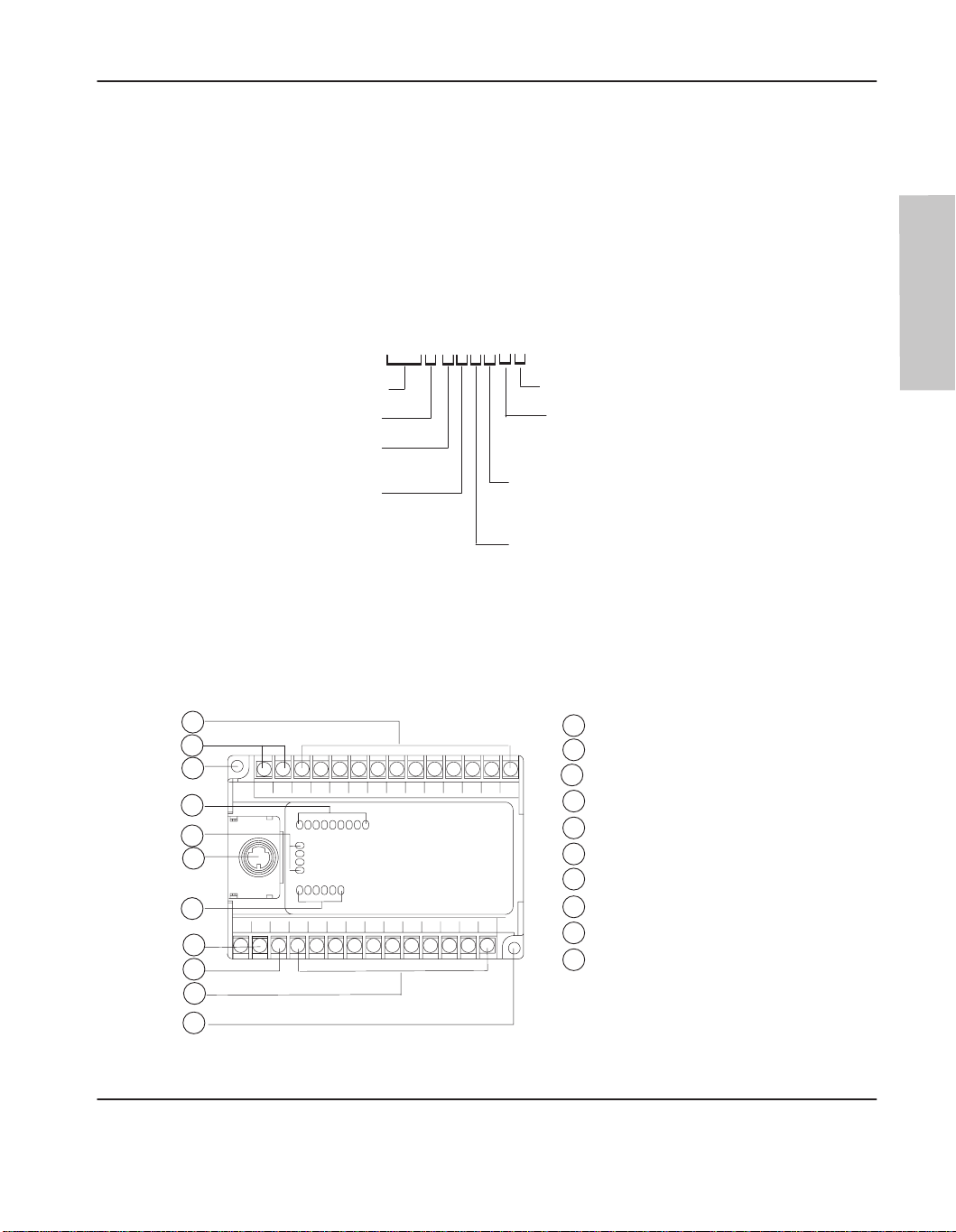
The hardware features of the controller are:
1
2
3
4
5
6
7
8
9
3
POWER
RUN
FAULT
FORCE
IN
OUT
1
Input terminals
2
dc output terminals (or not used)
3
Mounting hole
Input LEDs
4
Status LEDs
5
6
RS-232 communication channel
7
Output LEDs
8
Power supply line power
9
Ground screw
Output terminals
10
20142
1–3
Page 20

MicroLogix 1000 Programmable Controllers User Manual
Preface
Master Control Relay
A hard-wired master control relay (MCR) provides a reliable means for emergency
controller shutdown. Since the master control relay allows the placement of several
emer
gency-stop switches in dif
safety standpoint. Overtravel limit switches or mushroom head push buttons are
wired in series so that when any of them opens, the master control relay is
de-energized. This removes power to input and output device circuits. Refer to the
figure on page 1–6.
ferent locations, its installation is important from a
Note If
Never alter these cir
machine damage could result.
you ar
e using an external dc output power supply
rather than the ac line side of the supply to avoid the additional delay of power
supply turn-off.
The external ac line of the dc output power supply should be fused.
Connect a set of master contr
input and output circuits.
Place the main power disconnect switch where operators and maintenance personnel
have quick and easy access to it. If you mount a disconnect switch inside the
controller enclosure, place the switch operating handle on the outside of the
enclosure, so that you can disconnect power without opening the enclosure.
Whenever any of the emer
output devices should be removed.
When you use the master control relay to remove power from the external I/O
circuits, power continues to be provided to the controller’
diagnostic indicators on the processor can still be observed.
cuits to defeat their function, since serious injury and/or
, interrupt the dc output side
ol r
elays in series with the dc power supplying the
gency-stop switches are opened, power to input and
s power supply so that
The master control relay is not a substitute for a disconnect to the controller. It is
intended for any situation where the operator must quickly de-ener
only. When inspecting or installing terminal connections, replacing output fuses, or
working on equipment within the enclosure, use the disconnect to shut off power to
the rest of the system.
Note Do
with the safety of a dir
master contr
1–4
not contr
ol the master contr
ect connection between an emer
ol r
elay.
ol r
elay with the contr
gize I/O devices
oller. Pr
gency-stop switch and the
ovide the operator
Page 21

Using Emergency-Stop Switches
When using emergency-stop switches, adhere to the following points:
• Do not program emergency-stop switches in the controller program. Any
emergency-stop switch should turn off all machine power by turning off the
master control relay.
•
Observe all applicable local codes concerning the placement and labeling of
emer
gency-stop switches.
• Install emer
Make certain that relay contacts have a suf
Emer
gency-stop switches and the master control relay in your system.
gency-stop switches must be easy to reach.
• In the following illustration, input and output circuits are shown with MCR
protection. However
protection.
Installing Your Controller
ficient rating for your application.
, in most applications, only output circuits require MCR
Hardware
1–5
Page 22
MicroLogix 1000 Programmable Controllers User Manual
L1 L2
Preface
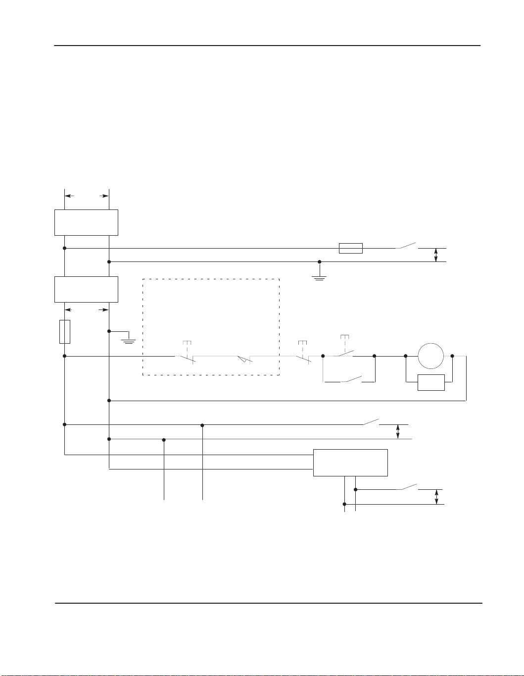
The following illustrations show the Master Control Relay wired in a grounded
system.
Note The
illustrations only show output cir
applications input cir
r
emove power fr
om all field devices, you must include MCR contacts in series with
input power wiring.
Schematic (Using IEC Symbols)
230V ac
Disconnect
Isolation
Transformer
230V ac
X1
Fuse
X2
Operation of either of these contacts will
remove power from the adapter external I/O
circuits, stopping machine motion.
Emergency-Stop
Push Button
cuits do not r
Overtravel
Limit Switch
cuits with MCR pr
equire MCR pr
Stop
otection. In most
otection; however
Fuse
Master Control Relay (MCR)
Start
Cat. No. 700-PK400A1
, if you need to
MCR
Suppressor
Cat. No. 700-N24
MCR
230V ac
I/O Circuits
1–6
(Lo) (Hi)
erminals: Connect to 230V ac
Line T
terminals of Power Supply
MCR
Suppr.
230V ac
I/O Circuits
24V dc
I/O Circuits
MCR
MCR
dc Power Supply
Use IEC 950/EN 60950
—
.
Line terminals: Connect to 24V dc
terminals of Power Supply
.
+
.
Page 23
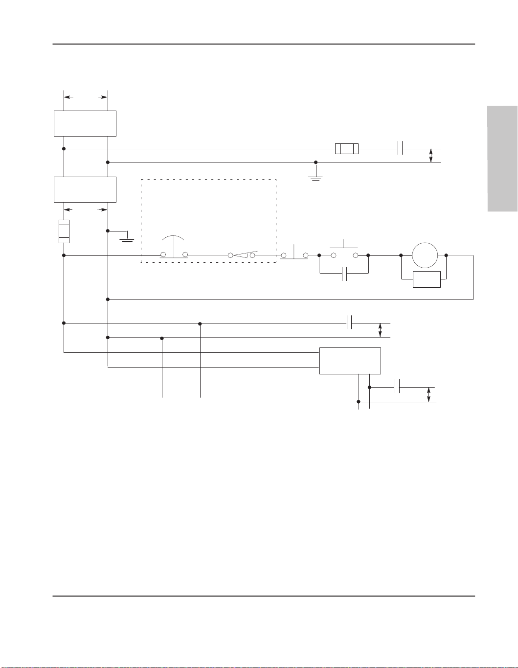
Schematic (Using ANSI/CSA Symbols)
L1 L2
230V ac
Disconnect
Fuse
Installing Your Controller
MCR
230V ac
Output
Circuits
Isolation
Transformer
115V ac
X1
Fuse
Operation of either of these contacts will
remove power from the adapter external I/O
X2
circuits, stopping machine motion.
(Lo) (Hi)
Line T
terminals of Power Supply
Emergency-Stop
Push Button
erminals: Connect to 1
.
Overtravel
Limit Switch
15V ac
Stop
Master Control Relay (MCR)
Cat. No. 700-PK400A1
.
+
Suppressor
Cat. No. 700-N24
1
15V ac
Output
Circuits
MCR
.
Start
MCR
MCR
dc Power Supply
Use N.E.C. Class 2
for UL Listing.
—
Line terminals: Connect to 24V dc
terminals of Power Supply
MCR
Suppr.
24V dc
Output
Circuits
Hardware
1–7
Page 24
MicroLogix 1000 Programmable Controllers User Manual
Preface
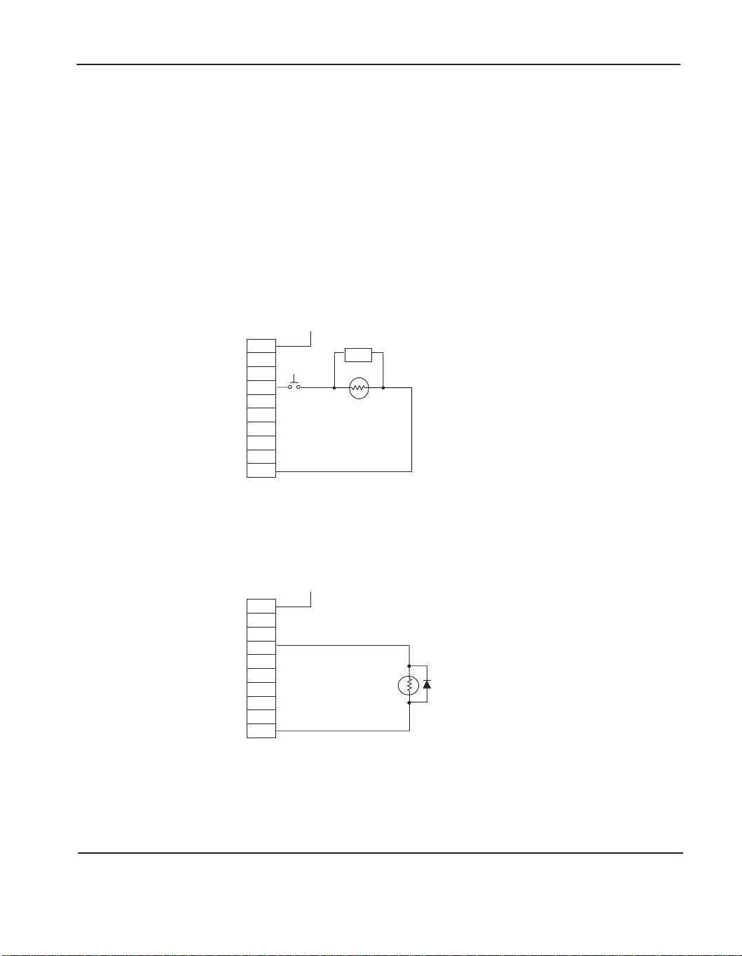
Using Surge Suppressors
Inductive
load devices such as motor starters and solenoids require the use of some
type of surge suppression to protect the controller output contacts. Switching
inductive loads without sur
ge suppression can
significantly reduce the lifetime of
relay contacts. By adding a suppression device directly across the coil of an
inductive device, you will prolong the life of the switch contacts. Y
ou will also
reduce the effects of voltage transients caused by interrupting the current to that
inductive device, and will prevent electrical noise from radiating into system wiring.
The following diagram shows an output with a suppression device. We recommend
that you locate the suppression device as close as possible to the load device.
+
dc or L1
ac
or dc
Outputs
VAC/VDC
OUT 0
OUT
OUT 2
OUT 3
OUT
OUT 5
OUT 6
OUT 7
COM
1
4
Snubber
dc COM or L2
If you connect a micro controller FET output to an inductive load, we recommend
that you use an 1N4004 diode for sur
ge suppression, as shown in the illustration that
follows.
1–8
Relay
or Solid State
dc Outputs
VAC/VDC
OUT 0
OUT
OUT 2
OUT 3
OUT
OUT 5
OUT 6
OUT 7
COM
+24V
dc
1
4
24V dc common
IN4004 Diode
Page 25
Installing Your Controller
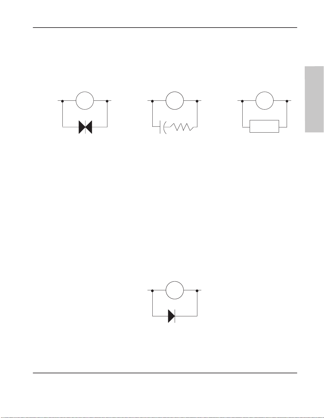
Suitable sur
an RC network, or an Allen-Bradley sur
components must be appropriately rated to suppress the switching transient
characteristic of the particular inductive device. See the table on page 1–10 for
recommended suppressors.
Output Device
Varistor
If you connect a micro controller triac output to control an inductive load, we
recommend that you use varistors to suppress noise. Choose a varistor that is
appropriate for the application. The suppressors we recommend for triac outputs
when switching 120V ac inductive loads are a Harris MOV
LA10A, or an Allen-Bradley MOV, catalog number 599-K04 or 599-KA04.
Consult the varistor manufacturer’s data sheet when selecting a varistor for your
application.
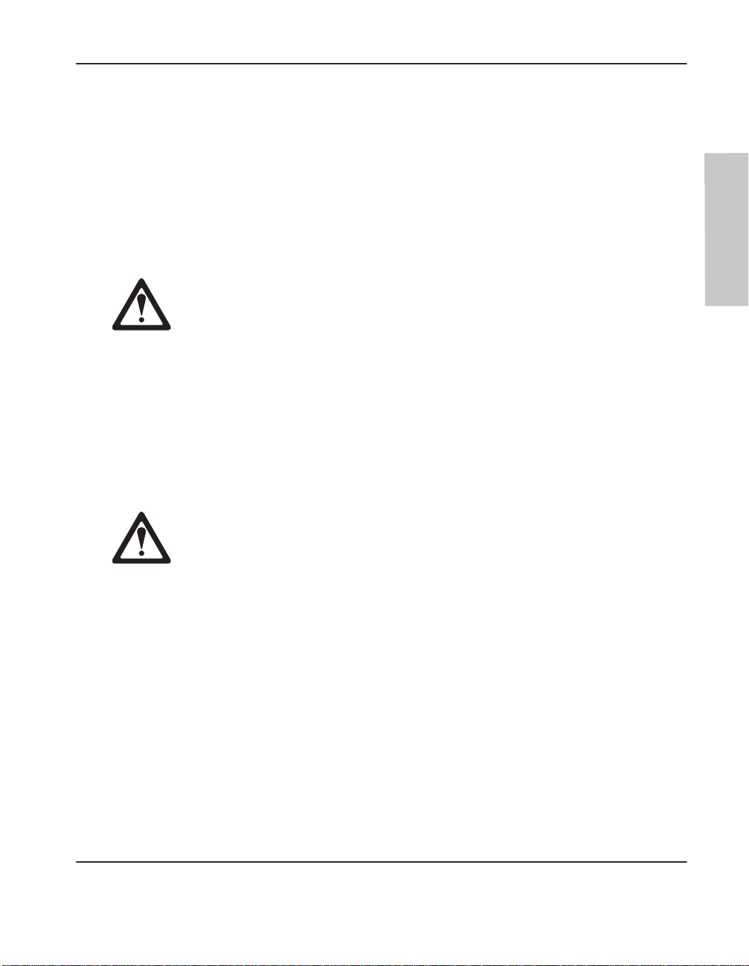
For inductive dc load devices, a diode is suitable. An 1N4004 diode is acceptable
for most applications. A sur
page 1–10 for recommended suppressors.
ge suppression methods for inductive ac load devices include a varistor
ge suppressor
Surge Suppression for Inductive ac Load Devices
Output DeviceOutput Device Output Device
RC Network
, all shown below. These
Surge
Suppressor
, part number V175
ge suppressor can also be used. See the table on
,
Hardware
As shown in the illustration below
, these sur
ge suppression circuits connect directly
across the load device. This reduces arcing of the output contacts. (High transient
can cause arcing that occurs when switching of
Surge Suppression for Inductive dc Load Devices
—
Output Device
Output Device
(A surge suppressor can also be used.)
Diode
f an inductive device.)
+
1–9
Page 26

MicroLogix 1000 Programmable Controllers User Manual
Preface
Recommended Surge Suppressors
We recommend the Allen-Bradley sur
ge suppressors shown in the following table
for use with Allen-Bradley relays, contactors, and starters.
Device Coil Voltage
Bulletin 509 Motor Starter
Bulletin 509 Motor Starter
Bulletin 100 Contactor
Bulletin 100 Contactor
Bulletin 709 Motor Starter 120V ac 1401-N10
Bulletin 700 Type R, RM Relays ac coil None Required
Bulletin 700 Type R Relay
Bulletin 700 Type RM Relay
Bulletin 700 Type R Relay
Bulletin 700 Type RM Relay
Bulletin 700 Type R Relay
Bulletin 700 Type RM Relay
Bulletin 700 Type R Relay
Bulletin 700 Type RM Relay
Bulletin 700 Type R Relay
Bulletin 700 Type RM Relay
Bulletin 700 Type N, P, or PK Relay 150V max, ac or DC 700-N24
120V ac
240V ac
120V ac
240V ac
12V dc
12V dc
24V dc
24V dc
48V dc
48V dc
115-125V dc
115-125V dc
230-250V dc
230-250V dc
Suppressor Catalog
599-K04
599-KA04
199-FSMA1
199-FSMA2
700-N22
700-N28
700-N10
700-N13
700-N16
700-N17
700-N11
700-N14
700-N12
700-N15
Number
1–10
Miscellaneous electromagnetic devices
limited to 35 sealed VA
150V max, ac or DC 700-N24
Page 27
Safety Considerations
Safety considerations are an important element of proper system installation.
Actively thinking about the safety of yourself and others, as well as the condition of
your equipment, is of primary importance. We recommend reviewing the following
safety considerations.
Disconnecting Main Power
Explosion Hazard — Do not replace components or disconnect equipment
unless power has been switched off and the area is known to be
non-hazardous.
The main power disconnect switch should be located where operators and
maintenance personnel have quick and easy access to it. In addition to
disconnecting electrical power, all other sources of power (pneumatic and hydraulic)
should be de-energized before working on a machine or process controlled by a
controller.
Installing Your Controller
Hardware
Safety Circuits
Explosion Hazard — Do not connect or disconnect connectors while circuit is
live unless ar
Circuits installed on the machine for safety reasons, like overtravel limit switches,
stop push buttons, and interlocks, should always be hard-wired directly to the master
control relay
opens, the master control relay is de-energized thereby removing power to the
machine. Never alter these circuits to defeat their function. Serious injury or
machine damage could result.
ea is known to be non-hazardous.
. These devices must be wired in series so that when any one device
1–11
Page 28

MicroLogix 1000 Programmable Controllers User Manual
Preface
Power Distribution
There are some points about power distribution that you should know:
• The master control relay must be able to inhibit all machine motion by
removing power to the machine I/O devices when the relay is de-energized.
• If you are using a dc power supply, interrupt the load side rather than the ac line
power. This avoids the additional delay of power supply turn-off. The dc
power supply should be powered directly from the fused secondary of the
transformer. Power to the dc input and output circuits is connected through a
set of master control relay contacts.
Periodic Tests of Master Control Relay Circuit
Any part can fail, including the switches in a master control relay circuit. The
failure of one of these switches would most likely cause an open circuit, which
would be a safe power-off failure. However
no longer provides any safety protection. These switches should be tested
periodically to assure they will stop machine motion when needed.
, if one of these switches shorts out, it
1–12
Page 29

Power Considerations
The following explains power considerations for the micro controllers.
Isolation Transformers
You may want to use an isolation transformer in the ac line to the controller. This
type of transformer provides isolation from your power distribution system and is
often used as a step down transformer to reduce line voltage. Any transformer used
with the controller must have a sufficient power rating for its load. The power
rating is expressed in volt-amperes (VA).
Power Supply Inrush
The MicroLogix power supply does not require or need a high inrush current.
However, if the power source can supply a high inrush current, the MicroLogix
power supply will accept it. There is a high level of inrush current when a large
capacitor on the input of the MicroLogix is charged up quickly.
If the power source cannot supply high inrush current, the only effect is that the
MicroLogix input capacitor char
determine whether the power source needs to supply a high inrush current:
• power
• power source sag if it cannot source inrush current
• the effect of the voltage sag on other equipment
-up sequence of devices in system
ges up more slowly
Installing Your Controller
. The following considerations
If the power source cannot provide high inrush current when the entire system in an
application is powered, the MicroLogix powers-up more slowly. If part of an
application’
powered, the source voltage may sag while the MicroLogix input capacitor is
charging. A power source voltage sag can affect other equipment connected to the
same power source. For example, a voltage sag may reset a computer connected to
the same power source.
s system is already powered and operating when the MicroLogix is
1–13
Page 30

MicroLogix 1000 Programmable Controllers User Manual
Preface
Loss of Power Source
The
power supply is designed to withstand brief power losses without af
operation of the system. The time the system is operational during power loss is
called “program scan hold-up time after loss of power.” The duration of the power
supply hold-up time depends on the type and state of the I/O, but is typically
between 20 milliseconds and 3 seconds. When the duration of power loss reaches
this limit, the power supply signals the processor that it can no longer provide
adequate dc power to the system. This is referred to as a power supply shutdown.
fecting the
Input States on Power Down
The power supply hold-up time as described above is generally longer than the
turn-on and turn-off times of the inputs. Because of this, the input state change from
“On” to “Off” that occurs when power is removed may be recorded by the processor
before the power supply shuts down the system. Understanding this concept is
important. The user program should be written to take this effect into account.
Other Types of Line Conditions
Occasionally the power source to the system can be temporarily interrupted. It is
also possible that the voltage level may drop substantially below the normal line
voltage range for a period of time. Both of these conditions are considered to be a
loss of power for the system.
Hardware
1–14
Page 31

Preventing Excessive Heat
For most applications, normal convective cooling keeps the controller within the
specified operating range. Ensure that the specified operating range is maintained.
Proper spacing of components within an enclosure is usually sufficient for heat
dissipation.
In some applications, a substantial amount of heat is produced by other equipment
inside or outside the enclosure. In this case, place blower fans inside the enclosure
to assist in air circulation and to reduce “hot spots” near the controller.
Additional cooling provisions might be necessary when high ambient temperatures
are encountered.
Installing Your Controller
Note Do
it fr
operation or damage to components. In extr
conditioning to pr
not bring in unfilter
om a corr
osive atmospher
otect against heat build-up within the enclosur
ed outside air
. Place the contr
e. Harmful contaminants or dirt could cause impr
eme cases, you may need to use air
oller in an enclosure to pr
e.
otect
oper
1–15
Page 32

MicroLogix 1000 Programmable Controllers User Manual
Preface
Controller Spacing
The following figure shows the recommended minimum spacing for the controller.
(Refer to appendix A for controller dimensions.)
Explosion Hazard — For Class I, Division 2 applications, this product must be
installed in an enclosure. All cables connected to the product must remain in
the enclosur
e or be pr
otected by conduit or other means.
Top
A
Bottom
Mounting the Controller
This
equipment is suitable for Class I, Division 2, Groups A, B, C, D or
non-hazardous locations only, when product or packaging is marked.
Explosion Hazard:
• Substitution of components may impair suitability for Class I, Division 2.
•
Be car
eful of metal chips when drilling mounting holes for your controller.
Drilled fragments that fall into the controller could cause damage. Do not
drill holes above a mounted controller if the protective wrap is removed.
The controller should be mounted horizontally within an enclosure, using a DIN rail
or mounting screws.
B
A. Greater than or equal to 50.8 mm (2 in.).
SideSide
A
B
B. Greater than or equal to 50.8 mm (2 in.).
20142
1–16
Page 33

Using a DIN Rail
c
Installing Your Controller
Use 35 mm (1.38 in.) DIN rails, such as item number 199-DR1 or 1492-DR5 from
Bulletin 1492.
To install your controller on the DIN rail:
1.Mount your DIN rail. (Make sure that the
placement of the controller on the DIN rail
meets the recommended spacing
requirements. Refer to controller
dimensions in appendix A.)
2.Hook the top slot over the DIN rail.
3.While pressing the controller against the
rail, snap the controller into position.
4.Leave the protective wrap attached until you
are finished wiring the controller.
B
A
C
To remove your controller from the DIN rail:
e a screwdriver in the DIN rail latch at
1.Pla
the bottom of the controller.
2.Holding the controller, pry downward on
the latch until the controller is released
from the DIN rail.
DIN
Rail
Side View
Side View
Protective Wrap
DIN
Rail
Call-out Dimension
A
84 mm (3.3 in.)
B
33 mm (1.3 in.)
C
16 mm (.63 in.)
Mounting
Template
20146
Hardware
DIN
Rail
20147
1–17
Page 34

MicroLogix 1000 Programmable Controllers User Manual
Preface
Using Mounting Screws
To install your controller using mounting screws:
Note Leave the protective wrap attached
until you are finished wiring the
controller.
1.Use the mounting template from
the MicroLogix 1000
Programmable Controllers
Installation Instructions,
publication 1761-5.1.2 or
MicroLogix 1000 (Analog)
Programmable Controllers
Installation Instructions,
publication 1761-5.1.3, that was
shipped with your controller.
2.Secure the template to the mounting
surface. (Make sure your controller
is spaced properly.)
3.Drill holes through the template.
4.Remove the mounting template.
5.Mount the controller.
Mounting Your Controller Vertically
Mounting
Template
Protective Wrap
(remove after wiring)
1–18
Your controller can also be mounted vertically within an enclosure using mounting
screws or a DIN rail. To insure the stability of your controller, we recommend using
mounting screws.
To insure the controller’s reliability, the following environmental specifications
must not be exceeded.
A
Top
A
Bottom
Greater than or equal
A.
to 50.8 mm (2 in.).
SideSide
A
A
Description: Specification:
Operating
Temperature
Operating Shock
(Panel mounted)
Operating Shock
(DIN rail mounted)
➀
DC input voltage derated linearly from +30°C (30V to 26.4V).
Discrete:
0°C to +45°C (+32
Analog: 0°C to +40°C (+32
9.0g peak acceleration (11±1 ms duration)
3 times each direction, each axis
7.0g peak acceleration (11±1 ms duration)
3 times each direction, each axis
°F to +113°F)
°F to +113°F)
➀
➀
Note: When mounting your controller vertically, the nameplate should be facing
downward.
Page 35

Wiring Your Controller
2
Wiring Your Controller
This chapter describes how to wire your controller. T
• grounding guidelines
•
sinking and sourcing circuits
• wiring recommendations
• wiring diagrams, input voltage ranges, and output voltage ranges
opics include:
Hardware
2–1
Page 36

MicroLogix 1000 Programmable Controllers User Manual
Preface
Grounding Guidelines
In solid-state control systems, grounding helps limit the effects of noise due to
electromagnetic interference (EMI). Use the heaviest wire gauge listed for wiring
your controller with a maximum length of 152.4 mm (6 in.). Run the ground
connection from the ground screw of the controller (third screw from left on output
terminal rung) to the ground bus.
Note
This symbol denotes a functional earth ground terminal which pr
impedance path between electrical cir
as noise immunity impr
All devices that connect to the user 24V power supply or to the RS-232 channel
must be refer
procedure may result in property damage or personal injury.
Chassis gr
connected. You must connect the chassis ground terminal scr
ground prior to connecting any devices.
On the 1761-L10BWB, 1761-L16BWB, 1761-L16BBB, 1761-L20BWB-5A,
1761-L32BBB, and 1761-L32BWB controllers, the user supply 24 V dc IN and
chassis gr
enced to chassis gr
ound, user 24V ground, and RS-232 ground are internally
ound are internally connected.
ovement.
cuits and earth for
ound or floating. Failure to follow this
non-safety
Protective
Wrap (remove after wiring)
ovides a low
purposes, such
ew to chassis
2–2
You must also provide an acceptable grounding path for each device in your
application. For more information on proper grounding guidelines, see the
Industrial Automation W
Remove the protective wrap before applying power to the controller. Failure
to remove the wrap may cause the controller to overheat.
iring and Gr
ounding Guidelines
publication 1770-4.1.
Page 37

Sinking and Sourcing Circuits
Any of the MicroLogix 1000 DC inputs can be configured as sinking or sourcing
depending on how the DC COM is wired on the MicroLogix.
Type Definition
The input energizes when high-level voltage is applied to the input terminal
Sinking Input
Sourcing Input
Sinking and Sourcing Wiring Examples
1761-L32BWA (Wiring diagrams also apply to 1761-L20BWA-5A,
-L16BWA, -L10BWA.)
(active high). Connect the power supply VDC (–) to the MicroLogix DC COM
terminal.
The input energizes when low-level voltage is applied to the input terminal
(active low). Connect the power supply VDC (+) to the MicroLogix DC COM
terminal.
Wiring Your Controller
Sinking Inputs
VDC (–)
for Sinking
DC
+
24V –
COM
DC OUT
Sourcing Inputs
VDC (+)
for Sourcing
DC
+
24V –
COM
DC OUT
Sourcing Inputs
14–30
VDC (+) for Sinking
I/0 I/1 I/2 I/3 I/4 I/5 I/6 I/7 I/8 I/11 I/12 I/13 I/14 I/15 I/16 I/17 I/18 I/19
VDC (+) for Sourcing
DC
COM
I/9 I/10
Sinking
VDC (–) for Sourcing
I/0 I/1 I/2 I/3 I/4 I/5 I/6 I/7 I/8 I/11 I/12 I/13 I/14 I/15 I/16 I/17 I/18 I/19
VDC (–) for Sinking
DC
COM
I/9 I/10
VDC
Inputs
14–30 VDC
VDC (–) for Sourcing
VDC (+)
for Sinking
2–3
Page 38

MicroLogix 1000 Programmable Controllers User Manual
Preface
1761-L32BWB, -L32BBB (Wiring Diagrams also apply to 1761-L20BWB-5A,
-L16BWB, -L10BWB, -L16BBB.)
Sinking
Inputs
Sourcing Inputs
14–30 VDC
VDC
(+) for Sinking
I/0 I/1 I/2 I/3 I/4 I/5 I/6 I/7 I/8 I/11 I/12 I/13 I/14 I/15 I/16 I/17 I/18
NOT
USED
VDC (–) for Sinking
NOT
DC
USED
COM
Sourcing Inputs
14–30 VDC
VDC (–) for Sourcing
DC
I/0 I/1 I/2 I/3 I/4 I/5 I/6 I/7 I/8 I/11 I/12 I/13 I/14 I/15 I/16 I/17 I/18
COM
NOT
USED
VDC (+) for Sourcing
NOT
USED
Wiring Recommendations
VDC (+) for Sourcing
DC
COM
VDC (–) for Sinking
DC
COM
14–30 VDC
I/9 I/10
Sinking Inputs
14–30 VDC
I/9 I/10
VDC (–) for Sourcing
I/19
VDC (+) for Sinking
I/19
2–4
Before you install and wire any device, disconnect power to the controller
system.
The following are general recommendations for wiring your controller system.
• Each wire terminal accepts 2 wires of the size listed below:
Wire Type Wire Size (2 wire maximum per terminal screw)
Solid #14 to #22 AWG
Stranded #16 to #22 AWG
Refer to page 2–24 for wiring your high-speed counter.
Page 39

Wiring Your Controller
Note The
output terminals of the micr
We recommend using either of the following AMP spade lugs: part number
53120-1, if using 22–16 AWG, or part number 53123-1, if using 16–14 AWG.
Note If
you use wir
pressur
wher
diameter of the terminal scr
es without lugs, make sur
ew heads is 5.5 mm (0.220 in.). The input and
o contr
oller ar
e designed for the following spade lugs:
Call-out Dimension
C
E
L
W
X
C+X
6.35 mm (0.250 in.)
10.95 mm (0.431 in.) maximum
14.63 mm (0.576 in.) maximum
6.35 mm (0.250 in.)
3.56 mm (0.140 in.)
9.91 mm (0.390 in.) maximum
e the wir
es ar
e secur
ely captur
ed by the
e plate. This is particularly important at the four end terminal positions
e the pr
essur
e plate does not touch the outside wall.
Hardware
20148i
Be car
eful when stripping wir
es. W
ire fragments that fall into the
controller could cause damage. Do not strip wires above a mounted
controller if the protective wrap is removed.
Protective
Wrap (remove after wiring)
2–5
Page 40

MicroLogix 1000 Programmable Controllers User Manual
Preface
Remove the protective wrap before applying power to the controller.
Failure to remove the wrap may cause the controller to overheat.
Calculate the maximum possible current in each power and common wire.
Observe all electrical codes dictating the maximum current allowable for
each wir
overheat, which can cause damage.
e size. Curr
ent above the maximum ratings may cause wiring to
United States Only: If the controller is installed within a potentially
hazardous environment, all wiring must comply with the requirements
stated in the National Electrical Code 501-4 (b).
• Allow for at least 50 mm (2 in.) between I/O wiring ducts or terminal strips and
the controller.
• Route incoming power to the controller by a path separate from the device
wiring. Where paths must cross, their intersection should be perpendicular.
Note Do
conduit. Wir
paths.
• Separate wiring by signal type. Bundle wiring with similar electrical
characteristics together.
• Separate input wiring from output wiring.
• Label wiring to all devices in the system. Use tape, shrink-tubing, or other
dependable means for labeling purposes. In addition to labeling, use colored
insulation to identify wiring based on signal characteristics. For example, you
may use blue for dc wiring and red for ac wiring.
not run signal or communications wiring and power wiring in the same
es with different signal characteristics should be r
outed by separate
Hardware
2–6
Page 41

Wiring Your Controller
Wiring Diagrams, Discrete Input and Output Voltage Ranges
The following pages show the wiring diagrams, discrete input voltage ranges, and
discrete output voltage ranges. Controllers with dc inputs can be wired as either
sinking or sourcing configurations. (Sinking and sourcing does not apply to ac
inputs.)
Note
This symbol denotes a functional earth ground terminal which pr
impedance path between electrical cir
as noise immunity impr
ovement.
cuits and earth for non-safety purposes, such
ovides a low
The 24V dc sensor power sour
circuits. It should only be used to power input devices (e.g. sensors,
switches). Refer to page 1–4 for information on MCR wiring in output
circuits.
1761-L16AWA Wiring Diagram
79–132V
ac
L2/N
85–264 VAC
L1
NOT
USED
L2/N
AC
COM
VAC
O/0
VDC
CR CR
VAC
V
COM
AC 1
1
NOT
USED
1761-L16AWA Input Voltage Range
0V ac 20V ac
ce should not be used to power output
L1
L2/N L1
AC
COM
VAC
VDC
V
AC 2
O/1
V
COM
AC 2
VAC
VDC
VDC 1
79–132V ac
VAC
O/2 O/3
VDC
VDC 2
VDC 1
VDC 2
COM
COM
I/9I/0 I/1 I/2 I/3 I/4 I/5 I/6 I/7 I/8
VAC
O/4
VDC
CR
VDC 3
79V ac
O/5
CR
VDC 3
COM
132V ac
Off
1761-L16AWA Output Voltage Range
0V ac 264V ac5V ac
0V dc 125V dc5V dc
?
?
Operating
Range
On
2–7
Page 42

MicroLogix 1000 Programmable Controllers User Manual
Preface
1761-L32AWA Wiring Diagram
79–132V
ac
L1 L2/N L1
I/0 I/1 I/2 I/3 I/4 I/5 I/6 I/7 I/8 I/11 I/12 I/13 I/14 I/15 I/16 I/17 I/18
AC
COM
NOT
USED
NOT
USED
AC
COM
L2/N
I/9 I/10
79–132V ac
I/19
85–264 VAC
L1 L2/N
VAC
1
V
COM
AC 1
VAC
VAC
O/0
VDC
VDC
CR CR CRCR CR
V
AC 2
O/1
V
COM
AC 2
VAC
VDC
VDC 1
O/2 O/3
VDC 1
COM
VAC
VDC
VDC 2
1761-L32AWA Input Voltage Range
0V ac 20V ac
Off
1761-L32AWA Output Voltage Range
0V ac 264V ac5V ac
0V dc 125V dc5V dc
O/4 O/5 O/6
?
VAC
O/8O/7 O/9 O/10 O/11
VDC
CR CRCR CR
VDC 3
VDC 2
COM
79V ac
CR
VDC 3
COM
132V ac
On
2–8
?
Operating
Range
Page 43

1761-L10BWA Wiring Diagram (Sinking Input Configuration)
Note: Refer to page 2–3 for additional configuration options.
14–30V dc
VDC
Com
VDC +
VDC
Com
VDC +
Wiring Your Controller
+
24V –
DC
I/0 I/1 I/2 I/3 I/4 I/5
COM
DC OUT
V
V
COM
AC 1
AC 1
85–264 VAC
L1
L2/N
VAC
O/0
VDC
CR CR CR
1761-L10BWA Input Voltage Range
0V dc 5V dc
0V dc 5V dc
Off
?
VAC
VDC
VAC
DC
COM
VAC
O/1
VDC
2
VDC 1
VDC 1
V
AC 2
COM
COM
NOT
USED
VAC
O/2 O/3
VDC
CR
VDC 2
VDC 2
COM
14V dc
14V dc
NOT
USED
NOT
USED
VDC 3
NOT
USED
NOT
USED
NOT
USED
NOT
USED
VDC 3
COM
26.4V dc @ 55° C (131° F)
30V dc @ 30° C (86° F)
HardwareHardware
On
1761-L10BWA Output Voltage Range
0V ac 264V ac5V ac
0V dc 125V dc5V dc
?
Operating
Range
2–9
Page 44

MicroLogix 1000 Programmable Controllers User Manual
Preface
1761-L16BWA Wiring Diagrams (Sinking Input Configuration)
Note: Refer to page 2–3 for additional configuration options.
14–30V dc
VDC +
I/9
+
24V –
DC OUT
VDC +
VDC
Com
DC
I/0 I/1 I/2 I/3 I/4 I/5 I/6 I/7 I/8
COM
DC
COM
VDC
Com
HardwareHardware
V
V
COM
AC 1
AC 1
85–264 VAC
L1
L2/N
VAC
VAC
O/0
VDC
VDC
CR CR CR
VAC
2
1761-L16BWA Input Voltage Range
0V dc 5V dc
0V dc 5V dc
Off
?
1761-L16BWA Output Voltage Range
0V ac 264V ac5V ac
0V dc 125V dc5V dc
O/1
V
COM
AC 2
VAC
VDC
VDC 1
VDC 1
COM
14V dc
14V dc
VAC
O/2 O/3
VDC
CR
VDC 2
VDC 2
COM
VAC
VDC
VDC 3
O/4
O/5
VDC 3
COM
26.4V dc @ 55° C (131° F)
30V dc @ 30° C (86° F)
On
2–10
?
Operating
Range
Page 45

1761-L32BWA Wiring Diagram (Sinking Input Configuration)
Note: Refer to page 2–3 for additional configuration options.
14-30 V dc
VDC
Com
VDC
+
VDC
Com
Wiring Your Controller
VDC +
+
24V –
DC OUT
85–264 VAC
L1 L2/N
VAC
1
DC
I/0 I/1 I/2 I/3 I/4 I/5 I/6 I/7 I/8 I/11 I/12 I/13 I/14 I/15 I/16 I/17 I/18 I/19
COM
VAC
O/0
VDC
CR CR CRCR CR
V
AC 1
COM
VAC
VDC
V
AC 2
O/1
V
COM
AC 2
DC
COM
VAC
VDC
VDC 1
O/2 O/3
VDC 1
COM
VAC
VDC
VDC 2
1761-L32BWA Input Voltage Range
0V dc 5V dc
0V dc 5V dc 14V dc
Off
?
1761-L32BWA Output Voltage Range
I/9 I/10
O/4 O/5 O/6
14V dc
VAC
O/8O/7 O/9 O/10 O/11
VDC
CR CRCR CR
VDC 3
VDC 2
COM
CR
VDC 3
COM
26.4V dc @ 55° C (131° F)
30V dc @ 30° C (86° F)
On
HardwareHardware
0V ac 264V ac5V ac
0V dc 125V dc5V dc
?
Operating
Range
2–11
Page 46

MicroLogix 1000 Programmable Controllers User Manual
Preface
1761-L10BWB Wiring Diagram (Sinking Input Configuration)
Note: Refer to page 2–4 for additional configuration options.
14–30 VDC
VDC
Com
VDC +
VDC
Com
14–30 VDC
VDC +
DC
+
NOT
USED
IN
24V –
DC
I/0 I/1 I/2 I/3 I/4 I/5
COM
VAC
O/0
VDC
CR
VDC 1
VDC 1
COM
NOT
USED
1761-L10BWB Input Voltage Range
0V dc 5V dc 14V dc
Off
?
1761-L10BWB Output Voltage Range
VAC
VDC
V
AC 1
O/1
V
COM
AC 1
VAC
VDC
DC
COM
VDC 2
NOT
USED
VAC
O/2 O/3
VDC
VDC 3
VDC 2
COM
CR
VDC 3
COM
NOT
USED
NOT
USED
NOT
NOT
USED
USED
NOT
NOT
USED
USED
26.4V dc @ 55° C (131° F)
On
Hardware
2–12
0V ac 264V ac5V ac
0V dc 125V dc5V dc
?
Operating
Range
Page 47

1761-L16BWB Wiring Diagram (Sinking Input Configuration)
Note: Refer to page 2–4 for additional configuration options.
VDC
Com
14–30V dc
VDC +
VDC
Com
14–30V dc
VDC +
Wiring Your Controller
DC
+
NOT
USED
IN
24V –
DC
I/0 I/1 I/2 I/3 I/4 I/5 I/6 I/7 I/8
COM
VAC
VAC
O/0
VDC
VDC
CR CR CR
V
AC 1
VDC 1
VDC 1
COM
NOT
USED
1761-L16BWB Input Voltage Range
0V dc 5V dc 14V dc
Off
?
1761-L16BWB Output Voltage Range
O/1
V
COM
AC 1
DC
COM
VAC
VDC
VDC 2
VDC 2
COM
VAC
O/2 O/3
VDC
CR
VDC 3
VDC 3
COM
VAC
VDC
VDC 4
O/4 O/5
VDC 4
COM
I/9
Hardware
26.4V dc @ 55° C (131° F)
On
0V ac 264V ac5V ac
0V dc 125V dc5V dc
?
Operating
Range
2–13
Page 48

MicroLogix 1000 Programmable Controllers User Manual
Preface
1761-L32BWB Wiring Diagram (Sinking Input Configuration)
Note: Refer to page 2–4 for additional configuration options.
NOT
USED
NOT
USED
Sinking Configuration
14–30V dc
VDC
Com
DC
I/0 I/1 I/2 I/3 I/4 I/5 I/6 I/7 I/8 I/11 I/12 I/13 I/14 I/15 I/16 I/17 I/18
COM
VDC +
DC
COM
VDC +
Sourcing Configuration
I/9 I/10
14–30V dc
VDC
Com
I/19
Hardware
DC IN
+
24V –
VDC 1
VDC 1
COM
VAC
VDC
VAC
O/0
VDC
CR CR CRCR CR
V
AC 1
O/1
V
COM
AC 1
VAC
VDC
VDC 2
O/2 O/3
VDC 2
COM
1761-L32BWB Input Voltage Range
0V dc 5V dc 14V dc
Off
?
1761-L32BWB Output Voltage Range
0V ac 264V ac5V ac
0V dc 125V dc5V dc
VAC
O/4 O/5 O/6
VDC
VDC 3
VAC
O/8O/7 O/9 O/10 O/11
VDC
CR CRCR CR
VDC 4
VDC 3
COM
On
CR
VDC 4
COM
26.4V dc @ 55° C (131° F)
2–14
?
Operating
Range
Page 49

1761-L32AAA Wiring Diagram
79–132V
ac
L1 L2/N L1
I/0 I/1 I/2 I/3 I/4 I/5 I/6 I/7 I/8 I/11 I/12 I/13 I/14 I/15 I/16 I/17 I/18
NOT
USED
NOT
USED
AC
COM
L2/N
AC
COM
I/9 I/10
Wiring Your Controller
79–132V ac
I/19
85–264 VAC
L1 L2/N
VAC
0
V
COM
AC 0
VAC
VDC
VAC
O/0
VDC
CR CR CRCR CR
V
AC 1
O/1
V
COM
AC 1
VAC
O/2 O/3
AC 2
V
1761-L32AAA Input Voltage Range
0V ac 20V ac
Off
1761-L32AAA Output Voltage Range
0V ac 264V ac85V ac
?
V
COM
?
AC 2
VAC
O/4 O/5 O/6
AC 3
V
VAC
O/8O/7 O/9 O/10 O/11
CR CRCR CR
V
AC 4
V
AC 3
COM
79V ac
Operating
Range
V
COM
On
CR
AC 4
132V ac
2–15
Page 50

MicroLogix 1000 Programmable Controllers User Manual
Preface
1761-L16BBB Wiring Diagrams (Sinking Input Configuration)
Note: Refer to page 2–4 for additional configuration options.
VDC
Com
14–30V dc
VDC +
VDC
Com
14–30V dc
VDC +
DC IN
+
24V –
VDC 1
COM
NOT
USED
DC
I/0 I/1 I/2 I/3 I/4 I/5 I/6 I/7 I/8
COM
VAC
VAC
O/0
VDC
VDC
CR
V
AC 1
V
COM
AC 1
V
AC 2
VDC 1
NOT
USED
1761-L16BBB Input Voltage Range
0V dc 5V dc 14V dc
Off
?
1761-L16BBB Output Voltage Range
O/1
V
COM
AC 2
DC
COM
DC
24V+
VDC 2
Sourcing Outputs
O/2 O/3 O/4 O/5
VDC 2
COM
DC
24V–
I/9
NOT
USED
26.4V dc @ 55° C (131° F)
On
Hardware
2–16
0V dc 26.4V dc20.4V dc
?
Operating
Range
Page 51

1761-L32BBB Wiring Diagram (Sinking Input Configuration)
ЙЙЙЙЙЙЙЙЙ
Note: Refer to page 2–4 for additional configuration options.
NOT
USED
DC IN
+
24V –
VDC 1
NOT
USED
Sinking Configuration
14–30V dc
VDC
Com
DC
I/0 I/1 I/2 I/3 I/4 I/5 I/6 I/7 I/8 I/11 I/12 I/13 I/14 I/15 I/16 I/17 I/18
COM
VAC
VDC
V
AC 1
VDC 1
COM
V
COM
AC 1
VDC +
VAC
O/0
VDC
CR
V
AC 2
V
COM
VDC +
DC
COM
DC
O/1
O/2 O/3 O/4 O/5 O/6
24V+
VDC 2
AC 2
VDC 2
COM
I/9 I/10
Sourcing Outputs
Sourcing Configuration
14–30V dc
O/8O/7 O/9 O/10 O/11
Wiring Your Controller
DC
NOT
24V–
USED
VDC
Com
I/19
1761-L32BBB Input Voltage Range
0V dc 5V dc
Off
?
1761-L32BBB Output Voltage Range
0V dc 26.4V dc20.4V dc
?
14V dc
26.4V dc @ 55° C (131° F)
On
Operating
Range
2–17
Page 52

MicroLogix 1000 Programmable Controllers User Manual
Preface
1761-L20AWA-5A Wiring Diagram
Note: Refer to pages 2–21 through 2–23 for additional information on analog
wiring.
79–132V
ac
L1 L2/N L1
VAC
VDC
V
AC 2
O/1
V
COM
AC 2
AC
COM
VAC
VDC
VDC 1
O/2 O/3
VDC 1
COM
I/0 I/1 I/2 I/3 I/4 I/5 I/6 I/7 I/8 I/11
VAC
O/0
VDC
CR CR CRCR CR
NOT
USED
85–264 VAC
L1 L2/N
L2/N
NOT
AC
USED
COM
VAC
1
V
AC 1
COM
1761-L20AWA-5A Input Voltage Range
0V ac 20V ac
Off
?
79–132V ac
VAC
VDC
VDC 2
I/9 I/10
O/4 O/5 O/6
O/7
CR
VDC 2
COM
79V ac
NOT
USED
IA
SHD
OA
SHD
IA/0
V (+)
OA/0
V (+)
IA/1
V (+)
Analog
Channel
Analog
Channels
OA/0
I (+)
IA
(–)
On
IA
I (+)
SHD
OA
(–)
(–)
I (+)
IA
IA/3
IA/2
132V ac
1761-L20AWA-5A Output Voltage Range
0V ac 264V ac5V ac
0V dc 125V dc5V dc
?
2–18
Operating
Range
Page 53

1761-L20BWA-5A Wiring Diagram (Sinking Input Configuration)
Note: Refer to page 2–3 for additional discrete configuration options.
Refer to pages 2–21 through 2–23 for additional information on analog
wiring.
Analog
Channels
VDC (–)
VDC (+)
VDC (–)
14–30V dc
VDC (+)
Wiring Your Controller
+
24V –
DC OUT
85–264 VAC
L1 L2/N
VAC
1
DC
I/0 I/1 I/2 I/3 I/4 I/5 I/6 I/7 I/8 I/11
COM
VAC
O/0
VDC
CR CR CRCR CR
V
AC 1
COM
VAC
VDC
DC
COM
VAC
O/1
VDC
V
AC 2
V
COM
AC 2
VDC 1
O/2 O/3
VDC 1
COM
VAC
VDC
VDC 2
I/9 I/10
O/4 O/5 O/6
O/7
CR
VDC 2
COM
1761-L20BWA-5A Discrete Input Voltage Range
0V dc 5V dc
0V dc 5V dc
Off
?
14V dc
14V dc
1761-L20BWA-5A Relay Output Voltage Range
0V ac 264V ac5V ac
0V dc 125V dc5V dc
NOT
USED
IA
OA
SHD
IA/0
V (+)
OA/0
V (+)
IA/1
V (+)
OA/0
I (+)
Analog
Channel
(–)
OA
(–)
IA
SHD
26.4V dc @ 55° C (131° F)
30V dc @ 30° C (86° F)
On
IA
SHD
I (+)
(–)
IA
IA/3
IA/2
I (+)
?
Operating
Range
2–19
Page 54

MicroLogix 1000 Programmable Controllers User Manual
Preface
1761-L20BWB-5A Wiring Diagram (Sinking Input Configuration)
Note: Refer to page 2–4 for additional discrete configuration options.
Refer to pages 2–21 through 2–23 for additional information on analog
wiring.
NOT
USED
NOT
USED
14–30V dc
(–)
I/0 I/1 I/2 I/3 I/4 I/5 I/6 I/7 I/8 I/11
DC
COM
VDC
VDC +
VDC (–)
DC
COM
14–30V dc
I/9 I/10
VDC (+)
IA
SHD
IA/0
V (+)
IA/1
V (+)
Analog
Channels
IA
(–)
IA
SHD
IA/2
I (+)
IA
IA/3
(–)
I (+)
DC IN
+
24V –
VDC 1
VDC 1
COM
VAC
VAC
O/0
VDC
VDC
CR CR CRCR CR
V
AC 1
O/1
V
COM
AC 1
VAC
VDC
VDC 2
O/2 O/3
VDC 2
COM
VAC
VDC
VDC 3
O/4 O/5 O/6
O/7
CR
VDC 3
COM
NOT
USED
1761-L20BWB-5A Discrete Input Voltage Range
0V dc 5V dc 14V dc
Off
?
1761-L20BWB-5A Relay Output Voltage Range
0V ac 264V ac5V ac
0V dc 125V dc5V dc
?
Operating
Range
OA
SHD
V (+)
Analog
Channel
(–)
I (+)
OA
OA/0
OA/0
26.4V dc @ 55° C (131° F)
On
2–20
Page 55

Wiring Your Controller
Minimizing Electrical Noise on Analog Controllers
Inputs on analog employ digital high frequency filters that significantly reduce the
ef
fects of electrical noise on input signals. However
applications and environments where analog controllers are installed and operating,
it is impossible to ensure that all environmental noise will be removed by the input
filters.
, because of the variety of
Several specific steps can be taken to help reduce the ef
on analog signals:
• install the MicroLogix 1000 system in a properly rated (i.e., NEMA) enclosure.
Make sure that the MicroLogix 1000 system is properly grounded.
• use Belden cable #8761 for wiring the analog channels making sure that the
drain wire and foil shield are properly earth grounded at one end of the cable.
• route the Belden cable separate from any other wiring. Additional noise
immunity can be obtained by routing the cables in grounded conduit.
A system may malfunction due to a change in the operating environment after a
period of time. We recommend periodically checking system operation, particularly
when new machinery or other noise sources are installed near the MicroLogix 1000
system.
Grounding Your Analog Cable
Use
shielded communication cable (Belden #8761). The Belden cable has two
signal wires (black and clear), one drain wire and a foil shield. The drain wire and
foil shield must be grounded at one end of the cable. Do not earth ground the drain
wire and foil shield at both
ends of the cable.
fects of environmental noise
Foil Shield
Insulation
Clear Wire
Black Wire
Drain Wire
2–21
Page 56

MicroLogix 1000 Programmable Controllers User Manual
Preface
Wiring Your Analog Channels
Analog input circuits can monitor current and voltage signals and convert
them to serial digital data. The analog output can support either a voltage or
a current function.
Sensor 3
(I) Current
Sensor 4
(I) Current
Sensor 1
(V) V
oltage
Sensor 2
(V) Voltage
Jumper
unused
inputs.
I/10 I/11
VAC
O/4 O/5 O/6
VDC
IA
SHD
IA/0
V (+)
IA/1
V (+)
O/7
IA
(–)
NOT
USED
You can configure either voltage
or current output operation.
IA
SHD
OA
SHD
IA/2
I (+)
OA/0
V (+)
– OR –
IA/3
I
(+)
OA/0
I (+)
IA
(–)
OA
(–)
meter
For increased noise immunity, connect a ground wire directly from the
shield terminals to chassis ground.
Important: The controller does not provide loop power for analog inputs.
2-Wire Transmitter
Use a power supply that matches the transmitter specifications.
Transmitter
+–
+Power
Supply
–
Transmitter
3-Wire Transmitter
+
Power
Supply
–
Supply Signal
GND
IA/0 – 3 (+)
IA (–)
Controller
IA/0 – 3 (+)
IA (–)
Controller
2–22
4-Wire Transmitter
+
Power
Supply
–
Transmitter
Supply Signal
+–+
–
Controller
IA/0 – 3 (+)
IA (–)
Page 57

Wiring Your Controller
Analog Voltage and Current Input and Output Ranges
Analog Voltage Input Range
–24V dc
Underrange
–10.5V dc 10.5V dc
Analog Current Input Range
–50 mA 50 mA
Underrange
Note The
without damage to the contr
withstand the application of 50 mA without damage.
–21 mA 21 mA
analog voltage inputs ar
Analog Voltage Output Range
0V dc 10V dc
Operating
Analog Current Output Range
Range
e pr
otected to
Overrange
Overrange
Operating
Range
Operating
Range
e pr
otected to withstand the application of 24V dc
oller
. The analog curr
ent inputs ar
24V dc
4 mA
Note The
curr
For information on analog signal and data word values using the nominal
transfer function formula, see page 5–5.
20 mA
Operating
Range
analog outputs ar
e pr
otected to withstand the short cir
ent outputs without damage to the contr
cuiting of the voltage or
oller.
2–23
Page 58

MicroLogix 1000 Programmable Controllers User Manual
Preface
Wiring Your Controller for High-Speed Counter Applications
To wire the controller for high-speed counter applications use input terminals I/0,
I/1, I/2, and I/3. Refer to chapter 12 for information on using the high-speed
counter.
Shielded cable is required for high-speed input signals 0–3 when the filter setting is
set to either 0.10 ms or 0.075 ms. We recommend Belden #9503 or equivalent for
lengths up to 305 m (1000 ft). Shields should be grounded only at the signal source
end of the cable. Ground the shield to the case of the signal source, so ener
coupled to the shield will not be delivered to signal source’
s electronics.
Hardware
gy
2–24
Page 59

Connecting the System
3
Connecting the System
This chapter describes how to wire your controller system. The method you use and
cabling required to connect your controller depends on what type of system you are
employing. This chapter also describes how the controller establishes
communication with the appropriate network.
For information on: See page:
DF1 protocol connections 3–2
DH-485 network connections 3–5
Establishing communication 3–17
Hardware
3–1
Page 60

MicroLogix 1000 Programmable Controllers User Manual
Preface
Connecting the DF1 Protocol
There are two ways to connect the MicroLogix 1000 programmable controller to
your personal computer using the DF1 protocol: using an isolated point-to-point
connection, or using a modem. Descriptions of these methods follow.
Chassis gr
ound, user 24V ground, and RS-232 ground are internally
connected. You must connect the chassis ground terminal scr
ground prior to connecting any devices. It is important that you understand
s gr
your personal computer’
ounding system before connecting to the
controller. An optical isolator is recommended between the controller and
your personal computer.
Making an Isolated Point-to-Point Connection
You can connect the MicroLogix 1000 programmable controller to your personal
computer using a serial cable from your personal computer’s serial port to the micro
controller.
Optical Isolator
(recommended)
Personal Computer
➀ We
recommend using an AIC+, catalog number 1761-NET
specific AIC+ cabling information.
➀
1761-CBL-PM02
Micro Controller
-AIC, as your optical isolator
ew to chassis
. See page 3–1
1 for
3–2
Page 61

1761-CBL-PM02 Series B Cable
Connecting the System
9
8
7
6
9-pin D-shell
Programming Device
9-Pin
9
8
7
6
5
4
3
2
1
5
4
3
2
1
8-pin Mini Din
678
Hardware
RI
CTS
RTS
DSR
GND
DTR
TXD
RXD
DCD
24V
GND
RTS
RXD
DCD
CTS
TXD
GND
Controller
8-Pin
1
2
3
4
5
6
7
8
3
5
4
12
20187
Using a Modem
You
can also use modems to connect a personal computer to one MicroLogix 1000
controller (using DF1 full-duplex protocol) or to multiple controllers (using DF1
half-duplex protocol), as shown in the illustration that follows. Do not attempt to
use DH-485 protocol through modems under any circumstance. (For information on
types of modems you can use with the micro controllers, see page D–9.)
3–3
Page 62

MicroLogix 1000 Programmable Controllers User Manual
Preface
Modem
Cable
Personal
Computer
DF1
full-duplex protocol (to 1 controller)
Modem
DF1 half-duplex master protocol (to multiple controllers)
Optical Isolator
(recommended)
➀
Micro Controller
Programming
Device
Modem Cable
Modem
➀ We
recommend using an AIC+, catalog number 1761-NET
Null Modem
specific AIC+ cabling information.
Constructing Your Own Null Modem Cable
If you construct your own null modem cable, the maximum cable length is 15.24 m
(50 ft) with a 25-pin or 9-pin connector. Refer to the following typical pinout:
Optical Isolator
9-Pin
TXD
3
RXD
2
GND
5
CD
1
DTR
4
DSR
6
CTS
8
7
RTS
Modem
Optical Isolator
Modem
1761-CBL-PM02
1761-CBL-PM02 Cable
➀
9-pin 8-pin Mini Din
-AIC, as your optical isolator
Modem
25-Pin
9-Pin
TXD
RXD
GND
CD
DTR
DSR
CTS
RTS
2
3
7
8
20
6
5
4
DF1 full-duplex protocol or
DF1 half-duplex slave protocol
Controller
. See page 3–1
3
2
5
1
4
6
8
7
1 for
3–4
Page 63

Connecting to a DH-485 Network
Connecting the System
Note Only
1000 analog contr
MicroLogix
discrete or MicroLogix 1000 analog)
1761-CBL-AM00
1761-CBL-
AIC+
(1761-NET-AIC)
MicroLogix
24V dc
(user supply needed if not connected
to a MicroLogix 1000 controller)
DH-485 Network
DB-9
mini-DIN 8 RS-232 port
DH-485 port
Series C or later Micr
ollers support DH-485 network connections.
1000 (Series C or later
connection
from
port 1 or port 2
to MicroLogix
or
HM02
1761-CBL-AP00
or
1761-CBL-PM02
RS-232 port
oLogix 1000 discr
AIC+
(1761-NET-AIC)
ete contr
APS
1761-CBL-AP00
1761-CBL-PM02
24V dc
(user supplied)
ollers and all Micr
PC
PC
to port 1
or port 2
or
1747-CP3
1761-CBL-AC00
or
oLogix
Hardware
Recommended Tools
To connect a DH-485 network, you need tools to strip the shielded cable and to
attach the cable and terminators to the AIC+ Advanced Interface Converter
recommend the following equipment (or equivalent):
Shielded Twisted Pair Cable #3106A or #9842 Belden
Stripping Tool 45-164 Ideal Industries
1/8 ” Slotted Screwdriver Not Applicable Not Applicable
Description Part Number Manufacturer
. W
e
3–5
Page 64

MicroLogix 1000 Programmable Controllers User Manual
Preface
DH-485 Communication Cable
The suggested DH-485 communication cable is either Belden #3106A or #9842.
The cable is jacketed and shielded with one or two twisted wire pairs and a drain
wire.
One pair provides a balanced signal line, and one additional wire is used for a
common reference line between all nodes on the network. The shield reduces the
effect of electrostatic noise from the industrial environment on network
communication.
The communication cable consists of a number of cable segments daisy-chained
together. The total length of the cable segments cannot exceed 1219 m (4000 ft).
When cutting cable segments, make them long enough to route them from one AIC+
to the next with sufficient slack to prevent strain on the connector. Allow enough
extra cable to prevent chafing and kinking in the cable.
Use these instructions for wiring the Belden #3106A or #9842 cable. (If you are
using standard Allen-Bradley cables, see the Cable Selection Guide on page 3–12.)
3–6
Page 65

Connecting the System
Connecting the Communication Cable to the DH-485 Connector
Note A
daisy-chained network is r
Single Cable Connection
Shrink Tubing
Recommended
Belden
#3106A or
#9842
Connector
Connector
Incorrect
Orange with White Stripes
White with Orange Stripes
Blue (#3106A) or
Blue with White Stripes (#9842)
ecommended. W
Belden
#3106A
or
#9842
Connector
Drain Wire
e do
not recommend the following:
Belden
#3106A or
#9842
6 Termination
5A
4B
Common
3
2 Shield
Chassis Ground
1
Hardware
Multiple Cable Connection
to Successive Device
to Previous Device
3–7
Page 66

MicroLogix 1000 Programmable Controllers User Manual
Preface
The
table below shows connections for Belden #3106A.
For
this W
ire/Pair
Shield/Drain Non-jacketed T
Blue Blue T
White/Orange
The
table below shows connections for Belden #9842.
For
this W
ire/Pair
Shield/Drain Non-jacketed T
Blue/White
White/Orange
➀
T
o prevent confusion when installing the communication cable, cut back the white with blue stripe wire
immediately after the the insulation jacket is removed. This wire is not used by DH-485.
Connect this W
White with Orange Stripe
Orange with White Stripe
Connect this W
White with Blue Stripe
Blue with White Stripe
White with Orange Stripe
Orange with White Stripe
ire To this Terminal
erminal 2 – Shield
erminal 3 – (Common)
T
erminal 4 – (Data B)
T
erminal 5 – (Data A)
ire To this Terminal
erminal 2 – Shield
Cut back – no connection
T
erminal 3 – (Common)
T
erminal 4 – (Data B)
T
erminal 5 – (Data A)
➀
Grounding and Terminating the DH-485 Network
Only one connector at the end of the link must have Terminals 1 and 2 jumpered
together. This provides an earth ground connection for the shield of the
communication cable.
Both ends of the network must have Terminals 5 and 6 jumpered together. This
connects the termination impedance (of 120Ω
required by the DH-485 specification.
End-of-Line Termination
3–8
Jumper
Belden
#3106A or #9842 Cable
1219 m (4000 ft) Maximum
Jumper
Jumper
) that is built into each AIC+ as
Page 67

Connecting the AIC+
Connecting the System
Note Only
1000 analog contr
You can connect an unpowered AIC+, catalog number 1761-NET-AIC, to the
network without disrupting network activity. In addition, if a MicroLogix 1000
controller powers an AIC+ that is connected to the network, network activity will
not be disrupted should the MicroLogix 1000 controller be removed from the AIC+.
The figure that follows shows the external wiring connections and specifications of
the AIC+.
Series C or later Micr
ollers support DH-485 connections with the AIC+.
AIC+ Advanced Interface Converter
oLogix 1000 discr
(1761-NET-AIC)
ete contr
ollers and all Micr
oLogix
Hardware
Item Description
Port
1 – DB-9 RS-232, DTE
Port 2 – mini-DIN 8 RS-232
Port 3 – DH-485 Phoenix plug
DC Power Source selector switch
(cable = port 2 power source, external = external power source connected to item 5)
T
erminals for external 24V dc power supply and chassis ground
For additional information on connecting the AIC+, see the Advanced Interface
Converter (AIC+) and DeviceNet Interface (DNI) Installation Instructions,
Publication 1761-5.11.
3–9
Page 68

MicroLogix 1000 Programmable Controllers User Manual
Preface
DF1 Isolated Point-to-Point Connection
AIC+
(1761-NET-AIC)
1761-CBL-AM00
1761-CBL-HM02
or
Selection Switch Up
24V
dc
(Not needed in this
configuration since the
MicroLogix 1000 provides
power to the AIC+ via port 2.)
DH-485 Network Connection
MicroLogix
1000 (Series C or later discrete and all analog)
connection
port 1 or port 2
1761-CBL-AM00
1761-CBL-
AIC+
(1761-NET-AIC)
HM02
24V dc
(user supply needed if not connected
to a MicroLogix 1000 controller)
MicroLogix
DH-485 Network
to MicroLogix
or
MicroLogix 1000
from
1761-CBL-AP00
or
1761-CBL-PM02
(1761-NET-AIC)
1747-CP3 or 1761-CBL-AC00
AIC+
24V dc
(user supplied)
PC
APS
1761-CBL-AP00
1761-CBL-PM02
PC
to port 1
or port 2
or
1761-CBL-AC00
PC
1747-CP3
or
3–10
DB-9
RS-232 port
mini-DIN 8 RS-232 port
DH-485 port
Page 69

DF1 Isolated Modem Connection
Connecting the System
Constructing
1761-CBL-AM00
1761-CBL-HM02
AIC+
(1761-NET-AIC)
24V
(Not needed in this configuration
since the MicroLogix 1000 provides
power to the AIC+ via port 2.)
For additional information on connections using the AIC+, see the Advanced
Interface Converter (AIC+) and DeviceNet Interface (DNI) Installation Instructions,
Publication 1761-5.11.
Y
our Own Modem Cable
If you construct your own modem cable, the maximum cable length is 15.24 m (50
ft) with a 25-pin or 9-pin connector. Refer to the following typical pinout:
AIC+
Optical Isolator
9-Pin
3
2
5
1
4
6
8
7
or
Selection Switch Up
dc
TXD
RXD
GND
CD
DTR
DSR
CTS
RTS
MicroLogix 1000
Modem
User supplied modem cable
Modem
25-Pin
TXD
RXD
GND
CD
DTR
DSR
CTS
RTS
2
3
7
8
20
6
5
4
9-Pin
3
2
5
1
4
6
8
7
3–11
Page 70

MicroLogix 1000 Programmable Controllers User Manual
77C
9f
76 C C00
761-C
09
9
09
9
76 C 00
c77
Preface
Cable Selection Guide
1761-CBL-AC00
1747-CP3
Cable Length Connections from
1747-CP3
1761-CBL-AC00
Cable Length Connections from
1761-CBL-AS03
BL-AS
1
1761-CBL-AS
1761-CBL-AM00
3m (9.8 ft)
➀
45 cm (17.7 in)
1761-CBL-AS03
3m (9.8 ft)
.5m (31.17 ft)
.5m (31.17 ft)
SLC 5/03 or SLC 5/04 processor
PC COM port
PanelV
iew 550 through NULL modem adapter
DTAM Plus / DT
Port 1 on another AIC+
SLC 500 Fixed,
SLC 5/01, SLC 5/02, and SLC 5/03 processors
PanelV
AM Micro
iew 550 RJ45 port
1761-CBL-HM02
, channel 0
1761-CBL-AS09
External
to AIC+
port 1
port 1
port 1
port 1
port 1
to AIC+
port 3
port 3
➁
Power Supply
Required
yes external
yes external
yes external
yes external
yes external
External
Power Supply
Required
yes external
yes external
➁
➀
Power Selection
Switch Setting
Power Selection
Switch Setting
➁
Hardware
➀
1761-CBL-AM00
1761-CBL-HM02
3–12
Cable Length Connections from
45 cm (17.7 in)
➁
2m (6.5 ft)
➀
MicroLogix 1000
to port 2 on another AIC+
External power supply required unless the AIC+ is powered by the device connected to port 2, then
the selection switch should be set to cable.
➁
Series B or higher cables are required for hardware handshaking.
to AIC+
port 2
port 2
External
Power Supply
Required
no cable
yes external
Power Selection
Switch Setting
Page 71

Connecting the System
76 C 00
c77
1761-CBL-AP00
Cable Length Connections from
1761-CBL-AP00
1761-CBL-PM02
45 cm (17.7 in)
➁
2m (6.5 ft)
SLC 5/03 or SLC 5/04 processors, channel 0
MicroLogix 1000
PanelV
iew 550 through NULL modem adapter
DTAM Plus / DT
AM Micro
PC COM port
user
supplied cable
Cable Length Connections from
straight 9–25 pin
––
➀
modem or other communication device
External power supply required unless the AIC+ is powered by the device connected to port 2, then
the selection switch should be set to cable.
➁
Series B or higher cables are required for hardware handshaking.
1761-CBL-PM02
➁
to AIC+
port 2
port 1
port 2
port 2
port 2
to AIC+
port 1
External
Power Supply
Required
yes external
➀
yes
yes external
yes external
yes external
External
Power Supply
Required
➀
yes
Power Selection
Switch Setting
➀
external
Power Selection
Switch Setting
➀
external
3–13
Page 72

MicroLogix 1000 Programmable Controllers User Manual
Preface
Recommended User-Supplied Components
These components can be purchased from your local electronics supplier.
Component Recommended Model
external power supply and chassis
ground
NULL modem adapter
straight 9–25 pin RS-232 cable
power supply rated for 20.4–28.8V dc
standard A
see table below for port information if making own cables
T
DH-485
Port 2
s DCD signal
➂
TS)
connector Port 3
➀
DB-9 RS-232 Port 1
Pin
received line signal detector (DCD) same state as port 1’
received data (RxD) received data (RxD)
transmitted data (TxD) transmitted data (TxD)
DTE ready (DTR)
signal common (GRD) signal common (GRD)
DCE ready (DSR)
request to send (R
clear to send (CTS) clear to send (CTS)
not applicable not applicable not applicable
DB-9 RS-232
➁
➁
TS)
➀
1761-CBL-AP00 or 1761-CBL-PM02
cable straight D connector
Port
1
(1761-CBL-PM02 cable)
DTE ready (DTR)
DCE ready (DSR)
request to send (R
➂
An 8-pin mini DIN connector is used for making connections to port 2. This connector is not
commercially available. If you are making a cable to connect to port 2, you must configure your
cable to connect to the Allen-Bradley cable shown above.
➁
On port 1, pin 4 is electronically jumpered to pin 6. Whenever the AIC+ is powered on, pin 4 will
match the state of pin 6.
➂
In the 1761-CBL-PM02 cable, pins 4 and 6 are jumpered together within the DB-9 connector.
Port 3
DH-485 Connector
chassis ground
cable shield
signal ground
DH-485 data B
DH-485 data A
termination
not applicable
not applicable
Hardware
3–14
Page 73

Powering the AIC+
If you use an external power supply, it must be 24V dc. Permanent damage
will result if miswired with the wr
Set the DC Power Source selector switch to EXTERNAL before connecting the
power supply to the AIC+.
ong power sour
Connecting the System
ce.
Bottom View
24VDC
DC
NEUT
CHS
GND
Always connect the CHS GND (chassis ground) terminal to the nearest earth
ground. This connection must be made whether or not an external 24V dc
supply is used.
In normal operation with the MicroLogix 1000 programmable controller connected
to port 2 of the AIC+, the controller powers the AIC+. Any AIC+ not connected to
a controller requires a 24V dc power supply. The AIC+ requires 104 mA at 24V dc.
If both the controller and external power are connected to the AIC+, the power
selection switch determines what device powers the AIC+.
3–15
Page 74

MicroLogix 1000 Programmable Controllers User Manual
Preface
Power Options
Below are two options for powering the AIC+:
• Use the 24V dc user power supply (200 mA maximum) built into the
MicroLogix controller. The AIC+ is powered through a hard-wired connection
using a communication cable (1761-CBL-HM02, or equivalent) connected to
port 2.
• Use an external DC power supply with the following specifications:
– operating voltage: 24V dc +20% / –15%
– output current: 200 mA maximum
– rated NEC
Make a hard-wired connection from the external supply to the screw terminals
on the bottom of the AIC+.
If you use an external power supply, it must be 24V dc. Permanent damage
will result if miswired with the wr
ong power sour
Hardware
ce.
Installing and Attaching the AIC+
1. Take
2. Carefully plug the terminal block into the DH-485 port on the AIC+ you are
3. Provide strain relief for the Belden cable after it is wired to the terminal block.
3–16
care when installing the AIC+ in an enclosure so that the cable connecting
the MicroLogix 1000 controller to the AIC+ does not interfere with the
enclosure door.
putting on the network. Allow enough cable slack to prevent stress on the plug.
This guards against breakage of the Belden cable wires.
Page 75

Establishing Communication
When you connect a MicroLogix 1000 controller to a network, it automatically
finds which protocol is active (DF1 or DH-485), and establishes communication
accordingly. Therefore, no special configuration is required to connect to either
network.
However, to shorten the connection time, you can specify which protocol the
controller should attempt to establish communication with first. This is done using
the Primary Protocol bit, S:0/10. The default setting for this bit is DF1 (0). If the
primary protocol bit is set to DF1, the MicroLogix 1000 controller will attempt to
connect using the configured DF1 protocol; either full-duplex or half-duplex slave.
To have the controller first attempt DH-485 communication, set this bit to 1.
For DH-485 networks that will only contain MicroLogix controllers, at least one
controller must have its primary protocol bit set to 1 so that the network can be
initialized.
Automatic Protocol Switching
The MicroLogix 1000 Series D or later discrete and all MicroLogix 1000 analog
controllers perform automatic protocol switching between DH-485 and the
configured DF1 protocol. (The controller cannot automatically switch between DF1
full-duplex and DF1 half-duplex slave.) This feature allows you to switch from
active communication on a DF1 half-duplex network to the DH-485 protocol to
make program changes.
Connecting the System
Simply disconnect the MicroLogix controller from the DF1 half-duplex network and
connect it to your personal computer. The controller recognizes the computer is
attempting to communicate using the DH-485 protocol and automatically switches
to it. When your program changes are complete, you can disconnect your computer,
reconnect the modem, and the controller automatically switches back to the
configured DF1 protocol. For example, if you are using the DH-485 protocol to
make program changes and you connect an HHP
communication on a DF1 full-duplex network.
The following baud rate limitations affect autoswitching:
, you can switch to active
• If the configured DH-485 baud rate is 19200, the configured DF1 baud rate
must be 4800 or greater.
• If the configured DH-485 baud rate is 9600, the configured DF1 baud rate must
be 2400 or greater.
3–17
Page 76

MicroLogix 1000 Programmable Controllers User Manual
76 C 00
c77
76 C 00
c77
Preface
DeviceNet Communications
You
can also connect a MicroLogix to a DeviceNet network using the DeviceNet
Interface (DNI), catalog number 1761-NET-DNI. For additional information on
connecting the DNI, see the Advanced Interface Converter (AIC+) and DeviceNet
Interface (DNI) Installation Instructions, Publication 1761-5.11. For information on
how to configure and commission a DNI, see the
Publication 1761-6.5.
DeviceNet Interface User Manual,
The figure that follows identifies the ports of the DNI.
Use
this write–on
area to mark the
DeviceNet node
Address.
Cable Selection Guide
Cable Length Connections from
1761-CBL-AM00
1761-CBL-HM02
DNI DeviceNet Interface
(1761-NET-DNI)
1761-CBL-AM00
45 cm (17.7 in)
➀
2m (6.5 ft)
NODE
DANGER
GND
V–
CAN_L
NET
CAN_H
V+
TX/RX
MOD
DeviceNet
(Port 1)
(Replacement
connector part no.
1761–RPL–
–
RS–232
(
Port 2)
SHIEL
D
MicroLogix 1000 (all series)
MicroLogix 1000 (all series)
Hardware
0000)
1761-CBL-HM02
to DNI
port 2
port 2
3–18
1761-CBL-AP00
Cable Length Connections from
1761-CBL-APM00
1761-CBL-PM02
➀
Series B cables or higher are required for hardware handshaking.
45 cm (17.7 in)
➀
2m (6.5 ft)
SLC 5/03 or SLC 5/04 processors, channel 0
PC COM port
1761-CBL-PM02
to DNI
port 2
port 2
Page 77

Programming Overview
4
Programming Overview
This chapter explains how to program the MicroLogix 1000 programmable
controller. Read this chapter for basic information about:
• principles of machine control
• understanding file or
•
understanding how processor files are stored and accessed
• applying ladder logic to your schematics
• a model for developing your program
ganization and addressing
Programming
4–1
Page 78

MicroLogix 1000 Programmable Controllers User Manual
Preface
Principles of Machine Control
The controller consists of a built-in power supply, central processing unit (CPU),
inputs, which you wire to input devices (such as pushbuttons, proximity sensors,
limit switches), and outputs, which you wire to output devices (such as motor
starters, solid-state relays, and indicator lights).
Programming
Device
User Input Devices
Memory
Inputs
MicroLogix 1000 Programmable Controller
(Programs and Data)
CPU
Processor
Power Supply
Outputs
User Output Devices
CR
4–2
Page 79

Programming Overview
With the logic program entered into the controller, placing the controller in the
Run mode initiates an operating cycle. The controller’
s operating cycle consists of a
series of operations performed sequentially and repeatedly, unless altered by your
program logic.
input
overhead
scan
service
comms
output
scan
input
scan – the time required for the controller to scan and read all input data;
typically accomplished within µseconds.
program scan – the time required for the processor to execute the instructions in the
program. The program scan time varies depending on the instructions used and
each instruction’
Note Subroutine
deviations in the way the operating cycle is sequenced.
output scan – the time required for the controller to scan and write all output data;
typically accomplished within µseconds.
program
scan
Operating Cycle
s status during the scan time.
and interrupt instructions within your logic pr
Programming
ogram may cause
service communications – the part of the operating cycle in which communication
takes place with other devices, such as an HHP or personal computer
housekeeping and overhead – time spent on memory management and updating
.
timers and internal registers.
You enter a logic program into the controller using a programming device. The
logic program is based on your electrical relay print diagrams. It contains
instructions that direct control of your application.
4–3
Page 80

MicroLogix 1000 Programmable Controllers User Manual
Preface
Understanding File Organization
The processor provides control through the use of a program you create, called a
processor file. This file contains other files that break your program down into
more manageable parts.
Processor File Overview
Most of the operations you perform with the programming device involve the
processor file and the two components created with it: program files and data files.
Processor
Program Files
(14
Maximum)
The programming device stores processor files on har
File
Data Files
(8 Maximum)
d disk (or floppy disk)
.
Monitoring and editing of processor files is done in the workspace of the computer.
After you select a file from disk and edit it, you then save the file hard to disk,
replacing the original disk version with the edited version. The hard disk is the
recommended location for a processor file.
PROGRAMMING DEVICE
Workspace
01
Hard Disk
01
02
03
04
Uniquely named
processor files
4–4
Processor files are created in the offline mode using the programming device.
These files are then restored (downloaded), to the processor for online operation.
Page 81

Program Files
Programming Overview
Program files contain controller information, the main ladder program, interrupt
subroutines, and any subroutine programs. These files are:
• System Program (file 0) – This file contains various system related
information and user-programmed information such as processor type, I/O
configuration, processor file name, and password.
• Reserved (file 1) – This file is reserved.
• Main Ladder Program (file 2) – This file contains user-programmed
instructions defining how the controller is to operate.
•
User Err
fault occurs.
or Fault Routine (file 3) – This file is executed when a recoverable
• High-Speed Counter Interrupt (file 4) – This file is executed when an HSC
interrupt occurs. It can also be used for a subroutine ladder program.
• Selectable Timed Interrupt (file 5) – This file is executed when an STI occurs.
It can also be used for a subroutine ladder program.
• Subroutine Ladder Program (files 6 – 15) – These are used according to
subroutine instructions residing in the main ladder program file or other
subroutine files.
Programming
Data Files
Data files contain the status information associated with external I/O and all other
instructions you use in your main and subroutine ladder program files. In addition,
these files store information concerning processor operation. Y
files to store “recipes” and look-up tables if needed.
These files are organized by the type of data they contain. The data file types are:
ou can also use the
• Output (file 0) – This file stores the state of the output terminals for the
controller.
• Input (file 1) – This file stores the status of the input terminals for the
controller.
• Status (file 2) – This file stores controller operation information. This file is
useful for troubleshooting controller and program operation.
• Bit (file 3) – This file is used for internal relay logic storage.
• Timer (file 4) – This file stores the timer accumulator and preset values and
status bits.
4–5
Page 82

MicroLogix 1000 Programmable Controllers User Manual
Preface
• Counter (file 5) – This file stores the counter accumulator and preset values
and the status bits.
• Control (file 6) – This file stores the length, pointer position, and status bits for
specific instructions such as shift registers and sequencers.
• Integer (file 7) – This file is used to store numeric values or bit information.
Understanding How Processor Files are Stored and Accessed
The MicroLogix 1000 programmable controller uses two devices for storing
processor files: RAM and EEPROM. The RAM provides easy access storage
(i.e., its data is lost on a power down), while the EEPROM provides long-term
storage (i.e., its data is not lost on a power down). The diagram below shows how
the memory is allocated in the micro controller’
s processor
.
EEPROM
Backup Data
Retentive Data
Program Files
The memory device that is used depends on the operation being performed. This
section describes how memory is stored and accessed during the following
operations:
RAM
CPU Workspace
Retentive Data
Program Files
CPU
• download
• normal operation
• power down
• power up
4–6
Page 83

Download
Programming Overview
When the processor file is downloaded to the micro controller, it is first stored in the
volatile RAM. It is then transferred to the non-volatile EEPROM, where it is stored
as both backup data and retentive data.
Note If
Normal Operation
EEPROM
Backup Data
Retentive Data
Program Files
RAM
CPU Workspace
Retentive Data
Program Files
CPU
Programming Device
you want to ensur
ar
e using, save the pr
During normal operation, both the micro controller and your programming device
can access the processor files stored in the RAM. Any changes to retentive data that
occur due to program execution or programming commands affect only the retentive
data in the RAM.
The program files are never modified during normal operation. However, both the
CPU and your programming device can read the program files stored in RAM.
e that the backup data is the same for every micro controller you
ogram to disk befor
e downloading it to a micr
o contr
oller.
Programming
EEPROM
Backup Data
Retentive Data
Program Files
RAM
CPU Workspace
Retentive Data
Program Files
CPU
Programming Device
4–7
Page 84

MicroLogix 1000 Programmable Controllers User Manual
Preface
Power Down
When a power down occurs, only the retentive data is transferred from the RAM to
the EEPROM. (The program files do not need to be saved to the EEPROM since
they cannot be modified during normal operation.) If for some reason power is lost
before all of the retentive data is saved to the EEPROM, the retentive data is lost.
This may occur due to an unexpected reset or a hardware problem.
Power Up
EEPROM
Backup Data
Retentive Data
Program Files
RAM
CPU Workspace
Retentive Data
Program Files
CPU
Programming Device
During power up, the micro controller transfers the program files from the
EEPROM to the RAM. The retentive data is also transferred to the RAM, provided
it was not lost on power down, and normal operation begins.
EEPROM
Backup Data
Retentive Data
Program Files
RAM
CPU Workspace
Retentive Data
Program Files
CPU
Programming Device
4–8
Page 85

Programming Overview
If retentive data was lost on power down, the backup data from the EEPROM is
transferred to the RAM and used as the retentive data. In addition, status file bit
S2:5/8 (retentive data lost) is set and a recoverable major error occurs when going to
run.
EEPROM
Backup Data
Retentive Data
Program Files
RAM
CPU Workspace
Retentive Data
Program Files
CPU
Programming Device
Programming
4–9
Page 86

MicroLogix 1000 Programmable Controllers User Manual
Preface
Addressing Data Files
For the purposes of addressing, each data file type is identified by a letter
(identifier) and a file number.
File
Type
Output
Input
Status
Bit
Timer
Counter
Control
Integer
The addresses are made up of alphanumeric characters separated by delimiters.
Delimiters include the colon, slash, and period.
Specifying Logical Addresses
The format of a logical address, xf:e, corresponds directly to the location in data
storage.
Where: Is the:
x
f
:
e
File type: O—output T—timer
File #: 0—output 4—timer
File delimiter: Colon or semicolon delimiter separates file and structure/word numbers.
Element number: 0 to: 0—output 39—timer
Identifier
O
I
S
B
T
C
R
N
I—input C—counter
S—status R—control
B—binary N—integer
1—input 5—counter
2—status 6—control
3—binary 7—integer
1—input 31—counter
32—status 15—control
31—binary 104—integer
File
Number
0
1
2
3
4
5
6
7
4–10
Page 87

Programming Overview
You
assign logical addresses to instructions from the highest level (element) to the
lowest level (bit). Addressing examples are shown in the table below
.
To specify the
address of a:
Word within an integer file
Word within a structure file
(e.g., a timer file)
Bit within an integer file
Bit within a bit file
Use these parameters:
➀
File Type
File Number
File Delimiter
Word Number
T4:7.
File Type
File Number
File Delimiter
Structure Number
Delimiter
Word
7N : 2 / 5
File Type
File Number
File Delimiter
Word Number
Bit Delimiter
Bit Number
File Type
File Number
Bit Delimiter
Bit Number
Bit files are bit stream continuous files, and therefore you can
address them in two ways: by word and bit, or by bit alone.
7N:2
ACC
Programming
B3 /31
Bit within a structure file
(e.g., a control file)
File Type
File Number
File Delimiter
Structure Number
Delimiter
Mnemonic
➀
Some
programming devices support short addressing. This allows you to eliminate the file number and file
delimiter from addresses. (For example: N7:2=N2, T4:12.ACC=T12.ACC, B3:2/12=B2/12
programming device’s user manual for information on addressing capabilities.
R6:7 /DN
)
Consult
your
4–11
Page 88

MicroLogix 1000 Programmable Controllers User Manual
Preface
You can also address at the bit level using mnemonics for timer, counter, or control
data types. The available mnemonics depend on the type of data. See chapters 6
through 13 for more information.
Specifying Indexed Addresses
The
indexed address symbol is the # character
before the file-type identifier in a logical address. Y
indexed address in your ladder program.
Enter the offset value in word 24 of the status file (S:24). All indexed instructions
use the same word S:24 to store the offset value. The processor starts operation at
the base address plus the of
logic before each indexed address operation.
When you specify indexed addresses, follow these guidelines:
•
Make sure the index value (positive or negative) does not cause the indexed
address to exceed the file type boundary.
•
When an instruction uses more than two indexed addresses, the processor uses
the same index value for each indexed address.
• Set the index word to the offset value you want immediately before enabling an
instruction that uses an indexed address.
. Place the # character immediately
ou can use more than one
fset. Y
ou can manipulate the offset value in your ladder
Instructions with a # sign in an address manipulate the offset value stored at
S:24. Make sure you monitor or load the offset value you want prior to using
an indexed addr
with possible damage to equipment and/or injury to personnel.
Example of Indexed Addressing
The
following Masked Move (MVM) example uses an indexed address in the
source and destination addresses. If the of
processor manipulates the data stored at the base address plus the of
4–12
ess. Otherwise unpr
MVM
MASKED MOVE
Source #N7:10
Mask 0033
Dest #N7:50
edictable machine operation could occur
fset value is 10 (stored in S:24), the
fset.
0
0
Page 89

In
this example, the processor uses the following addresses:
Value: Base Address: Offset Value in S:24 Offset Address:
Source N7:10 10 N7:20
Destination N7:50 10 N7:60
Addressing File Instructions – Using the File Indicator (#)
The
file instructions below manipulate data table files. These files are addressed
with the # sign. They store an offset value in word S:24 (index register), just as with
indexed addressing discussed in the last section.
(LIFO Load)
Copy File
COP
Fill File
FLL
Bit Shift Left
BSL
Bit Shift Right
BSR
(FIFO Load)
FFL
(FIFO Unload)
FFU
If you are using file instructions and also indexed addr
you monitor and/or load the correct offset value prior to using an indexed
addr
ess. Otherwise, unpr
edictable operation could occur
personal injury and/or damage to equipment.
LFL
(LIFO Unload)
LFU
Sequencer Output
SQO
Sequencer Compare
SQC
Sequencer Load
SQL
Programming Overview
essing, make sur
, r
esulting in possible
Programming
e that
Numeric Constants
You can enter numeric constants directly into many of the instructions you program.
The range of values for most instructions is –32,768 through +32,767. These values
can be displayed or entered in several radixes. The radixes that can be displayed
are:
• Integer
• Binary
• ASCII
• Hexadecimal
4–13
Page 90

MicroLogix 1000 Programmable Controllers User Manual
Preface
When
entering values into an instruction or data table element, you can specify the
radix of your entry using the “&” special operator
enter data into an instruction or data table element are:
. The radixes that can be used to
• Integer (&N)
• Binary (&B)
• ASCII (&A)
• Hexadecimal (&H)
• BCD (&D)
• Octal (&O)
Numeric constants are used in place of data file elements. They cannot be
manipulated by the user program. You must enter the offline program editor to
change the value of a constant.
Applying Ladder Logics to Your Schematics
The logic you enter into the micro controller makes up a ladder program. A ladder
program consists of a set of instructions used to control a machine or a process.
4–14
Ladder logic is a graphical programming language based on electrical relay
diagrams. Instead of having electrical rung continuity, ladder logic is looking for
logical rung continuity. A ladder diagram identifies each of the elements in an
electromechanical circuit and represents them graphically
how your control circuit operates before you actually start the physical operation of
your system.
I
] [
input instructions output instruction
In a ladder diagram each of the input devices are represented in series or parallel
combinations across the rung of the ladder. The last element on the rung is the
output that receives the action as a result of the conditional state of the inputs on the
rung.
Each output instruction is executed by the controller when the rung is scanned and
the conditions on the rung are true. When the rung is not scanned or the logic
conditions on the rung do not create a true logic path, the output is not executed.
I
]/[
0
1
. This allows you to see
O
( )
1
Page 91

Programming Overview
The programming device allows you to enter a ladder logic program into the micro
controller.
In the following illustration, the electromechanical circuit shows PB1 and PB2, two
pushbuttons, wired in series with an alarm horn. PB1 is a normally open
pushbutton, and PB2 is normally closed. This same circuit is shown in ladder logic
by two contacts wired in series with an output. Contact I/0 and I/1 are
examine-if-closed instructions.➀ (For more information on this instruction, refer to
page 6–4.)
Electromechanical Circuit
PB1 PB2
➀
Contact
I1 would be an examine-if-open instruction ( ]/[ ) if PB2 was a normally open electromechanical circuit.
The
table below shows how these circuits operate. The table shows all possible
Alarm
Horn
Ladder Logic Program
I
] [] [
0
conditions for the electromechanical circuit, the equivalent state of the ladder logic
instructions, and the resulting output state.
If PB1 is: I/0 state is: And PB2 is: I/1 state is: Then the Alarm Horn (O/1) is:
not pushed 0 not pushed 1 silent
not pushed 0 pushed 0 silent
pushed 1 not pushed 1 alarm
pushed 1 pushed 0 silent
Developing Your Logic Program – A Model
I
1
O
( )
1
Programming
The following diagram can help you develop your application program. Each
process block represents one phase of program development. Use the checklist at
the right of the process block to help you identify the tasks involved with each
process.
4–15
Page 92

MicroLogix 1000 Programmable Controllers User Manual
Preface
Program
Development
Process
Design
Functional Specification
Detailed Analysis
Determine if Special
Features are Needed
Perform
Programming
Create Logic
Program
Confirm I/O
Addresses
Enter/Edit
Program
Program Development
Checklist
❏
Prepare a general description of how you want your
automated process to operate.
❏
Identify the hardware requirements.
❏
Match inputs and outputs with actions of the process.
❏
Add these actions to the functional specifications.
Do you need:
❏
Special interrupt routines?
❏
High-speed counting features?
❏
Sequencing Operations?
❏
FIFO or LIFO stack operations?
❏
Use worksheets if necessary to create program.
❏
Make sure I/O addresses match correct input and
output devices.
❏
Enter program using the programming device.
4–16
Check for
Completeness
Monitor/Troubleshoot
Program
Accept
Program
Run program.
❏
Review your functional specification and detailed
analysis for missing or incomplete information.
❏
Monitor and, if necessary
program that you entered.
❏
Resulting programs should match functional
specifications.
, troubleshoot the
Page 93

Using Analog
5
Using Analog
This chapter describes the operation of the MicroLogix 1000 analog controllers.
T
opics include:
• I/O Image
• I/O Configuration
• Input Filter and Update Times
• Converting Analog Data
5–1
Programming
Page 94

MicroLogix 1000 Programmable Controllers User Manual
Preface
I/O Image
The input and output image files of the MicroLogix 1000 analog controllers have
the following format:
Address Input Image Output Image Address
I:0.0 Discrete Input Word 0 Discrete Output Word 0 O:0.0
I:0.1 Discrete Input Word 1 Reserved O:0.1
I:0.2 Reserved Reserved O:0.2
I:0.3 Reserved Reserved O:0.3
I:0.4 Analog Input 0 (Voltage)
I:0.5 Analog Input 1 (Voltage)
I:0.6 Analog Input 2 (Current)
I:0.7 Analog Input 3 (Current)
Input
words 0 and 1 contain discrete input data. Unused inputs in the discrete inputs
Analog Output 0 (Voltage or
Current)
O:0.4
image space are reset during each input scan. Input words 2 and 3 are reserved and
are not updated by the controller. These inputs have no direct effect on controller
operation, but they can be modified like other data bits.
Input words 4–7 contain the status of the four analog input channels respectively.
Analog input image words are cleared at Going To Run (GTR). For enabled
channels, the analog input image is updated on a cyclical basis.
Output word 0 contains discrete output data. Output words 1–3 are reserved output
image space. Unused outputs in both the discrete output image space and the
reserved output image space have no direct effect on controller operation. But these
outputs can be modified like other data bits. Output word 4 holds the value of the
analog output channel.
5–2
Page 95

I/O Configuration
The analog input channels are single-ended (unipolar) circuits and can be
individually enabled or disabled. The default is all input channels enabled. The two
voltage inputs accept
The analog output channel is also a single-ended circuit. You can configure either
voltage (0V dc to +10V dc) or current (+4 to +20 mA) output operation. The
default is voltage output.
Using Analog
"10.5V dc, and the two current inputs accept "21 mA.
The output must be configured for either voltage or current, not both
determined by the output configuration. When in the Run mode and the output is
configured for voltage, the voltage output terminal is active and the current output
terminal is inactive. Similarly, when in the Run mode and the output is configured
for current, the current output terminal is active and the voltage output terminal is
inactive. When the system is not in Run mode, both the voltage and current outputs
are inactive.
Input Filter and Update Times
The MicroLogix analog input filter is programmable. The slower the filter setting,
the more immune the analog inputs are to electrical noise. The more immune the
analog inputs are to electrical noise, the slower the inputs will be to update.
Similarly, the faster the filter setting, the less immune the analog inputs are to
electrical noise. The less immune the analog inputs are to electrical noise, the faster
the inputs will be to update.
Programmable Filter Characteristics
1st Notch Freq
(Hz)
10 2.62 100.00 400.00 16
50 13.10 20.00 80.00 16
➀
60
250 65.50 4.00 16.00 15
➀
60
Hz is the default setting.
Filter
Bandwidth
(-3 dB Freq Hz)
15.72 16.67 66.67 16
Update Time
(mSec)
Settling Time
(mSec)
. This is
Resolution
(Bits)
5–3
Page 96

MicroLogix 1000 Programmable Controllers User Manual
Preface
The total update time for each channel is a combination of the Update Time and the
Settling Time. When more than one analog input channel is enabled, the maximum
update for each channel is equal to one ladder scan time plus the channel’
Time plus Settling T
ime. When only one analog input channel is enabled, the
maximum update for the channel is equal to the Update T
time.
Update Examples
Example 1 – All (4) channels enabled with 60 Hz filter selected (default settings).
Maximum Update Time = (4) x ladder scan time
(Each channel will be updated approximately three times per second.)
Example 2 – 1 channel enabled with 250 Hz filter selected.
s Update
ime plus one ladder scan
+ (4) x 16.67 ms
+ (4) x 66.67 ms
= 333.36 ms + (4) x ladder scan times
Maximum Update Time = ladder scan time + 4 ms
Input Channel Filtering
The analog input channels incorporate on-board signal conditioning. The purpose
of this conditioning is to reject the AC power line noise that can couple into an
analog input signal while passing the normal variations of the input signal.
Frequency components of the input signal at the filter frequency are rejected.
Frequency components below the filter bandwidth (–3 dB frequency) are passed
with under 3 dB of attenuation. This pass band allows the normal variation of
sensor inputs such as temperature, pressure and flow transducers to be input data to
the processor
Noise signals coupled in at frequencies above the pass band are sharply rejected.
An area of particular concern is the 50/60 Hz region, where pick-up from power
lines can occur
5–4
.
.
Page 97

Converting Analog Data
The analog input circuits are able to monitor current and voltage signals and convert
them to digital data. There are six terminals assigned to the input channels that
provide two voltage inputs, two current inputs and two return signals (commons).
Using Analog
The analog outputs can support either a current
or
voltage function. There are three
terminals assigned to the output channels that provide one voltage output, one
current output and a common (shared) terminal.
The following table shows sample Analog Signal and Data W
ord values using the
nominal transfer function formula:
N=Iin x 32767/21 where Iin (analog signal) is in milliamperes (mA)
x 32767/10.5 where Vin (analog signal) is in volts (V)
N=V
in
N=(I
– 4 mA) x 32767/16 mA where I
out
(analog signal) is in
out
milliamperes (mA)
N=V
Analog Signal Data Word
0V 0 0
5V 15603 16384
10V 31207 32767
4
mA
1
1 mA
20 mA
x 32767/10V where V
out
6241 0
17164 14336
31207 32767
Input Output
(analog signal) is in volts (V)
out
Converting Analog Input Data
Analog inputs convert current and voltage signals into 16-bit two’
binary values. To determine an approximate voltage that an input value represents,
use one of the equations shown on the following page.
s complement
5–5
Page 98

MicroLogix 1000 Programmable Controllers User Manual
2
767
Preface
10.5V
32,767
➀
The Input Value is the decimal value of the word in the
input image for the corresponding analog input.
For example, if an input value of 16,021 is in the input image,
the calculated value is:
10.5V
32,767
It should be noted that the actual value may vary within the
accuracy limitations of the module.
16,201 = 5.1915(V)
input value➀ = input voltage(V)
To determine an approximate current that an input value represents, you can use the
following equation:
1 mA
32,767
➁
The Input Value is the decimal value of the word in the
input image for the corresponding analog input.
For example, if an input value of 4096 is in the input image,
the calculated value is:
21 mA
4096 = 2.625 (mA)
32,767
It should be noted that the actual value may vary within
the accuracy limitations of the module.
input value➁ = input current (mA)
Converting Analog Output Data
Use the following equation to determine the decimal value for the current output:
5–6
32,767
16 mA
For example, if an output value of 8 mA is desired, the value to be put in the
corresponding word in the output image can be calculated as follows:
32,767
16 mA
Use the following equation to determine the decimal value for the voltage output:
32,
10V dc
For example, if an output value of 1V dc is desired, the value to be put in the
corresponding word in the output image can be calculated as follows:
32,767
10V dc
[Desired Current Output (mA) – 4 mA] = Output Decimal Value
(8 mA – 4 mA) = 8192
Desired Voltage Output (V dc) = Output Decimal Value
1V dc = 3277
Page 99

Using Basic Instructions
Purpose
Page
6
Bit Instructions
Using Basic Instructions
This chapter contains general information about the basic instructions and explains
how they function in your application program. Each of the basic instructions
includes information on:
• what the instruction symbol looks like
• typical execution time for the instruction
• how to use the instruction
In addition, the last section contains an application example for a paper drilling
machine that shows the basic instructions in use.
Instruction
Mnemonic Name
XIC
XIO Examine if Open Examines a bit for an Off condition. 6–4
Examine if Closed Examines a bit for an On condition. 6–4
Programming
OTE Output Energize Turns a bit On or Off. 6–5
OTL and
OTU
OSR One-Shot Rising Triggers a one time event. 6–7
Output Latch and
Output Unlatch
OTL turns a bit on when the rung is executed, and
this bit retains its state when the rung is not
executed or a power cycle occurs. OTU turns a bit
off when the rung is executed, and this bit retains its
state when the rung is not executed or when power
cycle occurs.
6–5
6–1
Page 100

MicroLogix 1000 Programmable Controllers User Manual
Purpose
Page
Preface
Timer/Counter Instructions
Instruction
Mnemonic Name
TON Timer On-Delay Counts timebase intervals when the instruction is
TOF Timer Off-Delay Counts timebase intervals when the instruction is
RTO Retentive Timer Counts timebase intervals when the instruction is
CTU Count Up Increments the accumulated value at each false-to-
CTD Count Down Decrements the accumulate value at each false-to-
RES Reset Resets the accumulated value and status bits of a
About the Basic Instructions
These instructions, when used in ladder programs represent hardwired logic circuits
used for the control of a machine or equipment.
true.
6–11
6–12
false.
6–14
true and retains the accumulated value when the
instruction goes false or when power cycle occurs.
6–18
true transition and retains the accumulated value
when the instruction goes false or when power cycle
occurs.
6–19
true transition and retains the accumulated value
when the instruction goes false or when power cycle
occurs.
6–20
timer or counter. Do not use with TOF timers.
The basic instructions are separated into three groups: bit, timer, and counter.
Before you learn about the instructions in each of these groups, we suggest that you
read the overview that precedes the group:
• Bit Instructions Overview
• Timer Instructions Overview
• Counter Instructions Overview
6–2
 Loading...